Technical Manual - Section 3 (Safety Hazards)
Technical Manual - Section 3 (Safety Hazards)
Technical Manual - Section 3 (Safety Hazards)

Create successful ePaper yourself
Turn your PDF publications into a flip-book with our unique Google optimized e-Paper software.
OR-OSHA TECHNICAL MANUAL OR-OSHA TECHNICAL MANUAL OR-OSHA TECHNICAL MANUAL<br />
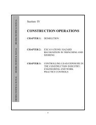
<strong>Section</strong> III<br />
SAFETY HAZARDS<br />
CHAPTER 1:<br />
CHAPTER 2:<br />
CHAPTER 3:<br />
CHAPTER 4:<br />
OILWELL DERRICK<br />
STABILITY: GUYWIRE<br />
ANCHOR SYSTEMS<br />
PETROLEUM REFINING<br />
PROCESSES<br />
PRESSURE VESSEL<br />
GUIDELINES<br />
INDUSTRIAL ROBOTS AND<br />
ROBOT SYSTEM SAFETY<br />
III
III
SECTION III: CHAPTER 1<br />
OIL WELL DERRICK STABILITY: GUYWIRE<br />
ANCHOR SYSTEMS<br />
A. INTRODUCTION<br />
Work-over Rigs are mast type devices that vary significantly<br />
from crane or other boom (mast) type equipment. Work-over<br />
Rigs experience constant and varying dynamic loading<br />
conditions. They are subjected to various compression<br />
forces, along with jarring and wind loading. Other forces<br />
induced by pipe, tubing, etc. being stacked in the derrick and<br />
workers aloft on the derrick platform, as well as an<br />
ever-changing number of lateral and vertical forces are also<br />
present. Because of a work-over rig's dynamic environment,<br />
the health and safety of the operation is dependent upon the<br />
stability of the rig and its guy anchor system.<br />
according to the type of soil and its holding capacity, methods<br />
of installing guywire anchors, integrity of the system, and<br />
acceptable parameters in lieu of actual pull testing should be<br />
established.<br />
Investigation into each fatal incident has determined that the<br />
cause of the upset was component failure rather than total<br />
system failure. This clearly illustrates the fact that the<br />
integrity of the system is no sounder than its weakest<br />
component.<br />
CAUSAL FACTORS<br />
There is no specific OSHA standard that addresses the<br />
stability of derricks in the oilwell drilling and servicing<br />
industry, see Figure III:1-1. But because of the fatality record<br />
there is a need for a guideline detailing the type of temporary<br />
stability systems<br />
A. Introduction.......................................III:1-1<br />
B. Types of Guywire Anchors...............III:1-2<br />
C. Stability Considerations...................III:1-3<br />
D. Observations, directions, and<br />
Conclusions................................III:1-5<br />
E. Bibliography.......................................III:1-6<br />
gure III:1-1. Oilwell Servicing Derrick<br />
Fi<br />
III:1-1
INDUSTRY RECOMMENDATIONS<br />
The American Petroleum Institute (API) in its Specification<br />
4E "Specification for Drilling and Well Servicing Structures"<br />
sets forth a "Recommended Guying Pattern General<br />
Conditions."<br />
The Association of Oilwell Servicing Contractors. (AOSC) in<br />
its publication "Recommended Safe Procedures and<br />
Guidelines for Oil and Gas Well Servicing" recommends the<br />
same guying patterns as are set forth in API Specification 4E.<br />
Though not present in the AOSC publication the API<br />
Specification 4E provides a Recommended Guyline Anchor<br />
Spacing and Load Chart. This is discussed in detail in the<br />
Guidelines on the Stability of Well Servicing Derricks.<br />
There has been considerable progress within the industry to<br />
design procedures to assure the integrity of the stability<br />
system without the necessity of conducting individual pull<br />
tests on each of the anchors.<br />
APPLICATION<br />
This chapter is intended to form the basis of a minimum<br />
safety guideline, for the use of Temporary Guywire Anchor<br />
Systems on derricks, in the oil well drilling and servicing<br />
industry.<br />
Recommended procedures, practices, equipment, and<br />
requirements have been developed based on availability,<br />
capability, adaptability, dependability, and reliability of the<br />
various types of systems.<br />
B. TYPES OF GUYWIRE ANCHORS<br />
MANUFACTURED ANCHORS<br />
There are four basic types of manufactured anchors. The<br />
screw or helix anchor, expanding plate anchor, flat plate<br />
anchor, and the pivoting anchor. Holding capacity of these<br />
anchors varies; detailed information on holding capacity,<br />
comparison charts with illustrations, and characteristics<br />
specific to each design may be found in <strong>Section</strong> 2 of the<br />
support manual.<br />
When installed in conformance with manufacturer<br />
specifications and evidence thereof is provided, this would<br />
satisfy the requirement for individual pull testing.<br />
CAUTION: It should continually be emphasized that the<br />
anchor is only one component of the Rig Stability<br />
System(RSS)<br />
Screw- (helix-) type anchors have a direct correlation between<br />
anchor capacity and the torque required to install the anchor.<br />
Following the manufacturer's specific recommendations as to<br />
torquing, with proof thereof, is a valid method of determining<br />
anchor holding capacity. Torquing according to<br />
manufacturer's<br />
specifications is an acceptable nonpull-test method of<br />
determining anchor capacity.<br />
SHOP-MADE (IN-HOUSE FABRICATED)<br />
ANCHORS<br />
These anchors should be designed by a registered engineer<br />
and conform to accepted engineering practices. Written<br />
procedures shall be established for installation.<br />
These manufactured anchors should be proof tested for<br />
structural integrity and holding capacity. Records shall be<br />
maintained of test protocols and holding capacity based on<br />
soil type.<br />
Individual pull testing will not be required if anchors are<br />
installed in accordance with written procedures. Proof thereof<br />
will be required of installation protocols and proof-tested<br />
holding capacities.<br />
III:1-2
C. STABILITY CONSIDERATIONS<br />
FOUNDATION<br />
The area should be graded, leveled and maintained so that oil,<br />
water, drilling fluid, and other fluids will drain away from the<br />
working area.<br />
Safe Bearing Capacity shall be determined from the use of an<br />
appropriate table, soil core test, penetrometer test, flat-plate<br />
test, or other suitable soil test. When surface conditions are<br />
used to determine bearing capacity, care must be exercised to<br />
insure that the soil is homogeneous to a depth of at least twice<br />
the width of supplemental footing used to support the<br />
concentrated load.<br />
Supplemental footing shall be provided to distribute the<br />
concentrated loads from the mast and rig support points. The<br />
manufacturer's load distribution diagram will indicate these<br />
locations. In the absence of a manufacturer's diagram, the<br />
supplemental footing shall be designed to carry the maximum<br />
anticipated hook load, the gross weight of the mast, the mast<br />
mount, the traveling equipment, and the vertical component<br />
of guywire tension under operational loading conditions.<br />
These footings must also support the mast and mast weight<br />
during mast erection.<br />
GUYWIRES<br />
All guywires, as indicated by the manufacturer's diagram,<br />
should be in position and properly tensioned prior to<br />
commencing any work.<br />
In the absence of manufacturer recommendations, or where<br />
mast manufacturer's recommendations cannot be<br />
implemented, the diagram in Figure III:1-2 may be used.<br />
Other guying patterns may be used; however, they must be<br />
based on sound engineering principles as determined by a<br />
qualified person. These recommendations should be posted<br />
on the mast in a weatherproof container and should state the<br />
loading conditions for which they were prepared. Guywires<br />
should be 6x19 or 6x37 class, regular lay, made of improved<br />
plow steel (IPS) or better with independent wire-rope core<br />
(IWRC) and not previously used for any other application.<br />
Double saddle clips should be used, and wire rope should be<br />
installed in accordance with the manufacturer's<br />
Wellhead cellars present special foundation considerations.<br />
In addition to the obvious of collecting water and fluids that<br />
can seep into the ground, cellars also require unique mast<br />
support considerations. These should be analyzed by a<br />
qualified person to insure that an adequate mast foundation is<br />
provided.<br />
Small settlements (soil subsidence) at the beginning of rig-up<br />
is considered normal. External guywires should never be<br />
used for plumbing the mast. Rig foundations, guywire<br />
anchors and guywire tension should be checked at each tower<br />
(shift) change.<br />
Figure III:1-2. Anchor Location Diagram<br />
III:1-3
ecommendations. In the absence of manufacturer<br />
recommendations, API RP 9B shall be followed.<br />
GUYWIRE ANCHORS<br />
The mast manufacturer's recommendations shall be followed.<br />
In the absence of manufacturer recommenda-tions the<br />
location diagram, Figure III:1-3, may be used.<br />
Each zone requires an anchor of different holding capacity.<br />
If anchors are located in more than one zone, then all anchors<br />
should be of the capacity required for the greater capacity<br />
zone. For example, if one anchor is located in "ZONE C" and<br />
the remaining anchors are located in "ZONE D," all anchors<br />
shall meet the holding capacity specified in the chart for<br />
"ZONE C." See Figure III:1-4.<br />
Figure III:1-3. Reccommended Anchor Locations<br />
Figure III:1-4. Anchor Capacity Requirements for Each Zone<br />
III:1-4
D. OBSERVATIONS, DIRECTIONS, AND<br />
CONCLUSIONS<br />
VISUAL OBSERVATIONS<br />
There are characteristic visual observations that can serve as<br />
indicators of rig stability. They include, but are not limited<br />
to, the following:<br />
@<br />
@<br />
@<br />
@<br />
@<br />
The foundation supports the rig, substructure, and all<br />
applied loads while in an operational mode, without<br />
excessive movement. Basically in a level and plumb<br />
configuration.<br />
No large movement is observable between the mast<br />
support structure and the rotary/setback support<br />
structure when the slips are set and the load is<br />
removed from the mast, or vice versa.<br />
The empty travel block hangs plumb with the<br />
centerline of the wellbore and the mast support<br />
structure remains level.<br />
The mast support structure and/or substructure does<br />
not lean to one side more than the other when the<br />
load is applied. The guywire on one side becomes<br />
noticeably taut while the guywire on the opposite<br />
side becomes slack.<br />
The guywire anchor(s) show(s) no visible signs of<br />
movement during the loading and unloading of the<br />
system while in operational mode.<br />
The chart presented in Figure III:1-5 may be used as a guide<br />
to the pretensioning of guywires. This method is commonly<br />
referred to as the Catenary Method (guywire sag method).<br />
SUPPORT MANUAL<br />
The support manual, entitled Guideline on the Stability of<br />
Well Servicing Derricks, is divided into work sections and<br />
intended<br />
to supplement this chapter. It provides a detailed analysis of<br />
existing guides and standards along with state-of-the-art<br />
developments.<br />
<strong>Section</strong> 3 provides the direction and guidance necessary to<br />
evaluate and select the proper system to assure rig stability.<br />
<strong>Section</strong> 4 discusses the installation of guywire anchor<br />
systems. It is extremely important to point out that stability<br />
is dependent on the entire system, and not on a single<br />
component.<br />
In the absence of support documentation or manufacturer<br />
specifications, <strong>Section</strong> 6 sets forth the criteria for performing<br />
effective pull testing. It further identifies what would be<br />
acceptable in lieu of actual pull testing.<br />
CONCLUSION<br />
No set of observations or recommendations should be so<br />
restrictive or subjective as to preclude the use of innovative<br />
approaches to derrick stability systems. Properly designed<br />
substructures and base beams have been used effectively and<br />
safely as anchorages for guywires.<br />
Engineering calculations based on sound engineering<br />
principals may also be used as evidence of an acceptable<br />
alternative to pull testing. Dead weight of equipment,<br />
fabricated components (i.e., padeyes) and other<br />
appurtenances are all considerations in determining rig<br />
stability.<br />
The derrick manufacturer's specifications and<br />
recom-mendations should be the preferred and primary means<br />
of determining derrick stability.<br />
Guywire anchors, newly installed according to the<br />
manufacturer's specifications, may be used without the<br />
III:1-5
Figure III:1-5. Catenary Method<br />
requirement for actual pull testing (This would qualify as<br />
meeting the criteria as an acceptable alternative to pull<br />
testing). If, however, there is a change in conditions, e.g.,<br />
frozen ground<br />
to thawed ground, or if use of the anchor has been<br />
interrupted, the anchor shall be pull tested, with<br />
documentation thereof, prior to being placed back in service.<br />
E. BIBLIOGRAPHY<br />
American Petroleum Institute (API). 1988. Specification 4E:<br />
Specification for Drilling and Well Servicing Structures.<br />
API: Washington, D.C.<br />
Association of Oilwell Servicing Contractors (AOSC). 1988.<br />
Recommended Safe Procedures and Guidelines for Oil<br />
and Gas Well Servicing. AOSC: Dallas.<br />
International Association of Drilling Contractors (IADC).<br />
1990. Accident Prevention <strong>Manual</strong>. IADC: Houston.<br />
International Association of Drilling Contractors. 1979.<br />
Drilling <strong>Manual</strong>. IADC: Houston.<br />
Scardino, A. J. 1990. Guidelines on the Stability of Well<br />
Servicing Derricks. Sigma Associates Ltd.: Pass<br />
Christian, MS<br />
III:1-6
SECTION III: CHAPTER 2<br />
PETROLEUM REFINING PROCESSES<br />
A. INTRODUCTION<br />
The petroleum industry began with the successful drilling of<br />
the first commercial oil well in 1859, and the opening of the<br />
first refinery two years later to process the crude into<br />
kerosene. The evolution of petroleum refining from simple<br />
distillation to today's sophisticated processes has created a<br />
need for health and safety management procedures and safe<br />
work practices. To those unfamiliar with the industry,<br />
petroleum refineries may appear to be complex and confusing<br />
places. Refining is the processing of one complex mixture of<br />
hydrocarbons into a number of other complex mixtures of<br />
hydrocarbons. The safe and orderly processing of crude oil<br />
into flammable gases and liquids at high temperatures and<br />
pressures using vessels, equipment, and piping subjected to<br />
stress and corrosion requires considerable knowledge,<br />
control, and expertise.<br />
<strong>Safety</strong> and health professionals, working with process,<br />
chemical, instrumentation, and metallurgical engineers, assure<br />
that potential physical, mechanical, chemical, and health<br />
hazards are recognized and provisions are made for safe<br />
operating practices and appropriate protective measures.<br />
These<br />
A. Introduction. . . . . . . . . . . . . . . . . . . . . . . . III:2-1<br />
B. Overview of the Petroleum Industry. . . . . III:2-2<br />
C. Petroleum Refining Operations . . . . . . . III:2-11<br />
D. Description of Petroleum Refining<br />
Processes and Related Health and<br />
<strong>Safety</strong> Considerations. . . . . . . . . . . . . . III:2-15<br />
E. Other Refinery Operations. . . . . . . . . . . III:2-49<br />
F. Bibliography. . . . . . . . . . . . . . . . . . . . . . III:2-58<br />
Appendix III:2-1. Glossary. . . . . . . . . . . . . .III:2-59<br />
measures may include hard hats, safety glasses and goggles,<br />
safety shoes, hearing protection, respiratory protection, and<br />
protective clothing such as fire resistant clothing where<br />
required. In addition, procedures should be established to<br />
assure compliance with applicable regulations and standards<br />
such as hazard communications, confined space entry, and<br />
process safety management.<br />
This chapter of the technical manual covers the history of<br />
refinery processing, characteristics of crude oil, hydrocarbon<br />
types and chemistry, and major refinery products and<br />
by-products. It presents information on technology as<br />
normally practiced in present operations. It describes the<br />
more common refinery processes and includes relevant safety<br />
and health information. Additional information covers<br />
refinery utilities and miscellaneous supporting activities<br />
related to hydrocarbon processing. Field personnel will learn<br />
what to expect in various facilities regarding typical materials<br />
and process methods, equipment, potential hazards, and<br />
exposures.<br />
The information presented refers to fire prevention, industrial<br />
hygiene, and safe work practices, and is not intended to<br />
provide comprehensive guidelines for protective measures<br />
and/or compliance with regulatory requirements. As some of<br />
the terminology is industry-specific, a glossary is provided as<br />
an appendix. This chapter does not cover petrochemical<br />
processing.<br />
III:2-1
B. OVERVIEW OF THE PETROLEUM INDUSTRY<br />
BASIC REFINERY PROCESS --<br />
DESCRIPTION AND HISTORY<br />
Petroleum refining has evolved continuously in response to<br />
changing consumer demand for better and different products.<br />
The original requirement was to produce kerosene as a<br />
cheaper and better source of light than whale oil. The<br />
development of the internal combustion engine led to the<br />
production of gasoline and diesel fuels. The evolution of the<br />
airplane created a need first for high-octane aviation gasoline<br />
and then for jet fuel, a sophisticated form of the original<br />
product, kerosene. Present-day refineries produce a variety of<br />
products including many required as feedstocks for the<br />
petrochemical industry.<br />
DISTILLATION PROCESSES<br />
The first refinery, opened in 1861, produced kerosene by<br />
simple atmospheric distillation. Its by-products included tar<br />
and naphtha. It was soon discovered that high- quality<br />
lubricating oils could be produced by distilling petroleum<br />
under vacuum. However, for the next 30 years kerosene was<br />
the product consumers wanted. Two significant events<br />
changed this situation: (1) invention of the electric light<br />
decreased the demand for kerosene, and (2) invention of the<br />
internal combustion engine created a demand for diesel fuel<br />
and gasoline (naphtha).<br />
THERMAL CRACKING PROCESSES<br />
With the advent of mass production and World War I, the<br />
number of gasoline-powered vehicles increased dramatically<br />
and the demand for gasoline grew accordingly. However,<br />
distillation processes produced only a certain amount of<br />
gasoline from crude oil. In 1913, the thermal cracking process<br />
was developed, which subjected heavy fuels to both pressure<br />
and intense heat, physically breaking the large molecules into<br />
smaller ones to produce additional gasoline and distillate<br />
fuels. Visbreaking, another form of thermal cracking, was<br />
developed in the late 1930s to produce more desirable and<br />
valuable products.<br />
CATALYTIC PROCESSES<br />
Higher-compression gasoline engines required higher-octane<br />
gasoline with better antiknock characteristics. The<br />
introduction of catalytic cracking and polymerization<br />
processes in the mid- to late 1930s met the demand by<br />
providing improved gasoline yields and higher octane<br />
numbers.<br />
Alkylation, another catalytic process developed in the early<br />
1940s, produced more high-octane aviation gasoline and<br />
petrochemical feedstocks for explosives and synthetic rubber.<br />
Subsequently, catalytic isomerization was developed to<br />
convert hydrocarbons to produce increased quantities of<br />
alkylation feedstocks. Improved catalysts and process<br />
methods such as hydrocracking and reforming were<br />
developed throughout the 1960s to increase gasoline yields<br />
and improve antiknock characteristics. These catalytic<br />
processes also produced hydrocarbon molecules with a<br />
double bond (alkenes) and formed the basis of the modern<br />
petrochemical industry.<br />
TREATMENT PROCESSES<br />
Throughout the history of refining, various treatment methods<br />
have been used to remove nonhydrocarbons, impurities, and<br />
other constituents that adversely affect the properties of<br />
finished products or reduce the efficiency of the conversion<br />
processes. Treating can involve chemical reaction and/or<br />
physical separation. Typical examples of treating are chemical<br />
sweetening, acid treating, clay contacting, caustic washing,<br />
hydrotreating, drying, solvent extraction, and solvent<br />
dewaxing. Sweetening compounds and acids desulfurize<br />
crude oil before processing and treat products during and<br />
after processing.<br />
Following the Second World War, various reforming<br />
processes improved gasoline quality and yield and produced<br />
higher-quality products. Some of these involved the use of<br />
catalysts and/or hydrogen to change molecules and remove<br />
sulfur. A number of<br />
Table III:2-1 HISTORY OF REFINING<br />
III:2-2
Year Process name Purpose By-products, etc.<br />
1862 Atmospheric distillation Produce kerosene Naphtha, tar, etc.<br />
1870 Vacuum distillation Lubricants (original) Asphalt, residual<br />
Cracking feedstocks (1930s)<br />
coker feedstocks<br />
1913 Thermal cracking Increase gasoline Residual, bunker fuel<br />
1916 Sweetening Reduce sulfur & odor Sulfur<br />
1930 Thermal reforming Improve octane number Residual<br />
1932 Hydrogenation Remove sulfur Sulfur<br />
1932 Coking Produce gasoline basestocks Coke<br />
1933 Solvent extraction Improve lubricant viscosity index Aromatics<br />
1935 Solvent dewaxing Improve pour point Waxes<br />
1935 Cat. polymerization Improve gasoline yield & octane number Petrochemical feedstocks<br />
1937 Catalytic cracking Higher octane gasoline Petrochemical feedstocks<br />
1939 Visbreaking Reduce viscosity Increased distillate, tar<br />
1940 Alkylation Increase gasoline octane & yield High-octane aviation<br />
gasoline<br />
1940 Isomerization Produce alkylation feedstock Naphtha<br />
1942 Fluid catalytic cracking Increase gasoline yield & octane Petrochemical feedstocks<br />
1950 Deasphalting Increase cracking feedstock Asphalt<br />
1952 Catalytic reforming Convert low-quality naphtha Aromatics<br />
1954 Hydrodesulfurization Remove sulfur Sulfur<br />
1956 Inhibitor sweetening Remove mercaptan Disulfides<br />
1957 Catalytic isomerization Convert to molecules with high Alkylation feedstocks<br />
octane number<br />
1960 Hydrocracking Improve quality and reduce sulfur Alkylation feedstocks<br />
1974 Catalytic dewaxing Improve pour point Wax<br />
1975 Residual hydrocracking Increase gasoline yield from residual Heavy residuals<br />
III:2-3
the more commonly used treating and reforming processes are<br />
described in this chapter of the manual.<br />
BASICS OF CRUDE OIL<br />
Crude oils are complex mixtures containing many different<br />
hydrocarbon compounds that vary in appearance and<br />
composition from one oil field to another. Crude oils range in<br />
consistency from water to tar-like solids, and in color from<br />
clear to black. An "average" crude oil contains about 84%<br />
carbon, 14% hydrogen, 1-3% sulfur, and less than 1% each of<br />
nitrogen, oxygen, metals, and salts. Crude oils are generally<br />
classified as paraffinic, naphthenic, or aromatic, based on the<br />
predominant proportion of similar hydrocarbon molecules.<br />
Mixed-base<br />
crudes have varying amounts of each type of hydrocarbon.<br />
Refinery crude base stocks usually consist of mixtures of two<br />
or more different crude oils.<br />
Relatively simple crude-oil assays are used to classify crude<br />
oils as paraffinic, naphthenic, aromatic, or mixed. One assay<br />
method (United States Bureau of Mines) is based on<br />
distillation, and another method (UOP "K" factor) is based on<br />
gravity and boiling points. More comprehensive crude assays<br />
determine the value of the crude (i.e., its yield and quality of<br />
useful products) and processing parameters. Crude oils are<br />
usually grouped according to yield structure.<br />
Table III:2-2. TYPICAL APPROXIMATE CHARACTERISTICS AND PROPERTIES AND GASOLINE<br />
POTENTIAL OF VARIOUS CRUDES (Representative average numbers)<br />
Naph. Octane<br />
Paraffins Aromatics Naphthenes Sulfur API gravity yield number<br />
Crude source (% vol) (% vol) (% vol) (% wt) (approx.) (% vol) (typical)<br />
Nigerian 37 9 54 0.2 36 28 60<br />
-Light<br />
Saudi 63 19 18 2 34 22 40<br />
-Light<br />
Saudi 60 15 25 2.1 28 23 35<br />
-Heavy<br />
Venezuela 35 12 53 2.3 30 2 60<br />
-Heavy<br />
Venezuela 52 14 34 1.5 24 18 50<br />
-Light<br />
USA - - - 0.4 40 - -<br />
-Midcont. Sweet<br />
USA 46 22 32 1.9 32 33 55<br />
-W. Texas Sour<br />
North Sea 50 16 34 0.4 37 31 50<br />
-Brent<br />
III:2-4
Crude oils are also defined in terms of API (American<br />
Petroleum Institute) gravity. The higher the API gravity, the<br />
lighter the crude. For example, light crude oils have high API<br />
gravities and low specific gravities. Crude oils with low<br />
carbon, high hydrogen, and high API gravity are usually rich<br />
in paraffins and tend to yield greater proportions of gasoline<br />
and light petroleum products; those with high carbon, low<br />
hydrogen, and low API gravities are usually rich in aromatics.<br />
Crude oils that contain appreciable quantities of hydrogen<br />
sulfide or other reactive sulfur compounds are called "sour."<br />
Those with less sulfur are called "sweet." Some exceptions to<br />
this rule are West Texas crudes, which are always considered<br />
"sour" regardless of their H2S content, and Arabian<br />
high-sulfur crudes, which are not considered "sour" because<br />
their sulfur compounds are not highly reactive.<br />
BASICS OF HYDROCARBON CHEMISTRY<br />
Crude oil is a mixture of hydrocarbon molecules, which are<br />
organic compounds of carbon and hydrogen atoms that may<br />
include from one to 60 carbon atoms. The properties of<br />
hydrocarbons depend on the number and arrangement of the<br />
carbon and hydrogen atoms in the molecules. The simplest<br />
hydrocarbon molecule is one carbon atom linked with four<br />
hydrogen atoms: methane. All other variations of petroleum<br />
hydrocarbons evolve from this molecule.<br />
Hydrocarbons containing up to four carbon atoms are usually<br />
gases; those with five to 19 carbon atoms are usually liquids;<br />
and those with 20 or more are solids. The refining process<br />
uses chemicals, catalysts, heat, and pressure to separate and<br />
combine the basic types of hydrocarbon molecules naturally<br />
found in crude oil into groups of similar molecules. The<br />
refining process also rearranges their structures and bonding<br />
patterns into different hydrocarbon molecules and<br />
compounds. Therefore it is the type of hydrocarbon,<br />
(paraffinic, naphthenic, or aromatic) rather than its specific<br />
chemical compounds that is significant in the refining<br />
process.<br />
Figure III:2-1 Typical Paraffins<br />
THREE PRINCIPAL GROUPS OR SERIES<br />
OF HYDROCARBON COMPOUNDS THAT<br />
OCCUR NATURALLY IN CRUDE OIL<br />
PARAFFINS<br />
The paraffinic series of hydrocarbon compounds found in<br />
crude oil have the general formula C n H 2n+2 and can be either<br />
straight chains (normal) or branched chains (isomers) of<br />
III:2-5
carbon atoms. The lighter, straight-chain paraffin molecules<br />
are found in gases and paraffin waxes. Examples of<br />
straight-chain molecules are methane, ethane, propane, and<br />
butane (gases containing from one to four carbon atoms), and<br />
pentane and hexane (liquids with five to six carbon atoms).<br />
The branched-chain (isomer) paraffins are usually found in<br />
heavier fractions of crude oil and have higher octane numbers<br />
than normal paraffins. These compounds are saturated<br />
hydrocarbons, with all carbon bonds satisfied, that is, the<br />
hydrocarbon chain carries the full complement of hydrogen<br />
atoms.<br />
AROMATICS<br />
Aromatics are unsaturated ring-type (cyclic) compounds<br />
which react readily because they have carbon atoms that are<br />
deficient in hydrogen. All aromatics have at least one benzene<br />
ring (a single-ring compound characterized by three double<br />
bonds alternating with three single bonds between six carbon<br />
atoms) as part of their molecular structure. Naphthalenes are<br />
fused double-ring aromatic compounds. The most complex<br />
aromatics, polynuclears (three or more fused aromatic rings),<br />
are found in heavier fractions of crude oil.<br />
NAPHTHENES<br />
Figure III:2-2 Typical Aromatics<br />
Naphthenes are saturated hydrocarbon groupings with the<br />
general formula C n H 2n , arranged in the form of closed rings<br />
(cyclic) and found in all fractions of crude oil except the very<br />
lightest. Single-ring naphthenes (monocycloparaffins) with<br />
five and six carbon atoms predominate, with two-ring<br />
naphthenes<br />
III:2-6
(dicycloparaffins) found in the heavier ends of naphtha.<br />
OTHER HYDROCARBONS<br />
ALKENES<br />
Alkenes are mono-olefins with the general formula C n H 2n and<br />
contain only one carbon-carbon double bond in the chain.<br />
The simplest alkene is ethylene, with two carbon atoms joined<br />
by a double bond and four hydrogen atoms. Olefins are<br />
usually formed by thermal and catalytic cracking and rarely<br />
occur naturally in unprocessed crude oil.<br />
DIENES AND ALKYNES<br />
Dienes, also known as diolefins, have two carbon-carbon<br />
double bonds. The alkynes, another class of unsaturated<br />
hydrocarbons, have a carbon-carbon triple bond within the<br />
molecule. Both these series of hydrocarbons have the general<br />
formula C n H 2n-2 . Diolefins such as 1,2-butadiene and<br />
1,3-butadiene, and alkynes<br />
such as acetylene occur in C 5 and lighter fractions from<br />
cracking. The olefins, diolefins, and alkynes are said to be<br />
unsaturated because they contain less than the amount of<br />
hydrogen necessary to saturate all the valences of the carbon<br />
atoms. These compounds are more reactive than paraffins or<br />
naphthenes and readily combine with other elements such as<br />
hydrogen, chlorine, and bromine.<br />
NONHYDROCARBONS<br />
SULFUR COMPOUNDS<br />
Sulfur may be present in crude oil as hydrogen sulfide (H 2 S),<br />
as compounds (e.g., mercaptans, sulfides, disulfides,<br />
thiophenes, etc.), or as elemental sulfur. Each crude oil has<br />
different amounts and types of sulfur compounds, but as a<br />
rule the proportion, stability, and complexity of the<br />
compounds are greater in heavier crude-oil fractions.<br />
Hydrogen sulfide is a primary contributor to corrosion in<br />
refinery processing units. Other corrosive substances are<br />
elemental sulfur and mercaptans. Moreover, the corrosive<br />
sulfur compounds have an obnoxious odor.<br />
Figure III:2-3 Typical Napthenes<br />
III:2-7
Figure III:2-4 Typical Alkenes<br />
Pyrophoric iron sulfide results from the corrosive action of<br />
sulfur compounds on the iron and steel used in refinery<br />
process equipment, piping, and tanks. The combustion of<br />
petroleum products containing sulfur compounds produces<br />
undesirables such as sulfuric acid and sulfur dioxide.<br />
Catalytic hydrotreating processes such as<br />
hydrodesulfurization remove sulfur compounds from refinery<br />
product streams. Sweetening processes either remove the<br />
obnoxious sulfur compounds or convert them to odorless<br />
disulfides, as in the case of mercaptans.<br />
OXYGEN COMPOUNDS<br />
Oxygen compounds such as phenols, ketones, and carboxylic<br />
acids occur in crude oils in varying amounts.<br />
NITROGEN COMPOUNDS<br />
Nitrogen is found in lighter fractions of crude oil as basic<br />
compounds, and more often in heavier fractions of crude oil<br />
as nonbasic compounds that may also include trace metals<br />
such as copper, vanadium, and/or nickel. Nitrogen oxides can<br />
form in process furnaces. The decomposition of nitrogen<br />
compounds in catalytic cracking and hydrocracking processes<br />
forms ammonia and cyanides that can cause corrosion .<br />
TRACE METALS<br />
Metals including nickel, iron, and vanadium are often found<br />
in crude oils in small quantities and are removed during the<br />
refining process. Burning heavy fuel oils in refinery furnaces<br />
Figure III:2-5. Typcial Diolefins and Alkynes<br />
III:2-8
and boilers can leave deposits of vanadium oxide and nickel<br />
oxide in furnace boxes, ducts, and tubes. It is also desirable<br />
to remove trace amounts of arsenic, vanadium, and nickel<br />
prior to processing as they can poison certain catalysts.<br />
SALTS<br />
Crude oils often contain inorganic salts such as sodium<br />
chloride, magnesium chloride, and calcium chloride in<br />
suspension or dissolved in entrained water (brine). These salts<br />
must be removed or neutralized before processing to prevent<br />
catalyst poisoning, equipment corrosion, and fouling. Salt<br />
corrosion is caused by the hydrolysis of some metal chlorides<br />
to hydrogen chloride (HCl) and the subsequent formation of<br />
hydrochloric acid when crude is heated. Hydrogen chloride<br />
may also combine with ammonia to form ammonium chloride<br />
(NH 4 Cl), which causes fouling and corrosion.<br />
CARBON DIOXIDE<br />
Carbon dioxide may result from the decomposition of<br />
bicarbonates present in or added to crude, or from steam used<br />
in the distillation process.<br />
NAPHTHENIC ACIDS<br />
Some crude oils contain naphthenic (organic) acids, which<br />
may become corrosive at temperatures above 450 o F when the<br />
acid value of the crude is above a certain level.<br />
MAJOR REFINERY PRODUCTS<br />
GASOLINE<br />
The most important refinery product is motor gasoline, a<br />
blend of hydrocarbons with boiling ranges from ambient<br />
temperatures to about 400 o F. The important qualities for<br />
gasoline are octane number (antiknock), volatility (starting<br />
and vapor lock), and vapor pressure (environmental control).<br />
Additives are often used to enhance performance and provide<br />
protection against oxidation and rust formation.<br />
KERSONE<br />
Kerosene is a refined middle-distillate petroleum product that<br />
finds considerable use as a jet fuel and around the world in<br />
cooking and space heating. When used as a jet fuel, some of<br />
the critical qualities are freeze point, flash point, and smoke<br />
point. Commercial jet fuel has a boiling range of about<br />
375-525º F, and military jet fuel 130-550º F. Kerosene, with<br />
less-critical specifications, is used for lighting, heating,<br />
solvents, and blending into diesel fuel.<br />
LIQUEFIED PETROLEUM GAS (LPG)<br />
LPG, which consists principally of propane and butane, is<br />
produced for use as fuel and is an intermediate material in the<br />
manufacture of petrochemicals. The important specifications<br />
for proper performance include vapor pressure and control of<br />
contaminants.<br />
DISTILLATE FUELS<br />
Diesel fuels and domestic heating oils have boiling ranges of<br />
about 400-700º F. The desirable qualities required for<br />
distillate fuels include controlled flash and pour points, clean<br />
burning, no deposit formation in storage tanks, and a proper<br />
diesel fuel cetane rating for good starting and combustion.<br />
RESIDUAL FUELS<br />
Many marine vessels, power plants, commercial buildings<br />
and industrial facilities use residual fuels or combinations of<br />
residual and distillate fuels for heating and processing. The<br />
two most critical specifications of residual fuels are viscosity<br />
and low sulfur content for environmental control.<br />
COKE AND ASPHALT<br />
Coke is almost pure carbon with a variety of uses from<br />
electrodes to charcoal briquets. Asphalt, used for roads and<br />
roofing materials, must be inert to most chemicals and<br />
weather conditions.<br />
III:2-9
SOLVENTS<br />
A variety of products, whose boiling points and hydrocarbon<br />
composition are closely controlled, are produced for use as<br />
solvents. These include benzene, toluene, and xylene.<br />
PETROCHEMICALS<br />
Many products derived from crude oil refining such as<br />
ethylene, propylene, butylene, and isobutylene are primarily<br />
intended for use as petrochemical feedstocks in the<br />
production of plastics, synthetic fibers, synthetic rubbers, and<br />
other products.<br />
LUBRICANTS<br />
Special refining processes produce lubricating oil base stocks.<br />
Additives such as demulsifiers, antioxidants, and viscosity<br />
improvers are blended into the base stocks to provide the<br />
characteristics required for motor oils, industrial greases,<br />
lubricants, and cutting oils. The most critical quality for<br />
lubricating-oil base stock is a high viscosity index, which<br />
provides for greater consistency under varying temperatures.<br />
COMMON REFINERY CHEMICALS<br />
LEADED GASOLINE ADDITIVES<br />
Tetraethyl lead (TEL) and tetramethyl lead (TML) are<br />
additives formerly used to improve gasoline octane ratings<br />
but are no longer in common use except in aviation gasoline.<br />
OXYGENATES<br />
Ethyl tertiary butyl ether (ETBE), methyl tertiary butyl ether<br />
(MTBE), tertiary amyl methyl ether (TAME), and other<br />
oxygenates improve gasoline octane ratings and reduce<br />
carbon monoxide emissions.<br />
CAUSTICS<br />
Caustics are added to desalting water to neutralize acids and<br />
reduce corrosion. They are also added to desalted crude in<br />
order to reduce the amount of corrosive chlorides in the tower<br />
overheads. They are used in some refinery treating processes<br />
to remove contaminants from hydrocarbon streams.<br />
SULFURIC ACID AND HYDROFLUORIC ACID<br />
Sulfuric acid and hydrofluoric acid are used primarily as<br />
catalysts in alkylation processes. Sulfuric acid is also used in<br />
some treatment processes.<br />
III:2-10
C. PETROLEUM REFINING OPERATIONS<br />
INTRODUCTION<br />
Petroleum refining begins with the distillation, or<br />
fractionation, of crude oils into separate hydrocarbon groups.<br />
The resultant products are directly related to the<br />
characteristics of the crude processed. Most distillation<br />
products are further converted into more usable products by<br />
changing the size and structure of the hydrocarbon molecules<br />
through cracking, reforming, and other conversion processes<br />
as discussed in this chapter. These converted products are<br />
then subjected to various treatment and separation processes<br />
such as extraction, hydrotreat-ing, and sweetening to remove<br />
undesirable constituents and improve product quality.<br />
Integrated refineries incorporate fractionation, conversion,<br />
treatment, and blending operations and may also include<br />
petrochemical processing.<br />
REFINING OPERATIONS<br />
Petroleum refining processes and operations can be separated<br />
into five basic areas:<br />
FRACTIONATION<br />
Fractionation (distillation) is the separation of crude oil in<br />
atmospheric and vacuum distillation towers into groups of<br />
hydrocarbon compounds of differing boiling-point ranges<br />
called "fractions" or "cuts."<br />
Conversion<br />
Conversion processes change the size and/or structure of<br />
hydrocarbon molecules. These processes include:<br />
@<br />
decomposition (dividing) by thermal and<br />
catalytic cracking,<br />
@ unification (combining) through<br />
alkylation and polymerization, and<br />
TREATMENT<br />
@ alteration (rearranging) with<br />
isomerization and catalytic reforming .<br />
Treatment processes are intended to prepare hydrocarbon<br />
streams for additional processing and to prepare finished<br />
products. Treatment may include the removal or separation of<br />
aromatics and naphthenes as well as impurities and<br />
undesirable contaminants. Treatment may involve chemical<br />
or physical separation such as dissolving, absorption, or<br />
precipitation using a variety and combination of processes<br />
including desalting, drying, hydrodesulfurizing, solvent<br />
refining, sweetening, solvent extraction, and solvent<br />
dewaxing.<br />
FORMULATING AND BLENDING<br />
Formulating and blending is the process of mixing and<br />
combining hydrocarbon fractions, additives, and other<br />
components to produce finished products with specific<br />
performance properties.<br />
OTHER REFINING OPERATIONS<br />
Other refinery operations include light-ends recovery,<br />
sour-water stripping, solid waste and wastewater treatment,<br />
process-water treatment and cooling, storage, and handling,<br />
product movement, hydrogen production, acid and tail-gas<br />
treatment, and sulfur recovery.<br />
Auxiliary operations and facilities include steam and power<br />
generation; process and fire water systems; flares and relief<br />
systems; furnaces and heaters; pumps and valves; supply of<br />
steam, air, nitrogen, and other plant gases; alarms and<br />
sensors; noise and pollution controls; sampling, testing, and<br />
inspecting; and laboratory, control room, maintenance, and<br />
administrative facilities.<br />
III:2-11
III:2-12
Table III:2-3 OVERVIEW OF PETROLEUM REFINING PROCESSES<br />
Process name Action Method Purpose Feedstock(s) Product(s)<br />
FRACTIONATION PROCESSES<br />
Atmospheric Separation Thermal Separate Desalted crude Gas, gas oil,<br />
distillation fractions oil distillate,residu<br />
Vacuum distillation Separation Thermal Separate w/o Atmospheric Gas oil, lube<br />
cracking tower residual stock, residual<br />
CONVERSION PROCESSES ------- DECOMPOSITION<br />
Catalytic cracking Alteration Catalytic Upgrade Gas oil, coke Gasoline,petrogasoline<br />
distillate chemical<br />
feedstock<br />
Coking Polymerize Thermal Convert vacu- Residual,heavy Naphtha, gas<br />
um residuals oil, tar oil, coke<br />
Hydrocracking Hydrogenate Catalytic Convert to Gas oil, cracked Lighter, higherlighter<br />
HCs oil, residual qualityproducts<br />
*Hydrogen Steam Decompose Thermal/cat. Produce Desulfurized Hydrogen, CO,<br />
Reforming hydrogen gas, O 2 , steam CO 2<br />
*Steam Cracking Decompose Thermal Crack large Atm tower hvy Cracked<br />
molecules fuel/distillate naphtha,<br />
coke,residual<br />
Visbreaking Decompose Thermal Reduce Atmospheric Distillate, tar<br />
viscosity tower residual<br />
CONVERSION PROCESSES ------- UNIFICATION<br />
Alkylation Combining Catalytic Unite olefins Tower isobu- Iso-octane<br />
& isoparaffins tane/crckr olefin (alkylate)<br />
Grease com- Combining Thermal Combine soaps Lube oil, fatty Lubricating<br />
pounding & oils acid, alkymetal grease<br />
Polymerization Polymerize Catalytic Unite 2 or Cracker olefins High-octane<br />
more olefins<br />
naphtha,<br />
petrochemical<br />
stocks<br />
CONVERSION PROCESSES ----- ALTERATION or REARRANGEMENT<br />
Catalytic reforming Alteration/ Catalytic Upgrade low- Coker/hydro- High oct.<br />
dehydration octane naphtha cracker naphtha reformate/aromatic<br />
Isomerization Rearrange Catalytic Convert strght Butane, pentane, Isobutane/penchain<br />
to branch hexane tane/hexane<br />
III:2-13
TREATMENT PROCESSES<br />
*Amine Treating Treatment Absorption Remove acidic Sour gas, HCs Acid free<br />
contaminants w/CO 2 & H 2 S gases &<br />
liquid HCs<br />
Desalting Dehydration Absorption Remove Crude oil Desalted<br />
contaminants<br />
crude<br />
oil<br />
Drying & Sweeten- Treatment Abspt/therm Remove H 2 O Liq HCs, LPG, Sweet &<br />
ing & sulfur cmpds alky. feedstk dry hydrocarbons<br />
*Furfural Extrac- Solvent extr. Absorption Upgrade mid Cycle oils & High tion<br />
distillate & lube feedstocks quality dielubes<br />
sel & lube<br />
oil<br />
Hydrodesulfur- Treatment Catalytic Remove sulfur, High-sulfur Deization<br />
contaminants residual/gas oil sulfurized<br />
olefins<br />
Hydrotreating Hydrogenation Catalytic Remv impurities Residuals, Cracker<br />
saturate Hcs cracked HCs feed,<br />
distillate,<br />
lube<br />
*Phenol extraction Solvent extr. Abspt/therm Improve visc. Lube oil base High<br />
index, color stocks quality lube<br />
oils<br />
Solvent deasphalting Treatment Absorption Remove asphalt Vac. tower resi- Heavy lube<br />
dual, propane oil, asphalt<br />
Solvent dewaxing Treatment Cool/filter Remve wax Vac. tower lube Dewaxed<br />
from lube stocks oils lube<br />
basestock<br />
Solvent Extraction Solvent extr. Abspt/precip. Separate unsat. Gas oil, reform- Highoils<br />
ate, distillate octane<br />
gasoline<br />
Sweetening Treatment Catalytic Remv H2S,con- Untreated distil- Highvert<br />
mercaptan late/gasoline quality<br />
distilate/<br />
gasoline<br />
*NOTE: These processes are not depicted in the refinery process flow chart.<br />
III:2-14
D. DESCRIPTION OF PETROLEUM REFINING<br />
PROCESSES AND RELATED HEALTH AND SAFETY<br />
CONSIDERATIONS<br />
CRUDE OIL PRETREATMENT<br />
(DESALTING)<br />
Crude oil often contains water, inorganic salts, suspended<br />
solids, and water-soluble trace metals. As a first step in the<br />
refining process, to reduce corrosion, plugging, and fouling<br />
of equipment and to prevent poisoning the catalysts in<br />
processing units, these contaminants must be removed by<br />
desalting (dehydration).<br />
The two most typical methods of crude-oil desalting,<br />
chemical and electrostatic separation, use hot water as the<br />
extraction agent. In chemical desalting, water and chemical<br />
surfactant (demulsifiers) are added to the crude, heated so that<br />
salts and other impurities dissolve into the water or attach to<br />
the water, and then held in a tank where they settle out.<br />
Electrical desalting is the application of high-voltage<br />
electrostatic charges to concentrate suspended water globules<br />
in the bottom of the settling tank. Surfactants are added only<br />
when the crude has a large amount of suspended solids. Both<br />
methods of desalting are continuous. A third and<br />
less-common process involves filtering heated crude using<br />
diatomaceous earth.<br />
The feedstock crude oil is heated to between 150 o and 350 o F<br />
to reduce viscosity and surface tension for easier mixing and<br />
separation of the water. The temperature is limited by the<br />
vapor pressure of the crude-oil feedstock.<br />
In both methods other chemicals may be added. Ammonia is<br />
often used to reduce corrosion. Caustic or acid may be added<br />
to adjust the pH of the water wash.<br />
Wastewater and contaminants are discharged from the bottom<br />
of the settling tank to the wastewater treatment facility. The<br />
desalted crude is continuously drawn from the top of the<br />
settling tanks and sent to the crude distillation (fractionating)<br />
tower.<br />
HEALTH AND SAFETY CONSIDERATIONS<br />
Fire Prevention and Protection<br />
The potential exists for a fire due to a leak or release of crude<br />
from heaters in the crude desalting unit. Low boiling point<br />
components of crude may also be released if a leak occurs.<br />
<strong>Safety</strong><br />
Inadequate desalting can cause fouling of heater tubes and<br />
heat exchangers throughout the refinery. Fouling restricts<br />
product flow and heat transfer and leads to failures due to<br />
increased pressures and temperatures. Corrosion, which<br />
occurs due to the presence of hydrogen sulfide, hydrogen<br />
chloride, naphthenic (organic) acids, and other contaminants<br />
in the crude oil, also causes equipment failure. Neutralized<br />
salts (ammonium chlorides and sulfides), when moistened by<br />
Table III:2-4: DESALTING PROCESS<br />
Feedstocks From Process Typical products............ To<br />
Crude Storage Treating Desalted crude..........Atmospheric distillation tower<br />
Waste water..........................Treatment<br />
III:2-15
Figure II:2-7 Electrostatic Desalting<br />
condensed water, can cause corrosion. Overpressuring the<br />
unit is another potential hazard that causes failures.<br />
Health<br />
Because this is a closed process, there is little potential for<br />
exposure to crude oil unless a leak or release occurs. Where<br />
elevated operating temperatures are used when desalting sour<br />
crudes, hydrogen sulfide will be present. There is the<br />
possibility of exposure to ammonia, dry chemical<br />
demulsifiers, caustics, and/or acids during this operation. Safe<br />
work practices and/or the use of appropriate personal<br />
protective equipment may be needed for exposures to<br />
chemicals and other hazards such as heat, and during process<br />
sampling, inspection, maintenance, and turnaround activities.<br />
Depending on the crude feedstock and the treatment<br />
chemicals used, the wastewater will contain varying amounts<br />
of chlorides, sulfides, bicarbonates, ammonia, hydrocarbons,<br />
phenol, and suspended solids. If diatomaceous earth is used<br />
in filtration, exposures should be minimized or controlled.<br />
Diatomaceous earth can contain silica in very fine particle<br />
size, making this a potential respiratory hazard.<br />
III:2-16
CRUDE OIL DISTILLATION<br />
(FRACTIONATION)<br />
The first step in the refining process is the separation of crude<br />
oil into various fractions or straight-run cuts by distillation in<br />
atmospheric and vacuum towers. The main fractions or<br />
"cuts" obtained have specific boiling-point ranges and can be<br />
classified in order of decreasing volatility into gases, light<br />
distillates, middle distillates, gas oils, and residuum.<br />
ATMOSPHERIC DISTILLATION TOWER<br />
At the refinery, the desalted crude feedstock is preheated<br />
using recovered process heat. The feedstock then flows to a<br />
direct-fired crude charge heater where it is fed into the<br />
vertical distillation column just above the bottom, at pressures<br />
slightly above atmospheric and at temperatures ranging from<br />
650º to 700º F (heating crude oil above these temperatures<br />
may cause undesirable thermal cracking). All but the heaviest<br />
fractions flash into vapor. As the hot vapor rises in the tower,<br />
its temperature is reduced. Heavy fuel oil or asphalt residue<br />
is taken from the bottom. At successively higher points on<br />
the tower, the various major products<br />
including lubricating oil, heating oil, kerosene, gasoline, and<br />
uncondensed gases (which condense at lower temperatures)<br />
are drawn off.<br />
The fractionating tower, a steel cylinder about 120 feet high,<br />
contains horizontal steel trays for separating and collecting<br />
the liquids. At each tray, vapors from below enter<br />
perforations and bubble caps. They permit the vapors to<br />
bubble through the liquid on the tray, causing some<br />
condensation at the temperature of that tray. An overflow<br />
pipe drains the condensed liquids from each tray back to the<br />
tray below, where the higher temperature causes<br />
re-evaporation. The evaporation, condensing, and scrubbing<br />
operation is repeated many times until the desired degree of<br />
product purity is reached. Then side streams from certain<br />
trays are taken off to obtain the desired fractions. Products<br />
ranging from uncondensed fixed gases at the top to heavy fuel<br />
oils at the bottom can be taken continuously from a<br />
fractionating tower. Steam is often used in towers to lower<br />
the vapor pressure and create a partial vacuum. The<br />
distillation process separates the major constituents of crude<br />
oil into so-called straight-run products. Sometimes crude oil<br />
is "topped" by distilling off only the lighter fractions, leaving<br />
a heavy residue that is often distilled further under high<br />
vacuum.<br />
Table III:2-5. ATMOSPHERIC DISTILLATION PROCESSES<br />
Feedstocks From Process Typical products................. To<br />
Crude Desalting Separation Gases.................................. Fuel or gas recovery<br />
Naphthas............................ Reforming or treating<br />
Kero or distillates.............. Treating<br />
Gas oil............................... Catalytic cracking<br />
Residual............................ Vacuum tower or visbreaker<br />
III:2-17
Figure III:2-8 Atmospheric Distillation<br />
VACUUM DISTILLATION TOWER<br />
In order further to distill the residuum or topped crude from<br />
the atmospheric tower at higher temperatures, reduced<br />
pressure is required to prevent thermal cracking. The process<br />
takes place in one or more vacuum distillation towers. The<br />
principles of vacuum distillation resemble those of fractional<br />
distillation and, except that larger-diameter columns are used<br />
to maintain comparable vapor velocities at the reduced<br />
pressures, the equipment is also similar. The internal designs<br />
of some vacuum towers are different from atmospheric towers<br />
in that random packing and demister pads are used instead of<br />
trays. A typical first-phase vacuum tower may produce gas<br />
oils, lubricating-oil base stocks, and heavy residual for<br />
propane deasphalting. A second-phase tower operating at<br />
lower vacuum may distill surplus residuum from the<br />
atmospheric tower, which is not used for lube-stock<br />
processing, and surplus residuum from the first vacuum tower<br />
not used for deasphalting. Vacuum towers are typically used<br />
to separate catalytic cracking feedstocks from surplus<br />
residuum.<br />
OTHER DISTILLATION TOWERS (COLUMNS)<br />
Within refineries there are numerous other, smaller<br />
distillation towers called columns, designed to separate<br />
specific and unique products. Columns all work on the same<br />
principles as the towers described above. For example, a<br />
depropanizer is a small column designed to separate propane<br />
and lighter gases from butane and heavier components.<br />
Another larger column is used to separate ethyl benzene and<br />
xylene. Small "bubble" towers called strippers use steam to<br />
remove trace amounts of light products from heavier product<br />
streams.<br />
HEALTH AND SAFETY CONSIDERATIONS<br />
Fire Prevention and Protection<br />
III:2-18
Even though these are closed processes, heaters and<br />
exchangers in the atmospheric and vacuum distillation units<br />
could provide a source of ignition, and the potential for a fire<br />
exists should a leak or release occur.<br />
<strong>Safety</strong><br />
An excursion in pressure, temperature, or liquid levels may<br />
occur if automatic control devices fail. Control of<br />
temperature, pressure, and reflux within operating parameters<br />
is needed to prevent thermal cracking within the distillation<br />
towers. Relief systems should be provided for overpressure<br />
and operations monitored to prevent crude from entering the<br />
reformer charge.<br />
The sections of the process susceptible to corrosion include<br />
(but may not be limited to) preheat exchanger (HCl and H 2 S),<br />
preheat furnace and bottoms exchanger (H 2 S and sulfur<br />
compounds), atmospheric tower and vacuum furnace (H 2 S,<br />
sulfur compounds, and organic acids), vacuum tower (H 2 S<br />
and organic acids), and overhead (H 2 S, HCl, and water).<br />
Where sour crudes are processed, severe corrosion can occur<br />
in furnace tubing and in both atmospheric and vacuum towers<br />
where metal temperatures exceed 450º F. Wet H 2 S also will<br />
cause cracks in steel. When processing high-nitrogen crudes,<br />
nitrogen oxides can form in the flue gases of furnaces.<br />
Nitrogen oxides are corrosive to steel when cooled to low<br />
temperatures in the presence of water.<br />
Chemicals are used to control corrosion by hydrochloric acid<br />
produced in distillation units. Ammonia may be injected into<br />
the overhead stream prior to initial condensation and/or an<br />
alkaline solution may be carefully injected into the hot<br />
crude-oil feed. If sufficient wash-water is not injected,<br />
deposits of ammonium chloride can form and cause serious<br />
corrosion. Crude feedstocks may contain appreciable<br />
amounts of water in suspension which can separate during<br />
startup and, along with water remaining in the tower from<br />
steam purging, settle in the bottom of the tower. This water<br />
can be heated to the boiling point and create an instantaneous<br />
vaporization explosion upon contact with the oil in the unit.<br />
Health<br />
Atmospheric and vacuum distillation are closed processes and<br />
exposures are expected to be minimal. When sour<br />
(high-sulfur) crudes are processed, there is potential for<br />
exposure to hydrogen sulfide in the preheat exchanger and<br />
furnace, tower flash zone and overhead system, vacuum<br />
furnace and tower, and bottoms exchanger. Hydrogen<br />
chloride may be present in the preheat exchanger, tower top<br />
zones, and overheads. Wastewater may contain water-soluble<br />
sulfides in high concentrations and other water-soluble<br />
compounds such as ammonia, chlorides, phenol, mercaptans,<br />
etc., depending upon the crude feedstock and the treatment<br />
chemicals. Safe work practices and/or the use of appropriate<br />
personal protective equipment may be needed for exposures<br />
to chemicals and other hazards such as heat and noise, and<br />
during sampling, inspection, maintenance, and turnaround<br />
activities.<br />
Table III:2-6 VACUUM DISTILLATION PROCESS<br />
Feedstocks From Process Typical products................... To<br />
Residuals Atmospheric Separation Gas oils................................. Catalytic cracker<br />
tower Lubricants............................. Hydrotreating or solvent extraction<br />
Residual................................ Deasphalter, visbreaker, or coker<br />
III:2-19
Figure III:2-9 Vacuum Distillation<br />
SOLVENT EXTRACTION AND<br />
DEWAXING<br />
Solvent treating is a widely used method of refining<br />
lubricating oils as well as a host of other refinery stocks.<br />
Since distillation (fractionation) separates petroleum products<br />
into groups only by their boiling-point ranges, impurities may<br />
remain. These include organic compounds containing sulfur,<br />
nitrogen, and oxygen; inorganic salts and dissolved metals;<br />
and soluble salts that were present in the crude feedstock. In<br />
addition, kerosene and distillates may have trace amounts of<br />
aromatics and naphthenes, and lubricating oil base-stocks<br />
may contain wax. Solvent refining processes including<br />
solvent extraction and solvent dewaxing usually remove these<br />
undesirables at intermediate refining stages or just before<br />
sending the product to storage.<br />
SOLVENT EXTRACTION<br />
The purpose of solvent extraction is to prevent corrosion,<br />
protect catalyst in subsequent processes, and improve finished<br />
products by removing unsaturated, aromatic hydrocarbons<br />
from lubricant and grease stocks. The solvent extraction<br />
process separates aromatics, naphthenes, and impurities from<br />
the product stream by dissolving or precipitation. The<br />
feedstock is first dried and then treated using a continuous<br />
countercurrent solvent treatment operation. In one type of<br />
process, the feedstock is washed with a liquid in which the<br />
substances to be removed are more soluble than in the desired<br />
resultant product. In another process, selected solvents are<br />
added to cause impurities to precipitate out of the product. In<br />
the adsorption process, highly porous solid materials collect<br />
liquid molecules on their surfaces.<br />
III:2-20
The solvent is separated from the product stream by heating,<br />
evaporation, or fractionation, and residual trace amounts are<br />
subsequently removed from the raffinate by steam stripping<br />
or vacuum flashing. Electric precipitation may be used for<br />
separation of inorganic compounds. The solvent is then<br />
regenerated to be used again in the process.<br />
The most widely used extraction solvents are phenol, furfural,<br />
and cresylic acid. Other solvents less frequently used are<br />
liquid sulfur dioxide, nitrobenzene, and 2,2' dichloroethyl<br />
ether. The selection of specific processes and chemical<br />
agents depends on the nature of the feedstock being treated,<br />
the contaminants present, and the finished product<br />
requirements.<br />
Table III:2-7. SOLVENT EXTRACTION PROCESS<br />
Feedstocks From Process Typical products.................... To<br />
Naphthas Atm. tower Treating High octane gasoline............... Treating or blending<br />
Distillates Refined Fuels.......................... Treating or blending<br />
Kerosene Spent agents............................ Treatment or recycle<br />
Figure III:2-10 Aromatics Extraction<br />
Diagrams in Figures II:2-10, 11, 12, 13, 15, and 20<br />
reproduced with the permission of Shell International<br />
Petroleum Company Limited.<br />
III:2-21
Table III:2-8 SOLVENT DEWAXING PROCESS<br />
Feedstocks From Process Typical products................To<br />
Lube basestock Vacuum tower Treating Dewaxed lubes or wax....... Hydrotreating<br />
Spent agents....................... Treatment or recycle<br />
SOLVENT DEWAXING<br />
Solvent dewaxing is used to remove wax from either distillate<br />
or residual basestocks at any stage in the refining process.<br />
There are several processes in use for solvent dewaxing, but<br />
all have the same general steps, which are: (1) mixing the<br />
feedstock with a solvent, (2) precipitating the wax from the<br />
mixture by chilling, and (3) recovering the solvent from the<br />
wax and dewaxed oil for recycling by distillation and steam<br />
stripping. Usually two solvents are used: toluene, which<br />
dissolves the oil and maintains fluidity at low temperatures,<br />
and methyl ethyl ketone (MEK), which dissolves little wax at<br />
low temperatures and acts as a wax precipitating agent. Other<br />
solvents that are sometimes used include benzene, methyl<br />
isobutyl ketone, propane, petroleum naphtha, ethylene<br />
dichloride, methylene chloride, and<br />
sulfur dioxide. In addition, there is a catalytic process used<br />
as an alternate to solvent dewaxing.<br />
HEALTH AND SAFETY CONSIDERATIONS<br />
Fire Prevention and Protection<br />
Solvent treatment is essentially a closed process and,<br />
although operating pressures are relatively low, the potential<br />
exists for fire from a leak or spill contacting a source of<br />
ignition such as the drier or extraction heater. In solvent<br />
dewaxing, disruption of the vacuum will create a potential<br />
fire hazard by allowing air to enter the unit.<br />
Health<br />
Because solvent extraction is a closed process, exposures are<br />
expected to be minimal under normal operating conditions.<br />
However, there is a potential for<br />
exposure to extraction solvents<br />
such as phenol, furfural, glycols,<br />
methyl ethyl ketone, amines, and<br />
other process chemicals. Safe work<br />
practices and/or the use of<br />
appropriate personal protective<br />
equipment may be needed for<br />
exposures to chemicals and other<br />
hazards such as noise and heat, and<br />
during repair, inspection,<br />
maintenance, and turnaround<br />
activities.<br />
III:2-22
Table III:2-9 VISBREAKING PROCESS<br />
Feedstocks From Process Typical products................ To<br />
Residual Atmospheric tower Decompose Gasoline or distillate...........Treating or blending<br />
Vacuum tower<br />
Vapor.............................Hydrotreater<br />
Residue...........................Stripper or recycle<br />
Gases..............................Gas plant<br />
THERMAL CRACKING<br />
Because the simple distillation of crude oil produces amounts<br />
and types of products that are not consistent with those<br />
required by the marketplace, subsequent refinery processes<br />
change the product mix by altering the molecular structure of<br />
the hydrocarbons. One of the ways of accomplishing this<br />
change is through "cracking," a process that breaks or cracks<br />
heavier, higher boiling-point petroleum fractions into more<br />
valuable products such as gasoline, fuel oil, and gas oils. The<br />
two basic types of cracking are thermal cracking, using heat<br />
and pressure, and catalytic cracking.<br />
The first thermal cracking process was developed around<br />
1913. Distillate fuels and heavy oils were heated under<br />
pressure in large drums until they cracked into smaller<br />
molecules with better antiknock characteristics. However,<br />
this method produced large amounts of solid, unwanted coke.<br />
This early process has evolved into the following applications<br />
of thermal cracking: visbreaking, steam cracking, and coking.<br />
VISBREAKING PROCESS<br />
Visbreaking, a mild form of thermal cracking, significantly<br />
lowers the viscosity of heavy crude-oil residue without<br />
affecting the boiling point range. Residual from the<br />
atmospheric distillation tower is heated (800-950º F) at<br />
atmospheric pressure and mildly cracked in a heater. It is then<br />
quenched with cool gas oil to control overcracking, and<br />
flashed in a distillation tower. Visbreaking is used to reduce<br />
the pour point of waxy residues and reduce the viscosity of<br />
residues used for blending with lighter fuel oils. Middle<br />
distillates may also be produced, depending on product<br />
demand. The thermally cracked residue tar, which<br />
accumulates in the bottom of the fractionation tower, is<br />
vacuum flashed in a stripper and the distillate recycled.<br />
the<br />
Figure III:2-12 Visbreaking<br />
III:2-23
STEAM CRACKING PROCESS<br />
Steam cracking is a petrochemical process sometimes used<br />
in refineries to produce olefinic raw materials (e.g., ethylene)<br />
from various feedstocks for petrochemicals manufacture. The<br />
feedstocks range from ethane to vacuum gas oil, with heavier<br />
feeds giving higher yields of by-products such as naphtha.<br />
The most common feeds are ethane, butane, and naphtha.<br />
Steam cracking is carried out at temperatures of 1,500-1,600º<br />
F, and at pressures slightly above atmospheric. Naphtha<br />
produced from steam cracking contains benzene, which is<br />
extracted prior to hydrotreating. Residual from steam<br />
cracking is sometimes blended into heavy fuels.<br />
COKING PROCESSES<br />
Coking is a severe method of thermal cracking used to<br />
upgrade heavy residuals into lighter products or distillates.<br />
Coking produces straight-run gasoline (coker naphtha) and<br />
various middle-distillate fractions used as catalytic cracking<br />
feedstocks. The process so completely reduces hydrogen that<br />
the residue is a form of carbon called "coke." The two most<br />
common processes are delayed coking and continuous<br />
(contact or fluid) coking. Three typical types of coke are<br />
obtained (sponge coke, honeycomb coke, and needle coke)<br />
depending upon the reaction mechanism, time, temperature,<br />
and the crude feedstock.<br />
Delayed Coking<br />
In delayed coking the heated charge (typically residuum from<br />
atmospheric distillation towers) is transferred to large coke<br />
drums which provide the long residence time needed to allow<br />
the cracking reactions to proceed to completion. Initially the<br />
heavy feedstock is fed to a furnace which heats the residuum<br />
to high temperatures (900-950º F) at low pressures (25-30<br />
psi) and is designed and controlled to prevent premature<br />
coking in the heater tubes. The mixture is passed from the<br />
heater to one or more coker drums where the hot material is<br />
held approximately 24 hours (delayed) at pressures of 25-75<br />
psi, until it cracks into lighter products. Vapors from the<br />
drums are returned to a fractionator where gas, naphtha, and<br />
gas oils are separated out. The heavier hydrocarbons<br />
produced in the fractionator are recycled through the furnace.<br />
After the coke reaches a predetermined level in one drum, the<br />
flow is diverted to another drum to maintain continuous<br />
operation. The full drum is steamed to strip out uncracked<br />
hydrocarbons, cooled by water injection, and decoked by<br />
mechanical or hydraulic methods. The coke is mechanically<br />
removed by an auger rising from the bottom of the drum.<br />
Hydraulic decoking consists of fracturing the coke bed with<br />
high-pressure water ejected from a rotating cutter.<br />
Table III:2-10 COKING PROCESSES<br />
Feedstocks From Process Typical products............ To<br />
Residual Atmospheric & vac- Decomposition Naphtha, gasoline...........Distillation column,<br />
uum catalytic cracker<br />
blending<br />
Clarified oil Catalytic cracker Coke........................... Shipping, recycle<br />
Tars Various units Gas oil........................ Catalytic cracking<br />
Wastewater Treatment<br />
(sour)<br />
Gases<br />
Gas plant<br />
III:2-24
HEALTH AND SAFETY CONSIDERATIONS<br />
Fire Protection and Prevention<br />
Because thermal cracking is a closed process, the primary<br />
potential for fire is from leaks or releases of liquids, gases, or<br />
vapors reaching an ignition source such as a heater. The<br />
potential for fire is present in coking operations due to vapor<br />
or product leaks. Should coking temperatures get out of<br />
control, an exothermic reaction could occur within the coker.<br />
<strong>Safety</strong><br />
In thermal cracking when sour crudes are processed,<br />
corrosion can occur where metal temperatures are between<br />
450º and 900º F. Above 900º F coke forms a protective layer<br />
on the metal. The furnace, soaking drums, lower part of the<br />
tower, and high-temperature exchangers are usually subject<br />
to corrosion. Hydrogen sulfide corrosion in coking can also<br />
occur when temperatures are not properly controlled above<br />
900º F.<br />
Continuous Coking<br />
Continuous (contact or fluid) coking is a moving-bed process<br />
that operates at temperatures higher than delayed coking. In<br />
continuous coking, thermal cracking occurs by using heat<br />
transferred from hot, recycled coke particles to feedstock in<br />
a radial mixer, called a reactor, at a pressure of 50 psi. Gases<br />
and vapors are taken from the reactor, quenched to stop any<br />
further reaction, and fractionated. The reacted coke enters a<br />
surge drum and is lifted to a feeder and classifier where the<br />
larger coke particles are removed as product. The remaining<br />
coke is dropped into the preheater for recycling with<br />
feedstock. Coking occurs both in the reactor and in the surge<br />
drum. The process is automatic in that there is a continuous<br />
flow of coke and feedstock.<br />
Continuous thermal changes can lead to bulging and cracking<br />
of coke drum shells. In coking, temperature control must<br />
often be held within a 10-20º F range, as high temperatures<br />
will produce coke that is too hard to cut out of the drum.<br />
Conversely, temperatures that are too low will result in a high<br />
asphaltic-content slurry. Water or steam injection may be<br />
used to prevent buildup of coke in delayed coker furnace<br />
tubes. Water must be completely drained from the coker, so<br />
as not to cause an explosion upon recharging with hot coke.<br />
Provisions for alternate means of egress from the working<br />
platform on top of coke drums are important in the event of<br />
an emergency.<br />
Health<br />
The potential exists for exposure to hazardous gases such as<br />
hydrogen sulfide and carbon monoxide, and trace polynuclear<br />
aromatics (PNAs) associated with coking operations. When<br />
coke is moved as a slurry, oxygen depletion may occur within<br />
confined spaces such as storage silos, since wet carbon will<br />
adsorb oxygen. Wastewater may be highly alkaline and<br />
contain<br />
III:2-25
oil, sulfides, ammonia, and/or phenol. The potential exists in<br />
the coking process for exposure to burns when handling hot<br />
coke or in the event of a steam-line leak, or from steam, hot<br />
water, hot coke, or hot slurry that may be expelled when<br />
opening cokers. Safe work practices and/or the use of<br />
appropriate personal protective equipment may be needed for<br />
exposures to chemicals and other hazards such as heat and<br />
noise, and during process sampling, inspection, maintenance,<br />
and turnaround activities. (Note: coke produced from<br />
petroleum is a different product from that generated in the<br />
steel-industry coking process.)<br />
CATALYTIC CRACKING<br />
Catalytic cracking breaks complex hydrocarbons into simpler<br />
molecules in order to increase the quality and quantity of<br />
lighter, more desirable products and decrease the amount of<br />
residuals. This process rearranges the molecular structure of<br />
hydrocarbon compounds to convert heavy hydrocarbon<br />
feedstocks into lighter fractions such as kerosene, gasoline,<br />
LPG, heating oil, and petrochemical feedstocks.<br />
Catalytic cracking is similar to thermal cracking except that<br />
catalysts facilitate the conversion of the heavier molecules<br />
into lighter products. Use of a catalyst (a material that assists<br />
a chemical reaction but does not take part in it) in the<br />
cracking reaction increases the yield of improved-quality<br />
products under much less severe operating conditions than in<br />
thermal cracking. Typical temperatures are from 850-950º F<br />
at much lower<br />
pressures of 10-20 psi. The catalysts used in refinery<br />
cracking units are typically solid materials (zeolite, aluminum<br />
hydrosilicate, treated bentonite clay, fuller's earth, bauxite,<br />
and silica-alumina) that come in the form of powders, beads,<br />
pellets or shaped materials called extrudites.<br />
There are three basic functions in the catalytic cracking<br />
process:<br />
Reaction: Feedstock reacts with catalyst and cracks into<br />
different hydrocarbons.<br />
Regeneration: Catalyst is reactivated by burning off coke.<br />
Fractionation: Cracked hydrocarbon stream is separated into<br />
various products.<br />
The three types of catalytic cracking processes are fluid<br />
catalytic cracking (FCC), moving-bed catalytic cracking, and<br />
Thermofor catalytic cracking (TCC). The catalytic cracking<br />
process is very flexible, and operating parameters can be<br />
adjusted to meet changing product demand. In addition to<br />
cracking, catalytic activities include dehydrogenation,<br />
hydrogenation, and isomerization.<br />
FLUID CATALYTIC CRACKING<br />
The most common process is FCC, in which the oil is cracked<br />
in the presence of a finely divided catalyst which is<br />
maintained in an aerated or fluidized state by the oil vapors.<br />
The fluid<br />
Table III:2-11 CATALYTIC CRACKING PROCESS<br />
Feedstock From Process Typical products............................... To<br />
Gas oils Towers, coker Decomposition, Gasoline............................................Treater or blend<br />
Visbreaker alteration Gases................................................Gas plant<br />
Deasphalted Deasphalter Middle distillates...............................Hydrotreat, blend, or<br />
recycle<br />
oils<br />
Petrochem feedstocks.......................Petrochem or other<br />
Residue..............................................Residual fuel blend<br />
III:2-26
Figure III:2-14 Fluid Catalytic Cracking<br />
cracker consists of a catalyst section and a fractionating<br />
section that operate together as an integrated processing unit.<br />
The catalyst section contains the reactor and regenerator,<br />
which with the standpipe and riser forms the catalyst<br />
circulation unit. The fluid catalyst is continuously circulated<br />
between the reactor and the regenerator using air, oil vapors,<br />
and steam as the conveying media.<br />
A typical FCC process involves mixing a preheated<br />
hydrocarbon charge with hot, regenerated catalyst as it enters<br />
the riser leading to the reactor. The charge is combined with<br />
a recycle stream within the riser, vaporized, and raised to<br />
reactor temperature (900-1,000º F) by the hot catalyst. As the<br />
mixture travels up the riser, the charge is cracked at 10-30<br />
psi.<br />
In the more modern FCC units, all cracking takes place in the<br />
riser. The "reactor" no longer functions as a reactor; it merely<br />
serves as a holding vessel for the cyclones. This cracking<br />
continues until the oil vapors are separated from the catalyst<br />
in the reactor cyclones. The resultant product stream<br />
(cracked<br />
product) is then charged to a fractionating column where it is<br />
separated into fractions, and some of the heavy oil is recycled<br />
to the riser.<br />
Spent catalyst is regenerated to get rid of coke that collects on<br />
the catalyst during the process. Spent catalyst flows through<br />
the catalyst stripper to the regenerator, where most of the<br />
coke deposits burn off at the bottom where preheated air and<br />
spent catalyst are mixed. Fresh catalyst is added and worn-out<br />
catalyst removed to optimize the cracking process.<br />
MOVING BED CATALYTIC CRACKING<br />
The moving-bed catalytic cracking process is similar to the<br />
FCC process. The catalyst is in the form of pellets that are<br />
moved continuously to the top of the unit by conveyor or<br />
pneumatic lift tubes to a storage hopper, then flow downward<br />
by gravity through the reactor, and finally to a regenerator.<br />
The regenerator and hopper are isolated from the reactor by<br />
steam seals. The cracked product is separated into recycle gas,<br />
oil, clarified oil, distillate, naphtha, and wet gas.<br />
III:2-27
THERMOFOR CATALYTIC CRACKING<br />
In a typical thermofor catalytic cracking unit, the preheated<br />
feedstock flows by gravity through the catalytic reactor bed.<br />
The vapors are separated from the catalyst and sent to a<br />
fractionating tower. The spent catalyst is regenerated, cooled,<br />
and recycled. The flue gas from regeneration is sent to a<br />
carbon-monoxide boiler for heat recovery.<br />
HEALTH AND SAFETY CONSIDERATIONS<br />
Fire Prevention and Protection<br />
Liquid hydrocarbons in the catalyst or entering the heated<br />
combustion air stream should be controlled to avoid<br />
exothermic reactions. Because of the presence of heaters in<br />
catalytic cracking units, the possibility exists for fire due to<br />
a leak or vapor release. Fire protection including concrete or<br />
other insulation on columns and supports, or fixed water<br />
spray or fog systems where insulation is not feasible and in<br />
areas where firewater hose streams cannot reach, should be<br />
considered. In some processes, caution must be taken to<br />
assure prevent explosive concentrations of catalyst dust<br />
during recharge or disposal. When unloading any coked<br />
catalyst, the possibility exists for iron sulfide fires. Iron<br />
sulfide will ignite spontaneously when exposed to air and<br />
therefore mus be wetted with water to prevent it from igniting<br />
vapors. Coked catalyst may be either cooled below 120º F<br />
before they are dumped from the reactor, or dumped into<br />
containers that have been purged and inerted with nitrogen<br />
and then cooled before further handling.<br />
<strong>Safety</strong><br />
Regular sampling and testing of the feedstock, product, and<br />
recycle streams should be performed to assure that the<br />
cracking process is working as intended and that no<br />
contaminants have entered the process stream. Corrosives or<br />
deposits in the feedstock can foul gas compressors.<br />
Inspections of critical equipment including pumps,<br />
compressors, furnaces, and heat exchangers should be<br />
conducted as needed. When processing sour crude, corrosion<br />
may be expected where temperatures are<br />
below 900 o F. Corrosion takes place where both liquid and<br />
vapor phases exist, and at areas subject to local cooling such<br />
as nozzles and platform supports.<br />
When processing high-nitrogen feedstocks, exposure to<br />
ammonia and cyanide may occur, subjecting carbon steel<br />
equipment in the FCC overhead system to corrosion,<br />
cracking, or hydrogen blistering. These effects may be<br />
minimized by water wash or corrosion inhibitors. Water wash<br />
may also be used to protect overhead condensers in the main<br />
column subjected to fouling from ammonium hydrosulfide.<br />
Inspections should include checking for leaks due to erosion<br />
or other malfunctions such as catalyst buildup on the<br />
expanders, coking in the overhead feeder lines from feedstock<br />
residues, and other unusual operating conditions.<br />
Health<br />
Because the catalytic cracker is a closed system, there is<br />
normally little opportunity for exposure to hazardous<br />
substances during normal operations. The possibility exists of<br />
exposure to extremely hot (700º F) hydrocarbon liquids or<br />
vapors during process sampling or if a leak or release occurs.<br />
In addition, exposure to hydrogen sulfide and/or carbon<br />
monoxide gas may occur during a release of product or vapor.<br />
Catalyst regeneration involves steam stripping and decoking,<br />
and produces fluid waste streams that may contain varying<br />
amounts of hydrocarbon, phenol, ammonia, hydrogen sulfide,<br />
mercaptan, and other materials depending upon the<br />
feedstocks, crudes, and processes. Inadvertent formation of<br />
nickel carbonyl may occur in cracking processes using nickel<br />
catalysts, with resultant potential for hazardous exposures.<br />
Safe work practices and/or the use of appropriate personal<br />
protective equipment may be needed for exposures to<br />
chemicals and other hazards such as noise and heat; during<br />
process sampling, inspection, maintenance and turnaround<br />
activities; and when handling spent catalyst, recharging<br />
catalyst, or if leaks or releases occur.<br />
III:2-28
HYDROCRACKING<br />
Hydrocracking is a two-stage process combining catalytic<br />
cracking and hydrogenation, wherein heavier feedstocks are<br />
cracked in the presence of hydrogen to produce more<br />
desirable products. The process employs high pressure, high<br />
temperature, a catalyst, and hydrogen. Hydrocracking is used<br />
for feedstocks that are difficult to process by either catalytic<br />
cracking or reforming, since these feedstocks are<br />
characterized usually by a high polycyclic aromatic content<br />
and/or high concentrations of the two principal catalyst<br />
poisons, sulfur and nitrogen compounds.<br />
The hydrocracking process largely depends on the nature of<br />
the feedstock and the relative rates of the two competing<br />
reactions, hydrogenation and cracking. Heavy aromatic<br />
feedstock is converted into lighter products under a wide<br />
range of very high pressures (1,000-2,000 psi) and fairly high<br />
temperatures (750-1,500º F), in the presence of hydrogen and<br />
special catalysts. When the feedstock has a high paraffinic<br />
content, the primary function of hydrogen is to prevent the<br />
formation of polycyclic aromatic compounds. Another<br />
important role of hydrogen in the hydrocracking process is to<br />
reduce tar formation and prevent buildup of coke on the<br />
catalyst. Hydrogenation also serves to convert sulfur and<br />
nitrogen compounds present in the feedstock to hydrogen<br />
sulfide and ammonia.<br />
Hydrocracking produces relatively large amounts of isobutane<br />
for alkylation feedstocks. Hydrocracking also performs<br />
isomerization for pour-point control and smoke-point control,<br />
both of which are important in high-quality jet fuel.<br />
HYDROCRACKING PROCESS<br />
In the first stage, preheated feedstock is mixed with recycled<br />
hydrogen and sent to the first-stage reactor, where catalysts<br />
convert sulfur and nitrogen compounds to hydrogen sulfide<br />
and ammonia. Limited hydrocracking also occurs.<br />
After the hydrocarbon leaves the first stage, it is cooled and<br />
liquefied and run through a hydrocarbon separator. The<br />
hydrogen is recycled to the feedstock. The liquid is charged<br />
to a fractionator. Depending on the products desired<br />
(gasoline components, jet fuel, and gas oil), the fractionator<br />
is run to cut out some portion of the first stage reactor<br />
outturn. Kerosene-range material can be taken as a separate<br />
side-draw product or included in the fractionator bottoms<br />
with the gas oil.<br />
The fractionator bottoms are again mixed with a hydro-gen<br />
stream and charged to the second stage. Since this material<br />
has already been subjected to some hydrogen-ation, cracking,<br />
and reforming in the first stage, the operations of the second<br />
stage are more severe (higher temperatures and pressures).<br />
Like the outturn of the first stage, the second stage product is<br />
separated from the hydrogen and charged to the fractionator.<br />
HEALTH AND SAFETY CONSIDERATIONS<br />
Fire Prevention and Protection<br />
Because this unit operates at very high pressures and<br />
temperatures, control of both hydrocarbon leaks and<br />
hydrogen releases is important to prevent fires. In some<br />
processes, care is<br />
Table III:2-12 HYDROCRACKING PROCESS<br />
Feedstocks From Process Typical products..................... To<br />
High pour point Catalytic cracker Decomposition Kerosene, jet fuel......................Blending<br />
residuals Atmospheric, vac. tower Hydrogenation Gasoline, distillates....................Blending<br />
Gas oil Vacuum tower, coker Heavy naphthas Recycle, reformer<br />
Hydrogen Reformer Gas.............................................Gas<br />
plant<br />
III:2-29
Figure III-2:15 Two-Stage Hydrocracking<br />
needed to ensure that explosive concentrations of catalytic<br />
dust do not form during recharging.<br />
<strong>Safety</strong><br />
Inspection and testing of safety relief devices are important<br />
due to the very high pressures in this unit. Proper process<br />
control is needed to protect against plugging reactor beds.<br />
Unloading coked catalyst requires special precautions to<br />
prevent iron sulfide-induced fires. The coked catalyst should<br />
either be cooled to below 120º F before dumping, or be<br />
placed in nitrogen-inerted containers until cooled.<br />
Because of the operating temperatures and presence of<br />
hydrogen, the hydrogen-sulfide content of the feedstock must<br />
be strictly controlled to a minimum to reduce the possibility<br />
of severe corrosion. Corrosion by wet carbon dioxide in areas<br />
of condensation also must be considered. When processing<br />
high-nitrogen feedstocks, the ammonia and hydrogen sulfide<br />
form ammonium hydrosulfide, which causes serious<br />
corrosion at temperatures below the water dew point.<br />
Ammonium hydrosulfide is also present in sour water<br />
stripping.<br />
Health<br />
Because this is a closed process, exposures are expected to be<br />
minimal under normal operating conditions. There is a<br />
potential for exposure to hydrocarbon gas and vapor<br />
emissions, hydrogen and hydrogen sulfide gas due to<br />
high-pressure leaks. Large quantities of carbon monoxide<br />
may be released during catalyst<br />
III:2-30
egeneration and changeover. Catalyst steam stripping and<br />
regeneration create waste streams containing sour water and<br />
ammonia. Safe work practices and/or the use of appropriate<br />
personal protective equipment may be needed for exposure to<br />
chemicals and other hazards such as noise and heat, during<br />
process sampling, inspection, maintenance, and turnaround<br />
activities, and when handling spent catalyst.<br />
CATALYTIC REFORMING<br />
Catalytic reforming is an important process used to convert<br />
low-octane naphthas into high-octane gasoline blending<br />
components called reformate. Reforming represents the total<br />
effect of numerous reactions such as cracking,<br />
polymerization, dehydrogenation, and isomerization taking<br />
place simultaneously. Depending on the properties of the<br />
naphtha feedstock (as measured by the paraffin, olefin,<br />
naphthene, and aromatic content) and catalysts used,<br />
reformates can be produced with very high concentrations of<br />
toluene, benzene, xylene, and other aromatics useful in<br />
gasoline blending and petrochemical processing. Hydrogen,<br />
a significant by-product, is separated from the reformate for<br />
recycling and use in other processes.<br />
A catalytic reformer comprises a reactor section and a<br />
product-recovery section. More or less standard is a feed<br />
preparation section in which, by combination of<br />
hydrotreatment and distillation, the feedstock is prepared to<br />
specification. Most processes use platinum as the active<br />
catalyst. Sometimes platinum is combined with a second<br />
catalyst (bimetallic catalyst) such as rhenium or another noble<br />
metal.<br />
There are many different commercial catalytic reforming<br />
processes including platforming, powerforming, ultraforming,<br />
and Thermofor catalytic reforming. In the platforming<br />
process, the first step is preparation of the naphtha feed to<br />
remove impurities from the naphtha and reduce catalyst<br />
degradation. The naphtha feedstock is then mixed with<br />
hydrogen, vaporized, and passed through a series of<br />
alternating furnace and fixed-bed<br />
reactors containing a platinum catalyst. The effluent from the<br />
last reactor is cooled and sent to a separator to permit removal<br />
of the hydrogen-rich gas stream from the top of the separator<br />
for recycling. The liquid product from the bottom of the<br />
separator is sent to a fractionator called a stabilizer<br />
(butanizer). It makes a bottom product called reformate;<br />
butanes and lighter go overhead and are sent to the saturated<br />
gas plant.<br />
Some catalytic reformers operate at low pressure (50-200<br />
psi), and others operate at high pressures (up to 1,000 psi).<br />
Some catalytic reforming systems continuously regenerate the<br />
catalyst in other systems. One reactor at a time is taken<br />
off-stream for catalyst regeneration, and some facilities<br />
regenerate all of the reactors during turnarounds.<br />
HEALTH AND SAFETY CONSIDERATIONS<br />
Fire Prevention and Protection<br />
This is a closed system; however, the potential for fire exists<br />
should a leak or release of reformate gas or hydrogen occur.<br />
<strong>Safety</strong><br />
Operating procedures should be developed to ensure control<br />
of hot spots during start-up. Safe catalyst handling is very<br />
important. Care must be taken not to break or crush the<br />
catalyst when loading the beds, as the small fines will plug up<br />
the reformer screens. Precautions against dust when<br />
regenerating or replacing catalyst should also be considered.<br />
Also, water wash should be considered where stabilizer<br />
fouling has occurred due to the formation of ammonium<br />
chloride and iron salts. Ammonium chloride may form in<br />
pretreater exchangers and cause corrosion and fouling.<br />
Hydrogen chloride from the hydrogenation of chlorine<br />
compounds may form acid or ammonium chloride salt.<br />
Health<br />
Because this is a closed process, exposures are expected to be<br />
minimal under normal operating conditions. There is<br />
potential<br />
III:2-31
for exposure to hydrogen sulfide and benzene should a leak<br />
or release occur.<br />
Small emissions of carbon monoxide and hydrogen sulfide<br />
may occur during regeneration of catalyst. Safe work<br />
practices and/or<br />
appropriate personal protective equipment may be needed for<br />
exposures to chemicals and other hazards such as noise and<br />
heat; during testing, inspecting, maintenance and turnaround<br />
activities; and when handling regenerated or spent catalyst.<br />
Table III:2-13 CATALYTIC REFORMING PROCESS<br />
Feedstocks From Process Typical products...................... To<br />
Desulfurized naphtha Coker Rearrange, High octane gasoline................Blending<br />
Naphthene-rich Hydrocracker dehydrogenate Aromatics.................................Petrochemical<br />
fractions Hydrodesulfur Hydrogen.................................Recycle, hydrotreat, etc.<br />
Straight-run naphtha Atmospheric Gas...........................................Gas plant<br />
fractionator<br />
Figure III:2-16 Platforming Process<br />
III:2-32
CATALYTIC HYDROTREATING<br />
Catalytic hydrotreating is a hydrogenation process used to<br />
remove about 90% of contaminants such as nitrogen, sulfur,<br />
oxygen, and metals from liquid petroleum fractions. These<br />
contaminants, if not removed from the petroleum fractions as<br />
they travel through the refinery processing units, can have<br />
detrimental effects on the equipment, the catalysts, and the<br />
quality of the finished product. Typically, hydrotreating is<br />
done prior to processes such as catalytic reforming so that the<br />
catalyst is not contaminated by untreated feedstock.<br />
Hydrotreating is also used prior to catalytic cracking to<br />
reduce sulfur and improve product yields, and to upgrade<br />
middle-distillate petroleum fractions into finished kerosene,<br />
diesel fuel, and heating fuel oils. In addition, hydrotreating<br />
converts olefins and aromatics to saturated compounds.<br />
CATALYTIC HYDRODESULFURIZATION PROCESS<br />
Hydrotreating for sulfur removal is called<br />
hydrodesulfur-ization. In a typical catalytic<br />
hydrodesulfurization unit, the feedstock is deaerated and<br />
mixed with hydrogen, preheated in a fired heater (600-800º<br />
F) and then charged under pressure (up to 1,000 psi) through<br />
a fixed-bed catalytic reactor. In the reactor, the sulfur and<br />
nitrogen compounds in the feedstock are converted into H2S<br />
and NH3. The reaction products leave the reactor and after<br />
cooling to a low temperature enter a liquid/gas separator. The<br />
hydrogen-rich gas from the high-pressure separation is<br />
recycled to combine with the feedstock, and the low-pressure<br />
gas stream rich in H2S is sent to a gas treating unit where<br />
H2S is removed. The clean gas is then suitable as fuel for the<br />
refinery furnaces. The liquid stream is the product from<br />
hydrotreating and is normally sent to a stripping column for<br />
removal of H2S and other undesirable components. In cases<br />
where steam is used for stripping, the product is sent to a<br />
vacuum drier for removal of water. Hydrodesulfurized<br />
products are blended or used as catalytic reforming feedstock.<br />
OTHER HYDROTREATING PROCESSES<br />
Hydrotreating processes differ depending upon the feedstocks<br />
available and catalysts used. Hydrotreating can be used to<br />
improve the burning characteristics of distillates such as<br />
kerosene. Hydrotreatment of a kerosene fraction can convert<br />
aromatics into naphthenes, which are cleaner-burning<br />
compounds.<br />
Lube-oil hydrotreating uses catalytic treatment of the oil with<br />
hydrogen to improve product quality. The objectives in mild<br />
lube hydrotreating include saturation of olefins and<br />
improvements in color, odor, and acid nature of the oil. Mild<br />
lube hydrotreating also may be used following solvent<br />
processing. Operating temperatures are usually below 600º<br />
F and operating pressures below 800 psi. Severe lube<br />
hydrotreating, at temperatures in the 600-750º F range and<br />
hydrogen pressures up to 3,000 psi, is capable of saturating<br />
aromatic rings, along with sulfur and nitrogen removal, to<br />
impart specific properties not achieved at mild conditions.<br />
Hydrotreating also can be employed to improve the quality of<br />
pyrolysis gasoline (pygas), a by-product from the manufacture<br />
of ethylene. Traditionally, the outlet for pygas has been<br />
motor gasoline blending, a suitable route in view of its high<br />
octane number. However, only small portions can be blended<br />
untreated owing to the unacceptable odor, color, and<br />
gum-forming tendencies of this material. The quality of<br />
pygas, which is high in diolefin content, can be satisfactorily<br />
improved by hydro-treating, whereby conversion of diolefins<br />
into mono-olefins provides an acceptable product for motor<br />
gas blending.<br />
HEALTH AND SAFETY CONSIDERATIONS<br />
Fire Prevention and Protection<br />
The potential exists for fire in the event of a leak or release of<br />
product or hydrogen gas.<br />
III:2-33
Table III:2-14 HYDRODESULFURIZATION PROCESS<br />
Feedstocks From Process Typical products......................To<br />
Naphthas, distillates Atmospheric & Treating, Naphtha....................................Catalytic reformer<br />
Sour gas oil, vacuum tower hydrogenation Hydrogen..................................Recycle<br />
Residuals Catalytic & Distillates..................................Blending<br />
thermal cracker<br />
H 2 S, ammonia...........................Sulfur plant, treater<br />
Gas.............................................Gas plant<br />
<strong>Safety</strong><br />
Many processes require hydrogen generation to provide for<br />
a continuous supply. Because of the operating temperatures<br />
and presence of hydrogen, the hydrogen sulfide content of the<br />
feedstock must be strictly controlled to a minimum to reduce<br />
corrosion. Hydrogen chloride may form and condense as<br />
hydrochloric acid in the lower-temperature parts of the unit.<br />
Ammonium hydrosulfide may form in high-temperature,<br />
high-pressure units. Excessive contact time and/or<br />
temperature will create coking. Precautions need to be taken<br />
when unloading coked catalyst from the unit to prevent iron<br />
sulfide fires. The coked catalyst should be cooled to below<br />
120 o F before removal,<br />
or dumped into nitrogen-inerted bins where it can be cooled<br />
before further handling. Special antifoam additives may be<br />
used to prevent catalyst poisoning from silicone carryover in<br />
the coker feedstock.<br />
Health<br />
Because this is a closed process, exposures are expected to be<br />
minimal under normal operating conditions. There is a<br />
potential for exposure to hydrogen sulfide or hydrogen gas in<br />
the event of a release, or to ammonia should a sour-water leak<br />
or spill occur. Phenol also may be present if high<br />
boiling-point feedstocks are processed. Safe work practices<br />
and/or appropriate personal protective equipment may be<br />
needed for exposures to<br />
Figure III:2-17 Distillate Hydrodesulffurization<br />
III:2-34
chemicals and other hazards such as noise and heat; during<br />
process sampling, inspection, maintenance, and turnaround<br />
activities; and when handling amine or exposed to catalyst.<br />
ISOMERIZATION<br />
Isomerization converts n-butane, n-pentane and n-hexane into<br />
their respective isoparaffins of substantially higher octane<br />
number. The straight-chain paraffins are converted to their<br />
branched-chain counterparts whose component atoms are the<br />
same but are arranged in a different geometric structure.<br />
Isomerization is important for the conversion of n-butane into<br />
isobutane, to provide additional feedstock for alkylation units,<br />
and the conversion of normal pentanes and hexanes into<br />
higher branched isomers for gasoline blending. Isomerization<br />
is similar to catalytic reforming in that the hydrocarbon<br />
molecules are rearranged, but unlike catalytic reforming,<br />
isomerization just converts normal paraffins to isoparaffins.<br />
There are two distinct isomerization processes, butane (C 4 )<br />
and pentane/hexane (C 5 /C 6 ). Butane isomerization produces<br />
feedstock for alkylation. Aluminum chloride catalyst plus<br />
hydrogen chloride are universally used for the<br />
low-temperature processes. Platinum or another metal<br />
catalyst is used for the higher-temperature processes. In a<br />
typical low-temperature process, the feed to the isomerization<br />
plant is n-butane or mixed butanes mixed with hydrogen (to<br />
inhibit olefin formation) and passed to the reactor at 230-340º<br />
F and 200-300 psi. Hydrogen is flashed off in a<br />
high-pressure separator and the hydrogen chloride removed<br />
in a stripper column. The resultant butane<br />
mixture is sent to a fractionator (deisobutanizer) to separate<br />
n-butane from the isobutane product.<br />
Pentane/hexane isomerization increases the octane number<br />
of the light gasoline components n-pentane and n-hexane,<br />
which are found in abundance in straight-run gasoline. In a<br />
typical C5/C6 isomerization process, dried and desulfurized<br />
feedstock is mixed with a small amount of organic chloride<br />
and recycled hydrogen, and then heated to reactor<br />
temperature. It is then passed over supported-metal catalyst<br />
in the first reactor where benzene and olefins are<br />
hydrogenated. The feed next goes to the isomerization reactor<br />
where the paraffins are catalytically isomerized to<br />
isoparaffins. The reactor effluent is then cooled and<br />
subsequently separated in the product separator into two<br />
streams: a liquid product (isomerate) and a recycle<br />
hydrogen-gas stream. The isomerate is washed (caustic and<br />
water), acid stripped, and stabilized before going to storage.<br />
SAFETY AND HEALTH CONSIDERATIONS<br />
Fire Protection and Prevention<br />
Although this is a closed process, the potential for a fire<br />
exists should a release or leak contact a source of ignition<br />
such as the heater.<br />
<strong>Safety</strong><br />
If the feedstock is not completely dried and desulfurized, the<br />
potential exists for acid formation leading to catalyst<br />
poisoning and metal corrosion. Water or steam must not be<br />
allowed to enter areas where hydrogen chloride is present.<br />
Precautions are<br />
Table III:2-15 ISOMERIZATION PROCESSES<br />
Feedstock From Process Typical products................To<br />
n-Butane Various Rearrangement Isobutane.........................Alkylation<br />
n-Pentane processes Isopentane........................Blending<br />
n-Hexane Isohexane.........................Blending<br />
Gas.................................Gas Plant<br />
III:2-35
Figure III:2-18 C 4 Isomerization<br />
Figure II:2-19 C 5 and C 6 Isomerization<br />
III:2-36
needed to prevent HCl from entering sewers and drains.<br />
Health<br />
Because this is a closed process, exposures are expected to be<br />
minimal during normal operating conditions. There is a<br />
potential for exposure to hydrogen gas, hydrochloric acid,<br />
and hydrogen chloride and to dust when solid catalyst is used.<br />
Safe work practices and/or appropriate personal protective<br />
equipment may be needed for exposures to chemicals and<br />
other hazards such as heat and noise, and during process<br />
sampling, inspection, maintenance, and turnaround activities.<br />
POLYMERIZATION<br />
Polymerization in the petroleum industry is the process of<br />
converting light olefin gases including ethylene, propylene,<br />
and butylene into hydrocarbons of higher molecular weight<br />
and higher octane number that can be used as gasoline<br />
blending stocks. Polymerization combines two or more<br />
identical olefin molecules to form a single molecule with the<br />
same elements in the same proportions as the original<br />
molecules. Polymerization may be accomplished thermally<br />
or in the presence of a catalyst at lower temperatures.<br />
The olefin feedstock is pretreated to remove sulfur and other<br />
undesirable compounds. In the catalytic process the<br />
feedstock is either passed over a solid phosphoric acid<br />
catalyst or comes in contact with liquid phosphoric acid,<br />
where an exothermic polymeric reaction occurs. This reaction<br />
requires cooling water and the injection of cold feedstock into<br />
the reactor to control<br />
temperatures between 300º and 450º F at pressures from 200<br />
psi to 1,200 psi. The reaction products leaving the reactor are<br />
sent to stabilization and/or fractionator systems to separate<br />
saturated and unreacted gases from the polymer gasoline<br />
product.<br />
NOTE: In the petroleum industry, polymerization is used to<br />
indicate the production of gasoline components, hence the<br />
term "polymer" gasoline. Furthermore, it is not essential that<br />
only one type of monomer be involved. If unlike olefin<br />
molecules are combined, the process is referred to as<br />
"copolymerization." Polymerization in the true sense of the<br />
word is normally prevented, and all attempts are made to<br />
terminate the reaction at the dimer or trimer (three monomers<br />
joined together) stage. However, in the petrochemical section<br />
of a refinery, polymerization, which results in the production<br />
of, for instance, polyethylene, is allowed to proceed until<br />
materials of the required high molecular weight have been<br />
produced.<br />
SAFETY AND HEALTH CONSIDERATIONS<br />
Fire Prevention and Protection<br />
Polymerization is a closed process where the potential for a<br />
fire could occur due to leaks or releases reaching a source of<br />
ignition.<br />
<strong>Safety</strong><br />
The potential for an uncontrolled exothermic reaction exists<br />
should loss of cooling water occur. Severe corrosion leading<br />
to equipment failure will occur should water make contact<br />
with the phosphoric acid, such as during water washing at<br />
shutdowns. Corrosion may also occur in piping manifolds,<br />
Table III:2-16 POLYMERIZATION PROCESS<br />
Feedstocks From Process Typical products................ To<br />
Olefins Cracking Unification High octane naphtha...........Gasoline blending<br />
processes<br />
Petrochem. feedstocks.........Petrochemical<br />
Liquefied petro. gas............Storage<br />
III:2-37
eboilers, exchangers, and other locations where acid may<br />
settle out.<br />
Health<br />
Because this is a closed system, exposures are expected to be<br />
minimal under normal operating conditions. There is a<br />
potential for exposure to caustic wash (sodium hydroxide), to<br />
phosphoric<br />
acid used in the process or washed out during turnarounds,<br />
and to catalyst dust. Safe work practices and/or appropriate<br />
personal protective equipment may be needed for exposures<br />
to chemicals and other hazards such as noise and heat, and<br />
during process sampling, inspection, maintenance, and<br />
turnaround activities.<br />
Figure III:2-20 Polymerization Process<br />
III:2-38
ALKYLATION<br />
Alkylation combines low-molecular-weight olefins (primarily<br />
a mixture of propylene and butylene) with isobutene in the<br />
presence of a catalyst, either sulfuric acid or hydrofluoric<br />
acid. The product is called alkylate and is composed of a<br />
mixture of high-octane, branched-chain paraffinic<br />
hydrocarbons. Alkylate is a premium blending stock because<br />
it has exceptional antiknock properties and is clean burning.<br />
The octane number of the alkylate depends mainly upon the<br />
kind of olefins used and upon operating conditions.<br />
SULFURIC ACID ALKYLATION PROCESS<br />
In cascade type sulfuric acid (H2SO4) alkylation units, the<br />
feedstock (propylene, butylene, amylene, and fresh isobutane)<br />
enters the reactor and contacts the concentrated sulfuric acid<br />
catalyst (in concentrations of 85% to 95% for good operation<br />
and to minimize corrosion). The reactor is divided into zones,<br />
with olefins fed through distributors to each zone, and the<br />
sulfuric acid and isobutanes flowing over baffles from zone<br />
to zone.<br />
The reactor effluent is separated into hydrocarbon and acid<br />
phases in a settler, and the acid is returned to the reactor. The<br />
hydrocarbon phase is hot-water washed with caustic for pH<br />
control before being successively depropanized,<br />
deisobutanized, and debutanized. The alkylate obtained from<br />
the deisobutanizer can then go directly to motor-fuel blending<br />
or be rerun to produce aviation-grade blending stock. The<br />
isobutane is recycled to the feed.<br />
HYDROFLUORIC ACID ALKYLATION PROCESS<br />
Phillips and UOP are the two common types of hydro-fluoric<br />
acid alkylation processes in use. In the Phillips process, olefin<br />
and isobutane feedstock are dried and fed to a combination<br />
reactor/settler system. Upon leaving the reaction zone, the<br />
reactor effluent flows to a settler (separating vessel) where the<br />
acid separates from the hydrocarbons. The acid layer at the<br />
bottom of the separating vessel is recycled. The top layer of<br />
hydrocarbons (hydrocarbon phase), consisting of propane,<br />
normal butane, alkylate, and excess (recycle) isobutane, is<br />
charged to the main fractionator, the bottom product of which<br />
is motor alkylate. The main fractionator overhead, consisting<br />
mainly of propane, isobutane, and HF, goes to a<br />
depropanizer. Propane with trace amount of HF goes to an<br />
HF stripper for HF removal and is then catalytically<br />
defluorinated, treated, and sent to storage. Isobutane is<br />
withdrawn from the main fractionator and recycled to the<br />
reactor/settler, and alkylate from the bottom of the main<br />
fractionator is sent to product blending.<br />
The UOP process uses two reactors with separate settlers.<br />
Half of the dried feedstock is charged to the first reactor,<br />
along with recycle and makeup isobutane. The reactor<br />
effluent then goes to its settler, where the acid is recycled and<br />
the hydrocarbon charged to the second reactor. The other<br />
half of the feedstock also goes to the second reactor, with the<br />
settler acid being recycled and the hydrocarbons charged to<br />
the main fractionator. Subsequent processing is similar to the<br />
Phillips process. Overhead from the main fractionator goes to<br />
a depropanizer. Isobutane is recycled to the reaction zone<br />
and alkylate is sent to product blending.<br />
Table II:2-17 ALKYLATION PROCESS<br />
Feedstocks From Process Typical products............... To<br />
Petroleum gas Distillation or cracking Unification High octane gasoline..........Blending<br />
Olefins Cat. or hydro cracking n-Butane & propane...........Stripper or blender<br />
Isobutane Isomerization<br />
III:2-39
Figure III:2-21 Sulfuric Acid Alkaylation<br />
Figure III:2-22 Hydrogen Fluoride Alkylation<br />
III:2-40
HEALTH AND SAFETY CONSIDERATIONS<br />
Fire Protection and Prevention<br />
Alkylation units are closed processes; however, the potential<br />
exists for fire should a leak or release occur that allows<br />
product or vapor to reach a source of ignition.<br />
<strong>Safety</strong><br />
Sulfuric acid and hydrofluoric acid are potentially hazardous<br />
chemicals. Loss of coolant water, which is needed to<br />
maintain process temperatures, could result in an upset.<br />
Precautions are necessary to ensure that equipment and<br />
materials that have been in contact with acid are handled<br />
carefully and are thoroughly cleaned before they leave the<br />
process area or refinery. Immersion wash vats are often<br />
provided for neutralization of equipment that has come into<br />
contact with hydrofluoric acid. Hydrofluoric acid units should<br />
be thoroughly drained and chemically cleaned prior to<br />
turnarounds and entry to remove all traces of iron fluoride<br />
and hydro-fluoric acid. Following shutdown, where water has<br />
been used the unit should be thoroughly dried before<br />
hydrofluoric acid is introduced.<br />
Leaks, spills, or releases involving hydrofluoric acid or<br />
hydrocarbons containing hydrofluoric acid can be extremely<br />
hazardous. Care during delivery and unloading of acid is<br />
essential. Process unit containment by curbs and drainage and<br />
isolation so that effluent can be neutralized before release to<br />
the sewer system should be considered. Vents can be routed<br />
to soda-ash scrubbers to neutralize hydrogen fluoride gas or<br />
hydrofluoric acid vapors before release. Pressure on the<br />
cooling water and steam side of exchangers should be kept<br />
below the minimum pressure on the acid service side to<br />
prevent water contamination.<br />
Some corrosion and fouling in sulfuric acid units may occur<br />
from the breakdown of sulfuric acid esters or where caustic is<br />
added for neutralization. These esters can be removed by<br />
fresh acid treating and hot-water washing. To prevent<br />
corrosion from<br />
hydrofluoric acid, the acid concentration inside the process<br />
unit should be maintained above 65% and moisture below<br />
4%.<br />
Health<br />
Because this is a closed process, exposures are expected to be<br />
minimal during normal operations. There is a potential for<br />
exposure should leaks, spills, or releases occur. Sulfuric acid<br />
and (particularly) hydrofluoric acid are potentially hazardous<br />
chemicals. Special precautionary emergency preparedness<br />
measures and protection appropriate to the potential hazard<br />
and areas possibly affected need to be provided. Safe work<br />
practices and appropriate skin and respiratory personal<br />
protective equipment are needed for potential exposures to<br />
hydro-fluoric and sulfuric acids during normal operations<br />
such as reading gauges, inspecting, and process sampling, as<br />
well as during emergency response, maintenance, and<br />
turnaround activities. Procedures should be in place to ensure<br />
that protective equipment and clothing worn in hydrofluoric<br />
acid activities are decontaminated and inspected before<br />
reissue. Appropriate personal protection for exposure to heat<br />
and noise also may be required.<br />
SWEETENING AND TREATING<br />
PROCESSES<br />
Treating is a means by which contaminants such as organic<br />
compounds containing sulfur, nitrogen, and oxygen;<br />
dissolved metals and inorganic salts; and soluble salts<br />
dissolved in emulsified water are removed from petroleum<br />
fractions or streams. Petroleum refiners have a choice of<br />
several different treating processes, but the primary purpose<br />
of the majority of them is the elimination of unwanted sulfur<br />
compounds. A variety of intermediate and finished products,<br />
including middle distillates, gasoline, kerosene, jet fuel and<br />
sour gases are dried and sweetened. Sweetening, a major<br />
refinery treatment of gasoline, treats sulfur compounds<br />
(hydrogen sulfide, thiophene and mercaptan) to improve<br />
color, odor and oxidation stability. Sweetening also reduces<br />
concentrations of carbon dioxide.<br />
III:2-41
Treating can be accomplished at an intermediate stage in the<br />
refining process, or just before sending the finished product<br />
to storage. Choices of a treating method depend on the nature<br />
of the petroleum fractions, amount and type of impurities in<br />
the fractions to be treated, the extent to which the process<br />
removes the impurities, and end-product specifications.<br />
Treating materials include acids, solvents, alkalis, oxidizing,<br />
and adsorption agents.<br />
ACID, CAUSTIC, OR CLAY TREATING<br />
Sulfuric acid is the most commonly used acid treating<br />
process. Sulfuric acid treating results in partial or complete<br />
removal of unsaturated hydrocarbons, sulfur, nitrogen, and<br />
oxygen compounds, and resinous and asphaltic compounds.<br />
It is used to improve the odor, color, stability, carbon residue,<br />
and other properties of the oil. Clay/lime treatment of<br />
acid-refined oil removes traces of asphaltic materials and<br />
other compounds improving product color, odor, and<br />
stability. Caustic treating with sodium (or potassium)<br />
hydroxide is used to improve odor and color by removing<br />
organic acids (naphthenic acids, phenols) and sulfur<br />
compounds (mercaptans, H2S) by a caustic wash. By<br />
combining caustic soda solution with various solubility<br />
promoters (e.g., methyl alcohol and cresols), up to 99% of all<br />
mercaptans as well as oxygen and nitrogen compounds can be<br />
dissolved from petroleum fractions.<br />
DRYING AND SWEETENING<br />
Feedstocks from various refinery units are sent to gas treating<br />
plants where butanes and butenes are removed for use as<br />
alkylation feedstock, heavier components are sent to gasoline<br />
blending, propane is recovered for LPG, and propylene is<br />
removed for use in petrochemicals. Some mercaptans are<br />
removed by water-soluble chemicals that react with the<br />
mercaptans. Caustic liquid (sodium hydroxide), amine<br />
compounds (diethanolamine) or fixed-bed catalyst sweetening<br />
also may be used. Drying is accomplished by the use of water<br />
absorption or adsorption agents to remove water from the<br />
products. Some processes simultaneously dry and sweeten by<br />
adsorption on molecular sieves.<br />
SULFUR RECOVERY<br />
Sulfur recovery converts hydrogen sulfide in sour gases and<br />
hydrocarbon streams to elemental sulfur. The most widely<br />
used recovery system is the Claus process, which uses both<br />
thermal and catalytic-conversion reactions. A typical process<br />
produces elemental sulfur by burning hydrogen sulfide under<br />
controlled conditions. Knockout pots are used to remove<br />
water and hydrocarbons from feed gas streams. The gases are<br />
then exposed to a catalyst to recover additional sulfur. Sulfur<br />
vapor from burning and conversion is condensed and<br />
recovered.<br />
HYDROGEN SULFIDE SCRUBBING<br />
Hydrogen sulfide scrubbing is a common treating process in<br />
which the hydrocarbon feedstock is first scrubbed to prevent<br />
catalyst poisoning. Depending on the feedstock and the<br />
nature of contaminants, desulfurization methods vary from<br />
ambient temperature-activated charcoal absorption to<br />
high-temperature catalytic hydrogenation followed by zinc<br />
oxide treating.<br />
Table III:2-18 SWEETENING AND TREATING PROCESSES<br />
Feedstocks From Process Products........................To<br />
Gases Various Treatment Butane & butene..............Alkylation<br />
Finished products<br />
Propane, distillates...........Storage<br />
Intermediates<br />
Gasoline........................Blending<br />
Propylene......................Petrochemical<br />
III:2-42
Figure III:2-23 Molecular Sieve Drying and Sweetening<br />
HEALTH AND SAFETY CONSIDERATIONS<br />
Fire Protection and Prevention<br />
The potential exists for fire from a leak or release of feedstock<br />
or product. Sweetening processes use air or oxygen. If excess<br />
oxygen enters these processes, it is possible for a fire to occur<br />
in the settler due to the generation of static electricity, which<br />
acts as the ignition source.<br />
Health<br />
Because these are closed processes, exposures are expected<br />
to be minimal under normal operating conditions. There is a<br />
potential for exposure to hydrogen sulfide, caustic (sodium<br />
hydroxide), spent caustic, spent catalyst (Merox), catalyst<br />
dust and sweetening agents (sodium carbonate and sodium<br />
bicarbonate). Safe work practices and/or appropriate personal<br />
protective equipment may be needed for exposures to<br />
chemicals<br />
and other hazards such as noise and heat, and during process<br />
sampling, inspection, maintenance, and turnaround activities.<br />
UNSATURATED GAS PLANTS<br />
Unsaturated (unsat) gas plants recover light hydrocarbons (C 3<br />
and C 4 olefins) from wet gas streams from the FCC, TCC, and<br />
delayed coker overhead accumulators or fractionation<br />
receivers. In a typical unsat gas plant, the gases are<br />
compressed and treated with amine to remove hydrogen<br />
sulfide either before or after they are sent to a fractionating<br />
absorber where they are mixed into a concurrent flow of<br />
debutanized gasoline. The light fractions are separated by<br />
heat in a reboiler, the offgas is sent to a sponge absorber, and<br />
the bottoms are sent to a debutanizer. A portion of the<br />
debutanized hydrocarbon is recycled, with the balance sent to<br />
the splitter for separation. The overhead gases go to a<br />
depropanizer for use as alkylation unit feedstock.<br />
III:2-43
Table III:2-19 UNSAT GAS PLANT PROCESS<br />
Feedstock From Process Typical products.................. To<br />
Gas Oils FCC,TCC, Treatment Gasoline................................ Recycle or treating<br />
Delayed coker<br />
Gases..................................... Alkylation<br />
HEALTH AND SAFETY CONSIDERATIONS<br />
Fire Prevention and Protection<br />
The potential of a fire exists should spills, releases, or vapors<br />
reach a source of ignition.<br />
<strong>Safety</strong><br />
In unsat gas plants handling FCC feedstocks, the potential<br />
exists for corrosion from moist hydrogen sulfide and<br />
cyanides. When feedstocks are from the delayed coker or the<br />
TCC, corrosion from hydrogen sulfide and deposits in the<br />
high pressure sections of gas compressors from ammonium<br />
compounds is possible.<br />
Health<br />
Because these are closed processes, exposures are expected<br />
to be minimal under normal operating conditions. There is a<br />
potential for exposures to amine compounds such as<br />
monoethanolamine (MEA), diethanolamine (DEA) and<br />
methyldiethanolamine (MDEA) and hydrocarbons. Safe work<br />
practices and/or appropriate personal protective equipment<br />
may be needed for exposures to chemicals and other hazards<br />
such as noise and heat, and during process sampling,<br />
inspection, maintenance, and turnaround activities.<br />
AMINE PLANTS<br />
Amine plants remove acid contaminants from sour gas and<br />
hydrocarbon streams. In amine plants, gas and liquid<br />
hydrocarbon streams containing carbon dioxide and/or<br />
hydrogen sulfide are charged to a gas absorption tower or<br />
liquid contactor where the acid contaminants are absorbed by<br />
counterflowing amine solutions (i.e., MEA, DEA, MDEA).<br />
The stripped gas or liquid is removed overhead, and the<br />
amine is sent to a regenerator. In the regenerator, the acidic<br />
components are stripped by heat and reboiling action and<br />
disposed of, and the amine is recycled.<br />
HEALTH AND SAFETY CONSIDERATIONS<br />
Fire Protection and Prevention<br />
The potential for fire exists where a spill or leak could reach<br />
a source of ignition.<br />
<strong>Safety</strong><br />
To minimize corrosion, proper operating practices should be<br />
established and regenerator bottom and reboiler temperatures<br />
controlled. Oxygen should be kept out of the system to<br />
prevent amine oxidation.<br />
Health<br />
Because this is a closed process, exposures are expected to be<br />
minimal during normal operations. There is potential for<br />
exposure to amine compounds (i.e., monoethanolamine,<br />
diethanolamine, methyldiethanol-amine), hydrogen sulfide<br />
and carbon dioxide. Safe work practices and/or appropriate<br />
personal protective equipment may be needed for exposures<br />
to chemicals and other hazards such as noise and heat, and<br />
during process sampling, inspection, maintenance and<br />
turnaround activities.<br />
III:2-44
SATURATE GAS PLANTS<br />
Saturate gas plants separate refinery gas components<br />
including butanes for alkylation, pentanes for gasoline<br />
blending, LPGs for fuel, and ethane for petrochemicals.<br />
Because sat gas processes depend on the feedstock and<br />
product demand, each refinery uses different systems, usually<br />
absorption-fractionation or straight fractionation. In<br />
absorption-fractionation, gases and liquids from various<br />
refinery units are fed to an absorber-deethanizer where C 2 and<br />
lighter fractions are separated from heavier fractions by lean<br />
oil absorption and removed for use as fuel gas or<br />
petrochemical feed. The heavier fractions are stripped and<br />
sent to a debutanizer, and the lean oil is recycled back to the<br />
absorber-deethanizer. C 3 /C 4 is separated from pentanes in the<br />
debutanizer, scrubbed to remove hydrogen sulfide, and fed to<br />
a splitter where propane and butane are separated. In<br />
fractionation sat-gas plants, the absorption stage is<br />
eliminated.<br />
HEALTH AND SAFETY CONSIDERATIONS<br />
Fire Protection and Prevention<br />
There is potential for fire if a leak or release reaches a source<br />
of ignition such as the unit reboiler.<br />
<strong>Safety</strong><br />
Corrosion could occur from the presence of hydrogen sulfide,<br />
carbon dioxide, and other compounds as a result of prior<br />
treating. Streams containing ammonia should be dried before<br />
processing. Antifouling additives may be used in absorption<br />
oil to protect heat exchangers. Corrosion inhibitors may be<br />
used to control corrosion in overhead systems.<br />
Health<br />
Because this is a closed process, exposures are expected to be<br />
minimal during normal operations. There is potential for<br />
exposure to hydrogen sulfide, carbon dioxide, and other<br />
products such as diethanolamine or sodium hydroxide carried<br />
over from prior treating. Safe work practices and/or<br />
appropriate personal protective equipment may be needed for<br />
exposures to chemicals and other hazards such as noise and<br />
heat, and during process sampling, inspection, maintenance,<br />
and turnaround activities.<br />
ASPHALT PRODUCTION<br />
Asphalt is a portion of the residual fraction that remains after<br />
primary distillation operations. It is further processed to<br />
impart characteristics required by its final use. In vacuum<br />
distillation, generally used to produce road-tar asphalt, the<br />
residual is heated to about 750º F and charged to a column<br />
where vacuum is applied to prevent cracking.<br />
Asphalt for roofing materials is produced by air blowing.<br />
Residual is heated in a pipe still almost to its flash point and<br />
charged to a blowing tower where hot air is injected for a<br />
predetermined time. The dehydrogen-ization of the asphalt<br />
forms hydrogen sulfide, and the oxidation creates sulfur<br />
dioxide. Steam, used to blanket the top of the tower to entrain<br />
the various contaminants, is then passed through a scrubber<br />
to condense the hydrocarbons.<br />
A third process used to produce asphalt is solvent<br />
deasphalting. In this extraction process, which uses propane<br />
(or hexane) as a solvent, heavy oil fractions are separated to<br />
produce heavy lubricating oil, catalytic cracking feedstock,<br />
and asphalt. Feedstock and liquid propane are pumped to an<br />
extraction tower at precisely controlled mixtures,<br />
temperatures (150-250º F), and pressures of 350-600 psi.<br />
Separation occurs in a rotating disc contactor, based on<br />
differences in solubility. The products are then evaporated<br />
and steam stripped to recover the propane, which is recycled.<br />
Deasphalting also removes some sulfur and nitrogen<br />
compounds, metals, carbon residues, and paraffins from the<br />
feedstock.<br />
III:2-45
Table III:2-20. SOLVENT DEASPHALTING PROCESS<br />
Feedstock From Process Typical products.....................To<br />
Residual Vacuum tower Treatment Heavy lube oil..........................Treating or lube blending<br />
Atmospheric tower<br />
Asphalt.....................................Storage or shipping<br />
Reduced crude<br />
Deasphalted oil.........................Hydrotreat & catalytic cracker<br />
Propane.....................................Recycle<br />
SAFETY AND HEALTH CONSIDERATIONS<br />
Fire Protection and Prevention<br />
The potential for a fire exists if a product leak or release<br />
contacts a source of ignition such as the process heater.<br />
Condensed steam from the various asphalt and deasphalting<br />
processes will contain trace amounts of hydrocarbons. Any<br />
disruption of the vacuum can result in the entry of<br />
atmospheric air and subsequent fire. In addition, raising the<br />
temperature of the vacuum tower bottom to improve<br />
efficiency can generate methane by thermal cracking. This<br />
can create vapors in asphalt storage tanks that are not<br />
detectable by flash testing but are high enough to be<br />
flammable.<br />
<strong>Safety</strong><br />
Deasphalting requires exact temperature and pressure control.<br />
In addition, moisture, excess solvent, or a drop in operating<br />
temperature may cause foaming, which affects the product<br />
temperature control and may create an upset.<br />
Health<br />
Because these are closed processes, exposures are expected<br />
to be minimal during normal operations. Should a spill or<br />
release occur, there is a potential for exposure to residuals<br />
and asphalt. Air blowing can create some polynuclear<br />
aromatics. Condensed steam from the air-blowing asphalt<br />
process may also contain contaminants. The potential for<br />
exposure to hydrogen sulfide and sulfur dioxide exists in the<br />
production of asphalt. Safe work<br />
practices and/or appropriate personal protective equipment<br />
may be needed for exposures to chemicals and other hazards<br />
such as noise and heat, and during process sampling,<br />
inspection, maintenance, and turnaround activities.<br />
HYDROGEN PRODUCTION<br />
High-purity hydrogen (95-99%) is required for<br />
hydro-desulfurization, hydrogenation, hydrocracking, and<br />
petrochemical processes. Hydrogen, produced as a by-product<br />
of refinery processes (principally hydrogen recovery from<br />
catalytic reformer product gases), often is not enough to meet<br />
the total refinery requirements, necessitating the<br />
manufacturing of additional hydrogen or obtaining supply<br />
from external sources.<br />
In steam-methane reforming, desulfurized gases are mixed<br />
with superheated steam (1,100-1,600º F) and reformed in<br />
tubes containing a nickel base catalyst. The reformed gas,<br />
which consists of steam, hydrogen, carbon monoxide, and<br />
carbon dioxide, is cooled and passed through converters<br />
containing an iron catalyst where the carbon monoxide reacts<br />
with steam to form carbon dioxide and more hydrogen. The<br />
carbon dioxide is removed by amine washing. Any remaining<br />
carbon monoxide in the product stream is converted to<br />
methane.<br />
Steam-naphtha reforming is a continuous process for the<br />
production of hydrogen from liquid hydrocarbons and is, in<br />
fact, similar to steam-methane reforming. A variety of<br />
naphthas in the gasoline boiling range may be employed,<br />
including fuel containing up to 35% aromatics. Following<br />
pretreatment to<br />
III:2-46
Table III:2-21. STEAM REFORMING PROCESS<br />
Feedstock From Process Typical products.....................To<br />
Desulfurized Various Decomposition Hydrogen.................................Processing<br />
refinery gas treatment Carbon dioxide........................Atmosphere<br />
units<br />
Carbon monoxide....................Methane<br />
remove sulfur compounds, the feedstock is mixed with steam<br />
and taken to the reforming furnace (1,250-1,500º F) where<br />
hydrogen is produced.<br />
HEALTH AND SAFETY CONSIDERATIONS<br />
Fire Protection and Prevention<br />
The possibility of fire exists should a leak or release occur<br />
and reach an ignition source.<br />
<strong>Safety</strong><br />
The potential exists for burns from hot gases and superheated<br />
steam should a release occur. Inspections and testing should<br />
be considered where the possibility exists for valve failure<br />
due to contaminants in the hydrogen. Carryover from caustic<br />
scrubbers should be controlled to prevent corrosion in<br />
preheaters. Chlorides from the feedstock or steam system<br />
should be prevented from entering reformer tubes and<br />
contaminating the catalyst.<br />
Health<br />
Because these are closed processes, exposures are expected<br />
to be minimal during normal operating conditions. There is a<br />
potential for exposure to excess hydrogen, carbon monoxide,<br />
and/or carbon dioxide. Condensate can be contaminated by<br />
process materials such as caustics and amine compounds,<br />
with resultant exposures. Depending on the specific process<br />
used, safe work practices and/or appropriate personal<br />
protective equipment may be needed for exposures to<br />
chemicals and other<br />
hazards such as noise and heat, and during process sampling,<br />
inspection, maintenance, and turnaround activities.<br />
BLENDING<br />
Blending is the physical mixture of a number of different<br />
liquid hydrocarbons to produce a finished product with<br />
certain desired characteristics. Products can be blended<br />
in-line through a manifold system, or batch blended in tanks<br />
and vessels. In-line blending of gasoline, distillates, jet fuel,<br />
and kerosene is accomplished by injecting proportionate<br />
amounts of each component into the main stream where<br />
turbulence promotes thorough mixing. Additives including<br />
octane enhancers, metal deactivators, anti-oxidants,<br />
anti-knock agents, gum and rust inhibitors, detergents, etc. are<br />
added during and/or after blending to provide specific<br />
properties not inherent in hydrocarbons.<br />
HEALTH AND SAFETY CONSIDERATIONS<br />
Fire Prevention and Protection<br />
Ignition sources in the area need to be controlled in the event<br />
of a leak or release.<br />
Health<br />
Safe work practices and/or appropriate personal protective<br />
equipment may be needed for exposures to chemicals and<br />
other hazards such as noise and heat; when handling<br />
additives; and during inspection, maintenance, and<br />
turnaround activities.<br />
III:2-47
LUBRICANT, WAX, AND GREASE<br />
MANUFACTURING PROCESSES<br />
Lubricating oils and waxes are refined from the residual<br />
fractions of atmospheric and vacuum distillation. The primary<br />
objective of the various lubricating oil refinery processes is to<br />
remove asphalts, sulfonated aromatics, and paraffinic and<br />
isoparaffinic waxes from residual fractions. Reduced crude<br />
from the vacuum unit is deasphalted and combined with<br />
straight-run lubricating oil feedstock, preheated, and<br />
solvent-extracted (usually with phenol or furfural) to produce<br />
raffinate.<br />
WAX MANUFACTURING PROCESS<br />
Raffinate from the extraction unit contains a considerable<br />
amount of wax that must be removed by solvent extraction<br />
and crystallization. The raffinate is mixed with a solvent<br />
(propane) and precooled in heat exchangers. The<br />
crystallization temperature is attained by the evaporation of<br />
propane in the chiller and filter feed tanks. The wax is<br />
continuously removed by filters and cold solvent-washed to<br />
recover retained oil. The solvent is recovered from the oil by<br />
flashing and steam stripping. The wax is then heated with hot<br />
solvent, chilled, filtered, and given a final wash to remove all<br />
oil.<br />
LUBRICATING OIL PROCESS<br />
The dewaxed raffinate is blended with other distillate<br />
fractions and further treated for viscosity index, color,<br />
stability, carbon residue, sulfur, additive response, and<br />
oxidation stability in extremely selective extraction processes<br />
using solvents (furfural,<br />
phenol, etc.). In a typical phenol unit, the raffinate is mixed<br />
with phenol in the treating section at temperatures below 400º<br />
F. Phenol is then separated from the treated oil and recycled.<br />
The treated lube-oil base stocks are then mixed and/or<br />
compounded with additives to meet the required physical and<br />
chemical characteristics of motor oils, industrial lubricants,<br />
and metal working oils.<br />
GREASE COMPOUNDING<br />
Grease is made by blending metallic soaps (salts of<br />
long-chained fatty acids) and additives into a lubricating oil<br />
medium at temperatures of 400-600º F. Grease may be either<br />
batch-produced or continuously compounded. The<br />
characteristics of the grease depend to a great extent on the<br />
metallic element (calcium, sodium, aluminum, lithium, etc.)<br />
in the soap and the additives used.<br />
SAFETY AND HEALTH CONSIDERATIONS<br />
Fire Protection and Prevention<br />
The potential for fire exists if a product or vapor leak or<br />
release in the lube blending and wax processing areas reaches<br />
a source of ignition. Storage of finished products, both bulk<br />
and packaged, should be in accordance with recognized<br />
practices.<br />
While the potential for fire is reduced in lube oil blending,<br />
care must be taken when making metal-working oils and<br />
compounding greases due to the use of higher blending and<br />
compounding temperatures and lower flash point products.<br />
Table III:2-22 LUBRICATING OIL AND WAX MANUFACTURING PROCESSES<br />
Feedstock From Process Typical products................To<br />
Lube Vacuum tower, solvent Treatment Dewaxed raffinate............. Lube blend or<br />
compound<br />
feedstock dewaxing, hydrotreating Grease compounding<br />
and solvent extraction, etc. Wax............................... Storage or shipping<br />
additives<br />
III:2-48
<strong>Safety</strong><br />
Control of treater temperature is important as phenol can<br />
cause corrosion above 400º F. Batch and in-line blending<br />
operations require strict controls to maintain desired product<br />
quality. Spills should be cleaned and leaks repaired to avoid<br />
slips and falls. Additives in drums and bags need to be<br />
handled properly to avoid strain. Wax can clog sewer or oil<br />
drainage systems and interfere with wastewater treatment.<br />
Health<br />
When blending, sampling, and compounding, personal<br />
protection from steam, dusts, mists, vapors, metallic salts, and<br />
other additives is appropriate. Skin contact with any<br />
formulated grease or lubricant should be avoided. Safe work<br />
practices and/or appropriate personal protection may be<br />
needed for exposures to chemicals and other hazards such as<br />
noise and heat; during inspection, maintenance, and<br />
turnaround activities; and while sampling and handling<br />
hydrocarbons and chemicals during the production of<br />
lubricating oil and wax.<br />
E. OTHER REFINERY OPERATIONS<br />
HEAT EXCHANGERS, COOLERS, AND<br />
PROCESS HEATERS<br />
HEATING OPERATIONS<br />
Process heaters and heat exchangers preheat feedstocks in<br />
distillation towers and in refinery processes to reaction<br />
temperatures. Heat exchangers use either steam or hot<br />
hydrocarbon transferred from some other section of the<br />
process for heat input. The heaters are usually designed for<br />
specific process operations, and most are of cylindrical<br />
vertical or box-type designs. The major portion of heat<br />
provided to process units comes from fired heaters fueled by<br />
refinery or natural gas, distillate, and residual oils. Fired<br />
heaters are found on crude and reformer preheaters, coker<br />
heaters, and large-column reboilers.<br />
COOLING OPERATIONS<br />
Heat also may be removed from some processes by air and<br />
water exchangers, fin fans, gas and liquid coolers, and<br />
overhead condensers, or by transferring heat to other systems.<br />
The basic mechanical vapor-compression refrigeration<br />
system, which may serve one or more process units, includes<br />
an evaporator, compressor, condenser, controls, and piping.<br />
Common coolants<br />
are water, alcohol/water mixtures, or various glycol solutions.<br />
HEALTH AND SAFETY CONSIDERATIONS<br />
Fire Protection and Prevention<br />
A means of providing adequate draft or steam purging is<br />
required to reduce the chance of explosions when lighting<br />
fires in heater furnaces. Specific start-up and emergency<br />
procedures are required for each type of unit. If fire impinges<br />
on fin fans, failure could occur due to overheating. If<br />
flammable product escapes from a heat exchanger or cooler<br />
due to a leak, fire could occur.<br />
<strong>Safety</strong><br />
Care must be taken to ensure that all pressure is removed<br />
from heater tubes before removing header or fitting plugs.<br />
Consideration should be given to providing for pressure relief<br />
in heat-exchanger piping systems in the event they are<br />
blocked off while full of liquid. If controls fail, variations of<br />
temperature and pressure could occur on either side of the<br />
heat exchanger. If heat exchanger tubes fail and process<br />
pressure is greater than heater pressure, product could enter<br />
the heater with downstream consequences. If the process<br />
pressure is less than heater<br />
III:2-49
pressure, the heater stream could enter into the process fluid.<br />
If loss of circulation occurs in liquid or gas coolers, increased<br />
product temperature could affect downstream operations and<br />
require pressure relief.<br />
Health<br />
Because these are closed systems, exposures under normal<br />
operating conditions are expected to be minimal. Depending<br />
on the fuel, process operation, and unit design, there is a<br />
potential for exposure to hydrogen sulfide, carbon monoxide,<br />
hydrocarbons, steam boiler feed-water sludge, and<br />
water-treatment chemicals. Skin contact should be avoided<br />
with boiler blowdown, which may contain phenolic<br />
compounds. Safe work practices and/or appropriate personal<br />
protective equipment against hazards may be needed during<br />
process maintenance, inspection, and turnaround activities<br />
and for protection from radiant heat, superheated steam, hot<br />
hydrocarbon, and noise exposures.<br />
STEAM GENERATION<br />
HEATER AND BOILER OPERATIONS<br />
Steam is generated in main generation plants, and/or at<br />
various process units using heat from flue gas or other<br />
sources. Heaters (furnaces) include burners and a combustion<br />
air system, the boiler enclosure in which heat transfer takes<br />
place, a draft or pressure system to remove flue gas from the<br />
furnace, soot blowers, and compressed-air systems that seal<br />
openings to prevent the escape of flue gas. Boilers consist of<br />
a number of tubes that carry the water-steam mixture through<br />
the furnace for maximum heat transfer. These tubes run<br />
between steam-distribution drums at the top of the boiler and<br />
water-collecting drums at the bottom of the boiler. Steam<br />
flows from the steam drum to the superheater before entering<br />
the steam distribution system.<br />
HEATER FUEL<br />
Heaters may use any one or combination of fuels including<br />
refinery gas, natural gas, fuel oil, and powdered coal.<br />
Refinery<br />
off-gas is collected from process units and combined with<br />
natural gas and LPG in a fuel-gas balance drum. The balance<br />
drum provides constant system pressure, fairly stable<br />
Btu-content fuel, and automatic separation of suspended<br />
liquids in gas vapors, and it prevents carryover of large slugs<br />
of condensate into the distribution system. Fuel oil is<br />
typically a mix of refinery crude oil with straight-run and<br />
cracked residues and other products. The fuel-oil system<br />
delivers fuel to process-unit heaters and steam generators at<br />
required temperatures and pressures. The fuel oil is heated to<br />
pumping temperature, sucked through a coarse suction<br />
strainer, pumped to a temperature-control heater, and then<br />
pumped through a fine-mesh strainer before being burned.<br />
In one example of process-unit heat generation, carbon<br />
monoxide boilers recover heat in catalytic cracking units as<br />
carbon monoxide in flue gas is burned to complete<br />
combustion. In other processes, waste-heat recovery units<br />
use heat from the flue gas to make steam.<br />
STEAM DISTRIBUTION<br />
The distribution system consists of valves, fittings, piping,<br />
and connections suitable for the pressure of the steam<br />
transported. Steam leaves the boilers at the highest pressure<br />
required by the process units or electrical generation. The<br />
steam pressure is then reduced in turbines that drive process<br />
pumps and compressors. Most steam used in the refinery is<br />
condensed to water in various types of heat exchangers. The<br />
condensate is reused as boiler feedwater or discharged to<br />
wastewater treatment. When refinery steam is also used to<br />
drive steam turbine generators to produce electricity, the<br />
steam must be produced at much higher pressure than<br />
required for process steam. Steam typically is generated by<br />
heaters (furnaces) and boilers combined in one unit.<br />
FEEDWATER<br />
Feedwater supply is an important part of steam generation.<br />
There must always be as many pounds of water entering the<br />
system as there are pounds of steam leaving it. Water used in<br />
steam generation must be free of contaminants including<br />
III:2-50
minerals and dissolved impurities that can damage the system<br />
or affect its operation. Suspended materials such as silt,<br />
sewage, and oil, which form scale and sludge, must be<br />
coagulated or filtered out of the water. Dissolved gases,<br />
particularly carbon dioxide and oxygen, cause boiler<br />
corrosion and are removed by deaeration and treatment.<br />
Dissolved minerals including metallic salts, calcium,<br />
carbonates, etc., that cause scale, corrosion, and turbine blade<br />
deposits are treated with lime or soda ash to precipitate them<br />
from the water. Recirculated cooling water must also be<br />
treated for hydrocarbons and other contaminants.<br />
Depending on the characteristics of raw boiler feedwater,<br />
some or all of the following six stages of treatment will be<br />
applicable:<br />
(1) Clarification<br />
(2) Sedimentation<br />
(3) Filtration<br />
(4) Ion exchange<br />
(5) Deaeration<br />
(6) Internal treatment<br />
HEALTH AND SAFETY CONSIDERATIONS<br />
Fire Protection and Prevention<br />
The most potentially hazardous operation in steam generation<br />
is heater startup. A flammable mixture of gas and air can<br />
build up as a result of loss of flame at one or more burners<br />
during light-off. Each type of unit requires specific startup<br />
and emergency procedures including purging before lightoff<br />
and in the event of misfire or loss of burner flame.<br />
<strong>Safety</strong><br />
If feedwater runs low and boilers are dry, the tubes will<br />
overheat and fail. Conversely, excess water will be carried<br />
over into the steam distribution system and damage the<br />
turbines. Feedwater must be free of contaminants that could<br />
affect operations. Boilers should have continuous or<br />
intermittent blowdown systems to remove water from steam<br />
drums and limit buildup of<br />
scale on turbine blades and superheater tubes. Care must be<br />
taken not to overheat the superheater during startup and<br />
shut-down. Alternate fuel sources should be provided in the<br />
event of loss of gas due to refinery unit shutdown or<br />
emergency. Knockout pots provided at process units remove<br />
liquids from fuel gas before burning.<br />
Health<br />
Safe work practices and/or appropriate personal protective<br />
equipment may be needed for potential exposures to<br />
feedwater chemicals, steam, hot water, radiant heat, and<br />
noise, and during process sampling, inspection, maintenance,<br />
and turnaround activities.<br />
PRESSURE-RELIEF AND FLARE SYSTEMS<br />
PRESSURE-RELIEF SYSTEMS<br />
Pressure-relief systems control vapors and liquids that are<br />
released by pressure-relieving devices and blow-downs.<br />
Pressure relief is an automatic, planned release when<br />
operating pressure reaches a predetermined level. Blowdown<br />
normally refers to the intentional release of material, such as<br />
blowdowns from process unit startups, furnace blowdowns,<br />
shutdowns, and emergencies. Vapor depressuring is the rapid<br />
removal of vapors from pressure vessels in case of fire. This<br />
may be accom-plished by the use of a rupture disc, usually set<br />
at a higher pressure than the relief valve.<br />
SAFETY RELIEF VALVE OPERATIONS<br />
<strong>Safety</strong> relief valves, used for air, steam, and gas as well as for<br />
vapor and liquid, allow the valve to open in proportion to the<br />
increase in pressure over the normal operating pressure.<br />
<strong>Safety</strong> valves designed primarily to release high volumes of<br />
steam usually pop open to full capacity. The overpressure<br />
needed to open liquid-relief valves where large-volume<br />
discharge is not required increases as the valve lifts due to<br />
increased spring resistance. Pilot-operated safety relief valves,<br />
with up to six times the capacity of normal relief valves, are<br />
used where tighter<br />
III:2-51
sealing and larger volume discharges are required.<br />
Nonvolatile liquids are usually pumped to oil-water<br />
separation and recovery systems, and volatile liquids are sent<br />
to units operating at a lower pressure.<br />
FLARE SYSTEMS<br />
A typical closed pressure release and flare system includes<br />
relief valves and lines from process units for collection of<br />
discharges, knockout drums to separate vapors and liquids,<br />
seals, and/or purge gas for flashback protection, and a flare<br />
and igniter system which combusts vapors when discharging<br />
directly to the atmosphere is not permitted. Steam may be<br />
injected into the flare tip to reduce visible smoke.<br />
PRESSURE RELIEF HEALTH AND SAFETY<br />
CONSIDERATIONS<br />
Fire Protection and Prevention<br />
Vapors and gases must not discharge where sources of<br />
ignition could be present.<br />
<strong>Safety</strong><br />
Liquids should not be discharged directly to a vapor disposal<br />
system. Flare knockout drums and flares need to be large<br />
enough to handle emergency blowdowns. Drums should be<br />
provided with relief in the event of over pressure.<br />
Pressure relief valves must be provided where the potential<br />
exists for overpressure in refinery processes due to the<br />
following causes:<br />
(1) Loss of cooling water, which may greatly<br />
reduce pressure in condensers and<br />
increase the pressure in the process unit.<br />
(2) Loss of reflux volume, which may cause<br />
a pressure drop in condensers and a<br />
pressure rise in distillation towers<br />
because the quantity of reflux affects the<br />
volume of vapors leaving the distillation<br />
tower.<br />
(3) Rapid vaporization and pressure<br />
increase from injection of a lower<br />
boiling-point liquid including water into<br />
a process vessel operating at higher<br />
temperatures.<br />
(4) Expansion of vapor and resultant<br />
over-pressure due to overheated process<br />
steam, malfunctioning heaters, or fire.<br />
(5) Failure of automatic controls, closed<br />
outlets, heat exchanger failure, etc.<br />
(6) Internal explosion, chemical reaction,<br />
thermal expansion, or accumulated<br />
gases.<br />
Maintenance is important because valves are required to<br />
function properly. The most common operating problems are<br />
listed below.<br />
Health<br />
(1) Failure to open at set pressure, because<br />
of plugging of the valve inlet or outlet,<br />
or because corrosion prevents proper<br />
operation of the disc holder and guides.<br />
(2) Failure to reseat after popping open due<br />
to fouling, corrosion, or deposits on the<br />
seat or moving parts, or because solids in<br />
the gas stream have cut the valve disc.<br />
(3) Chattering and premature opening,<br />
because operating pressure is too close to<br />
the set point.<br />
Safe work practices and/or appropriate personal protective<br />
equipment may be needed to protect against hazards during<br />
inspection, maintenance, and turnaround activities.<br />
WASTEWATER TREATMENT<br />
Wastewater treatment is used for process, runoff, and<br />
sewerage water prior to discharge or recycling. Wastewater<br />
typically contains hydrocarbons, dissolved materials,<br />
suspended solids,<br />
III:2-52
phenols, ammonia, sulfides, and other compounds.<br />
Wastewater includes condensed steam, stripping water, spent<br />
caustic solutions, cooling tower and boiler blowdown, wash<br />
water, alkaline and acid waste neutralization water, and other<br />
process-associated water.<br />
PRETREATMENT OPERATIONS<br />
Pretreatment is the separation of hydrocarbons and solids<br />
from wastewater. API separators, interceptor plates, and<br />
settling ponds remove suspended hydrocarbons, oily sludge,<br />
and solids by gravity separation, skimming, and filtration.<br />
Some oil-in-water emulsions must be heated first to assist in<br />
separating the oil and the water. Gravity separation depends<br />
on the specific gravity differences between water and<br />
immiscible oil globules, which allows free oil to be skimmed<br />
off the surface of the wastewater. Acidic wastewater is<br />
neutralized using ammonia, lime, or soda ash. Alkaline<br />
wastewater is treated with sulfuric acid, hydrochloric acid,<br />
carbon dioxide-rich flue gas, or sulfur.<br />
SECONDARY TREATMENT OPERATIONS<br />
After pretreatment, suspended solids are removed by<br />
sedimentation or air flotation. Wastewater with low levels of<br />
solids may be screened or filtered. Flocculation agents are<br />
sometimes added to help separation. Secondary treatment<br />
processes biologically degrade and oxidize soluble organic<br />
matter by the use of activated sludge, unaerated or aerated<br />
lagoons, trickling filter methods, or anaerobic treatments.<br />
Materials with high adsorption characteristics are used in<br />
fixed-bed filters or added to the wastewater to form a slurry<br />
which is removed by sedimentation or filtration. Additional<br />
treatment methods are used to remove oils and chemicals<br />
from wastewater. Stripping is used on wastewater containing<br />
sulfides and/or ammonia, and solvent extraction is used to<br />
remove phenols.<br />
activated carbon adsorption, etc. Compressed oxygen is<br />
diffused into wastewater streams to oxidize certain chemicals<br />
or to satisfy regulatory oxygen-content requirements.<br />
Wastewater that is to be recycled may require cooling to<br />
remove heat and/or oxidation by spraying or air stripping to<br />
remove any remaining phenols, nitrates, and ammonia.<br />
HEALTH AND SAFETY CONSIDERATIONS<br />
Fire Protection and Prevention<br />
The potential for fire exists if vapors from wastewater<br />
containing hydrocarbons reach a source of ignition during<br />
treatment.<br />
Health<br />
Safe work practices and/or appropriate personal protective<br />
equipment may be needed for exposures to chemicals and<br />
waste products during process sampling, inspection,<br />
maintenance, and turnaround activities as well as to noise,<br />
gases, and heat.<br />
COOLING TOWERS<br />
Cooling towers remove heat from process water by<br />
evaporation and latent heat transfer between hot water and<br />
air. The two types of towers are crossflow and counterflow.<br />
Crossflow towers introduce the airflow at right angles to the<br />
water flow throughout the structure. In counterflow cooling<br />
towers, hot process water is pumped to the uppermost plenum<br />
and allowed to fall through the tower. Numerous slats or<br />
spray nozzles located throughout the length of the tower<br />
disperse the water and help in cooling. Air enters at the tower<br />
bottom and flows upward against the water. When the fans or<br />
blowers are at the air inlet, the air is considered to be forced<br />
draft. Induced draft is when the fans are at the air outlet.<br />
TERTIARY TREATMENT OPERATIONS<br />
Tertiary treatments remove specific pollutants to meet<br />
regulatory discharge requirements. These treatments include<br />
chlorination, ozonation, ion exchange, reverse osmosis,<br />
III:2-53
COOLING WATER<br />
Recirculated cooling water must be treated to remove<br />
impurities and dissolved hydrocarbons. Because the water is<br />
saturated with oxygen from being cooled with air, the chances<br />
for corrosion are increased. One means of corrosion<br />
prevention is the addition of a material to the cooling water<br />
that forms a protective film on pipes and other metal surfaces.<br />
HEALTH AND SAFETY CONSIDERATIONS<br />
Fire Prevention and Protection<br />
When cooling water is contaminated by hydrocarbons,<br />
flammable vapors can be evaporated into the discharge air.<br />
If a source of ignition is present, or if lightning occurs, a fire<br />
may start. A potential fire hazard also exists where there are<br />
relatively dry areas in induced-draft cooling towers of<br />
combustible construction.<br />
<strong>Safety</strong><br />
Loss of power to cooling tower fans or water pumps could<br />
have serious consequences in the operation of the refinery.<br />
Impurities in cooling water can corrode and foul pipes and<br />
heat exchangers, scale from dissolved salts can deposit on<br />
pipes, and wooden cooling towers can be damaged by<br />
microorganisms.<br />
Health<br />
Cooling-tower water can be contaminated by process<br />
materials and by-products including sulfur dioxide, hydrogen<br />
sulfide, and carbon dioxide, with resultant exposures. Safe<br />
work practices and/or appropriate personal protective<br />
equipment may be needed during process sampling,<br />
inspection, maintenance, and turnaround activities; and for<br />
exposure to hazards such as those related to noise,<br />
water-treatment chemicals, and hydrogen sulfide when<br />
wastewater is treated in conjunction with cooling towers.<br />
ELECTRIC POWER<br />
Refineries may receive electricity from outside sources or<br />
produce their own power with generators driven by steam<br />
turbines or gas engines. Electrical substations receive power<br />
from the utility or power plant for distribution throughout the<br />
facility. They are usually located in nonclassified areas, away<br />
from sources of vapor or cooling-tower water spray.<br />
Transformers, circuit breakers, and feed-circuit switches are<br />
usually located in substations. Substations feed power to<br />
distribution stations within the process unit areas.<br />
Distribution stations can be located in classified areas,<br />
providing that classification requirements are met.<br />
Distribution stations usually have a liquid-filled transformer<br />
and an oil-filled or air-break disconnect device.<br />
HEALTH AND SAFETY CONSIDERATIONS<br />
Fire Protection and Prevention<br />
Generators that are not properly classified and are located too<br />
close to process units may be a source of ignition should a<br />
spill or release occur.<br />
<strong>Safety</strong><br />
Normal electrical safety precautions including dry footing,<br />
high-voltage warning signs, and guarding must be taken to<br />
protect against electrocution. Lockout/tagout and other<br />
appropriate safe work practices must be established to prevent<br />
energization while work is being performed on high-voltage<br />
electrical equipment.<br />
Health<br />
Safe work practices and/or the use of appropriate personal<br />
protective equipment may be needed for exposures to noise,<br />
for exposure to hazards during inspection and maintenance<br />
activities, and when working around transformers and<br />
switches that may contain a dielectric fluid which requires<br />
special handling precautions.<br />
III:2-54
GAS AND AIR COMPRESSORS<br />
Both reciprocating and centrifugal compressors are used<br />
throughout the refinery for gas and compressed air. Air<br />
compressor systems include compressors, coolers, air<br />
receivers, air dryers, controls, and distribution piping.<br />
Blowers are used to provide air to certain processes. Plant air<br />
is provided for the operation of air-powered tools, catalyst<br />
regeneration, process heaters, steam-air decoking, sour-water<br />
oxidation, gasoline sweetening, asphalt blowing, and other<br />
uses. Instrument air is provided for use in pneumatic<br />
instruments and controls, air motors and purge connections.<br />
HEALTH AND SAFETY CONSIDERATIONS<br />
Fire Protection and Prevention<br />
Air compressors should be located so that the suction does<br />
not take in flammable vapors or corrosive gases. There is a<br />
potential for fire should a leak occur in gas compressors.<br />
<strong>Safety</strong><br />
Knockout drums are needed to prevent liquid surges from<br />
entering gas compressors. If gases are contaminated with<br />
solid materials, strainers are needed. Failure of automatic<br />
compressor controls will affect processes. If maximum<br />
pressure could potentially be greater than compressor or<br />
process-equipment design pressure, pressure relief should be<br />
provided. Guarding is needed for exposed moving parts on<br />
compressors. Compressor buildings should be properly<br />
electrically classified, and provisions should be made for<br />
proper ventilation.<br />
Where plant air is used to back up instrument air,<br />
interconnections must be upstream of the instrument air<br />
drying system to prevent contamination of instruments with<br />
moisture. Alternate sources of instrument air supply, such as<br />
use of nitrogen, may be needed in the event of power outages<br />
or compressor failure.<br />
Health<br />
Safe work practices and/or appropriate personal protective<br />
equipment may be needed for exposure to hazards such as<br />
noise and during inspection and maintenance activities. The<br />
use of appropriate safeguards must be considered so that plant<br />
and instrument air is not used for breathing or pressuring<br />
potable water systems.<br />
MARINE, TANK CAR, AND TANK TRUCK<br />
LOADING and UNLOADING<br />
Facilities for loading liquid hydrocarbons into tank cars, tank<br />
trucks, and marine vessels and barges are usually part of the<br />
refinery operations. Product characteristics, distribution<br />
needs, shipping requirements, and operating criteria are<br />
important when designing loading facilities. Tank trucks and<br />
rail tank cars are either top- or bottom-loaded, and<br />
vapor-recovery systems may be provided where required.<br />
Loading and unloading liquefied petroleum gas (LPG) require<br />
special considerations in addition to those for liquid<br />
hydrocarbons.<br />
HEALTH AND SAFETY CONSIDERATIONS<br />
Fire Protection and Prevention<br />
The potential for fire exists where flammable vapors from<br />
spills or releases can reach a source of ignition. Where<br />
switch-loading is permitted, safe practices need to be<br />
established and followed. Bonding is used to equalize the<br />
electrical charge between the loading rack and the tank truck<br />
or tank car. Grounding is used at truck and rail loading<br />
facilities to prevent flow of stray currents. Insulating flanges<br />
are used on marine dock piping connections to prevent static<br />
electricity buildup and discharge. Flame arrestors should be<br />
installed in loading rack and marine vapor-recovery lines to<br />
prevent flashback.<br />
III:2-55
<strong>Safety</strong><br />
Automatic or manual shutoff systems at supply headers are<br />
needed for top and bottom loading in the event of leaks or<br />
overfills. Fall protection such as railings are needed for<br />
top-loading racks where employees are exposed to falls.<br />
Drainage and recovery systems may be provided for storm<br />
drainage and to handle spills and leaks. Precautions must be<br />
taken at LPG loading facilities not to overload or<br />
overpressurize tank cars and trucks.<br />
Health<br />
The nature of the health hazards at loading and unloading<br />
facilities depends upon the products being loaded and the<br />
products previously transported in the tank cars, tank trucks,<br />
or marine vessels. Safe work practices and/or appropriate<br />
personal protective equipment may be needed to protect<br />
against hazardous exposures when loading or unloading,<br />
cleaning up spills or leaks, or when gauging, inspecting,<br />
sampling, or performing maintenance activities on loading<br />
facilities or vapor-recovery systems.<br />
TURBINES<br />
Turbines are usually gas- or steam-powered and are typically<br />
used to drive pumps, compressors, blowers, and other refinery<br />
process equipment. Steam enters turbines at high<br />
temperatures and pressures, expands across and drives<br />
rotating blades while directed by fixed blades.<br />
HEALTH AND SAFETY CONSIDERATIONS<br />
<strong>Safety</strong><br />
Steam turbines used for exhaust operating under vacuum<br />
should have safety relief valves on the discharge side, both<br />
for protection and to maintain steam in the event of vacuum<br />
failure. Where maximum operating pressure could be greater<br />
than design pressure, steam turbines should be provided with<br />
relief<br />
devices. Consideration should be given to providing<br />
governors and overspeed control devices on turbines.<br />
Health<br />
Safe work practices and/or appropriate personal protective<br />
equipment may be needed for noise, steam and heat<br />
exposures, and during inspection and maintenance activities.<br />
PUMPS, PIPING AND VALVES<br />
Centrifugal and positive-displacement (i.e., reciprocating)<br />
pumps are used to move hydrocarbons, process water, fire<br />
water, and wastewater through piping within the refinery.<br />
Pumps are driven by electric motors, steam turbines, or<br />
internal combustion engines. The pump type, capacity, and<br />
construction materials depend on the service for which it is<br />
used.<br />
Process and utility piping distribute hydrocarbons, steam,<br />
water, and other products throughout the facility. Their size<br />
and construction depend on the type of service, pressure,<br />
temperature, and nature of the products. Vent, drain, and<br />
sample connections are provided on piping, as well as<br />
provisions for blanking.<br />
Different types of valves are used depending on their<br />
operating purpose. These include gate valves, bypass valves,<br />
globe and ball valves, plug valves, block and bleed valves,<br />
and check valves. Valves can be manually or automatically<br />
operated.<br />
HEALTH AND SAFETY CONSIDERATIONS<br />
Fire Protection and Prevention<br />
The potential for fire exists should hydrocarbon pumps,<br />
valves, or lines develop leaks that could allow vapors to reach<br />
sources of ignition. Remote sensors, control valves, fire<br />
valves, and isolation valves should be used to limit the release<br />
of hydrocarbons at pump suction lines in the event of leakage<br />
and /or fire.<br />
III:2-56
<strong>Safety</strong><br />
Depending on the product and service, backflow prevention<br />
from the discharge line may be needed. The failure of<br />
automatic pump controls could cause a deviation in process<br />
pressure and temperature. Pumps operated with reduced or no<br />
flow can overheat and rupture. Pressure relief in the discharge<br />
piping should be provided where pumps can be<br />
overpressured. Provisions may be made for pipeline<br />
expansion, movement, and temperature changes to avoid<br />
rupture. Valves and instruments that require servicing or<br />
other work should be accessible at grade level or from an<br />
operating platform. Operating vent and drain connections<br />
should be provided with double-block valves, a block valve<br />
and plug, or blind flange for protection against releases.<br />
Health<br />
Safe work practices and/or appropriate personal pro-tective<br />
equipment may be needed for exposure to haz-ards such as<br />
those related to liquids and vapors when opening or draining<br />
pumps, valves, and/or lines, and during product sampling,<br />
inspection, and maintenance activities.<br />
TANK STORAGE<br />
Atmospheric storage tanks and pressure storage tanks are<br />
used throughout the refinery for storage of crudes,<br />
intermediate<br />
hydrocarbons (during the process), and finished products.<br />
Tanks are also provided for fire water, process and treatment<br />
water, acids, additives, and other chemicals. The type,<br />
construction, capacity and location of tanks depends on their<br />
use and materials stored.<br />
HEALTH AND SAFETY CONSIDERATIONS<br />
Fire Prevention and Protection<br />
The potential for fire exists should hydrocarbon storage tanks<br />
be overfilled or develop leaks that allow vapors to escape and<br />
reach sources of ignition. Remote sensors,control valves,<br />
isolation valves, and fire valves may be provided at tanks for<br />
pump-out or closure in the event of a fire in the tank, or in the<br />
tank dike or storage area.<br />
<strong>Safety</strong><br />
Tanks may be provided with automatic overflow control and<br />
alarm systems, or manual gauging and checking procedures<br />
may be established to control overfills.<br />
Health<br />
Safe work practices and/or appropriate personal protective<br />
equipment may be needed for exposure to hazards related to<br />
product sampling, manual gauging, inspection, and<br />
maintenance activities including confined-space entry where<br />
applicable.<br />
III:2-57
F. BIBLIOGRAPHY<br />
American Petroleum Institute. 1971. Chemistry and<br />
Petroleum for Classroom Use in Chemistry<br />
Courses. Washington, D.C.: American Petroleum<br />
Institute.<br />
__________. 1973. Industrial Hygiene Monitoring <strong>Manual</strong><br />
for Petroleum Refineries and Selected<br />
Petrochemical Operations. <strong>Manual</strong><br />
2700-1/79-1M. Washington, D.C.: American<br />
Petroleum Institute.<br />
__________. 1980. Facts About Oil. <strong>Manual</strong><br />
4200-10/80-25M. Washington, D.C.: American<br />
Petroleum Institute.<br />
__________. 1990. Management of Process <strong>Hazards</strong>. RP<br />
750. Washington, D.C.: American Petroleum<br />
Institute.<br />
__________. 1990. Inspection of Piping, Tubing, Valves<br />
and<br />
Fittings. RP 574. Washington, D.C.: American<br />
Petroleum Institute.<br />
__________. 1991. Inspection of Fired Boilers and Heaters.<br />
RP 573. Washington, D.C.: American Petroleum<br />
Institute.<br />
__________. 1992. Inspection of Pressure Vessels. RP 572.<br />
Washington, D.C.: American Petroleum Institute.<br />
__________. 1992. Inspection of Pressure Relieving<br />
Devices<br />
RP 576. Washington, D.C.: American Petroleum<br />
Institute.<br />
__________. 1994. Fire Protection in Refineries. Sixth<br />
Edition. RP 2001. Washington, D.C.: American<br />
Petroleum Institute.<br />
Exxon Company, USA. 1987. Encyclopedia for the User of<br />
Petroleum Products. Lubetext D400. Houston:<br />
Exxon Company, USA.<br />
Hydrocarbon Processing. 1988. Refining Handbook.<br />
Houston: Gulf Publishing Co.<br />
__________. 1992. Refining Handbook. Houston: Gulf<br />
Publishing Co.<br />
IARC. [No date given.] Occupational Exposures in<br />
Petroleum<br />
Refining. IARC Monographs, Volume 45.<br />
Kutler, A. A. 1969. "Crude distillation." Petro/Chem<br />
Engineering. New York: John G. Simmonds &<br />
Co., Inc.<br />
Mobil Oil Corporation. 1972. Light Products Refining,<br />
Fuels<br />
Manufacture. Mobil <strong>Technical</strong> Bulletin, 1972.<br />
Fairfax, Virginia: Mobil Oil Corporation.<br />
Parmeggiani, Luigi, <strong>Technical</strong> Editor. 1983. Encyclopaedia<br />
of<br />
Occupational Health and <strong>Safety</strong>. Third Edition.<br />
Geneva: International Labour Organization.<br />
Shell International Petroleum Company Limited. 1983. The<br />
Petroleum Handbook. Sixth Edition. Amsterdam:<br />
Elsevier Science Publishers B.V.<br />
Speight, James G. 1980. The Chemistry and Terminology of<br />
Petroleum. New York: Marcel Dekker, Inc.<br />
Vervalin, Charles H., Editor. 1985. Fire Protection <strong>Manual</strong><br />
for Hydrocarbon Processing Plants. Volume 1,<br />
Third edition. Houston: Gulf Publishing Co.<br />
Armistead, George, Jr. 1950. <strong>Safety</strong> in Petroleum Refining<br />
and Related Industries. New York: John G.<br />
Simmons & Co., Inc.<br />
III:2-58
APPENDIX III:2-1. GLOSSARY<br />
ABSORPTION The disappearance of one substance into<br />
another so that the absorbed substance loses its identifying<br />
characteristics, while the absorbing substance retains most of<br />
its original physical aspects. Used in refining to selectively<br />
remove specific components from process streams.<br />
ACID TREATMENT A process in which unfinished<br />
petroleum products such as gasoline, kerosene, and<br />
lubricating oil stocks are treated with sulfuric acid to improve<br />
color, odor, and other properties.<br />
ADDITIVE Chemicals added to petroleum products in small<br />
amounts to improve quality or add special characteristics.<br />
ADSORPTION Adhesion of the molecules of gases or<br />
liquids to the surface of solid materials.<br />
AIR FIN COOLERS A radiator-like device used to cool or<br />
condense hot hydrocarbons; also called fin fans.<br />
ALICYCLIC HYDROCARBONS Cyclic (ringed)<br />
hydrocarbons in which the rings are made up only of carbon<br />
atoms.<br />
ALIPHATIC HYDROCARBONS Hydrocarbons<br />
characterized by open-chain structures: ethane, butane,<br />
butene, acetylene, etc.<br />
ALKYLATION A process using sulfuric or hydro-fluoric<br />
acid as a catalyst to combine olefins (usually butylene) and<br />
isobutane to produce a high-octane product known as<br />
alkylate.<br />
API GRAVITY An arbitrary scale expressing the density of<br />
petroleum products.<br />
AROMATIC Organic compounds with one or more benzene<br />
rings.<br />
ASPHALTENES The asphalt compounds soluble in carbon<br />
disulfide but insoluble in paraffin naphthas.<br />
ATMOSPHERIC TOWER A distillation unit operated at<br />
atmospheric pressure.<br />
BENZENE An unsaturated, six-carbon ring, basic aromatic<br />
compound.<br />
BLEEDER VALVE A small-flow valve connected to a fluid<br />
process vessel or line for the purpose of bleeding off small<br />
quantities of contained fluid. It is installed with a block valve<br />
to determine if the block valve is closed tightly.<br />
BLENDING The process of mixing two or more petroleum<br />
products with different properties to produce a finished<br />
product with desired characteristics.<br />
BLOCK VALVE A valve used to isolate equipment.<br />
BLOWDOWN The removal of hydrocarbons from a process<br />
unit, vessel, or line on a scheduled or emergency basis by the<br />
use of pressure through special piping and drums provided for<br />
this purpose.<br />
BLOWER Equipment for moving large volumes of gas<br />
against low-pressure heads.<br />
BOILING RANGE The range of temperature (usually at<br />
atmospheric pressure) at which the boiling (or distillation) of<br />
a hydrocarbon liquid commences, proceeds, and finishes.<br />
BOTTOMS Tower bottoms are residue remaining in a<br />
distillation unit after the highest boiling-point material to be<br />
distilled has been removed. Tank bottoms are the heavy<br />
materials that accumulate in the bottom of storage tanks,<br />
usually comprised of oil, water, and foreign matter.<br />
III:2-59
BUBBLE TOWER A fractionating (distillation) tower in<br />
which the rising vapors pass through layers of condensate,<br />
bubbling under caps on a series of plates.<br />
CATALYST A material that aids or promotes a chemical<br />
reaction between other substances but does not react itself.<br />
Catalysts increase reaction speeds and can provide control by<br />
increasing desirable reactions and decreasing undesirable<br />
reactions.<br />
CATALYTIC CRACKING The process of breaking up<br />
heavier hydrocarbon molecules into lighter hydrocarbon<br />
fractions by use of heat and catalysts.<br />
CAUSTIC WASH A process in which distillate is treated<br />
with sodium hydroxide to remove acidic contaminants that<br />
contribute to poor odor and stability.<br />
CHD UNIT See Hydrodesulfurization.<br />
COKE A high carbon-content residue remaining from the<br />
destructive distillation of petroleum residue.<br />
COKING A process for thermally converting and upgrading<br />
heavy residual into lighter products and by-product petroleum<br />
coke. Coking also is the removal of all lighter distillable<br />
hydrocarbons that leaves a residue of carbon in the bottom of<br />
units or as buildup or deposits on equipment and catalysts.<br />
CONDENSATE The liquid hydrocarbon resulting from<br />
cooling vapors.<br />
CONDENSER A heat-transfer device that cools and<br />
condenses vapor by removing heat via a cooler medium such<br />
as water or lower-temperature hydrocarbon streams.<br />
CONDENSER REFLUX Condensate that is returned to the<br />
original unit to assist in giving increased conversion or<br />
recovery.<br />
COOLER A heat exchanger in which hot liquid<br />
hydrocarbon is passed through pipes immersed in cool water<br />
to lower its temperature.<br />
CRACKING The breaking up of heavy molecular-weight<br />
hydrocarbons into lighter hydrocarbon molecules by the<br />
application of heat and pressure, with or without the use of<br />
catalysts.<br />
CRUDE ASSAY A procedure for determining the general<br />
distillation and quality characteristics of crude oil.<br />
CRUDE OIL A naturally occurring mixture of hydrocarbons<br />
that usually includes small quantities of sulfur, nitrogen, and<br />
oxygen derivatives of hydrocarbons as well as trace metals.<br />
CYCLE GAS OIL Cracked gas oil returned to a cracking<br />
unit.<br />
DEASPHALTING Process of removing asphaltic materials<br />
from reduced crude using liquid propane to dissolve<br />
nonasphaltic compounds.<br />
DEBUTANIZER A fractionating column used to remove<br />
butane and lighter components from liquid streams.<br />
DE-ETHANIZER A fractionating column designed to<br />
remove ethane and gases from heavier hydrocarbons.<br />
DEHYDROGENATION A reaction in which hydro-gen<br />
atoms are eliminated from a molecule. Dehydro-genation is<br />
used to convert ethane, propane, and butane into olefins<br />
(ethylene, propylene, and butenes).<br />
DEPENTANIZER A fractionating column used to remove<br />
pentane and lighter fractions from hydrocarbon streams.<br />
DEPROPANIZER A fractionating column for removing<br />
propane and lighter components from liquid streams.<br />
DESALTING Removal of mineral salts (most chlorides,<br />
e.g., magnesium chloride and sodium chloride) from crude<br />
oil.<br />
DESULFURIZATION A chemical treatment to remove<br />
sulfur or sulfur compounds from hydrocarbons.<br />
III:2-60
DEWAXING The removal of wax from petroleum products<br />
(usually lubricating oils and distillate fuels) by solvent<br />
absorption, chilling, and filtering.<br />
DIETHANOLAMINE A chemical (C4H11O2N) used to<br />
remove H2S from gas streams.<br />
DISTILLATE The products of distillation formed by<br />
condensing vapors.<br />
DOWNFLOW Process in which the hydrocarbon stream<br />
flows from top to bottom.<br />
DRY GAS Natural gas with so little natural gas liquids that<br />
it is nearly all methane with some ethane.<br />
FEEDSTOCK Stock from which material is taken to be fed<br />
(charged) into a processing unit.<br />
FLASHING The process in which a heated oil under<br />
pressure is suddenly vaporized in a tower by reducing<br />
pressure.<br />
FLASH POINT Lowest temperature at which a petroleum<br />
product will give off sufficient vapor so that the vapor-air<br />
mixture above the surface of the liquid will propagate a flame<br />
away from the source of ignition.<br />
FLUX Lighter petroleum used to fluidize heavier residual so<br />
that it can be pumped.<br />
FOULING Accumulation of deposits in condensers,<br />
exchangers, etc.<br />
FRACTION One of the portions of fractional distillation<br />
having a restricted boiling range.<br />
FRACTIONATING COLUMN Process unit that separates<br />
various fractions of petroleum by simple distillation, with the<br />
column tapped at various levels to separate and remove<br />
fractions according to their boiling ranges.<br />
FUEL GAS Refinery gas used for heating.<br />
GAS OIL Middle-distillate petroleum fraction with a boiling<br />
range of about 350-750º F, usually includes diesel fuel,<br />
kerosene, heating oil, and light fuel oil.<br />
GASOLINE A blend of naphthas and other refinery<br />
products with sufficiently high octane and other desirable<br />
characteristics to be suitable for use as fuel in internal<br />
combustion engines.<br />
HEADER A manifold that distributes fluid from a series of<br />
smaller pipes or conduits.<br />
HEAT As used in the Health Considerations sections of this<br />
document, heat refers to thermal burns for contact with hot<br />
surfaces, hot liquids and vapors, steam, etc.<br />
HEAT EXCHANGER Equipment to transfer heat between<br />
two flowing streams of different temperatures. Heat is<br />
transferred between liquids or liquids and gases through a<br />
tubular wall.<br />
HIGH-LINE OR HIGH-PRESSURE GAS High-pressure<br />
(100 psi) gas from cracking unit distillate drums that is<br />
compressed and combined with low-line gas as gas<br />
absorption feedstock.<br />
HYDROCRACKING A process used to convert heavier<br />
feedstocks into lower-boiling, higher-value products. The<br />
process employs high pressure, high temperature, a catalyst,<br />
and hydrogen.<br />
HYDRODESULFURIZATION A catalytic process in<br />
which the principal purpose is to remove sulfur from<br />
petroleum fractions in the presence of hydrogen.<br />
HYDROFINISHING A catalytic treating process carried<br />
out in the presence of hydrogen to improve the properties of<br />
low viscosity-index naphthenic and medium viscosity-index<br />
naphthenic oils. It is also applied to paraffin waxes and<br />
microcrystalline waxes for the removal of undesirable<br />
components. This process consumes hydrogen and is used in<br />
lieu of acid treating.<br />
III:2-61
HYDROFORMING Catalytic reforming of naphtha at<br />
elevated temperatures and moderate pressures in the presence<br />
of hydrogen to form high-octane BTX aromatics for motor<br />
fuel or chemical manufacture. This process results in a net<br />
production of hydrogen and has rendered thermal reforming<br />
somewhat obsolete. It represents the total effect of numerous<br />
simultaneous reactions such as cracking, polymerization,<br />
dehydrogenation, and isomerization.<br />
HYDROGENATION The chemical addition of hydrogen to<br />
a material in the presence of a catalyst.<br />
INHIBITOR Additive used to prevent or retard undesirable<br />
changes in the quality of the product, or in the condition of<br />
the equipment in which the product is used.<br />
ISOMERIZATION A reaction that catalytically converts<br />
straight-chain hydrocarbon molecules into branched-chain<br />
molecules of substantially higher octane number. The<br />
reaction rearranges the carbon skeleton of a molecule without<br />
adding or removing anything from the original material.<br />
ISO-OCTANE A hydrocarbon molecule<br />
(2,2,4-trimethylpentane) with excellent antiknock<br />
characteristics on which the octane number of 100 is based.<br />
KNOCKOUT DRUM A vessel wherein suspended liquid is<br />
separated from gas or vapor.<br />
LEAN OIL Absorbent oil fed to absorption towers in which<br />
gas is to be stripped. After absorbing the heavy ends from the<br />
gas, it becomes fat oil. When the heavy ends are subsequently<br />
stripped, the solvent again becomes lean oil.<br />
LOW-LINE or LOW-PRESSURE GAS Low-pressure (5<br />
psi) gas from atmospheric and vacuum distillation recovery<br />
systems that is collected in the gas plant for compression to<br />
higher pressures.<br />
NAPHTHENES Hydrocarbons (cycloalkanes) with the<br />
general formula CnH2n, in which the carbon atoms are<br />
arranged to form a ring.<br />
OCTANE NUMBER A number indicating the relative<br />
antiknock characteristics of gasoline.<br />
OLEFINS A family of unsaturated hydrocarbons with one<br />
carbon-carbon double bond and the general formula CnH2n.<br />
PARAFFINS A family of saturated aliphatic hydrocarbons<br />
(alkanes) with the general formula CnH2n+2.<br />
POLYFORMING The thermal conversion of naphtha and<br />
gas oils into high-quality gasoline at high temperatures and<br />
pressure in the presence of recirculated hydrocarbon gases.<br />
POLYMERIZATION The process of combining two or<br />
more unsaturated organic molecules to form a single (heavier)<br />
molecule with the same elements in the same proportions as<br />
in the original molecule.<br />
PREHEATER Exchanger used to heat hydrocarbons before<br />
they are fed to a unit.<br />
PRESSURE-REGULATING VALVE A valve that releases<br />
or holds process-system pressure (that is, opens or closes)<br />
either by preset spring tension or by actuation by a valve<br />
controller to assume any desired position between fully open<br />
and fully closed.<br />
PYROLYSIS GASOLINE A by-product from the<br />
manufacture of ethylene by steam cracking of hydrocarbon<br />
fractions such as naphtha or gas oil.<br />
PYROPHORIC IRON SULFIDE A substance typically<br />
formed inside tanks and processing units by the corrosive<br />
NAPHTHA A general term used for low boiling<br />
hydrocarbon fractions that are a major component of<br />
gasoline. Aliphatic naphtha refers to those naphthas<br />
containing less than 0.1% benzene and with carbon numbers<br />
from C3 through C16. Aromatic naphthas have carbon<br />
numbers from C6 through C16 and contain significant<br />
quantities of aromatic hydrocarbons such as benzene<br />
(>0.1%), toluene, and xylene.<br />
III:2-62
interaction of sulfur compounds in the hydrocarbons and the<br />
iron and steel in the equipment. On exposure to air (oxygen)<br />
it ignites spontaneously.<br />
QUENCH OIL Oil injected into a product leaving a<br />
cracking or reforming heater to lower the temperature and<br />
stop the cracking process.<br />
RAFFINATE The product resulting from a solvent<br />
extraction process and consisting mainly of those components<br />
that are least soluble in the solvents. The product recovered<br />
from an extraction process is relatively free of aromatics,<br />
naphthenes, and other constituents that adversely affects<br />
physical parameters.<br />
REACTOR The vessel in which chemical reactions take<br />
place during a chemical conversion type of process.<br />
REBOILER An auxiliary unit of a fractionating tower<br />
designed to supply additional heat to the lower portion of the<br />
tower.<br />
RECYCLE GAS High hydrogen-content gas returned to a<br />
unit for reprocessing.<br />
REDUCED CRUDE A residual product remaining after the<br />
removal by distillation of an appreciable quantity of the more<br />
volatile components of crude oil.<br />
REFLUX The portion of the distillate returned to the<br />
fractionating column to assist in attaining better separation<br />
into desired fractions.<br />
REFORMATE An upgraded naphtha resulting from<br />
catalytic or thermal reforming.<br />
REFORMING The thermal or catalytic conversion of<br />
petroleum naphtha into more volatile products of higher<br />
octane number. It represents the total effect of numerous<br />
simultaneous reactions such as cracking, polymerization,<br />
dehydrogenation, and isomerization.<br />
under carefully controlled conditions of temperature and<br />
oxygen content of the regeneration gas stream.<br />
SCRUBBING Purification of a gas or liquid by washing it<br />
in a tower.<br />
SOLVENT EXTRACTION The separation of materials of<br />
different chemical types and solubilities by selective solvent<br />
action.<br />
SOUR GAS Natural gas that contains corrosive,<br />
sulfur-bearing compounds such as hydrogen sulfide and<br />
mercaptans.<br />
STABILIZATION A process for separating the gaseous and<br />
more volatile liquid hydrocarbons from crude petroleum or<br />
gasoline and leaving a stable (less-volatile) liquid so that it<br />
can be handled or stored with less change in composition.<br />
STRAIGHT-RUN GASOLINE Gasoline produced by the<br />
primary distillation of crude oil. It contains no cracked,<br />
polymerized, alkylated, reformed, or visbroken stock.<br />
STRIPPING The removal (by steam-induced vaporization<br />
or flash evaporation) of the more volatile components from a<br />
cut or fraction.<br />
SULFURIC ACID TREATING A refining process in<br />
which unfinished petroleum products such as gasoline,<br />
kerosene, and lubricating oil stocks are treated with sulfuric<br />
acid to improve their color, odor, and other characteristics.<br />
SULFURIZATION Combining sulfur compounds with<br />
petroleum lubricants.<br />
SWEETENING Processes that either remove obnoxious<br />
sulfur compounds (primarily hydrogen sulfide, mercaptans,<br />
and thiophens) from petroleum fractions or streams, or<br />
convert them, as in the case of mercaptans, to odorless<br />
disulfides to improve odor, color, and oxidation stability.<br />
REGENERATION In a catalytic process the reactivation of<br />
the catalyst, sometimes done by burning off the coke deposits<br />
III:2-63
SWITCH LOADING The loading of a high static-charge<br />
retaining hydrocarbon (i.e., diesel fuel) into a tank truck, tank<br />
car, or other vessel that has previously contained a low-flash<br />
hydrocarbon (gasoline) and may contain a flammable mixture<br />
of vapor and air.<br />
TAIL GAS The lightest hydrocarbon gas released from a<br />
refining process.<br />
THERMAL CRACKING The breaking up of heavy oil<br />
molecules into lighter fractions by the use of high temperature<br />
without the aid of catalysts.<br />
TURNAROUND A planned complete shutdown of an entire<br />
process or section of a refinery, or of an entire refinery to<br />
perform major maintenance, overhaul, and repair operations<br />
and to inspect, test, and replace process materials and<br />
equipment.<br />
VACUUM DISTILLATION The distillation of petroleum<br />
under vacuum which reduces the boiling temperature<br />
sufficiently to prevent cracking or decomposition of the<br />
feedstock.<br />
VAPOR The gaseous phase of a substance that is a liquid at<br />
normal temperature and pressure.<br />
VISBREAKING Viscosity breaking is a low-temperature<br />
cracking process used to reduce the viscosity or pour point of<br />
straight-run residuum.<br />
WET GAS A gas containing a relatively high proportion of<br />
hydrocarbons that are recoverable as liquids.<br />
III:2-64
SECTION III: CHAPTER 3<br />
PRESSURE VESSEL GUIDELINES<br />
A. INTRODUCTION<br />
Recent inspection programs for metallic pressure containment<br />
vessels and tanks have revealed cracking and damage in a<br />
considerable number of the vessels inspected.<br />
<strong>Safety</strong> and hazard evaluations of pressure vessels, as also<br />
presented in PUB 8-1.5, need to consider the consequences<br />
of a leakage or a rupture failure of a vessel.<br />
Two consequences result from a complete rupture:<br />
For a leakage failure, the hazard consequences can range from<br />
no effect to very serious effects:<br />
@<br />
@<br />
Suffocation or poisoning, depending on the nature of<br />
the contained fluid, if the leakage occurs into a closed<br />
space;<br />
Fire and explosion for a flammable fluid are<br />
included as a physical hazard; and<br />
@<br />
Blast effects due to sudden expansion of the<br />
pressurized fluid; and<br />
@<br />
Chemical and thermal burns from contact with<br />
process liquids.<br />
@<br />
Fragmentation damage and injury, if vessel rupture<br />
occurs.<br />
A. Introduction.........................................III:3-1<br />
B. Recent Cracking Experience in<br />
Pressure Vessels..........................III:3-2<br />
C. Nondestructive Examiniation<br />
Methods.......................................III:3-6<br />
D. Information for <strong>Safety</strong><br />
Assessment..................................III:3-9<br />
E. Bibliography........................................III:3-9<br />
Appendix II:3-1. Recordkeeping Data<br />
for Steel Vessels and Low-<br />
Pressure Storage Tanks..........III:3-10<br />
Only pressure vessels and low pressure storage tanks widely<br />
used in process, pulp and paper, petroleum refining, and<br />
petrochemical industries and for water treatment systems of<br />
boilers and steam generation equipment are covered in this<br />
chapter. Excluded are vessels and tanks used in many other<br />
applications and also excludes other parts of a pressure<br />
containment system such as piping and valves.<br />
The types and applications of pressure vessels included and<br />
excluded in this chapter are summarized in Table III:3-1. An<br />
illustration of a schematic pressure vessel is presented in<br />
Figure III:3-1.<br />
NOTE: Though this review of pressure vessels excludes<br />
inspection or evaluation of safety release valves, the<br />
compliance officer should be aware that NO valves or<br />
T-fittings should be present between the vessel and the<br />
safety relief valve.<br />
III:3-1
Pressure Vessel Design Codes. Most of the pressure or<br />
storage vessels in service in the United States will have been<br />
designed and constructed in accordance with one of the<br />
following two design codes:<br />
In addition, some vessels designed and constructed between<br />
1934 to 1956 may have used the rules in the "API-ASME<br />
Code for Unfired Pressure Vessels for Petroleum Liquids and<br />
Gases." This code was discontinued in 1956.<br />
@<br />
@<br />
The ASME Code, or <strong>Section</strong> VIII of the ASME<br />
(American Society of Mechanical Engineers) Boiler<br />
and Pressure Vessel Code; or<br />
The API Standard 620 or the American Petroleum<br />
Institute Code which provides rules for lower<br />
pressure vessels not covered by the ASME Code.<br />
Vessels certification can only be performed by trained<br />
inspectors qualified for each code. Written tests and<br />
practical experience are required for certification. Usually,<br />
the compliance office is not equipped for this task, but is able<br />
to obtain the necessary contract services.<br />
TABLE III:3-1. VESSEL TYPES<br />
Vessels included:<br />
Stationary and unfired<br />
Used for pressure containment of<br />
gases and liquids<br />
Constructed of carbon steel or<br />
low alloy steel<br />
Vessel types specifically excluded:<br />
Vessels used as fired boilers<br />
Vessels used in high-temperature processes<br />
(above 315C, 600F) or at very low and cryogenic temperatures<br />
Vessels and containers used in transportable systems<br />
Operated at temperatures between<br />
Storage tanks that operate at nominally atmospheric<br />
-75 and 315C (-100 and 600F) pressure<br />
Piping and pipelines<br />
<strong>Safety</strong> and pressure-relief valves<br />
Special-purpose vessels, such as those for human occupancy.<br />
B. RECENT CRACKING EXPERIENCE IN PRESSURE VESSELS<br />
DEAERATOR SERVICE<br />
Deaeration refers to the removal of noncondensible gases,<br />
primarily oxygen, from the water used in a steam generation<br />
system.<br />
Deaerators are widely used in many industrial applications<br />
including power generation, pulp and paper, chemical, and<br />
petroleum refining and in many public facilities such as<br />
hospitals and schools where steam generation is required. In<br />
actual practice, the deaerator vessel can be separate from the<br />
III:3-2
Figure III:3-1. Some Major Parts of a Pressure Vessel<br />
storage vessel or combined with a storage vessel into one<br />
unit.<br />
Typical operational conditions for deaerator vessels range up<br />
to about 300 psi and up to about 150 C (300 F). Nearly all<br />
of the vessels are designed to ASME Code resulting in vessel<br />
wall thicknesses up to but generally less than 25 mm (1 in).<br />
The vessel material is almost universally one of the carbon<br />
steel grades.<br />
Analysis of incident survey data and other investigations has<br />
determined the following features about the deaerator vessel<br />
cracking.<br />
The failures and the survey results have prompted TAPPI<br />
(<strong>Technical</strong> Association of Pulp and Paper Industry), the<br />
National Board of Boiler and Pressure Vessel Inspectors, and<br />
NACE (National Association of Corrosion Engineers) to<br />
prepare inspection, operation and repair recommendations.<br />
For inspection, all recommendations suggest:<br />
@<br />
@<br />
Special attention to the internal surface of all welds<br />
and heat-affected zones (HAZ); and<br />
Use of the wet fluorescent magnetic particle (WFMT)<br />
method for inspection.<br />
@<br />
@<br />
@<br />
Water hammer is the only design or operational<br />
factor that correlates with cracking.<br />
Cracking is generally limited to weld regions of<br />
vessels that had not been postweld heat treated.<br />
Corrosion fatigue appears to be the predominant<br />
mechanism of crack formation and growth.<br />
The TAPPI and the NACE recommendations also contain<br />
additional items, such as:<br />
@<br />
Inspection by personnel certified to American Society<br />
for Nondestructive Testing's SNT-TC-1A minimum<br />
Level I and interpretation of the results by minimum<br />
Level II; and<br />
@ Reinspection within one year for repaired vessels, 1-2<br />
years for vessels with discontinuities but unrepaired,<br />
III:3-3
and 3-5 years for vessels found free of discontinuities.<br />
AMINE SERVICE<br />
The amine process is used to remove hydrogen sulfide (H 2 S)<br />
from petroleum gases such as propane and butane. It is also<br />
used for carbon dioxide (CO 2 ) removal in some processes.<br />
Amine is a generic term and includes monoethanolamine<br />
(MEA), diethanolamine (DEA) and others in the amine<br />
group. These units are used in petroleum refinery, gas<br />
treatment and chemical plants.<br />
The operating temperatures of the amine process are generally<br />
in the 38 to 93C (100 to 200F) range and therefore the<br />
plant equipment is usually constructed from one of the<br />
carbon steel grades. The wall thickness of the pressure<br />
vessels in amine plants is typically about 25 mm (1 in).<br />
Although the possibility of cracking of carbon steels in an<br />
amine environment has been known for some years, real<br />
concern about safety implications was highlighted by a 1984<br />
failure of the amine process pressure vessel. Overall, the<br />
survey found about 40% cracking incidence in a total of 294<br />
plants. Cracking had occurred in the absorber/contactor, the<br />
regenerator and the heat exchanger vessels, and in the piping<br />
and other auxiliary equipment. Several of the significant<br />
findings of the survey were:<br />
@<br />
@<br />
@<br />
All cracks were in or near welds.<br />
Cracking occurred predominantly in stressed or<br />
unrelieved (not PWHT) welds.<br />
Cracking occurred in all amine vessel processes but<br />
was most prevalent in MEA units.<br />
Information from laboratory studies indicate that pure amine<br />
does not cause cracking of carbon steels but amine with<br />
carbon dioxide in the gas phase causes severe cracking. The<br />
presence or absence of chlorides, cyanides, or hydrogen<br />
sulfide may also be factors but their full role in the cracking<br />
mechanism are not completely known at present.<br />
WET HYDROGEN SULFIDE<br />
Wet Hydrogen Sulfide refers to any fluid containing water<br />
and hydrogen sulfide (H 2 S). Hydrogen is generated when<br />
steel is exposed to this mixture and the hydrogen can enter<br />
into the steel. Dissolved hydrogen can cause cracking,<br />
blistering, and embrittlement.<br />
The harmful effects of hydrogen generating environments on<br />
steel have been known and recognized for a long time in the<br />
petroleum and petrochemical industries. In particular,<br />
sensitivity to damage by hydrogen increases with the hardness<br />
and strength of the steel and damage and cracking are more<br />
apt to occur in high strength steels.<br />
@<br />
@<br />
@<br />
@<br />
Significant cracks can start from very small hard<br />
zones associated with welds; these hard zones are not<br />
detected by conventional hardness tests.<br />
Initially small cracks can grow by a stepwise form of<br />
hydrogen blistering to form through thickness cracks.<br />
NACE/API limits on weld hardness may not be<br />
completely effective in preventing cracking.<br />
Thermal stress relief (postweld heat treatment,<br />
PWHT) appears to reduce the sensitivity to and the<br />
severity of cracking.<br />
@<br />
WFMT and UT (ultrasonic test) were the<br />
predominant detection methods for cracks; internal<br />
examination by WFMT is the preferred method.<br />
Wet hydrogen sulfide has also been found to cause service<br />
cracking in liquified petroleum gas (LPG) storage vessels.<br />
The service cracking in the LPG vessels occurs<br />
predominantly in the weld heat affected zone (HAZ). The<br />
vessels are usually<br />
III:3-4
spherical with wall thickness in the 20 mm to 75 mm (0.8 in<br />
to 3 in) range.<br />
Recommendations for new and existing wet hydrogen- sulfide<br />
vessels to minimize the risk of a major failure include:<br />
@<br />
@<br />
@<br />
@<br />
Use lower-strength steels for new vessels;<br />
Schedule an early inspection for vessels more than<br />
five years in service;<br />
Improve monitoring to minimize breakthrough of<br />
hydrogen sulfide; and<br />
Replace unsafe vessels or downgrade to less- severe,<br />
usually lower-pressure, service.<br />
AMMONIA SERVICE<br />
Commercial refrigeration systems, certain chemical processes,<br />
and formulators of agricultural chemicals will be sites of<br />
ammonia service tanks.<br />
PULP DIGESTER SERVICE<br />
The kraft pulping process is used in the pulp and paper<br />
industry to digest the pulp in the papermaking process. The<br />
operation is done in a relatively weak (a few percent) water<br />
solution of sodium hydroxide and sodium sulfide typically in<br />
the 110 to 140 C (230 to 285 F) temperature range.<br />
Since the early 1950s, a continuous version of this process<br />
has been widely used. Nearly all of the vessels are ASME<br />
Code vessels made using one of the carbon steel grades with<br />
typical design conditions of 175 to 180C (350 to 360F)<br />
and 150 psig.<br />
These vessels had a very good service record with only<br />
isolated reports of cracking problems until the occurrence of<br />
a sudden rupture failure in 1980. The inspection survey has<br />
revealed that about 65% of the properly inspected vessels had<br />
some cracking. Some of the cracks were fabrication flaws<br />
revealed by the use of more sensitive inspection techniques<br />
but most of the cracking was service-induced. The inspection<br />
survey and analysis indicates the following features about the<br />
cracking.<br />
Careful inspections of vessels used for storage of ammonia<br />
(in either vapor or liquid form) in recent years have resulted<br />
in evidence of serious stress corrosion cracking problems.<br />
The vessels for this service are usually constructed as spheres<br />
from one of the carbon steel grades, and they operate in the<br />
ambient temperature range.<br />
The water and oxygen content in the ammonia has a strong<br />
influence on the propensity of carbon steels to crack in this<br />
environment.<br />
@<br />
@<br />
@<br />
@<br />
All cracking was associated with welds.<br />
Wet fluorescent magnetic particle (WFMT) testing<br />
with proper surface preparation was the most<br />
effective method of detecting the cracking.<br />
Fully stress-relieved vessels were less susceptible.<br />
No clear correlation of cracking and noncrack-ing<br />
could be found with vessel age and manufacture or<br />
with process variables and practices.<br />
Cracks have a tendency to be found to be in or near the welds<br />
in as-welded vessels. Cracks occur both transverse and<br />
parallel to the weld direction. Thermal stress relieving seems<br />
to be a mitigating procedure for new vessels, but its efficacy<br />
for older vessels after a period of operation is dubious partly<br />
because small, undetected cracks may be present.<br />
@<br />
Analysis and research indicate that the cracking is<br />
due to a caustic stress corrosion cracking mechanism<br />
although its occurrence at the relatively low caustic<br />
concentrations of the digester process was<br />
unexpected.<br />
Currently, preventive measures such as weld cladding, spray<br />
coatings, and anodic protection are being studied, and<br />
III:3-5
considerable information has been obtained. In the<br />
meantime, the recommended guideline is to perform an<br />
annual examination.<br />
SUMMARY OF SERVICE CRACKING<br />
EXPERIENCE<br />
The preceding discussion shows a strong influence of<br />
chemical environment on cracking incidence. This is a<br />
factor that is not explicitly treated in most design codes.<br />
Service experience is the best and often the only guide to<br />
in-service safety assessment.<br />
For vessels and tanks within the scope of this document, the<br />
service experience indicates that the emphasis of the<br />
inspection and safety assessment should be on:<br />
@<br />
@<br />
@<br />
Welds and adjacent regions;<br />
Vessels that have not been thermally stress relieved<br />
(no PWHT of fabrication welds); and<br />
Repaired vessels, especially those without PWHT<br />
after repair.<br />
The evaluation of the severity of the detected cracks can be<br />
done by fracture mechanics methods. This requires specific<br />
information about stresses, material properties, and flaw<br />
indications. Generalized assessment guidelines are not easy<br />
to formulate. However, fortunately, many vessels in the<br />
susceptible applications listed above operate at relatively low<br />
stresses, and therefore, cracks have a relatively smaller effect<br />
on structural integrity and continued safe operation.<br />
@<br />
Vessels in deaerator, amine, wet H2S, ammonia and<br />
pulp digesting service;<br />
C. NONDESTRUCTIVE EXAMINATION METHODS<br />
Of the various conventional and advanced nondestructive<br />
examination (NDE) methods, five are widely used for the<br />
examination of pressure vessels and tanks by certified<br />
pressure vessel inspectors. The names and acronyms of these<br />
common five methods are:<br />
referred to as "surface" examination methods and the last two<br />
as "volumetric" methods. Table II of PUB 8-1.5 summarizes<br />
the main features of these five methods.<br />
VISUAL EXAMINATION (VT)<br />
@<br />
@<br />
@<br />
@<br />
@<br />
VT Visual Examination,<br />
PT Liquid Penetrant Test,<br />
MT Magnetic Particle Test,<br />
RT Gamma and X-ray Radiography, and<br />
UT Ultrasonic Test.<br />
A visual examination is easy to conduct and can cover a large<br />
area in a short time.<br />
It is very useful for assessing the general condition of the<br />
equipment and for detecting some specific problems such as<br />
severe instances of corrosion, erosion, and hydrogen<br />
blistering. The obvious requirements for a meaningful visual<br />
examination are a clean surface and good illumination.<br />
VT, PT and MT can detect only those discontinuities and<br />
defects that are open to the surface or are very near the<br />
surface. In contrast, RT and UT can detect conditions that are<br />
located within the part. For these reasons, the first three are<br />
often<br />
III:3-6
LIQUID PENETRANT TEST (PT)<br />
This method depends on allowing a specially formulated<br />
liquid (penetrant) to seep into an open discontinuity and then<br />
detecting the entrapped liquid by a developing agent. When<br />
the penetrant is removed from the surface, some of it remains<br />
entrapped in the discontinuities. Application of a developer<br />
draws out the entrapped penetrant and magnifies the<br />
discontinuity. Chemicals which fluoresce under black<br />
(ultraviolet) light can be added to the penetrant to aid the<br />
detectability and visibility of the developed indications. The<br />
essential feature of PT is that the discontinuity must be<br />
"open," which means a clean, undisturbed surface.<br />
The PT method is independent of the type and composition<br />
of the metal alloy so it can be used for the examination of<br />
austenitic stainless steels and nonferrous alloys where the<br />
magnetic particle test is not applicable.<br />
MAGNETIC PARTICLE TEST (MT)<br />
This method depends on the fact that discontinuities in or<br />
near the surface perturb magnetic flux lines induced into a<br />
ferromagnetic material. For a component such as a pressure<br />
vessel where access is generally limited to one surface at a<br />
time, the "prod" technique is widely used. The magnetic field<br />
is produced in the region around and between the prods<br />
(contact probes) by an electric current (either AC or DC)<br />
flowing between the prods. The ferromagnetic material<br />
requirement basically limits the applicability of MT to carbon<br />
and low- alloy steels.<br />
The perturbations of the magnetic lines are revealed by<br />
applying fine particles of a ferromagnetic material to the<br />
surface. The particles can be either a dry powder or a wet<br />
suspension in a liquid. The particles can also be treated to<br />
fluoresce under black light. These options lead to variations<br />
such as the "wet fluorescent magnetic particle test" (WFMT).<br />
MT has some capability for detecting subsurface defects.<br />
However, there is no easy way to determine the limiting depth<br />
of sensitivity since it is highly dependent on magnetizing<br />
current, material, and geometry and size of the defect. A very<br />
crude approximation would be a depth no more than 1.5 mm<br />
to 3 mm (1/16 in to 1/8 in).<br />
A very important precaution in performing MT is that corners<br />
and surface irregularities also perturb the magnetic field.<br />
Therefore, examining for defects in corners and near or in<br />
welds must be performed with extra care. Another precaution<br />
is that MT is most sensitive to discontinuities which are<br />
oriented transverse to the magnetic flux lines and this<br />
characteristic needs to be taken into account in determining<br />
the procedure for inducing the magnetic field.<br />
RADIOGRAPHY (RT)<br />
The basic principle of radiographic examination of metallic<br />
objects is the same as in any other form of radiography such<br />
as medical radiography. Holes, voids, and discontinuities<br />
decrease the attenuation of the X-ray and produce greater<br />
exposure on the film (darker areas on the negative film).<br />
Because RT depends on density differences, cracks with<br />
tightly closed surfaces are much more difficult to detect than<br />
open voids. Also, defects located in an area of a abrupt<br />
dimensional change are difficult to detect due to the<br />
superimposed density difference. RT is effective in showing<br />
defect dimensions on a plane normal to the beam direction<br />
but determination of the depth dimension and location<br />
requires specialized techniques.<br />
Since ionizing radiation is involved, field application of RT<br />
requires careful implementation to prevent health hazards.<br />
ULTRASONIC TESTING (UT)<br />
The fundamental principles of ultrasonic testing of metallic<br />
materials are similar to radar and related methods of using<br />
electromagnetic and acoustic waves for detection of foreign<br />
objects. The distinctive aspect of UT for the inspection of<br />
III:3-7
metallic parts is that the waves are mechanical, so the test<br />
equipment requires three basic components.<br />
@<br />
@<br />
@<br />
Electronic system for generating electrical signal.<br />
Transducer system to convert the electrical signal<br />
into mechanical vibrations and vice versa and to<br />
inject the vibrations into and extract them from the<br />
material.<br />
Electronic system for amplifying, processing and<br />
displaying the return signal.<br />
Very short signal pulses are induced into the material and<br />
waves reflected back from discontinuities are detected during<br />
the "receive" mode. The transmitting and detection can be<br />
done with one transducer or with two separate transducers<br />
(the tandem technique).<br />
Unlike radiography, UT in its basic form does not produce a<br />
permanent record of the examination. However, more recent<br />
versions of UT equipment include automated operation and<br />
electronic recording of the signals.<br />
Ultrasonic techniques can also be used for the detection and<br />
measurement of general material loss such as by corrosion<br />
and erosion. Since wave velocity is constant for a specific<br />
material, the transit time between the initial pulse and the<br />
back reflection is a measure of the travel distance and the<br />
thickness.<br />
DETECTION PROBABILITIES AND FLAW<br />
SIZING<br />
The implementation of NDE (nondestructive examination)<br />
results for structural integrity and safety assessment involves<br />
a detailed consideration of two separate but interrelated<br />
factors.<br />
@<br />
@<br />
Detecting the discontinuity.<br />
Identifying the nature of the discontinuity and<br />
determining its size.<br />
Much of the available information on detection and sizing<br />
capabilities has been developed for aircraft and nuclear power<br />
applications. This kind of information is very specific to the<br />
nature of the flaw, the material, and the details of the test<br />
technique, and direct transference to other situations is not<br />
always warranted.<br />
The overall reliability of NDE is obviously an important<br />
factor in a safety and hazard assessment. Failing to detect or<br />
undersizing existing discontinuities reduces the safety margin<br />
while oversizing errors can result in unnecessary and<br />
expensive outages. High reliability results from a<br />
combination of factors.<br />
@<br />
@<br />
Validated procedures, equipment and test personnel.<br />
Utilization of diverse methods and techniques.<br />
@<br />
Application of redundancy by repetitive and<br />
independent tests.<br />
Finally, it is useful to note that safety assessment depends on<br />
evaluating the "largest flaw that may be missed, not the<br />
smallest one that can be found."<br />
III:3-8
D. INFORMATION FOR SAFETY ASSESSMENT<br />
This chapter and PUB 8-1.5 has a large amount of<br />
information on the design rules, inspection requirements, and<br />
service experience, relevant to pressure vessels and low<br />
pressure storage tanks used in general industrial applications.<br />
Though the compliance officer is not usually qualified as a<br />
pressure vessel inspector, as a summary and a reminder,<br />
Appendix III:3-1<br />
outlines the information, data, and recordkeeping that are<br />
necessary, useful, or indicative of safe management of<br />
operating vessels and tanks.<br />
These records, besides the construction and maintenance logs<br />
usually are kept by the plant engineer, maintenance<br />
supervisor, or facility manager, will be indicative of the<br />
surveillance activities around safe operation of pressure<br />
vessels.<br />
E. BIBLIOGRAPHY<br />
Chuse, R. 1984. Pressure Vessels: The ASME Code<br />
Simplified. 6th ed. McGraw-Hill: New York.<br />
Forman, B. Fred. 1981. Local Stresses in Pressure<br />
Vessels. Pressure Vessel Handbook Publishing, Inc.: Tulsa.<br />
Hammer, W. 1981. Pressure <strong>Hazards</strong> in Occupational<br />
<strong>Safety</strong><br />
Management and Engineering. 2nd ed. Prentice-Hall:<br />
New York.<br />
McMaster, R. C. and McIntire, P. (eds.) 1982-1987.<br />
Nondestructive Testing Hand-book. 2nd ed., Vols. 1-3.<br />
American Society for Metals/American Society of<br />
Nondestructive Testing: Columbus.<br />
Megyesy, E. F. 1986. Pressure Vessel Handbook. 7th ed.<br />
Pressure Vessel Handbook Publishing Inc.: Tulsa.<br />
OSHA Instruction Pub 8-1.5. 1989. Guidelines for Pressure<br />
Vessel <strong>Safety</strong> Assessment. Occupational <strong>Safety</strong> and<br />
Health Administration: Washington, D.C.<br />
Thielsch, H. 1975. Defects and Failures in Pressure<br />
Vessels and Piping. 2nd ed., Chaps. 16 and 17. Reinhold:<br />
New York.<br />
Yokell, S. 1986. Understanding the Pressure Vessel Code.<br />
Chemical Engineering 93(9):75-85.<br />
III:3-9
APPENDIX III:3-1. RECORDKEEPING DATA FOR STEEL<br />
VESSELS AND LOW PRESSURE STORAGE<br />
TANKS<br />
INTRODUCTION AND SCOPE<br />
@<br />
Date vessel was placed in service<br />
This outline summarizes information and data that will be<br />
helpful in assessing the safety of steel pressure vessels and<br />
low pressure storage tanks that operate at temperatures<br />
between -75 and 315 C (-100 and 600 F).<br />
VESSEL IDENTIFICATION AND<br />
DOCUMENTATION<br />
Information that identifies the specific vessel being assessed<br />
and provides general information about it include the<br />
following items:<br />
@<br />
Current owner of the vessel<br />
@<br />
Interruption dates if not in continuous service.<br />
DESIGN AND CONSTRUCTION<br />
INFORMATION<br />
Information that will identify the code or standard used for<br />
the design and construction of the vessel or tank and the<br />
specific design values, materials, fabrication methods, and<br />
inspection methods used include the following items:<br />
@<br />
Design code<br />
-- ASME Code <strong>Section</strong> and Division, API<br />
Standard or other design code used<br />
@<br />
Vessel location<br />
-- Original location and current location if it<br />
has been moved<br />
@<br />
Type of construction<br />
-- Shop or field fabricated or other fabrication<br />
method<br />
@ Vessel identification<br />
-- Manufacturer's serial number<br />
-- National Board number if registered with NB<br />
@<br />
@<br />
@<br />
Manufacturer identification<br />
-- Name and address of manufacturer<br />
-- Authorization or identification number of the<br />
manufacturer<br />
Date of manufacture of the vessel<br />
Data report for the vessel<br />
-- ASME U-1 or U-2, API 620 form or other<br />
applicable report<br />
@<br />
@<br />
@<br />
VIII, division 1 or 2 vessels<br />
-- Maximum allowable pressure and<br />
temperature<br />
-- Minimum design temperature<br />
API 620 vessels<br />
-- Design pressure at top and maximum fill<br />
Additional requirements included such as<br />
-- Appendix Q (Low-Pressure Storage Tanks<br />
For Liquified Hydrocarbon Gases) and<br />
-- Appendix R (Low-Pressure Storage Tanks<br />
for Refrigerated Products)<br />
III:3-10
@<br />
Other design code vessels<br />
-- Maximum design and allowable pressures<br />
-- Maximum and minimum operating<br />
temperatures<br />
@<br />
Vessel history<br />
-- Alterations, reratings, and repairs performed<br />
-- Date(s) of changes or repairs<br />
@<br />
@<br />
Vessel materials<br />
-- ASME, ASTM, or other specification names<br />
and numbers for the major parts<br />
Design corrosion allowance<br />
IN-SERVICE INSPECTION<br />
Information about inspections performed on the vessel or tank<br />
and the results obtained that will assist in the safety<br />
assessment include the following items:<br />
@<br />
@<br />
Thermal stress relief (PWHT, postweld heat<br />
treatment)<br />
-- Design code requirements<br />
-- Type, extent, and conditions of PWHT<br />
performed<br />
Nondestructive examination (NDE) of welds<br />
-- Type and extent of examination performed<br />
-- Time when NDE was performed (before or<br />
after PWHT or hydrotest)<br />
SERVICE HISTORY<br />
Information on the conditions of operating history of the<br />
vessel or tank that will be helpful in safety assessment include<br />
the following items:<br />
@<br />
Fluids handled<br />
-- Type and composition, temperature and<br />
pressures<br />
@<br />
@<br />
@<br />
@<br />
Inspection(s) performed<br />
-- Type, extent, and dates<br />
Examination methods<br />
-- Preparation of surfaces and welds<br />
-- Techniques used (visual, magnetic particle,<br />
penetrant test, radiography, ultrasonic)<br />
Qualifications of personnel<br />
-- ASNT (American Society for Nondestructive<br />
Testing) levels or equivalent of examining<br />
and supervisory personnel<br />
Inspection results and report<br />
-- Report form used (NBIC NB-7, API 510 or<br />
other)<br />
-- Summary of type and extent of damage or<br />
cracking<br />
-- Disposition (no action, delayed action or<br />
repaired)<br />
@<br />
@<br />
Type of service<br />
-- Continuous, intermittent or irregular<br />
Significant changes in service conditions<br />
-- Changes in pressures, temperatures, and fluid<br />
compositions and the dates of the changes<br />
SPECIFIC APPLICATIONS<br />
Survey results indicate that a relatively high proportion of<br />
vessels in operations in several specific applications have<br />
experienced inservice related damage and cracking.<br />
Information on the following items can assist in assessing the<br />
safety of vessels in these applications:<br />
III:3-11
@<br />
@<br />
@<br />
@<br />
Service application<br />
-- Deaerator, amine, wet hydrogen sulfide,<br />
ammonia, or pulp digesting<br />
Industry bulletins and guidelines for this application<br />
-- Owner/operator awareness of information<br />
Type, extent, and results of examinations<br />
-- Procedures, guidelines and recommendations<br />
used<br />
-- Amount of damage and cracking<br />
-- Next examination schedule<br />
Participation in industry survey for this application<br />
@<br />
Problem mitigation<br />
-- Written plans and actions<br />
EVALUATION OF INFORMATION<br />
The information acquired for the above items is not adaptable<br />
to any kind of numerical ranking for quantitative safety<br />
assessment purposes. However, the information can reveal<br />
the owner or user's apparent attention to good practice,<br />
careful operation, regular maintenance, and adherence to the<br />
recommendations and guidelines developed for susceptible<br />
applications. If the assessment indicated cracking and other<br />
serious damage problems, it is important that the inspector<br />
obtain qualified technical advice and opinion.<br />
III:3-12
SECTION III: CHAPTER 4<br />
INDUSTRIAL ROBOTS AND ROBOT SYSTEM<br />
SAFETY<br />
A. INTRODUCTION<br />
Industrial robots are programmable multifunctional<br />
mechanical devices designed to move material, parts, tools,<br />
or specialized devices through variable programmed motions<br />
to perform a variety of tasks. An industrial robot system<br />
includes not only industrial robots but also any devices and/or<br />
sensors required for the robot to perform its tasks as well as<br />
sequencing or monitoring communication interfaces.<br />
A. Introduction........................................III:4-1<br />
B. Types and Classification<br />
of Robots.....................................III:4-2<br />
C. <strong>Hazards</strong>................................................III:4-7<br />
D. Investigation Guidelines..................III:4-10<br />
E. Control and Safeguarding<br />
Personnel..................................III:4-10<br />
F. Bibliography.....................................III:4-13<br />
Appendix III:4-1. Glossary for<br />
Robotics and Robotic<br />
System.......................................III:4-14<br />
Appendix III:4-2. Other Robotic<br />
Systems.....................................III:4-18<br />
Robots are generally used to perform unsafe, hazardous,<br />
highly repetitive, and unpleasant tasks. They have many<br />
different functions such as material handling, assembly, arc<br />
welding, resistance welding, machine tool load and unload<br />
functions, painting, spraying, etc. See Appendix III:4-1 for<br />
common definitions.<br />
Most robots are set up for an operation by the<br />
teach-and-repeat technique. In this mode, a trained operator<br />
(programmer) typically uses a portable control device (a teach<br />
pendant) to teach a robot its task manually. Robot speeds<br />
during these programming sessions are slow.<br />
This instruction includes safety considerations necessary to<br />
operate the robot properly and use it automatically in<br />
conjunction with other peripheral equipment. This<br />
instruction applies to fixed industrial robots and robot<br />
systems only. See Appendix III:4-2 for the systems that are<br />
excluded.<br />
ACCIDENTS: PAST STUDIES<br />
Studies in Sweden and Japan indicate that many robot<br />
accidents do not occur under normal operating conditions but,<br />
instead during programming, program touch-up or<br />
refinement, maintenance, repair, testing, setup, or adjustment.<br />
During many of these operations the operator, programmer,<br />
or corrective maintenance worker may temporarily be within<br />
the robot's working envelope where unintended operations<br />
could result in injuries.<br />
III:4-1
Typical accidents have included the following:<br />
@<br />
@<br />
@<br />
A robot's arm functioned erratically during a<br />
programming sequence and struck the operator.<br />
A materials handling robot operator entered a robot's<br />
work envelope during operations and was pinned<br />
between the back end of the robot and a safety pole.<br />
A fellow employee accidentally tripped the power<br />
switch while a maintenance worker was servicing an<br />
assembly robot. The robot's arm struck the<br />
maintenance worker's hand.<br />
ROBOT SAFEGUARDING<br />
The proper selection of an effective robotic safeguarding<br />
system should be based upon a hazard analysis of the robot<br />
system's<br />
use, programming, and maintenance operations. Among the<br />
factors to be considered are the tasks a robot will be<br />
programmed to perform, start-up and command or<br />
programming procedures, environmental conditions, location<br />
and installation requirements, possible human errors,<br />
scheduled and unscheduled maintenance, possible robot and<br />
system malfunctions, normal mode of operation, and all<br />
personnel functions and duties.<br />
An effective safeguarding system protects not only operators<br />
but also engineers, programmers, maintenance personnel, and<br />
any others who work on or with robot systems and could be<br />
exposed to hazards associated with a robot's operation. A<br />
combination of safeguarding methods may be used.<br />
Redundancy and backup systems are especially<br />
recommended, particularly if a robot or robot system is<br />
operating in hazardous conditions or handling hazardous<br />
materials. The safeguarding devices employed should not<br />
themselves constitute or act as a hazard or curtail necessary<br />
vision or viewing by attending human operators.<br />
B. TYPES AND CLASSIFICATION OF ROBOTS<br />
Industrial robots are available commercially in a wide range<br />
of sizes, shapes, and configurations. They are designed and<br />
fabricated with different design configurations and a different<br />
number of axes or degrees of freedom. These factors of a<br />
robot's design influence its working envelope (the volume of<br />
working or reaching space). Diagrams of the different robot<br />
design configurations are shown in Figure III:4-1.<br />
SERVO AND NONSERVO<br />
All industrial robots are either servo or nonservo controlled.<br />
Servo robots are controlled through the use of sensors that<br />
continually monitor the robot's axes and associated<br />
components for position and velocity. This feedback is<br />
compared to pretaught information which has been<br />
programmed and stored in the robot's memory.<br />
Nonservo robots do not have the feedback capability, and<br />
their axes are controlled through a system of mechanical stops<br />
and limit switches.<br />
TYPE OF PATH GENERATED<br />
Industrial robots can be programmed from a distance to<br />
perform their required and preprogrammed operations with<br />
different types of paths generated through different control<br />
techniques. The three different types of paths generated are<br />
Point-to-Point Path, Controlled Path, and Continuous Path.<br />
POINT-TO-POINT PATH<br />
Robots programmed and controlled in this manner are<br />
programmed to move from one discrete point to another<br />
within<br />
III:4-2
Regulator Coordinate Robot<br />
Cylindrical Roordinate Robot<br />
Spherical Coordinate Robot<br />
Arituclated Arm Robot<br />
Gantry Robot SCARA Robot<br />
Figure III:4-1. Robot Arm Design Configurations.<br />
III:4-3
the robot's working envelope. In the automatic mode of<br />
operation, the exact path taken by the robot will vary slightly<br />
due to variations in velocity, joint geometries, and point<br />
spatial locations. This difference in paths is difficult to<br />
predict and therefore can create a potential safety hazard to<br />
personnel and equipment.<br />
CONTROLLED PATH<br />
The path or mode of movement ensures that the end of the<br />
robot's arm will follow a predictable (controlled) path and<br />
orientation as the robot travels from point to point. The<br />
coordinate transformations required for this hardware<br />
management are calculated by the robot's control system<br />
computer. Observations that result from this type of<br />
programming are less likely to present a hazard to personnel<br />
and equipment.<br />
CONTINUOUS PATH<br />
A robot whose path is controlled by storing a large number or<br />
close succession of spatial points in memory during a<br />
teaching sequence is a continuous path controlled robot.<br />
During this time, and while the robot is being moved, the<br />
coordinate points in space of each axis are continually<br />
monitored on a fixed time base, e.g., 60 or more times per<br />
second, and placed into the control system's computer<br />
memory. When the robot is placed in the automatic mode of<br />
operation, the program is replayed from memory and a<br />
duplicate path is generated.<br />
ROBOT COMPONENTS<br />
Industrial robots have four major components: the<br />
mechanical unit, power source, control system, and tooling<br />
(Figure III:4-2):<br />
MECHANICAL UNIT<br />
The robot's manipulative arm is the mechanical unit. This<br />
mechanical unit is also comprised of a fabricated structural<br />
frame with provisions for supporting mechanical linkage and<br />
joints, guides, actuators (linear or rotary), control valves, and<br />
sensors. The physical dimensions, design, and<br />
weight-carrying ability depend on application requirements.<br />
POWER SOURCES<br />
Energy is provided to various robot actuators and their<br />
controllers as pneumatic, hydraulic, or electrical power. The<br />
robot's drives are usually mechanical combinations powered<br />
by these types of energy, and the selection is usually based<br />
upon application requirements. For example, pneumatic<br />
power (low-pressure air) is used generally for low weight<br />
carrying robots.<br />
Hydraulic power transmission (high-pressure oil) is usually<br />
used for medium to high force or weight applications, or<br />
where smoother motion control can be achieved than with<br />
pneumatics. Consideration should be given to potential<br />
hazards of fires from leaks if petroleum-based oils are used.<br />
Electrically powered robots are the most prevalent in<br />
industry. Either AC or DC electrical power is used to supply<br />
energy to electromechanical motor-driven actuating<br />
mechanisms and their respective control systems. Motion<br />
control is much better, and in an emergency an electrically<br />
powered robot can be stopped or powered down more safely<br />
and faster than those with either pneumatic or hydraulic<br />
power.<br />
CONTROL SYSTEMS<br />
Either auxiliary computers or embedded microprocessors are<br />
used for practically all control of industrial robots today.<br />
These perform all of the required computational functions as<br />
well as interface with and control associated sensors,<br />
grippers, tooling, and other associated peripheral equipment.<br />
The control system performs the necessary sequencing and<br />
memory functions for on-line sensing, branching, and<br />
integration of other equipment. Programming of the<br />
controllers can be done on-line or at remote off-line control<br />
stations with electronic data transfer of programs by cassette,<br />
floppy disc, or telephone modem.<br />
III:4-4
Figure III:4-2. Industrial Robots: Major Components<br />
Self-diagnostic capability for troubleshooting and<br />
maintenance greatly reduces robot system downtime.<br />
Some robot controllers have sufficient capacity, in terms of<br />
computational ability, memory capacity, and input-output<br />
capability to serve also as system controllers and handle many<br />
other machines and processes.<br />
Programming of robot controllers and systems has not been<br />
standardized by the robotics industry; therefore, the different<br />
manufacturers use their own proprietary programming<br />
languages which require special training of personnel.<br />
ROBOT PROGRAMMING BY TEACHING<br />
METHODS<br />
A program consists of individual command steps which state<br />
either the position or function to be performed, along with<br />
other informational data such as speed, dwell or delay times,<br />
sample input device, activate output device, execute, etc.<br />
When establishing a robot program, it is necessary to<br />
establish a physical or geometrical relationship between the<br />
robot and other equipment or work to be serviced by the<br />
robot. To establish these coordinate points precisely within<br />
the robot's<br />
III:4-5
working envelope, it is necessary to control the robot<br />
manually and physically teach the coordinate points. To do<br />
this as well as determine other functional programming<br />
information, three different teaching or programming<br />
techniques are used: lead-through, walk-through, and<br />
off-line.<br />
LEAD-THROUGH PROGRAMMING OR TEACHING<br />
This method of teaching uses a proprietary teach pendant (the<br />
robot's control is placed in a "teach" mode), which allows<br />
trained personnel physically to lead the robot through the<br />
desired sequence of events by activating the appropriate<br />
pendant button or switch. Position data and functional<br />
information are "taught" to the robot, and a new program is<br />
written (Figure III:4-3). The teach pendant can be the sole<br />
source by which a program is established, or it may be used<br />
in conjunction with an additional programming console<br />
and/or the robot's controller. When using this technique of<br />
teaching or programming, the person performing the teach<br />
function can be within the robots working envelope with<br />
operational safeguarding devices deactivated or inoperative.<br />
WALK-THROUGH PROGRAMMING OR<br />
TEACHING<br />
A person doing the teaching has physical contact with the<br />
robot arm and actually gains control and walks the robot's<br />
arm through the desired positions within the working<br />
envelope (Figure III:4-4).<br />
During this time, the robot's controller is scanning and storing<br />
coordinate values on a fixed time basis. When the robot is<br />
later placed in the automatic mode of operation, these values<br />
and other functional information are replayed and the<br />
program run as it was taught. With the walk-through method<br />
of programming, the person doing the teaching is in a<br />
potentially hazardous position because the operational<br />
safeguarding devices are deacti-vated or inoperative.<br />
OFF-LINE PROGRAMMING<br />
The programming establishing the required sequence of<br />
functional and required positional steps is written on a remote<br />
computer console (Figure III:4-5). Since the console is<br />
distant from the robot and its controller, the written program<br />
has to be transferred to the robot's controller and precise<br />
positional data established to achieve the actual coordinate<br />
information for the robot and other equipment. The program<br />
can be transferred directly or by cassette or floppy discs.<br />
After the program has been completely transferred to the<br />
robot's controller, either the lead-through or walk-through<br />
technique can be used for obtaining actual positional<br />
coordinate information for the robot's axes.<br />
When programming robots with any of the three techniques<br />
discussed above, it is generally required that the program be<br />
verified and slight modifications in positional information<br />
made. This procedure is called program touch-up and is<br />
normally carried out in the teach mode of operation. The<br />
teacher manually leads or walks the robot through the<br />
programmed steps. Again, there are potential hazards if<br />
safeguarding devices are deactivated or inoperative.<br />
Figure III:4-3. Robot Lead-Through<br />
Programming or Teaching.<br />
III:4-6
DEGREES OF FREEDOM<br />
Regardless of the configuration of a robot, movement along<br />
each axis will result in either a rotational or a translational<br />
movement. The number of axes of movement (degrees of<br />
freedom) and their arrangement, along with their sequence of<br />
operation and structure, will permit movement of the robot to<br />
any point within its envelope. Robots have three arm<br />
movements (up-down, in-out, side-to-side). In addition, they<br />
can have as many as three additional wrist movements on the<br />
end of the robot's arm: yaw (side to side), pitch (up and<br />
down), and rotational (clockwise and counterclockwise).<br />
C. HAZARDS<br />
The operational characteristics of robots can be significantly<br />
different from other machines and equipment. Robots are<br />
capable of high-energy (fast or powerful) movements through<br />
a large volume of space even beyond the base dimensions of<br />
the robot (see Figure II:4-6). The pattern and initiation of<br />
movement of the robot is predictable if the item being<br />
"worked" and the environment are held constant. Any change<br />
to the object being worked (i.e., a physical model change) or<br />
environmental changes can affect the programmed<br />
movements.<br />
Thus, a worker can be hit by one robot while working on<br />
another, trapped between them or peripheral equipment, or hit<br />
by flying objects released by the gripper.<br />
A robot with two or more resident programs can find the<br />
current operating program erroneously calling another<br />
existing program with different operating parameters such as<br />
velocity, acceleration, or deceleration, or position within the<br />
robot's<br />
Some maintenance and programming personnel may be<br />
required to be within the restricted envelope while power is<br />
available to actuators. The restricted envelope of the robot<br />
can overlap a portion of the restricted envelope of other<br />
robots or work zones of other industrial machines and related<br />
equipment.<br />
Figure III:4-4. Walk-through Programming and<br />
Teacher.<br />
Figure III:4-5. Off-line Programming or Teaching<br />
III:4-7
Figure III:4-6. A Robot’s Work Envelope.<br />
restricted envelope. The occurrence of this might not be<br />
predictable by maintenance or programming personnel<br />
working with the robot. A component malfunction could also<br />
cause an unpredictable movement and/or robot arm velocity.<br />
Additional hazards can also result from the malfunction of, or<br />
errors in, interfacing or programming of other process or<br />
peripheral equipment. The operating changes with the<br />
process being performed or the breakdown of conveyors,<br />
clamping mechanisms, or process sensors could cause the<br />
robot to react in a different manner.<br />
TYPES OF ACCIDENTS<br />
Robotic incidents can be grouped into four categories: a<br />
robotic arm or controlled tool causes the accident, places an<br />
individual in a risk circumstance, an accessory of the robot's<br />
mechanical parts fails, or the power supplies to the robot are<br />
uncontrolled.<br />
IMPACT OR COLLISION ACCIDENTS<br />
Unpredicted movements, component malfunctions, or<br />
unpredicted program changes with the robot's arm or<br />
peripheral equipment can result in contact accidents.<br />
CRUSHING AND TRAPPING ACCIDENTS<br />
A worker's limb or other body part can be trapped between a<br />
robot's arm and other peripheral equipment, or the individual<br />
may be physically driven into and crushed by other peripheral<br />
equipment.<br />
MECHANICAL PART ACCIDENTS<br />
The breakdown of the robot's drive components, tooling or<br />
end-effector, peripheral equipment, or its power source is a<br />
mechanical accident. The release of parts, failure of gripper<br />
mechanism, or the failure of end-effector power tools (e.g.,<br />
grinding wheels, buffing wheels, deburring tools, power<br />
screwdrivers, and nut runners) are a few types of mechanical<br />
failures.<br />
III:4-8
OTHER ACCIDENTS<br />
Other accidents can result from working with robots.<br />
Equipment that supplies robot power and control represents<br />
potential electrical and pressurized fluid hazards. Ruptured<br />
hydraulic lines could create dangerous high-pressure cutting<br />
streams or whipping hose hazards. Environmental accidents<br />
from arc flash, metal spatter, dust, electromagnetic, or<br />
radio-frequency interference can also occur. In addition,<br />
equipment and power cables on the floor present tripping<br />
hazards.<br />
SOURCES OF HAZARDS<br />
The expected hazards of machine to man can be expected<br />
with several additional variations.<br />
HUMAN ERRORS<br />
Inherent prior programming, interfacing activated peripheral<br />
equipment, or connecting live input-output sensors to the<br />
microprocessor or a peripheral can cause dangerous,<br />
unpredicted movement or action by the robot from human<br />
error. The incorrect activation of the "teach pendant" or<br />
control panel is a frequent human error. The greatest<br />
problem, however, is overfamiliarity with the robot's<br />
redundant motions so that an individual places himself in a<br />
hazardous position while programming the robot or<br />
performing maintenance on it.<br />
CONTROL ERRORS<br />
Intrinsic faults within the control system of the robot, errors<br />
in software, electromagnetic interference, and radio frequency<br />
interference are control errors. In addition, these errors can<br />
occur from faults in the hydraulic, pneumatic, or electrical<br />
subcontrols associated with the robot or robot system.<br />
UNAUTHORIZED ACCESS<br />
Entry into a robot's safeguarded area is hazardous because the<br />
person involved may not be familiar with the safeguards in<br />
place or their activation status.<br />
MECHANICAL FAILURES<br />
Operating programs may not account for cumulative<br />
mechanical part failure, and faulty or unexpected operation<br />
may occur.<br />
ENVIRONMENTAL SOURCES<br />
Electromagnetic or radio-frequency interference (transient<br />
signals) should be considered to exert an undesirable<br />
influence on robotic operation and increase the potential for<br />
injury to any person working in the area. Solutions to<br />
environmental hazards should be documented prior to<br />
equipment start-up.<br />
POWER SYSTEMS<br />
Pneumatic, hydraulic, or electrical power sources that have<br />
malfunctioning control or transmission elements in the robot<br />
power system can disrupt electrical signals to the control<br />
and/or power-supply lines. Fire risks are increased by<br />
electrical overloads or by use of flammable hydraulic oil.<br />
Electrical shock and release of stored energy from<br />
accumulating devices also can be hazardous to personnel.<br />
IMPROPER INSTALLATION<br />
The design, requirements, and layout of equipment, utilities,<br />
and facilities of a robot or robot system, if inadequately done,<br />
can lead to inherent hazards.<br />
III:4-9
D. INVESTIGATION GUIDELINES<br />
MANUFACTURED, REMANUFACTURED,<br />
AND REBUILT ROBOTS<br />
All robots should meet minimum design requirements to<br />
insure safe operation by the user. Consideration needs to be<br />
given to a number of factors in designing and building the<br />
robots to industry standards. If older or obsolete robots are<br />
rebuilt or remanufactured, they should be upgraded to<br />
conform to current industry standards.<br />
INSTALLATION<br />
A robot or robot system should be installed by the users in<br />
accordance with the manufacturer's recommendations and in<br />
conformance to acceptable industry standards. Temporary<br />
safeguarding devices and practices should be used to<br />
minimize the hazards associated with the installation of new<br />
equipment. The facilities, peripheral equipment, and<br />
operating conditions which should be considered are:<br />
Every robot should be designed, manufactured,<br />
remanufactured, or rebuilt with safe design and<br />
manufacturing considerations. Improper design and<br />
manufacture can result in hazards to personnel if minimum<br />
industry standards are not conformed to on mechanical<br />
components, controls, methods of operation, and other<br />
required information necessary to insure safe and proper<br />
operating procedures.<br />
@<br />
@<br />
@<br />
@<br />
@<br />
@<br />
@<br />
Installation specifications,<br />
Physical facilities,<br />
Electrical facilities,<br />
Action of peripheral equipment integrated with the<br />
robot,<br />
Identification requirements,<br />
Control and emergency stop requirements, and<br />
Special robot operating procedures or conditions.<br />
To insure that robots are designed, manufactured,<br />
remanufactured, and rebuilt to insure safe operation, it is<br />
recommended that they comply with <strong>Section</strong> 4 of the<br />
ANSI/RIA R15.06-1992 standard for Manufacturing,<br />
Remanufacture, and Rebuild of Robots.<br />
To insure safe operating practices and safe installation of<br />
robots and robot systems, it is recommended that the<br />
minimum requirements of <strong>Section</strong> 5 of the ANSI/RIA<br />
R15.06-1992, Installation of Robots and Robot Systems be<br />
followed. In addition, OSHA's Lockout/ Tagout standards<br />
(29 CFR 1910.147 and 1910.333) must be be followed for<br />
servicing and maintenance.<br />
E. CONTROL AND SAFEGUARDING PERSONNEL<br />
For the planning stage, installation, and subsequent operation<br />
of a robot or robot system, one should consider the following.<br />
RISK ASSESSMENT<br />
At each stage of development of the robot and robot system<br />
a risk assessment should be performed.<br />
There are different system and personnel safeguarding<br />
requirements at each stage. The appropriate level of<br />
safeguarding determined by the risk assessment should be<br />
applied. In addition, the risk assessments for each stage of<br />
development should be documented for future reference.<br />
III:4-10
SAFEGUARDING DEVICES<br />
Personnel should be safeguarded from hazards associated<br />
with the restricted envelope (space) through the use of one or<br />
more safeguarding devices:<br />
@<br />
@<br />
@<br />
@<br />
@<br />
Mechanical limiting devices,<br />
Nonmechanical limiting devices,<br />
Presence sensing safeguarding devices,<br />
Fixed barriers (which prevent contact with moving<br />
parts), and<br />
Interlocked barrier guards.<br />
AWARENESS DEVICES<br />
Typical awareness devices include chain or rope barriers with<br />
supporting stanchions or flashing lights, signs, whistles, and<br />
horns . They are usually used in conjunction with other<br />
safeguarding devices.<br />
SAFEGUARDING THE TEACHER<br />
Special consideration must be given the teacher or person<br />
who is programming the robot. During the teach mode of<br />
operation, the person performing the teaching has control of<br />
the robot and associated equipment and should be familiar<br />
with the operations to be programmed, system interfacing,<br />
and control functions of the robot and other equipment.<br />
When systems are large and complex, it can be easy to<br />
activate improper functions or sequence functions improperly.<br />
Since the person doing the training can be within the robot's<br />
restricted envelope, such mistakes can result in accidents.<br />
Mistakes in programming can result in unintended movement<br />
or actions with similar results. For this reason, a restricted<br />
speed of 250 mm/sec. or 10 in/sec. should be placed on any<br />
part of the robot during training to minimize potential injuries<br />
to teaching personnel.<br />
Several other safeguards are suggested in the ANSI/RIA<br />
R15.06-1992 standard to reduce the hazards associated with<br />
teaching a robotic system.<br />
OPERATOR SAFEGUARDS<br />
The system operator should be protected from all hazards<br />
during operations performed by the robot. When the robot is<br />
operating automatically, all safeguarding devices should be<br />
activated, and at no time should any part of the operator's<br />
body be within the robot's safeguarded area.<br />
For additional operator safeguarding suggestions, see the<br />
ANSI/RIA R15.06-1992 standard, <strong>Section</strong> 6.6.<br />
ATTENDED CONTINUOUS OPERATION<br />
When a person is permitted to be in or near the robots<br />
restricted envelope to evaluate or check the robots motion or<br />
other operations, all continuous operation safeguards must be<br />
in force. During this operation, the robot should be at slow<br />
speed, and the operator would have the robot in the teach<br />
mode and be fully in control of all operations.<br />
Other safeguarding requirements are suggested in the<br />
ANSI/RIA R15.06-1992 standard, <strong>Section</strong> 6.7.<br />
MAINTENANCE & REPAIR PERSONNEL<br />
Safeguarding maintenance and repair personnel is very<br />
difficult because their job functions are so varied.<br />
Troubleshooting faults or problems with the robot, controller,<br />
tooling, or other associated equipment is just part of their job.<br />
Program touchup is another of their jobs as is scheduled<br />
maintenance, and adjustments of tooling, gages, recalibration,<br />
and many other types of functions.<br />
While maintenance and repair is being performed, the robot<br />
should be placed in the manual or teach mode, and the<br />
maintenance personnel perform their work within the<br />
safeguarded area and within the robots restricted envelope.<br />
Additional hazards are present during this mode of operation<br />
III:4-11
ecause the robot system safeguards are not operative.<br />
To protect maintenance and repair personnel, safeguarding<br />
techniques and procedures as stated in the ANSI/RIA<br />
R15.06-1992 standard, <strong>Section</strong> 6.8, are recommended.<br />
MAINTENANCE<br />
Maintenance should occur during the regular and periodic<br />
inspection program for a robot or robot system. An<br />
inspection program should include, but not be limited to, the<br />
recommendations of the robot manufacturer and manufacturer<br />
of other associated robot system equipment such as conveyor<br />
mechanisms, parts feeders, tooling, gages, sensors, and the<br />
like.<br />
SAFETY TRAINING<br />
Personnel who program, operate, maintain, or repair robots or<br />
robot systems should receive adequate safety training, and<br />
they should be able to demonstrate their competence to<br />
perform their jobs safely. Employers can refer to OSHA's<br />
publication 2254 (Revised), "Training Requirements in<br />
OSHA Standards and Training Guidelines."<br />
GENERAL REQUIREMENTS<br />
To ensure minimum safe operating practices and safeguards<br />
for robots and robot systems covered by this instruction, the<br />
following sections of the ANSI/RIA R15.06-1992 must also<br />
be considered:<br />
These recommended inspection and maintenance programs<br />
are essential for minimizing the hazards from component<br />
malfunction, breakage, and unpredicted movements or actions<br />
by the robot or other system equipment.<br />
To insure proper maintenance, it is recommended that<br />
periodic maintenance and inspections be documented along<br />
with the identity of personnel performing these tasks.<br />
@<br />
@<br />
@<br />
@<br />
<strong>Section</strong> 6 - Safeguarding Personnel<br />
<strong>Section</strong> 7 - Maintenance of Robots and Robot<br />
Systems<br />
<strong>Section</strong> 8 - Testing and Start-up of Robots and Robot<br />
Systems<br />
<strong>Section</strong> 9 - <strong>Safety</strong> Training of Personnel<br />
Robots or robotic systems must comply with the following<br />
regulations:<br />
Occupational <strong>Safety</strong> and Health Administration, OSHA 29<br />
CFR 1910.333 and OSHA 29 CFR Part 1910.147, "Control<br />
of Hazardous Energy Source (Lockout/Tagout); Final Rule."<br />
III:4-12
F. BIBLIOGRAPHY<br />
American National Standards Institute (ANSI) American<br />
National <strong>Safety</strong> Standard ANSI/ RIA R15.06-1992.<br />
Industrial Robots and Robot Systems - <strong>Safety</strong><br />
Requirements. American National Standards Institute,<br />
Inc., 1430 Broadway, New York, New York 10018<br />
National Institute for Occupational <strong>Safety</strong> and Health<br />
(NIOSH)<br />
Alert Publication No. 85103. Request for Assistance in<br />
Preventing the Injury of Workers by Robots. National<br />
Institute for Occupational <strong>Safety</strong> and Health, Division of<br />
<strong>Safety</strong> Research, 944 Chestnut Ridge Road, Morgantown,<br />
West Virginia 26505<br />
Occupational <strong>Safety</strong> and Health Administration Publication<br />
No. 3067. Concepts and Techniques of Machine<br />
Safeguarding. U.S. Department of Labor, 1980<br />
(reprinted 1983). Superintendent of Documents, U.S.<br />
Government Printing Office, Washington, D.C. 20210<br />
Robotic Industries Association, 900 Victors Way, P.O. Box<br />
3724, Ann Arbor, Michigan 48106<br />
Occupational <strong>Safety</strong> and Health Administration Publication<br />
No.<br />
2254 (Revised). Training Requirements in OSHA<br />
Standards and Training Guidelines. Superintendent of<br />
Documents, U.S. Government Printing Office,<br />
Washington, D.C. 20210<br />
National <strong>Safety</strong> Council Data Sheet 1-717-85. Robots.<br />
National<br />
<strong>Safety</strong> Council, 444 N. Michigan Avenue, Chicago,<br />
Illinois 60611<br />
National Institute for Occupational <strong>Safety</strong> and Health<br />
(NIOSH)<br />
<strong>Technical</strong> Report Publication No. 880108. Safe<br />
Maintenance Guidelines for Robotic Workstations.<br />
National Institute for Occupational <strong>Safety</strong> and Health,<br />
Division of <strong>Safety</strong> Research, 944 Chestnut Ridge Road,<br />
Morgantown, West Virginia 26505<br />
OSHA Instruction Publication No. 8-1.3. 1987. Guideline<br />
for<br />
Robotics <strong>Safety</strong>. Occupational <strong>Safety</strong> and Health<br />
Administration, Washington, DC<br />
III:4-13
APPENDIX III:4-1.<br />
GLOSSARY FOR ROBOTICS AND ROBOTIC<br />
SYSTEMS<br />
Actuator<br />
A power mechanism used to effect motion of the robot; a<br />
device that converts electrical, hydraulic, or pneumatic energy<br />
into robot motion.<br />
Application Program<br />
The set of instructions that defines the specific intended tasks<br />
of robots and robot systems. This program may be originated<br />
and modified by the robot user.<br />
Attended Continuous Operation<br />
The time when robots are performing (production) tasks at a<br />
speed no greater than slow speed through attended program<br />
execution.<br />
Attended Program Verification<br />
The time when a person within the restricted envelope (space)<br />
verifies the robot's programmed tasks at programmed speed.<br />
Automatic Mode<br />
The robot state in which automatic operation can be initiated.<br />
Automatic Operation<br />
The time during which robots are performing programmed<br />
tasks through unattended program execution.<br />
Awareness Barrier<br />
Physical and/or visual means that warns a person of an<br />
approaching or present hazard.<br />
Awareness Signal<br />
A device that warns a person of an approaching or present<br />
hazard by means of audible sound or visible light.<br />
Barrier<br />
A physical means of separating persons from the restricted<br />
envelope (space).<br />
Control Device<br />
Any piece of control hardware providing a means for human<br />
intervention in the control of a robot or robot system, such as<br />
an emergency-stop button, a start button, or a selector switch.<br />
Control Program<br />
The inherent set of control instructions that defines the<br />
capabilities, actions and responses of the robot system. This<br />
program is usually not intended to be modified by the user.<br />
Coordinated Straight Line Motion<br />
Control wherein the axes of the robot arrive at their respective<br />
end points simultaneously, giving a smooth appearance to the<br />
motion. Control wherein the motions of the axes are such<br />
that the Tool Center Point (TCP) moves along a prespecified<br />
type of path (line, circle, etc.)<br />
Device<br />
Any piece of control hardware such as an emergency-stop<br />
button, selector switch, control pendant, relay, solenoid valve,<br />
sensor, etc.<br />
Drive Power<br />
The energy source or sources for the robot actuators.<br />
Emergency Stop<br />
The operation of a circuit using hardware-based components<br />
that overrides all other robot controls, removes drive power<br />
from the robot actuators, and causes all moving parts to stop.<br />
Axis<br />
The line about which a rotating body such as tool turns.<br />
III:4-14
Enabling Device<br />
A manually operated device that permits motion when<br />
continuously activated. Releasing the device stops robot<br />
motion and motion of associated equipment that may present<br />
a hazard.<br />
End-effector<br />
An accessory device or tool specifically designed for<br />
attachment to the robot wrist or tool mounting plate to enable<br />
the robot to perform its intended task. (Examples may<br />
include gripper, spot-weld gun, arc-weld gun, spray- paint<br />
gun, or any other application tools.)<br />
Energy Source<br />
Any electrical, mechanical, hydraulic, pneumatic, chemical,<br />
thermal, or other source.<br />
Envelope (Space), Maximum<br />
The volume of space encompassing the maximum designed<br />
movements of all robot parts including the end-effector,<br />
workpiece, and attachments.<br />
Restricted Envelope (Space)<br />
That portion of the maximum envelope to which a robot is<br />
restricted by limiting devices. The maximum distance that<br />
the robot can travel after the limiting device is actuated<br />
defines the boundaries of the restricted envelope (space) of<br />
the robot.<br />
NOTE: The safeguarding interlocking logic and robot<br />
program may redefine the restricted envelope (space) as the<br />
robot performs its application program.<br />
(See Appendix D of the ANSI/RIA R15.06-1992<br />
Specification).<br />
Operating Envelope (Space)<br />
That portion of the restricted envelope (space) that is actually<br />
used by the robot while performing its programmed motions.<br />
Hazardous Motion<br />
Any motion that is likely to cause personal physical harm.<br />
Industrial Equipment<br />
Physical apparatus used to perform industrial tasks, such as<br />
welders, conveyors, machine tools, fork trucks, turn tables,<br />
positioning tables, or robots.<br />
Industrial Robot<br />
A reprogrammable, multifunctional manipulator designed to<br />
move material, parts, tools, or specialized devices through<br />
variable programmed motions for the performance of a<br />
variety of tasks.<br />
Industrial Robot System<br />
A system that includes industrial robots, the end-effectors,<br />
and the devices and sensors required for the robots to be<br />
taught or programmed, or for the robots to perform the<br />
intended automatic operations, as well as the communication<br />
interfaces required for interlocking, sequencing, or<br />
monitoring the robots.<br />
Interlock<br />
An arrangement whereby the operation of one control or<br />
mechanism brings about or prevents the operation of another.<br />
Joint Motion<br />
A method for coordinating the movement of the joints such<br />
that all joints arrive at the desired location simultaneously.<br />
Limiting Device<br />
A device that restricts the maximum envelope (space) by<br />
stopping or causing to stop all robot motion and is<br />
independent of the control program and the application<br />
programs.<br />
Maintenance<br />
The act of keeping the robots and robot systems in their<br />
proper operating condition.<br />
Hazard<br />
A situation that is likely to cause physical harm.<br />
III:4-15
Mobile Robot<br />
A self-propelled and self-contained robot that is capable of<br />
moving over a mechanically unconstrained course.<br />
Muting<br />
The deactivation of a presence-sensing safeguarding device<br />
during a portion of the robot cycle.<br />
Operator<br />
The person designated to start, monitor, and stop the intended<br />
productive operation of a robot or robot system. An operator<br />
may also interface with a robot for productive purposes.<br />
Pendant<br />
Any portable control device, including teach pendants, that<br />
permits an operator to control the robot from within the<br />
restricted envelope (space) of the robot.<br />
Presence-Sensing Safeguarding Device<br />
A device designed, constructed, and installed to create a<br />
sensing field or area to detect an intrusion into the field or<br />
area by personnel, robots, or other objects.<br />
Program<br />
1. (noun) A sequence of instructions to be executed by the<br />
computer or robot controller to control a robot or robot<br />
system;<br />
2. (verb) to furnish (a computer) with a code of instruction;<br />
3. (verb) to teach a robot system a specific set of movements<br />
and instructions to accomplish a task.<br />
Rebuild<br />
To restore the robot to the original specifications of the<br />
manufacturer, to the extent possible.<br />
Remanufacture<br />
To upgrade or modify robots to the revised specifications of<br />
the manufacturer and applicable industry standards.<br />
Repair<br />
To restore robots and robot systems to operating condition<br />
after damage, malfunction, or wear.<br />
Robot Manufacturer<br />
A company or business involved in either the design,<br />
fabrication, or sale of robots, robot tooling, robotic peripheral<br />
equipment or controls, and associated process ancillary<br />
equipment.<br />
Robot System Integrator<br />
A company or business who either directly or through a<br />
subcontractor will assume responsibility for the design,<br />
fabrication, and integration of the required robot, robotic<br />
peripheral equipment, and other required ancillary equipment<br />
for a particular robotic application.<br />
Safeguard<br />
A barrier guard, device, or safety procedure designed for the<br />
protection of personnel.<br />
<strong>Safety</strong> Procedure<br />
An instruction designed for the protection of personnel.<br />
Sensor<br />
A device that responds to physical stimuli (such as heat, light,<br />
sound, pressure, magnetism, motion, etc.) and transmits the<br />
resulting signal or data for providing a measurement,<br />
operating a control, or both.<br />
Service<br />
To adjust, repair, maintain, and make fit for use.<br />
Single Point of Control<br />
The ability to operate the robot such that initiation or robot<br />
motion from one source of control is possible only from that<br />
source and cannot be overridden from another source.<br />
Slow Speed Control<br />
A mode of robot motion control where the velocity of the<br />
robot is limited to allow persons sufficient time either to<br />
withdraw the hazardous motion or stop the robot.<br />
Start-up<br />
Routine application of drive power to the robot or robot<br />
system.<br />
III:4-16
Start-up, Initial<br />
Initial drive power application to the robot or robot system<br />
after one of the following events:<br />
@<br />
@<br />
@<br />
@<br />
Manufacture or modification<br />
Installation or reinstallation<br />
Programming or program editing<br />
Maintenance or repair<br />
Teach<br />
The generation and storage of a series of positional data<br />
points effected by moving the robot arm through a path of<br />
intended motions.<br />
Teach Mode<br />
The control state that allows the generation and storage of<br />
positional data points effected by moving the robot arm<br />
through a path of intended motions.<br />
Teacher<br />
A person who provides the robot with a specific set of<br />
instructions to perform a task.<br />
Tool Center Point (TCP)<br />
The origin of the tool coordinate system.<br />
User<br />
A company, business, or person who uses robots and who<br />
contracts, hires, or is responsible for the personnel associated<br />
with robot operation.<br />
III:4-17
APPENDIX III:4-2.<br />
OTHER ROBOTIC SYSTEMS NOT COVERED<br />
BY THIS CHAPTER<br />
Service robots are machines that extend human capabilities.<br />
Automatic guided-vehicle systems are advanced<br />
material-handling or conveying systems that involve a<br />
driverless vehicle which follows a guide-path.<br />
Undersea and space robots include in addition to the<br />
manipulator or tool that actually accomplishes a task, the<br />
vehicles or platforms that transport the tools to the site.<br />
These vehicles are called remotely operated vehicles (ROVs)<br />
or autonomous undersea vehicles (AUVs); the feature that<br />
distinguishes them is, respectively, the presence or absence of<br />
an electronics tether that connects the vehicle and surface<br />
control station.<br />
Automatic storage and retrieval systems are storage racks<br />
linked through automatically controlled conveyors and an<br />
automatic storage and retrieval machine or machines that ride<br />
on floor-mounted guide rails and power-driven wheels.<br />
Automatic conveyor and shuttle systems are comprised of<br />
various types of conveying systems linked together with<br />
various shuttle mechanisms for the prime purpose of<br />
conveying materials or parts to prepositioned and<br />
predetermined locations automatically.<br />
Teleoperators are robotic devices comprised of sensors and<br />
actuators for mobility and/or manipulation and are controlled<br />
remotely by a human operator.<br />
Mobile robots are freely moving automatic programmable<br />
industrial robots<br />
Prosthetic robots are programmable manipulators or devices<br />
for missing human limbs.<br />
Numerically controlled machine tools are operated by a<br />
series of coded instructions comprised of numbers, letters of<br />
the alphabet, and other symbols. These are translated into<br />
pulses of electrical current or other output signals that<br />
activate motors and other devices to run the machine.<br />
III:4-18