Amaco Kiln Manual
Amaco Kiln Manual
Amaco Kiln Manual

Create successful ePaper yourself
Turn your PDF publications into a flip-book with our unique Google optimized e-Paper software.
amaco.com<br />
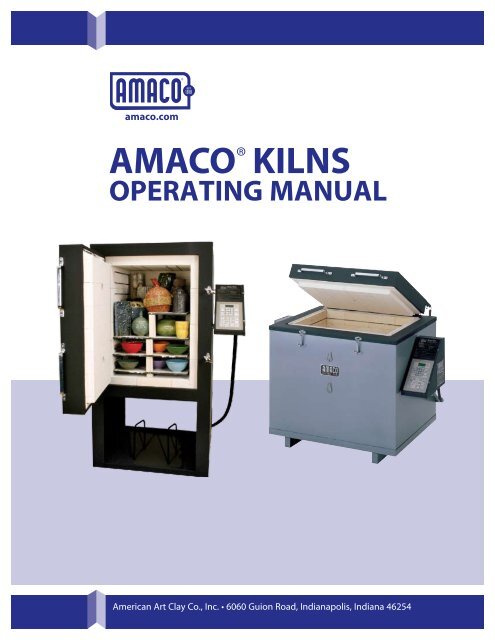
AMACO ® KILNS<br />
OPERATING MANUAL<br />
American Art Clay Co., Inc. • 6060 Guion Road, Indianapolis, Indiana 46254
Introduction<br />
Welcome<br />
You have selected your kiln after much deliberation, and<br />
this booklet is planned to assist you in its installation, operation<br />
and maintenance.<br />
All electric kilns sold by AMACO® are safe and well built.<br />
All AMACO® kilns are listed with Un der writ ers Lab o ra tories,<br />
Inc. You can be assured that the com plete unit—not<br />
just switch es and certain parts—has met their rigid standards<br />
for safe ty in regard to ca su al ty and fire haz ards.<br />
Most schools and in sti tu tions re quire the UL seal on all<br />
elec tri cal equip ment.<br />
Important: Read this entire manual before doing anything<br />
else. Whether you have owned an elec tric kiln before<br />
or not, please take the time to read this manual from<br />
cover to cover. We think even the most ex pe ri enced veteran<br />
will learn a few new tips.<br />
Limited Warranty<br />
All AMACO® kilns are guaranteed by AMACO® against defects<br />
in ma te ri als and workmanship to the original purchas<br />
er for a period of five years that covers parts and labor<br />
subject to these exclusions:<br />
Exclusions<br />
1. Damage due to misuse, including but not lim it ed to,<br />
over-firing, improper installation, rough han dling, improp<br />
er stacking, malfunction of cut offs and start ers.<br />
2. The KILN-SITTER® (if equipped) is sep a rate ly warrant<br />
ed by its manufacturer, W.P. Dawson, Inc.,<br />
6441 S. E.Johnson Creek Blvd., Portland, OR 97206,<br />
(503) 774-6000.<br />
3. Shipping damage.<br />
4. The warranty period has expired.<br />
5. Repair or service is done by an unauthorized dealer.<br />
6. Damage or failure due to acts of God such as, fire,<br />
flood, electrical storms, etc.<br />
7. Damage due to over-firing, reduction or salt glaz ing.<br />
8. Use for other than ceramic materials.<br />
9. Normal wear as experienced in the ceramic pro cess.<br />
10. Units modified in any manner.<br />
This warranty does not cover damage caused by failure<br />
of these in stru ments. The buyer’s sole and ex clu sive remedy<br />
shall be for the repair and/or re place ment of defective<br />
parts as provided herein. The buyer agrees that no<br />
other remedy (including, but not limited to, lost profits,<br />
lost sales, damage to property, or any other in ci den tal or<br />
consequential loss) shall be available to the buyer.<br />
Thank You!<br />
Congratulations! You’ve made a great choice from the proven AMACO® kiln line.<br />
Warranty Repair Instructions<br />
All warranty claims must be approved and serviced by an<br />
authorized AMACO® dealer. If there is not an authorized<br />
AMACO® dealer in your area, contact AMACO® directly for<br />
authorization, however labor costs will not be covered. If<br />
you exprience a problem with your equipment:<br />
1. Contact the dealer or representative from whom you<br />
made your purchase.<br />
2. If the dealer is unauthorized to perform repair or unable<br />
to correct the problem:<br />
a. Call the AMACO® Support Department toll free @<br />
1-800-374-1600 or 317-244-6871 (local).<br />
b. Email the AMACO/Brent Technical Support Department<br />
at technicalsupport@amaco.com<br />
3. Provide the following information and the Technical<br />
Support Agent will provide further assistance:<br />
a. Model number of item<br />
b. Serial number of item<br />
c. Voltage and phase of item<br />
d. Date purchased<br />
e. From whom purchased<br />
f. Nature of problem<br />
AMACO® recommends that all maintenance and repairs<br />
to kilns be performed by an Authorized AMACO® Service<br />
Technician, however if this is not possible AMACO®<br />
recommends that the owner work closely with our Technical<br />
Services representatives to ensure the diagnosis and<br />
repair are correct and performed safely. Normally, simple<br />
repairs can be made over the phone with our trained<br />
Technical Service Staff Monday–Friday 7:30 am–6:00 pm<br />
EST. If it is necessary to mail or ship parts to AMACO® for<br />
further inspection, parts must be sent prepaid. For your<br />
protection, insure all parts. The equipment and part serial<br />
number must accompany the defective item. Repair parts<br />
will be sent with a full refund on the invoice if examination<br />
confirms a de fect in materials or workmanship.<br />
If repairs must be made at the factory, it will be done at<br />
no charge for parts and labor provided all ship ping costs<br />
are supplied by the purchaser. Do not return any merchan<br />
dise without authorization. This warranty gives you<br />
specific legal rights. You may have other rights which vary<br />
from state to state.<br />
Your kiln is registered. We keep a per ma nent record of the<br />
serial number, model number and purchaser of every kiln<br />
sold. With this information, we can supply the necessary<br />
replacement parts for your par tic u lar kiln. Keep your papers<br />
in a safe place. You will want to refer to this instruction<br />
booklet, special kiln instructions, wiring di a gram and<br />
catalog. File them in a safe place for handy reference.
Quality Components of AMACO® <strong>Kiln</strong>s................................2<br />
Anatomy of AMACO® <strong>Kiln</strong>s.......................................................3<br />
Safety Information.................................................................. 4-5<br />
Electrical Requirements........................................................ 5-6<br />
When Your <strong>Kiln</strong> Arrives..............................................................6<br />
<strong>Kiln</strong> Location.................................................................................7<br />
<strong>Kiln</strong> Venting—Why It’s Important..........................................7<br />
Installing the Master KIln Vent................................................8<br />
Installing the KIln Vent—Suspended Version..............9-10<br />
Installing Multiple <strong>Kiln</strong> Vent Systems.................................10<br />
Test Firing....................................................................................11<br />
Getting Started..........................................................................11<br />
Loading Tips...............................................................................12<br />
Select Fire Control Features................................................13<br />
Select Fire Programming.............................................. 14-23<br />
General Information................................................. 14-15<br />
Choosing a Program........................................................16<br />
Programming Cone Fire Mode.....................................16<br />
Advanced Cone Fire Menu Features...........................18<br />
Programming Ramp/Hold Mode.................................18<br />
Advanced Features..........................................................19<br />
Running a Stored Ramp Hold Program.....................20<br />
Select Fire Menu Tree......................................................20<br />
Menu Features<br />
New Features.....................................................................21<br />
Programming Instructions..................................... 21-23<br />
Troubleshooting<br />
Preventative Maintenance.............................................24<br />
Table of Contents<br />
Troubleshooting Your <strong>Kiln</strong>.............................................24<br />
Select Fire Error Codes.......................................... 26-26<br />
Select Fire FAQ’s.............................................................27<br />
Select Fire Display Messages.....................................28<br />
<strong>Manual</strong> <strong>Kiln</strong> Operation..................................................... 29-36<br />
Preparation.........................................................................29<br />
Test Fire................................................................................29<br />
Pyrometric Cones.............................................................30<br />
Pyrometers.........................................................................30<br />
<strong>Kiln</strong>-Sitter®..........................................................................31<br />
Suggested Firing Schedules................................... 32-33<br />
Troubleshooting Guide............................................ 34-35<br />
Element Replacement.............................................. 35-36<br />
Switch Replacement........................................................36<br />
Heatwork.....................................................................................37<br />
Ceramic Defects and How to Avoid Them................. 38-42<br />
General Concepts.............................................................38<br />
Drying/Forming Cracks...................................................38<br />
Thermal Cracks/Dunts.....................................................39<br />
Glaze Fit/Crazing and Shivering...................................39<br />
Crazing.................................................................................39<br />
Shivering.............................................................................40<br />
Poor Glaze Adhesion.......................................................40<br />
Glaze Crawls.......................................................................40<br />
Over-Fired Ware................................................................41<br />
Under-Fired Ware..............................................................41<br />
Glaze Flowing Off the Piece..........................................42<br />
<strong>Kiln</strong> Accessories for AMACO® <strong>Kiln</strong>s............................... 43-45<br />
Table of Contents<br />
1
Quality Components That Make AMACO® <strong>Kiln</strong>s<br />
a Smart Choice<br />
Quality<br />
Select Fire Controller (if equipped)<br />
At the heart of your new<br />
kiln is the Select Fire<br />
con trol ler. This unit allows<br />
you much greater con trol<br />
over your kiln than ever<br />
before. It is es sen tial ly<br />
two con trol lers in one.<br />
You can fire by cone numbers<br />
or spec i fy your own<br />
firing profile with multiple<br />
ramps and holds.<br />
The wall mounted Select<br />
Fire is an option that<br />
functions in the same<br />
manner as the built-in version<br />
with the ex cep tion<br />
that it can be moved from<br />
one kiln to another. While<br />
the wall mounted version<br />
can not fire more than one<br />
kiln at a time, it can control<br />
any number of kilns a studio op er ates provided they<br />
have the same cord plug and re cep ta cle configuration.<br />
Brick<br />
AMACO® kilns are constructed<br />
of the fin est in sulat<br />
ing firebrick available<br />
today, offering strength,<br />
clean li ness and long life.<br />
All bricks are precision<br />
cut and grooved to assure<br />
tight fit, per fect element<br />
support and ease of re place ment. Because of<br />
their porous com po si tion, in su lat ing fire brick are fragile.<br />
Always handle your kiln and its brick with care. The<br />
brick in your kiln may begin to show some fine cracks<br />
after the first few firings, es pe cial ly after Cone 10 high<br />
firings. This is normal and does not harm the structural<br />
integrity of the kiln or im pair its func tion ing.<br />
Insulation<br />
The superior combination<br />
of insulated firebrick and<br />
block insulation means<br />
greater firing efficiency,<br />
lower radiant temperature,<br />
and lower electricity<br />
costs. AMACO® kilns are<br />
manufactured with up to<br />
8" of insulation keeping<br />
exterior heat radiation to<br />
a minimum, making them<br />
ideal for the classroom<br />
and any area where safety<br />
is a prime concern.<br />
Elements<br />
The highest quality iron-alu mi num-chro mi um (Kanthaltype<br />
A-1) element wire is used in all AMACO® kilns. El e<br />
ments are thoroughly test ed both before and af ter instal<br />
la tion for assured per for mance and even fir ing.<br />
Element life varies depending on whether the kiln will<br />
be primarily used for low fire bisque and greenware<br />
or high fire stoneware and porcelain (firing stoneware<br />
and porcelain requires a high fire rated kiln). As a general<br />
rule, elements last longer when used for low fire<br />
work than elements used for high fire work. Elements<br />
will last for many firings if treated care ful ly. Remember<br />
these points. 1. Keep the el e ment grooves free of debris:<br />
bits of bisque, glaze, cones, metal or high fire kiln wash<br />
will im me di ate ly fuse to an element and pro ceed to eat<br />
through it. El e ments be come brittle after repeated firings,<br />
so be ex treme ly careful not to break them. 2. Do<br />
not attempt to fire beyond the rating on your kiln.<br />
Easy-to-Change Element Connectors<br />
AMACO® kilns use corrosion<br />
resistant element lug<br />
connectors which allow<br />
for easy replacement of elements<br />
without having to<br />
cut wires and solder back<br />
together. All you need is a<br />
screwdriver to remove the<br />
element and re-connect<br />
the new one!<br />
2
Front-loading Models<br />
Door<br />
Handles<br />
Anatomy of AMACO® <strong>Kiln</strong>s<br />
Select Fire<br />
Computer<br />
Control<br />
Spring<br />
Door Latch<br />
and Handle<br />
Pyrometer<br />
Anatomy of AMACO® <strong>Kiln</strong>s<br />
<strong>Kiln</strong>-Sitter®<br />
Spring Door<br />
Latches<br />
Low/Medium/<br />
High Switches<br />
Insulating<br />
Fire Brick<br />
Built-in<br />
Stand with<br />
Dividers<br />
Power<br />
Cord<br />
Built-in<br />
Storage<br />
Cabinet<br />
AH-25 with Select Fire<br />
AH-10 shown with <strong>Kiln</strong>-Sitter® and Pyrometer<br />
(also available with Select Fire)<br />
Top-loading Models<br />
Lid Handles<br />
Insulating<br />
Fire Brick<br />
Fiber Gasket<br />
Spring Door<br />
Latches<br />
Peepholes<br />
with Covers<br />
Infinite<br />
Control<br />
Knobs<br />
Select Fire<br />
Computer<br />
Control<br />
Pyrometer<br />
HF-105 with Select Fire<br />
HF-101 shown with <strong>Kiln</strong>-Sitter® and Pyrometer<br />
(also available with Select Fire)<br />
3
Safety Information<br />
Tens of thousands of kilns are used safely in homes,<br />
schools, and professional studios throughout the world.<br />
With a good understanding of your kiln and a little common<br />
sense you can avoid any accidents. Please observe<br />
the following safety recommendations:<br />
Operation<br />
• AMACO® kilns are manufactured with up to 8” of insulation.<br />
At top temperature, the outside temperature of<br />
the kiln may reach up to 300 degrees. Be careful when<br />
working close to the kiln to avoid the possibility of severe<br />
burns. AMACO® recommends posting warning signs of<br />
this potential hazard in the kiln room.<br />
• Keep anyone who cannot understand warning signs<br />
such as small children and pets away form the kiln when<br />
it is firing.<br />
• Always use fire rated gloves when opening the kiln<br />
door while it is heated and keep un-protected skin and<br />
loose clothing away from the kiln.<br />
• DO NOT insert metal objects or any part of your body<br />
in the kiln when it is firing or when the power is still<br />
turned on to the kiln.<br />
• It is recommended to be present when the kiln is scheduled<br />
to complete firing.<br />
• DO NOT store any combustible material in the kiln room.<br />
In general, the kiln room should be clean and uncluttered.<br />
• Use IR and UV protective glasses when<br />
looking in the kiln during firing. Use #3<br />
welders green or gray glasses to protect<br />
your eyes.<br />
• Be cautious of intense heat around the peep holes<br />
when the covers are open.<br />
• In severe weather, disconnect your kiln from the power<br />
source. Electrical surges can damage the circuit board<br />
in the kiln’s controls.<br />
• <strong>Kiln</strong> lids on top loader styles are heavy, so make sure<br />
the kiln lid is raised at least 8” for the spring-balanced lid<br />
to be secure before releasing the lid.<br />
• Do not fire anything you are unsure of, certain items<br />
may explode, melt or release toxic fumes.<br />
• Never allow your kiln to exceed the temperature rating<br />
on the serial plate.<br />
• Do not unload the kiln before it reaches at least 150F.<br />
Use good quality gloves to remove hot ware to protect<br />
against burns and possible cuts from broken ware.<br />
• Always be sure to unplug the kiln before working on<br />
the electrical components. If the kiln is hard wired, turn<br />
off the circuit breaker.<br />
Installation<br />
• Use only properly sized and rated copper wire when<br />
installing the power supply for your kiln (see page 5).<br />
This work should be done by a licensed electrician.<br />
• <strong>Kiln</strong>s should always be located in a dry place to prevent<br />
electrical shock and corrosion (see page 7).<br />
Safety Information<br />
• Follow all instructions for installation in this manual,<br />
always observe fire, building and safety codes when installing<br />
any AMACO® product.<br />
• Take care to rate the sprinkler system high enough so<br />
it will not trigger when the kiln is at peak temp.<br />
• We recommend having a fire extinguisher<br />
rated for electrical fires easily accessible near<br />
the kiln.<br />
• AMACO® will not assume liability for injury or damages<br />
caused by variations from the instructions in this manual.<br />
• Ventilation is key to maintaining a healthy work environment<br />
and proper room temperature (see Venting,<br />
Why it is Important, page 7). Observe all installation information<br />
of the recommended kiln venting system. To<br />
ensure proper room temperature is maintained consult<br />
with a qualified HVAC professional.<br />
• Never use an extension cord.<br />
• Route the power cord in such a way as to not touch<br />
any part of the kiln. The kiln may get hot enough to melt<br />
the protective coating on the wire.<br />
• <strong>Kiln</strong>s get hot. Observe all instructions to<br />
ensure proper clearances from flammable<br />
or temperature sensitive objects and living<br />
things.<br />
• The proper placement of thermocouples is crucial<br />
to the proper operation of all automatically controlled<br />
kilns. Check all thermocouples for damage and correct<br />
placement. Thermocouples must protrude into the kiln<br />
chamber at least 2" to ensure an accurate reading.<br />
• Be careful of pinch hazards when working on or assembling<br />
the kiln.<br />
Maintenance<br />
• Disconnect the power source before performing any<br />
service to the kiln. Unplug or shut off power to the kiln if<br />
it will not be used for a long period of time.<br />
• Replace any electrical components that become discolored,<br />
brittle or corroded.<br />
• Use only AMACO® replacement parts. Improperly<br />
sourced parts can pose a hazard to your kiln and void<br />
the warranty.<br />
• Never modify your kiln without first consulting AMACO®.<br />
Precautions for the Select Fire Controller<br />
• The controller is a temperature control device. It is not<br />
a safety device.<br />
• The maximum operating temperature<br />
is 160˚F (71˚C) and the minimum temperature<br />
is 33˚F (1˚C). This temperature<br />
refers to the room temperature while<br />
the kiln is firing and does not pertain to<br />
the internal temperature of the kiln.<br />
4
• The controller contains static-sensitive parts that may<br />
be damaged by static electricity. Use caution to avoid<br />
creating static that may damage the equipment. In areas<br />
Most important to the proper operation of your new kiln<br />
is to make sure it has the correct power to operate. If wired<br />
correctly, your kiln will provide many years of excellent<br />
service. If the correct power requirements are not met,<br />
the first firing could be disappointing or even disastrous<br />
Electrical Requirements<br />
where static electricity is common, or during dry times of<br />
the year throughout the country, touch the kiln lid handle<br />
before touching the controller to discharge the static.<br />
for your kiln. The chart below lists the recommended electrical<br />
specifications for each kiln model. If there is uncertainty<br />
about the existing outlets, have them certified by a<br />
licensed electrician. If installing new receptacles provide<br />
this information to the electrician.<br />
Safety Information/<br />
Electrical Requirements<br />
Model Volts Amps Kilowatts Copper Wire<br />
Size*<br />
Fuse/Breaker<br />
Size<br />
NEMA<br />
Receptacle<br />
AH-30 240 3-phase 38.6 16.0 6 gauge 60 Direct Wire<br />
AH-25 240 1-phase 45.0 10.8 6 gauge 60 6-50<br />
240 3-phase 39.0 10.8 6 gauge 60 15-50<br />
208 1-phase 45.0 10.8 6 gauge 60 6-50<br />
208 3-phase 34.0 10.8 6 gauge 50 15-50<br />
AH-10 240 1-phase 30.4 7.3 6 gauge 40 6-50<br />
240 3-phase 17.6 7.3 6 gauge 40 15-50<br />
208 1-phase 35.1 7.3 6 gauge 50 6-50<br />
208 3-phase 22.1 7.3 6 gauge 40 15-50<br />
HF-105 240 1-phase 48.0 11.25 6 gauge 60 6-50<br />
240 3-phase 30.0 11.25 6 gauge 50 15-50<br />
HF-101 240 1-phase 37.5 9.0 6 gauge 50 6-50<br />
240 3-phase 24.0 9.0 6 gauge 40 15-50<br />
208 1-phase 43.0 9.0 6 gauge 60 6-50<br />
208 3-phase 25.0 9.0 6 gauge 40 15-50<br />
HF-97 240 1-phase 25.0 6.0 6 gauge 40 6-50<br />
240 3-phase 24.0 6.0 6 gauge 40 15-50<br />
208 1-phase 28.8 6.0 6 gauge 40 6-50<br />
208 3-phase 25.5 6.0 6 gauge 40 15-50<br />
EC-55 240 1-phase 27.1 6.5 6 gauge 40 6-50<br />
240 3-phase 16.5 6.5 6 gauge 30 15-50<br />
208 1-phase 28.7 6.5 6 gauge 40 6-50<br />
208 3-phase 16.5 6.5 6 gauge 30 15-50<br />
FA-44 240 1-phase 20.4 4.9 6 gauge 30 6-50<br />
240 3-phase 19.5 4.9 6 gauge 30 15-50<br />
208 1-phase 21.0 4.9 6 gauge 30 6-50<br />
208 3-phase 20.5 4.9 6 gauge 30 15-50<br />
FA-88 240 1-phase 25.0 6.0 6 gauge 40 6-50<br />
240 3-phase 24.5 6.0 6 gauge 40 15-50<br />
208 1-phase 28.8 6.0 6 gauge 40 6-50<br />
208 3-phase 25.5 6.0 6 gauge 40 15-50<br />
5
Electrical Requirements/<br />
When Your <strong>Kiln</strong> Arrives<br />
208 Versus 240 Supplies<br />
As you can see from the chart on the previous page,<br />
most AMACO® models are avail able in ei ther 208 or<br />
220/240 volt ver sions.<br />
The “120/208V” supply is increasingly en coun tered in<br />
schools and newly-built com mu ni ties be cause it’s more<br />
efficient for heavy 120V loads. This affects all AMACO®<br />
models because their elements receive the full 208 (or<br />
240) applied volts. The 240V versions of these kilns will<br />
usually low fire sat is fac to ri ly when moved to a 208V area.<br />
But the 208V ver sions should never be fired on a 240V<br />
supply with out first installing a full set of 240V elements.<br />
Oth er wise, all com po nents will be se ri ous ly overtaxed.<br />
NEMA Receptacle Guide<br />
UL and CSA Listed<br />
All AMACO® kilns are listed with Underwriters Laboratories,<br />
Inc. (UL). These seals are your assurance that the<br />
complete unit (not just the switches and certain parts)<br />
has met their rigid standards of safety with regard to<br />
casualty and fire hazards. The “cUL” is given to products<br />
listed with UL that meet the safety requirements of both<br />
Underwriters Laboratories and the Canadian Standards<br />
Association. All AMACO® kilns carry both of these symbols.<br />
AMACO® kilns are re-examined regularly, part by<br />
part, by both Underwriters Laboratories.<br />
6-50 15-50<br />
When Your <strong>Kiln</strong> Arrives<br />
Be present on kiln delivery so you can inspect the carton<br />
and contents for damage due to improper handling during<br />
shipping. Located on the bottom corner of the box<br />
is the SHOCK WATCH sticker and directions are provided<br />
on the outside of the box for using this program. The<br />
freight company is required to provide you with complete<br />
instructions to report any damage that occurred<br />
during shipping. It is important to note all damages to<br />
the kiln on arrival as the warranty will not cover damage<br />
due to shipping.<br />
The bill-of-lading covering this shipment is our receipt<br />
from the transportation company that the shipment was<br />
complete and in good condition when it left the factory.<br />
You should thoroughly inspect this shipment as soon as<br />
you receive it.<br />
Shortages and/or Visible Damage to Boxes<br />
A notation concerning any shortages of boxes or visible<br />
damage to the shipment should be made on both copies<br />
of the delivery receipt presented by the driver for the<br />
transportation company. If driver will not allow notations<br />
to be made to both copies, notify AMACO® directly.<br />
Concealed Damage or Shortage<br />
If, when your shipment is unpacked, any item from the<br />
order was omitted, promptly contact AMACO®. If the<br />
merchandise was damaged in transit, report this to the<br />
delivering carrier and request an inspection of the shipment.<br />
Unless you take this action, the transportation<br />
company will dispute their liability to any claim of lost<br />
or damaged merchandise. If the inspection request is<br />
denied, make an affidavit stating that you requested an<br />
inspection on a certain date and were denied an inspection.<br />
This, with other papers, will help support the claim<br />
and should be filed immediately. The responsibility for<br />
filing claims is with the person, school or company paying<br />
the freight bill. Save all packing materials. Don’t assemble<br />
or fire your kiln until your damage claim has been<br />
resolved. Fax or email a copy of the signed inspection report<br />
to AMACO®. Inspection reports MUST BE DATED NO<br />
LATER THAN 15 DAYS AFTER DELIVERY OF SHIPPMENT IN<br />
ORDER FOR CLAIM TO BE VALID. When this procedure is<br />
followed AMACO® makes every effort to assist in obtaining<br />
reparation.<br />
When your kiln is unpacked, check the metal nameplate<br />
to see that the voltage shown is the same as you ordered.<br />
If your electrician has not tested the power outlet<br />
to see that the specified current is available, he should<br />
do so before the kiln is installed. For example, too many<br />
appliances on a circuit will lower the available power<br />
and cause slow heating. THE BEST SOLUTION IS TO RUN<br />
A DIRCT LINE TO THE KILN.<br />
Prior to installation, your electrician will need the wiring<br />
diagram and instructions included in the kiln instruction<br />
folder that provide specific information about your particular<br />
kiln. This folder contains specific data, parts list,<br />
and firing instructions. Additional copies are available<br />
upon request.<br />
6
• Locate your kiln near your present electrical outlet or<br />
where a new circuit can be installed. Position the kiln to<br />
the left of your electrical outlet so the cord will have an<br />
easy run and will not place a strain on the plug or outlet.<br />
• Place the kiln in a room large enough to allow for adequate<br />
air flow and if the room is under 10' x 10', make<br />
sure there is a way for air to enter the room.<br />
• Install it in a well ventilated, sheltered area such as a<br />
garage, utility or hobby room. Allow a minimum 18<br />
inches (46 cm) of space between your kiln and adjacent<br />
walls, other kilns, shelving, etc. When multiple kilns<br />
will be installed in the same room, make sure the control<br />
boxes on the kilns are not facing adjacent kilns. Radiant<br />
heat from nearby kilns can damage the controller.<br />
• In front loading kilns, make sure there is adequate<br />
space for a service technician to access the back of the<br />
kiln. Warranty service will not be covered by AMACO® if<br />
adequate space for repairs and a safe working environment<br />
is not provided for service technicians.<br />
• For small rooms, monitor the firing so room temperature<br />
does not exceed 100˚F (38˚C). Do not fire if room<br />
temperatures are 32˚F (0˚C) or less as damage to the<br />
electronic components may result. Below is an example<br />
of a typical room layout.<br />
• Locate the kiln in a room with a bare cement floor. If a<br />
bare cement floor is not available, the uniform mechanical<br />
code requires two inches of masonry below the kiln<br />
extending a minimum of 12” (31 cm) beyond the outside<br />
circumference of the kiln.<br />
<strong>Kiln</strong> Location<br />
• Never fire your kiln within a four sided cabinet or closet.<br />
The fourth side must always be open to room air to<br />
prevent the kiln from overheating surrounding surfaces.<br />
It is best to leave at least two sides open for easy access<br />
to controls and peepholes.<br />
• When installing a kiln in a room with a fire control<br />
sprinkler system, do not place kilns within a 10 ft. (3m) radius<br />
below sprinkler heads. If this is not possible, contact<br />
AMACO® for alternative solutions before installing.<br />
• All kilns are vulnerable to the highly corrosive effects<br />
of marine air. If you live near salt water, locate the kiln<br />
indoors and protect it from the damp air.<br />
• Keep curtains, aprons, plastic or other flammable materals<br />
away from your kiln.<br />
Fan<br />
Shelving<br />
Example of Typical Installation<br />
<strong>Kiln</strong><br />
<strong>Kiln</strong><br />
18 "<br />
18 "<br />
18 "<br />
Master <strong>Kiln</strong> Vent<br />
18 "<br />
18 "<br />
<strong>Kiln</strong> Location/<strong>Kiln</strong> Venting—<br />
Why it is Important<br />
<strong>Kiln</strong> Venting—Why it is Important<br />
Safer Work Areas<br />
Successful firings and safe healthy work environments<br />
depend on clean circulated air in the kiln room as well<br />
and the firing chamber. It is recommended that all AMA<br />
CO® kilns use a direct, down draft venting system like the<br />
Master <strong>Kiln</strong>Vent (all AMACO® kilns) or the <strong>Kiln</strong>Vent Suspended<br />
Version (top loading AMACO® kilns only). These<br />
systems take the fumes from the kiln chamber, mix them<br />
with room air and vent them to an outside source, insuring<br />
that the gasses do not reach the work area. The<br />
venting systems will not reduce the temperature in the<br />
kiln and actually improve the uniformity of the kiln firing<br />
by increasing the circulation inside the chamber. Cooldown<br />
time is reduced by 2-4 hours often allowing firing<br />
the very next day.<br />
Testing has shown that gasses generated by the use of<br />
unvented kilns exceed OSHA levels for carbon monoxide<br />
and should be removed from the kiln room. The AMA<br />
CO® kiln vent systems effectively mix hot gas from the<br />
kiln with room air to provide a cool exhaust that is safely<br />
vented outdoors. In addition to making the kiln room<br />
more comfortable, accidental burns and jarring of the<br />
ware are reduced because the lid stays closed throughout<br />
the firing.<br />
Better Finished Results<br />
Down draft, direct venting systems produce truer colors,<br />
uniform firings and less glaze flaws.<br />
1) Carbon monoxide is reduced while adding oxygen<br />
for reds, greens, gold and yellows. Colors are brighter<br />
and more vibrant and different colors can be fired at the<br />
same time.<br />
2) Venting also produces more even firings and uniform<br />
colors by circulating the hot gasses. The items on the bottom<br />
of the kiln receive the same heat as items on the top.<br />
3) Providing oxygen in the kiln chamber helps to burn<br />
out carbon and organic compounds in the clay body, reducing<br />
pinholes, glaze craters, and bubbles.<br />
7
Installing the Master <strong>Kiln</strong>Vent<br />
Installing the Master <strong>Kiln</strong>Vent<br />
The Master <strong>Kiln</strong>Vent can be used for all AMACO® front<br />
and top loading square kilns to vent gasses from the<br />
kiln to the outside via flexible metal ducting. It can be<br />
mounted to both side, bottom or top of all AMACO® front<br />
loading kilns. or in the center or bottom of all AMACO®<br />
top loading kilns.<br />
B<br />
A<br />
E<br />
A. High temperature hose with clamp<br />
B. Blower/motor with 6' power cord<br />
C. Collection cup<br />
D. Adjustable height foot/coupling nut/wing nut<br />
E. Gasket<br />
Not shown—additional parts and tools required (not<br />
supplied with vent):<br />
(4) #10 3 /4" sheet metal screws<br />
(4) #10 1" dry wall screws<br />
4" Dia. flexible metal ducting (60’ maximum)<br />
6" or longer 1 /4" diameter drill bit<br />
(use 10" long, 1 /4" diameter drill bit for AH-30)<br />
Electric drill<br />
Flat head screwdriver<br />
Phillips head screwdriver<br />
Vacuum cleaner<br />
D<br />
C<br />
1. AMACO® kilns are pre-drilled to accept the Master<br />
<strong>Kiln</strong>Vent.<br />
2. Place insulation piece provided in kit over connector<br />
cup and mount cup centered over hole configuration<br />
with 3 /4" sheet metal screws. Screws will enter directly<br />
into metal outer shell of kiln.<br />
3. Connect high temperature hose to connector cup using<br />
hose clamps provided, with flat head screwdriver.<br />
4. Connect black high temperature hose to Master <strong>Kiln</strong><br />
Vent motor/blower with hose clamps provided. IMPOR-<br />
TANT: Cover extra high temperature receptacle if not<br />
venting two kilns.<br />
5. Master <strong>Kiln</strong>Vent motor can be mounted to the wall,<br />
stored in underside of kiln stand or placed on top of kiln.<br />
6. If mounting Master <strong>Kiln</strong>Vent motor to wall, use 1" sheet<br />
rock or appropriate screws.<br />
7. Attach 4" ducting to motor exhaust receptacle using<br />
hose clamps (not provided) and vent to outside source<br />
or existing ducting if under 60 feet. DO NOT have more<br />
than four 90° bends in ducting.<br />
8. Vacuum any brick dust that was generated during<br />
drilling.<br />
Note: While the AMACO® vents are key to creating safe<br />
work environments and better work, these systems will<br />
not reduce the kiln temperature or the ambient heat the<br />
kiln radiates into the room. The kiln room area must be<br />
adequately sized and exhausted to keep the space under<br />
100°F during peak temperatures and at least 18 inches<br />
of clearance must exist around all sides of the kiln. Sprinkler<br />
systems in kiln area should be rated so that they will<br />
not trigger when the kiln is at peak temperature.<br />
8
This <strong>Kiln</strong>Vent is primarily designed to be used with AMA<br />
CO® top loading kilns. The unit is tightly suspended on the<br />
bottom of the kiln using the hooks and springs provided.<br />
B<br />
C<br />
Installing the <strong>Kiln</strong>Vent—Suspended Version<br />
H G F<br />
A. Plenum<br />
B. Blower/motor with 6' power cord<br />
C. Blower adapter<br />
D. (2) 6" drill bits ( 1 /4" and 5 /32" dia.)<br />
E. 4" flexible aluminum duct (8' long)<br />
F. (2) springs (8" and 15" long)<br />
G. (3) hooks and (3) 5 /8" sheet metal screws<br />
H. 4" hose clamp<br />
Preparing the <strong>Kiln</strong><br />
Be sure that your kiln has been prepared by drilling ventilation<br />
holes according to the directions in your <strong>Kiln</strong><br />
Vent owners manual.<br />
Installing the Rear Hooks (for spring)<br />
• Mark two points, 3 1 /2" up from the bottom of the kiln<br />
and 4" right and left of the center of the kiln as shown<br />
in figure 1:<br />
E<br />
D<br />
H<br />
A<br />
Attaching the <strong>Kiln</strong>Vent<br />
The <strong>Kiln</strong>Vent comes with a long spring (15") and a short<br />
(8") spring.<br />
• Attach the short spring to the front of the metal plenum<br />
by hooking the open end of the spring into the<br />
small hole located at the bottom front. (See figure 2.)<br />
• Place the <strong>Kiln</strong>Vent assembly under the kiln with the<br />
motor to the rear and facing up. Locate it so the angle on<br />
the plenum will rest up against the rear of the kiln. The<br />
fiberglass gasket will be between the kiln and <strong>Kiln</strong>Vent.<br />
The gasket will provide a seal and minimize vibration<br />
of the kiln. Make sure the plenum is aligned so that the<br />
holes in the bottom of the kiln floor are over the opening<br />
in the <strong>Kiln</strong>Vent and gasket.<br />
• Attach one end of the long (15") spring to one of the<br />
hooks. Holding the plenum up against the kiln, pull the<br />
spring under the plenum and attach it to the other hook.<br />
(See figure 2).<br />
15"<br />
Spring<br />
Sheet Metal Screws<br />
and Hooks<br />
Back Side<br />
of <strong>Kiln</strong><br />
Plenum<br />
8" Spring<br />
Gasket<br />
Figure 2<br />
Installing the <strong>Kiln</strong>Vent—<br />
Suspended Version<br />
3 1 ⁄2"<br />
4"<br />
Rear View<br />
8" Figure 1<br />
• Drill a hole in the metal using the smaller of the two<br />
drill bits provided ( 5 ⁄32")<br />
• Attach two of the hooks using the sheet metal screws<br />
provided.<br />
Installing the Front Hook (for spring)<br />
• Mark a point that is 3 5 ⁄32" up from the bottom of the<br />
kiln and centered left to right.<br />
• Drill a hole in the sheet metal using the small drill<br />
bit ( 5 ⁄32").<br />
• Attach the remaining hook using the sheet metal<br />
screw provided.<br />
• The front of the metal plenum should be under the<br />
kiln with the small (8") spring attached. If the spring is<br />
not attached to the metal plenum, do this now.<br />
• Pull the spring and attach it to the hook on the front of<br />
the kiln.<br />
• Adjust the metal plenum at the rear so that it rests flush<br />
with the back and bottom of the kiln.<br />
• No gap should exist between the bottom of the kiln<br />
and the top of the metal plenum. It is important that the<br />
gasket around the plenum hole be flush against the kiln<br />
bottom. If it is not, call AMACO®. We can provide an adapter<br />
kit which can seal up to 1 1 ⁄2".<br />
Installing the Flexible Ducting<br />
Place the clamp over the 4" dryer ducting and install the<br />
ducting on the <strong>Kiln</strong>Vent at the end of the output tube.<br />
The ducting should go on the outside of the tube adapter.<br />
Use the clamp provided to hold the ducting in place.<br />
Install the dryer vent flap using the instructions provid<br />
9
Installing the <strong>Kiln</strong>Vent—Suspended<br />
Version/Multiple <strong>Kiln</strong>vent Systems<br />
ed by the manufacturer and with attention to your local<br />
and state codes and regulations.<br />
Once the dryer flap vent is installed, carefully stretch<br />
the flexible aluminum ducting and clamp it to the flap<br />
vent tube. When stretching the ducting, avoid sharp 90°<br />
bends (gentle, 45º bends are recommended) and do not<br />
twist or compress the ducting. Up to 60' of ducting containing<br />
4 bends may be safely used with no drop in static<br />
air flow at the duct exhaust point or reduction in draw at<br />
the kiln. Seal any connections or punctures with silicone<br />
sealant or wrap with duct tape.<br />
Finishing Installation<br />
Attach the Reminder Tag to your kiln on the switch box<br />
where it will always be seen before firing. Plug the <strong>Kiln</strong><br />
Vent into a standard 120V outlet. Operate the switch to<br />
check out blower operation.<br />
You are now ready for your first test firing. Refer to the<br />
kiln owner’s manual or <strong>Kiln</strong>Vent for recommendations<br />
using the test cones provided.<br />
Note: While the AMACO® vents are key to creating safe<br />
work environments and better work, these systems will<br />
not reduce the kiln temperature or the ambient heat the<br />
kiln radiates into the room. The kiln room area must be<br />
adequately sized and exhausted to keep the space under<br />
100°F during peak temperatures and at least 18 inches<br />
of clearance must exist around all sides of the kiln. Sprinkler<br />
systems in kiln area should be rated so that they will<br />
not trigger when the kiln is at peak temperature.<br />
Installing Multiple <strong>Kiln</strong>Vent Systems<br />
If you have the Master <strong>Kiln</strong>Vent with Expansion Kit or<br />
more than one AMACO® <strong>Kiln</strong>Vent—Suspended Version,<br />
you can install them individually or connect each unit<br />
to a central duct to remove the gases. For best air flow,<br />
a 45° elbow should be used. The recommended central<br />
duct diameter is 6" for two <strong>Kiln</strong>Vent Systems, 8" for three<br />
or four systems, and 10" for five or six <strong>Kiln</strong>Vent Systems.<br />
Two kiln ventilation systems can be vented to a single<br />
exhaust point using a “Y” adaptor. However, a damper<br />
should be installed in each duct line and left closed<br />
when that ventilation system is not in use. See illustration<br />
below:<br />
4" duct from<br />
<strong>Kiln</strong>Vent #1<br />
closed damper<br />
8" central duct to outside<br />
4" duct to outside<br />
4" duct from <strong>Kiln</strong>Vent #1<br />
4" duct from <strong>Kiln</strong>Vent #2<br />
4" duct from <strong>Kiln</strong>Vent #3<br />
45º<br />
elbow<br />
4" duct from<br />
<strong>Kiln</strong>Vent #2<br />
"Y"<br />
adaptor<br />
open damper<br />
10
Once appropriately installed, the kiln is ready for the test<br />
fire. Test firing is important to operation of the kiln as it<br />
will help to identify any installation errors that may have<br />
occurred, burn off the protective coating on the elements,<br />
and properly oxidize them to maximize their life.<br />
Preparations before test fire<br />
Vacuum out the kiln to remove dust and packing material<br />
that may be present from shipping.<br />
Prep all shelves. Wipe clean all new shelves with a damp<br />
sponge. Mix AMACO® <strong>Kiln</strong> Shelf Wash (supplied) with<br />
water, to the consistency of whole milk, then apply three<br />
even coats to shelves and let dry. Apply <strong>Kiln</strong> Shelf Wash<br />
to one side of the shelves and leave a ¼ margin from the<br />
outside edge of the shelf. Never use <strong>Kiln</strong> Shelf Wash on<br />
the interior of the kiln.<br />
Test Firing<br />
Follow the loading guidelines on page 12 without ware.<br />
Place Orton Self Supporting cones on each shelf, staggering<br />
the placement to ensure full kiln temp test coverage.<br />
Test Firing<br />
Select Fire Models<br />
If your kiln is equipped with the Select Fire, refer to<br />
page 16 (Programming Cone Fire Mode) and program<br />
the kiln for a cone 04 medium speed test fire with no<br />
hold and no preheat. The kiln should complete firing in<br />
approximately 8 hours.<br />
Models with Infinite Control Switches<br />
If your kiln has infinite control switches and Dawson<br />
<strong>Kiln</strong>-Sitter®/Limit Timer, refer to page (29) to complete a<br />
Cone 04 fast speed cone<br />
fire test which takes approximately<br />
8 hours.<br />
Once the test fire is complete<br />
and kiln has cooled<br />
check that the cones<br />
have all bent correctly.<br />
Your kiln is now ready to<br />
fire work!<br />
Getting Started/Test Firing<br />
Getting Started<br />
This page is a memory aid, not a substitute to reading and<br />
understanding the manual.<br />
Activate the power source by plugging in the kiln or controller.<br />
After plugging in the kiln, the display will read<br />
WAIT for approximately 10 seconds while power is restored<br />
to the kiln. It will then switch to Idle Mode. In Idle<br />
Mode the display will flash the kiln temperature alternating<br />
with IdLE. Begin all programming in Idle Mode.<br />
Be sure the programmer is set to the right temperature<br />
scale before proceeding (Fahrenheit or Celsius).<br />
Cone Fire Mode<br />
Step 1 – Press CONE FIRE.<br />
Step 2 – Input PREHEAT time. Press ENTER.<br />
Step 3 – Input Cone number. Press ENTER.<br />
Step 4 – Input a SPEED. Press ENTER.<br />
Step 5 – Input HOLD time. Press ENTER.<br />
Step 6 – Press START.<br />
Ramp Hold Mode<br />
Step 1 – Press RAMP/HOLD.<br />
Step 2 – Input the PROG number. Press ENTER.<br />
Step 3 – Input the number of segments. Press ENTER.<br />
Step 4 – Input the first heatng rate. Press ENTER.<br />
Step 5 – Input the first temperature to reach. Press ENTER.<br />
Step 6 – Input HOLD time. Press ENTER.<br />
Step 7 – Repeat steps 4 through 6 until alarm flashes.<br />
Press ENTER.<br />
Step 8 – Press START.<br />
Important: To effectively use Ramp/Hold mode, it is imperative<br />
to understand heat-work theory. If you know<br />
the theory well, and if you have had experience with<br />
other programmable kilns or controllers, then the Quick<br />
Start instructions will be use ful.<br />
If not, please read the complete Ramp/Hold in struc tions<br />
beginning on page 16 and page 18 for de tails.<br />
The Ramp/Hold Mode can be used for all fir ing ap pli cations<br />
including glass and, in high fire kilns, por ce lain and<br />
stone ware. This op tion al lows you to cre ate your own<br />
pro files with up to six ramp and hold seg ments. A segment<br />
has three com po nents: heat ing rate, tem per a ture<br />
and hold. It is easy to pro gram. Be sure to see page 37 for<br />
in for ma tion on heat work.<br />
11
Loading Tips<br />
Loading Tips<br />
Balance the Load<br />
When planning how to load your kiln, keep in mind that<br />
the center of the kiln is generally the hottest. Therefore,<br />
you will want to distribute the load with the larger, thicker<br />
pieces towards the middle and the smaller, thinner<br />
pieces towards the top and bottom. In addition, if half<br />
your load consists of small, heavy pieces and the other<br />
half is large, thin-walled pieces, don’t group them all in<br />
one section. Mix them so there is a balance of each type<br />
throughout the kiln.<br />
Allow the <strong>Kiln</strong> to Breathe<br />
Many studios work with glazes that require oxygen<br />
to develope properly. Providing adequate space between<br />
pieces allows the kiln to “breathe”. If the firing<br />
chamber of your the is larger than 18" x 18", the<br />
recommended furniture kit will contain smaller (half)<br />
shelves for staggered shelf configurations. Allowing a<br />
minimum ¼" gap between half shelves will increase<br />
the flow of oxygen in the firing chamber, especially<br />
when using a kiln vent system.<br />
Allow for Proper Clearances<br />
<strong>Kiln</strong>s lose most of their heat from the lid/door. Ideally,<br />
there should be at least two inches of space between<br />
the lid and the nearest piece. DO NOT SET PIECES DI-<br />
RECTLY ON THE KILN FLOOR. Place a shelf on 1" posts<br />
on the floor of the kiln. For best results, ware should<br />
not be placed within 1" of an element. Large flat<br />
pieces like plates should have their rims positioned<br />
between two elements. When using an AMACO® <strong>Kiln</strong>vent<br />
System, the vents or “peepholes” in the front of<br />
the kiln allow air to be drawn into the firing chamber.<br />
Avoid placing ware directly under one of these holes,<br />
as this could create flaws in the glaze.<br />
DO NOT crowd the <strong>Kiln</strong>-Sitter® or<br />
Thermocouple<br />
Keep shelves at least ¼” from the sensing rod, and<br />
ware at least ½” away. If your load should shift during<br />
firing there will be less danger of jamming the <strong>Kiln</strong>-<br />
Sitter® or having ware resting against the thermocouple<br />
causing inaccurate temperature readings or damage<br />
to the ware.<br />
DO NOT load damp ware into your <strong>Kiln</strong><br />
Make sure all the ware is bone dry before loading it into<br />
the kiln. It should feel close to room temperature—if it<br />
feels colder, water is still evaporating from it.<br />
DO NOT Rush<br />
Take the time to properly load the kiln. Dropped ware<br />
or shelves can cause damage. Take special care to protect<br />
the bottom elements on kiln models that have<br />
them. Check each piece to insure that excessive glaze<br />
or an unsteady placement will not cause problems<br />
during the firing. A few extra minutes could save a lot<br />
of frustration.<br />
Top<br />
Loading<br />
<strong>Kiln</strong><br />
Front<br />
Loading<br />
<strong>Kiln</strong><br />
12
Select Fire Control Features<br />
(if equipped)<br />
Digital Readout<br />
Shows prompts, messages and tem per a ture<br />
throughout firing and cool down.<br />
Select Fire Control Features<br />
Touchpad<br />
Smooth surface pads are<br />
easy to clean and have<br />
no moving parts.<br />
Menu<br />
Lets you accesses menu<br />
diagnostics feature and<br />
advanced settings.<br />
Delay Option<br />
Lets you delay start of<br />
firing for convenient<br />
operation.<br />
Alarm<br />
You can set alarm<br />
to sound at any<br />
tem per a ture.<br />
Action Controls<br />
Lets you start or stop kiln<br />
operation.<br />
Ramp/Hold Mode<br />
Lets you select up to eight<br />
segments of tem per a ture<br />
change and hold.<br />
Cone Fire Mode<br />
Lets you fire by simply<br />
en ter ing the desired<br />
Cone number.<br />
View Current Segment<br />
Shows you what<br />
Ramp/Hold segment the<br />
kiln is currently in.<br />
Firing Speeds<br />
Choose from Slow,<br />
Medium or Fast heat ing.<br />
Cone Table<br />
Converts Cone numbers<br />
to temperature.<br />
Review<br />
Reviews your current<br />
firing program.<br />
13
General Select Fire Programming Information<br />
Programming<br />
The LED Display<br />
The display shows 4 characters and 14 segments per character.<br />
This is not always enough to exactly represent the message<br />
presented. If you find you do not understand a message,<br />
consult the Display Messages section of this manual.<br />
The controller may be programmed in either Celsius or<br />
Fahrenheit. It is very important to know which temperature<br />
scale it is using. If there is a LED illuminated in the<br />
lower right hand corner of the display, the temperature<br />
scale is set to Celsius. Refer to the MENU section of this<br />
manual to change scales if necessary.<br />
When prompted to enter time values, there will be an LED<br />
illuminated in the lower center portion of the display. We<br />
refer to this as a decimal point. Everything to the left of<br />
the decimal will be hours and everything to the right will<br />
be minutes.<br />
Idle Mode<br />
When the kiln is flashing IdLE alternately with the current<br />
temperature of the kiln chamber we refer to the controller<br />
as being in Idle Mode. This simply means that the kiln is<br />
ready to be programmed. To return to Idle mode you may<br />
press STOP at any time.<br />
Start/Stop/Enter<br />
The START key begins the program which is currently<br />
loaded in memory. It may only be accessed when the kiln<br />
is in Idle Mode. The STOP key will turn off the kiln at any<br />
point of a program. It may also be used to return to Idle<br />
Mode in the middle of entering a program. ENTER must<br />
be pressed after entering any time, temperature or programming<br />
speed. ENTER is also used to turn an Alarm off<br />
that has sounded during a firing.<br />
Delay<br />
The Delay feature allows you to program, the kiln to automatically<br />
start at a future time. This feature is primarily used<br />
to take advantage of better off-peak electric rates or to time<br />
the shutoff of the kiln for a time that is convenient for you<br />
to be there. It can be set for a Ramp Hold Mode or Cone Fire<br />
Mode program and can be accessed only after the program<br />
has been entered and the controller is in Idle Mode. You<br />
can enter a delay time up to 99 hours and 99 minutes.<br />
From Idle Mode, press DELAY<br />
Input Delay time in hours and minutes, then press ENTER<br />
When START is pressed to begin the program, the time<br />
entered for the delay will reappear on the screen and begin<br />
counting down. When it reaches 00.00 the kiln will<br />
start the program currently loaded. The Delay time will<br />
stay in memory until it is cleared. To clear it, follow the<br />
instructions for entering a Delay and enter 00.00 for the<br />
Delay time.<br />
Alarm<br />
The Alarm feature is used to sound an alarm at a specific<br />
temperature in the program. This feature is primarily used<br />
to prompt the user to lower a propped lid or for glass artists<br />
to look into the kiln at peak temperature. It can be set<br />
for a Ramp Hold or Cone Fire program. You can enter any<br />
Alarm temperature between 0 and the maximum temperature<br />
rating of the kiln.<br />
From Idle Mode, press ALARM<br />
Input Alarm Temperature, then press ENTER<br />
When START is pressed the program currently loaded<br />
will begin. When the temperature of the kiln reaches<br />
the Alarm temperature entered, the Alarm will sound in<br />
a series of beeps. Press ENTER to turn off the Alarm. DO<br />
NOT press STOP—this will stop the program. The Alarm<br />
temperature will stay in memory until it is cleared. To clear<br />
it, follow the instructions for entering an Alarm and enter<br />
9999 for the Alarm Temperature. “9999” is the default for<br />
having the Alarm off.<br />
Menu<br />
The Menu features are discussed in depth in the Menu<br />
Features section of the manual.<br />
Review<br />
The Review key allows the user to look at the current<br />
program loaded to make sure it is correct. We highly suggest<br />
using this feature to check programs prior to each<br />
firing. Press REVIEW and the display will step through<br />
each segment of the program for a Ramp/Hold program.<br />
14
It will also let you know if there are Alarm temperatures or<br />
Delay times entered and whether or not the Error Codes<br />
feature is ON or OFF. Below is a sample Review of a Cone<br />
Fire program.<br />
Sample Cone Fire Review<br />
1. Cone 04 Cone Number<br />
2. F 1920 Actual temperature when kiln shut off<br />
3. SPD FAST Cone fire speed<br />
4. HOLD 0.00 Length of hold at top temperature<br />
5. PRHT 0.00 Preheat time (Will only be displayed if<br />
preheat is set to ON)<br />
6. DELA 0.00 Delay Time<br />
7. ALRM 9999 Alarm Temperature<br />
8. ERCD ON Error Codes on or Off<br />
View<br />
The View key allows you to determine what segment of a<br />
Ramp/Hold program the controller is currently running.<br />
While a Ramp/Hold program is firing press VIEW. The<br />
display will show the current segment, the traveling set<br />
point, and the circuit board temperature. The segment<br />
number is prefixed by either “RA” (Rate) or “HLd” to indicate<br />
whether the kiln is heating (or cooling) or holding<br />
temperature. The traveling set-point indicates the target<br />
temperature of that segment.<br />
Cone Table<br />
The Cone Table key allows the user to look up the temperature<br />
equivalent of Cone values. To use simply press<br />
Cone Table from Idle Mode, enter a cone value and press<br />
ENTER . This key may also be used to insert a Cone Value<br />
for the peak temperature of a Ramp and Hold program.<br />
This Cone Value will be automatically adjusted (Cone<br />
Correlation) based on the performance of the kiln. To<br />
use this feature press Cone Table when prompted to enter<br />
the peak temperature of your program, enter a Cone<br />
value and press Enter.<br />
During the Firing<br />
You will see the internal temperature of the kiln displayed<br />
as the temperature increases. The options available<br />
during the firing are:<br />
• Review program at any time.<br />
• View Current Segment of RAMP/HOLD Program.<br />
• Press Stop to interrupt a firing for any reason.<br />
Note it is common to see smoke come out of your kiln on<br />
the first firing. This is normal; the elements are burning<br />
off a coating.<br />
After the Firing<br />
• When completed, the display will show “CPLt” alternately<br />
with the firing time in hours and minutes and<br />
the current temperature of the kiln. Press ENTER to return<br />
to Idle Mode.<br />
• When a Cone Fire Mode program (or a Ramp and Hold<br />
program which uses the Cone Correlation feature) is<br />
run, the controller may alter the peak temperature of<br />
the program based on the kilns ability to achieve the<br />
final temperature rate. This is done to insure the heatwork<br />
remains constant. If you are interested in knowing<br />
if that temperature changed, press REVIEW after<br />
the program is complete. This temperature value will<br />
only appear in a review once after the firing so be sure<br />
to pay attention.<br />
• Allow the kiln to cool naturally. Never unplug additional<br />
peepholes or post the lid until the ware is cool<br />
enough for barehanded unloading, about 130˚F (54˚C).<br />
• When unloading, be sure to examine the self-supporting<br />
cones on the shelf to determine if the kiln is<br />
firing correctly.<br />
• It is not necessary to unplug the kiln when not in use<br />
(unless severe storms are expected). Continuous plugging<br />
and unplugging may cause components in the<br />
plug and receptacle to loosen up over time. Loose components<br />
in electrical connections create heat and can<br />
pose a fire hazard.<br />
Fine Tuning Your <strong>Kiln</strong><br />
If after inspecting your witness cones you find that the<br />
kiln fired a little hot, a little cold, or a little uneven, there<br />
are certain things you can do to fine tune the kiln before<br />
your next firing. Always be sure you use self supporting<br />
108˚F (42˚C) witness cones. Cones should be placed about<br />
2 inches (4.8 cm) from the kiln wall and or thermocouple.<br />
Never place cones directly on the bottom slab.<br />
Too Cool<br />
Add more Hold Time to a Cone Fire program. If the target<br />
cone did not bend at all, try adding 15 minutes to the Hold<br />
Time. If the Cone has started to bend, add time in 5 minute<br />
increments. If hold times begin exceeding 30 minutes<br />
contact AMACO® or your distributor for more information.<br />
Too Hot<br />
If the Cone is knuckled down on the shelf, reduce the<br />
Hold Time by 15 minutes. If the tip of the Cone has just<br />
started to touch the shelf, reduce Hold Time in 5 minute<br />
increments. If hold times are already set to zero, contact<br />
AMACO® or your distributor for more information.<br />
Thermocouples drift towards an over fire as they age so<br />
if the problem persists or requires excessive changes to<br />
correct, it may be time to change the thermocouple.<br />
Uneven Heat Distribution<br />
Venting systems such as the AMACO® Master <strong>Kiln</strong>Vent or<br />
<strong>Kiln</strong>Vent—Suspended Version help with uneven heating<br />
by mixing the air within the kiln chamber.<br />
Programming<br />
15
Choosing a Program<br />
Programming<br />
The first step in programming your kiln is to decide which<br />
“Programming Mode” to use. Before making this decision<br />
it helps to have a good understanding of Firing Programs.<br />
A Firing Program consists of a series of program segments.<br />
Each segment consists of a Rate, a Temperature<br />
and a Hold Time. These segments determine the rate at<br />
which the kiln will heat up or cool down and how much<br />
Heatwork the pieces in the kiln will receive. For more information<br />
on Heatwork see page 37.<br />
Cone Fire Mode<br />
With Cone Fire Mode the programs are written for you.<br />
You simply give the controller some key information regarding<br />
the pieces you are firing and it accesses a program<br />
which best suites your project. This is the most commonly<br />
used mode of programming. The programs were<br />
created by Ceramic Engineers and are designed to minimize<br />
problems that can occur during critical stages in the<br />
firing process.<br />
Cone Fire Mode is incredibly easy to use however, the<br />
software itself is extremely advanced. Cone Fire Mode<br />
uses complex algorithms to simulate the heatwork of a<br />
Pyrometric Cone. What is impressive is that it automatically<br />
makes adjustments to the firing profile based on<br />
your kilns performance. Cone values are based on heatwork<br />
and heatwork is a function of time and temperature.<br />
Therefore, if your kiln is firing slow due to a heavy load or<br />
aging elements, Cone Fire Mode automatically adjusts the<br />
peak temperature down so you get the perfect amount<br />
of heatwork. There are very few reasons not to use this<br />
mode of programming.<br />
RAMP/HOLD Mode<br />
RAMP/HOLD Mode allows you to write your own programs<br />
when the results you want cannot be achieved<br />
through Cone Fire Mode. It is a perfect tool for:<br />
• Fusing and slumping glass<br />
• Annealing metal and glass<br />
• Firing Precious Metals<br />
• Clay<br />
• Specialized glaze formulations and techniques<br />
Ramp/Hold is generally considered an advanced form of<br />
programming. It requires in-depth knowledge of heatwork<br />
and a good feel for how your kiln performs under a<br />
range of conditions. Below is an example of a simple glass<br />
fusing Ramp/Hold program.<br />
Programming Cone Fire Mode<br />
Programming Steps<br />
Step 1 – From Idle Mode. Press CONE FIRE. Display will<br />
read PRHT alternately with 00.00.<br />
Step 2 – Input a PREHEAT TIME IN HOURS AND MIN-<br />
UTES. Press ENTER. (See page 23 for more information<br />
on Preheat.) Display will read CONE alternately with the<br />
last Cone Value entered.<br />
Step 3 – Input a CONE VALUE. Press ENTER. Display will<br />
read Spd alternately with the last Speed entered.<br />
Step 4 – Press a SPEED (SLOW, MED or FAST). Press<br />
ENTER. Display will read HOLD alternately with a Hold<br />
time value.<br />
Step 5 – Input a HOLD TIME if one is desired. Press EN-<br />
TER. Display will flash CPL, then will return to Idle Mode.<br />
At this point the program is loaded and ready to start.<br />
Before pressing START, it is a good idea to press REVIEW<br />
to make sure the program was input correctly. Also, verify<br />
that the lid latch is engaged if your kiln is equipped<br />
with a lid lifter and check to see the area is clear of all<br />
combustible materials.<br />
Step 6 – Press START. Display will read -ON- briefly and<br />
then display the current temperature of the kiln. If a delay<br />
start has been entered the display will begin counting<br />
down the time entered.<br />
When the firing is complete the display will read CPLT alternately<br />
with the current temperature of the kiln and the<br />
time it took to complete the program. To clear this data<br />
and return to Idle Mode and press ENTER.<br />
16
Decription<br />
Step 1 – Cone Fire<br />
The Cone Fire Mode runs a factory installed multi-segment<br />
program which is selected based on the Cone Value,<br />
Speed, and Hold time you choose. Below is an example of<br />
a program which is run if you choose a Cone Value of 04, a<br />
Speed of Medium and Hold time of 5 minutes.<br />
One of the greatest features of Cone Fire Mode is Cone<br />
Correlation. It automatically measures the rate of firing<br />
during the last hour of the heating program and adjusts<br />
the final temperature based on the observed firing rate.<br />
This will insure consistent results as the kiln elements become<br />
weaker with normal wear from repeated firing. As a<br />
result the shutoff temperature may vary between firings.<br />
heat some pieces too quickly, they can crack or explode.<br />
There are three available speeds to choose from. Below is<br />
a description of each speed along with a graph showing<br />
the firing profile:<br />
Cone Fire – Slow<br />
Slow Speed will take approximately 12 hours to complete.<br />
Slow Speed is recommended for large or thick walled<br />
pieces. We recommend that most teachers use Slow<br />
Speed because it is often hard to tell how thick the walls<br />
are in a student’s project. If you are unsure if the piece is<br />
completely dry, use this speed.<br />
Programmimg<br />
Segs Rate Temp Hold<br />
1 200 ºF/HR 250 ºF 0<br />
2 400 ºF/HR 1000 ºF 0<br />
3 180 ºF/HR 1150 ºF 0<br />
4 300 ºF/HR 1694 ºF 0<br />
5 120 ºF/HR 1946 ºF 00.05<br />
Step 2 – Preheat<br />
Preheat is used to preheat the ware inside of the kiln before<br />
the temperature goes above the point when water<br />
turns to vapor. If residual water in the clay escapes as<br />
vapor too fast it can crack the ware or in extreme cases<br />
cause it to explode. Large, thick walled, pieces are more<br />
susceptible to damage caused by residual moisture.<br />
When a Preheat time is entered and the program is started<br />
the kiln will climb in temperature at a rate of 60˚F (15˚C)<br />
per hour until it reaches 180˚F (82 ˚C). It will then hold at<br />
that temperature for as long as the time entered. After the<br />
hold is complete, it will begin the Cone Fire program. If<br />
you do not wish to preheat your ware, enter 00.00 for the<br />
hold time. For instructions on turning this feature off, consult<br />
the Menu section of this manual.<br />
Step 3 – Cone Value<br />
Every clay and glaze should have a Cone Value associated<br />
with it. A Cone Value is a measurement of the Heatwork<br />
needed for the clay or glaze to mature. The Heatwork is<br />
measured through the use of Pyrometric Cones (see page<br />
37.) The values of these cones used by the Select Fire<br />
controller ranges from Cone 022 through Cone 10. It<br />
will not let you enter a cone value outside of this range.<br />
Remember that there is a big difference between values<br />
with “0”s in front of them and ones without “0”s. Example: A<br />
Cone Value of “6” is much hotter than a cone value of “06”.<br />
Step 4 – Speed<br />
The Firing Speed you select will determine how long the<br />
kiln will take to heat up. This is important because if you<br />
Cone Fire – Medium<br />
Medium Speed will take approximately 7.5 hours to fire.<br />
Medium Speed is fine for most firings. When in doubt, use<br />
the Slow Speed.<br />
Cone Fire – Fast<br />
Fast Speed will take approximately 4 hours. This speed is<br />
only recommended for items such as lusters and decals<br />
which can handle the fast increase in temperature.<br />
Note: Firing profiles are approximate and will vary depending<br />
on load volume, density and placement of ware<br />
and placement of kiln shelves.<br />
Step 5 – Hold Time<br />
HOLD is another important feature of CONE FIRE MODE.<br />
Once the kiln has achieved its peak firing temperature,<br />
HOLD can maintain that temperature for a set amount a<br />
17
Programming<br />
time. This allows the user to make fine tune adjustments<br />
to the firing process by introducing more heatwork which<br />
can help witness cones reach maturity. Additionally, a<br />
HOLD permits the kiln to equalize temperature, allowing<br />
for even firings and firings that fall between cone temperatures,<br />
for example cone 05.5.<br />
CAUTION: Excessive hold time can result in over firings. A<br />
common mistake is to enter ten hours when a ten-minute<br />
hold is desired. 00.10 equals ten minutes, 10.00 equals<br />
ten hours.<br />
Step 6 – Start<br />
Start initiates the CONE FIRE MODE firing program. If a<br />
Delay is entered the kiln will start a countdown from the<br />
amount of entered delay time. Before pressing START, verify<br />
that the lid latch is engaged, and that all combustible<br />
materials are moved out of the vicinity.<br />
Advanced Cone Fire Menu Features<br />
In Cone Fire mode, the operator has the ability to modify<br />
the firing program. They can do this in one of two ways.<br />
The first method allows the user to program custom Cone<br />
Fire programs. The second involves controlling the rate in<br />
which the kiln cools down.<br />
Writing Custom Cone Fire Programs<br />
This new feature on the 700 Board allows you to utilize the<br />
cone correlation benefits of Cone Fire Mode coupled with<br />
the flexibility of RAMP/HOLD Mode. To use Cone Correlation<br />
to calculate your final temperature during a RAMP/<br />
HOLD program press CONE TABLE instead of entering<br />
a temperature for your final heating segment. Input the<br />
Cone Value you would like to correlate and Press ENTER.<br />
Slow Cooling (Cone Fire Controlled Cooling)<br />
COOL is a feature that allows you to add a 1-segment<br />
cooling program to the end of a Cone Fire program. When<br />
COOL is toggled “ON” it will prompt you to enter a “Rate”,<br />
“Temperature”, and “Hold Time” after you finish entering<br />
the Hold Time for a Cone Fire program. This is helpful<br />
when trying to achieve certain glaze effects.<br />
Programming the Ramp/Hold Mode<br />
Programming Steps<br />
Step 1 – From Idle Mode, press RAMP/HOLD. Display will<br />
show PROG alternating with a number between 1 and 6.<br />
Step 2 – Input the PROG Number of the Program you<br />
wish to create or run. (This is a number between 1 and 6<br />
that you assign to a program which will be stored in permanent<br />
memory until it is replaced.) Press ENTER. Display<br />
will show SEGS.<br />
Step 3 – Input the total number of segments for your program.<br />
Press ENTER. Display will show RA 1.<br />
Step 4 – Input the first heating rate in degrees per hour.<br />
Press ENTER. Display will show ˚F 1 (or ˚C 1 if using Celsius).<br />
Step 5 – Input the first temperature to reach. Press EN-<br />
TER. Display will show HLD 1.<br />
Step 6 – Input the amount of Hold Time in hours and minutes.<br />
Press ENTER. Display will show ALRM if this the last<br />
segment you are entering, otherwise it will show RA 2.<br />
Step 7 – Repeat steps 4 through 6 until all segments have<br />
been completed. The display will then flash ALRM (Alarm)<br />
alternately with the current Alarm temperature. The default<br />
setting for no alarm is 9999. Enter the desired alarm<br />
setting. Press ENTER. Display will briefly flash CPL.<br />
Step 8 – Prepare Venting - (See description on pages 8-10.)<br />
Step 9 – The display will return to Idle mode. At this point<br />
the program is loaded and ready to start. Before pressing<br />
START, it is a good idea to press REVIEW to make sure the<br />
program was input correctly. Be sure to check that the lid<br />
latch is secure on kilns that are equipped with lid lifters.<br />
Press START and the program will begin firing.<br />
Display will briefly show ON and then will show the internal<br />
temperature of the kiln chamber unless a DELAY<br />
START has been programmed in which case it will begin<br />
counting down minutes from the designated delay time.<br />
Description<br />
Step 1 – RAMP/HOLD<br />
Ramp/Hold Mode is a mode of programming that allows<br />
you to write your own firing program. When you are entering<br />
your program you will notice data already stored.<br />
Simply write over this information. If you mis-enter data<br />
you may either press zeros to clear the data and re-enter<br />
it or press STOP to start from the beginning.<br />
Step 2 – Program Number (PROG)<br />
You have the option of storing up to six firing programs.<br />
You may recall these programs at any time for future use.<br />
We recommend that you write down which number you<br />
have assigned each program so that you do not overwrite<br />
existing programs you have stored.<br />
Step 3 – Segments (SEGS)<br />
This step is prompting you to input the total number of<br />
segments you wish to use in your program. Each segment<br />
consists of a heating or cooling rate, a target temperature,<br />
and a hold time at that target temperature if<br />
one is desired. You may program up to eight segments.<br />
18
Two programs may be connected to achieve 16 segment<br />
programs. See instructions below.<br />
Step 4 – Rate (RA#)<br />
This step is prompting you to input a Temperature Rate.<br />
The display will show RA along with the current segment<br />
number you are programming alternately with<br />
the previous data entered. You may enter any rate between<br />
1 ºF/hr (1 ºC/hr) to 9999 ºF/hr (9999 ºC/hr). This<br />
can be a cooling rate or a heating rate. The controller<br />
distinguishes between the two by checking to see if<br />
the temperature entered in the next segment is hotter<br />
or cooler than the previous segment.<br />
Just because you enter a rate does not mean the kiln is<br />
capable of achieving that rate. Things such as element<br />
age, load density, and temperature range will all affect<br />
the kilns ability to heat. Conversely, the kiln’s insulation<br />
will influence its ability to cool. A rate must be entered<br />
for each segment.<br />
Step 5 – Temperature (ºF#) or (ºC#)<br />
This prompt is asking you to enter a temperature to go<br />
to. When it gets to that temperature it will either hold<br />
at that temperature or switch to a new rate and aim<br />
for a new temperature. If you are programming in Celsius<br />
it will read ºC instead of ºF. The controller will allow<br />
you to program temperatures between 32 ºF (0 ºC) and<br />
2400 ºF (1315 ºC). A temperature should not be entered<br />
which exceeds the kilns temperature rating.<br />
Step 6 – Hold Time (HOLd)<br />
A HOLD time is generally entered to allow the kiln time<br />
to balance out and all of the pieces in the kiln to reach<br />
the input temperature before the kiln moves to the next<br />
segment. You may enter hold times of 00.00 to 99.99.<br />
A Hold at peak temperature can be used for this reason<br />
or to gain additional heatwork to fine tune cone bends<br />
or to fire in-between cones. Remember that everything<br />
to the left of the decimal point on the display is Hours<br />
and everything to the right is Minutes. Excessive Hold<br />
times may cause over-fires.<br />
Step 7 – Repeat<br />
Continue to enter a rate, a temperature and a hold time<br />
for all the segments. When the last segment has been<br />
entered the display will prompt you to enter an Alarm<br />
temperature. The default is 9999 for no alarm. Input an<br />
Alarm temperature and Press ENTER. The display will<br />
briefly flash CPL for “complete” and then return to Idle<br />
Mode. The program is now loaded.<br />
Steps 8 and 9 – Prepare venting and Start<br />
Before starting the program it is always a good idea<br />
to press REVIEW and make sure the data was entered<br />
correctly. If you find an error simply press RAMP/HOLD<br />
and continue to Press ENTER until you find the error<br />
and are able to correct it. If there is a Delay entered,<br />
when you press start the kiln will begin counting down<br />
from the input time. Remember to turn on your vent<br />
before pressing START.<br />
Programming<br />
Advanced Features<br />
16-Segment<br />
When the 16-Segment feature is toggled ON, the controller<br />
links programs #5 and #6. Now, when you run<br />
program # 5, it will automatically run program #6 to<br />
continue the firing after program #5 has completed.<br />
Due to requirements of the software, the first segment<br />
of Program #6 must be increasing in temperature. Here<br />
is how to use this feature:<br />
Step 1 – Input a 1 to 8 segment RAMP/HOLD Program<br />
in PROG #5.<br />
Step 2 – Input a 1 to 8 segment RAMP/HOLD Program<br />
in PROG #6.<br />
Step 3 – Press RAMP/HOLD, Press 5. Press ENTER.<br />
Press STOP.<br />
Step 4 – Press MENU. The Display will show SET. Press EN-<br />
TER. The Display will show PRHT. Press MENU until the display<br />
shows 16-S then press ENTER. The display will show<br />
OFF. Toggle to ON using the 1 key, then press ENTER.<br />
Step 5 – Press REVIEW. Press START. IMPORTANT: Program<br />
#5 must be cued prior to toggling the feature, ON.<br />
Once both programs have run, the controller automatically<br />
toggles OFF the 16-segment feature.<br />
Skip Step<br />
Skip any segment in a Ramp/Hold Program by pressing<br />
VIEW quickly followed by pressing ENTER. If done quick<br />
enough you will see SKIP in the display. Immediatly press<br />
ENTER again.<br />
Cone Correlation<br />
The 700 Board allows you to utilize the cone correlation<br />
benefits of CONE FIRE Mode coupled with the flexibility<br />
of RAMP/HOLD Mode. To use Cone Correlation to<br />
calculate your final temperature during a RAMP/HOLD<br />
program, press CONE TABLE instead of entering a temperature<br />
for your final heating segment. Input the Cone<br />
Value you would like to correlate and press ENTER.<br />
19
Running a Stored Ramp Hold Program<br />
Programming<br />
Step 1 – Press RAMP/HOLD.<br />
Step 2 – Input disired stored program number.<br />
Step 3 – Press STOP.<br />
Step 4 – Press REVIEW.<br />
Step 5 – Press START.<br />
Select Fire Menu Tree<br />
20
New Features<br />
Among other changes, the 700 Board in the Select Fire<br />
controller has the ability to do self-diagnostics. It can<br />
now show the voltage and amperage directly from the<br />
display, eliminating the need for expensive test equipment<br />
or having to hire a technician. Look through the<br />
entire MENU selection to become familiar with the options<br />
available to you.<br />
New Menu Layout<br />
With the exception of the new green 14-segment LED display,<br />
you will notice that the board and all of the function<br />
keys look exactly the same. All of the changes have been<br />
made in the MENU key.<br />
There are now four option headings under the MENU key.<br />
They are:<br />
• SET Settings<br />
• dIAG Diagnostics<br />
• CNFG Configurations<br />
• Other – – – –<br />
Menu Programming Tips<br />
To access the Menu Headings, press MENU. You can toggle<br />
though the Menu Headings by continuing to press<br />
the MENU key. When you reach the one you wish to access<br />
press ENTER This will take you to the first option in<br />
that submenu. As before, if you want to toggle through<br />
the various options under the selected Heading, press<br />
MENU. When you reach the option you wish to access,<br />
press ENTER.<br />
When you select an option, you are asked to either:<br />
• Toggle the option ON/OFF<br />
• Input a value<br />
• Choose a value<br />
To toggle options ON/OFF, press 1. When you get to the<br />
desired setting, press ENTER.<br />
To Input a value such as a Delay time or an Alarm temperature,<br />
input the value and press ENTER.<br />
To select a value, press the MENU key until your selection<br />
is displayed, and then press ENTER.<br />
Menu Features<br />
Programming Instructions<br />
SET (Settings)<br />
SET, is where all of the commonly used options are located.<br />
The following options are available under the SET<br />
heading menu:<br />
PRHT (Preheat)<br />
This feature allows you to toggle the Preheat feature ON<br />
or OFF. The Preheat feature allows you to Input an amount<br />
of time to hold at 180˚F (82˚C) prior to running a CONE<br />
FIRE Program. This feature is recommended when firing<br />
large, thick-walled, or potentially damp ware. When the<br />
feature is toggled ON, it will prompt you to input a hold<br />
time value after the CONE FIRE key is pressed.<br />
COOL (CONE FIRE Controlled Cooling)<br />
This feature allows you to add a 1-segment cooling program<br />
to the end of a CONE FIRE program. When it is toggled<br />
“ON”, it will prompt you to input a “Rate”, “Temperature”,<br />
and “Hold Time” after you input the Hold Time for a<br />
CONE FIRE program. This is helpful when trying to achieve<br />
certain glaze effects.<br />
CHG ° (Change from Fahrenheit to Celsius Scale)<br />
The controller can display temperature values in Fahrenheit<br />
or Celsius. If the scale is set to display in Celsius an<br />
LED dot will illuminate in the bottom right hand corner<br />
of the display. To select a new scale, press ENTER, and it<br />
will automatically toggle to the alternate scale. “ °C ” represents<br />
Celsius and “ °F “ represents Fahrenheit.<br />
16-S (16-Segment)<br />
This option links the RAMP/HOLD programs stored in<br />
memory positions 5 and 6 to create a 16-segment program.<br />
Normally a program is limited to 8 segments. This<br />
feature will only display when a CONE FIRE Mode program<br />
or the number 5 Ramp/Hold program is loaded. See page<br />
19 for programming instructions.<br />
dIAG (Diagnostics)<br />
“dIAG” or Diagnostics, is where all of the diagnostic tools<br />
are located. The following options are available under the<br />
“dIAG” menu:<br />
ERTF (Err Temp & Time of Last Firing)<br />
This feature will display the temperature and the point of<br />
time in the firing at which the last Error occurred. Often<br />
times this information is helpful in troubleshooting the<br />
problem which created the error. Once “ERTF” is selected,<br />
it will first flash the temperature at which the error occurred<br />
and then the time into the firing it occurred. The<br />
ERTF information will also appear automatically when an<br />
error alarm sounds and the program is terminated. Pressing<br />
any key, will show the temperature and elapsed time<br />
at which the error occurred.<br />
VOLT (Voltage)<br />
This feature is used to test the voltage supply to your kiln.<br />
It tests the voltage first with the elements off , “No Load”<br />
and then again with the kiln on, or “Full Load”. Select “VOLT”<br />
from the “dIAG” menu and press ENTER. After the “NOLd”<br />
reading is displayed, press ENTER to receive the “FLLd”<br />
reading. The power to the kiln will be switched on for a<br />
brief moment when the voltage under load is checked.<br />
Our technicians can use this information to help you troubleshoot<br />
voltage related problems over the phone. When<br />
the voltage readings appear on your display, write them<br />
21
Menu Features<br />
down. Often times voltage related problems can happen<br />
only at certain times of day, so try to obtain the readings<br />
at the same general time your kiln would be firing.<br />
AMPS (Amperes)<br />
This is probably the most useful diagnostic tool available<br />
to you. All Select Fire controllers produced after<br />
3/20/2006 are equipped with a current sensor in the control<br />
box. This allows us to test the current of each output<br />
to the kiln. This is very helpful in determining if a relay or<br />
element needs replacing.<br />
When you select “AMPS” under the “dIAG” menu, it will<br />
give you an ampere reading for each output of the kiln<br />
(except the accessory and safety output). Which elements<br />
these outputs control will vary by model. If your kiln uses<br />
only one or two outputs it will still give you three readings<br />
but the unused outputs will give a reading of zero.<br />
LEd (LED Display)<br />
This feature, when activated, lights up all of the segments<br />
in the LED display. This is helpful in locating any segments<br />
in the display that may have gone bad and may explain<br />
why some indicated readings are not correct.<br />
bd T (Board Temperature)<br />
The electronics on the controller’s circuit board may be<br />
damaged if the board exceeds 160˚F (71˚C). This should<br />
not occur under normal conditions. However, if the kiln<br />
is located in a small enclosure with poor ventilation or in<br />
areas where the temperatures are unusually hot, it is possible.<br />
Using this feature will tell you if your controller temperature<br />
is approaching potentially harmful levels.<br />
If you find that your board temperature is consistently<br />
over 150˚F (65˚C), you may want to consider improving<br />
air circulation to the kiln room. A box fan blowing on the<br />
controller can help considerably.<br />
SW V (Software Version)<br />
At AMACO®, we are continually working on ways of improving<br />
our products. This feature will indicate the software<br />
version your controller is using.<br />
OUTS (Output Test)<br />
There are four outputs that can be used on the board.<br />
There are three designated for elements and one designated<br />
to run an accessory. This feature allows you to test<br />
each output individually to see if it is operating correctly.<br />
When activated this feature will test each output beginning<br />
with Output 1 and ending with Output 4. It will cycle<br />
each output on for approximately two minutes. You can<br />
advance to the next output at any time by pressing EN-<br />
TER. To see if the elements are cycling ON, you can place<br />
a small piece of paper on each element. If the paper is<br />
burned, then the element came on.<br />
Important: Be sure that the control box and kiln lid<br />
are closed before you use this feature in order to avoid<br />
electrical shock.<br />
CNFG (Configuration)<br />
Caution: Be sure to consult with an AMACO® technician<br />
before making any configuration setting changes. Unadvised<br />
changes can cause permanent damage to your kiln<br />
and the ware inside it.<br />
22<br />
“CNFG” or Configuration, is where all of the controller<br />
configuration tools are located. The following options are<br />
available under the “CNFG” menu:<br />
ERCd (Error Codes ON/OFF)<br />
Error codes are designed to help protect you, your kiln,<br />
and your ware when something goes wrong with the firing.<br />
There are times however, where you may wish to try a<br />
new technique which would trigger an error code under<br />
normal conditions. When error codes are turned off, the<br />
following codes are disabled:<br />
Error 1 - Terminate firing when kiln temperature increasing<br />
at a rate slower that 12˚F (11˚C)/hr.<br />
Error 2 - <strong>Kiln</strong> Temperature 50˚F (10˚C) degrees above hold<br />
temperature.<br />
Error 3 - <strong>Kiln</strong> Temperature 50˚F (10˚C) degrees above hold<br />
temperature.<br />
Error 4 - <strong>Kiln</strong> Temperature 50˚F (10˚C) degrees above previous<br />
hold when ramping down.<br />
Error 5 - <strong>Kiln</strong> Temperature 50˚F (10˚C) degrees below traveling<br />
set point when ramping down.<br />
Error D - <strong>Kiln</strong> Temperature 50˚F (10˚C) degrees above<br />
traveling set point<br />
TCOS (Thermocouple Offset)<br />
This feature allows you to calibrate the thermocouple<br />
when it is reading consistently and predictably incorrect.<br />
It is extremely important to consult with an AMACO®<br />
technician before making thermocouple offset adjustments.<br />
Incorrect adjustments to the thermocouple offset<br />
can cause permanent damage to your kiln.Adjustments<br />
made to the thermocouple offset will affect all RAMP/<br />
HOLD and CONE FIRE programs.<br />
If you are experiencing problems with CONE FIRE Mode,<br />
check to see if the ending temperature and hold time of<br />
the programs you are running have not been significantly<br />
altered from the factory programs before making thermocouple<br />
offset adjustments.<br />
Access the TCOS setting through the CNFG menu. The<br />
display will flash °F0S alternately with the current offset<br />
setting. °F0S represents degrees Fahrenheit Offset. If the<br />
controller was programed to display in Celsius, the “F”<br />
would be replaced by a “C”. If there is currently an offset<br />
input, this could be the problem. To be safe, make adjustments<br />
in small increments and then run a test fire with<br />
Self-Supporting Cones.<br />
To Make The <strong>Kiln</strong> Fire Cooler – Input 00 followed by the<br />
number of degrees you wish to offset the thermocouple.<br />
Press ENTER. Example: “0010” makes the kiln fire 10 degrees<br />
cooler.<br />
To Make The <strong>Kiln</strong> Fire Hotter – Input 90 followed by the<br />
number of degrees you wish to offset the thermocouple.<br />
Press ENTER. Example: “9010” makes the kiln fire 10 degrees<br />
hotter.<br />
Id (Control Interface System ID)<br />
CIS is an optional accessory that allows you to program<br />
and monitor multiple kilns from a PC. Each kiln hooked<br />
up to the CIS system needs to be identified with a unique<br />
number so the software can distinguish it from the other
kilns. To set the identifying CIS number for each kiln access<br />
the “Id” setting through the “CNFG” menu, select a<br />
number between 1 and 99 and press ENTER<br />
OUT4 (Output 4 Settings)<br />
There are three standard outputs, one safety output<br />
and one accessory output on your Select Fire controller.<br />
The accessory output is designated as Output 4 and<br />
can control a number of optional accessories including<br />
vents, alarms and autodialers. Output 4 will cycle these<br />
accessories on and off at different times depending on<br />
the program you are running and the way you configure<br />
it under the “OUT4” feature setting. There are five different<br />
options for OUT4.<br />
Note: “ALR4” is the factory default setting. When you access<br />
the Output 4 feature the feature options will appear<br />
in the order listed below. The first option listed is not necessarily<br />
the current setting.<br />
ALR4 (Alarm 4)<br />
This is the factory default setting. If Output 4 is not being<br />
utilized this is the setting that should be selected. This<br />
feature can also control an external alarm or autodialer to<br />
initiate if an Error Code is generated or if the internal temperature<br />
of the kiln reaches the temperature programmed<br />
for the ALARM setting of the program. To deactivate the<br />
alarm press ENTER.<br />
PCT (Percent On)<br />
Output 4 is an auxiliary output used for accessories that<br />
need to be linked to the computer. Contact AMACO®<br />
technical services for more information.<br />
OP A (Option A)<br />
When option A is selected Output 4 will turn on when a<br />
CONE FIRE Mode program is started. When the program<br />
has run and the kiln has cooled to 150˚F (65˚C), output 4<br />
will turn off.<br />
When a RAMP/HOLD program is inputted it will ask<br />
whether you want the fan (or other accessory) on for<br />
each segment you program. After you Input the hold time<br />
for each segment the display will show “FAN” along with<br />
the number of the segment you are programming. Alternately<br />
it will flash the current setting, either “OFF” or “ON”.<br />
To change the setting toggle it with the 1 key and press<br />
ENTER to select that setting.<br />
OP b (Option B)<br />
During a CONE FIRE program Output 4 will turn on when<br />
START is pressed. It will then turn off at 1450˚F (788˚C).<br />
It will turn back on when the kiln is cooling and the temperature<br />
drops below 1000˚F (538˚C). It will then turn off<br />
when the kiln cools to 150˚F (65˚C).<br />
When a RAMP/HOLD program is inputted it will ask<br />
whether you want the fan (or other accessory) on for<br />
each segment you program. After you Input the hold<br />
time for each segment the display will show “FAN” along<br />
with the number of the segment you are programming.<br />
Alternately it will flash the current setting, either “OFF” or<br />
“ON”. To change the setting toggle it with the 1 key and<br />
Press ENTER to select that setting.<br />
OP C (Option C)<br />
When Option C is selected Output 4 does not come on<br />
during any portion of a CONE FIRE Mode program.<br />
When a RAMP/HOLD program is inputted it will ask<br />
whether you want the fan (or other accessory) on for<br />
each segment you program. After you Input the hold<br />
time for each segment the display will show “FAN” along<br />
with the number of the segment you are programming.<br />
Alternately it will flash the current setting, either “OFF” or<br />
“ON”. To change the setting toggle it with the “1” key and<br />
Press ENTER to select that setting.<br />
MAX (Maximum Programmable Temperature)<br />
The Maximum Programmable Temperature setting is a<br />
great feature to use when other people may be programming<br />
the kiln. It helps protect against an over fire by not<br />
allowing the programmer to input any value over the designated<br />
limit. To set your firing limit access the “MAX” setting<br />
through the “CNFG” menu, Input your desired limit<br />
and Press ENTER.<br />
2KEY (2 Keys to Start <strong>Kiln</strong>)<br />
The “2KEY” feature allows you to set the controller so it<br />
takes two key presses to start the kiln. This helps protect<br />
against accidentally starting the kiln. When activated<br />
it will be necessary to press START then ENTER<br />
to start the program. To activate this feature access the<br />
“2KEY” setting through the “CNFG” menu, use the “1” key<br />
to toggle the setting to ON and Press ENTER. Now when<br />
you press START to begin the program you will<br />
see – – – – on the display. At this point Press ENTER<br />
to begin the program.<br />
dTCT (Detect Current Sensor Rating)<br />
This feature indicates the maximum amperage rating<br />
for the current sensor installed in your kiln. The current<br />
sensor is the hardware installed in your kiln which allows<br />
the controller to read the current from the outputs. This<br />
feature should not be modified without consulting an<br />
AMACO® technician. Changing this setting will alter how<br />
the board interprets the current signal and will cause the<br />
board to produce erroneous current readings.<br />
RSET (Reset To Factory Settings)<br />
Sometimes it is difficult to diagnose a kiln problem<br />
when factory settings have been modified. To reset the<br />
factory settings access the “RSET” setting through the<br />
“CNFG” menu and Press ENTER. The following settings<br />
will be restored:<br />
• Error codes on<br />
• TC offset set to zero<br />
• Cone offset set to zero.<br />
(Other) – – – –<br />
The features contained in this menu heading are accessible<br />
only through direct contact with an AMACO® technician.<br />
If you change from a Type S thermocouple to a<br />
Type K thermocouple or vice-a-versa you will need to<br />
change a feature setting in this menu section.<br />
Menu Features<br />
23
Preventative Maintenance<br />
Troubleshooting<br />
All <strong>Kiln</strong>s<br />
• Vacuum floor and element grooves regularly. Carefully<br />
vacuum around thermocouple and elements. Leave Select<br />
Fire kilns plugged in when you are vacuuming to<br />
ground any static charges that may occur at the nozzle<br />
tip of the vacuum. Try to keep the vacuum away from<br />
the touch pad area.<br />
• Inspect plug and wall receptacle for any indication<br />
of excessive heat. Replace both plug and receptacle if<br />
necessary.<br />
<strong>Kiln</strong>s with Select Fire<br />
• Inspect the thermocouple for cracks or bends which<br />
could cause failure. Check and tighten thermocouple<br />
screw connections at the porcelain block. The thermocouple<br />
electronic circuitry may drift out of calibration.<br />
You can monitor the performance of your kiln with witness<br />
cone placed in the kiln. If the controller needs adjustment<br />
to fire hotter or cooler you can program a cone<br />
fire offset adjustment on the controller.<br />
<strong>Manual</strong> Control Models<br />
• The tube assembly should be inspected and cleaned<br />
of any debris in the tube. The sensing rod should move<br />
freely in the tube.<br />
• The sensing rod should be replaced if the tip is worn<br />
too thin or otherwise damaged.<br />
• The falling weight and claw adjustments should be<br />
checked with the gauge washer periodically.<br />
Troubleshooting Your <strong>Kiln</strong><br />
Warranty Work<br />
All AMACO® <strong>Kiln</strong>s come with a Five Year Warranty which<br />
covers parts and labor. All warranty claims must be approved<br />
and serviced by an Authorized AMACO® Distributor.<br />
If there is not an Authorized AMACO® Representative<br />
in your area, contact AMACO® directly for authorization,<br />
however, labor costs will not be covered.<br />
Non-Warranty Work<br />
Once the warranty has expired, many AMACO® owners<br />
prefer to work on their own kilns to save money. We still<br />
recommend that you work closely with an AMACO® representative<br />
to insure the diagnosis and repair are correct<br />
and done safely. There are a number of resources available<br />
to help you troubleshoot the problem efficiently<br />
and effectively.<br />
Your Local AMACO® Distributor<br />
Your local AMACO® Distributor should have a kiln repair<br />
technician on staff and replacement parts in stock. This<br />
is the best place to start since the call is local and you<br />
can often pick up parts that same day.<br />
The AMACO® Factory<br />
AMACO® has a well-trained staff at your disposal for<br />
technical support and information Monday through Friday<br />
from 8:00 AM to 5:00 PM EST. We will be happy to assist<br />
you with installation questions and troubleshooting<br />
of technical problems.<br />
24
Error Codes<br />
Error Codes are designed to protect your kiln and the<br />
ware inside your kiln if there is a problem with the firing.<br />
In most cases when an error is triggered the kiln will<br />
shutoff and display E followed by the Error Code that<br />
describes the error that occurred. Non-critical errors will<br />
Error<br />
Code<br />
Descriptions Causes Correction<br />
E- 0 Software Error.<br />
E- 1<br />
E- 2<br />
E- 3<br />
E- 4<br />
E- 5<br />
The temperature is increasing less than 12 degrees<br />
per hour during a ramp segment, where the<br />
temperature is programmed to increase. This slow<br />
rate must persist for 22.5 minutes before the error<br />
is displayed.<br />
During a hold segment the temperature rises to<br />
greater than 50 degrees above the hold temperature<br />
which was set. The temperature must<br />
stay 50 degrees above this set temperature for 18<br />
seconds before the error is displayed.<br />
During a hold segment the temperature is more<br />
than 50 degrees below the hold temperature<br />
which was set. The temperature must stay 50 degrees<br />
below this set temperature for 18 seconds<br />
before the error is displayed.<br />
The firing is in a ramp segment where the temperature<br />
is programmed to decrease and temperature<br />
is more than 50 degrees above the previous<br />
hold temperature. The temperature must remain<br />
50 degrees about the hold temperature for 18<br />
seconds before the error is displayed. E- 4 is the<br />
same as E- 2 except that E- 4 occurs during a<br />
ramp phase rather than a HOLD.<br />
The temperature is more than 50 degrees below<br />
the local set-point temperature during a ramp<br />
segment where the temperature is programmed<br />
to decrease. The temperature must stay 50 degrees<br />
below this set temperature for 18 seconds<br />
before the error is displayed.<br />
not stop the firing but they will display a code to notify<br />
you of the problem.<br />
The following tables describe the error codes, their<br />
probable cause, and recommended solutions. If you run<br />
across a code that is not listed or you need help explaining,<br />
please give AMACO® or your local distributor a call.<br />
Harware or electrical<br />
noise, electrical spikes,<br />
surges or arcing across<br />
the relay<br />
Worn or old heating<br />
elements<br />
Low voltage to the kiln<br />
A broken heating element<br />
or faulty relay<br />
Burned or broken wires to<br />
the elements or relays<br />
Electrical noise<br />
Stuck relay<br />
Door or or lid of the kiln<br />
was opened.<br />
Relay or element failed<br />
during firing.<br />
Stuck relay<br />
Skipped step feature<br />
Open door or lid<br />
Bad elements<br />
Bad relay<br />
Recheck the selected<br />
proram and reprogram if<br />
necessary.<br />
Check elements.<br />
Check relays.<br />
Use VOLT Menu feature<br />
to check voltage.<br />
If only one section (or<br />
relay) remains on then it<br />
is a stuck relay. Turn off<br />
breaker to shut off power<br />
to the kiln.<br />
Check relays.<br />
Check elements.<br />
Check relay.<br />
If E- 4 occurs when skipping<br />
a ramp phase, press<br />
a key to clear the error.<br />
Allow the kiln to cool to<br />
within 50 degrees of the<br />
next hold temperature.<br />
Restart kiln and skip steps<br />
until you get to the segment<br />
you want.<br />
Check elements.<br />
Check relays.<br />
Troubleshooting<br />
25
Troubleshooting<br />
Error<br />
Code<br />
E- 6<br />
Descriptions Causes Correction<br />
A Negative temperature is displayed. This generally<br />
indicates the thermocouple is wired incorrectly.<br />
To correct this situation, ensure the red<br />
and yellow wires are connected correctly to the<br />
controller and at all junctions. You can identify the<br />
red lead on an unmarked thermocouple with a<br />
magnet because a magnet will be attracted to the<br />
red lead.<br />
Using the kiln in temperatures<br />
below 0°F (17°C)<br />
Thermocouple connected<br />
backwards (red and yellow<br />
leads reversed).<br />
Board has been damaged<br />
by static electricity or ESD<br />
(electro static discharge)<br />
Check thermocouple to<br />
make sure it is connected<br />
properly.<br />
Do thermocouple bypass<br />
test. If temperature reading<br />
is still negative, the<br />
board has been damaged<br />
and needs service.<br />
E- 8<br />
PF<br />
Err P<br />
Err-<br />
E- E or<br />
E- t<br />
E- d<br />
When using the CONE FIRE mode, the temperature<br />
is decreasing during the last ramp segment.<br />
If this a <strong>Kiln</strong>Sitter <strong>Kiln</strong> using a Wall Mount Controller,<br />
<strong>Kiln</strong>Sitter may have shut off the kiln.<br />
Continuous PF in display<br />
A continuous Err P indicates a short term power<br />
outage has occured and the kiln has continued<br />
with the program.<br />
This code indicates there was a power loss to the<br />
controller while writing a program to the nonvolitile<br />
memory chip.<br />
A hardware error has been detected by the controller<br />
software.<br />
The kiln is more than 100 °F (37°C) above the<br />
travelling set point.<br />
E- A Invalid program variable<br />
StUc<br />
E- bd<br />
E- H<br />
Key was held too long or was stuck<br />
Controller is reading a board temperature above<br />
160 °F (71°C). Firing has stopped.<br />
Analog to digital converter did not pass the selfcheck<br />
diagnostic test on reset.<br />
Faulty relay<br />
Broken element<br />
<strong>Kiln</strong>Sitter shut off kiln<br />
Indicates a long-term<br />
power outage and the<br />
kiln has been shut down.<br />
Power outage<br />
Power surge<br />
Power loss<br />
Hardware error<br />
Stuck relay<br />
Room temperature is too<br />
hot.<br />
Check relay.<br />
Check element.<br />
Check cone used in <strong>Kiln</strong><br />
Sitter.<br />
Press 1 to clear the display<br />
and restart the kiln.<br />
Press 1 to clear the<br />
display. If firing was in<br />
progress, it will continue.<br />
Recheck the selected<br />
program and reprogram if<br />
necessary.<br />
The controller must be<br />
returned for service.<br />
Check relay.<br />
Reprogram. If problem<br />
persists, have board sent<br />
in for service.<br />
If program persists after<br />
releasing key, have keypad<br />
replaced.<br />
Lower room temperature<br />
below 100°F (37°C).<br />
Board will need to be<br />
serviced.<br />
FAIL Steady display indicates thermocouple has failed. Change thermocouple.<br />
26
Select Fire FAQ's<br />
How can I correct a value that’s been incorrectly typed<br />
before pressing Enter?<br />
Clear the display by pressing all zeros, then input the correct<br />
number and press ENTER. When a cone value has<br />
been incorrectly entered the process is slightly different.<br />
After pressing 0000, press ENTER. The display will again<br />
ask for a preheat value and then a cone value.<br />
How can I change only one value for a RAMP/HOLD firing<br />
profile without re-entering the whole program?<br />
Follow tthe instructions for entering a new program<br />
and just press ENTER for every value that will remain<br />
the same. Make a change in the value that is incorrect,<br />
then continue.<br />
How can I change the program after it has already<br />
started?<br />
Press the STOP key. This will stop the firing. Use either<br />
the CONE FIRE MODE or RAMP/HOLD mode to input<br />
the new firing profile for the remaining portion of the<br />
firing. Press START to resume the firing. The controller<br />
will automatically determine where to start the program<br />
(based on the current internal temperature) and proceed<br />
with the adjusted program.<br />
The kiln shuts off too early.<br />
The kiln can be restarted if the cones on the shelf indicate<br />
an under-fired load. (This should be used only if you were<br />
present when the kiln fired off.) The cones are no longer<br />
accurate if they have cooled much from the time of shut<br />
off. To restart follow these steps:<br />
• Press CONE FIRE or RAMP/HOLD to view the firing just<br />
completed.<br />
• Press ENTER to accept any of the segments that are<br />
correct until the point where the cone number or final<br />
firing temperature is requested.<br />
• Program in a hotter cone or higher firing temperature.<br />
You could also add a few minutes of hold time at the final<br />
firing temperature.<br />
• Press START after the reprogramming is complete.<br />
The kiln will begin firing based on current temperature<br />
and will fire to completion using the newly programmed<br />
data.<br />
• Helpful hint: If the firing is just slightly under fired, program<br />
five minutes of hold time at the final firing temperature.<br />
This will allow the sections of the kiln that are<br />
somewhat cooler to catch up to the hotter sections.<br />
The kiln displays CPLt but the kiln won’t cool off.<br />
Check the elements to see if any are still glowing inside<br />
the kiln. If a whole section of the kiln is glowing, a relay<br />
is stuck. Unplug the kiln and contact your distributor for<br />
further information.<br />
At night I see a blue flash coming out of the control<br />
box when it clicks. Is it serious?<br />
The flash occurs when the contacts open causing a<br />
small arc. This is a normal occurrence and should not<br />
be a concern.<br />
I programmed a RAMP/HOLD profile and when I pressed<br />
Start, the alarm sounded.<br />
Review the program to ensure that all segments of the profile<br />
have a value entered. Also, check the alarm to see if a<br />
value has been entered that is lower than the room temperature.<br />
The default setting for no alarm to sound is 9999.<br />
The kiln is plugged in, but there is nothing on the display.<br />
First check your circuit breaker to ensure it has not<br />
tripped. If the circuit breaker is okay, check the fuse. The<br />
fuse is located on the bottom of the Select Fire Wall<br />
Mount Controller and on the lower left side of the kiln<br />
mounted controller. Turn the knob a quarter turn counter-clockwise<br />
to remove the fuse. Check the fuse wire,<br />
and if broken, replace the fuse. If the fuse is smoky, replace<br />
it. After the fuse is replaced, if the new fuse blows,<br />
check for other possible causes. A blown fuse may be<br />
caused by a short in the circuit or a power surge.<br />
Some segments of the display are dimmer than others.<br />
When a few segments of the LED‐display become dimmer<br />
than the others, the problem may be the result of age, indicating<br />
the circuit board may soon fail. Another possible<br />
cause is exposure of the controller to high heat. This situation<br />
needs attention. Do not use the kiln when this problem<br />
is present. Contact your AMACO® distributor.<br />
The thermocouple is flaking.<br />
Flaking is normal with Type K thermocouples, especially<br />
when high fired. Use a soft bristle toothbrush to remove<br />
the flakes and vacuum them from the kiln so they do not<br />
attach to your ware. Remove the thermocouple element<br />
periodically and check it for thinning.<br />
The end firing temperature is different now than when<br />
I first got my kiln and the results do not seem quite<br />
right. What should I do?<br />
After about 50 Cone 6 firings, or 150 Cone 04 firings, it is<br />
necessary to replace the thermocouple element. When<br />
the temperature seems to drift, it is an indication that<br />
the thermocouple is becoming thinner and wearing out.<br />
Another possibility is a cone correlation difference. As<br />
elements age it takes longer and longer for the kiln to<br />
reach temperature. ConeFire Mode programs will automatically<br />
lower the ending temperature to compensate<br />
for the added heat work induced by the increased time.<br />
I pressed a number but the new cone number is not<br />
displayed.<br />
Be sure the power is on and the touchpad is active. After<br />
entering new values for any step in programming, it is<br />
necessary to press enter.<br />
Troubleshooting<br />
27
Select Fire Display Messages<br />
Display Messages<br />
Messages displayed while accessing menu functions are<br />
described in the menu section of the manual. They are<br />
not listed below.<br />
Primary Display Messages<br />
ALRM<br />
The controller is asking for an alarm temperature to be<br />
entered between 0° and 9999° that will alert the operator<br />
to take action.<br />
CONE<br />
The kiln is in CONE FIRE MODE and needs the operator to<br />
input an appropriate Cone value from 022 to 10.<br />
CPLt<br />
The controller has completed a firing profile. The firing<br />
time in hours and minutes is displayed along with the<br />
current internal temperature of the kiln. Press ENTER to<br />
return to Idle Mode.<br />
dELA<br />
This is a prompt to enter a time in hours and minutes to<br />
delay the firing before starting the program. Enter a time<br />
or all zeros for no delay.<br />
E-##<br />
A software error has occurred. Press any key to display<br />
the elapsed firing time and the temperature when the<br />
error occurred. Consult section on Error Codes for troubleshooting<br />
information.<br />
F1, F2, F3, F4, F5, F6, F7 or F8<br />
The controller is in RAMP/HOLD mode. The user needs to<br />
input an end temperature in °F or °C for each segment of<br />
the firing profile.<br />
FAIL<br />
The thermocouple and controller are not properly connected.<br />
Fix the connection, then Press ENTER to display<br />
the kiln’s current temperature. Press Start after the connection<br />
is fixed. The thermocouple could be damaged.<br />
Check the connections, if still no luck you may need a<br />
new thermocouple.<br />
HOLd<br />
Indicates a holding time in hours and minutes at the end<br />
of a CONE FIRE program.<br />
HLd1, HLd2, HLd3, HLd4, HLd5, HLd6, HLd7 or HLd8<br />
The controller is in RAMP/HOLD programming mode.<br />
The user needs to input a period of time in hours and<br />
minutes that the controller should maintain for each<br />
segment of the firing profile.<br />
-ON-<br />
Briefly displayed at the beginning of firing to indicate<br />
that the kiln has started<br />
PROG<br />
A prompt at the beginning of a RAMP/HOLD program<br />
which allows the user to select a stored program.<br />
RA1, RA2, RA3, RA4, RA5, RA6, RA7 or RA8<br />
The controller is in RAMP/HOLD programming mode. The<br />
user needs to input an appropriate temperature in °F/hr<br />
or °C/hr for each segment in the profile.<br />
SEGS<br />
(Looks like SE65) The controller is in RAMP/HOLD mode.<br />
The user needs to Input the number of segments in the<br />
profile being programmed.<br />
SKIP<br />
Short for Skip Step. Can be selected during a RAMP/HOLD<br />
program when one feels that adequate heat work has<br />
been done in the current segment. Immediately advances<br />
the program to the next segment.<br />
SPd<br />
The controller is in CONE FIRE MODE. The user needs to<br />
Input the appropriate speed; slow, medium or fast for<br />
this firing.<br />
STOP<br />
Designates the intentional termination of a program<br />
while in operation.<br />
WAIT<br />
Displays at the time the kiln is initially powered up. Wait<br />
for the display to return to Idle Mode.<br />
Miscellaneous Display Messages<br />
Flashing temperature and IdLE<br />
The kiln is in IdLE Mode. The kiln is off and the display is<br />
showing the kiln’s current temperature.<br />
Alternating display of time and temperature<br />
The kiln is in a RAMP/HOLD firing profile and is in the soak<br />
stage. The display is indicating the kiln’s internal temperature<br />
and the remaining Hold time for that segment.<br />
Decreasing time<br />
The kiln is in a Delay start segment of a CONE FIRE or<br />
RAMP/HOLD mode. The display is showing the remaining<br />
time before the kiln starts to heat.<br />
Steady temperature<br />
The kiln is in the ramping stage of either a CONE FIRE or<br />
RAMP/HOLD fire profile.<br />
Decimal point between 10’s and 100’s<br />
Hours are to the left of the decimal an minutes are to<br />
the right.<br />
Right hand decimal point on<br />
<strong>Kiln</strong> is operating in Celsius temperature scale. To change<br />
back to Fahrenheit temperature scale consult the<br />
MENU Options.<br />
28
Preparation<br />
Remove any brick chips or other foreign matter from around<br />
the elements. Bits of bisque and glaze will eat through<br />
elements and our warranty cannot cover such accidents.<br />
We recommend that you vacuum the inside of the kiln to<br />
remove any dust that accumulated during shipment.<br />
Wipe all new shelves clean and apply a coat of AMACO®<br />
<strong>Kiln</strong> Shelf Wash to one side of each shelf. Apply a thin<br />
coating of <strong>Kiln</strong> Shelf Wash in one direction, allow to dry,<br />
and apply another thin coating in the opposite direction<br />
leaving a 1 /4" margin from the outside edge of the shelf.<br />
A new coat is seldom needed—just spot-patch and sand<br />
off the surface evenly with coarse sandpaper wrapped<br />
around a wooden block. A fresh coat may be needed before<br />
a porcelain firing if glaze has dripped onto the shelf.<br />
Never kiln wash the walls or lid of your kiln!<br />
If your kiln is fitted with a Dawson® <strong>Kiln</strong>-Sitter®/Limit Timer<br />
it has a manual cone operated shut off system and infinite<br />
control switches.<br />
Test Fire<br />
Once appropriately installed, the kiln is ready for the test<br />
fire. Test firing is important to operation of the kiln as it<br />
will help to identify any installation errors that may have<br />
occurred, burn off the protective coating on the elements<br />
and properly oxidize them to maximize their life.<br />
1. Remove firing gauge on<br />
tube assembly located in<br />
the interior of the kiln.<br />
2. Mix a small amount of<br />
AMACO® <strong>Kiln</strong> Shelf Wash<br />
and apply a thin coat to<br />
the cone rests and the<br />
sensing rod. Do not apply wash to the end of the porcelain<br />
tube, allow wash to dry thoroughly. Do not allow<br />
wash to accumulate.<br />
3. Raise weight up against guide plate.<br />
4. Press claw down lightly<br />
until it engages trigger.<br />
5. Insert cone, while holding<br />
claw down over trigger,<br />
carefully place the<br />
cone flat on the cone<br />
supports with the inside<br />
edge of the number circle even with the outside edge of<br />
the cone support. The large part of the cone should rest<br />
againsed the metal step of<br />
the cone support with the<br />
center of the cone parallel<br />
with the end of the tube.<br />
<strong>Manual</strong> <strong>Kiln</strong> Operation<br />
TOP VIEW<br />
CAUTION: Since the softening and bending of the cone<br />
shuts off the kiln, correct positioning of the cone is<br />
critical to proper firing. IF CONE IS DISLOGED BY ACCI<br />
DENT OR ALLOWED TO COME INTO CONTACT WITH THE<br />
PORCELAIN TUBE, AN OVER-FIRING MAY RESULT WHICH<br />
COULD CAUSE SERIOUS DAMAGE TO YOUR KILN.<br />
6. The cone now holds the<br />
claw engaged so that the<br />
weight is supported and<br />
your hands are free. Turn<br />
the timer to approximately<br />
½ hour longer than anticipated<br />
time for kiln to<br />
complete the firing. Press the plunger button inside the<br />
trigger weight (see arrow) until it locks. The red light will<br />
indicate that the kiln is ready to begin firing.<br />
7. AMACO® manually operated<br />
kilns offer toggle or<br />
infinite control switches<br />
to control how fast or slow<br />
the kiln will fire. Refer to<br />
the chart on page 32-33<br />
for firing parameters.<br />
Note: In a new kiln, often<br />
the first few firings may<br />
be accompanied by odors<br />
of paint components and<br />
moisture from firebrick.<br />
During normal firings,<br />
moisture and gasses are<br />
driven off by the heat and<br />
carry a distinct odor from<br />
the kiln. In addition, in<br />
natural clays there are often<br />
im pu ri ties which may<br />
smoke or give off odors.<br />
The best remedy for these<br />
odors is good ventilation<br />
in your kiln room.<br />
<strong>Manual</strong> <strong>Kiln</strong> Operation<br />
29
Temperature Indicators<br />
Pyrometric Cones<br />
Pyrometric cones should<br />
be used during every firing<br />
whether or not your<br />
kiln is equipped with a<br />
pyrometer or automatic<br />
cutoff. They deform progressively<br />
under advanc<br />
desired number Guard cone,<br />
Firing cone,<br />
ing heat and serve as accurate<br />
indicators of firing<br />
Guide cone, one number hotter<br />
one number cooler<br />
Firing cone,<br />
chamber temperatures,<br />
desired number<br />
rate of firing, atmospheric<br />
conditions, etc. Each<br />
Guide cone,<br />
one number cooler<br />
pyramidal shaped cone is<br />
numbered, and will melt<br />
or deform at a given temperature.<br />
For general use,<br />
the temperature ranges<br />
from Cone 022 (1112°F,<br />
600°C) to Cone 10 (2399°F,<br />
1315°C) are sufficient.<br />
Guard cone<br />
Cones are selected in relation<br />
to the maturing<br />
Firing cone indicates<br />
not bent.<br />
time in shut off<br />
temperature of the clay or<br />
Guard cone<br />
Guide cone bent early<br />
glaze you are firing. Usually<br />
not bent.<br />
three cones are used for each firing—one Firing cone to indicates deform at<br />
Temperature Indicators<br />
time in shut off<br />
Guard cone,<br />
one number hotter<br />
the exact maturing temperature of the clay or glaze,<br />
Guide cone bent early<br />
one at the next higher temperature, and one at the<br />
next lower. The lower temperature cone bends first<br />
and warns that the maturing temperature approaches.<br />
When the maturing cone bends half way down, the kiln<br />
should be turned off.<br />
A cone support for holding the cones is shaped of moist<br />
clay with the same or higher maturing temperature than<br />
the clay or glaze which you plan to fire. The bases of the<br />
cones are cut at an angle to guide you in placing them<br />
at the proper 80° angle. Set them in a row so they lean<br />
toward the lowest temperature cone. Embed them just<br />
enough to hold them securely, yet permit the numbers<br />
to show. AMACO® cone plaques or self stand ing Orton®<br />
cones are best. A clay support must be thoroughly dry<br />
before placing it in the kiln. Make cone supports up<br />
ahead of time to allow for drying. Never use cones with<br />
broken tips. Place the cones in the kiln so they can be<br />
seen easily through the peep hole. Also available are reusable<br />
wire cone holders and ceramic cone holders.<br />
Fortunately, with today’s <strong>Kiln</strong> Sitters and Junior cones,<br />
three-cone firing is rarely necessary. However, always<br />
placing a single Senior firing cone at <strong>Kiln</strong>-Sitter® level is<br />
inexpensive insurance against inadvertent under-firing.<br />
At higher temperatures, cones can be hard to see. Viewing<br />
through dark glasses helps. As an added measure,<br />
keep ware as far back from cones as possible.<br />
Junior Cones and the <strong>Kiln</strong>-Sitter®<br />
Junior cones are not simply miniature Senior cones. They<br />
are designed to bend under the weight of the <strong>Kiln</strong>-Sitter®<br />
sensing rod. Don’t expect acceptable results using a Senior<br />
Cone in the <strong>Kiln</strong>-Sitter®. The Junior’s shorter length<br />
and greater compaction make it stand longer than a Senior<br />
if placed on end, but when used horizontally in <strong>Kiln</strong>-<br />
Sitter®, the Junior will bend at approximately the same<br />
time as a Senior standing.<br />
Because electrical power and kiln location vary, keep<br />
a complete firing record of every firing. You may find<br />
that you get better results with a Junior cone one step<br />
hotter than your Senior cone—that is, a Cone 6 firing<br />
may come out better with a Junior 7. If you keep accurate<br />
records, you can modify your technique to give<br />
the best results.<br />
Pyrometers<br />
A properly installed pyrometer<br />
indicates the firing<br />
chamber temperatures on<br />
a dial. It is not set at zero,<br />
but reads approximately<br />
room temperature. Legible<br />
markings appear every 50°<br />
on the temperature scale,<br />
making it easy to check the<br />
firing speed. Also, a pyrometer<br />
warns that the maturing<br />
temperature approaches<br />
so you can check the pyrometric cones in the firing<br />
chamber, and thus prevent over-firing.<br />
Check a pyrometer occasionally with cones to see if it is<br />
indicating properly. After lengthy use, if the pyrometer<br />
fails to indicate temperatures, examine the thermocouple.<br />
If a break is found in the wires, a new thermocouple<br />
must be installed.<br />
To install a thermocouple, connect the red lead wire to<br />
the negative terminal and the other wire to the positive<br />
terminal of the pyrometer. Adjustments can be made on<br />
most models by the small screw on the lower face of the<br />
instrument dial. Be sure the pyrometer reads the same<br />
as room temperature.<br />
To test a newly installed thermocouple, touch a lighted<br />
match to the welded tip. The needle should register an<br />
increase in temperature. If the needle moves in the opposite<br />
direction, simply reverse terminal connections.<br />
30
<strong>Kiln</strong>-Sitter®<br />
The <strong>Kiln</strong>-Sitter® is a mechanical<br />
cutoff device. A<br />
junior-size cone mounted<br />
horizontally in the kiln,<br />
bends when the maturing<br />
temperature of the<br />
cone is attained, releasing<br />
a weighted trigger which<br />
shuts off the kiln. The <strong>Kiln</strong>-<br />
Sitter® is designed to use<br />
only Junior Cones.<br />
The limit timer is simply a clock mechanism which you<br />
set for a time slightly longer than your anticipated firing.<br />
By keeping an accurate record of every firing, you will<br />
soon be able to estimate the length of a firing to within<br />
a half hour or less. Then, should anything go wrong with<br />
your <strong>Kiln</strong>-Sitter®, the limit timer will turn off the kiln before<br />
over-firing can do damage.<br />
CAUTION: Automatic cut-off devices must be carefully<br />
checked and properly installed. Report any malfunction<br />
to instrument manufacturer. Since AMACO® does not<br />
manufacture these instruments, the company disclaims<br />
any liability for operational failure or resulting damage.<br />
IMPORTANT! You must adjust and test your <strong>Kiln</strong>-Sitter®<br />
on your new or repaired kiln. As good as your <strong>Kiln</strong>-Sitter®<br />
is, you must calibrate and test it before you trust<br />
your ware solely to its control. Here’s what you should do<br />
before the first firing, and periodically to keep the <strong>Kiln</strong>-<br />
Sitter® in adjusment:<br />
1. Turn switches off.<br />
2. Install the firing<br />
gauge. This metal<br />
gauge fits over the<br />
sensing rod and cone<br />
supports, positioning<br />
the rod as it should be<br />
when the <strong>Kiln</strong>-Sitter®<br />
is properly adjusted.<br />
3. Check the clearance<br />
of the trigger and release<br />
claw. The trigger<br />
should just clear the release claw. If it strikes the claw,<br />
or has more than a few thousandths of an inch clearance,<br />
adjust the trigger height by loosening the trigger<br />
set screw. Tighten<br />
firmly when you are<br />
finished, because<br />
repeated falling<br />
can cause the trigger<br />
plate to jar out<br />
of adjustment.<br />
4. Check the travel of the<br />
sensing rod. Remove and<br />
save your metal firing<br />
gauge. Move the sensing<br />
rod up and down. It<br />
should travel freely without<br />
touching the sides of<br />
its tube. On the outside of<br />
the kiln, the claw should<br />
move freely within the<br />
guide plate. If there is<br />
interference, loosen the<br />
guide plate screws, and center its slot so the rod and<br />
claw move freely. Tighten screws.<br />
5. Make the “2 o’clock” test. To be sure your falling<br />
weight causes the plunger to pop out, press the plunger<br />
in, raise the weight to about the “2 o’clock” position,<br />
and drop it. It should cleanly trip the plunger out.<br />
Additional <strong>Kiln</strong>-Sitter® Notes<br />
Your <strong>Kiln</strong>-Sitter® is now calibrated and working properly.<br />
For trouble free operation, just remember these points.<br />
1. Never lubricate your <strong>Kiln</strong>-Sitter®. Oils will gum up the<br />
works.<br />
2. Keep foreign objects out of the <strong>Kiln</strong>-Sitter® tubes.<br />
Bits of ware or debris can stop the sensing rod from<br />
dropping. Check frequently.<br />
3. Keep a light coat of kiln wash on the cone sup port<br />
and sensing rod surfaces. This will be explained under<br />
the First Firing section.<br />
4. Replace bent cone supports or sensing rods. After repeated<br />
firings, these may bend. For best firing accuracy,<br />
replace them when they look distorted.<br />
5. Use only Junior cones, properly positioned as described<br />
in the Test Firing section. Tips from Senior cones<br />
will not work. After a firing, the cone should show about<br />
a 90° bend (see diagram above). Much more or less bend<br />
is a sign of in cor rect adjustment, and will cause over or<br />
under-firing.<br />
Temperature Indicators<br />
31
Suggested Firing Schedules<br />
Suggested Firing Schedules<br />
The following charts are suggested firing schedules.<br />
They vary according to the amount of ware, the dryness<br />
of ware, the way the ware is stacked, and the amount<br />
of actual voltage the kiln receives. Keep an accurate log<br />
of firings, the time, switch adjustments made during the<br />
firing, and the results. This will help you adjust your firing<br />
schedule. Included on the back pages of this manual is a<br />
kiln firing chart. Keep it handy to gain a working knowledge<br />
of the specific temperatures. Most AMACO® kilns<br />
reach Cone 05 (1915°F, 1046°C) in six to eight hours.<br />
32
Suggested Firing Schedules<br />
(AH and HF high fire kilns only)<br />
33
Troubleshooting Guide for<br />
<strong>Manual</strong>ly Operated <strong>Kiln</strong>s<br />
Troubleshooting Guide for<br />
<strong>Manual</strong>ly Operated <strong>Kiln</strong>s<br />
Your AMACO® kiln is put under heavy load as it heats<br />
and cools. Like any electro-mechanical device, it may<br />
show signs of wear. For most home hobbyists, electrical<br />
work can be both confusing and dangerous. If this listing<br />
points to internal electrical trouble, we recommend<br />
you contact your AMACO® dealer.<br />
<strong>Kiln</strong>-Sitter®<br />
<strong>Kiln</strong>-Sitter® consistently over or under-firing compared<br />
to a Senior check cone at <strong>Kiln</strong>-Sitter® level.<br />
1. Check <strong>Kiln</strong>-Sitter® adjustments, page 31.<br />
2. Bent Junior cones from <strong>Kiln</strong>-Sitter® deeply cracked<br />
across lower faces, indicating moisture problems. Buy<br />
new cones.<br />
Consistently firing too hot or too cool in one section.<br />
Adjust infinite switch higher or lower on Medium and<br />
High settings to compensate.<br />
Occasional over-firing.<br />
1. Sensing rod not accurately centered between cone rests.<br />
2. Falling weight mounting bracket bent so weight rubs<br />
against it. Refer to the Dawson <strong>Kiln</strong>-Sitter® Timer <strong>Manual</strong><br />
included in your packet.<br />
3. Overglaze oils or organic matter from native clays accumulated<br />
on inner face of guide plate. Remove plate,<br />
clean with lacquer thinner. Never plug top peep hole.<br />
Vent lid longer if necessary.<br />
Senior check cone over-fired, but Junior <strong>Kiln</strong>-Sitter®<br />
cone only normally bent.<br />
1. Use magnifying glass to double-check numbers of<br />
both fired cones.<br />
2. Cones may erratically “freeze” if, near end of firing, the<br />
temperature rises less than 50°F (28°C) per hour or, in<br />
AMACO® kilns, when more than 10-11 hours is required<br />
on High after lid is closed.<br />
<strong>Kiln</strong> found with weight fallen but pilot light and all<br />
elements still on. Cones over-fired.<br />
1. Turn switches off. Protect hands with gloves. While<br />
kiln is still hot, perform 2 o’clock drop test, page 31, fifty<br />
times. Repeat when cooled. If plunger is released every<br />
time, you either forgot to latch the weight up when setting<br />
the cone, or the fall was impeded by the power cord<br />
or another ob struc tion.<br />
2. If any cleanly made 2 o’clock drop fails to release the<br />
plunger, contact your AMACO® dealer.<br />
Electrical<br />
Irregular clicking noises from models equipped with<br />
Infinite Control Switches.<br />
Normal. These switches constantly cycle on and off at all<br />
settings other than High.<br />
Elements hum at first, later do not.<br />
Normal. Kanthal-type elements are mag net ic only up to<br />
red heat. Humming then ceases.<br />
Fuse blows or breaker trips more than one minute after<br />
switching to High.<br />
1. Fuse/breaker and wire sizes improper for the kiln. See<br />
page 5.<br />
2. Other loads on same circuit.<br />
3. Poor quality fuses loosely screwed in sockets.<br />
4. Tarnished or loose connections at a breaker or fuse<br />
socket. This can increase the temperature of either device,<br />
causing unwarranted interruptions. Contact your<br />
electrician to make the necessary repairs.<br />
Note: Your kiln will not draw more power as it ages. Aging<br />
elements can only draw less power.<br />
Fuse blows or breaker trips almost immediately after<br />
switching to High.<br />
1. Check circuit and switch box.<br />
2. Examine cord and plug for breaks.<br />
3. Check with AMACO® dealer regarding interiors of<br />
switch boxes.<br />
Power interrupted during firing, kiln is still hot.<br />
1. If still in venting stages, re-fire as though a fresh load,<br />
using original cones.<br />
2. If venting is completed and you know the load was<br />
never within one hour of shut-off, resume firing with the<br />
same cones, and re-fire as usual, except that the lid can<br />
be left closed throughout.<br />
Abrupt increase in firing time.<br />
1. Check your Senior cone, and shut off kiln manually if<br />
it is down. Check <strong>Kiln</strong>-Sitter® thoroughly as outlined on<br />
pages 31.<br />
2. If your Senior visual cone is still standing and you have<br />
confidence that it bears the correct number, check fuses<br />
or breakers. If temperature then begins to rise, complete<br />
firing as usual.<br />
3. One section not heating<br />
may mean an element<br />
has failed. When the kiln<br />
is cool, visually inspect<br />
each element for breaks.<br />
See page 35 for element<br />
replacement.<br />
4. If elements are not broken, contact your AMACO®<br />
dealer about switch box connections.<br />
5. If problems persist, ask your power company to perform<br />
a voltage test at your wall outlet with all elements<br />
on High.<br />
34
Gradually increasing firing times, often accompanied<br />
by increasingly uneven temperatures within the kiln.<br />
1. Wall receptacle defective. With main switch off, check<br />
connections, or call an electrician.<br />
2. Circuit feeding wall receptacle defective. Contact<br />
your electrician to make the repair.<br />
3. <strong>Kiln</strong> switch box connections need tightening. Contact<br />
AMACO® Technical Support for instructions specific to<br />
your kiln model.<br />
4. Power supply problems. Power can fluctuate during<br />
peak hours—contact your local power company or a<br />
qualified electrician.<br />
5. Elements need replacement. Contact your AMACO®<br />
dealer.<br />
Precautions and Maintenance Tips to Ensure<br />
Years of Trouble-Free Service<br />
If properly cared for and fired an AMACO® kiln will last<br />
for many years with very little maintenance but there are<br />
a few tasks that should be done regularly to ensure the<br />
kiln runs safely and effectively.<br />
• Your kiln should only be used in well ventilated areas.<br />
• Do not allow glaze or kiln wash to come in contact<br />
with heating elements.<br />
• Before each firing, brush bottom of kiln shelves and<br />
underside of the kiln lid with a soft brush.<br />
• After each bisque firing, vacuum out the element<br />
grooves, and bottom of the kiln to remove dust and<br />
stray pieces of bisque that may have broken during firing.<br />
These pieces can get caught in the elements and<br />
cause them to overheat at that point.<br />
• Periodically check your kiln shelves for cracks that run<br />
through the entire shelf. Shelves that have become this<br />
damaged are not recommended for use.<br />
• Element wire will increase in length with extended<br />
use and the coils will begin to move out of the grooves.<br />
The wire is brittle after the first fire and should not be<br />
moved or bumped when cold. Heat kiln up until red heat<br />
(elements glow orange) for 10 minutes, disengage the<br />
power, then gently push the wire back into the grooves<br />
with a wooden tool.<br />
• The more the kiln is fired the less efficient the elements<br />
in the kiln will become. Elements in your kiln are a<br />
wearable part and will need to be replaced over time. If<br />
one element has burned out from age it is a good indication<br />
that the others will soon follow. When this happens<br />
replace all elements in the kiln.<br />
• Small cracks will appear in the soft brick of the kiln<br />
walls over time. This is to be expected and will not affect<br />
the operation of the kiln.<br />
• If it is a manual style kiln equipped with a Dawson®<br />
Sitter Timer, scrape the kiln wash off the sensing rod and<br />
the cone supports and reapply every three to four firings<br />
to keep the cone from sticking to the sensing rod and<br />
over firing.<br />
• Check that all electrical connections are tight and remove<br />
any oxidation that has formed on the wires or connectors.<br />
• If it is necessary to lean over kiln while loading, be<br />
careful not to place pressure on the top inside edge of<br />
the brick. The brick is extremely fragile due to its insulating<br />
ability and can be cracked easily if one’s body weight<br />
is pressed against it.<br />
• Approximately once a month, spin all switches seven<br />
times counterclockwise and seven times clockwise. This will<br />
help to keep switch contacts clean and operating properly.<br />
• Always place a kiln shelf on the base of the kiln, supported<br />
by one inch posts to protect the base of the kiln.<br />
• During the firing process, steam and vapors vented<br />
from the kiln will cause rust and corrosion around the door<br />
and peephole. This is not a major problem with AMACO®<br />
kilns because they are fabricated of heavy gauge steel;<br />
however, occasional removal of any accumulative material<br />
will keep your kiln looking neat and attractive. Use a<br />
wire brush and sandpaper, and sand down to the bare<br />
metal. Retouch the area with heat resistant paint.<br />
Troubleshooting <strong>Manual</strong> <strong>Kiln</strong>s/<br />
Element Replacement<br />
Element Replacement<br />
Wire coils in top loading kilns have a tendency to increase<br />
in length with extended use. This expansion causes the<br />
wire to slip from the grooves. Because the Kanthal wire,<br />
due to past high temperatures is brittle when cold, turn<br />
the kiln on “high” until coils glow red (about 10 minutes)<br />
then turn the kiln off. With a wooden tool, gently push<br />
the wire coils back into the grooves. It is important to<br />
turn the kiln off, and to use a wood or some other nonconducting<br />
material since the coils are heated electrically.<br />
The above precautions are advised when working<br />
with high voltages and temperatures. Kanthal staples<br />
can then be used to hold element coils in place.<br />
Temperatures reached in kilns are so extreme that even<br />
Kanthal wire cannot last indefinitely; therefore, it is important<br />
to know how to change element plates and wire<br />
in your kiln. Do not attempt to weld, splice or otherwise<br />
patch damaged wire for results will be unsatisfactory.<br />
It is also important to clean any glaze or foreign matter<br />
from element holders or element grooves, since presence<br />
of such matter can shorten element life.<br />
Front Loading <strong>Kiln</strong>s<br />
Important: Disconnect power to the kiln before working<br />
on kiln elements.<br />
In most front loading kilns, the Kanthal wires are protected<br />
by removable, high fire refractory holders. Complete<br />
plates or only wire coils may be ordered for replacements.<br />
A refractory holder need not be replaced<br />
35
Element Replacement/<br />
Switch Replacement<br />
unless broken or corroded with damaged wire. Orders<br />
must state (1) Model Number, Serial Number and Voltage<br />
of your kiln. (2) Whether replacement is for bottom,<br />
right or left side (when facing kiln).<br />
Removing Element Plates.<br />
Before replacing a complete element plate or wire only:<br />
1. Be sure kiln in not energized. Turn safety and heat<br />
regulating switches to “OFF” position or disconnect at<br />
wall plug, depending on type of kiln.<br />
2. Remove the box-like metal guard on the back of the<br />
kiln. This will expose the element terminal.<br />
3. Work on only one element at a time. Unscrew the<br />
connectors (soldreless lugs) on the element terminals of<br />
the one particular element plate to be removed.<br />
4. Remove the element plate through the kiln door<br />
opening.<br />
5. Install a completely new element plate or rewired<br />
holder by reversing the above steps.<br />
Re-Wiring 2-Hole Element Plate.<br />
This is the simplest type plate. Remove the wire and replace<br />
it with new wires in the same manner. Do not expand<br />
or depress the wire coils.<br />
Re-Wiring 4-Hole Element Plate.<br />
1. Work at the back of the plate. There are 2 small round<br />
holes within a recessed oval and two outside the oval.<br />
2. Bend element wire into<br />
U shape; thread through the<br />
two holes within oval. Do<br />
not expand or depress coils.<br />
3. Pull ends through to front<br />
until U lies flush to holder.<br />
4. Reverse direction of righthand<br />
wire; thread to back.<br />
5. Reverse direction of lefthand<br />
wire; thread to back.<br />
6. Install element plate in<br />
kiln before removing another plate for re-wiring.<br />
Re-Wiring 8-Hole Plate with Two Element Wires.<br />
1. Work at back of plate, which has four small holes<br />
within a recessed oval and four outside the oval—two<br />
on each side.<br />
2. Bend element wire into<br />
U shape; thread it through<br />
2 center holes within oval.<br />
Pull U flush with holder.<br />
3. Thread second element<br />
wire through other 2 holes<br />
in oval.<br />
4. Place a ceramic triangle<br />
between the two wires<br />
where they cross in oval.<br />
This will prevent wires from<br />
touching.<br />
5. Four wires are now extending from front center section<br />
of element plate. Reverse the direction of two outside<br />
wires; thread through two adjacent holes.<br />
6. Reverse direction of 2 remaining wires; thread through<br />
two outside holes.<br />
7. Place a ceramic triangle between coils where they<br />
cross to prevent direct contact.<br />
8. Install element plate in kiln.<br />
Element Replacement – Top Loading <strong>Kiln</strong>s<br />
Important: Disconnect power to the kiln before working<br />
on kiln elements.<br />
1. Remove the metal terminal guard from the metal terminal<br />
guard box which covers the terminal connectors.<br />
2. Disconnect the terminal connectors (solderless lugs)<br />
from the wire coil to be replaced. Important: Work on<br />
only one wire coil at a time.<br />
3. Remove the wire coil from the groove in the firing<br />
chamber.<br />
4. Inspect the new wire coil.<br />
5. Working from the inside of the kiln thread one end of<br />
the wire coil through the refractory wall.]<br />
6 Place the wire coil snugly in the groove around the firing<br />
chamber wall. A piece of wood can be used to press<br />
the wire in place.<br />
7 Thread the other end through the firing chamber<br />
wall. If the wire ends extend more than ½ inch outside<br />
the wall, cut them off to ½ inch. Fasten coil ends to the<br />
terminal connectors.<br />
8. If another coil is to be replaced, begin again at step 2.<br />
If not, replace the guard.<br />
Switch Replacement<br />
Replacing Switches<br />
1. Disconnect power plug from wall outlet.<br />
2. Remove (pull off ) the switch knob from switch to be<br />
replaced.<br />
3. Remove the screws holding the switch box to the kiln.<br />
4. Tilt switch box to one side. Hold the switch to be<br />
replaced and loosen the switch nut on the front of the<br />
switch box using a wrench.<br />
36<br />
5. Remove the wires from the switch being careful to<br />
pull, not twist wires.<br />
6. Reverse the procedure to replace new switch. Check<br />
the wiring diagram for the correct wire hook-up.<br />
7. Before fastening switch box to kiln, push wires into<br />
the front corners of the switch box. Avoid contact between<br />
wires and kiln.
Heatwork<br />
Heatwork is the measurement of the<br />
effects of time and temperature. In Ceramics,<br />
this measurement is gauged<br />
through the use of Pyrometric Cones.<br />
They are composed of materials which<br />
are carefully measured and compressed<br />
into the shape of a tetrahedron.<br />
The cones are placed in the kiln<br />
on a shelf with your ware and, when<br />
they have received the proper amount<br />
of heatwork, they bend over indicating<br />
that it is time to turn off the kiln.<br />
Pyrometric Cones come in a variety of shapes and sizes.<br />
Each size and shape has a different temperature chart<br />
associated with it. The chart below is based on a Large<br />
Self-Supporting Cone and has become the standard for<br />
commercial clay bodies, glazes and controller software.<br />
All clay bodies and glazes<br />
are designed to fire to a<br />
certain cone value. In a kiln<br />
with Select Fire the computer<br />
calculates the heatwork<br />
and shuts the kiln off<br />
at the proper heat and time<br />
combination. This is called<br />
Cone Correlation. ConeFire<br />
Mode programs all are controlled<br />
by Cone Correlation,<br />
Ramp and Hold Programs<br />
are not.<br />
EXCEL® <strong>Kiln</strong>s are designed<br />
to fire a range of cone values<br />
from 022 to 10. As you<br />
can see by the chart at right,<br />
the temperature associated<br />
with each cone value gradually<br />
increases from 022 to<br />
10. It is very important not<br />
to forget to add the leading<br />
zero when entering a cone<br />
value (if it is required) or the<br />
kiln will fire much hotter<br />
than you want it to.<br />
Remember that heatwork<br />
is the combination of time<br />
and temperature. This is<br />
most important during the<br />
last 200°F of the firing. If the<br />
kiln is firing very slow during<br />
this period, the controller<br />
will automatically adjust<br />
the temperature down to<br />
ensure the ware does not<br />
receive too much heatwork.<br />
Cone<br />
No.<br />
ºF ºC<br />
022 1087 586<br />
021 1112 600<br />
020 1159 626<br />
019 1252 678<br />
018 1319 715<br />
017 1360 738<br />
016 1422 772<br />
015 1456 791<br />
014 1485 807<br />
013 1539 837<br />
012 1582 861<br />
011 1607 875<br />
010 1657 903<br />
09 1688 920<br />
08 1728 942<br />
07 1789 976<br />
06 1828 998<br />
051/2 1859 1015<br />
05 1888 1031<br />
04 1945 1063<br />
03 1987 1086<br />
02 2016 1102<br />
01 2046 1119<br />
1 2079 1137<br />
2 2088 1142<br />
3 2106 1152<br />
4 2124 1162<br />
5 2167 1186<br />
51/2 2197 1203<br />
6 2232 1222<br />
7 2262 1239<br />
8 2280 1249<br />
9 2300 1260<br />
10 2345 1285<br />
The cone values listed in the chart are only valid if the<br />
kiln is firing at exactly 108°F/hr. during the last 200°F<br />
of the firing. That is why it is very important to know<br />
the capabilities of your kiln when writing Ramp Hold<br />
Programs or entering Hold times.<br />
We recommend that you still use Self Supporting Witness<br />
Cones on every firing to monitor the accuracy of<br />
your kiln. Place the appropriate cone on a shelf approximately<br />
2 inches from the kiln wall and two inches from<br />
the tip of the thermocouple. Make sure the space between<br />
the thermocouple and cone is unobstructed.<br />
The Cone Measuring Template shown here can be used<br />
to determine the exact bend measured in degrees of<br />
angle. A perfect bend is considered to be at 90 degrees.<br />
See Cones and Firing brochure from Orton included with<br />
your kiln.<br />
For additional cone and firing information see the “Cones<br />
and Firing” brochure included with your kiln.<br />
Heatwork<br />
37
Ceramic Defects<br />
Ceramic Defects—Their Causes<br />
and How to Avoid Them<br />
The first and most important aspect of trouble-shooting<br />
defects is to be familiar with the clays, glazes and kilns<br />
used in the studio. Completely understanding how each<br />
works, the parameters of the materials, and what the<br />
“norm” for the studio is will help figure out what went<br />
wrong when pieces do not look as expected. There are<br />
many different defects that can be caused by numerous<br />
things. This section will discuss some of the most common<br />
glaze flaws and some simple inexpensive things that<br />
can be done to help reduce the occurrence of defects.<br />
General Concepts<br />
1. Most defects are not seen until the piece comes out of<br />
the kiln, so knowing that the kiln performed as expected<br />
is important. Even if the kiln is computer controlled, placing<br />
cone packs or self-supporting cones will allow the<br />
user to accurately know if the kiln completed the firing<br />
as programmed. Unlike pyrometers that only measure<br />
heat, cones measure both heat and time at heat which is<br />
key to how the glaze and clay will look. Knowing that the<br />
kiln fired properly is just as valuable as knowing it didn’t<br />
when you are trouble-shooting.<br />
2. Know how long your kiln cycle actually takes. If the<br />
kiln cycle normally takes 6 hours to fire and now it is taking<br />
8½, this is a sign that perhaps elements are wearing<br />
out or possibly one or more have burned out.<br />
3. Know how the weather where you live changes by<br />
the season. These changes may be dramatic depending<br />
on locale and may affect how your clay pieces dry after<br />
forming. Drying is a function of temperature, humidity<br />
and air movement. Anything that alters these variables<br />
can cause problems. Also what works in Tampa may not<br />
work in Phoenix.<br />
4. Keep your work area clean from dust, oils, and anything<br />
that may contaminate your ceramic pieces.<br />
5. Keep your glaze containers clean and sealed to prevent<br />
bacterial growth. The same goes for the brushes<br />
used to apply the glaze.<br />
6. Watch how old the glazes are and more importantly<br />
know how they apply and dry when they are new. Older<br />
glazes (especially ones that have been poorly cared for)<br />
will tend to start to dry faster and this causes issues.<br />
7. Learn what the bisque ware pieces sound like when<br />
tapped lightly with a metal object. The sound a good<br />
piece makes is distinct and knowing that, you can determine<br />
the “clunky” dull tone of a damaged piece. Everyone<br />
can see major cracks but many cracks are small<br />
or the piece may simply have weak areas that will break<br />
when glaze fired. Knowing that a piece is not good at<br />
this point will avoid waste of decorating time, glaze and<br />
kiln space.<br />
Drying/Forming Cracks<br />
The causes for cracking are many and can be elusive. Listed<br />
here are some general tips for forming and drying pieces:<br />
1. Do not use excess water when wheel throwing or<br />
hand-building pieces and attempt to keep the moisture<br />
level as even as possible throughout the piece.<br />
2. Avoid areas on a piece that are thick in some areas and<br />
thin in others. If this must be done to achieve a certain<br />
look, make sure to slow the drying process way down.<br />
This can be done by loosely covering the piece with<br />
plastic. This will take trial and error to determine how<br />
much time it will take and time will vary depending on<br />
your studio conditions. But remember that drying it too<br />
long is always better than not enough.<br />
3. Avoid sharp interior or exterior corners. Rounded corners<br />
are always better as exterior corners always dry faster<br />
than the interior of the piece. Interior corners are natural<br />
areas where stresses can be focused and start to crack.<br />
4. Avoid sharp interior and exterior edges. Same reasoning<br />
as above.<br />
5. Simple shapes like a 6" plate are much easier to dry<br />
than a 36" platter; the larger the piece the slower the<br />
drying time.<br />
6. Incising may cause stresses due to variations in thickness.<br />
7. Applied decorations need good scoring, good application<br />
of slip and slower drying to avoid cracks.<br />
8. Be careful not to unduly flex wet shapes as clay has<br />
“memory” and it will tend to go back to the warped<br />
shape even if you smooth out the warps. This may cause<br />
stress cracks.<br />
9. Throwing thick bases on pots can lead to “S” cracks on<br />
the bottom of the piece.<br />
10. In general, the more complex the shape the slower<br />
the drying process needs to be.<br />
38
11. Avoid drying pieces in direct sunlight, excessively<br />
arid environments, and avoid the temptation to use<br />
fans to dry pieces. Many expert potters will use all of the<br />
techniques that were suggested to avoid, learning to<br />
push the boundaries of what can be done with ceramics<br />
comes with experience and experimentation.<br />
12. Sometimes it is important to determine if a crack occurred<br />
during the heating of a glaze firing or during the<br />
cool down phase. If a crack occurs during the heat up,<br />
it is possible to closely examine the crack to see if the<br />
glaze has run into the crack (very fluid glazes) or has at<br />
least rounded over at the edge (stiffer glazes). If it is determined<br />
that the crack has occurred during heat up of a<br />
glaze firing, one must consider slowing down the heating<br />
of the glaze firing, slowing down the cooling of the<br />
bisque firing and even looking as far back as the forming<br />
and drying of the piece.<br />
Thermal Cracks/Dunts<br />
2. With programmable kilns it is not a problem to change<br />
the firing speed. You can select any temperature rate you<br />
desire by simply writing your own program.<br />
3. The more “open” a clay body is when it is fired, the less<br />
prone to these types of issues. Conversely, porcelains or<br />
denser clay bodies are much more prone to having thermal<br />
issues. The Raku process takes the ware through this<br />
stage very fast which is why Raku clays are normally very<br />
open, high grog content type bodies. Even with this quartz<br />
inversion, cracks are pretty common when firing Raku.<br />
Glaze Fit/Crazing & Shivering<br />
Glaze fit problems are simply a matter of matching the<br />
thermal expansion of the clay body and the glaze so that<br />
the glaze is slightly lower in expansion than the body.<br />
This puts the entire system into slight compression.<br />
Thermal expansion has NOTHING to do with shrinkage.<br />
All materials will expand and contract when heated and<br />
cooled. Clay bodies expand when heated and contract<br />
when cooled. We need only be concerned with glazes<br />
contracting when cooled as they are not a solid mass<br />
when heating them in the glaze firing. If the thermal fit<br />
is good the piece will be durable and stable.<br />
Crazing<br />
Ceramic Defects<br />
The causes of thermal cracks are simple; it is the rapid<br />
heating or cooling of a piece through the quartz inversion<br />
stage. The temperature at which this takes place is<br />
1063°F. Without going into great detail, silica crystals go<br />
through a radical physical change at this temperature. If<br />
a fired piece of pottery goes through this temperature<br />
rapidly, it will not be able to adjust to the change and<br />
the piece will crack. These cracks are usually very tight<br />
and are sometimes only found by tapping on the piece<br />
to listen to the ring. In severe cases the piece will split<br />
apart into several smaller sections. It is always important<br />
when cooling the kiln to allow the temperature to fall<br />
slowly through this temperature range. When glaze and<br />
bisque firing ware, it is important to heat and cool the<br />
kiln slowly through this temperature range. Listed below<br />
are some key points to remember when firing:<br />
1. The thicker the piece, the slower the temperature rise<br />
or fall through the quartz inversion should be. Remember<br />
that when heating the kiln, the temperature of the<br />
pieces will lag behind the temperature of the kiln that<br />
the thermocouple is measuring. When cooling the kiln<br />
the opposite holds true, the piece is actually hotter than<br />
the air inside the kiln.<br />
Crazing occurs when the glaze contracts more than the<br />
clay body. The glaze attempts to contract to a smaller<br />
size than the body, but the body is preventing the full<br />
contraction. Stresses build up in the system and the<br />
glaze is actually split apart to relieve the stress. These<br />
are the small thin cracks we have all seen in old china. If<br />
the mismatch is only slight, only a few large craze marks<br />
will be seen. If the mismatch is severe, many craze marks<br />
will be seen and they will be very close to each other. It<br />
is easy to see crazing on some glazes and much harder<br />
to see on others. Rubbing some India Ink onto the glaze<br />
surface will help make crazing more obvious. It should<br />
be remembered that crazing may not show up when the<br />
piece is first taken from the kiln. It may in fact take several<br />
days for crazing to appear. This is true when the mismatch<br />
is only slightly wrong. If the mismatch is severe,<br />
the crazing will happen as soon as the piece is<br />
39
Ceramic Defects<br />
removed from the kiln and it may in fact have started to<br />
craze while still in the kiln.<br />
Crazing never occurs because the piece was removed from<br />
the kiln too soon, it is just more apparent because the crazing<br />
is accelerated as the piece contracts. Crazing can have<br />
a delayed reaction and not show in a piece for years.<br />
Shivering<br />
Shivering is the exact opposite of crazing. During shivering,<br />
the glaze is actually put into compression as it is<br />
supposed to be, but it is put into too much compression.<br />
This is because the glaze wants to contract less than the<br />
clay body, but the clay body is preventing this. Stresses<br />
build up in the system until the glaze is in so much compression<br />
that it is forced to “pop” from the clay body to<br />
relieve the stress. If the shivering in only slight, this will<br />
cause small, very sharp places where part of the glaze<br />
is forced up and protrudes higher than the rest of the<br />
glaze surface. If the shivering is severe, small pieces of<br />
glaze will actually be pushed totally from the clay piece.<br />
Note: See below for more information. This should not<br />
be confused with poor adhesion of the glaze to the clay.<br />
When using commercially made products, the best way<br />
to remedy these issues is to switch clay bodies. If you<br />
have crazing, you will need a clay body with a higher<br />
thermal expansion. If you have shivering you need a<br />
body with a lower thermal expansion. As a general rule<br />
(but certainly not always true), high gloss glazes tend to<br />
have higher thermal expansions and matte glazes and<br />
underglazes tend to have lower thermal expansions. AL<br />
WAYS run test tiles of new glazes on your clay body, or<br />
if you are changing clay bodies, always test your glaze<br />
palette on it. Nothing is worse than opening the kiln to<br />
find it full of crazed and shivered pieces.<br />
Poor Glaze Adhesion<br />
This is a problem that most potters fail to understand<br />
fully, yet it is one of the most common problems encountered.<br />
It is important that when glazing a bisque piece<br />
or if applying an engobe or underglaze onto greenware,<br />
that the bond between the clay and the glaze be<br />
strong. Glazes are made with organic binders that help<br />
this process by slowing the drying of the glaze to allow<br />
it to bond better to the clay and adding organic fibers<br />
to the system that helps hold the glaze to the clay. If the<br />
glaze dries too fast when applying it (especially the first<br />
layer) the bond between the glaze and the clay will be<br />
weak and it can easily be separated during the drying of<br />
the piece or in the early part of the firing schedule. The<br />
organic binders act as “food” for bacteria and if the binder<br />
is all consumed by the bacteria, the drying time will<br />
speed up and glaze popping may occur. Most commercial<br />
glazes have chemicals added to keep bacteria from<br />
growing. The bacteria eat this material and it kills them.<br />
When the entire amount of chemical is gone, the bacteria<br />
will grow. One can tell that the bacteria are growing<br />
by seeing it in the glaze or the glaze starts to have a<br />
bad smell to it. Keeping the lid on your glazes when not<br />
in use, only using clean brushes, using glaze in a timely<br />
manner, etc will keep glazes working longer.<br />
Users of glazes should mentally keep track of how their<br />
glazes dry. It will take several seconds for the glaze to<br />
lose its sheen after application. If the glazes starts to dry<br />
faster, this is a sign that problems may be ahead. AMA<br />
CO® Gum Solution is a combination of binders and bactericide<br />
designed to add more organic binder into the<br />
system to replace what has been lost and bactericide<br />
to prevent future rotting. Gum solution may be added<br />
in the quantity needed to bring the glazes drying properties<br />
back to its original condition. It is impossible to<br />
recommend an amount to add to a glaze because it depends<br />
on how “bad” the drying properties of the glaze<br />
have gotten. Adding too much gum solution can cause<br />
the glaze to dry so slowly that it becomes an issue. Always<br />
add this material in small amounts until you get<br />
the glaze where you need it to be. After using it a few<br />
times you will develop a good feel for how much to add.<br />
Remember that when adding gum solution or water to<br />
a glaze, you are reducing the amount of solids you are<br />
applying to your artwork so you may want to add a little<br />
extra glaze thickness to your piece.<br />
The issue of poor glaze adhesion can happen to any type<br />
of glaze. The thicker the application of glaze or underglaze,<br />
the more likely it is for glazes to pop off. Glazes<br />
with high percentages of clay (which leads to high<br />
shrinkage of the glaze when drying) will tend to be more<br />
prone to this issue. Poor adhesion is often the case with<br />
underglaze decorations that pop off the piece as they<br />
tend to have higher amounts of clay. Many people will<br />
think that something has changed with a glaze when<br />
in fact it has simply been depleted of its organic binder.<br />
Replenishing the binder will make older glazes usable<br />
again with good results.<br />
Glaze Crawls<br />
Glaze crawls may be caused by many things but are usually<br />
seen as areas where the glaze has peeled back from<br />
the clay body during firing and due to the surface tension<br />
of the glaze has piled up around the bare spot.<br />
40
4. Check for broken elements. A broken or weak element<br />
near the thermocouple may cause that area to read<br />
colder than the rest of the kiln load.<br />
Under-fired Ware (Bubbles in Fired Glaze,<br />
Pinholes, Blisters)<br />
Ceramic Defects<br />
This is a very difficult defect to repair. You can attempt<br />
to grind the piled up glaze down to a level surface with<br />
the rest of the glaze, fill the hole with glaze and refire to<br />
temperature again. The defective area is usually visible<br />
even through the repair. The more important concern<br />
is to determine why the glaze crawled. There are many<br />
chemical reasons that cause glaze crawls if you formulate<br />
your own glazes. Over grinding glazes may also<br />
cause crawls. In commercially prepared glazes there are<br />
a few main causes:<br />
1. Poor adhesion of the glaze to the clay body. See the<br />
section above for possible solutions.<br />
2. Poorly cleaned bisque ware. Glazing over dusty bisque<br />
can easily cause glaze crawls. The dusty area will cause<br />
areas where glaze adhesion will be poor and cause<br />
crawls. All bisque and for that matter greenware should<br />
be totally free from loose dust.<br />
3. Do not handle greenware or bisque with any kind of<br />
grease, oil or hand lotion on your hands. The net result of<br />
getting these materials on your pieces will again be poor<br />
glaze adhesion to the clay body. Save hand lotions for<br />
after clean-up of the area at the end of the day.<br />
4. Keeping a tidy work area and using good habits when<br />
handling greenware, bisque, your glazes and equipment<br />
will all help prevent crawls.<br />
Over-fired Ware<br />
Pyrometric cones can also be important in determining<br />
if a load has been overfired. Pieces that have been overfired<br />
are usually lost. Applying a thin coat of glaze and refiring<br />
can be attempted, but this usually doesn’t fix the<br />
problem. Determining WHY the kiln overfired is important<br />
so that the problem doesn’t occur in the next firing.<br />
1. Make sure the kiln was programmed correctly and<br />
that the correct cone value was selected.<br />
2. Check the thermocouple to make sure it isn’t old and<br />
corroded. This can cause the temperature reading of the<br />
controller to be different than the actual temperature in<br />
the kiln.<br />
3. Check that the thermocouple is protruding into the<br />
kiln chamber at least 2 inches, otherwise the temperature<br />
can be inaccurate.<br />
Pinholes<br />
Blisters<br />
It is ALWAYS a good idea to have a set of pyrometric<br />
cones in every kiln firing. They cost only a few pennies<br />
each and can be critical in determining if a kiln load is<br />
under-fired. Under-fired ware can be caused by kiln issues<br />
like weak elements or non-functional elements. A<br />
kiln load that is over filled may cause areas of the kiln to<br />
be under-fired.<br />
Usually simply re-firing the pieces to the correct temperature<br />
can correct the problem. Some potters like to<br />
apply a thin coat of glaze to the piece before re-firing<br />
simply to make the glaze a little more reactive and to<br />
help it melt easier.<br />
The causes of these issues can be many but the most<br />
likely cause is off-gassing of material in the clay body<br />
that cause air bubbles to either pop on the surface of the<br />
glaze or become trapped inside the glaze when it solidifies.<br />
The key is to have the gases escape from the body<br />
before the glazes melts enough to seal off the escape<br />
route of the gases. This is not always an easy thing to do<br />
because the actual cause will depend on the system the<br />
potter is using. Sometimes firing the load faster can<br />
41
Ceramic Defects<br />
solve the problem, sometimes a slower firing will work<br />
and sometimes simply putting a thinner layer of glaze<br />
on will work.<br />
1. Off-gassing of carbonates and sulfates in stoneware<br />
bodies can be problematic if they are given off after the<br />
glaze has sealed the body over. Looking at different clay<br />
bodies may be a solution where these materials are not<br />
present. Changing glazes to ones that melt later may<br />
also solve the problem.<br />
2. Many times the bubbles will actually form in the glaze<br />
and float to the top surface of the molten glaze, the bubbles<br />
pop and the glaze surface smoothes itself out. If the<br />
glaze is applied too heavy, this extra glaze thickness may<br />
cause all the bubbles to not be liberated.<br />
3. Sometimes the issue will only happen with certain clay<br />
bodies that tend to be much more reactive. Examples<br />
of this might be red clay bodies or bodies with speckles<br />
that tend to react with glaze due to the iron or manganese<br />
and cause bubbles to form. Severe bubbles may<br />
look like large blisters. Switching to a clay body without<br />
these elements may totally eliminate the problem.<br />
4. If the glaze surface looks like most of the bubbles have<br />
popped and many have smoothed over, the solution<br />
may be a little more heat, a slower approach rate to the<br />
peak temperature or a small hold at peak.<br />
5. If the glaze surface looks like most of the bubbles are<br />
still in the glaze and only a few have popped, it might<br />
work to fire at a slightly lower temperature, approach<br />
the peak temperature at a faster rate or eliminate any<br />
hold at peak.<br />
6. Sometimes certain glazes and clay bodies will simply<br />
not work together. It is always important to run trials on<br />
new clays or glazes. Remember that glazing a cup where<br />
almost the entire surface of the clay is covered with<br />
glaze is very different then glazing a tile which only has<br />
glaze on one surface. Gases will always attempt to find<br />
the easiest path to get out of the clay. The easiest areas<br />
for gases to escape are where the piece is not glazed.<br />
Glaze Flowing Off the Piece<br />
All glazes are made to work the same at peak temperature.<br />
Some glazes are formulated to flow a lot during firing<br />
to produce certain effects and some are formulated<br />
to move very little for a different aesthetic and not all<br />
glazes can be applied the same. Understanding how<br />
much your glaze will flow (move down a vertical surface)<br />
is important in determining how to glaze the piece. Running<br />
test tiles that have a vertical face is critical to understanding<br />
how the glaze will flow in the kiln. A stiff<br />
glaze may be glazed with an even applied thickness all<br />
the way down to just above the foot or all the way to<br />
the bottom if the piece is to be stilted. A very fluid glaze<br />
presents some issues that must be trialed. Glaze may<br />
need to be applied thinner near the bottom of the piece<br />
to compensate for the movement of the glazes towards<br />
the foot. In extreme cases glaze may have to not be applied<br />
near the bottom of the piece at all. If glaze flows off<br />
the piece it may cause the piece to stick to the kiln shelf<br />
which may ruin the piece and the kiln furniture. Always<br />
use liberal coats of kiln wash when working with very<br />
fluid glazes just in case.<br />
42
AMACO® <strong>Kiln</strong> Accessories<br />
Brent® Ware Cart EX<br />
The Strongest, Most Versatile Ware Cart<br />
22633P Ware Cart EX with Plastic Cover Shipping Weight 95 lbs.<br />
22892F Set of six plywood shelves<br />
Shipping Weight 21 lbs.<br />
22634R Set of (12) plywood shelves Shipping Weight 47 lbs.<br />
22832J Ware Cart EX with set of (12) plywood shelves<br />
Shipping Weight 127 lbs.<br />
22827F Ware Cart Replacement Cover Shipping Weight 2 lbs.<br />
Ware Cart EX Features<br />
• Top/bottom frame supports bolt into place<br />
• 1" steel pipe and welded shelf supports<br />
• Powder coated frame for greater durability and<br />
improved scratch and corrosion resistance<br />
• Heavy duty, swivel and locking casters<br />
offer stability and easy maneuvering<br />
• Easy assembly one person can assemble alone<br />
• 9 shelf supports for greater stacking versatility<br />
• Assembled dimensions: 72 3 /4"h x 35"w x 24"d<br />
• Optional set of (6 or 12) shelves<br />
12" x 32" x 1 /2" exterior plywood<br />
• Durable plastic cover<br />
• ONE YEAR WARRANTY<br />
<strong>Kiln</strong> Accessories<br />
Brent® Compact Ware Cart<br />
Move Clay Projects Between Rooms<br />
Powder coated steel frame with welded shelf supports.<br />
Swivel/lockable casters. Optional set of (6) exterior plywood<br />
shelves. Assembled dimensions: 34 1 /2"w x 24"d x 48"h.<br />
ONE YEAR WARRANTY.<br />
22866E Compact Ware Cart<br />
Shipping Weight 65 lbs.<br />
22928Y Compact Ware Cart, with set of (6) plywood shelves<br />
Shipping Weight 83 lbs.<br />
22892F Set of (6) plywood shelves, 12" x 32" x 1 /2"<br />
Shipping Weight 21 lbs.<br />
22893H Replacement Cover<br />
Shipping Weight 1 lb.<br />
Brent® <strong>Kiln</strong> Shelf Cart<br />
New and Improved Design!<br />
Welded bottom support rails offer added strength and<br />
stability. Powder coated steel frame with swivel casters.<br />
Steel rods store (16) kiln shelves (up to 20") vertically and<br />
sep a rat ely. Includes three storage shelves. Assembled<br />
dimensions: 47 3 /4"h x 36"l x 14 1 /2"w.<br />
ONE YEAR WARRANTY.<br />
11779F <strong>Kiln</strong> Shelf Cart<br />
Shipping Weight 63 lbs.<br />
43
<strong>Kiln</strong> Accessories<br />
AMACO® Furniture Kits<br />
FK-3 AMACO® <strong>Kiln</strong> AH-10<br />
8 1" x 1" x 2" shelf supports<br />
8 1" x 1" x 6" shelf supports<br />
8 1" x 1" x 8" shelf supports<br />
4 13 3 /4" x 10 1 /8" x 1 /2" silicon carbide<br />
shelves, Cone 13<br />
1 4 lb. carton <strong>Kiln</strong> Shelf Wash<br />
11389A<br />
Shipping Weight 35 lbs. 13 oz.<br />
FK-5 AMACO® <strong>Kiln</strong>s AH-25, AH-30<br />
8 1" x 1" x 2" shelf supports<br />
8 1" x 1" x 4" shelf supports<br />
8 1" x 1" x 6" shelf supports<br />
8 1" x 1" x 8" shelf supports<br />
8 19" x 9 1 /2" x 1 /2" silicon carbide<br />
shelves, Cone 13<br />
1 4 lb. carton <strong>Kiln</strong> Shelf Wash<br />
11391C<br />
Shipping Weight 88 lbs. 13 oz.<br />
FK-6 AMACO® <strong>Kiln</strong>s FA-88, HF-87,<br />
EC-45<br />
4 1" x 1" x 2" shelf supports<br />
4 1" x 1" x 4" shelf supports<br />
4 1" x 1" x 6" shelf supports<br />
2 14" x 14" x 5 /8" shelves, Cone 1<br />
1 4 lb. carton <strong>Kiln</strong> Shelf Wash<br />
11392D<br />
Shipping Weight 25 lbs. 5 oz.<br />
FK-7 AMACO® <strong>Kiln</strong>s HF-97, EC-55<br />
4 1" x 1" x 6" shelf supports<br />
8 1" x 1" x 8" shelf supports<br />
2 16" x 8" x 5 /8" shelves, Cone 1<br />
1 16" x 16" x 5 /8" shelf, Cone 1<br />
1 4 lb. carton <strong>Kiln</strong> Shelf Wash<br />
11393E<br />
Shipping Weight 32 lbs. 7 oz.<br />
FK-8 AMACO® <strong>Kiln</strong>s FA-44, HF-76<br />
4 1" x 1" x 2" shelf supports<br />
4 1" x 1" x 4" shelf supports<br />
4 1" x 1" x 6" shelf supports<br />
2 12" x 12" x 1 /2" shelves, Cone 06<br />
1 4 lb. carton <strong>Kiln</strong> Shelf Wash<br />
11394F<br />
Shipping Weight 19 lbs. 13 oz.<br />
FK-14 AMACO® <strong>Kiln</strong> HF-105<br />
8 1" x 1" x 2" shelf supports<br />
8 1" x 1" x 4" shelf supports<br />
8 1" x 1" x 6" shelf supports<br />
8 1" x 1" x 8" shelf supports<br />
4 16" x 8" x 5 /8" shelves, Cone 1<br />
3 19" x 9 1 /2" x 1 /2" silicone carbide<br />
shelves, Cone 13<br />
1 4 lb. carton <strong>Kiln</strong> Shelf Wash<br />
11385S<br />
Shipping Weight 55 lbs.<br />
FK-15 AMACO® <strong>Kiln</strong> HF-101<br />
8 1" x 1" x 6" shelf supports<br />
16 1" x 1" x 8" shelf supports<br />
4 16" x 8" x 5 /8" shelves, s 1<br />
1 16" x 16" x 5 /8" shelf, Cone 1<br />
1 4 lb. carton <strong>Kiln</strong> Shelf Wash<br />
11386T<br />
Shipping Weight 60 lbs.<br />
AMACO® <strong>Kiln</strong> Shelves<br />
Note: The maximum temperature for<br />
each type of kiln shelf varies as indicated<br />
by the Cone number in the description.<br />
Rectangular Refractory <strong>Kiln</strong><br />
Shelves<br />
AMACO® <strong>Kiln</strong>s EC-55, HF-95, HF-96,<br />
HF-97, HF-101, HF-105<br />
11354J 16" x 8" x 5 /8" shelf, Cone 1<br />
Shipping Weight 6 lbs.<br />
Square Refractory <strong>Kiln</strong><br />
Shelves<br />
AMACO® <strong>Kiln</strong>s 62-EFC, 62-E<br />
11346A 6" x 6" x 1 /2" shelf, Cone 06<br />
Shipping Weight 1 lb.<br />
AMACO® <strong>Kiln</strong>s 67-EFC, 67-E, EC-15,<br />
EC-35, HF-65, HF-66<br />
11348C 9" x 9" x 1 /2" shelf, Cone 06<br />
Shipping Weight 3 lbs.<br />
AMACO® <strong>Kiln</strong> FA-44<br />
11350E 12" x 12" x 1 /2" shelf, Cone 06<br />
Shipping Weight 6 lbs.<br />
AMACO® <strong>Kiln</strong>s FA-88, EC-45, HF-85,<br />
HF-86, HF-87<br />
11352G 14" x 14" x 5 /8" shelf, Cone 1<br />
Shipping Weight 9 lbs.<br />
AMACO® <strong>Kiln</strong>s EC-55, HF-95, HF-96,<br />
HF-97, HF-101<br />
11355K 16" x 16" x 5 /8" shelf, Cone 1<br />
Shipping Weight 11 lbs.<br />
Rectangular Silicon Carbide<br />
Refractory <strong>Kiln</strong> Shelves<br />
AMACO® <strong>Kiln</strong>s AH-10, AH-6<br />
11351F 13 3 /4" x 10 1 /8" x 1 /2" shelf,<br />
Cone 13<br />
Shipping Weight 6 lbs.<br />
AMACO® <strong>Kiln</strong>s AH-21, AH-25, AH-30,<br />
HF-105<br />
11356L 19" x 9 1 /2" x 1 /2" shelf, Cone 13<br />
Shipping Weight 9 lbs.<br />
Restricted from<br />
use K-6 (ASTM<br />
D-4236/LHAMA)<br />
AMACO® <strong>Kiln</strong> Lid Seal<br />
A thin wash of <strong>Kiln</strong> Lid Seal on lids<br />
of top loading kilns pre vents re fracto<br />
ry par ti cles from dust ing off onto<br />
ware dur ing firing.<br />
41365G 8 oz. jar<br />
AMACO® Shelf Supports<br />
These Mullite props and shelf supports<br />
are strong, durable, and will<br />
withstand tem per atures up to Cone<br />
10 (2381°F, 1305°C).<br />
11315R Shelf Support, 1" x 1" x 1"<br />
11302C Shelf Support, 1 1 /2" x 1 1 /2" x 1"<br />
11316S Shelf Support, 1" x 1" x 2"<br />
11303D Shelf Support, 1 1 /2" x 1 1 /2" x 2"<br />
11317T Shelf Support, 1" x 1" x 3"<br />
11304E Shelf Support, 1 1 /2" x 1 1 /2" x 3"<br />
11318E Shelf Support, 1" x 1" x 4"<br />
11344R Shelf Support, 1 1 /2" x 1 1 /2" x 4"<br />
11319H Shelf Support, 1" x 1" x 5"<br />
11345T Shelf Support, 1 1 /2" x 1 1 /2" x 5"<br />
11320W Shelf Support, 1" x 1" x 6"<br />
11349D Shelf Support, 1 1 /2" x 1 1 /2" x 6"<br />
11321X Shelf Support, 1" x 1" x 7"<br />
11353H Shelf Support, 1 1 /2" x 1 1 /2" x 7"<br />
11322Y Shelf Support, 1" x 1" x 8"<br />
11357M Shelf Support, 1 1 /2" x 1 1 /2" x 8"<br />
11332P Shelf Support, 1 1 /2" x 1 1 /2" x 10<br />
Stilts<br />
Triangles<br />
Stilts and Triangles<br />
Prevent glazed objects from touching<br />
kiln shelves. Cone 10 (2381°F,<br />
1305°C) maximum. Dimensions between<br />
points of stilts are listed.<br />
Stilts<br />
Small Gross Assortment contains 2 dozen<br />
each of No. 1–1 1 /8"; No. 2–1 1 /2"; No.<br />
3–1 3 /4"; No. 4–2"; No. 5–2 1 /4"; No. 6–2 1 /2".<br />
11278B<br />
Shipping Weight 5 lbs.<br />
Large Gross Assortment contains 3<br />
dozen of No. 7–2 3 /4"; 3 dozen of No. 8–3";<br />
3 dozen of No. 9–3 1 /2"; 2 dozen of No.<br />
10–3 3 /4"; 1 dozen of No. 12–4 1 /2".<br />
11283G<br />
Shipping Weight 15 lbs.<br />
Triangles<br />
Gross Assortment contains 3 dozen each<br />
of No. 1–1 1 /2"; No. 2–2"; No. 3–3 1 /2"; No. 4–4".<br />
11294T<br />
Shipping Weight 3 lbs.<br />
44
AMACO® Plate Setter<br />
One set fires one plate. Additional<br />
sets in ter lock and stack to fire up to<br />
six plates. Cone 6 (2269°F, 1243°C)<br />
maximum.<br />
11300A Set of three<br />
Shipping Weight 1 lb.<br />
AMACO® Tile Setters<br />
High Fire Tile Set ters stacked on<br />
top of each other fire many tiles at<br />
once. Max i mum firing temperature<br />
is Cone 8 (2320°F, 1289°C).<br />
11306G No. 1, 8" x 6 1 /2" x 1 1 /8"<br />
11307H No. 2, 9 1 /4" x 5 1 /2" 1 1 /8"<br />
Tile/Plate Setters<br />
Deeper, wider slots hold one to<br />
eight tiles or plates for firing. Thicker<br />
base means better vertical stability.<br />
Dimensions: 8 ½” x 1 ½” x 1 ½”. Maximum<br />
temperature: Cone 10 (2381°F,<br />
1305°C).<br />
11301B Plate/Tile Setter, one pair<br />
<strong>Kiln</strong> Accessories<br />
Zetex Gloves<br />
Made from textured silica fabric<br />
which is inert and will not burn.<br />
Withstands temperatures up to<br />
1000°F (538°C). Lined with cotton<br />
on palm and wool on back. Zetex<br />
gloves are 14"l x 7"w.<br />
11402P Zetex Gloves, pair<br />
General Duty Gloves<br />
Made from cowhide with cotton<br />
lining, foam back, and wing thumb.<br />
Withstands temperatures up to<br />
450°F (232°C). Partially sewn with<br />
Kevlar® thread.<br />
11403R Ladies, pair<br />
11404S Men, pair<br />
AMACO® Pointed Stilts<br />
Three metal al loy points em bed ded<br />
in stone ware base leave no mark on<br />
fired pieces. Mea sure ment given is<br />
the dis tance be tween points. Cone<br />
04 (1971°F, 1077°C) maximum.<br />
11264L Stilt, S-1 1<br />
/4"<br />
11265M Stilt, S-2 3<br />
/4"<br />
11266N Stilt, S-3 1 1 /4"<br />
11267P Stilt, S-4 1 1 /2"<br />
11268B Stilt, S-5 2 3 /4"<br />
1 lb. Jar<br />
4 lb. Carton<br />
NON-TOXIC<br />
Conforms to<br />
ASTM D-4236<br />
Restricted from<br />
use K-6 (ASTM<br />
D-4236/LHAMA)<br />
Pointed Stilt Kits<br />
Various shapes and sizes of stoneware<br />
stilts for firing ceramics.<br />
11287L Small Stilt Kit<br />
Shipping Weight 2 lbs.<br />
11288M Large Stilt Kit<br />
Shipping Weight 6 lbs.<br />
40 lb. Bag<br />
Restricted from<br />
use K-6 (ASTM<br />
D-4236/LHAMA)<br />
AMACO® <strong>Kiln</strong> Shelf Wash<br />
Glaze drippings are easy to remove<br />
when the shelf is coated with <strong>Kiln</strong><br />
Shelf Wash.<br />
52776K 1 lb. jar<br />
52777L 4-lb carton<br />
52778M 40-lb bag<br />
AMACO® <strong>Kiln</strong> Cement<br />
Cracks and chips in kiln re frac tory<br />
can be per ma nent ly sealed with<br />
AMACO® <strong>Kiln</strong> Ce ment. WARN ING:<br />
Do not allow direct contact with ele<br />
ments and elec tri cal wiring.<br />
52774H Dry, 5-lb carton<br />
41374R Moist, 1-lb jar<br />
Small Kit Large Kit<br />
Stilt No. Pt. to Pt. Quantity Quantity<br />
A-00.............. 1 /4"..................................3....................... 0<br />
A-0................ 1 /2"..................................3....................... 6<br />
A-1................ 3 /4"..................................3....................... 6<br />
A-2................1 1 /4"...............................3....................... 6<br />
A-4................1 1 /2"...............................3....................... 6<br />
A-6................2 1 /4"...............................3....................... 6<br />
A-8................2 3 /4"...............................1....................... 3<br />
A-10..............3 1 /2"...............................1....................... 3<br />
B-2x9............1 1 /4"...............................1....................... 2<br />
B-4x6............1 1 /2"...............................1....................... 2<br />
B-6x12.........2 1 /4"...............................1....................... 2<br />
B-10x15.......3 1 /2"...............................0....................... 1<br />
C-12x15.......4 1 /4"...............................0....................... 1<br />
C-14x9.........5 1 /4"...............................0....................... 1<br />
D-3B.............3 1 /4" long.....................3....................... 6<br />
D-4B.............4" long..........................3....................... 6<br />
E-2S..............1 3 /4", 1 1 /2" rod.............1....................... 1<br />
E-6S..............3", 2 1 /2" rod..................1....................... 0<br />
F-6H..............1 3 /8" x 1 3 /4"high.........1....................... 2<br />
Total pieces/kit............................. 32.....................60<br />
45
AMACO® has everything you need for a successful<br />
ceramic program or studio:<br />
AMACO® <strong>Kiln</strong>s<br />
AMACO® Low & High Fire Clays<br />
AMACO® Low & High Fire Glazes<br />
AMACO® Underglazes & Overglazes<br />
Excel® <strong>Kiln</strong>s<br />
<strong>Kiln</strong> & Ceramic Accessories<br />
Furniture Kits and Shelves<br />
Brent® Potter’s Wheels<br />
Brent® Ware Carts<br />
Brent® Slab Rollers<br />
Brent® Clay Extruders<br />
Warm Glass, <strong>Kiln</strong>s, and Supplies<br />
Textured, Hump, & Slump Molds<br />
Brushes & Tools<br />
For more information on AMACO®/Brent® products, visit www.amaco.com,<br />
call (800) 374-1600 or email:<br />
Sales: salessupport@amaco.com<br />
Technical Support: technicalsupport@amaco.com<br />
American Art Clay Co., Inc. • 6060 Guion Road, Indianapolis, Indiana 46254