ZWR2MSKU 1P - Elcon Systemtechnik
ZWR2MSKU 1P - Elcon Systemtechnik
ZWR2MSKU 1P - Elcon Systemtechnik

You also want an ePaper? Increase the reach of your titles
YUMPU automatically turns print PDFs into web optimized ePapers that Google loves.
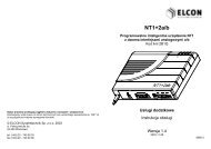
Supply concept<br />
The <strong>ZWR2MSKU</strong> can be either locally powered or operated with remote power<br />
supply (LT2M-side or NT2M-side). If local supply voltage is provided, then the<br />
<strong>ZWR2MSKU</strong> makes use of it even under the condition remote power supply would<br />
be additionally applied. Local feeding always has priority over remote power supply.<br />
LT2MSKU <strong>ZWR2MSKU</strong><br />
local power supply<br />
Fig. 3: <strong>ZWR2MSKU</strong> with local power supply<br />
NT2MSKU-E<br />
or<br />
NT2MSKU-T<br />
The <strong>ZWR2MSKU</strong> is powered by the line terminating unit with 112 VDC (+ 3 VDC) via<br />
the twin wire. It shall be taken into consideration that the remote power supply can be<br />
only effected either from the LT2M side or the NT2M side. Default configuration upon<br />
delivery is LT2M-side remote feeding of the <strong>ZWR2MSKU</strong>.<br />
LT2MSKU <strong>ZWR2MSKU</strong>1<br />
Remote power supply for the LT2M-side<br />
<strong>ZWR2MSKU</strong> 1 via line terminating unit<br />
LT2MSKU<br />
Fig. 4: Two cascaded <strong>ZWR2MSKU</strong> with related remote power supply<br />
2 Assembly and mounting instructions<br />
General<br />
For installing the regenerative repeater please push carefully the <strong>ZWR2MSKU</strong> into<br />
the corresponding slot. The two pilots on the housing are used as reverse polarity<br />
protection. The metal bracket on the front of the repeater can be used for removing<br />
the unit from the slot.<br />
Switch to remote power-feeding from NT2M<br />
<strong>ZWR2MSKU</strong> 2<br />
NT2MSKU-E<br />
or<br />
NT2MSKU-T<br />
Remote power supply for the NT2M-side <strong>ZWR2MSKU</strong> 2 via<br />
network terminating unit NT2MSKU-E or NT2MSKU-T<br />
The <strong>ZWR2MSKU</strong> is default set to remote power feeding from the LT2MSKU unit. For<br />
switching into NT feeding please follow the below named instruction:<br />
ELCON <strong>Systemtechnik</strong> GmbH Page 4 of 8<br />
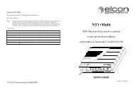
Pilots<br />
Fig. 5:<br />
Connection side of<br />
the <strong>ZWR2MSKU</strong><br />
Attachment screws<br />
Connection cable for<br />
changing of the remote<br />
power supply<br />
In direction of NT<br />
1. Disassembling of the housing – please remove the<br />
four screws (see figure 5) of the housing on the<br />
connection side of the <strong>ZWR2MSKU</strong>.<br />
2. Please remove the housing cap including the<br />
mounted PCB’s from the housing. Please pay<br />
attention, that the sealing rubber will not be loosed<br />
(he is located in the notch between the housing and<br />
the cap).<br />
3. Please remove carefully the power cable connector<br />
from the jack “FSP-LT” (see fig. 6)<br />
4. Please snap the cable connector carefully into the<br />
jack “FSP-NT”.<br />
5. Assembling of the housing – please push the housing<br />
cap including the two PCB’s and the aluminium foil<br />
into the housing. Please pay attention for the<br />
mounting direction – the LED’s must meet the light<br />
conductors in the housing. Furthermore please take<br />
care, that the connection cables will not be jammed.<br />
6. Please close the housing by tighten the 4 screws.<br />
In direction of LT<br />
Sealing rubber<br />
Fig. 6: Change of the remote power supply direction<br />
ELCON <strong>Systemtechnik</strong> GmbH Page 5 of 8
3 Putting into operation<br />
General<br />
After inserting the <strong>ZWR2MSKU</strong> into the corresponding slot the following start-up<br />
procedure is arising.:<br />
(Assumption: the power supply is already connected and the SHDSL transmission<br />
path from the LT and NT is active)<br />
1. The device is beginning with an self-test procedure in the first ca. 15 seconds.<br />
During this time both LED’s will not shine!<br />
2. After this the LT2MSKU is starting up the SHDSL line to the <strong>ZWR2MSKU</strong> (first<br />
transmission path) and the red UKS-LED is blinking with a frequency of 4 Hz.<br />
3. After successful set-up of the first transmission path, the red UKS-LED is<br />
blinking with 1 Hz frequency. During this time the second transmission path<br />
between the <strong>ZWR2MSKU</strong> and the NT2MSKU will be built-up.<br />
4. If the red UKS-LED is switched off finally, than the complete transmission path<br />
is established.<br />
The <strong>ZWR2MSKU</strong> is controlled by the LT2MSKU and can be managed by the <strong>Elcon</strong><br />
Network Management System (ENMS).<br />
Special characteristic during the SHDSL Start-up<br />
Please take into account, that the restart time of an aborted SHDSL line could reach<br />
ca. 1 minute by using one <strong>ZWR2MSKU</strong> and up to 4 minutes by using two repeaters<br />
in the SHDSL transmission path (the given time targets are defined by the ITU-/ ETSI<br />
standards ITU-T G.991.2 and ETSI TS 101 524)<br />
5 Interfaces<br />
Pin assignment of the <strong>ZWR2MSKU</strong><br />
1 2<br />
Pin connector 1:<br />
2, 3 SHDSL connection in LT direction<br />
7 FPE<br />
11, 12 Local supply voltage ranging from<br />
20 VDC ... 75 VDC<br />
11: Negative potential<br />
12: Positive potential<br />
Pin connector 2:<br />
7 FPE<br />
11, 12 SHDSL link in NT direction<br />
ELCON <strong>Systemtechnik</strong> GmbH Page 6 of 8<br />
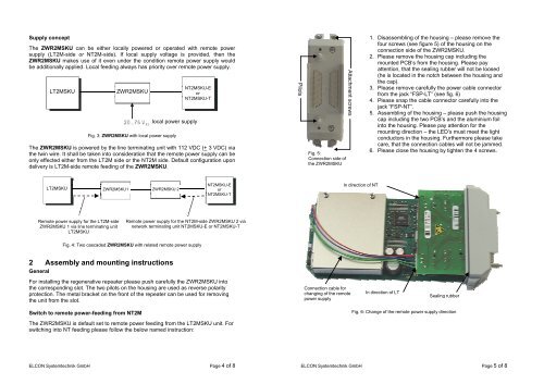
1 Description of regenerative repeater <strong>ZWR2MSKU</strong><br />
General<br />
The regenerative repeater <strong>ZWR2MSKU</strong> is used if the line length between line<br />
terminating unit LT2MSKU and network terminating unit NT2MSKU-E or NT2MSKU-T<br />
exceeds the maximum operating range of the UKS interface.<br />
When using one <strong>ZWR2MSKU</strong> the range is doubled, whereas application of two<br />
cascaded <strong>ZWR2MSKU</strong> allows to quadruple the transmission range of the SHDSL<br />
system.<br />
The regenerative repeater for SHDSL transmission <strong>ZWR2MSKU</strong> with 1 UKS<br />
interface regenerates the attenuated and distorted signal of incoming pulse<br />
sequences and forwards it further. The line digit rate is 2320 kbps.<br />
The repeater is accommodated in an ABS plastic cassette (protected as per IP 52/54),<br />
and can be installed either in a cable fitting or in a repeater rack ZWRE which is<br />
designed for installation into cable junction boxes (KVz).<br />
The <strong>ZWR2MSKU</strong> requires 1 slot in the ZWR subrack or in a cable fitting.<br />
The figures below show the basic structure of an SHDSL system including 1<br />
repeater, respectively, two cascaded repeaters.<br />
1. path (1. DA)<br />
(LT2M-side<br />
LT2MSKU <strong>ZWR2MSKU</strong><br />
1. path (1. DA)<br />
(NT2M-side<br />
NT2MSKU-E<br />
or<br />
NT2MSKU-T<br />
Fig. 1: Structure of a 1DA-SHDSL system with one repeater <strong>ZWR2MSKU</strong><br />
1. path (1.DA)<br />
(LT2M-side)<br />
LT2MSKU <strong>ZWR2MSKU</strong>1<br />
1. path (1.DA)<br />
<strong>ZWR2MSKU</strong> 2<br />
Fig. 2: Structure of a 1DA-SHDSL system<br />
with two cascaded regenerative repeaters<br />
1. path (1.DA)<br />
(NT2M-side)<br />
NT2MSKU-E<br />
or<br />
NT2MSKU-T<br />
ELCON <strong>Systemtechnik</strong> GmbH Page 3 of 8
Contents<br />
1 Description of regenerative repeater <strong>ZWR2MSKU</strong>.............................................. 3<br />
2 Supply concept.................................................................................................... 4<br />
3 Assembly and mounting instructions ................................................................... 4<br />
4 Putting into operation .......................................................................................... 6<br />
5 Interfaces............................................................................................................. 6<br />
6 Indicating elements ............................................................................................. 7<br />
7 Technical data (in extracts) ................................................................................. 7<br />
8 Safety precautions............................................................................................... 8<br />
ELCON <strong>Systemtechnik</strong> GmbH Page 2 of 8<br />
6 Indicating elements<br />
Fig. 6: Front side of the <strong>ZWR2MSKU</strong><br />
Meaning EIN UKS<br />
Remote or local power applied ON<br />
No power supply OFF<br />
First path section is being established 4 Hz<br />
Second path section is being established 1 Hz<br />
Line set-up has been completed OFF<br />
Table 1: Meaning of LED displays<br />
Explanation of symbols:<br />
ON LED shines permanently<br />
OFF LED does not shine<br />
1 Hz LED flashes at 1 Hz<br />
4Hz LED flashes at 4 Hz<br />
7 Technical data (in extracts)<br />
Local power feeding 20 – 75 VDC<br />
Remote power feeding 112 VDC + 3 V<br />
Power consumption by local power < 4W<br />
Feeding range max. 3300 m (at 0.4 mm PE cable)<br />
ELCON <strong>Systemtechnik</strong> GmbH Page 7 of 8
8 Safety precautions<br />
Keep this instruction at a safe place!<br />
Please adhere to the following safety precautions. Read them through carefully<br />
before putting the device into operation.<br />
ESD protection<br />
Upon opening and during installation of components of the HDSL transmission<br />
system, please take the protective measures as per IEC 61340-5-1.<br />
Precautionary measures in case of thunderstorms<br />
Do not work on the SHDSL transmission system and its components during thunderstorms<br />
(Plugging and unplugging of sub-units and cables should be avoided; Do not<br />
connect the SNG2M to the network terminating unit / line terminating unit).<br />
Telecommunication installations with remote power supply<br />
Upon working on the SHDSL transmission system, its components and cables,<br />
please observe the provisions specified in DIN 57800, part 3 (VDE 0800, part 3).<br />
Only qualified staff is allowed to carry out the respective works!<br />
Earthing and potential equalization<br />
During installation, operation and maintenance of the SHDSL transmission system<br />
pay attention to the IEC 60364-5-54. The earth contact of the SNG2M (FPE,<br />
green/yellow conductor) has to be always connected with the network terminating<br />
unit / line terminating unit.<br />
Warning of dangerous electrical voltage<br />
The SHDSL transmission system has interfaces with dangerous electric voltage. All<br />
works on the system shall be carried out only by qualified personnel.<br />
Warning of dangerous laser radiation - laser of class 1<br />
Never look directly or indirectly (e.g. via a mirror) into the laser beam, i.e. to the end<br />
of the fibre cable or the respective connector. To avoid any unintentional look into the<br />
laser beam, open cable ends or connectors shall be principally sealed with a dust<br />
cover.<br />
To maintain the superior transmission properties of optical fibre cable, it must not be<br />
bent. To avoid bending of the glass-fibre cable, it shall be inserted into the provided<br />
take-up unit (→ fig. 58). The radius for reversing shall be no less than 60 mm (e.g.<br />
the smallest admissible bending radius is 30 mm). For this, see also the TS<br />
0011/02.96 (switching cable for telecommunication cable; fibre switching cable of<br />
type SVH with monomode fibre). Further, open cable ends and connectors shall be<br />
provided with a dust cover, to prevent pollution which would lead to additional<br />
attenuation. Therefore do not touch to the fibre end faces. For cleaning of the glassfibre<br />
connectors (if necessary), please use the specially provided cleaning pads and<br />
materials. Do never use compressed air or the air you breathe to blow away any<br />
impurities.<br />
ELCON <strong>Systemtechnik</strong> GmbH Page 8 of 8<br />
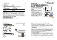
2 Mbps SHDSL regenerative repeater for<br />
1-pair copper-wires<br />
<strong>ZWR2MSKU</strong> <strong>1P</strong><br />
Assembly Instruction<br />
Order-Number: 101 413