Download the rHead⢠RECON Surgical Technique - Small Bone ...
Download the rHead⢠RECON Surgical Technique - Small Bone ...
Download the rHead⢠RECON Surgical Technique - Small Bone ...

You also want an ePaper? Increase the reach of your titles
YUMPU automatically turns print PDFs into web optimized ePapers that Google loves.
S U R G I C A L<br />
T E C H N I Q U E<br />
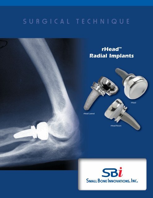
rHead <br />
Radial Implants<br />
rHead<br />
rHead Lateral<br />
rHead Recon
Head Radial Implants<br />
S U R G I C A L T E C H N I Q U E<br />
C O N T E N T S<br />
Introduction 1<br />
Design Rationale 2<br />
Surgeon Preferences 3<br />
Anatomy of <strong>the</strong> Radial Head 4<br />
Disorders of <strong>the</strong> Proximal Radioulnar Joint 5<br />
<strong>Surgical</strong> Procedure<br />
1. The Initial Incision 6<br />
2. Capsular Exposure 7<br />
3. Using <strong>the</strong> Radial Head Resection Guide, Standard Collar 8<br />
3.1. Using <strong>the</strong> Radial Head Resection Guide, 6mm Extended Collar 9<br />
4. Resecting <strong>the</strong> Radial Head 10<br />
5. Intramedullary Preparation 11<br />
6. Trial Stem and Head Insertion 12<br />
7. Implanting <strong>the</strong> Final Components (rHead) 14<br />
7.1. Implanting <strong>the</strong> Final Components (rHead Recon Bi-Polar) 15<br />
7.2. Implanting <strong>the</strong> Final Components (rHead Recon Lateral) 16<br />
8. Closure 18<br />
9. Aftercare 18<br />
Implant Dimensions 19<br />
Indications and Contraindications 19<br />
Warnings, Precautions and<br />
Patient Counseling Information 19
Introduction<br />
The radial head is an important component of both normal elbow<br />
as well as forearm function contributing to <strong>the</strong> radiocapitellar and<br />
proximal radioulnar joints. Stability testing has demonstrated that<br />
<strong>the</strong> radial head is an important “second line” constraint to resist<br />
valgus loads (after <strong>the</strong> medial collateral ligament).<br />
Radial head resection, while occasionally necessary from fracture,<br />
osteochondrosis, or secondary arthritis, is not without adverse<br />
effect on both elbow and forearm function. In-depth laboratory<br />
studies have demonstrated <strong>the</strong> important role of <strong>the</strong> radial head<br />
in elbow kinematics, force distribution, and load transfer across<br />
<strong>the</strong> forearm and elbow joint.<br />
rHead<br />
Radial head resection has been implicated in persistent elbow<br />
instability in elbow fracture-dislocation, rotational instability<br />
injuries, and medial-lateral translation injury. Forearm axial<br />
instability can result from radial head excision if <strong>the</strong> remaining<br />
stabilizers have been compromised (<strong>the</strong> Essex-Lopresti lesion).<br />
The common thread in all of <strong>the</strong> instabilities of <strong>the</strong> forearm and<br />
elbow is one of ligament injury in association with bone loss. Once<br />
<strong>the</strong> secondary stabilizer is removed (i.e. radial head) and elements<br />
of <strong>the</strong> soft tissues (collateral ligaments, interosseous membrane of<br />
<strong>the</strong> forearm and/or distal and proximal radio-ulnar joints) are<br />
compromised, joint instability is noted to increase.<br />
rHead Recon<br />
Replacement of <strong>the</strong> radial head is an anatomic and functional<br />
solution to acute elbow and forearm instability when internal<br />
fixation of <strong>the</strong> radial head fractures cannot be performed. It is also<br />
indicated in instances in which residual symptoms of pain or<br />
instability prompt <strong>the</strong> use of <strong>the</strong> delayed insertion of a radial head<br />
implant as a reconstruction procedure.<br />
rHead Lateral<br />
1
Head Design Rationale<br />
The rHead Standard, Recon, and Lateral styles make up a family of<br />
anatomically designed radial head implants.They are offered in multiple<br />
sizes to duplicate <strong>the</strong> anthropomorphic differences of <strong>the</strong> radial head<br />
and can be used to correct complex elbow instabilities or for elbow<br />
reconstruction. These implants are made up of a head and a stem<br />
component and are modular within each of <strong>the</strong> rHead styles.<br />
The heads are designed with a concave articular surface to articulate<br />
with <strong>the</strong> convexity of <strong>the</strong> capitellum. There are three sizes offered. The<br />
circumference approximates <strong>the</strong> normal proximal radioulnar joint<br />
articulation, preserves <strong>the</strong> annular ligament, and minimizes release of<br />
<strong>the</strong> important lateral collateral ligaments.<br />
The stems are designed with a curve to match <strong>the</strong> anatomical geometry<br />
of <strong>the</strong> proximal radius and to ease insertion into <strong>the</strong> intramedullary<br />
canal. The stems are cement optional. There are four sizes of stems,<br />
each of which are offered with two collar lengths. The extended collared<br />
stems are used with distally migrated fractures or where poor bone<br />
quality makes proper implantation problematic.<br />
A comprehensive instrument set is provided for <strong>the</strong> rHead System<br />
including trials sizers, broaches, and impactors. A radial head<br />
resection guide is also included and is used to establish <strong>the</strong> anatomical<br />
axis of rotation of <strong>the</strong> forearm and <strong>the</strong> proper position of <strong>the</strong><br />
osteotomy. This prevents rotational malalignment that may cause poor<br />
radio-capitellar contact leading to instability and/or cartilage wear.<br />
Note that <strong>the</strong> anatomy of <strong>the</strong> proximal radial head and neck are<br />
offset 15º laterally to <strong>the</strong> shaft of <strong>the</strong> radius with <strong>the</strong> forearm in<br />
supination (SEE FIGURE B, PAGE 4)<br />
The rHead Standard is designed with a Morse taper coupling<br />
mechanism to firmly attach <strong>the</strong> head onto <strong>the</strong> stem.The rHead Standard<br />
was SBi’s first radial head implant developed and has been on <strong>the</strong><br />
market since 1998.<br />
The rHead <strong>RECON</strong> is designed with a “ball/socket” (bipolar)<br />
coupling mechanism between <strong>the</strong> head and stem which adds an<br />
element of alignment flexibility. This facilitates proper radio/capitellar<br />
contact through a functional range of flexion & extension during<br />
forearm rotation. The rotational flexibility allows for <strong>the</strong> adaptation/correction<br />
of alignment variations between <strong>the</strong> radius and<br />
capitellum. This is especially true in reconstructive situations when<br />
proper axial alignment is difficult to attain.<br />
The rHead Lateral is designed using a dovetail coupling mechanism.<br />
This side-loading feature allows for easier insertion of <strong>the</strong> head while it<br />
is being assembled to <strong>the</strong> stem using a specially designed assembly<br />
tool. The rHead Lateral implant is tissue sparing by requiring a less<br />
invasive approach and exposure, minimizing possible ligament<br />
disruption or damage. The dove-tail locking mechanism allows for easy<br />
insertion without <strong>the</strong> use of a set screw.<br />
2 rHead Radial Implants <strong>Surgical</strong> <strong>Technique</strong>
Surgeon Preferences<br />
Recommended clinical situations for potential<br />
use of this device are as follows:<br />
Acute Trauma<br />
1. Comminuted radial head fracture requiring<br />
resection associated with ligament injury<br />
a) Elbow dislocation<br />
b) Distal radioulnar joint injury<br />
(Essex-Lopresti injury)<br />
2. Comminuted radial head fracture requiring<br />
resection with associated fracture(s)<br />
a) Coronoid type II or III fracture (single<br />
or comminuted more than half of <strong>the</strong><br />
coronoid process)<br />
b) Olecranon type III fracture (displaced or<br />
comminuted and unstable)<br />
After radial head excision with evidence of medial<br />
collateral ligament insufficiency.<br />
Reconstruction<br />
Malalignment of <strong>the</strong> resected proximal radius under <strong>the</strong><br />
following circumstances:<br />
1. Instability after radial head resection in <strong>the</strong><br />
context of:<br />
a) Medial collateral deficiency or reconstruction<br />
b) Lateral collateral deficiency or reconstruction<br />
c) Axial (Essex-Lopresti) stabilization<br />
2. Failed prior radial head replacement.<br />
3. With interposition arthroplasty if <strong>the</strong> radial head<br />
is excised and residual elbow instability is<br />
enhanced by replacement.<br />
In general <strong>the</strong> rHead Recon was designed for use in<br />
circumstances in which <strong>the</strong> proximal radius cannot be<br />
anatomically aligned with <strong>the</strong> capitellum.<br />
Clinical situations where <strong>the</strong> use of this<br />
device should be avoided:<br />
Acute Trauma<br />
1. Older patient with a comminuted radial head<br />
fracture requiring radial head excision without<br />
evidence of elbow instability or o<strong>the</strong>r associated<br />
injury (greater than age 65)<br />
2. Open fracture of <strong>the</strong> radial head, olecranon<br />
or associated elbow disolcation with high<br />
risk for sepsis<br />
3. Mason type I or II radial head fractures<br />
4. Mason type II radial head fracture not associated<br />
with elbow or forearm instability.<br />
Reconstruction<br />
1. Severe malalignment of forearm, proximal radius<br />
or ulna (e.g. congenital radial head dislocation or<br />
malunion Monteggia fracture).<br />
2. Lack of proper alignment with trial insertion.<br />
3. Disease or injury of <strong>the</strong> capitellum<br />
(e.g. Osteochondrosis of <strong>the</strong> capitellum).<br />
General<br />
1. Prior sepsis or concern regarding wound<br />
contamination<br />
2. Known allergy to implant constituents<br />
3. Skeletal immaturity<br />
4. <strong>Bone</strong>, tendon or muscle, or adjacent soft tissue<br />
compromised by disease, trauma or prior<br />
implantation which cannot provide adequate<br />
elbow stability or fixation for <strong>the</strong> pros<strong>the</strong>sis.<br />
3
15º<br />
Anatomy of <strong>the</strong> Radial Head<br />
1. The radial head articulates with <strong>the</strong> capitellum and<br />
radial (greater sigmoid) notch of <strong>the</strong> ulna (FIGURE A).<br />
2. The radial head makes a 15° lateral angle to <strong>the</strong> radial<br />
shaft away from <strong>the</strong> tuberosity (FIGURE B).<br />
3. Ligaments about <strong>the</strong> radial head provide important soft<br />
tissue support and are essential to elbow stability after<br />
radial head replacement (FIGURE C).<br />
4. Stress distribution varies in pronation and supination<br />
but averages 60% radiohumeral and 40% at <strong>the</strong><br />
ulnohumeral articulation.<br />
5. Elbow stability is related to articular geometry and<br />
ligament constraint.<br />
FIGURE A<br />
FIGURE B<br />
6. Loss of medial collateral ligament and/or radial<br />
head produces primary or secondary elbow instability.<br />
Radial head replacement aids in restoring elbow<br />
stability (FIGURE D).<br />
7. Recon only: After radial head resection, or following<br />
ulnar fracture, <strong>the</strong> proximal radius may not align with<br />
<strong>the</strong> capitellum.<br />
Radial collateral<br />
ligament<br />
Annular ligament<br />
Lateral ulnar<br />
collateral ligament<br />
FIGURE C<br />
capsule<br />
FIGURE D<br />
4 rHead Radial Implants <strong>Surgical</strong> <strong>Technique</strong>
Disorders of <strong>the</strong> Proximal Radioulnar Joint<br />
The proximal radioulnar and radiocapitellar joint<br />
articulations may be affected by traumatic and acquired<br />
disorders. Traumatic injury is common. Injuries include:<br />
1. Radial head fractures (Mason types I-III) and Mason<br />
Type IV — complex radial head fracture associated<br />
with ligament injuries<br />
2. Combined proximal ulna fracture with radial head<br />
dislocation or fracture (Monteggia lesions I-IV)<br />
3. Radial head fracture associated with dislocation<br />
of <strong>the</strong> elbow (anterior, posterior or lateral)<br />
4. Forearm and elbow injuries (radial head fracture<br />
and interosseous membrane disruption) —<br />
The Essex-Lopresti lesion.<br />
Elbow Instability<br />
All but one of <strong>the</strong>se above conditions relate to elbow<br />
instability and are classified as:<br />
1. Dislocation of <strong>the</strong> elbow with radial head fracture<br />
2. Monteggia variant with olecranon and radial<br />
head fracture<br />
3. Concurrent medial collateral ligament disruption<br />
Essex-Lopresti Injury<br />
Forearm disassociation (Essex-Lopresti injury) requires<br />
careful diagnosis and initial or delayed radial head<br />
stabilization.<br />
The following should be considered:<br />
1. History of axial loading forearm injury<br />
2. Radial head fracture (often comminuted)<br />
3. Tenderness and pain over DRUJ and forearm.<br />
Treatment:<br />
1. Stabilization of <strong>the</strong> radial head<br />
a) Open reduction & internal fixation<br />
b) Radial head pros<strong>the</strong>sis<br />
2. Immobilization of forearm<br />
3. Operative repair of TFCC<br />
4. Repair or late reconstruction of interosseous<br />
membrane.<br />
Radial head replacement is indicated to restore elbow<br />
and forearm stability in <strong>the</strong>se conditions.<br />
4. Fracture of a major portion of <strong>the</strong> coronoid.<br />
Treatment, rHead:<br />
Comminuted radial head fractures Type III<br />
(FIGURE E) associated with medial collateral ligament<br />
injury require stabilization by medial collateral ligament<br />
repair and internal fixation of <strong>the</strong> radial head or radial<br />
head replacement. Excision of comminuted fracture of<br />
<strong>the</strong> radial head requires radial head replacement if elbow<br />
instability is present. Radial head fracture with<br />
dislocation or Type III coronoid fractures also require<br />
treatment based on <strong>the</strong> type of radial head replacement.<br />
Delayed Treatment, Recon Only:<br />
If <strong>the</strong> injury was not successfully treated initially, a<br />
delayed reconstruction of <strong>the</strong> radio-humeral joint is<br />
sometimes required. This is especially true in instances of<br />
residual angular or axial instability.<br />
FIGURE E<br />
Mason Type III<br />
5
Head Radial Implants <strong>Surgical</strong> <strong>Technique</strong><br />
SURGICAL PROCEDURE<br />
1<br />
The Initial Incision<br />
The patient is placed under a general or a regional anes<strong>the</strong>sia.<br />
The extremity is prepped and draped in <strong>the</strong> usual<br />
sterile fashion. A sterile tourniquet is often a good option.<br />
An arm table may be used if <strong>the</strong> patient is in a supine position<br />
or <strong>the</strong> arm may be brought across <strong>the</strong> chest.<br />
A classic Kocher skin incision is made identifying <strong>the</strong><br />
interval between <strong>the</strong> anconeus and <strong>the</strong> extensor carpi<br />
ulnaris (FIGURE 1). The incision extends approximately<br />
6-7cm. The dissection is carried down to <strong>the</strong> joint capsule.<br />
The origin of <strong>the</strong> anconeus can be released subperiosteally<br />
and retracted posteriorly to permit adequate exposure of<br />
<strong>the</strong> capsule.<br />
FIGURE 1<br />
Extensor carpi<br />
radialis longus<br />
Common extensor<br />
tendon<br />
Entensor carpi<br />
radialis breuis<br />
Extensor digitorum<br />
Triceps brachii<br />
Extensor carpi<br />
ulnaris<br />
Flexor carpi<br />
ulnaris<br />
Olecrannon<br />
Anconeus<br />
6 rHead Radial Implants <strong>Surgical</strong> <strong>Technique</strong>
2<br />
Capular Exposure<br />
If <strong>the</strong> elbow is stable, <strong>the</strong> capsule is exposed by<br />
elevating a portion of <strong>the</strong> extensor carpi ulnaris sufficiently<br />
to allow identification of <strong>the</strong> lateral collateral ligament complex<br />
(FIGURE 2A). Alternatively, <strong>the</strong> extensor carpi ulnaris<br />
may be split longitudinally in line with its fibers staying anterior<br />
to <strong>the</strong> attachment of <strong>the</strong> lateral collateral ligament. The<br />
lateral capsule is divided slightly anteriorly to <strong>the</strong> collateral<br />
ligament and <strong>the</strong> annular ligament and capsule are reflected<br />
anteriorly and posteriorly to expose <strong>the</strong> radial head.<br />
A portion of <strong>the</strong> lateral collateral ligament and anterior capsule<br />
can be reflected off <strong>the</strong> lateral epicondyle and anterior<br />
humerus to expose <strong>the</strong> capitellum if necessary. The lateral<br />
ulnohumeral ligament must not be disturbed. If <strong>the</strong> ligament<br />
has been disrupted, <strong>the</strong>n <strong>the</strong> exposure progresses through<br />
<strong>the</strong> site of disruption to expose <strong>the</strong> resected proximal radius.<br />
The common extensor tendon and elbow joint capsule are<br />
retracted as needed to maximize exposure (FIGURE 2B).<br />
FIGURE 2A<br />
Annular ligament<br />
Lateral collateral<br />
ligament<br />
Extensor carpi ulnaris<br />
Anconeus<br />
FIGURE 2B<br />
7
3<br />
Using <strong>the</strong> Radial Head Resection Guide,<br />
Standard Collar<br />
The radial neck cut requires a resection guide (17-0967). The<br />
device is inserted over <strong>the</strong> capitellum with <strong>the</strong> axis of <strong>the</strong><br />
alignment rod oriented over <strong>the</strong> ulnar styloid (FIGURE 3A).<br />
This alignment reflects <strong>the</strong> anatomic axis of forearm rotation.<br />
Test forearm rotation with <strong>the</strong> guide in place to ensure<br />
proper alignment.The proximal flange of <strong>the</strong> guide is placed<br />
against <strong>the</strong> articular surface of <strong>the</strong> capitellum and <strong>the</strong><br />
rotating flange/alignment rod assembly is <strong>the</strong>n guided<br />
proximally or distally to <strong>the</strong> desired length of radial shaft<br />
resection (FIGURE 3B).<br />
Each notch on <strong>the</strong> threaded portion of <strong>the</strong> rod corresponds<br />
to a different head size. The rotating flange placement<br />
direction must be matched to <strong>the</strong> anticipated radial head<br />
implant size and <strong>the</strong> axis of forearm rotation. Once <strong>the</strong><br />
desired length has been established, <strong>the</strong> proximal flange is<br />
secured by tightening <strong>the</strong> locking nut. The guide must be<br />
again aligned to <strong>the</strong> ulnar styloid (<strong>the</strong> axis of forearm<br />
rotation), not <strong>the</strong> radial shaft.<br />
FIGURE 3A<br />
Alignment rod is<br />
aligned to ulnar styloid<br />
FIGURE 3B<br />
Rotating flange/<br />
Alignment rod assembly<br />
size 4 3 2<br />
Notches correspond to<br />
different head sizes<br />
Locking nut<br />
Proximal flange<br />
8 rHead Radial Implants <strong>Surgical</strong> <strong>Technique</strong>
3.1<br />
Using <strong>the</strong> Radial Head Resection Guide,<br />
6mm Extended Collar<br />
During X-Ray templating it may become apparent that<br />
<strong>the</strong> fracture incurred by <strong>the</strong> patient is distally migrated<br />
and <strong>the</strong> standard 2mm rHead stem collar will not<br />
restore adequate neck length. For this specific situation<br />
<strong>the</strong> rHead system is also offered in a 6mm extended<br />
collar. This 6mm extended collar is intended to be used<br />
with distally migrated fractures of <strong>the</strong> proximal radius.<br />
In addition to a complete set of 6mm extended collar<br />
stem trials, a spacer is included for use with <strong>the</strong> rHead<br />
resection guide. This additional spacer is placed over <strong>the</strong><br />
distal tip of <strong>the</strong> resection guide with <strong>the</strong> raised block<br />
facing <strong>the</strong> proximal portion of <strong>the</strong> resection guide. The<br />
spacer is slid proximal until it makes contact with <strong>the</strong><br />
“Rotating flange” (FIGURE 3C). The remainder of <strong>the</strong><br />
technique is unchanged. The addition of this spacer<br />
assures that <strong>the</strong> proper amount of bone is resected for <strong>the</strong><br />
extended collar implant<br />
Rotating Flange<br />
Additional spacer for 6mm<br />
extended stem (17-0929)<br />
FIGURE 3C<br />
9
4<br />
Resecting <strong>the</strong> Radial Head<br />
Using <strong>the</strong> resection guide, <strong>the</strong> blade should be guided by <strong>the</strong><br />
distal surface of <strong>the</strong> rotating flange (FIGURE 4A). During <strong>the</strong><br />
resection, <strong>the</strong> forearm is pronated and supinated while <strong>the</strong><br />
cutting guide is used to align <strong>the</strong> sawblade perpendicular to<br />
<strong>the</strong> axis of rotation (FIGURE 4B). Once initial alignment cuts<br />
have been made, <strong>the</strong> guide is removed and <strong>the</strong> resection is<br />
completed. The distal extent of resection is <strong>the</strong> minimal<br />
amount that is consistent with <strong>the</strong> restoration of function<br />
(FIGURE 4C). This includes at least <strong>the</strong> margin articulating<br />
with <strong>the</strong> ulna at <strong>the</strong> radial notch.<br />
When <strong>the</strong> rHead Recon is to be used, after radial head<br />
resection was previously performed, <strong>the</strong> guide is employed<br />
to “freshen” <strong>the</strong> resected proximal radius. If <strong>the</strong> medullary<br />
canal is not obvious after <strong>the</strong> radius has been recut, a high<br />
speed bone burr is employed to identify <strong>the</strong> proxmial<br />
radial canal.<br />
In addition, radial length should be restored (axial traction)<br />
using a lamina spreader if <strong>the</strong>re is a positive ulnar variance.<br />
FIGURE 4B<br />
FIGURE 4A<br />
Blade is guided by distal<br />
surface of flange<br />
FIGURE 4C<br />
10 rHead Radial Implants <strong>Surgical</strong> <strong>Technique</strong>
5<br />
Intramedullary Preparation<br />
If <strong>the</strong> elbow is unstable, varus stress and rotation of <strong>the</strong><br />
forearm into supination allows improved access to <strong>the</strong><br />
medullary canal. If <strong>the</strong> elbow is stable but <strong>the</strong> exposure is not<br />
adequate to access <strong>the</strong> medullary canal, careful reflection of<br />
<strong>the</strong> origin of <strong>the</strong> collateral ligament from <strong>the</strong> lateral<br />
epicondyle may be necessary to permit subluxation to <strong>the</strong><br />
medullary canal. The canal can be entered with a starter awl<br />
using a twisting motion, <strong>the</strong> tip of a pair of curved needle<br />
holders or a high speed bone burr, so <strong>the</strong> broaching process<br />
can be initiated. The canal is <strong>the</strong>n broached as allowed by<br />
<strong>the</strong> pathologic anatomy of <strong>the</strong> proximal radius (FIGURE 5).<br />
The curve of <strong>the</strong> broach should be directed away from <strong>the</strong><br />
bicipital tuberosity and towards <strong>the</strong> radial styloid (see<br />
FIGURE 6A, page 12). If <strong>the</strong> position of <strong>the</strong> tuberosity cannot<br />
be easily assessed, it generally is opposite of <strong>the</strong> radial<br />
styloid. Serial sized broaches are used until <strong>the</strong> broach fits<br />
snugly in <strong>the</strong> canal at <strong>the</strong> appropriate depth.<br />
FIGURE 5<br />
The curve of <strong>the</strong> broach should<br />
be directed towards <strong>the</strong> radial<br />
styloid.<br />
11
6<br />
Trial Stem and Head Insertion<br />
The appropriate sized trial stem is inserted in an arc-like<br />
fashion, facilitated by <strong>the</strong> curve of <strong>the</strong> stem (FIGURE 6A).<br />
Assure <strong>the</strong> collar is flush with <strong>the</strong> resection.<br />
Choosing <strong>the</strong> Correct Head Size<br />
Use <strong>the</strong> resected native head to properly determine <strong>the</strong><br />
head size to be trialed. To avoid overstuffing, if <strong>the</strong> native<br />
head is between two sizes, it is generally preferable to select<br />
<strong>the</strong> smaller ra<strong>the</strong>r than <strong>the</strong> larger size.<br />
The trial head is attached to <strong>the</strong> trial stem (FIGURE 6B), and<br />
tracking, both in flexion and extension and forearm rotation,<br />
should be carefully assessed. Malalignment of <strong>the</strong> osteotomy<br />
will cause abnormal tracking during flexion/extension and<br />
forearm pronation/supination.<br />
NOTE: In some instances adequate tracking cannot be<br />
attained. In this circumstance <strong>the</strong> implant should not be<br />
used.<br />
FIGURE 6A<br />
rhead Lateral<br />
FIGURE 6B<br />
Trial head<br />
Trial radial stem<br />
12 rHead Radial Implants <strong>Surgical</strong> <strong>Technique</strong>
IMPORTANT: Please Take Note<br />
“Implanting <strong>the</strong> Final Components”<br />
The approach will vary slightly, depending on<br />
<strong>the</strong> rHead Radial Implant that is used---<br />
rHead technique,<br />
rHead Recon technique, or<br />
rHead Lateral technique.<br />
Those variations are outlined in some detail<br />
on <strong>the</strong> next three pages.<br />
13
7<br />
rHead :<br />
Implanting <strong>the</strong> Final Components<br />
Once acceptable alignment has been determined, <strong>the</strong><br />
trials are removed and <strong>the</strong> permanent pros<strong>the</strong>sis is inserted<br />
in two steps. First, using <strong>the</strong> same arc-like motion as<br />
shown in (FIGURE 6A, page 12) <strong>the</strong> radial stem is placed<br />
in <strong>the</strong> medullary canal and tapped into place with <strong>the</strong><br />
impactor (FIGURE 7A). If a firm fixation is not present at<br />
<strong>the</strong> time of <strong>the</strong> insertion of <strong>the</strong> trial stem (i.e. stem can be<br />
easily extracted from or rotated in <strong>the</strong> medullary canal),<br />
<strong>the</strong>n bone cement (PMMA) is recommended. Second, <strong>the</strong><br />
modular head is placed over <strong>the</strong> taper while applying<br />
longitudinal distraction and/or varus stress to distract <strong>the</strong><br />
radiocapitellar interface sufficiently to permit <strong>the</strong> radial<br />
head to be inserted. Once inserted over <strong>the</strong> taper, <strong>the</strong><br />
radial head is secured using <strong>the</strong> impactor (FIGURE 7B).<br />
The elbow is <strong>the</strong>n reduced (FIGURE 7C) and tested again<br />
in flexion/extension and pronation/supination.<br />
If exposure permits, <strong>the</strong> head and stem can be assembled<br />
on <strong>the</strong> “back table”.<br />
NOTE Care should be taken to protect <strong>the</strong> taper<br />
from any damage, including but not limited to scratches<br />
and contact with bone cement.<br />
FIGURE 7A<br />
Reflected elbow capsule<br />
Impactor<br />
FIGURE 7B<br />
FIGURE 7C<br />
14 rHead Radial Implants <strong>Surgical</strong> <strong>Technique</strong>
7.1<br />
rHead Recon (Bi-Polar):<br />
Implanting <strong>the</strong> Final Components<br />
Once acceptable alignment has been determined, <strong>the</strong> trials<br />
are removed and <strong>the</strong> permanent pros<strong>the</strong>sis is inserted in two<br />
steps. First, using <strong>the</strong> same arc-like motion as shown in<br />
(FIGURE 6A page 12), <strong>the</strong> implant stem is placed in <strong>the</strong><br />
medullary canal and tapped into place with <strong>the</strong> impactor<br />
(FIGURE 7A). If a firm fixation is not present at <strong>the</strong> time of <strong>the</strong><br />
insertion of <strong>the</strong> trial stem (i.e. stem can be easily extracted<br />
from or rotated in <strong>the</strong> medullary canal), <strong>the</strong>n bone cement<br />
(PMMA) is recommended. Second, <strong>the</strong> implant head of <strong>the</strong><br />
pros<strong>the</strong>sis is assembled to <strong>the</strong> implant stem. This is<br />
accomplished by carefully placing <strong>the</strong> implant head into <strong>the</strong><br />
jaws of <strong>the</strong> assembly tool and tighten <strong>the</strong> locking nut<br />
(FIGURE 7B).<br />
While applying longitudinal distraction and/or varus stress<br />
to distract <strong>the</strong> radiocapitellar interface, insert <strong>the</strong> implant<br />
head between <strong>the</strong> capitellum and <strong>the</strong> spherical ball of <strong>the</strong><br />
implant stem. Place <strong>the</strong> lever through <strong>the</strong> center of <strong>the</strong><br />
assembly tool and engage <strong>the</strong> collar of <strong>the</strong> stem (FIGURE<br />
7C). Using <strong>the</strong> assembly tool like a plier, snap <strong>the</strong> implant<br />
head onto <strong>the</strong> stem. Carefully remove <strong>the</strong> assembly tool to<br />
avoid damage to <strong>the</strong> implant. The elbow is <strong>the</strong>n reduced<br />
(FIGURE 7D) and tested again in flexion/extension and<br />
pronation/supination.<br />
NOTE: Care should be taken to protect <strong>the</strong> articulating surfaces<br />
between <strong>the</strong> head and stem of any damage, including,<br />
but not limited to, scratches and contact with bone cement.<br />
FIGURE 7A<br />
FIGURE 7B<br />
Assembly Tool<br />
(17-0992)<br />
Lockig Nut<br />
to contain head<br />
in place<br />
Lever added to <strong>the</strong> center<br />
of <strong>the</strong> assebmly tool<br />
FIGURE 7C<br />
FIGURE 7D<br />
Place <strong>the</strong> lever through <strong>the</strong> center of <strong>the</strong> assembly<br />
tool and engage <strong>the</strong> collar of <strong>the</strong> stem<br />
15
7.2<br />
rHead Lateral:<br />
Implanting <strong>the</strong> Final Components<br />
Connect <strong>the</strong> rHead Lateral Stem Impactor (312-0805) to<br />
<strong>the</strong> collar of <strong>the</strong> appropriate size stem to be implanted<br />
(FIGURE 1).<br />
Use <strong>the</strong> Stem Impactor to maneuver <strong>the</strong> stem and<br />
insert it into <strong>the</strong> prepared canal of <strong>the</strong> radius. When <strong>the</strong><br />
stem is inserted correctly into <strong>the</strong> canal, <strong>the</strong> Axis Alignment<br />
Bar on <strong>the</strong> shaft of <strong>the</strong> Impactor should align with <strong>the</strong><br />
patient’s radial styloid (FIGURE 2). The stem should be<br />
inserted in an arc-like fashion, facilitated by <strong>the</strong> curve of<br />
<strong>the</strong> stem (FIGURE 6A page 12). Tap <strong>the</strong> end of <strong>the</strong> rHead<br />
Lateral Stem Impactor until <strong>the</strong> stem is firmly seated in <strong>the</strong><br />
medullary canal. If <strong>the</strong> stem can be easily extracted or<br />
rotated in <strong>the</strong> canal, bone cement, (PMMA), is recommended.<br />
The head and stem components are coupled toge<strong>the</strong>r<br />
using <strong>the</strong> rHead Lateral Assembly Tool (312-0800). Prior to<br />
beginning assembly, all soft tissue must be cleared away<br />
from <strong>the</strong> locking mechanism. Position <strong>the</strong> appropriately<br />
sized radial head implant so that <strong>the</strong> male portion of <strong>the</strong><br />
head locking mechanism is engaged by <strong>the</strong> female portion<br />
of <strong>the</strong> stem locking mechanism (FIGURE 3).<br />
FIGURE 2<br />
FIGURE 1<br />
Lateral Stem Impacter<br />
(312-0805)<br />
FIGURE 3<br />
Lateral Assembly Tool<br />
(312-0800)<br />
16 rHead Radial Implants <strong>Surgical</strong> <strong>Technique</strong>
Place <strong>the</strong> rHead Lateral Assembly Tool around <strong>the</strong><br />
grooved collar of <strong>the</strong> stem and ensure <strong>the</strong> dimple on <strong>the</strong><br />
radial head implant is engaged by <strong>the</strong> pin on <strong>the</strong> advancer<br />
of <strong>the</strong> rHead Lateral Assembly Tool (FIGURE 4). The trigger<br />
on <strong>the</strong> rHead Lateral Assembly Tool is <strong>the</strong>n compressed to<br />
advance <strong>the</strong> radial head implant until it is fully engaged by<br />
<strong>the</strong> stem. The head is fully locked to <strong>the</strong> stem when an<br />
audible “snap” is heard or felt. Visually, <strong>the</strong> head should<br />
be concentric with <strong>the</strong> stem when properly engaged<br />
(FIGURE 4A). The Assembly Tool can now be removed.<br />
If disassembly should be needed, reverse <strong>the</strong> rHead Lateral<br />
Assembly Tool until <strong>the</strong> pin on <strong>the</strong> advancer is aligned with<br />
<strong>the</strong> dimple on <strong>the</strong> opposite side of <strong>the</strong> radial head implant<br />
(FIGURE 5). Compress <strong>the</strong> trigger on <strong>the</strong> rHead Lateral<br />
Assembly Tool until <strong>the</strong> radial head implant disengages<br />
from <strong>the</strong> stem (FIGURE 5A). Note that <strong>the</strong> radial head<br />
implant is intended for one time use. The radial head<br />
implant may not be reused once it is disengaged from<br />
<strong>the</strong> stem. A new radial head implant must be used if <strong>the</strong><br />
original head is disengaged for any reason.<br />
Note: <strong>the</strong> head and stem trial components (not pictured)<br />
are designed to be a “non-locking” lateral assembly<br />
mechanism. These components will be utilized as<br />
explained in step 6.<br />
Assembly<br />
FIGURE 4A<br />
FIGURE 4<br />
Assembly Side<br />
Disassembly<br />
FIGURE 5<br />
FIGURE 5A<br />
Disassembly Side<br />
17
8<br />
Closure<br />
A simple closure is permitted if <strong>the</strong> collateral ligament is<br />
sufficient. If <strong>the</strong> collateral ligament has been disrupted, a<br />
Krakow stitch is used. A No. 5 absorbable suture is placed<br />
distally, crossing <strong>the</strong> site of <strong>the</strong> lateral ulnar collateral<br />
ligament and is <strong>the</strong>n brought proximally.<br />
Both ends of <strong>the</strong> suture are brought through a drill hole<br />
at <strong>the</strong> anatomic origin of <strong>the</strong> lateral collateral ligament<br />
complex and exit posteriorly.<br />
The forearm is placed in full or partial pronation and <strong>the</strong><br />
suture tied (FIGURE 8). The elbow is splinted at 90 degrees<br />
flexion and in neutral to full pronation. If ligamentous<br />
tissue is insufficient, a formal lateral collateral ligament<br />
reconstruction is done.<br />
FIGURE 8<br />
Proximal radius<br />
Extensor carpi ulnaris<br />
Proximal ulna<br />
Capsule closure<br />
(Krakow stitch)<br />
Anconeus<br />
Lateral capsule<br />
Krakow stitch detail<br />
9<br />
Aftercare<br />
Passive flexion and extension is allowed on <strong>the</strong> second day<br />
assuming <strong>the</strong> elbow is considered stable. The goal of radial<br />
head replacement and soft tissue repair is to achieve elbow<br />
stability. Both flexion/extension and pronation/supination<br />
arcs are allowed without restriction. Active motion can<br />
begin by day five.<br />
As with any pros<strong>the</strong>tic replacement, long term aftercare<br />
requires surveillance. If <strong>the</strong> implant is asymptomatic and<br />
tracks well, routine removal is not necessary.<br />
18 rHead Radial Implants <strong>Surgical</strong> <strong>Technique</strong>
I M P L A N T D I M E N S I O N S<br />
I N D I C AT I O N S<br />
The SBi Radial Head implant is intended for replacement of <strong>the</strong> proximal end of <strong>the</strong> radius:<br />
> Primary replacement after complex (comminuted) fracture of <strong>the</strong> radial head<br />
> Symptomatic sequelae after radial resection<br />
> Axial forearm instability<br />
> Failed silicone radial head implant<br />
> Elbow instability associated with radial head fracture or excision of radial head<br />
> Replacement of <strong>the</strong> radial head for degenerative, or post-traumatic disabilities<br />
presenting pain, crepitation and decreased motion at <strong>the</strong> radiohumeral and/or proximal<br />
radio-ulnar joint.<br />
C O N T R A I N D I C AT I O N S<br />
> <strong>Bone</strong> musculature, tendons, or adjacent soft tissue compromised by disease, infection, or<br />
prior implantation which cannot provide adequate support or fixation for <strong>the</strong> pros<strong>the</strong>sis<br />
> Any active or suspected infection in or around <strong>the</strong> joint<br />
> Skeletal immaturity<br />
> Physiologically or psychologically unsuitable patient<br />
> Known sensitivity to materials used in this device<br />
> Possibility for conservative treatment<br />
WA R N I N G S , P R E C A U T I O N S A N D PAT I E N T C O U N S E L I N G I N F O R M AT I O N<br />
Warnings (See also <strong>the</strong> Patient Counseling Information Section)<br />
> Strenuous loading, excessive mobility, and articular instability all may lead to accelerated<br />
wear and eventual failure by loosening, fracture, or dislocation of <strong>the</strong> device. Patients<br />
should be made aware of <strong>the</strong> increased potential for device failure if excessive demands<br />
are made upon it.<br />
> Notification in accordance with <strong>the</strong> California Safe Drinking Water and Toxic Enforcement<br />
Act of 1986 (Proposition 65):This product contains a chemical(s) known to <strong>the</strong> State of<br />
California to cause cancer, and/or birth defects and o<strong>the</strong>r reproductive toxicity.<br />
Precautions<br />
> The implant is provided sterile in an undamaged package. If ei<strong>the</strong>r <strong>the</strong> implant or <strong>the</strong><br />
package appears damaged, expiration date has been exceeded, or if sterility is questioned<br />
for any reason, <strong>the</strong> implant should not be used. Do not resterilize.<br />
> Meticulous preparation of <strong>the</strong> implant site and selection of <strong>the</strong> proper size implant<br />
increases <strong>the</strong> potential for a successful outcome.<br />
> The implant should be removed from its sterile package only after <strong>the</strong> implant site has<br />
been prepared and properly sized.<br />
> Implants should be handled with blunt instruments to avoid scratching, cutting or nicking<br />
<strong>the</strong> device so as not to adversely affect <strong>the</strong> implant performance. Polished bearing<br />
and articulating surfaces must not come in contact with hard or abrasive surfaces.<br />
> The head and stem should not be implanted if <strong>the</strong> ball and socket features are possibly<br />
damaged, this includes repeated attaching and detaching.<br />
> The head of <strong>the</strong> pros<strong>the</strong>sis is assembled on to <strong>the</strong> head of <strong>the</strong> stem. Prior to assembly<br />
confirm that <strong>the</strong> ball and socket features are dry and free from contaminant.<br />
Patient Counseling Information (See also Warnings)<br />
In addition to <strong>the</strong> patient related information contained in <strong>the</strong> Warnings and Adverse<br />
Events sections, <strong>the</strong> following information should be conveyed to <strong>the</strong> patient.<br />
> While <strong>the</strong> expected life of total joint replacement components is difficult to estimate, it is<br />
finite.These components are made of foreign materials which are placed within <strong>the</strong><br />
body for <strong>the</strong> potential restoration of mobility or reduction of pain. However, due to <strong>the</strong><br />
many biological, mechanical and physiochemical factors which affect <strong>the</strong>se devices, <strong>the</strong><br />
components cannot be expected to withstand <strong>the</strong> activity level and loads of normal<br />
healthy bone for an unlimited period of time.<br />
> Adverse effects may necessitate reoperation, revision, or fusion of <strong>the</strong> involved joint.<br />
Please refer to implant package insert for additional product information including<br />
precautions and warnings.<br />
<strong>Surgical</strong> Videos<br />
For a surgical video DVD of this product contact <strong>Small</strong> <strong>Bone</strong> Innovations, Inc.<br />
or visit our website at www.totalsmallbone.com<br />
Proper surgical procedures and techniques are necessarily <strong>the</strong> responsibility of <strong>the</strong> medical professional. Each surgeon must evaluate <strong>the</strong> appropriateness of <strong>the</strong> surgical technique used based on<br />
personal medical training and experience.<br />
The contents of this document are protected from unauthorized reproduction or duplication under U.S. federal law. Permission to reproduce this document (for educational/instructional use only)<br />
may be obtained by contacting <strong>Small</strong> <strong>Bone</strong> Innovations, Inc.<br />
19
<strong>Small</strong> <strong>Bone</strong> Innovations, Inc.<br />
SBi Customer Service: (800) 778-8837<br />
1380 South Pennsylvania Ave.<br />
Morrisville, PA 19067<br />
Fax (866) SBi-0002<br />
Technical Support: (866) SBi-TIPS<br />
<strong>Small</strong> <strong>Bone</strong> Innovations International<br />
ZA Les Bruyères - BP 28<br />
01960 Péronnas, France<br />
Tel: +33 (0) 474 21 58 19<br />
Fax: +33 (0) 474 21 43 12<br />
info@sbi-intl.com<br />
www.totalsmallbone.com<br />
CAUTION: Federal (United States) law restricts this device to sale by or on <strong>the</strong> order of a physician.<br />
rHead is a trademark of <strong>Small</strong> <strong>Bone</strong> Innovations, Inc.<br />
1005 Copyright ©2010 <strong>Small</strong> <strong>Bone</strong> Innovations, Inc. All rights reserved.<br />
MKT 10414 Rev. A