SCS⢠Volar Distal Radius Plate System - Small Bone Innovations
SCS⢠Volar Distal Radius Plate System - Small Bone Innovations
SCS⢠Volar Distal Radius Plate System - Small Bone Innovations

You also want an ePaper? Increase the reach of your titles
YUMPU automatically turns print PDFs into web optimized ePapers that Google loves.
SURGICAL<br />
TECHNIQUE<br />
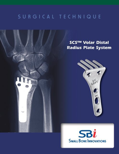
SCS <strong>Volar</strong> <strong>Distal</strong><br />
<strong>Radius</strong> <strong>Plate</strong> <strong>System</strong>
SCS <strong>Volar</strong> <strong>Distal</strong> <strong>Radius</strong> <strong>Plate</strong> <strong>System</strong><br />
SURGICAL TECHNIQUE<br />
CONTENTS<br />
Introduction 1<br />
Preoperative Planning 2<br />
<strong>System</strong> Components 2<br />
Surgical Procedure: Acute Fracture<br />
1. Implant Sizing 3<br />
2. Fracture Reduction 3<br />
3. Incision 4<br />
4. Exposing the <strong>Distal</strong> <strong>Radius</strong> 4<br />
5. Drill Guide Placement 5<br />
6. Drilling The Tine Holes 6<br />
7. <strong>Plate</strong> Insertion 6<br />
8. Final Reduction 7<br />
9. Closure 7<br />
10. Rehabilitation 7<br />
Ordering Information 8<br />
Indications and Contraindications 9
Introduction<br />
The SCS (subchondral support) <strong>Volar</strong> <strong>Distal</strong> <strong>Radius</strong> <strong>Plate</strong> is<br />
designed to internally fix the unstable distal radius with sufficient<br />
stability to allow immediate rehabilitation.<br />
The treatment of displaced distal radius fractures remains<br />
problematic. Malunion, stiffness, and late arthritis are not uncommonly<br />
associated with casting or external fixation.<br />
As for all other juxta-articular and intra-articular fractures, optimal<br />
treatment includes anatomic reduction and internal fixation<br />
that is strong enough to allow immediate rehabilitation of all<br />
joints. 1 However, in the distal radius metaphysis, screw purchase is<br />
often not possible due to fracture geometry and/or osteopenia.<br />
The SCS <strong>Volar</strong> <strong>Distal</strong> <strong>Radius</strong> <strong>Plate</strong> is designed to address these<br />
challenges. Using the biomechanical principle of a bladed plate,<br />
the patented tines of the 3-dimensional SCS <strong>Volar</strong> <strong>Distal</strong> <strong>Radius</strong><br />
<strong>Plate</strong> engage the distal fragments and carry load directly to the<br />
diaphysis.This avoids reliance on weak distal metaphyseal screws<br />
while providing the stability required for immediate postoperative<br />
motion. The SCS <strong>Volar</strong> <strong>Distal</strong> <strong>Radius</strong> <strong>Plate</strong> was found to be<br />
significantly stronger than the typical T-plate in resisting axial<br />
load in cadaveric testing. 2,3<br />
The majority of distal radius fractures in adults can be satisfactorily<br />
treated by simple methods, such as casting or percutaneous<br />
pinning. More complex fractures could be considered for open<br />
reduction and internal fixation with the SCS <strong>Volar</strong> <strong>Distal</strong> <strong>Radius</strong><br />
<strong>Plate</strong>.<br />
The SCS <strong>Volar</strong> <strong>Distal</strong> <strong>Radius</strong> <strong>Plate</strong> is designed with an established<br />
12 o volar tilt to insure proper realignment of the distal<br />
radius after fixation is obtained. The anatomically shaped plate,<br />
with countersinking for the screws, assures a low profile. Right or<br />
left, small and large configurations address the anatomic spectrum.<br />
Constructed of clinically proven stainless steel, the tines<br />
independently support the scaphoid and lunate fossae.<br />
After anatomic reduction, specifically designed templates facilitate<br />
accurate placement of pilot holes for the tines of the SCS<br />
<strong>Volar</strong> <strong>Distal</strong> <strong>Radius</strong> <strong>Plate</strong>.<br />
The SCS <strong>Volar</strong> <strong>Distal</strong> <strong>Radius</strong> <strong>Plate</strong> is useful for the management<br />
of some unstable fractures, impending malunions, non-unions,<br />
and osteotomies of the distal radius. By achieving stable internal<br />
fixation and starting early rehabilitation, the cost and disability of<br />
patient care can be reduced.<br />
1
Preoperative Planning<br />
The surgeon must develop a clear understanding of the exact<br />
three-dimensional fracture geometry prior to surgery. After the<br />
routine initial presentation x-rays (AP, lateral and oblique), additional<br />
studies may be useful. Traction or closed reduction x-rays<br />
may help define intra-articular extension. Distraction PA and lateral<br />
views may reveal associated carpal injuries. 4 In some cases, a<br />
computerized tomograph or magnetic resonance image may help<br />
define the radiocarpal and distal radial ulnar joint (DRUJ) surface<br />
anatomy.<br />
The SCS <strong>Volar</strong> <strong>Distal</strong> <strong>Radius</strong> <strong>Plate</strong> x-ray templates will help estimate<br />
the appropriate plate size and optimal plate position. For<br />
malunions or non-reducible fractures, comparison views of the<br />
unaffected side are helpful.<br />
Occasionally, patients will present with substantial injury edema,<br />
with or without median nerve irritation. These patients must be<br />
carefully evaluated for acute carpal tunnel syndrome (CTS).<br />
Compartment pressure evaluation and emergent EMG/NCV testing<br />
can be of some benefit.<br />
Principles of Treatment<br />
> Anatomic reduction must be achieved<br />
before attempting fixation.<br />
> Intraoperative external distraction<br />
is essential.<br />
> <strong>Bone</strong> graft or bone graft substitute<br />
should be used to fill metaphyseal<br />
defects.<br />
> Place stable internal fixation after<br />
successful reduction.<br />
> Evaluate and treat associated injuries.<br />
> Start early motion of all joints.<br />
Open carpal tunnel release (CTR) is indicated for the emergent<br />
treatment of acute CTS. The much more common problem of<br />
milder, median nerve irritation usually responds well to a stable<br />
reduction of the distal radius with resumption of wrist and finger<br />
motion.<br />
<strong>System</strong> Components<br />
The SCS <strong>Volar</strong> <strong>Distal</strong> <strong>Radius</strong> Plating <strong>System</strong> is designed using<br />
SBI’s <strong>System</strong> Pack Technology. Each of the four choices of<br />
implants comes in its own self-contained disposable instrument<br />
package. The package contains the plate, screw driver / depth<br />
gauge, required screws, K-wires, drill pin,<br />
drill pegs and drill guide. The <strong>System</strong><br />
Pack is sold at a single cost, reducing<br />
the costly efforts expended in tracking<br />
individual screw and K-wire use. The<br />
chances of infection are also reduced<br />
due to the absence of a need to sterilize<br />
a previously used instrument set before<br />
surgery. Not only does this reduce the<br />
chances of infection, it also reduces OR<br />
cycle time and overall costs.<br />
2 SCS <strong>Volar</strong> <strong>Distal</strong> <strong>Radius</strong> <strong>Plate</strong> <strong>System</strong> Surgical Technique
SCS <strong>Volar</strong> <strong>Distal</strong> <strong>Radius</strong> <strong>Plate</strong> <strong>System</strong><br />
TM<br />
1<br />
SURGICAL PROCEDURE: ACUTE FRACTURE<br />
Implant Sizing<br />
The SCS <strong>Volar</strong> <strong>Distal</strong> <strong>Radius</strong> <strong>Plate</strong> is provided in four configurations;<br />
large and small sizes for left and right orientations.<br />
Templates (attached to the outer package) are provided<br />
for use with AP and lateral x-rays for assessment of<br />
proper plate size (FIGURE 1).<br />
FIGURE 1<br />
2<br />
Fracture Reduction<br />
Anatomic reduction is desirable, but not always achievable<br />
before attempting fixation with the SCS <strong>Volar</strong> <strong>Distal</strong><br />
<strong>Radius</strong> <strong>Plate</strong>. External distraction is often a useful tool to<br />
help obtain and maintain reduction before and during<br />
plate application. Options for intra-operative external distraction<br />
include:<br />
a. Sterile finger trap traction pulling in a volar<br />
direction (FIGURE 2A), or;<br />
b. A 2 or 4 pin adjustable external skeletal<br />
fixator (FIGURE 2B)<br />
Reduction without External Skeletal Fixation<br />
After fracture exposure, when the volar cortex is noncomminuted,<br />
manual anatomic reduction can usually be<br />
accomplished by engaging the teeth of the volar fracture<br />
line and then volar flexing the distal fragment to a limit<br />
allowed by the dorsal periosteum. Occasionally, a freer<br />
elevator must be inserted between the cortices to lever<br />
the fracture into reduction. Reduction can be maintained<br />
by placing a rolled towel under the hand and wrist or by<br />
insertion of a .062” trans-styloid K-wire. In cases where<br />
there is comminution of the volar cortex and/or articular<br />
fractures, eternal distraction will usually be required to<br />
maintain reduction until the plate is in place.<br />
Reduction with External Skeletal Fixation<br />
Using the limited open technique, place an appropriate<br />
size half pin across both cortices of the radial diaphysis<br />
about 8-10 cm proximal to the radiocarpal joint. The distractor<br />
half pin should be placed proximal to the intended<br />
proximal screw hole for the plate. The pin is inserted after<br />
pre-drilling and protecting the superficial radial nerve.<br />
Similarly place the second half pin through the base of the<br />
second metacarpal and into the base of the third. Apply<br />
the device, perform an initial closed reduction, and distract.<br />
To facilitate difficult fracture reductions, the external<br />
distractor can be repeatedly adjusted intraoperatively to<br />
change wrist position while maintaining distraction.While<br />
maintaining distraction, radiographic evaluation of carpal<br />
alignment may demonstrate an associated intra-carpal<br />
ligament injury or carpal fracture. K-wires (.045”) may be<br />
used for provisional fixation between fragments to facilitate<br />
plate application.<br />
FIGURE 2A<br />
FIGURE 2B<br />
3
3<br />
Incision<br />
The surgical exposure utilizes a radial volar incision<br />
through the flexor carpi radialis tendon sheath (FIGURE<br />
3A). The distal end of the incision curves toward the radial<br />
styloid and may be further extended by zig zag back<br />
toward the ulnar side (FIGURE 3B). The incision passes<br />
through the superficial and deep layers of the FCR sheath.<br />
The FCR and FPL tendons are retracted ulnarly and the<br />
radial artery radially. Some of the muscle fibers of the FPL<br />
origin will need to be reflected from the radius for proximal<br />
exposure. A palmar branch of the radial artery at the<br />
level of the wrist crease may need ligation.<br />
FIGURE 3A<br />
FIGURE 3B<br />
4<br />
Exposing the <strong>Distal</strong> <strong>Radius</strong><br />
The pronator quadratus is reflected ulnarly from its radial<br />
insertion exposing the entire distal radius ulnarly to the<br />
distal radioulnar joint (FIGURE 4). Care should be taken to<br />
sharply reflect the distal border of the pronator to facilitate<br />
insertion of the drill guide. Partial release of the<br />
fibroosseous sheath of the FCR will also facilitate exposure<br />
of the ulnar side of the distal fragment. Occasionally,<br />
access to the ulnar most drill hole of the plate has to be<br />
between the flexor carpi radialis and the median nerve, in<br />
which case the median palmer cutaneous branch must be<br />
identified.<br />
FIGURE 4<br />
4 SCS <strong>Volar</strong> <strong>Distal</strong> <strong>Radius</strong> <strong>Plate</strong> <strong>System</strong> Surgical Technique
5<br />
Drill Guide Placement<br />
If anatomic reduction is obtained, the drill guide will conform<br />
to the volar surface of the distal radius. If complete<br />
reduction is not obtained, insertion of the K-wires (and<br />
subsequently, the tines) parallel to the articular surface will<br />
allow final reduction to be achieved with the plate. This<br />
means that the shaft of the drill guide (plate) will be at an<br />
angle with the shaft of the radius equal to the required<br />
angle of final correction. There are two radiographic markers<br />
embedded in the stem of the drill guide. These markers<br />
can be viewed fluoroscopically and assist in axial alignment<br />
along the diaphysis of the radius.<br />
FIGURE 5A<br />
A K-wire or needle can be manually inserted into the radiocarpal<br />
joint to identify the distal end of the radius. The<br />
Trial/Drill Guide should be placed on the radius such that<br />
the tine holes (larger holes) will be 1-3 mm proximal to the<br />
subcondral bone of the distal radius and parallel to the<br />
articular surface in the frontal (AP) and saggital (lateral)<br />
planes (FIGURE 5A). The two k-wires from the <strong>System</strong><br />
Pack are inserted through the center k-wire holes in the<br />
Drill Guide into the distal radius (FIGURE 5B). Fluoroscopy<br />
is then used to examine the position of the k-wires relative<br />
to the radiocarpal joint. Fluoroscopic views are taken in<br />
the AP and lateral planes. The x-ray beam should be parallel<br />
to the tine holes in the AP and both pins should be<br />
superimposed on the lateral view. This will give an accurate<br />
determination of tine placement with respect to the<br />
articular surface (FIGURE 5C). The Drill Guide is designed<br />
to insure that the SCS <strong>Volar</strong> <strong>Distal</strong> <strong>Radius</strong> <strong>Plate</strong> tines will<br />
be parallel with the k-wires. Therefore, examining the k-<br />
wire position provides an exact indication of the subsequent<br />
tine placement. The k-wires should be approximately<br />
1-3 mm proximal to the joint and it is acceptable if they,<br />
or the tines, pass through any fracture lines. However, they<br />
should not penetrate the radiocarpal joint. If placement of<br />
the Guide needs to be altered, it can be moved 2 mm proximally<br />
or 2 mm distally by reinserting it over the additional<br />
k-wire holes in the Guide. Note: It will be easier to reinsert<br />
the Guide over the two k-wires if one is cut to a shorter<br />
length so that the Guide can be placed over each k-wire<br />
separately.<br />
FIGURE 5B<br />
FIGURE 5C<br />
X-RAY<br />
22 º<br />
FLUOROSCOPY PLATE<br />
5
6<br />
Drilling the Tine Holes<br />
With Drill Guide placement verified using fluoroscopy, the<br />
tine holes can now be drilled. Using the Drill Pin supplied<br />
in the <strong>System</strong> Pack. The first tine hole is drilled (FIGURE<br />
6A). A Drill Peg from the <strong>System</strong> Pack is then inserted<br />
into the initial tine hole to stabilize the Drill Guide for<br />
additional tine hole drilling (FIGURE 6B). A second tine<br />
hole is drilled using the Drill Pin followed by inserting the<br />
second Drill Peg. The Drill Guide is now fully stabilized<br />
and the remaining tine holes can be drilled.<br />
FIGURE 6A<br />
FIGURE 6B<br />
7<br />
<strong>Plate</strong> Insertion<br />
The Trial/Drill Guide and K-wires are now removed and<br />
the SCS <strong>Volar</strong> <strong>Plate</strong> is placed on the radius by manually<br />
inserting the plate tines into the drilled tine holes (FIG-<br />
URE 7). The plate is designed so that a moderate pressure<br />
will be required to push the square tines into the round<br />
drill holes. During this process manual counterpressure<br />
should be applied to the dorsum of the distal fragment.<br />
FIGURE 7<br />
With the tines situated parallel to the articular surface in<br />
both the frontal (AP) and sagittal (lateral) planes, the shaft<br />
of the plate is applied to the shaft of the radius and held<br />
manually or with a bone clamp. This maneuver produces<br />
the final anatomic reduction.<br />
6 SCS <strong>Volar</strong> <strong>Distal</strong> <strong>Radius</strong> <strong>Plate</strong> <strong>System</strong> Surgical Technique
8<br />
Drilling of the Proximal Screw Holes<br />
With the plate flush on the palmar surface of the radius<br />
shaft, the plate itself is used as a guide for drilling the<br />
screw holes. Again using the <strong>System</strong> Pack Drill Pin, 2 or<br />
3 cortical screw holes are drilled into the radius using the<br />
holes along the shaft of the SCS <strong>Volar</strong> <strong>Distal</strong> <strong>Radius</strong> <strong>Plate</strong><br />
as a guide. The two cancellous screws in the distal end of<br />
the plate are usually not required because the resolution<br />
of forces pushes the distal fragment volarly.<br />
Using the <strong>System</strong> Pack Screwdriver/Depth Gauge, the<br />
required screw lengths are measured (FIGURE 8A) and<br />
the appropriate screws inserted through the plate (FIG-<br />
URE 8B).<br />
FIGURE 8A<br />
Following radius fixation, the DRUJ should be checked for<br />
rotation and translational stability. Occasionally, repair of<br />
the TFC or fixation of the ulnar styloid will be required.<br />
FIGURE 8B<br />
9<br />
Closure<br />
Insofar as possible, the pronator quadratus is closed over<br />
the plate and sutured to its original insertion on the<br />
radius margin of the distal radius (FIGURE 9). Soft tissue<br />
and skin closure follows.<br />
10<br />
Rehabilitation<br />
Postoperative splint or cast support is utilized as required<br />
based on estimation of patient compliance, stability of<br />
the fixation, and nature of soft tissue or skeletal injury of<br />
the distal radioulnar joint. Active finger motion is begun<br />
immediately. Intermittent protected active wrist motion<br />
may be started in approximately 10 days depending on<br />
fracture fixation. In general, the patient is told to lift nothing<br />
heavier than a china dinner plate for the first month.<br />
The progressive activity is allowed based on radiographic<br />
evidence of fracture healing. Generally, 3-4 months are<br />
required for disappearance of the fracture lines.<br />
Radiographic evaluation is recommended at 10 days, 4<br />
weeks, 8 weeks, and 3 months postoperatively.<br />
FIGURE 9<br />
7
SCS <strong>Volar</strong> <strong>Distal</strong> <strong>Radius</strong> <strong>Plate</strong> <strong>System</strong><br />
Ordering Information<br />
Cat No. Description Length Thickness Width at distal end<br />
SCS-LSSP SCS/V <strong>Volar</strong> <strong>Distal</strong> <strong>Radius</strong> <strong>Plate</strong>, Left, <strong>Small</strong> 51mm 1.65mm 22mm<br />
SCS-LLSP SCS/V <strong>Volar</strong> <strong>Distal</strong> <strong>Radius</strong> <strong>Plate</strong>, Left, Large 51mm 1.65mm 27mm<br />
SCS-RSSP SCS/V <strong>Volar</strong> <strong>Distal</strong> <strong>Radius</strong> <strong>Plate</strong>, Right, <strong>Small</strong> 51mm 1.65mm 22mm<br />
SCS-RLSP SCS/V <strong>Volar</strong> <strong>Distal</strong> <strong>Radius</strong> <strong>Plate</strong>, Right, Large 51mm 1.65mm 27mm<br />
Each <strong>System</strong> Pack Contains:<br />
1 plate as described above<br />
3 cortical screws, 3.5mm x 12mm<br />
3 cortical screws, 3.5mm x 14mm<br />
3 cortical screws, 3.5mm x 16mm<br />
3 cortical screws, 3.5mm x 18mm<br />
1 cancellous screw, 4.0mm x 18mm<br />
1 cancellous screw, 4.0mm x 20mm<br />
1 cancellous screw, 4.0mm x 22mm<br />
1 cancellous screw, 4.0mm x 24mm<br />
1 combination screw driver and depth gauge (screw driver is 2.5mm hex)<br />
2 K-wires, .035” diameter (used with trial template for fluoroscopy)<br />
1 Drill Pin, .098” (2.5mm) diameter (to be used with trial template for drilling tine holes)<br />
2 Drill Pegs, .098” (2.5mm) diameter (used to stabilize the trial template during drilling)<br />
1 Trial Template/Drill Guide (specific to the implant configuration as described above)<br />
X-ray template<br />
Ancillary Equipment:<br />
2.5mm drill bit for both cortical and cancellous screws (the drill pin provided in <strong>System</strong> Pack suffices)<br />
Implant Dimensions:<br />
It is difficult to detail this plate since it is anatomically designed in three dimensions. The dimensions stated above are to generally<br />
describe the plates for ordering purposes. An x-ray template is provided with each <strong>System</strong> Pack so the proper size can be<br />
determined pre-operatively.<br />
8 SCS <strong>Volar</strong> <strong>Distal</strong> <strong>Radius</strong> <strong>Plate</strong> <strong>System</strong> Surgical Technique
INDICATIONS<br />
> Comminuted extra-articular distal radius fractures*<br />
> Comminuted dorsal marginal articular distal radius<br />
fractures*<br />
> Comminuted combined intra-articular, extra-articular<br />
distal radius fractures*,**<br />
> Failed original fracture fixation**<br />
> Osteotomy and repair of distal radius malunion**<br />
CONTRAINDICATIONS<br />
> <strong>Bone</strong>, musculature, tendons, or adjacent soft tissue<br />
comprised by disease, infection, or prior implantation<br />
which cannot provide adequate support or fixation for<br />
the prosthesis.<br />
> Any active or suspected infection in or around the<br />
thumb joint.<br />
> Skeletal immaturity.<br />
* Which cannot be satisfactorily stabilized by cast methodology<br />
** Denotes need to consider the addition of bone graft, bone substitute and or supplemental fixation.<br />
The SCS <strong>Volar</strong> <strong>Distal</strong> <strong>Radius</strong> <strong>Plate</strong> <strong>System</strong> was designed under exclusive license from the University of Minnesota, Department of Orthopaedics, and in conjunction with<br />
Matthew D. Putnam, MD and David Gesensway, MD.<br />
Proper surgical procedures and techniques are necessarily the responsibility of the medical professional. Each surgeon must evaluate the appropriateness of the surgical<br />
technique used based on personal medical training and experience.<br />
The contents of this document are protected from unauthorized reproduction or duplication under U.S. federal law. Permission to reproduce this document (for<br />
educational/instructional use only) may be obtained by contacting SBI.<br />
Prescription Information<br />
The SCS (Sub-Chondral Support) <strong>Volar</strong> <strong>Distal</strong> <strong>Radius</strong> <strong>Plate</strong> <strong>System</strong> is intended for internal fixation of the fractured distal radius.<br />
The SCS <strong>Volar</strong> <strong>Distal</strong> <strong>Radius</strong> <strong>Plate</strong> <strong>System</strong> is comprised of a <strong>Distal</strong> <strong>Radius</strong> <strong>Plate</strong>, a drill guide, cortical and cancellous screws and instruments necessary for plate fixation. To assure proper implantation of the<br />
device, the use of the drill guide is required. The SCS <strong>Volar</strong> <strong>Distal</strong> <strong>Radius</strong> <strong>Plate</strong> and screws are single use only and should not be reused. The SCS <strong>Volar</strong> <strong>Distal</strong> <strong>Radius</strong> <strong>Plate</strong> is not designed as a permanent<br />
implant.<br />
Caution<br />
U.S. Federal law restricts this device to sale by or on the order of a physician.<br />
References<br />
1. Putnam MD, Seitz WH Jr. Advances in Fracture Management in the Hand and <strong>Distal</strong> <strong>Radius</strong>. Hand Clinics,<br />
Vol. 5, No. 3, August 1989.<br />
2. Gesensway D, Putnam MD, Mente PL, and Lewis JL. Design and Biomechanics of a <strong>Plate</strong> for the <strong>Distal</strong> <strong>Radius</strong>. Journal of Hand Surgery, 20A: 1021-7, 1995.<br />
3. Gesensway D, Putnam MD, Nelson EW, Mente PL, and Lewis JL. Biomechanics of Dorsal Plating of the <strong>Distal</strong> <strong>Radius</strong>. In: Vastamaki M, ed. 6th Congress of the International Federation of Societies for Surgery of<br />
the Hand (IFSSH). Helsinki, Finland: Monduzzi Editore, 1995: 153-156.<br />
4. Green DP. Carpal Dislocations and Instabilities. In: Green DP, ed. Operative Hand Surgery, 3rd ed. NY:<br />
Churchill Livingstone, 1993: 875.<br />
5. Weil C and Ruby LK. The Dorsal Approach to the Wrist Revisited. Journal Hand Surgery, 13A: 911-12, 1986.<br />
6. Dellon AL. Partial Dorsal Wrist Denervation: Resection of the <strong>Distal</strong> Posterior Interosseus Nerve. Journal of Hand Surgery, 10A: 527-33, 1985.<br />
7. Seitz WH Jr., Putnam MD, and Dick HM. Limited Open Surgical Approach for External Fixation of <strong>Distal</strong> <strong>Radius</strong> Fractures. Journal of Hand Surgery, 15A: 288-293, 1990.<br />
9
<strong>Small</strong> <strong>Bone</strong> <strong>Innovations</strong>, Inc.<br />
1711 South Pennsylvania Ave.<br />
Morrisville, PA 19067<br />
Customer Service (800) 778-8837<br />
Technical Support (866) SBi-TIPS<br />
Fax (215) 428-1795<br />
www.totalsmallbone.com<br />
SBi International, SAS<br />
ZA les Bruyeres<br />
BP 28<br />
01960 Peronnas<br />
France<br />
Tel +33 474 21 58 19<br />
Fax +33 474 21 43 12<br />
info@sbi-intl.com<br />
MKT-30220 Rev. a<br />
Copyright 2006, <strong>Small</strong> <strong>Bone</strong> <strong>Innovations</strong>, Inc.