uHead Ulnar Implant System - Small Bone Innovations
uHead Ulnar Implant System - Small Bone Innovations
uHead Ulnar Implant System - Small Bone Innovations

You also want an ePaper? Increase the reach of your titles
YUMPU automatically turns print PDFs into web optimized ePapers that Google loves.
SURGICAL<br />
TECHNIQUE<br />
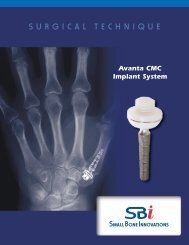
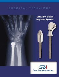
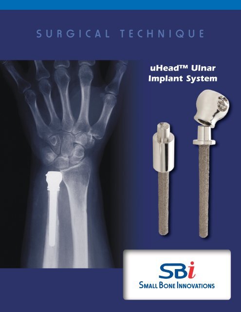
<strong>uHead</strong> <strong>Ulnar</strong><br />
<strong>Implant</strong> <strong>System</strong>
<strong>uHead</strong> <strong>Ulnar</strong> <strong>Implant</strong> <strong>System</strong><br />
SURGICAL TECHNIQUE<br />
CONTENTS<br />
Introduction 1<br />
Disorders of the Radioulnar Joint 2<br />
Design Rationale 3<br />
Sugical Procedure<br />
1. The Initial Incision, Ulna Approach 4<br />
Dorsal Approach Alternative 4<br />
2. Incision of the Extensor Retinaculum 4<br />
3. <strong>Ulnar</strong> Exposure of the Distal Ulna 4<br />
4. Determining Resection Length 5<br />
5. Resection of the Distal Ulna 5<br />
6. Canal Preparation 6<br />
7. Insertion of the Trial Stem 6<br />
8. Trial Head Insertion and Trial Reduction 6<br />
9. <strong>Implant</strong>ing the <strong>Ulnar</strong> Stem Component 6<br />
10. Securing the <strong>Ulnar</strong> Head 7<br />
11. <strong>Ulnar</strong> Head Impaction 7<br />
12. Capsular Closure 8<br />
13. Extensor Retinaculum Closure 8<br />
14. Rehabilitation 8<br />
Indications and Contraindications 9<br />
Patient Counseling Information 9
Introduction<br />
Ligament disruption, ulnar styloid fractures, and fractures<br />
into the distal radioulnar joint are common occurrences<br />
following fractures of the distal radius and other rotational<br />
instability injuries of the forearm. When there is loss of<br />
stability of the distal radioulnar joint, there is subsequent<br />
weakness in grip and pinch as well as potential loss of<br />
forearm rotation. Operative procedures with respect to<br />
treating the distal radioulnar joint have been to stabilize<br />
the ligaments about the joint or to resect the entire head<br />
of the distal ulna (Darrach procedure or equivalent).There<br />
have been variable results associated with the partial or<br />
complete resections of the distal ulna, particularly those<br />
performed by open resection. Similarly, ligament reconstruction<br />
of the distal ulna may be incomplete in restoring<br />
stability. With ulnar resection, both instability of the wrist<br />
and “snapping” of the forearm in rotational pronation/<br />
supination can occur. To date, the distal ulna remains an<br />
enigma with respect to procedures that provide adequate<br />
stabilization and support, and there has been no satisfactory<br />
effort towards replacing the distal ulna at this time.<br />
an anatomic precise design to replace the distal ulna; to<br />
reattach the soft tissues to the distal ulna to provide a stabilizing<br />
influence; and to realign the forearm in order to<br />
duplicate the anatomy of forearm rotation. The consequence<br />
of the studies of the distal radioulnar joint has led<br />
to the development of a prosthesis that duplicates the<br />
normal anatomy of the distal ulna which aligns anatomically<br />
with the sigmoid fossa of the distal radius and is<br />
isosymmetric with the anatomic center of rotation of the<br />
forearm. It provides for reattachment of the triangular<br />
fibrocartilage, ECU subsheath, and ulnar collateral ligament<br />
complex to form a secure soft tissue pocket maintaining<br />
DRUJ stability.<br />
Biomechanics research studies have demonstrated a need<br />
for prosthetic replacement of the distal ulna for load sharing<br />
across the carpus (Palmer et al, Berger). The stabilizing<br />
elements of the triangular fibrocartilage (TFC), extensor<br />
carpi ulnaris (ECU) subsheath, and ulnar collateral complex<br />
are well recognized along with the importance of a<br />
distal ulna component (ulnar head) for transfer of compressive<br />
loads between the ulnar carpus and the distal<br />
ulna across the distal radioulnar joint.<br />
It was with these areas of recognition that a design of an<br />
anatomic distal ulna prosthesis was initiated. Extended<br />
studies were performed to examine the soft tissue need<br />
for joint constraint (stability), as well as the anatomy of the<br />
distal radioulnar joint and the articular area between a<br />
prosthesis and the sigmoid fossa of the the distal radius. In<br />
addition, studies related to the center of rotation of the<br />
distal ulna as a reflection of a forearm rotation were analyzed.<br />
It was recognized that it was essential to have<br />
1
Disorders of the Distal<br />
Radioulnar Joint<br />
There are two disorders of the distal radioulnar joint<br />
which require surgical attention. The first is a fracture or<br />
dislocation involving the distal radioulnar joint in which<br />
there is a loss of forearm rotation related to either instability<br />
or incongruity between the sigmoid fossa of the distal<br />
radius and the ulnar head. A variety of different fractures<br />
involving the distal radius can cause this condition including<br />
the Colles’ fracture and the Galeazzi fractures.<br />
Instability can be associated with either an injury to the<br />
triangular fibrocartilage or to the ulnar styloid. When<br />
instability is present, a number of ligament reconstructive<br />
procedures have been devised to assist in treating the<br />
unstable distal ulna. Where there is, however, incongruity<br />
of the joint surface involving either the articulation of the<br />
ulnar head with the sigmoid fossa of the distal radius or if<br />
there is a significant ulnar impaction syndrome between<br />
the distal articular surface of the head of the ulna and the<br />
ulna carpus, joint replacement of the distal ulna may be<br />
preferable to operative procedures designed to shorten<br />
the ulna or resect all or part of the distal ulna (i.e. Darrach,<br />
Bowers, or matched resection procedures).<br />
The primary indications, therefore, for reconstruction of<br />
the distal radioulnar joint by prosthetic replacement<br />
(ulnar head replacement only) are generally related to a<br />
fracture of the distal ulna or a fracture extending into the<br />
distal radioulnar joint producing post-traumatic arthritis.<br />
Degenerative arthritis from other causes is also a primary<br />
indication.This is considered if there is associated arthritis<br />
and an ulnar shortening procedure is contraindicated. A<br />
third condition for primary ulna replacement is rheumatoid<br />
arthritis with a painful and unstable distal radioulnar<br />
joint. In these situations, prosthetic replacement of the<br />
distal ulna with soft tissue advancement can be beneficial.<br />
A secondary prosthetic replacement (ulnar head prosthesis<br />
with an extended collar) is generally utilized when<br />
there has been a previous resection of the distal ulna such<br />
as A) partial resection of the joint articular surface, procedures<br />
which have been described by Feldon, Bowers, or<br />
Watson, or B) complete resection of the distal ulna as recommended<br />
by Darrach, Baldwin, and others. When faced<br />
with failed distal ulna resection, one has options towards<br />
reconstruction without restoring the distal radioulnar<br />
joint, for example by a pronator quadratus interposition,<br />
or, if there has been only a partial resection, a fusion of the<br />
distal radioulnar joint combined with a proximal<br />
pseudarthrosis (Suave-Kapandji procedure). These procedures,<br />
however, do not restore the normal DRUJ function<br />
of motion or load transfer and may be associated with<br />
instability of the distal ulna and proximal impingement of<br />
the ulna on the distal radius. In these cases, a distal ulna<br />
prosthesis may be a preferred option. Secondary reconstruction<br />
with distal ulna replacement has been beneficial<br />
under circumstances where there has been a failure of a<br />
partial or complete resection of the distal ulna or if there<br />
has been a previous prosthetic replacement such as a silicone<br />
ulnar head replacement which has failed.<br />
2 <strong>uHead</strong> <strong>Ulnar</strong> <strong>Implant</strong> <strong>System</strong>
Design Rationale<br />
The distal radioulnar joint is a “shallow socket” ball joint. The<br />
radius articulates in pronation and supination on the distal<br />
ulna. The ulna, a relatively straight forearm bone linked to<br />
the wrist, translates dorsal-palmarly to accept the modestly<br />
bowed radius. Since the sigmoid fossa socket in most wrists<br />
is relatively flat, ligament support through the TFC, ECU subsheath,<br />
and ulnar collateral ligament complex is needed.<br />
Prosthetic design to replace the distal ulna must, by the very<br />
nature of this joint, be anatomic. The normal forearm rotation<br />
of 150-170° should be accommodated within the<br />
design. The stability of the distal radioulnar joint requires<br />
that the support structures be intact, repaired, or advanced<br />
as indicated.<br />
The <strong>uHead</strong> prosthesis is designed to replicate the anatomy<br />
of the ulnar head and its contact with the sigmoid fossa of<br />
the distal radius. It provides a very smooth, biocompatible<br />
cobalt chrome articulation with cartilage at the sigmoid<br />
notch and undersurface of the TFC. In addition, since a soft<br />
tissue pocket for maximum stability is required, the prosthesis<br />
provides for attachment of both the TFC and ulnocarpal<br />
ligament complex. Pre-set sites on the medial (ulnar) rim of<br />
the prosthesis allow for anchoring of soft tissues, whereby<br />
providing secure initial stability and potential for a long term<br />
anchor as soft tissue maturation occurs.<br />
<strong>Ulnar</strong> Head Component<br />
Standard Stem<br />
Standard Stem<br />
Biomechanics testing has been done on this prosthesis.<br />
Preliminary evaluation on a distal radioulnar joint simulator<br />
shows DRUJ normal kinematics; and isocentric center of<br />
rotation. In-depth stability testing including alternative<br />
methods for soft tissue reconstruction are in progress.<br />
Three-dimensional CT studies have been used to determine<br />
the appropriate prosthesis size (ulnar head diameter and<br />
length) as well as size options for the intramedullary canal.<br />
The canal fit of the prosthetic stem determines alternatives<br />
of non-cemented press fit insertion or the use of bone<br />
cement. <strong>Bone</strong> cement would be preferred in the rheumatoid<br />
patient while a press fit would be acceptable in the posttraumatic<br />
patient. Experience to date demonstrates that a<br />
non-cement alternative should be satisfactory in most<br />
patients.<br />
As part of the distal ulna prosthesis design, the ulnar head,<br />
standard stem, and extended collar stem have been made<br />
available in four interchangeable sizes.<br />
3
<strong>uHead</strong> <strong>Ulnar</strong> <strong>Implant</strong> <strong>System</strong> Surgical Technique<br />
SURGICAL PROCEDURE<br />
1<br />
The Initial Incision, <strong>Ulnar</strong> Approach<br />
The ulnar incision is made along the ulnar or medial shaft<br />
of the distal ulna in line with the ulnar styloid (FIGURE 1).<br />
H<br />
T<br />
P<br />
<strong>Ulnar</strong> (Medial) Approach<br />
Dorsal Approach Alternative<br />
The dorsal incision is used when there is a pre-existing<br />
incision or when the surgeon prefers the dorsal approach.<br />
The dorsal incision is centered over the distal radioulnar<br />
joint in line with the fourth metacarpal (ALTERNATIVE<br />
FIGURE 1).<br />
After skin and subcutaneous tissue elevation, the extensor<br />
retinaculum is divided between the fourth and fifth extensor<br />
compartment and reflected ulnarly. The ECU subsheath<br />
and ECU tendon are left in place and elevated subperiosteally<br />
in a radial to ulnar direction as a capsular subperiosteal<br />
flap. With further distal subperiosteal release,<br />
the TFC and ulnar collateral ligament are in continuity<br />
with the ECU subsheath. After excision of the distal ulna, or<br />
in cases of previous partial or complete distal ulna excision,<br />
the subperiosteal dissection with the TFC and collateral<br />
ligaments will form a pocket to support the new head<br />
of the distal ulna.<br />
FIGURE 1<br />
Dorsal Approach<br />
ALTERNATIVE FIGURE 1<br />
H<br />
T<br />
P<br />
Extensor<br />
retinaculum<br />
NOTE: The extensor retinaculum should remain intact<br />
during reflection. Dissection of the capsule and subperiosteum<br />
should not violate the ECU subsheath. ECU subsheath<br />
and TFC should be repaired if there is soft tissue<br />
deficit or defect.<br />
ECU<br />
2<br />
3<br />
Incision of the Extensor Retinaculum<br />
The extensor retinaculum is incised along the medial border<br />
of the distal ulna between the extensor carpi ulnaris<br />
(ECU) and flexor carpi ulnaris muscles (FCU). Care should<br />
be taken to protect the dorsal cutaneous branch of the<br />
ulnar nerve (FIGURE 2).<br />
<strong>Ulnar</strong> Exposure of the Distal Ulna<br />
With the extensor retinaculum reflected, the ECU<br />
tendon sheath is elevated subperiosteally off of the distal<br />
ulna along with the TFC and ulnar collateral ligament<br />
distally (FIGURE 3).<br />
NOTE: The extensor retinaculum should remain intact<br />
during reflection in both radial to ulnar and ulnar<br />
to radial directions.<br />
FIGURE 2<br />
ECU<br />
FCU<br />
Ulna<br />
ECU subsheath<br />
<strong>Ulnar</strong> nerve<br />
(dorsal branch)<br />
Reflected extensor<br />
retinaculum protects<br />
ulnar nerve<br />
4 <strong>uHead</strong> <strong>Ulnar</strong> <strong>Implant</strong> <strong>System</strong><br />
FIGURE 3
4<br />
Determining Resection Length<br />
The distal ulna resection template is used to determine<br />
the length of resection of the distal ulna. The template<br />
provides two groups of 4notches (FIGURE 4A). Since all<br />
standard stems are the same length, differences in prosthetic<br />
length are achieved through different head sizes.<br />
The distal group of notches represents the four resection<br />
level options for a standard stem combined with one of<br />
four available head sizes. The proximal group of notches<br />
represents the resection level options for an extended<br />
collar stem combined with one of four head sizes. The<br />
extended collar stems are used when the distal ulna has<br />
been resected from a previous surgical procedure<br />
(Darrach procedure).<br />
FIGURE 4A<br />
Etched numbers on template<br />
indicate head sizes<br />
The template is located distally over the articular surface<br />
of the distal ulna. The appropriate resection length is<br />
marked with a pen or osteotome (FIGURE 4B). When the<br />
distal ulna is absent, the end of the sigmoid fossa of the<br />
distal radius can be used to estimate extended collar<br />
prosthesis length. The <strong>uHead</strong> x-ray template may also<br />
be used as an aid in selection of the appropriate size<br />
implants and their respective resection levels.<br />
FIGURE 4B<br />
5<br />
Resection of the Distal Ulna<br />
The soft tissues about the distal ulna are protected with<br />
Hohmann retractors. The dorsal branch of the ulna nerve<br />
is protected distally. An oscillating saw is used to resect<br />
the distal ulna at the site marked by the resection template.<br />
Soft tissue attachments are released distally from<br />
the ulnar head if not performed earlier (FIGURE 5A).<br />
Hoffmann retractors elevating<br />
distal ulna<br />
After resection and removal of the ulnar head, the sigmoid<br />
notch of the distal radius is inspected for any incongruity<br />
or bone spurs. The under surface of the TFC is<br />
inspected for any tears. Any bone spurs should be<br />
removed and repair of soft tissues of the triangular fibrocartilage<br />
complex (TFCC) performed. The combination of<br />
periostial sleeve elevation, ECU subsheath, ulnar collateral<br />
ligaments and TFC forms a pocket for support of the distal<br />
ulna prosthesis (FIGURE 5B).<br />
FIGURE 5A<br />
ECU<br />
Stigmoid notch<br />
of radius<br />
Distal half of<br />
ECU sheath<br />
Ulna<br />
Triquetrum<br />
TFCC<br />
FIGURE 5B<br />
5
6<br />
Canal Preparation<br />
The intramedullary canal of the distal ulna is identified<br />
with an awl or sharp broach and the canal is then reamed<br />
to the appropriate stem size (FIGURE 6).<br />
7<br />
Insertion of the Trial Stem<br />
The appropriate size trial stem is inserted into the shaft of<br />
the distal ulna. The stem impactor is used to set the stem<br />
into the distal ulna. The collar should seat firmly against<br />
the resected surface of the distal ulna (FIGURE 7A).<br />
FIGURE 6<br />
If an extended collar stem is to be utilized, a trial spacer<br />
should be placed on the neck of the trial stem before the<br />
trial head is placed (FIGURE 7B).<br />
8<br />
Trial Head Insertion and Trial Reduction<br />
The ulnar trial head is placed onto the neck of the<br />
implanted trial stem (or onto the spacer if an extended<br />
collar is to be used) and trial reduction into the sigmoid<br />
notch is performed. There should be smooth articulation<br />
of the ulnar head with the sigmoid notch without instability<br />
during forearm pronation and supination. Revision of<br />
the osteotomy of the distal ulna may be required if alignment<br />
is not anatomic. In some patients there may be a<br />
tendency for the prosthetic head to translate dorsally during<br />
passive forearm pronation. Gentle application of pressure<br />
dorsally by the surgeon should prevent this, indicating<br />
that stability should be achieved with the soft tissue<br />
repairs outlined in steps 10-13. Failure to achieve this stability<br />
may be the result of incorrect sizing of the components<br />
or level of osteotomy.<br />
FIGURE 7A<br />
Any adjustments in length of the distal ulna are also made<br />
at this time. If the prosthesis is too distal, more distal ulna<br />
is resected. If the resection is too proximal, a build-up collar<br />
of bone cement may be required (FIGURE 8).<br />
9<br />
<strong>Implant</strong>ing the <strong>Ulnar</strong> Stem Component<br />
If the reduction of the distal ulnar head within the sigmoid<br />
notch is anatomically aligned, the trial ulnar head<br />
and stem are removed. Application of gentle, anteriorly<br />
directed pressure on the distal ulna may be necessary to<br />
dislodge the ulnar head from the sigmoid notch.<br />
If a firm fit is obtained with impaction of the stem component,<br />
cement fixation is not necessary. <strong>Bone</strong> cement (polymethylmethacrylate)<br />
may be utilized, however, to fix the<br />
ulnar stem within the shaft of the distal ulna.<br />
FIGURE 7B<br />
Trial Head<br />
ECU sheath<br />
and TFCC<br />
The final stem is inserted and impacted using the stem<br />
impactor. Care should be taken to protect the taper from<br />
any damage, including but not limited to scratches and<br />
contact with bone cement.<br />
FIGURE 8<br />
6 <strong>uHead</strong> <strong>Ulnar</strong> <strong>Implant</strong> <strong>System</strong>
10<br />
Securing the <strong>Ulnar</strong> Head<br />
The ulnar head is secured to the soft tissues distally by<br />
placing non-absorbable sutures through the holes prepared<br />
in the head of the distal ulna and secured to the<br />
TFC and ulnar capsule. If the TFC proper is compromised<br />
by disease or previous surgery, the most ulnar remnant of<br />
the TFC is always present and can be used with the ECU<br />
subsheath as a suture anchor point. For a 2.0 suture a minimum<br />
of 5 knotted suture passes is suggested. Should a<br />
smaller diameter suture be used, more passes are<br />
required and for a larger diameter, suture fewer passes are<br />
needed. (FIGURE 10A and 10B).<br />
FIGURE 10A<br />
Sigmoid Notch<br />
TFC and ulnar<br />
capsule<br />
The soft tissues of the distal ulna pocket are attached to<br />
the ulnar head. Non-absorbable sutures are recommended<br />
for secure fixation of the TFC, ECU subsheath and ulnar<br />
capsule to the prosthesis.<br />
Radius<br />
Stigmoid<br />
notch<br />
ECU subsheath<br />
Apex of TFC<br />
FIGURE 10B<br />
11<br />
<strong>Ulnar</strong> Head Impaction<br />
The head of the distal ulna prosthesis is impacted on to<br />
the neck of the stem. Prior to assembly confirm that the<br />
tapers are dry and free from contaminant. The head<br />
should be placed on the stem gently while keeping the<br />
head and stem in alignment. Verify correct suture hole<br />
position prior to impacting. The head is then firmly<br />
attached by sharply hitting the head with the impactor or<br />
soft plastic hammer.<br />
The head and stem should not be implanted if the tapers<br />
are possibly damaged. This includes repeated impaction<br />
and removal of the head.<br />
The soft tissues are advanced ulnarly (medially) over the<br />
head of the distal ulna prosthesis. With the forearm in<br />
midrotation, the sutures are tied over the distal ulna.<br />
NOTE: The placement of the soft tissue attachment holes<br />
should be medially in alignment with the the ulnar styloid<br />
axis distally and midline of the olecranon proximally (FIG-<br />
URE 11B).<br />
FIGURE 11A<br />
Olecranon<br />
FIGURE 11B<br />
7
12<br />
Capsular Closure<br />
The remaining capsule over the distal ulna should be<br />
closed and imbricated, if possible, replacing the ECU tendon<br />
and tendon subsheath dorsally and closing the FCU-<br />
ECU interface. Stability of the prosthesis in pronation and<br />
supination can be tested at this time (FIGURE 12).<br />
FIGURE 12<br />
13<br />
Extensor Retinaculum Closure<br />
The extensor retinaculum is closed over the capsule,<br />
restoring the normal anatomic position of the extensor<br />
tendons (FIGURE 13).<br />
After tourniquet deflation and sewing hemostases, the<br />
subcutaneous tissues and skin are closed over the appropriate<br />
sutures. A subcutaneous drain is recommended.<br />
FIGURE 13<br />
14<br />
Rehabilitation<br />
The forearm is immobilized in midrotation and held in a<br />
supportive long arm or muenster-type splint or cast for 3<br />
weeks.<br />
Active range of motion of the wrist and forearm are then<br />
initiated after 3 weeks, intermittently removing the splint<br />
up to 6 weeks. Therapy is then advanced as tolerated,<br />
beginning strengthening when the patient achieves a<br />
functional range of wrist and forearm motion.<br />
Recheck of radiographs should demonstrate a stable distal<br />
radioulnar joint and are recommended at six week, six<br />
month, and yearly intervals.<br />
In patients with soft tissue compromise, such as rheumatoid<br />
arthritis, the immobilization can be prolonged to 6<br />
weeks prior to initiation of motion.<br />
8 <strong>uHead</strong> <strong>Ulnar</strong> <strong>Implant</strong> <strong>System</strong>
INDICATIONS<br />
The <strong>uHead</strong> <strong>Ulnar</strong> <strong>Implant</strong> is intended for replacement<br />
of the distal radioulnar joint following ulnar<br />
head resection arthroplasty:<br />
> Replacement of the distal ulnar head for rheumatoid,<br />
degenerative, or post-traumatic arthritis presenting<br />
the following:<br />
• Pain and weakness of the wrist joint not<br />
improved by conservative treatment<br />
• Instability of the ulnar head with x-ray<br />
evidence of dorsal subluxation and erosive<br />
changes<br />
• Failed ulnar head resection<br />
CONTRAINDICATIONS<br />
> Malunited forearm fractures that preclude stabilization<br />
of the ulnar head during pronation/supination<br />
> Tendon, ligament, or distal radioulnar joint which cannot<br />
provide adequate support or fixation for the prosthesis<br />
> Inadequate soft tissue coverage<br />
> Previous open fracture or infection in or around the<br />
joint<br />
> Skeletal immaturity<br />
> Known sensitivity to materials used in this device<br />
WARNINGS, PRECAUTIONS AND PATIENT COUNSELING INFORMATION<br />
WARNINGS (See also the Patient Counseling Information Section)<br />
> Strenuous loading, excessive mobility, and articular instability all may lead to accelerated<br />
wear and eventual failure by loosening, fracture, or dislocation of the device. Patients<br />
should be made aware of the increased potential for device failure if excessive demands are<br />
made upon it.<br />
> Notification in accordance with the California Safe Drinking Water and Toxic Enforcement<br />
Act of 1986 (Proposition 65): This product contains a chemical(s) known to the State of<br />
California to cause cancer, and/or birth defects and other reproductive toxicity.<br />
PRECAUTIONS<br />
> The implant is provided sterile in an undamaged package. If either the implant or the package<br />
appears damaged, expiration date has been exceeded, or if sterility is questioned for<br />
any reason, the implant should not be used. Do not resterilize.<br />
> Meticulous preparation of the implant site and selection of the proper size implant increase<br />
the potential for a successful outcome.<br />
PATIENT COUNSELING INFORMATION (See also Warnings)<br />
In addition to the patient related information contained in the Warnings and Adverse Events<br />
sections, the following information should be conveyed to the patient:<br />
> While the expected life of total joint replacement components is difficult to estimate, it is<br />
finite. These components are made of foreign materials which are placed within the body<br />
for the potential restoration of mobility or reduction of pain. However, due to the many biological,<br />
mechanical and physiochemical factors which affect these devices, the components<br />
cannot be expected to withstand the activity level and loads of normal healthy bone for an<br />
unlimited period of time.<br />
> Adverse effects may necessitate reoperation, revision, or fusion of the involved joint.<br />
Please refer to implant package insert for additional product information including precautions<br />
and warnings.<br />
> The implant should be removed from its sterile package only after the implant site has<br />
been prepared and properly sized.<br />
> <strong>Implant</strong>s should be handled with blunt instruments to avoid scratching, cutting or nicking<br />
the device so as not to adversely affect the implant performance. Polished bearing and<br />
taper surfaces must not come in contact with hard or abrasive surfaces.<br />
> The head and stem should not be implanted if the tapers are possibly damaged, this<br />
includes repeated attaching and detaching.<br />
> The head of the prosthesis is impacted on to the neck of the stem. Prior to assembly confirm<br />
that the tapers are dry and free from contaminant.<br />
Proper surgical procedures and techniques are the responsibility of the surgeon. Each surgeon must evaluate the appropriateness of this surgical technique based on his/her training, experience, and<br />
the patient's needs.<br />
The contents of this document are protected from unauthorized reproduction or duplication under U.S. federal law. Permission to reproduce this document (for educational/instructional use only) may<br />
be obtained by contacting <strong>Small</strong> <strong>Bone</strong> <strong>Innovations</strong> LLC.<br />
9
<strong>Small</strong> <strong>Bone</strong> <strong>Innovations</strong>, LLC<br />
1711 South Pennsylvania Ave.<br />
Morrisville, PA 19067<br />
(800) 778-8837<br />
Tel (215) 428-1791<br />
Fax (215) 428-1795<br />
www.totalsmallbone.com<br />
MKT-11010 Rev. a<br />
Copyright 2005, <strong>Small</strong> <strong>Bone</strong> <strong>Innovations</strong>, LLC