Transformation MatrixI I Rotation Matrix
Transformation MatrixI I Rotation Matrix
Transformation MatrixI I Rotation Matrix

Create successful ePaper yourself
Turn your PDF publications into a flip-book with our unique Google optimized e-Paper software.
<strong>Transformation</strong> <strong>Matrix</strong> I<br />
<strong>Rotation</strong> <strong>Matrix</strong><br />
February 22, 2013<br />
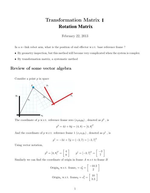
In a n−link robot arm, what is the position of end effector w.r.t. base reference frame ?<br />
• By geometry inspection, but this method will become very complicated when the system is complex<br />
• By transformation matrix, a systematic method<br />
Review of some vector algebra<br />
Consider a point p in space<br />
The coordinate of p w.r.t. reference frame zero (x 0 o 0 y 0 ) , denoted as p 0 , is<br />
p 0 = 4ˆx + 8ŷ = (4, 8) = [4, 8] T<br />
And the coordinate of p w.r.t. reference frame 1 (x 1 o 1 y 1 ) , denoted as p 1 , is<br />
Using vector notation,<br />
p 1 = −3ˆx + 7ŷ = (−3, 7) = [−3, 7] T<br />
[ ]<br />
p 0 = [4, 8] T 4<br />
=<br />
8<br />
p 1 = [−3, 7] T =<br />
[ −3<br />
7<br />
Similarly we can find the coordinate of origin in frame A w.r.t to frame B<br />
[ ] −10.3<br />
Origin 0 w.r.t. frame 1 = o 1 0 =<br />
2<br />
[ ] 10<br />
Origin 1 w.r.t. frame 0 = o 0 1 =<br />
3.3<br />
]<br />
1
Transforming between Frames<br />
How is p 0 related to p 1 ?<br />
[ ] 4<br />
p 0 + o 1 0 = +<br />
8<br />
[ ] 4<br />
p 0 =<br />
8<br />
[ −10.3<br />
2<br />
]<br />
=<br />
p 1 =<br />
[ −3<br />
7<br />
[ −6.3<br />
10<br />
]<br />
]<br />
≠ p 1 =<br />
[ −3<br />
7<br />
Because the frame 1 are rotated, so the 2 vectors are not equal by just addition<br />
<strong>Rotation</strong><br />
]<br />
Consider 2 frame as follow<br />
To express the unit vector (ˆx 1 , ŷ 1 ) w.r.t frame 0<br />
That is, express x 1 and y 1 using x 0 and y 0 :<br />
[ ] cos θ<br />
x 0 1 =<br />
sin θ<br />
y 0 1 =<br />
[ − sin θ<br />
cos θ<br />
Combine them into one matrix, the rotation matrix is thus<br />
[ ]<br />
cos θ − sin θ<br />
R1 0 =<br />
sin θ cos θ<br />
Thus, a point p w.r.t frame 1 p 1 and point p w.r.t. frame 0 p 0 are related by<br />
]<br />
That is<br />
p 0 = R 0 1p 1<br />
p expressed in<br />
frame 0<br />
unit vector of frame 1<br />
=<br />
expressed in frame 0<br />
[ cos θ − sin θ<br />
p 0 =<br />
sin θ cos θ<br />
]<br />
p 1<br />
p expressed in<br />
×<br />
frame 1<br />
2
Difference case for special θ<br />
Since θ is the angle between 2 x axis,<br />
When θ = 90 o R 0 1 =<br />
[ 0 −1<br />
1 0<br />
That is , first swap(x, y) , then make the new x as negative.<br />
]<br />
When θ = 180 o R 0 1 =<br />
[ −1 0<br />
0 −1<br />
]<br />
When θ = 270 o and 360 o , or any other angle, the logic is the same.<br />
Re-visiting the rotation matrix<br />
Since the rotation matrix is obtained by using the x 0 1 and y1 0 as it’s column vector<br />
⎡⎛<br />
R1 0 = ⎣⎝ x 0 1<br />
⎞ ⎛<br />
⎠ ⎝ y1<br />
0 ⎞⎤<br />
⎠⎦<br />
And x 0 1 , y1 0 is expressed using x 0 , y 0 , so they have 2 component<br />
[ ] [ x-component of<br />
x 0 x1 in frame 0<br />
x-component of<br />
1 =<br />
y 0 y1 in frame 0<br />
1 =<br />
y component of x 1 in frame 0<br />
y component of y 1 in frame 0<br />
Thus<br />
R 0 1 =<br />
[( x-component of x1 in frame 0<br />
y component of x 1 in frame 0<br />
) ( x-component of y1 in frame 0<br />
y component of y 1 in frame 0<br />
Recall that, we can extract a vector’s component by using dot product<br />
That is, for a vector ¯V = V xˆx + V y ŷ + V z ẑ<br />
)]<br />
]<br />
Thus<br />
R 0 1 =<br />
V x = ¯V · ˆx<br />
[( ) ( )]<br />
x1 · x 0 y1 · x 0<br />
x 1 · y 0 y 1 · y 0<br />
And therefore, we can use same logic to find R0<br />
1<br />
[( ) ( )]<br />
R0 1 x0 · x<br />
=<br />
1 y0 · x 1<br />
x 0 · y 1 y 0 · y 1<br />
These method are actually same as the graphical method, in graphical method, the diagram just<br />
show the projection of the vector component directly in the diagram. But when the diagram is very<br />
complicated, it is better to use the dot product method.<br />
3
Inverse, Transpose<br />
R 0 1 =<br />
[ ]<br />
x1 · x 0 y 1 · x 0<br />
x 1 · y 0 y 1 · y 0<br />
R 1 0 =<br />
[ ]<br />
x0 · x 1 y 0 · x 1<br />
x 0 · y 1 y 0 · y 1<br />
Since dot product is commutative, therefore, consider the transpose<br />
Therefore<br />
[ ]<br />
( ) T [ ] [ ]<br />
R<br />
0 T x1 · x<br />
1 =<br />
0 y 1 · x 0 x1 · x<br />
=<br />
0 x 1 · y 0 x0 · x<br />
=<br />
1 y 0 · x 1<br />
= R0<br />
1 x 1 · y 0 y 1 · y 0 y 1 · x 0 y 1 · y 0 x 0 · y 1 y 0 · y 1<br />
(<br />
R<br />
0<br />
1<br />
) T<br />
= R<br />
1<br />
0<br />
But since R 0 1 R 1 0 do the opposite thing, they are inverse to each other<br />
Thus<br />
(<br />
R<br />
0<br />
1<br />
) −1<br />
= R<br />
1<br />
0<br />
(<br />
R<br />
0<br />
1<br />
) −1<br />
=<br />
(<br />
R<br />
0<br />
1<br />
) T<br />
Small summary<br />
• ( R j i<br />
) T<br />
= R<br />
i<br />
j<br />
• ( R j i<br />
) −1<br />
= R<br />
i<br />
j<br />
• <strong>Rotation</strong> matrix is orthogonal : ( R j i<br />
3D cases<br />
) −1 ( )<br />
= R<br />
j T<br />
i<br />
The previous 2D case can be now treated as a 3D case<br />
4
In 3D case, the general rotation matrix for frame i w.r.t to frame j is<br />
⎡<br />
⎤<br />
x i · x j y i · x j z i · x j<br />
R j i = ⎣ x i · y j y i · y j z i · y j<br />
⎦<br />
x i · z j y i · z j z i · z j<br />
<strong>Rotation</strong> along x axis :<br />
⎡<br />
R1 0 (x, θ) = ⎣<br />
1 0 0<br />
0 cos θ − sin θ<br />
0 sin θ cos θ<br />
⎤<br />
⎦<br />
<strong>Rotation</strong> along y axis<br />
⎡<br />
R1 0 (y, θ) = ⎣<br />
cos θ 0 sin θ<br />
0 1 0<br />
− sin θ 0 cos θ<br />
⎤<br />
⎦<br />
<strong>Rotation</strong> along z axis :<br />
⎡<br />
R1 0 (z, θ) = ⎣<br />
cos θ − sin θ 0<br />
sin θ cos θ 0<br />
0 0 1<br />
⎤<br />
⎦<br />
Why rotation along y axis seems a little bit different in the sign<br />
The rotation is defined as positive if it is rotated anti-clockwise along that axis. In the case that<br />
rotation along the x,z axis, it fulfill this requirement. But for the case that rotate along y axis, the angle<br />
is clockwise, so a negative sign is added into the angle.<br />
5
Multiple <strong>Rotation</strong><br />
<strong>Rotation</strong> about the current frame<br />
For point p in base frame, after the first rotation , it rotate again<br />
Since p 2 and p 1 is related by<br />
And p 1 and p 0 is related by<br />
Thus<br />
And thus for<br />
What is p 2 w.r.t frame 0 ?<br />
p 1 = R2p 1 2<br />
p 0 = R1p 2 1<br />
p 0 = R1R 0 2p 1 2<br />
p 0 = R 0 2p 2<br />
That is, if<br />
R 0 2 = R 0 1R 1 2<br />
Frame0 R0 1<br />
−→ Frame1 R1 2<br />
−→... Rn−1 n<br />
−→Frame n<br />
And<br />
p 0 = R 0 1R 1 2...R n−2<br />
n−1Rn<br />
n−1 p n<br />
R 0 n = R 0 1R 1 2...R n−2<br />
n−1R n−1<br />
n<br />
−END−<br />
6