

caution - Toro
caution - Toro
caution - Toro

You also want an ePaper? Increase the reach of your titles
YUMPU automatically turns print PDFs into web optimized ePapers that Google loves.
Procedure for Rear Traction Circuit (RV) Relief Pressure<br />
Test<br />
1. Make sure hydraulic oil is at normal operating temperature<br />
by operating the machine for approximately 10<br />
minutes. Make sure the hydraulic tank is full.<br />
8. When testing is completed, disconnect pressure<br />
gauge from test port.<br />
1<br />
2. Park machine on a level surface with the cutting deck<br />
lowered and off. Make sure engine is off and the parking<br />
brake is engaged.<br />
CAUTION<br />
2<br />
Prevent personal injury and/or damage to equipment.<br />
Read all WARNINGS, CAUTIONS and Pre<strong>caution</strong>s<br />
for Hydraulic Testing at the beginning<br />
of this section.<br />
Figure 26<br />
1. 4WD control manifold<br />
2. Relief valve test port<br />
3. Connect a 1000 PSI (70 bar) gauge to test port on<br />
4WD control manifold under radiator (Fig. 26).<br />
4. After installing pressure gauge, start engine and run<br />
at idle speed. Check for hydraulic leakage and correct<br />
before proceeding with test.<br />
5. Operate the engine at full engine speed (2870 RPM).<br />
6. Operate the machine in 4WD (not transport speed)<br />
with the cutting deck lowered. Drive down a slope in a<br />
forward direction, decrease pressure on the traction<br />
pedal and monitor the pressure gauge. Pressure should<br />
increase until the relief valve (RV) lifts. Record test results.<br />
GAUGE READING TO BE 750 PSI (52 bar)<br />
(approximate).<br />
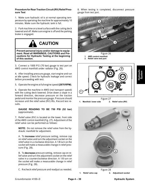
7. Relief valve (RV) is located on the lower, front side<br />
of the 4WD control manifold (Fig. 27). Adjustment of the<br />
relief valve can be performed as follows:<br />
1<br />
Figure 27<br />
1. Manifold: lower side 2. Relief valve (RV)<br />
2<br />
Hydraulic<br />
System<br />
NOTE: Do not remove the relief valve from the hydraulic<br />
manifold for adjustment.<br />
1<br />
A. To increase relief pressure setting, remove cap<br />
on relief valve and turn the adjustment socket on the<br />
relief valve in a clockwise direction. A 1/8 turn on the<br />
socket will make a measurable change in relief pressure<br />
(Fig. 28).<br />
B. To decrease pressure setting, remove cap on relief<br />
valve and turn the adjustment socket on the relief<br />
valve in a counterclockwise direction. A 1/8 turn on<br />
the socket will make a measurable change in relief<br />
pressure (Fig. 28).<br />
C. Recheck relief pressure and readjust as needed.<br />
Figure 28<br />
1. Relief valve cap 2. Adjustment socket<br />
2<br />
Groundsmaster 4100--D<br />
Page 4 - 39<br />
Hydraulic System


