

caution - Toro
caution - Toro
caution - Toro

You also want an ePaper? Increase the reach of your titles
YUMPU automatically turns print PDFs into web optimized ePapers that Google loves.
3. Slowly lower engine into the machine.<br />
4. Align engine to the engine supports and hydraulic<br />
pump input shaft. Secure engine to engine supports with<br />
cap screws, rebound washers and flange nuts.<br />
5. Secure hydraulic pump assembly to engine (see<br />
Pump Assembly Installation in the Service and Repairs<br />
section of Chapter 4 -- Hydraulic System).<br />
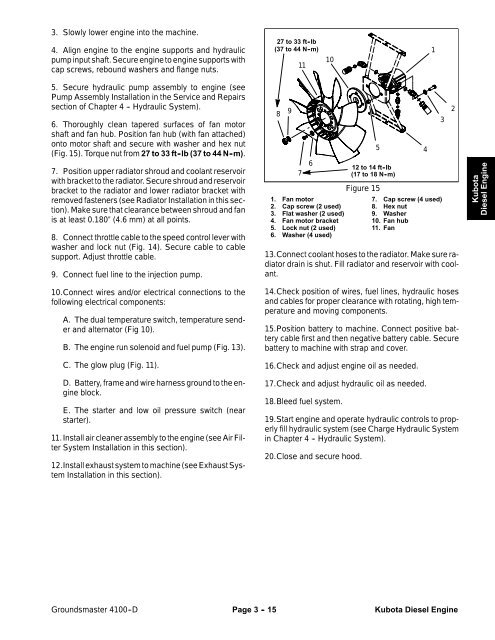
6. Thoroughly clean tapered surfaces of fan motor<br />
shaft and fan hub. Position fan hub (with fan attached)<br />
onto motor shaft and secure with washer and hex nut<br />
(Fig. 15). Torque nut from 27 to 33 ft -lb (37 to 44 N -m).<br />
7. Position upper radiator shroud and coolant reservoir<br />
with bracket to the radiator. Secure shroud and reservoir<br />
bracket to the radiator and lower radiator bracket with<br />
removed fasteners (see Radiator Installation in this section).<br />
Make sure that clearance between shroud and fan<br />
is at least 0.180” (4.6 mm) at all points.<br />
8. Connect throttle cable to the speed control lever with<br />
washer and lock nut (Fig. 14). Secure cable to cable<br />
support. Adjust throttle cable.<br />
9. Connect fuel line to the injection pump.<br />
10.Connect wires and/or electrical connections to the<br />
following electrical components:<br />
A. The dual temperature switch, temperature sender<br />
and alternator (Fig 10).<br />
B. The engine run solenoid and fuel pump (Fig. 13).<br />
C. The glow plug (Fig. 11).<br />
D. Battery, frame and wire harness ground to the engine<br />
block.<br />
E. The starter and low oil pressure switch (near<br />
starter).<br />
11.Install air cleaner assembly to the engine (see Air Filter<br />
System Installation in this section).<br />
12.Install exhaust system to machine (see Exhaust System<br />
Installation in this section).<br />
27 to 33 ft -lb<br />
(37to44N-m)<br />
10<br />
11<br />
8 9<br />
7<br />
6<br />
1. Fan motor<br />
2. Cap screw (2 used)<br />
3. Flat washer (2 used)<br />
4. Fan motor bracket<br />
5. Lock nut (2 used)<br />
6. Washer (4 used)<br />
12 to 14 ft -lb<br />
(17to18N-m)<br />
Figure 15<br />
5 4<br />
1<br />
7. Cap screw (4 used)<br />
8. Hex nut<br />
9. Washer<br />
10. Fan hub<br />
11. Fan<br />
13.Connect coolant hoses to the radiator. Make sure radiator<br />
drain is shut. Fill radiator and reservoir with coolant.<br />
14.Check position of wires, fuel lines, hydraulic hoses<br />
and cables for proper clearance with rotating, high temperature<br />
and moving components.<br />
15.Position battery to machine. Connect positive battery<br />
cable first and then negative battery cable. Secure<br />
battery to machine with strap and cover.<br />
16.Check and adjust engine oil as needed.<br />
17.Check and adjust hydraulic oil as needed.<br />
18.Bleed fuel system.<br />
19.Start engine and operate hydraulic controls to properly<br />
fill hydraulic system (see Charge Hydraulic System<br />
in Chapter 4 -- Hydraulic System).<br />
20.Close and secure hood.<br />
3<br />
2<br />
Kubota<br />
Diesel Engine<br />
Groundsmaster 4100--D Page 3 - 15 Kubota Diesel Engine


