

caution - Toro
caution - Toro
caution - Toro

Create successful ePaper yourself
Turn your PDF publications into a flip-book with our unique Google optimized e-Paper software.
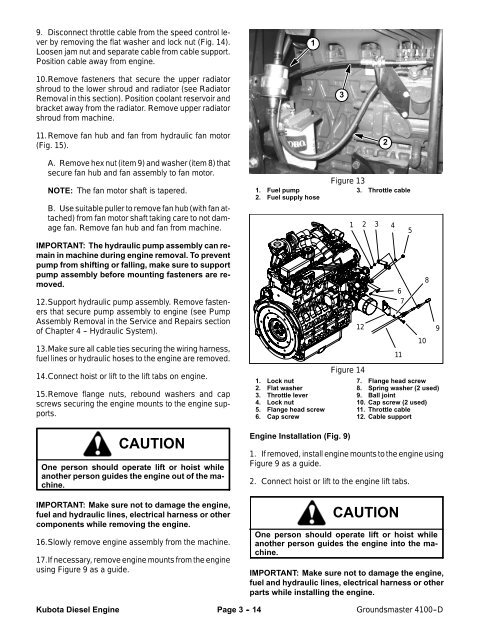
9. Disconnect throttle cable from the speed control lever<br />
by removing the flat washer and lock nut (Fig. 14).<br />
Loosen jam nut and separate cable from cable support.<br />
Position cable away from engine.<br />
1<br />
10.Remove fasteners that secure the upper radiator<br />
shroud to the lower shroud and radiator (see Radiator<br />
Removal in this section). Position coolant reservoir and<br />
bracket away from the radiator. Remove upper radiator<br />
shroud from machine.<br />
3<br />
11.Remove fan hub and fan from hydraulic fan motor<br />
(Fig. 15).<br />
A. Remove hex nut (item 9) and washer (item 8) that<br />
secure fan hub and fan assembly to fan motor.<br />
NOTE: The fan motor shaft is tapered.<br />
B. Use suitable puller to remove fan hub (with fan attached)<br />
from fan motor shaft taking care to not damage<br />
fan. Remove fan hub and fan from machine.<br />
IMPORTANT: The hydraulic pump assembly can remain<br />
in machine during engine removal. To prevent<br />
pump from shifting or falling, make sure to support<br />
pump assembly before mounting fasteners are removed.<br />
12.Support hydraulic pump assembly. Remove fasteners<br />
that secure pump assembly to engine (see Pump<br />
Assembly Removal in the Service and Repairs section<br />
of Chapter 4 -- Hydraulic System).<br />
13.Make sure all cable ties securing the wiring harness,<br />
fuel lines or hydraulic hoses to the engine are removed.<br />
14.Connect hoist or lift to the lift tabs on engine.<br />
15.Remove flange nuts, rebound washers and cap<br />
screws securing the engine mounts to the engine supports.<br />
1. Fuel pump<br />
2. Fuel supply hose<br />
1. Lock nut<br />
2. Flat washer<br />
3. Throttle lever<br />
4. Lock nut<br />
5. Flange head screw<br />
6. Cap screw<br />
Figure 13<br />
1<br />
3. Throttle cable<br />
12<br />
Figure 14<br />
2<br />
2 3 4<br />
6<br />
7<br />
11<br />
7. Flange head screw<br />
8. Spring washer (2 used)<br />
9. Ball joint<br />
10. Cap screw (2 used)<br />
11. Throttle cable<br />
12. Cable support<br />
5<br />
10<br />
8<br />
9<br />
CAUTION<br />
One person should operate lift or hoist while<br />
another person guides the engine out of the machine.<br />
IMPORTANT: Make sure not to damage the engine,<br />
fuel and hydraulic lines, electrical harness or other<br />
components while removing the engine.<br />
16.Slowly remove engine assembly from the machine.<br />
17.If necessary, remove engine mounts from the engine<br />
using Figure 9 as a guide.<br />
Engine Installation (Fig. 9)<br />
1. If removed, install engine mounts to the engine using<br />
Figure 9 as a guide.<br />
2. Connect hoist or lift to the engine lift tabs.<br />
CAUTION<br />
One person should operate lift or hoist while<br />
another person guides the engine into the machine.<br />
IMPORTANT: Make sure not to damage the engine,<br />
fuel and hydraulic lines, electrical harness or other<br />
parts while installing the engine.<br />
Kubota Diesel Engine<br />
Page 3 - 14<br />
Groundsmaster 4100--D


