

caution - Toro
caution - Toro
caution - Toro

You also want an ePaper? Increase the reach of your titles
YUMPU automatically turns print PDFs into web optimized ePapers that Google loves.
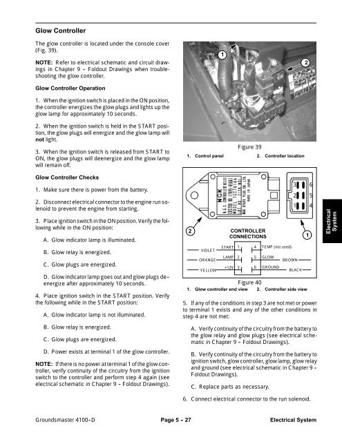
Glow Controller<br />
The glow controller is located under the console cover<br />
(Fig. 39).<br />
NOTE: Refer to electrical schematic and circuit drawings<br />
in Chapter 9 -- Foldout Drawings when troubleshooting<br />
the glow controller.<br />
Glow Controller Operation<br />
1. When the ignition switch is placed in the ON position,<br />
the controller energizes the glow plugs and lights up the<br />
glow lamp for approximately 10 seconds.<br />
2. When the ignition switch is held in the START position,<br />
the glow plugs will energize and the glow lamp will<br />
not light.<br />
3. When the ignition switch is released from START to<br />
ON, the glow plugs will deenergize and the glow lamp<br />
will remain off.<br />
1<br />
Figure 39<br />
1. Control panel 2. Controller location<br />
2<br />
Glow Controller Checks<br />
1. Make sure there is power from the battery.<br />
2. Disconnect electrical connector to the engine run solenoid<br />
to prevent the engine from starting.<br />
3. Place ignition switch in the ON position. Verify the following<br />
while in the ON position:<br />
A. Glow indicator lamp is illuminated.<br />
B. Glow relay is energized.<br />
C. Glow plugs are energized.<br />
D. Glow indicator lamp goes out and glow plugs de--<br />
energize after approximately 10 seconds.<br />
4. Place ignition switch in the START position. Verify<br />
the following while in the START position:<br />
A. Glow indicator lamp is not illuminated.<br />
B. Glow relay is energized.<br />
C. Glow plugs are energized.<br />
D. Power exists at terminal 1 of the glow controller.<br />
NOTE: If there is no power at terminal 1 of the glow controller,<br />
verify continuity of the circuitry from the ignition<br />
switch to the controller and perform step 4 again (see<br />
electrical schematic in Chapter 9 -- Foldout Drawings).<br />
2<br />
VIOLET<br />
ORANGE<br />
YELLOW<br />
START<br />
CONTROLLER<br />
CONNECTIONS<br />
LAMP<br />
+12V<br />
1<br />
2<br />
3<br />
TEMP (not used)<br />
GLOW<br />
GROUND<br />
Figure 40<br />
1. Glow controller end view 2. Controller side view<br />
3<br />
2<br />
1<br />
BROWN<br />
BLACK<br />
5. If any of the conditions in step 3 are not met or power<br />
to terminal 1 exists and any of the other conditions in<br />
step 4 are not met:<br />
A. Verify continuity of the circuitry from the battery to<br />
the glow relay and glow plugs (see electrical schematic<br />
in Chapter 9 -- Foldout Drawings).<br />
B. Verify continuity of the circuitry from the battery to<br />
ignition switch, glow controller, glow lamp, glow relay<br />
and ground (see electrical schematic in Chapter 9 --<br />
Foldout Drawings).<br />
C. Replace parts as necessary.<br />
6. Connect electrical connector to the run solenoid.<br />
4<br />
5<br />
6<br />
1<br />
6<br />
5<br />
4<br />
Electrical<br />
System<br />
Groundsmaster 4100--D Page 5 - 27 Electrical System


