

Multi Pro 5700 - Toro
Multi Pro 5700 - Toro
Multi Pro 5700 - Toro

Create successful ePaper yourself
Turn your PDF publications into a flip-book with our unique Google optimized e-Paper software.
Removal (Fig. 34)<br />
1. Park machine on a level surface, stop engine, engage<br />
parking brake, and remove key from the ignition<br />
switch.<br />
CAUTION<br />
Rotate steering wheel and depress traction pedal<br />
in both forward and reverse to relieve hydraulic<br />
system pressure and to avoid injury from<br />
pressurized hydraulic oil.<br />
5. Remove plugs from hydraulic lines, fittings, and<br />
ports. Lubricate new o–rings and attach hydraulic hoses<br />
to wheel motor.<br />
6. If right side wheel motor was removed, plug speed<br />
sensor connector into machine wiring harness.<br />
7. Check fluid level in hydraulic oil reservoir and adjust<br />
as required (see Operator’s Manual).<br />
8. Operate machine and inspect for leaks.<br />
2. Operate all hydraulic controls to relieve hydraulic<br />
system pressure.<br />
3<br />
2<br />
3. Read the General Precautions for Removing and<br />
Installing Hydraulic System Components at the beginning<br />
of the Service and Repairs section of this chapter.<br />
4. To prevent contamination of hydraulic system during<br />
motor removal, thoroughly clean exterior of motor and<br />
fittings.<br />
NOTE: To ease reassembly, tag the hydraulic hoses to<br />
show their correct position on the wheel motor.<br />
5. Disconnect hydraulic hoses from fittings on wheel<br />
motor. Put caps or plugs on hydraulic lines, fittings, and<br />
ports to prevent contamination.<br />
6. If right side wheel motor is being removed, unplug<br />
speed sensor connector from machine wiring harness.<br />
IMPORTANT: Before loosening fasteners, support<br />
wheel motor to prevent motor from falling.<br />
7. Support the pump assembly to prevent it from falling.<br />
Remove two (2) cap screws and flat washers that secure<br />
wheel motor to brake and planetary assemblies. Remove<br />
wheel motor from machine.<br />
Installation (Fig. 34)<br />
1. If splined brake shaft was removed from brake assembly,<br />
make sure that the stepped end of the shaft is<br />
aligned toward the hydraulic wheel motor (Fig. 35). Also,<br />
make sure that splines engage rotating discs in brake<br />
assembly.<br />
2. Position wheel motor to brake assembly.<br />
3. Align splines on motor shaft and splined brake shaft.<br />
Slide motor to brake assembly.<br />
4. Secure motor to brake and planetary assemblies<br />
with cap screws and flat washers. Torque cap screws 60<br />
ft–lb (81 N–m).<br />
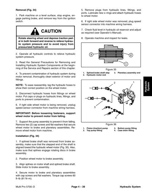
Figure 35<br />
1. Splined brake shaft step 3. Planetary assembly end<br />
2. Hydraulic motor end<br />
3<br />
2<br />
4<br />
Figure 36<br />
1. Piston (traction) pump 3. Bottom pump fitting<br />
2. Top pump fitting 4. Case drain fitting<br />
1<br />
1<br />
Hydraulic<br />
System<br />
<strong>Multi</strong> <strong>Pro</strong> <strong>5700</strong>–D Page 4 – 39 Hydraulic System


