

Multi Pro 5700 - Toro
Multi Pro 5700 - Toro
Multi Pro 5700 - Toro

Create successful ePaper yourself
Turn your PDF publications into a flip-book with our unique Google optimized e-Paper software.
3. Operate all hydraulic controls to relieve hydraulic<br />
system pressure.<br />
4. Remove traction cable ball joint from control plate on<br />
piston pump by removing lock nut (Fig. 32). Remove cap<br />
screw from control plate. Locate and retrieve three (3)<br />
flat washers (Fig. 33).<br />
5. Disconnect two (2) wires from neutral switch on piston<br />
pump (Fig. 32).<br />
6. Remove flange head screw and flange nut that secures<br />
R--clamp and right side brake cable to pump assembly<br />
(Fig. 32).<br />
7. Read the General Precautions for Removing and<br />
Installing Hydraulic System Components at the beginning<br />
of the Service and Repairs section of this chapter.<br />
NOTE: To ease reassembly, tag hydraulic hoses to<br />
show their correct position on the pump assembly.<br />
6. Connect two (2) wires to neutral switch on piston<br />
pump (Fig. 32).<br />
7. Remove plugs or caps from disconnected hydraulic<br />
hoses and ports of the pump assembly. Lubricate new<br />
O--rings and install fittings and hoses to correct location<br />
on gear and piston pumps.<br />
8. Secure R--clamp and right side brake cable to pump<br />
assembly with flange head screw and flange nut.<br />
9. Install new hydraulic oil filter and fill hydraulic reservoir<br />
with correct oil (see Operator’s Manual).<br />
10.<strong>Pro</strong>perly fill hydraulic system (see Charge Hydraulic<br />
System in the Service and Repairs section of this chapter).<br />
11.Stop engine and check for hydraulic oil leaks. Check<br />
hydraulic reservoir oil level.<br />
8. Put a drain pan below the pump assembly. Remove<br />
hydraulic hoses and fittings connected to piston and<br />
gear pumps. Put plugs or caps on disconnected hydraulic<br />
hoses to prevent contamination of the system. Put<br />
plugs in open ports of pumps.<br />
9. Support the pump assembly to prevent it from falling.<br />
Remove two (2) cap screws, lock washers and flat<br />
washers that retain pump assembly to engine bell housing.<br />
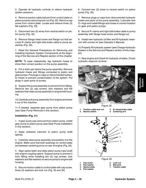
1<br />
2<br />
4<br />
3<br />
Hydraulic<br />
System<br />
10.Carefully pull pump assembly from engine and lower<br />
it out of the machine.<br />
11.If needed, separate gear pump from piston pump<br />
(see Gear Pump Removal in this section).<br />
Installation (Fig. 31)<br />
1. Traction cable lock nut<br />
2. Neutral switch<br />
Figure 32<br />
3. R -clamp/brake cable<br />
4. Centering arm<br />
1. If gear pump was removed from piston pump, install<br />
gear pump to piston pump (see Gear Pump Installation<br />
in this section).<br />
2. Apply antiseize lubricant to piston pump shaft<br />
splines.<br />
3. Carefully raise pump assembly and position it to the<br />
engine. Make sure that both bushings on control plate<br />
are between centering arms on rear of engine (Fig. 32).<br />
4. Align spline teeth and slide piston pump input shaft<br />
into engine coupling spline. Support pump to prevent it<br />
from falling while installing two (2) cap screws, lock<br />
washers and flat washers to secure pump to engine bell<br />
housing.<br />
5. Secure traction cable to control plate with cap screw,<br />
three (3) washers and lock nut (Fig. 32 and 33).<br />
1. Cap screw<br />
2. Flat washer<br />
3. Neutral plate<br />
4. Flat washer<br />
7<br />
6<br />
Figure 33<br />
1<br />
2<br />
4<br />
5<br />
3<br />
5. Lock nut<br />
6. Ball joint<br />
7. Traction cable<br />
<strong>Multi</strong> <strong>Pro</strong> <strong>5700</strong>--D<br />
Page 4 - 35<br />
Hydraulic System


