

Multi Pro 5700 - Toro
Multi Pro 5700 - Toro
Multi Pro 5700 - Toro

Create successful ePaper yourself
Turn your PDF publications into a flip-book with our unique Google optimized e-Paper software.
Spray Pump Drive Circuit Relief Pressure Test<br />
1. Make sure hydraulic oil is at normal operating temperature<br />
by operating the machine for approximately 10<br />
minutes. Make sure the hydraulic tank is full.<br />
2. Park machine on a level surface, stop engine, engage<br />
parking brake, and remove key from the ignition<br />
switch. After turning engine off, operate all hydraulic<br />
controls to relieve hydraulic system pressure.<br />
CAUTION<br />
8. Open control valve on tester, slow engine speed and<br />
shut off engine. Record test results.<br />
A. If relief pressure specification is not met, adjust<br />
spray circuit relief valve (Fig. 19) (see Adjust Relief<br />
Valve in the Adjustments section of this Chapter). After<br />
adjustment, retest relief valve pressure.<br />
B. If relief pressure specification is met, disconnect<br />
tester from tee fitting and spray circuit pressure<br />
hose. Reconnect pressure hose to tee fitting.<br />
Prevent personal injury and/or damage to equipment.<br />
Read all WARNINGS, CAUTIONS, and Precautions<br />
for Hydraulic Testing at the beginning<br />
of this section.<br />
4<br />
1<br />
2<br />
IMPORTANT: Make sure that oil flow indicator arrow<br />
on the flow meter is showing that oil will flow from<br />
the pump, through the tester, and into the hydraulic<br />
hose.<br />
3. Clean hydraulic fittings and install tester with pressure<br />
gauges and flow meter in series between the gear<br />
pump tee fitting and the spray motor circuit pressure<br />
hose (Fig. 19). Make sure the tester flow control<br />
valve is completely open.<br />
4. After installing tester, start engine and run at idle<br />
speed. Check for hydraulic leakage and correct before<br />
proceeding with test.<br />
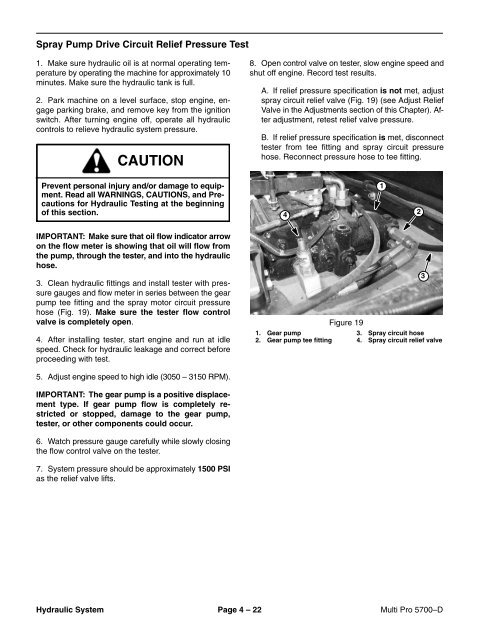
Figure 19<br />
1. Gear pump 3. Spray circuit hose<br />
2. Gear pump tee fitting 4. Spray circuit relief valve<br />
3<br />
5. Adjust engine speed to high idle (3050 – 3150 RPM).<br />
IMPORTANT: The gear pump is a positive displacement<br />
type. If gear pump flow is completely restricted<br />
or stopped, damage to the gear pump,<br />
tester, or other components could occur.<br />
6. Watch pressure gauge carefully while slowly closing<br />
the flow control valve on the tester.<br />
7. System pressure should be approximately 1500 PSI<br />
as the relief valve lifts.<br />
Hydraulic System Page 4 – 22 <strong>Multi</strong> <strong>Pro</strong> <strong>5700</strong>–D


