

Multi Pro 5700 - Toro
Multi Pro 5700 - Toro
Multi Pro 5700 - Toro

Create successful ePaper yourself
Turn your PDF publications into a flip-book with our unique Google optimized e-Paper software.
Diagnostic Display<br />
The Sonic Boom System is equipped with an electronic<br />
control unit (ECU) which controls machine sonic boom<br />
electrical functions. The ECU monitors various input<br />
switches (e.g. boom actuator switches, sonic boom sensors)<br />
and energizes outputs to actuate relays for appropriate<br />
machine functions.<br />
For the ECU to control the machine as desired, each of<br />
the inputs (switches and sensors) and outputs (relays)<br />
must be connected and functioning properly.<br />
The Diagnostic Display (see Special Tools in this chapter)<br />
is a tool to help the technician verify correct electrical<br />
functions of the machine.<br />
IMPORTANT: The Diagnostic Display must not be<br />
left connected to the machine. It is not designed to<br />
withstand the environment of the machine’s every<br />
day use. When use of the Diagnostic Display is completed,<br />
disconnect it from the machine and reconnect<br />
loopback connector to harness connector. The<br />
machine will not operate without the loopback connector<br />
installed on the harness. Store the Diagnostic<br />
Display in a dry, secure, indoor location and not<br />
on machine.<br />
Verify Diagnostic Display Input Functions<br />
1. Park vehicle on a level surface, stop the engine and<br />
apply the parking brake.<br />
2. Locate Sonic Boom wire harness communication<br />
port and loopback connector under the vehicle dash<br />
panel. Carefully unplug loopback connector from harness<br />
connector.<br />
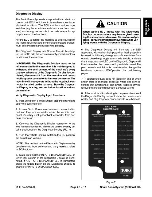
3. Connect the Diagnostic Display connector to the<br />
wire harness connector. Make sure correct overlay decal<br />
is positioned on the Diagnostic Display (Fig. 7).<br />
4. Turn the vehicle ignition switch to the ON position,<br />
but do not start vehicle.<br />
NOTE: The red text on the Diagnostic Display overlay<br />
decal refers to input switches and the green text refers<br />
to ECU outputs.<br />
5. Make sure that the “INPUTS DISPLAYED” LED, on<br />
lower right column of the Diagnostic Display, is illuminated.<br />
If “OUTPUTS DISPLAYED” LED is illuminated,<br />
press the toggle button on the Diagnostic Display to<br />
change to “INPUTS DISPLAYED” LED.<br />
CAUTION<br />
When testing ECU inputs with the Diagnostic<br />
Display, boom actuators may be energized causing<br />
the spray booms to move. Be cautious of potential<br />
sprayer component movement while verifying<br />
inputs with the Diagnostic Display.<br />
6. The Diagnostic Display will illuminate the LED<br />
associated with each of the inputs when that input switch<br />
is closed. Individually, change each of the switches from<br />
open to closed (e.g. toggle sonic mode switch), and note<br />
that the appropriate LED on the Diagnostic Display will<br />
illuminate when the corresponding switch is closed. Repeat<br />
on each switch that is possible to be changed by<br />
hand (see Inputs and LED Operation chart on following<br />
page).<br />
7. If appropriate LED does not toggle on and off when<br />
switch state is changed, check all wiring and connections<br />
to that switch and/or test switch. Replace any defective<br />
switches and repair any damaged wiring.<br />
8. After input functions testing is complete, disconnect<br />
the Diagnostic Display connector from the harness connector<br />
and plug loopback connector into wire harness.<br />
Sonic Boom<br />
System<br />
Figure 7<br />
<strong>Multi</strong> <strong>Pro</strong> <strong>5700</strong>--D Page 7.1 - 17 Sonic Boom System (Optional Kit)


