

Multi Pro 5700 - Toro
Multi Pro 5700 - Toro
Multi Pro 5700 - Toro

You also want an ePaper? Increase the reach of your titles
YUMPU automatically turns print PDFs into web optimized ePapers that Google loves.
IMPORTANT: Boom valve motors may have a fuse<br />
for circuit protection. Make sure that correct fuse is<br />
installed in the in -line fuse holder located in the<br />
boom valve motor harness.<br />
1<br />
SERIAL NUMBER BELOW 310000000<br />
2<br />
3<br />
4<br />
The boom control switches on the operator spray console<br />
are used to energize the boom valve motors and<br />
open the boom valves. The open boom valves allow system<br />
flow to reach the appropriate boom section (right,<br />
center or left). Two (2) styles of boom valve motors have<br />
been used on <strong>Multi</strong> <strong>Pro</strong> <strong>5700</strong>--D machines. Both of these<br />
motor styles are shown in Figure 24.<br />
7<br />
5<br />
IMPORTANT: Make sure to remove and neutralize<br />
chemicals from spray components before disassembly.<br />
Wear protective clothing, chemical resistant<br />
gloves, and eye protection during repair.<br />
Disassembly (Fig. 24)<br />
1. Remove boom valve motor assembly from machine<br />
(see Spray Control Assembly in this section).<br />
2. Separate boom valve motors as needed using Figure<br />
24 as a guide. Discard all removed O--rings and gaskets.<br />
1. Agitation valve motor<br />
2. LH boom valve motor<br />
3. Center boom valve motor<br />
4. RH boom valve motor<br />
6<br />
Figure 25<br />
5. RH boom supply hose<br />
6. Center boom supply<br />
7. LH boom supply hose<br />
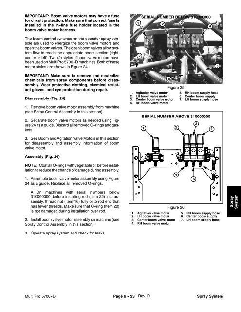
SERIAL NUMBER ABOVE 310000000<br />
1<br />
2<br />
3<br />
4<br />
3. See Boom and Agitation Valve Motors in this section<br />
for disassembly and assembly information of boom<br />
valve motor.<br />
Assembly (Fig. 24)<br />
NOTE: Coat all O--rings with vegetable oil before installation<br />
to reduce the chance of damage during assembly.<br />
1. Assemble boom valve motor assembly using Figure<br />
24 as a guide. Replace all removed O--rings.<br />
7<br />
6<br />
5<br />
A. On machines with serial numbers below<br />
310000000, before installing rod (Item 22) into assembly,<br />
thread nut (item 16) fully onto rod end that<br />
has fewer threads. Make sure that O--ring (Item 20)<br />
is not damaged during installation over rod.<br />
2. Install boom valve motor assembly on machine (see<br />
Spray Control Assembly in this section).<br />
3. Operate spray system and check for leaks.<br />
Figure 26<br />
1. Agitation valve motor<br />
2. LH boom valve motor<br />
3. Center boom valve motor<br />
4. RH boom valve motor<br />
5. RH boom supply hose<br />
6. Center boom supply<br />
7. LH boom supply hose<br />
Spray<br />
System<br />
Rev. D<br />
<strong>Multi</strong> <strong>Pro</strong> <strong>5700</strong>--D Page 6 - 23 Spray System


