

Golf Irrigation Catalog - Toro
Golf Irrigation Catalog - Toro
Golf Irrigation Catalog - Toro

Create successful ePaper yourself
Turn your PDF publications into a flip-book with our unique Google optimized e-Paper software.
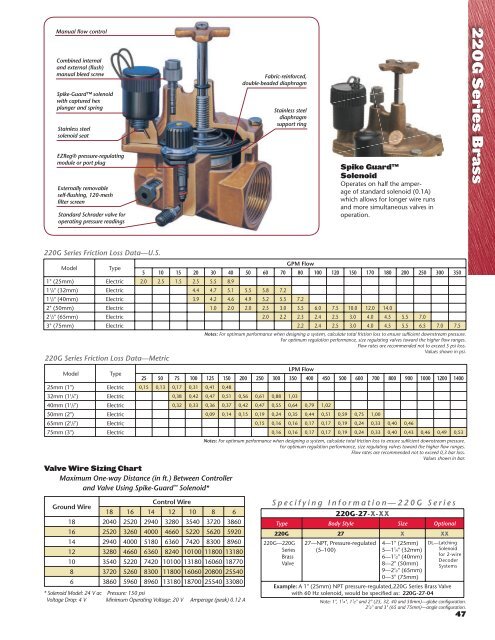
Manual flow control<br />
Combined internal<br />
and external (flush)<br />
manual bleed screw<br />
Spike-Guard solenoid<br />
with captured hex<br />
plunger and spring<br />
Stainless steel<br />
solenoid seat<br />
EZReg® pressure-regulating<br />
module or port plug<br />
Externally removable<br />
self-flushing, 120-mesh<br />
filter screen<br />
Standard Schrader valve for<br />
operating pressure readings<br />
Fabric-reinforced,<br />
double-beaded diaphragm<br />
Stainless steel<br />
diaphragm<br />
support ring<br />
Spike Guard<br />
Solenoid<br />
Operates on half the amperage<br />
of standard solenoid (0.1A)<br />
which allows for longer wire runs<br />
and more simultaneous valves in<br />
operation.<br />
220G Series Brass<br />
220G Series Friction Loss Data—U.S.<br />
Model<br />
Type<br />
1" (25mm) Electric 2.0 2.5 1.5 2.5 5.5 8.9<br />
Specifying Information—220G Series<br />
220G-27-X-XX<br />
Type Body Style Size Optional<br />
220G 27 X XX<br />
220G—220G<br />
Series<br />
Brass<br />
Valve<br />
GPM Flow<br />
5 10 15 20 30 40 50 60 70 80 100 120 150 170 180 200 250 300 350<br />
1 1 /4" (32mm) Electric 4.4 4.7 5.1 5.5 5.8 7.2<br />
1 1 /2" (40mm) Electric 3.9 4.2 4.6 4.9 5.2 5.5 7.2<br />
2" (50mm) Electric 1.0 2.0 2.0 2.5 3.0 3.5 6.0 7.5 10.0 12.0 14.0<br />
2 1 /2" (65mm) Electric 2.0 2.2 2.3 2.4 2.5 3.0 4.0 4.5 5.5 7.0<br />
3" (75mm) Electric 2.2 2.4 2.5 3.0 4.0 4.5 5.5 6.5 7.0 7.5<br />
220G Series Friction Loss Data—Metric<br />
Model<br />
Type<br />
25mm (1") Electric 0,15 0,13 0,17 0,31 0,41 0,48<br />
Notes: For optimum performance when designing a system, calculate total friction loss to ensure sufficient downstream pressure.<br />
For optimum regulation performance, size regulating valves toward the higher flow ranges.<br />
Flow rates are recommended not to exceed 5 psi loss.<br />
Values shown in psi.<br />
LPM Flow<br />
25 50 75 100 125 150 200 250 300 350 400 450 500 600 700 800 900 1000 1200 1400<br />
32mm (1 1 /4") Electric 0,38 0,42 0,47 0,51 0,56 0,61 0,88 1,03<br />
40mm (1 1 /2") Electric 0,32 0,33 0,36 0,37 0,42 0,47 0,55 0,64 0,79 1,02<br />
50mm (2") Electric 0,09 0,14 0,15 0,19 0,24 0,35 0,44 0,51 0,59 0,75 1,00<br />
65mm (2 1 /2") Electric 0,15 0,16 0,16 0,17 0,17 0,19 0,24 0,33 0,40 0,46<br />
75mm (3") Electric 0,16 0,16 0,17 0,17 0,19 0,24 0,33 0,40 0,43 0,46 0,49 0,53<br />
Notes: For optimum performance when designing a system, calculate total friction loss to ensure sufficient downstream pressure.<br />
For optimum regulation performance, size regulating valves toward the higher flow ranges.<br />
Flow rates are recommended not to exceed 0,3 bar loss.<br />
Values shown in bar.<br />
Valve Wire Sizing Chart<br />
Maximum One-way Distance (in ft.) Between Controller<br />
and Valve Using Spike-Guard Solenoid*<br />
Ground Wire<br />
Control Wire<br />
18 16 14 12 10 8 6<br />
18 2040 2520 2940 3280 3540 3720 3860<br />
16 2520 3260 4000 4660 5220 5620 5920<br />
14 2940 4000 5180 6360 7420 8300 8960<br />
12 3280 4660 6360 8240 10100 11800 13180<br />
10 3540 5220 7420 10100 13180 16060 18770<br />
8 3720 5260 8300 11800 16060 20800 25540<br />
6 3860 5960 8960 13180 18700 25540 33080<br />
* Solenoid Model: 24 V ac Pressure: 150 psi<br />
Voltage Drop: 4 V Minimum Operating Voltage: 20 V Amperage (peak) 0.12 A<br />
27—NPT, Pressure-regulated<br />
(5–100)<br />
4—1" (25mm)<br />
5—1 1 ⁄4" (32mm)<br />
6—1 1 ⁄2" (40mm)<br />
8—2" (50mm)<br />
9—2 1 ⁄2" (65mm)<br />
0—3" (75mm)<br />
DL—Latching<br />
Solenoid<br />
for 2-wire<br />
Decoder<br />
Systems<br />
Example: A 1" (25mm) NPT pressure-regulated,220G Series Brass Valve<br />
with 60 Hz solenoid, would be specified as: 220G-27-04<br />
Note: 1", 1 1 ⁄4", 1 1 ⁄2" and 2" (25, 32, 40 and 50mm)—globe configuration.<br />
2 1 ⁄2" and 3" (65 and 75mm)—angle configuration.<br />
47


