

supersonic combustion of kerosene/h2-mixtures in a model scramjet
supersonic combustion of kerosene/h2-mixtures in a model scramjet
supersonic combustion of kerosene/h2-mixtures in a model scramjet

Create successful ePaper yourself
Turn your PDF publications into a flip-book with our unique Google optimized e-Paper software.
SUPERSONIC COMBUSTION<br />
OF KEROSENE/H 2 -MIXTURES IN A MODEL<br />
SCRAMJET COMBUSTOR<br />
C. GRUENIG * and F. MAYINGER<br />
Institute A for Thermodynamics, Technical University Munich,<br />
D-85747 Garch<strong>in</strong>g / Germany<br />
Liquid hydrocarbon <strong>supersonic</strong> <strong>combustion</strong> has been experimentally <strong>in</strong>vestigated. Kerosene was<br />
burnt <strong>in</strong> a steady, vitiated Mach 2.15 - air flow <strong>of</strong> a <strong>model</strong> <strong>scramjet</strong> combustor. The fuel is <strong>in</strong>jected<br />
<strong>in</strong>to the <strong>supersonic</strong> air stream by means <strong>of</strong> pylons. The effervescent atomisation method has been<br />
employed such that the liquid fuel is <strong>in</strong>jected as a spray. By means <strong>of</strong> the Mie scatter<strong>in</strong>g technique<br />
the fuel jet structure was visualised and the evaporation rate estimated.<br />
The mechanisms <strong>of</strong> ignition and <strong>combustion</strong> <strong>of</strong> the <strong>kerosene</strong>/H 2 -mixture were studied and<br />
compared with the case <strong>of</strong> hydrogen <strong>combustion</strong>. Combustor ignition limits have been determ<strong>in</strong>ed.<br />
Fuel-specific <strong>combustion</strong> phenomena are discussed. It was found that for the <strong>kerosene</strong> <strong>combustion</strong> a<br />
gas dynamic feedback mechanism strongly affects the <strong>supersonic</strong> <strong>combustion</strong> process.<br />
Keywords: Supersonic <strong>combustion</strong>; <strong>kerosene</strong>; <strong>scramjet</strong>; self-ignition; gas dynamic feedback<br />
1 INTRODUCTION<br />
Supersonic <strong>combustion</strong> ramjets are an attractive option to propel future hypersonic flight systems<br />
(e.g. Hunt and Rausch, 1998; Scuderi et al., 1998; Maita and Kubota, 1998; Grallert and Herrmann,<br />
1998). Most research activities focus on hydrogen-fuelled <strong>scramjet</strong>s as hydrogen is the fuel <strong>of</strong><br />
choice for high speed flight because <strong>of</strong> its properties such as its high heat <strong>of</strong> <strong>combustion</strong>, its high<br />
molecular diffusion velocity, its ability turn burn at lowest pressures, and – what is important for<br />
the application <strong>in</strong> hypersonic flight vehicles – its high specific heat, i.e., its cool<strong>in</strong>g capacity. In<br />
fact, the cool<strong>in</strong>g capacity is one <strong>of</strong> the most important porperties that strongly <strong>in</strong>fuences the fuel<br />
selection for high speed flight systems.<br />
For flight Mach numbers below appr. 8 liquid hydrocarbon fuels possess sufficient cool<strong>in</strong>g<br />
capacity (Hunt and Rausch, 1998; Hunt et al., 1997). Hence, below M 0 = 8 the advantages <strong>of</strong> liquid<br />
hydrocarbon fuels (high volumetric specific impulse ρ fuel ∗I sp which is <strong>of</strong> special importance for<br />
narrow body and/or small scale flight systems) can be utilised. S<strong>in</strong>ce the early n<strong>in</strong>eties there has<br />
been an <strong>in</strong>crease <strong>in</strong> research <strong>in</strong> the field <strong>of</strong> hydrocarbon <strong>supersonic</strong> <strong>combustion</strong> (e.g. Avrashkov et<br />
al., 1990; Avrashkov et al., 1992; V<strong>in</strong>ogradov et al., 1992; Romankov and Starost<strong>in</strong>, 1993; Owens<br />
et al., 1997; Owens et al., 1998, Bouchez et al., 1998; Semenov et al., 1998).<br />
* Correspond<strong>in</strong>g Author: Email: carolus.gruenig@avl.com
In this paper we describe research activities that <strong>in</strong> particular supplement the work by Avrashkov<br />
et al. (1990 and 1992) at the Moscow Aviation Institute. The basis <strong>of</strong> the present paper has been<br />
laid by a jo<strong>in</strong>t co-operation with this <strong>in</strong>stitute (Gruenig et al., 1996). The aim is to get <strong>in</strong>sight <strong>in</strong> the<br />
processes <strong>of</strong> the <strong>kerosene</strong>/air mix<strong>in</strong>g, the fuel evaporation, and the ignition and <strong>supersonic</strong><br />
<strong>combustion</strong>. Furthermore, fuel-specific <strong>combustion</strong> aspects are to be explored.<br />
2 EXPERIMENTAL DETAILS<br />
The experiments have been performed <strong>in</strong> the <strong>supersonic</strong> flow channel <strong>of</strong> the Institute A for<br />
Thermodynamics at the Technical University Munich. This is a blow-down facility supplied with<br />
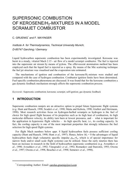
reservoir conditions p 0 = 13.5 bar, T 0 = 293 K and m& max = 1.5 kg/s. Figure 1 shows a schematic <strong>of</strong><br />
the flow channel.<br />
FIGURE 1<br />
Schematic <strong>of</strong> <strong>supersonic</strong> <strong>combustion</strong> test facility<br />
In the preheater the air total temperature <strong>of</strong> is raised by pre<strong>combustion</strong> <strong>of</strong> hydrogen. To<br />
compensate for the oxygen consumption <strong>in</strong> the preheater, additional oxygen is supplied to the air<br />
flow approximately 100 hydraulic diameter upstream <strong>of</strong> the preheater. The preheated air passes<br />
through a Laval-nozzle where<strong>in</strong> it is accelerated to M = 2.15. Typical flow conditions at the<br />
entrance <strong>of</strong> the <strong>supersonic</strong> test combustor are summarised <strong>in</strong> Table I. These conditions<br />
approximately correspond to flight Mach number M 0 = 6.5 at altitude h = 23.5 km on a<br />
representative trajectory <strong>of</strong> a transatmospheric accelerator, assum<strong>in</strong>g a typical <strong>in</strong>let compression<br />
ratio (Billig, 1996).<br />
M<br />
[-]<br />
T 0<br />
[K]<br />
T<br />
[K]<br />
m&<br />
[kg/s<br />
]<br />
p<br />
[bar]<br />
u<br />
[m/s]<br />
2.15 1700 1000 0.33 1.0 1310 3.3∗10 5 0.705 0.188 0.107<br />
Re<br />
[-]<br />
w N2<br />
[-]<br />
w O2<br />
[-]<br />
w H2O<br />
[-]<br />
TABLE 1<br />
Flow conditions at entrance <strong>of</strong> test combustor
Due to the pre<strong>combustion</strong> there is a significant amount <strong>of</strong> water <strong>in</strong> the test air. By means <strong>of</strong><br />
spectral analysis the test air was checked for residual radical concentrations. For T 0,air < 1750 K no<br />
radicals could be detected. However, m<strong>in</strong>or concentrations can not be totally excluded.<br />
Nevertheless, even tak<strong>in</strong>g <strong>in</strong>to account possible radical contam<strong>in</strong>ations the measurements will yield<br />
valuable results as Mitani (1995) showed that radical contam<strong>in</strong>ations have the same effects on the<br />
<strong>scramjet</strong> behaviour as a higher temperature <strong>of</strong> radical-free air.<br />
The <strong>supersonic</strong> test combustor (see Figure 1) is <strong>of</strong> rectangular cross section (width = 25 mm,<br />
height = 27.5 mm at the entrance). The overall length is 645 mm. The bottom combustor wall<br />
consists <strong>of</strong> modules <strong>of</strong> vary<strong>in</strong>g expansion angles. Modules with expansions angles <strong>of</strong> 0°, 2°, 4°, 6°<br />
and 12° are available so that different combustor area ratios A exit /A entrance can be provided. The fuel<br />
(<strong>kerosene</strong> Jet A-1) is <strong>in</strong>jected 75 mm downstream <strong>of</strong> the combustor entrance by means <strong>of</strong> a pylon.<br />
Further downstream provision is made to temporarily <strong>in</strong>ject N 2 from both the top and bottom<br />
combustor wall to support the combustor ignition if necessary.<br />
Along the top combustor wall the static pressure p w is measured at seven locations. The static<br />
pressure <strong>in</strong> the flow is ma<strong>in</strong>ly <strong>in</strong>fluenced by the <strong>combustion</strong> heat release and the combustor<br />
geometry (Shapiro, 1953; Zierep, 1975). The heat removal by radiative and convective heat transfer<br />
to the combustor walls is much smaller than the heat <strong>in</strong>put by <strong>combustion</strong> (Gruenig, 1998).<br />
Moreover, pressure measurements <strong>in</strong> case <strong>of</strong> <strong>in</strong>ert gas <strong>in</strong>jection <strong>in</strong>to the preheated air stream<br />
showed only a slight pressure level <strong>in</strong>crease. Thus, the axial static pressure distribution <strong>in</strong>dicates<br />
areas and <strong>in</strong>tensity <strong>of</strong> the heat release.<br />
FIGURE 2<br />
Optical setup for Mie scatter<strong>in</strong>g technique<br />
The <strong>combustion</strong> chamber is equipped with quartz w<strong>in</strong>dows to give optical access to the flow<br />
phenomena. To visualise the liquid fuel jet, the Mie scatter<strong>in</strong>g technique has been employed. For<br />
theory and background <strong>of</strong> this measurement technique the reader is referred to the numerous<br />
literature (e.g. May<strong>in</strong>ger, 1994; Kelv<strong>in</strong>, 1970; van de Hulst, 1981; Gousbet et al., 1991). The optical<br />
setup is shown <strong>in</strong> Figure 2. A Nd-YAG pulsed laser beam is formed <strong>in</strong>to a light sheet (δ lightsheet<br />
approximately 0.3 mm) and passed through the combustor. The two-dimensional scatter<strong>in</strong>g signal is
detected by a 14 bit <strong>in</strong>tensified CCD camera. By this, spatially and time-resolved (t pulse = 7 ns)<br />
images <strong>of</strong> the liquid fuel distribution are achieved.<br />
To determ<strong>in</strong>e location and <strong>in</strong>tensity <strong>of</strong> the reaction zone the CH selffluorescence is detected. The<br />
fluorescence signal <strong>of</strong> the A 2 Σ−X 2 Π system with its band head at λ = 431.5 nm is spectrally filtered<br />
by 4 dielectrically coated mirrors with FWHM = 20 nm and T > 92 % at λ = 430 nm and detected<br />
with the ICCD camera. The exposure time is adjusted to t exposure = 100 ms.<br />
3 RESULTS AND DISCUSSION<br />
3.1 Formation <strong>of</strong> the Kerosene/H 2 -Mixture<br />
To enhance mix<strong>in</strong>g, droplet atomisation, and fuel evaporation the effervescent atomisation method<br />
(Lefebvre, 1989) was employed. The pr<strong>in</strong>ciple <strong>of</strong> this spray formation technique is sketched <strong>in</strong><br />
Figure 3.<br />
FIGURE 3<br />
Pr<strong>in</strong>ciple <strong>of</strong> effervescent fuel dispersion technique<br />
The liquid is saturated with gas bubbles. In the <strong>in</strong>jector orifice the liquid is squeezed by the gas<br />
bubbles. This is important for the atomisation because it is well known that the drop sizes produced<br />
<strong>in</strong> a spray are roughly proportional to the square root <strong>of</strong> the <strong>in</strong>itial thickness <strong>of</strong> the ligaments from<br />
which they are formed (Rizkalla and Lefebvre, 1975). When the bubbles emerge from the orifice<br />
they „explode“, shatter<strong>in</strong>g the surround<strong>in</strong>g liquid shreds and ligaments, thus, produc<strong>in</strong>g f<strong>in</strong>e<br />
droplets.<br />
This atomisation technique was first applied to <strong>supersonic</strong> <strong>kerosene</strong> <strong>combustion</strong> by Avrashkov et<br />
al. (1990) and further studied by Sabelnikov et al. (1998/1 and 1998/2). In Sabelnikov et al.<br />
(1998/1) it was shown that the type <strong>of</strong> gas affects the <strong>supersonic</strong> mix<strong>in</strong>g and <strong>combustion</strong> process.<br />
They suggest to work with hydrogen rather than air or nitrogen. In our work we choose hydrogen as<br />
the bubbl<strong>in</strong>g gas. The mixer, which was developed for the formation <strong>of</strong> the two-phase mixture, is<br />
also shown <strong>in</strong> Figure 3. The aim is to produce a homogeneous bubble flow with a gas content<br />
γ approximately 0.1 mass%. In the mixer the <strong>kerosene</strong> passes a perforated sheet <strong>of</strong> metal (δ sheet =<br />
0.25 mm, ∅ orifice = 50 µm), which the hydrogen is supplied through.<br />
The effect <strong>of</strong> the gas addition is demonstrated <strong>in</strong> Figure 4 where a jet <strong>of</strong> pure <strong>kerosene</strong> as well as<br />
a <strong>kerosene</strong>/H 2 -mixture is vertically <strong>in</strong>jected <strong>in</strong>to room temperature atmosphere.
FIGURE 4 Demonstration <strong>of</strong> fuel dispersion method: vertical <strong>in</strong>jection <strong>of</strong> <strong>kerosene</strong> and <strong>kerosene</strong>/H 2 jet<br />
(p <strong>in</strong>ject = 10.0 bar, m& <strong>kerosene</strong> = 5.0 g/s, m& <strong>kerosene</strong>/H2 = 3.2 g/s)<br />
The <strong>in</strong>jection pressure is rather low, p <strong>in</strong>ject = 10.0 bar. The jet <strong>of</strong> pure <strong>kerosene</strong> rema<strong>in</strong>s compact<br />
for about 80 mm and dis<strong>in</strong>tegrates only due to <strong>in</strong>stability. Large drops are produced. The<br />
<strong>kerosene</strong>/H 2 -jet forms a spray right after the <strong>in</strong>jection. A large number <strong>of</strong> small fuel droplets is the<br />
result.<br />
3.2 Fuel/Air Mix<strong>in</strong>g and Evaporation<br />
To study the fuel mix<strong>in</strong>g and evaporation <strong>in</strong> the Mach 2.15 air flow spatially and time-resolved<br />
images <strong>of</strong> the liquid fuel Mie scatter<strong>in</strong>g signal have been taken. As an example Figure 5 shows the<br />
axial distribution <strong>of</strong> a non-react<strong>in</strong>g, liquid fuel jet along the first 150 mm distance from the <strong>in</strong>jection<br />
pylon.
FIGURE 5 Structure <strong>of</strong> a non-react<strong>in</strong>g <strong>kerosene</strong>/H 2 mix<strong>in</strong>g jet along the first 150 mm mix<strong>in</strong>g length, fuel<br />
normally <strong>in</strong>jected <strong>in</strong>to a Mach 2.15 air stream, Mie scatter<strong>in</strong>g s<strong>in</strong>gle pulse images (t pulse = 7 ns, M air = 2.15,<br />
p air = 0.7 bar, T 0, air = 560 K, T air = 300 K, m& air = 0.3 kg/s, m& <strong>kerosene</strong>/H2 = 3.2 g/s, γ = 0.1 %, p <strong>in</strong>ject = 10.0 bar,<br />
A exit /A entrance = 1.13)<br />
A <strong>kerosene</strong> mass flow rate m& = 3.2 g/s conta<strong>in</strong><strong>in</strong>g 0.1 mass-% H 2 is normally <strong>in</strong>jected <strong>in</strong>to the<br />
Mach 2.15 air stream. The air stream is slightly preheated (T 0, air = 560 K) to ensure that the ambient<br />
static temperature <strong>of</strong> the fuel jet (T air = 300 K at the combustor entrance) is above the freez<strong>in</strong>g po<strong>in</strong>t<br />
<strong>of</strong> the <strong>kerosene</strong> Jet A-1 (T freeze, Jet A-1 = 222 K), but still below the boil<strong>in</strong>g po<strong>in</strong>t <strong>of</strong> the <strong>kerosene</strong><br />
(T boil<strong>in</strong>g, Jet A-1 = 440 .. 540 K).<br />
From the mix<strong>in</strong>g jet visualisation it can be seen:<br />
• The fuel/air mix<strong>in</strong>g jet occupies only part <strong>of</strong> the flow channel. Because <strong>of</strong> the relatively low<br />
<strong>in</strong>jection pressure (p <strong>in</strong>ject = 10.0 bar), and thus the low momentum ratio, the trajectory <strong>of</strong> the fuel<br />
jet rema<strong>in</strong>s at the pylon top level. The fuel spreads approximately 10 mm around the jet<br />
trajectory.<br />
• The liquid fuel is clearly separated from the surround<strong>in</strong>g air, which is entra<strong>in</strong>ed <strong>in</strong>to the mix<strong>in</strong>g<br />
jet by large-scale coherent structures. At the given air stream static temperature these coherent<br />
structures exist throughout the imaged combustor region.<br />
• Widespread regions <strong>of</strong> diffuse Mie scatter<strong>in</strong>g signal <strong>in</strong>dicate that a large amount <strong>of</strong> the liquid<br />
fuel exists as small droplets. Individual drops can not be resolved with the employed detection<br />
optics, which has a resolution <strong>of</strong> approximately 5 µm. Hence, the drop diameter are <strong>of</strong> the same<br />
order <strong>of</strong> magnitude.<br />
Apart from just visualis<strong>in</strong>g the mix<strong>in</strong>g jet structure the Mie scatter<strong>in</strong>g technique can also be used<br />
to discrim<strong>in</strong>ate between liquid and vapour phase <strong>of</strong> the fuel because the Rayleigh scatter<strong>in</strong>g signal<br />
<strong>of</strong> the <strong>kerosene</strong> vapour is orders <strong>of</strong> magnitude weaker than the Mie scatter<strong>in</strong>g signal. Also the<br />
strong dependence <strong>of</strong> the scatter<strong>in</strong>g signal on droplet size, polarisation plane and detection angle<br />
vanishes <strong>in</strong> the case <strong>of</strong> irregular droplet shapes and a wide range <strong>of</strong> droplet size (Self, 1976) and,<br />
hence, the Mie scatter<strong>in</strong>g signal can be assumed to be proportional to size and number <strong>of</strong> the liquid<br />
fuel droplets. Therefore, the measured Mie scatter<strong>in</strong>g signal can be related to the amount <strong>of</strong> fuel<br />
which still exists <strong>in</strong> the liquid phase at the measurement plane. By this, the fuel evaporation can be<br />
studied.
Figure 6, show<strong>in</strong>g <strong>in</strong>stantaneous liquid fuel jet cross-sections at three axial positions for different<br />
air flow temperatures, provides a visual impression <strong>of</strong> the <strong>kerosene</strong> evaporation (Note that the given<br />
temperature values do not <strong>in</strong>clude the temperature rise by the oblique shocks due to the flow<br />
disturbance by pylon and fuel jet. The fuel will be exposed to higher static temperatures.).<br />
FIGURE 6 Liquid fuel evaporation: s<strong>in</strong>gle-pulse Mie scatter<strong>in</strong>g measurements <strong>of</strong> jet cross-sections<br />
along the combustor for different air flow temperatures (M air = 2.15, m& air = 0.3 kg/s, m& <strong>kerosene</strong>/H2 = 3.2 g/s, γ<br />
= 0.1 %, p <strong>in</strong>ject = 10.0 bar, A exit /A entrance = 1.13)<br />
As before <strong>in</strong> Figure 5, the time-resolved images <strong>of</strong> the liquid fuel jet cross-sections show that the<br />
mix<strong>in</strong>g process is highly turbulent. Moreover, it can be seen that for T air = 290 K the amount <strong>of</strong><br />
liquid phase <strong>kerosene</strong> rema<strong>in</strong>s essentially unchanged. For <strong>in</strong>creas<strong>in</strong>g air flow temperatures first the<br />
small fuel droplets evaporate. As expected, to evaporate the large-scale coherent structures it needs<br />
a longer time and/or higher ambient temperatures.<br />
To get a statistically more accurate estimation <strong>of</strong> the evaporation rate it is necessary to average a<br />
number <strong>of</strong> measurements. Figure 7 shows the amount <strong>of</strong> liquid phase fuel cross<strong>in</strong>g the measurement<br />
plane <strong>in</strong> dependence <strong>of</strong> the air flow temperature where 10 Mie signal measurements have been<br />
averaged.
FIGURE 7 Mass flow rate <strong>of</strong> the liquid phase fuel across the measurement plane <strong>in</strong> dependence <strong>of</strong> the air<br />
stream temperature at the combustor entrance, data derived from Mie scatter<strong>in</strong>g measurements averaged over<br />
10 laser shots<br />
For T air = 290 K only a small part <strong>of</strong> the fuel evaporates. Assum<strong>in</strong>g an oblique shock angle <strong>of</strong><br />
approximately 40° − earlier Schlieren measurements with similar fuel <strong>in</strong>jectors revealed a shock<br />
strength <strong>of</strong> that order <strong>of</strong> magnitude (Gruenig et al., 1996; Gruenig, 1998) − the fuel jet bow shock<br />
and its reflection will raise the static temperature to T air about 450 K, which slightly touches the<br />
<strong>kerosene</strong> boil<strong>in</strong>g po<strong>in</strong>t. Increas<strong>in</strong>g the air stream temperature leads to a rapid fuel evaporation. For<br />
T air = 470 K about 50 % <strong>of</strong> the <strong>in</strong>jected fuel evaporates with<strong>in</strong> the first 150 mm <strong>of</strong> the mix<strong>in</strong>g path.<br />
For T air = 570 K nearly all fuel is evaporated with<strong>in</strong> that distance. The fuel evaporation time scale<br />
τ evaporate is <strong>of</strong> the order <strong>of</strong> 10 -4 s. This is about an order <strong>of</strong> magnitude below the fuel residence time<br />
with<strong>in</strong> the combustor (compare with Table 1) and, hence, a prerequisite for the <strong>supersonic</strong><br />
<strong>combustion</strong> <strong>of</strong> the <strong>kerosene</strong> is fulfilled.<br />
3.3 Self-Ignition and Supersonic Kerosene Combustion<br />
To self-ignite and burn the <strong>in</strong>jected <strong>kerosene</strong> <strong>in</strong> the given combustor (A exit /A entrance = 1.13), the air<br />
static temperature <strong>in</strong> the combustor entrance plane must be raised to T air appr. 1050 K. Aga<strong>in</strong>,<br />
assum<strong>in</strong>g the shock strength as mentioned above, the fuel jet will be exposed to an ambient<br />
temperature <strong>of</strong> T air appr. 1400 K.<br />
To visualise the <strong>supersonic</strong> reaction zone, first a spectrum <strong>of</strong> the flame emission has been taken<br />
to select an appropriate spectral range. The measured spectrum is given <strong>in</strong> Figure 8.
FIGURE 8 Flame emission spectrum <strong>of</strong> the <strong>supersonic</strong> <strong>combustion</strong> <strong>of</strong> the <strong>kerosene</strong>/H2-mixture<br />
First, it will be noted that there is no broadband cont<strong>in</strong>uum emission, i.e., thermal soot<br />
<strong>in</strong>candescence. The absence <strong>of</strong> soot <strong>in</strong>candescence, which is typical for hydrocarbon diffusion<br />
flames, <strong>in</strong>dicates that the fuel is react<strong>in</strong>g under a premixed regime. This, <strong>in</strong> turn, <strong>in</strong>dicates a very<br />
<strong>in</strong>tense fuel/air mix<strong>in</strong>g. A homogeneous premixture is established before the self-ignition takes<br />
place.<br />
The flame emission ma<strong>in</strong>ly consists <strong>of</strong> band spectra from different reaction <strong>in</strong>termediaries: OH-,<br />
CH- and C 2 -radicals. The most prom<strong>in</strong>ent peak at λ = 431.5 nm belongs to the A 2 Σ−X 2 Π system <strong>of</strong><br />
the CH-radical. This band has been chosen to locate the <strong>supersonic</strong> reaction zones and to estimate<br />
the reaction rate. By spectrally filter<strong>in</strong>g, as described <strong>in</strong> Chapter 2, the <strong>supersonic</strong> <strong>combustion</strong><br />
process has been imaged. In Figure 9 the <strong>supersonic</strong> reaction zone is shown.
FIGURE 9 Supersonic reaction <strong>of</strong> the <strong>kerosene</strong>/H2-mixture, CH-selffluorescence (Mair = 2.15, T 0, air =<br />
1740 K, T air = 1030 K, air = 0.3 kg/s, <strong>kerosene</strong>/H2 = 3.2 g/s, ÀÃ Ã Ã ÈÃ ÀÃ Ã Ã S <strong>in</strong>ject = 10.0 bar,<br />
Aexit/Aentrance = 1.13)<br />
The majority <strong>of</strong> the fuel self-ignites approximately 250 mm downstream the fuel <strong>in</strong>jection. The<br />
ma<strong>in</strong> reaction zone ends about 150 mm before the combustor exit, <strong>in</strong>dicat<strong>in</strong>g high global<br />
<strong>combustion</strong> efficiency. In the top left-hand part <strong>of</strong> Figure 9 the flow region <strong>of</strong> the first 150 mm<br />
mix<strong>in</strong>g length has been enlarged. In this region relatively low CH-selffluorescence signal levels are<br />
detected. To visualise these low CH concentrations, the grey scale has been adjusted from the<br />
m<strong>in</strong>imum and to the maximum signal level <strong>in</strong> that region. It can be seen that comparatively weak<br />
reactions take place well before the ma<strong>in</strong> part <strong>of</strong> the fuel starts to undergo reaction. There are small<br />
quantities <strong>of</strong> CH radicals even <strong>in</strong> the wake <strong>of</strong> the pylon. These weak reactions take place <strong>in</strong> local<br />
areas where the flow conditions (fuel/air mixture ratio and temperature) suffice for self-ignition.<br />
The same behaviour has been discovered for the case <strong>of</strong> <strong>supersonic</strong> hydrogen <strong>combustion</strong> as well<br />
(Gruenig et al., 1996). It can also be discerned that the weak reactions are <strong>in</strong>duced by oblique<br />
shocks due to the flow deflection at the second combustor segment. As the amount <strong>of</strong> fuel that<br />
undergoes reaction is small, there is no much heat released <strong>in</strong>to the flow. But what is more<br />
significant for the global reaction, small amounts <strong>of</strong> free radicals − such as the observed CHradicals<br />
− are produced, which are known to accelerate the self-ignition and subsequent reactions<br />
(Suttrop, 1972; Suttrop, 1974).<br />
In the top right-hand part <strong>of</strong> Figure 9 the CH selffluorescence emitted from the free jet leav<strong>in</strong>g<br />
the <strong>supersonic</strong> combustor is shown. Aga<strong>in</strong>, the detected signal level is weak as compared to the<br />
ma<strong>in</strong> reaction zone. These CH selffluorescence signals do not necessarily signify exothermic<br />
reactions. It is known that at high temperatures free radicals survive <strong>in</strong> medium concentrations<br />
(Algermissen and Noetzold, 1970). Subjected to the high ambient temperatures, these radicals are<br />
thermally excited and, thus, fluoresce.<br />
3.4 Influence <strong>of</strong> the Gas Content on Evaporation and Combustion<br />
Test runs with pure <strong>kerosene</strong>, i.e., without hydrogen addition, revealed that for the given fuel<br />
<strong>in</strong>jection pylon the hydrogen addition only improved the jet characteristic <strong>in</strong> the vic<strong>in</strong>ity <strong>of</strong> the<br />
<strong>in</strong>jection. This is shown <strong>in</strong> Figure 10.
FIGURE 10 Influence <strong>of</strong> the <strong>kerosene</strong> gas content on the fuel jet structure <strong>in</strong> the vic<strong>in</strong>ity <strong>of</strong> the pylon,<br />
photographic image (Mair = 2.15, pair = 0.7 bar, T0, air = 300 K, air = 0.3 kg/s, <strong>kerosene</strong> = <strong>kerosene</strong>/H2<br />
= 3.2 g/s, p<strong>in</strong>ject, <strong>kerosene</strong>/H2 = 10.0 bar, pi<br />
The fuel mass flow rate is the same for both cases. The pure <strong>kerosene</strong> jet is deflected <strong>in</strong>to the<br />
aerodynamic wake <strong>of</strong> the <strong>in</strong>jection pylon. The fuel is turned towards the top combustor wall. The<br />
<strong>kerosene</strong>/H 2 -mixture, on the other hand, shows an improved penetration <strong>in</strong>to the <strong>supersonic</strong> air<br />
flow. Furthermore, the fuel is distributed more uniformly across the channel cross section.<br />
By <strong>in</strong>ject<strong>in</strong>g the two-phase mixture <strong>in</strong>to the <strong>supersonic</strong> flow rather than the pure liquid fuel, a<br />
higher momentum ratio q fuel /q air is achieved, as the two-phase <strong>mixtures</strong> necessitates a higher fuel<br />
<strong>in</strong>jection velocity u fuel to yield the same fuel mass flow rate. This, together with the liquid<br />
dispersion, positively affects the fuel jet structure <strong>in</strong> the vic<strong>in</strong>ity <strong>of</strong> the pylon..<br />
Further downstream, <strong>in</strong> the fuel jet region visualised <strong>in</strong> Figure 5, no significant evaporation<br />
enhancement could be measured. Also, there was no detectable difference <strong>in</strong> the ignition and<br />
<strong>combustion</strong> <strong>of</strong> the <strong>kerosene</strong>.<br />
This is <strong>in</strong> contrast to the experimental observations reported by Avrashkov et al. (1990),<br />
Romankov and Starost<strong>in</strong> (1993), and Semenov et al. (1998). However, <strong>in</strong> these articles the fuel<br />
<strong>in</strong>jectors were directed downstream, i.e., the fuel jets were <strong>in</strong>jected more or less parallel to the air<br />
flow direction. In our work the fuel is <strong>in</strong>jected normal to air flow. This leads to the follow<strong>in</strong>g<br />
conclusion. The mix<strong>in</strong>g process is determ<strong>in</strong>ed by turbulent action as well as by the fuel dispersion<br />
mechanism. In our case, the shear action <strong>of</strong> the air stream and the subsequent turbulent mass<br />
transport seem to play the dom<strong>in</strong>ant role.<br />
3.5 Comparison <strong>of</strong> Kerosene and Hydrogen Supersonic Combustion<br />
Figure 9 gave an impression <strong>of</strong> the <strong>supersonic</strong> <strong>combustion</strong> process for Φ = 0.22. This value was<br />
near the maximum equivalence ratio, that could be realised without thermally chok<strong>in</strong>g the flow for<br />
the given combustor area ratio A exit /A entrance . To achieve higher equivalent ratios Φ the combustor<br />
area must be <strong>in</strong>creased, by this rais<strong>in</strong>g the flow velocity and Mach number so that a higher amount<br />
<strong>of</strong> heat can be taken up by the <strong>supersonic</strong> flow. However, as the flow expansion also reduces the<br />
static temperature <strong>of</strong> the flow, the temperature level at the combustor entrance must be <strong>in</strong>creased. In<br />
other words, the m<strong>in</strong>imum air stream temperature to self-ignite the fuel <strong>in</strong> the <strong>supersonic</strong> combustor<br />
T m<strong>in</strong> depends on the combustor geometry, i.e., the combustor area ratio A exit /A entrance .<br />
The relationship between the m<strong>in</strong>imum combustor entrance temperature that ensures stable fuel<br />
self-ignition T m<strong>in</strong> and the combustor area ratio A exit /A entrance is given <strong>in</strong> Figure 11. The diagram
shows experimentally obta<strong>in</strong>ed values for both <strong>kerosene</strong> and hydrogen <strong>supersonic</strong> <strong>combustion</strong>. The<br />
combustor equivalence ratio was held constant at Φ = 0.22.<br />
FIGURE 11 Combustor ignition temperatures <strong>in</strong> dependence <strong>of</strong> area ratio Aexit/Aentrance for <strong>kerosene</strong>/H2<br />
and hydrogen <strong>combustion</strong> (Φ = 0.22)<br />
On the left-hand side <strong>of</strong> the graph the flow total temperature is given, on the right-hand side the<br />
correspond<strong>in</strong>g static temperature at the combustor entrance plane. Neither the temperature decrease<br />
due to the flow expansion nor the <strong>in</strong>crease due to the action <strong>of</strong> the shock waves is <strong>in</strong>cluded <strong>in</strong> the<br />
given temperature values (Moreover, there is an additional temperature reduction due to the<br />
<strong>in</strong>jection and mix<strong>in</strong>g <strong>of</strong> the cold fuel as well as the fuel evaporation <strong>in</strong> case <strong>of</strong> <strong>kerosene</strong> <strong>in</strong>jection).<br />
As expected, the test data for both the <strong>kerosene</strong> and the hydrogen fuel show the same trend: the<br />
larger the channel expansion, the higher the air flow temperature level that must be provided for<br />
fuel ignition and <strong>combustion</strong>.<br />
For the case <strong>of</strong> hydrogen <strong>combustion</strong> it will be noted, that the combustor entrance temperatures<br />
are well below the hydrogen self-ignition temperature T ignition,H2 . The shaded temperature difference<br />
∆T = T m<strong>in</strong> – T ignition (plus the temperatur decrease due to flow expansion ∆T expansion and fuel/air<br />
mix<strong>in</strong>g ∆T mix<strong>in</strong>g ) is produced by the oblique shock system.<br />
For the case <strong>of</strong> <strong>kerosene</strong> <strong>combustion</strong> the combustor entrance temperatures are above the selfignition<br />
temperatures T ignition,<strong>kerosene</strong> . Obviously, here the self-ignition temperatures T ignition is not the<br />
critical physical parameter but the ignition delay τ ignition . For the given test parameter the fuel<br />
residence time <strong>in</strong> the combustor is <strong>of</strong> the order τ residence = 10 -4 -10 -3 s (compare Table 1). Hence, the<br />
ignition delay should be approximately one order <strong>of</strong> magnitude smaller, i.e. τ ignition = 10 -5 -10 -4 s.
In Figure 12 the ignition delays for hydrogen and <strong>kerosene</strong> Jet A-1 are given as a function <strong>of</strong><br />
temperature. The data are taken from Algermissen and Noetzold (1970) and Spadacc<strong>in</strong>i and<br />
TeVelde (1980) respectively.<br />
FIGURE 12 Temperature dependence <strong>of</strong> stoichiometric <strong>kerosene</strong>/air and hydrogen/air systems (data taken<br />
from Spadacc<strong>in</strong>i and TeVelde (1980) and Algermissen and Noetzold (1970) respectively) as well as the<br />
result<strong>in</strong>g m<strong>in</strong>imum air stream temperatures for both types <strong>of</strong><br />
For a given temperature level the ignition delay <strong>of</strong> hydrocarbons are much longer than those <strong>of</strong><br />
hydrogen. This is true <strong>in</strong> general even tak<strong>in</strong>g <strong>in</strong>to account that the determ<strong>in</strong>ation <strong>of</strong> the ignition<br />
delay strongly depends on the specific experimental conditions and assumptions made. In Figure 12<br />
the range <strong>of</strong> self-ignition delay necessary for combustor operation as well as the result<strong>in</strong>g m<strong>in</strong>imum<br />
temperature level is given.<br />
It can be seen, that <strong>in</strong> the case <strong>of</strong> hydrogen <strong>combustion</strong> the ignition delay is sufficiently short at<br />
T ignition,H2 ≈ 860 K. For the <strong>kerosene</strong>/air-system a static temperature level T ≈ 1400 K is necessary.<br />
This is also sketched <strong>in</strong> Figure 11. Aga<strong>in</strong>, as <strong>in</strong> the case <strong>of</strong> hydrogen <strong>combustion</strong> the shaded<br />
temperature difference plus ∆T expansion and ∆T mix<strong>in</strong>g are provided by the action <strong>of</strong> the oblique shocks.<br />
3.6 Gas Dynamic Feedback Mechanism<br />
It has been shown, that for the given application <strong>of</strong> a <strong>scramjet</strong> <strong>combustion</strong> chamber, where<strong>in</strong> the<br />
flame stabilisation relies on fuel self-ignition, physically different fuel properties are responsible for<br />
the combustor ignition:<br />
• For hydrogen the fuel self-ignition temperature T ignition is the critical parameter.<br />
• For hydrocarbon fuels it is the self-ignition delay τ ignition that governs the combustor ignition<br />
process.
This substantial difference results <strong>in</strong> a completely different operational behaviour <strong>of</strong> the<br />
<strong>supersonic</strong> combustor at an air flow temperature range, that is critical for the fuel self-ignition. To<br />
<strong>in</strong>vestigate this, for both types <strong>of</strong> fuel a test series has been conducted, where the air stream<br />
temperature was gradually raised above the temperature threshold which is critical for combustor<br />
ignition.<br />
Figure 13 shows the correspond<strong>in</strong>g experimental results for the case <strong>of</strong> hydrogen <strong>combustion</strong>.<br />
The wall static pressure distributions <strong>in</strong>dicate regions and <strong>in</strong>tensity <strong>of</strong> heat release. Additionally, the<br />
reaction zones visualised through the OH fluorescence are shown.<br />
FIGURE 13 H2 <strong>combustion</strong> process for <strong>in</strong>creas<strong>in</strong>g air stream temperatures: axial wall static pressure<br />
distributions and OH fluorescence record<strong>in</strong>gs ( air = 0.3 kg/s, ÀÃ ÃÃ$H[LW$HQWUDQFHÃ Ã<br />
At low combustor entrance temperatures (T air = 550 K) there is only a small reaction tak<strong>in</strong>g place<br />
at the rear part <strong>of</strong> the combustor which can be seen from the axial wall pressure distribution.<br />
Apparently, only after the air stream has passed a number shock waves the self-ignition temperature<br />
is reached. Increas<strong>in</strong>g the combustor entrance temperature causes an <strong>in</strong>tensivation and upstreamdisplacement<br />
<strong>of</strong> the reaction until a f<strong>in</strong>al state is reached where the <strong>combustion</strong> is fully developed.<br />
This can be seen from the wall pressure as well as the reaction zone distribution (The pressure rise<br />
due to <strong>combustion</strong> is added to the pressure level <strong>of</strong> the <strong>in</strong>com<strong>in</strong>g flow which <strong>in</strong> turn depends on the<br />
flow enthalpy, i.e., the flow temperature. Therefore, the absolute pressure level is still ris<strong>in</strong>g for the<br />
<strong>in</strong>creased air flow temperatures even though the <strong>combustion</strong> process is not <strong>in</strong>tensified any more.).<br />
Thus, for the case <strong>of</strong> hydrogen <strong>combustion</strong>, the reaction starts slowly, cont<strong>in</strong>ually ga<strong>in</strong><strong>in</strong>g<br />
<strong>in</strong>tensity as the air stream temperature is <strong>in</strong>creased (It should be noted that the combustor ignition<br />
temperature T m<strong>in</strong> for hydrogen <strong>combustion</strong>, which was given <strong>in</strong> Figure 11, has been def<strong>in</strong>ed as the<br />
air flow temperature where at least 90% <strong>of</strong> the reaction <strong>in</strong>tensity are reached.). This cont<strong>in</strong>uous start<br />
<strong>of</strong> the hydrogen <strong>combustion</strong> process is <strong>in</strong> contrast to the <strong>kerosene</strong> <strong>combustion</strong> where the <strong>supersonic</strong><br />
reaction abruptly starts. There is a discrete temperature threshold above which the <strong>kerosene</strong>-fuelled<br />
combustor ignites. Just at this threshold the combustor shows an <strong>in</strong>termittent <strong>combustion</strong> mode;
ignition and flame-out alternate several times per second. Stable combustor operation requires a<br />
further small <strong>in</strong>crease <strong>of</strong> the air stream temperature.<br />
In Figure 14 this fuel-specific combustor behaviour is visualised by plott<strong>in</strong>g the normalised<br />
reaction <strong>in</strong>tensity I/I 0 aga<strong>in</strong>st the combustor entrance temperature T air .<br />
FIGURE 14 Normalised reaction <strong>in</strong>tensity I/I0 as a function air stream temperature Tair for <strong>kerosene</strong> and<br />
hydrogen <strong>combustion</strong><br />
It can be seen that for hydrogen there is a modest gradient d(I/I 0 )/dT air whereas for <strong>kerosene</strong> this<br />
gradient is rather strong. This can be expla<strong>in</strong>ed by means <strong>of</strong> a gas dynamic feedback mechanism<br />
which is sketched <strong>in</strong> Figure 15.<br />
FIGURE 15 Gas dynamic feedback loop for the combustor ignition<br />
By rais<strong>in</strong>g the air flow temperature the ignition delay τ ignition is shortened (see Figure 12). This<br />
reduces the time scale ratio τ ignition /τ residence where τ residence is the characteristic fuel residence time<br />
with<strong>in</strong> the combustor (The time scale ratio τ ignition /τ residence can also be thought <strong>of</strong> as a global<br />
combustor Damköhler number). At some temperature level there will be part <strong>of</strong> the fuel ignit<strong>in</strong>g,<br />
thus <strong>in</strong>putt<strong>in</strong>g heat <strong>in</strong>to the flow. The <strong>combustion</strong> heat release causes the <strong>supersonic</strong> flow to be<br />
decelerated (<strong>in</strong>crease <strong>of</strong> τ residence ) as well as a temperature rise (reduction <strong>of</strong> τ ignition for the rema<strong>in</strong><strong>in</strong>g<br />
fuel). Both mechanisms reduce the time scale ratio τ ignition /τ residence which, <strong>in</strong> turn, favours the fuel<br />
ignition, <strong>combustion</strong>, and heat release, which aga<strong>in</strong> leads to an reduction <strong>of</strong> τ ignition /τ residence , and so<br />
on. This feedback process takes place until an equilibrium state accord<strong>in</strong>g to the boundary<br />
conditions is reached.
Obviously, the stronger the temperature dependence <strong>of</strong> the ignition delay, dτ ignition /dT, the more<br />
pronounced this gas dynamic feedback mechanisms will be. For <strong>kerosene</strong>/air-systems the gradient<br />
dτ ignition /dT is larger than for hydrogen/air-systems (see Figure 12). Hence, for the ignition<br />
behaviour <strong>of</strong> <strong>kerosene</strong>-fuelled combustors the gas dynamic feedback is more significant.<br />
F<strong>in</strong>ally, it will be noted that due to the importance <strong>of</strong> the time scale ratio τ ignition /τ residence for the<br />
<strong>supersonic</strong> <strong>kerosene</strong> <strong>combustion</strong>, there is a hysteresis effect which helps to self-stabilise the reaction<br />
as follows. Once the <strong>combustion</strong> has been <strong>in</strong>itiated, the time scale ratio τ ignition /τ residence is on the<br />
stable side, i.e., the fuel residence time is sufficiently longer than the ignition delay. Therefore, the<br />
ignition delay τ ignition can become longer, i.e., the air stream temperature can be reduced below the<br />
critical value T m<strong>in</strong> , until at a lower temperature level T flame-out the ratio τ ignition /τ residence switches back<br />
to the unstable side aga<strong>in</strong>.<br />
For T flame-out < T air < T m<strong>in</strong> this hysteresis effect can be and was utilised for the ignition <strong>of</strong> the<br />
<strong>combustion</strong> chamber. By temporarily <strong>in</strong>troduc<strong>in</strong>g a flow disturbance <strong>in</strong>to the <strong>supersonic</strong> flow − <strong>in</strong><br />
our case wall <strong>in</strong>jection <strong>of</strong> nitrogen <strong>in</strong> the middle <strong>of</strong> the combustor (see Figure 1) − oblique shock<br />
waves are generated, which reduce the flow velocity and <strong>in</strong>crease the downstream flow static<br />
temperature as long as the flow disturbance exists (i.e., heat release by chemical reaction and<br />
oblique shocks produce the same thermo-fluiddynamical effects <strong>in</strong> a <strong>supersonic</strong> flow). The time<br />
scale ratio τ self-ignition /τ residence reaches the stable side, self-ignition occurs, and now the heat release<br />
<strong>in</strong>to the <strong>supersonic</strong> flow ensures the time scale ratio to rema<strong>in</strong> on the stable side. The flow<br />
disturbance can be removed without caus<strong>in</strong>g a flame-out <strong>in</strong> the combustor. The same hysteresis<br />
effects has also been reported and utilised for the combustor ignition by Avrashkov et al. (1990),<br />
Avrashkov et al. (1992), Romankov and Starost<strong>in</strong> (1993), Sabelnikov et al. (1998/1), and Semenov<br />
et al. (1998).<br />
4 SUMMARY<br />
Mechanisms related to the <strong>supersonic</strong> <strong>combustion</strong> <strong>of</strong> liquid hydrocarbons have been <strong>in</strong>vestigated.<br />
The follow<strong>in</strong>g ma<strong>in</strong> conclusions can be drawn:<br />
• By the addition <strong>of</strong> small amounts <strong>of</strong> hydrogen to the <strong>kerosene</strong> the liqid fuel jet is dispersed and a<br />
f<strong>in</strong>e spray produced. However, this additional fuel jet dispersion is not necessary for the<br />
<strong>supersonic</strong> <strong>combustion</strong> if the fuel is <strong>in</strong>jected normally <strong>in</strong>to the cross flow.<br />
• The reaction is <strong>in</strong>itiated by self-ignition mechanisms. The necessary temperature level is partly<br />
achieved by the oblique shock waves <strong>in</strong> the <strong>supersonic</strong> flow. With <strong>in</strong>creas<strong>in</strong>g combustor area<br />
ratio, i.e., expansion <strong>of</strong> the <strong>supersonic</strong> flow, the m<strong>in</strong>imum air stream static temperature at the<br />
combustor entrance, which ensures stable combustor operation, rises.<br />
• The choice <strong>of</strong> fuel − either hydrogen or liquid hydrocarbons − affects the operational behaviour<br />
<strong>of</strong> the <strong>supersonic</strong> combustor as far as combustor ignition is concerned. For hydrogen selfignition<br />
the self-ignition temperature is the critical condition to be met. For liquid hydrocarbons<br />
the self-ignition delay governs the combustor ignition. Whereas the <strong>supersonic</strong> hydrogen<br />
<strong>combustion</strong> gradually starts when the flow temperature is raised above the self-ignition limit, for<br />
<strong>kerosene</strong> a discrete air stream temperature threshold exists, above which the combustor fully<br />
ignites.<br />
• This fuel-specific combustor ignition behaviour can be expla<strong>in</strong>ed by means <strong>of</strong> a gas dynamic<br />
feedback mechanism.<br />
• Because for <strong>kerosene</strong> <strong>combustion</strong> it is the time scale ratio τ ignition /τ residence that governs the<br />
combustor ignition behaviour, the air stream temperature can be reduced below the combustor
ignition level T m<strong>in</strong> once the combustor has ignited. Below T flame-out the time scale ratio<br />
τ ignition /τ residence reaches its unstable regime aga<strong>in</strong> and the flame ext<strong>in</strong>guishes.<br />
• The gas dynamic self-stabilisation can be used for the combustor ignition. Oblique shock waves<br />
<strong>in</strong>duced <strong>in</strong> the <strong>supersonic</strong> flow are thermo-fluiddynamically equivalent to the heat release by<br />
chemical reactions. Therefore, <strong>in</strong> the temperature range T flame-out < T air < T m<strong>in</strong> the combustor can<br />
be ignited by temporarily <strong>in</strong>troduc<strong>in</strong>g a flow disturbance <strong>in</strong>to the flow.<br />
NOMENCLATURE<br />
A [m²] area<br />
h [m] altitude<br />
I [-] reaction <strong>in</strong>tensity<br />
I sp [s] specific impulse<br />
m& [kg/s] mass flow rate<br />
M [-] Mach number<br />
M 0 [-] flight Mach number<br />
p [bar] static pressure<br />
p 0 [bar] total pressure<br />
q [kg/m s²] momentum<br />
Re [-] Reynolds number<br />
t [s] time<br />
T [%] transmission<br />
T [K] static temperature<br />
T 0 [K] total temperature<br />
u [m/s] velocity<br />
w i [-] mass fraction <strong>of</strong> species i<br />
x [m] axial co-ord<strong>in</strong>ate<br />
γ [%] gas content (ratio <strong>of</strong> H 2 mass flow rate to <strong>kerosene</strong> mass flow rate)<br />
δ [mm] thickness<br />
Φ [-] equivalence ratio<br />
λ [nm] wave length<br />
ρ [kg/m 3 ] density<br />
τ [s] time scale
ACKNOWLEDGEMENT<br />
The authors would like to thank the National German Research Council (DFG) for fund<strong>in</strong>g these<br />
research activities. The project was part <strong>of</strong> the Special Collaborative Research Centre (SFB) 255<br />
„Hypersonic Transport Systems“.<br />
REFERENCES<br />
Algermissen, J. and Noetzold, D. (1970) Der zeitliche Ablauf der Verbrennung von Wasserst<strong>of</strong>f im<br />
Überschall-Luftstrom, Forschung im Ingenieurwesen, VDI Duesseldorf, Vol. 36, No. 6, pp. 169-200.<br />
Avrashkov, V., Baranovsky, S. and Lev<strong>in</strong>, V. (1990) Gasdynamic Features <strong>of</strong> Supersonic Keros<strong>in</strong><br />
Combustion <strong>in</strong> a Model Combustion Chamber, AIAA-Paper 90-5268.<br />
Avrashkov, V., Baranovsky, S. and Lev<strong>in</strong>, V. (1992) Organisation <strong>of</strong> Supersonic Combustion <strong>in</strong> a Model<br />
Combustion Chamber, Bullet<strong>in</strong> <strong>of</strong> MAI (Moscow Aviation Institute), Vol 6, No. 2, pp. 30-37.<br />
Billig, F.S. (1996) Research on Supersonic Combustion, AIAA Journal <strong>of</strong> Propulsion and Power, Vol. 9,<br />
No. 4, pp. 499-514.<br />
Bouchez, M., Montazel, X. and Dufour, E. (1998) Hydrocarbon Fueled Scramjets for Hypersonic<br />
Vehicles, AIAA-Paper 98-1589.<br />
Gousbet, G., Gréhan, G. and Maheu, B. (1991) Generalised Lorenz-Mie Theory and Applications to<br />
Optical Siz<strong>in</strong>g, <strong>in</strong> Chigier, N.: Combustion Measurements, Hemisphere Publish<strong>in</strong>g Corporation,<br />
Wash<strong>in</strong>gton.<br />
Grallert, H. and Herrmann, O. (1998) Generic Derivation <strong>of</strong> a Promis<strong>in</strong>g Air-Breath<strong>in</strong>g TSTO Space<br />
Transport System – From Sänger to FESTIP, AIAA-Paper 98-1552.<br />
Gruenig, C., Avrashkov, V. and May<strong>in</strong>ger, F. (1996) Influence <strong>of</strong> Shock Waves on Mix<strong>in</strong>g Processes <strong>in</strong><br />
Supersonic Hydrogen-Air Flames, INTAS Work Report, Ref. No. INTAS-94-0079.<br />
Gruenig, C. (1998) Gemischbildung und Flammenstabilisierung bei Pylon-E<strong>in</strong>blasung <strong>in</strong><br />
Überschallbrennkammern, PhD Thesis, <strong>in</strong> preparation, to be published <strong>in</strong> 1999, Technical University<br />
Munich.<br />
van de Hulst, H.C. (1981) Light Scatter<strong>in</strong>g by Small Particles, Dover, New York.<br />
Hunt, J.L., Lockwood, M.K., Petley, D.H. and Pegg, R.J. (1997) Hypersonic Airbreath<strong>in</strong>g Vehicle<br />
Visions and Enhanc<strong>in</strong>g Technologies, Space technology and Applications International Forum, AIP<br />
Conference Proceed<strong>in</strong>gs 387, Albuquerque.<br />
Hunt, J.L. and Rausch, V.L. (1998) Airbreath<strong>in</strong>g Hypersonic Systems Focus at NASA Langley Research<br />
Center, AIAA-Paper 98-1641.<br />
Kelv<strong>in</strong>, M.V. (1970) Optics, John Wiley, New York.<br />
Lefebvre, A.H. (1989) Atomisation and Sprays, Hemisphere Publish<strong>in</strong>g Corporation, New York.<br />
Maita, M. and Kubota, H. (1998) Japanese Spaceplane / RLV Programme, Plenary Paper, AIAA 8 th Int.<br />
Space Planes and Hypersonic Systems and Technoloies Conference, April 27-30, Norfolk, VA.<br />
May<strong>in</strong>ger, F. (1994) Optical Measurements, Techniques and Applications, Spr<strong>in</strong>ger, Berl<strong>in</strong>.<br />
Mitani, T. (1995) Ignition Problems <strong>in</strong> Scramjet Test<strong>in</strong>g, Combustion and Flame, Vol. 101, pp. 347-359.<br />
Owens, M., Segal, C. and Auslender, A.H. (1997) Effects <strong>of</strong> Mix<strong>in</strong>g Schemes on Kerosene Combustion<br />
<strong>in</strong> a Supersonic Airstream, Journal <strong>of</strong> Propulsion and Power, Vol. 13, No. 4, pp. 525-531.<br />
Owens, M.G., Tehranian, S., Segal, C. and V<strong>in</strong>ogradov, V.A. (1998) Flame-Hold<strong>in</strong>g Configurations for<br />
Kerosene Combustion <strong>in</strong> a Mach 1.8 Airflow, Journal <strong>of</strong> Propulsion and Power, Vol. 14, No. 4, pp.<br />
456-461.<br />
Rizkalla, A. and Lefebrve, A.H. (1975) The Influence <strong>of</strong> Air and Liquid Properties on Air Blast<br />
Atomization, ASME J. Fluids Eng., Vol. 97, No. 3, pp. 316-320.
Romankov, O.N. and Starost<strong>in</strong>, F.I. (1993) Design and Investigation <strong>of</strong> the Stand and Fly<strong>in</strong>g Scramjet<br />
Models Conceptions and Results <strong>of</strong> Experiments, AIAA-Paper 93-2447.<br />
Sabelnikov, V.A., Korontsvit, Yu.Ph., Schadow, K., Ivanov, V.V., Voloschenko, O.V. and Zosimov, S.A.<br />
(1998/1) Investigation <strong>of</strong> Supersonic Combustion Enhancement us<strong>in</strong>g Barbotage and Injectors with<br />
Noncircular Nozzles, AIAA-Paper 98-1516.<br />
Sabelnikov, V.A., Korontsvit, Yu.Ph., Ivanyushk<strong>in</strong>, A.K. and Ivanov, V.V. (1998/1) Experimental<br />
Investigation <strong>of</strong> Combustion Stabilisation <strong>in</strong> Supersonic Flow us<strong>in</strong>g Free Recirculat<strong>in</strong>g Zone, AIAA-<br />
Paper 98-1515.<br />
Scuderi, L.F., Orton, G.F. and Hunt, J.L. (1998) Mach 10 Cruise / Space Access Vehicle Def<strong>in</strong>ition,<br />
Plenary Paper, AIAA-Paper 98-1584.<br />
Self, S.A. (1976) Optical Methods for <strong>in</strong> situ Determ<strong>in</strong>ation <strong>of</strong> Particle-Size-Concentration-Velocity<br />
Distributions <strong>in</strong> Combustion Flows, <strong>in</strong> Goulard, A.: Combustion Measurements – Modern Techniqus<br />
and Instrumentation, pp. 364-370, Academic Press, New York.<br />
Semenov, V.L., Romankov, O.N. and Van Wie, D. (1998) The Investigation <strong>of</strong> Operation Doma<strong>in</strong> <strong>of</strong><br />
Strut Fuel Feed System for Model Scramjet Combustor, AIAA-Paper 98-1514.<br />
Shapiro, A.T. (1953) Dynamics and Thermodynamics <strong>of</strong> Compressible Fluid Flow, Ronald, New York.<br />
Spadacc<strong>in</strong>i, L.J. and TeVelde, J.A. (1980) Autoignition Characteristics <strong>of</strong> Aircraft-type Fuels, NASA<br />
Contractor Report, NASA CR 159886.<br />
Suttrop, F. (1972) Katalytische Induktion der Verbrennung von Wasserst<strong>of</strong>f <strong>in</strong> Hyperschall-<br />
Staustrahlantrieben, DGLR-Jahrbuch.<br />
Suttrop, F. (1974) Untersuchungen über Zündhilfen für Überschall-Diffusionsflammen am Rande des<br />
Selbstzündungsbereiches, Zeitschrift für Flugwissenschaften 19, Heft 4.<br />
V<strong>in</strong>ogradov, V., Kobigsky, S. and Petrov, M. (1992) Experimental Investigation <strong>of</strong> Liquid<br />
Carbonhydrogen Fuel Combustion <strong>in</strong> Channel at Supersonic Velocities, AIAA-Paper 92-3429.<br />
Zierep, J. (1975) Strömungen mit Energiezufuhr, G.Braun, Karlruhe.


