Department of Electronics - IPN - IN2P3
Department of Electronics - IPN - IN2P3
Department of Electronics - IPN - IN2P3

You also want an ePaper? Increase the reach of your titles
YUMPU automatically turns print PDFs into web optimized ePapers that Google loves.
General & technical departments<br />
Deparrttmentt <strong>of</strong>f Electtrroni<br />
ics<br />
Contact : P. Edelbruck tél. +33 1 69 15 74 74 (ebk@ipno.in2p3.fr)<br />
Le Service d’Electronique Physique<br />
Le Service d’Electronique Physique a pour mission le développement et la construction d’équipements de mesure et<br />
d’acquisition de données. De nombreux instruments ne sont pas disponibles sur le marché et doivent être conçus et<br />
réalisés à la demande, en vue d’équiper les détecteurs très particuliers de la physique nucléaire. L’activité du<br />
service couvre toutes les phases du développement, depuis l’expression du besoin jusqu’à la fourniture « clé en<br />
main » d’un appareil ou d’un sous-ensemble. Le service comprend 25 personnes dont une douzaine d’ingénieurs<br />
intégrés à des équipes projets. Un groupe est chargé de la conception électromécanique et du développement des<br />
circuits imprimés. Un atelier doté d’une structure d’achat est chargé de la construction des prototypes et de la<br />
sous-traitance des productions en volume. Ces deux dernières années ont vu l’aboutissement de projets importants<br />
dont un détecteur de particules chargées (MUST II) doté d’un ASIC développé avec le CEA. Le détecteur de muons<br />
du projet Alice (10 6 voies) est maintenant en production et le détecteur germanium de grand volume AGATA est en<br />
plein développement avec la perspective de construction de plusieurs milliers de cartes au nouveau standard ATCA.<br />
Mission <strong>of</strong> the Group<br />
The <strong>Electronics</strong> Group is composed <strong>of</strong> 25 persons,<br />
including 12 electronics engineers. Its mission is the design<br />
and the development <strong>of</strong> electronic equipments associated to<br />
nuclear physics detectors. The activities are centred on<br />
front-end electronics i.e. preamplifiers and signal<br />
conditioning. The tasks range from spectroscopy,<br />
calorimetry and tracking, using charge or energy<br />
measurements for all kind <strong>of</strong> detectors (gas,<br />
semiconductors, scintillators, PMDs…) to accurate timing<br />
determination using analog and digital circuitry. The group<br />
designs and manufactures complex digital interfaces<br />
between the physics world and the acquisition systems.<br />
From a manufacturing point <strong>of</strong> view, the group is in charge<br />
<strong>of</strong> the delivery <strong>of</strong> the complete system. This is achieved<br />
either using the internal workshop or subcontracting the<br />
manufacturing task to industrial companies. The workshop<br />
provides the necessary means for prototyping and repair<br />
tasks in all cases. Due to the increase <strong>of</strong> the channel count<br />
and complexity <strong>of</strong> most modern detectors, instrumentation<br />
<strong>of</strong>ten requires the use <strong>of</strong> custom designed integrated<br />
circuits. A special team with the appropriate design tools<br />
exists for this purpose. Several components have been<br />
successfully designed and manufactured, in collaboration<br />
with other institutes (MUST with CEA) or internally (TDC<br />
for G0, Analog pipe-line for AZ4π).<br />
Teams & Organization<br />
The department has two permanent entities working for all<br />
projects : Design and Workshop. The rest <strong>of</strong> the staff is<br />
organized in project teams, usually lead by a physicist in<br />
the scope <strong>of</strong> a physics research project. This organization<br />
changes over time, according to needs. With four persons,<br />
the Design Group is in charge <strong>of</strong> the “electromechanical”<br />
design <strong>of</strong> the instruments. Most <strong>of</strong> the work consists <strong>of</strong><br />
printed circuit board design. Three persons with<br />
workstations and Cadence CAD tools are allocated fulltime<br />
to this task. They also take care <strong>of</strong> the internal<br />
component data base, with a permanent worry <strong>of</strong> making<br />
manufacturing easy, safe and cost effective. Last but not<br />
least the team is responsible <strong>of</strong> blueprints production for<br />
manufacturing, <strong>of</strong> primary importance when the work is<br />
subcontracted. A team <strong>of</strong> five persons is in charge <strong>of</strong><br />
hardware manufacturing and maintenance. Most <strong>of</strong> the<br />
prototypes <strong>of</strong> the electronic boards are assembled<br />
internally. Two persons are especially skilled in Surface<br />
Mount Device assembling and repair. A new machine for<br />
repairing Ball Grid Array packages (BGA) has been bought<br />
in 2005. The team also takes care <strong>of</strong> the management <strong>of</strong><br />
external fabrication when quantities are large or a special<br />
technology is required. In the later case, they select the<br />
manufacturer, place the order and provide a total follow up.<br />
ASIC Design<br />
Although belonging to project teams, two engineers are<br />
especially trained in silicon integrated circuits design. The<br />
most recent development is an analog pipeline circuit<br />
aimed to high speed signal sampling. The group has also<br />
provided the design <strong>of</strong> the analog section <strong>of</strong> the recent<br />
MUST II chip built in collaboration with CEA (see article<br />
in this issue). The team also contributes to the <strong>IN2P3</strong><br />
“0.35μ building block club”. The objective <strong>of</strong> this<br />
organization is to allow the whole community to reuse fully<br />
documented designs issuing from larger systems designed<br />
in the laboratories. Two original basic bricks have been<br />
submitted so far (Delay Locked Loop and High Speed<br />
Amplifier).<br />
Projects<br />
The electronics for the large muon detector <strong>of</strong> ALICE (10 6<br />
channels) has now entered its production phase. MUST II is<br />
also completed and the production <strong>of</strong> 6 units has started.<br />
The AZ4π project represents the R&D phase <strong>of</strong> the design<br />
<strong>of</strong> a future charged particle detector (FAZIA) comprising<br />
8000 channels and covering a 4π solid angle. The challenge<br />
here is to perform Charge/Mass identification at high<br />
energy, with high Z nuclei. A special high speed ASIC has<br />
been designed for this purpose. The large volume<br />
germanium detector AGATA will be tested in 2006 with an<br />
electronic system developed with CSNSM and using the<br />
new high speed communication standard ATCA.<br />
- 141 -
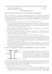
General & technical <strong>Department</strong>s<br />
The electtrroni<br />
ics <strong>of</strong>f ALIICE dimuon ttrracki ing chamberrs<br />
<strong>IPN</strong>O Participation : V. Chambert, P. Courtat, S. Drouet, B.-Y. Ky, J-M. Martin, C. Oziol<br />
Collaboration : Institut de Physique Nucléaire d’Orsay, Saha Institute <strong>of</strong> Nuclear Physics, Istituto<br />
Nazionale di Fisica Nucleare Sezione di Cagliari, Subatech Nantes<br />
L’électronique des chambres à fils du bras Dimuon d’Alice<br />
Le bras Dimuon de l’expérience Alice du Cern comprend entre autres un système de reconstruction de traces des<br />
particules composé de 10 chambres à fils reparties dans 5 stations. L’<strong>IPN</strong>O a en charge la coordination de<br />
l’électronique pour tout le bras Dimuon, ainsi que la construction de la station 1. Le système de lecture des<br />
chambres comprend des cartes frontales de lecture et de numérisation des données, des bus de transmission vers<br />
les châssis CROCUS de lecture et un châssis de transmission et de mise en forme du trigger. Après une brève<br />
présentation de ces systèmes nous décrirons de façon plus détaillée le système CROCUS.<br />
<strong>Electronics</strong> architecture<br />
The ALICE dimuon arm is, for the main parts, composed <strong>of</strong><br />
several absorbers, <strong>of</strong> a trigger system, <strong>of</strong> a dipole and <strong>of</strong> a<br />
tracking system. The tracking system is composed <strong>of</strong> five<br />
stations with two chambers for each <strong>of</strong> them.<br />
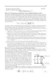
<strong>IPN</strong> Orsay is in charge <strong>of</strong> the electronics coordination for<br />
the tracking system (fig 1). It means that front-end<br />
electronics (≈20 000 Manu boards, more than 10 6 channels),<br />
CROCUS read out crates (≈ 22 crates), trigger dispatching<br />
crates (2 crates) and the related s<strong>of</strong>tware were designed at<br />
Orsay and we will produced for the whole Dimuon<br />
collaboration.<br />
Besides these elements, data bus transmission (bus patch)<br />
were designed at Orsay but each station adapted the system<br />
for its needs and produced them.<br />
Orsay is also responsible for the design and production <strong>of</strong><br />
transmission boards called translators and bridges both for<br />
station 1 and 2.<br />
CROCUS crate<br />
A rough estimation <strong>of</strong> the typical information<br />
number to read in the case <strong>of</strong> a “mean” collision gives<br />
about 150 kB distributed in the five stations. Using a safety<br />
factor <strong>of</strong> 2, the electronics will have to handle an<br />
acquisition rate <strong>of</strong> 1200 evts/s for the lead beams and <strong>of</strong><br />
DETECTOR<br />
FEE<br />
FEE<br />
2 x 32<br />
PADs<br />
PATCH BUS<br />
Up to 26 or 3 x 17<br />
MANU BOARD.<br />
Up to 100 PATCH BUS<br />
per detector.<br />
HIGH VOLTAGE<br />
MANU<br />
SLOW CONTROL<br />
DETECTOR: Chapter 1<br />
FEE: Chapter 2<br />
MANU: Chapter 2.1<br />
READ OUT: Chapter 3<br />
DISPATCHING: Chapter 3.2<br />
CROCUS: Chapter 3.3<br />
SOFTWARE: Chapter 3.4<br />
LOW VOLTAGE: Chapter 4<br />
HIGH VOLTAGE: Chapter 5<br />
SLOW CONTROL: Chapter 6<br />
EMC: Chapter 7<br />
ALICE TRACKING DIMUON SYSTEM:<br />
ELECTRONICS & SOFTWARE<br />
Translator<br />
Board.<br />
LOW VOLTAGE<br />
EMC<br />
10 Meter max<br />
Ribbon cable<br />
READ OUT.<br />
CROCUS Crate<br />
Up to 50 PATCH BUS connected.<br />
FRT<br />
DAQ<br />
Optical link:<br />
DDL<br />
100 meter.<br />
PC<br />
CRT<br />
SOFTWARE<br />
Ribbon cable<br />
40 meter<br />
TCI<br />
One crate for all<br />
CROCUS.<br />
FFT FTD<br />
Link to download:<br />
Pedestals.<br />
DSP code.<br />
From CTP<br />
Trigger information:<br />
L0, L1…..<br />
ETHERNET:<br />
- Monitoring.<br />
- Stand alone DAQ.<br />
- Test configuration.<br />
fig 1:<br />
2000 evts/s for the high intensity Ca beams.<br />
- 142 -<br />
The choice has been done to use DSP AD21160M (Digital<br />
Signal Processor) farms to achieve the data readout coming<br />
from the FEE. These DSPs are gathered in « clusters » in 20<br />
specific crates called CROCUS (Cluster Read Out<br />
Concentrator Unit System). Each crate is composed <strong>of</strong> 5<br />
cards called « frontal » directly connected to the Patch<br />
buses by ribbon cables and <strong>of</strong> a concentrator card which<br />
collects the data coming from all the frontal cards then,<br />
after, formatting, transmits them to the SIU (Source<br />
Interface Unit) which will achieve the transmission towards<br />
the DDL (Detector Data Link) (fig 1). This modularity<br />
provides a high readout speed and minimizes the
General & technical <strong>Department</strong>s<br />
consequences <strong>of</strong> a malfunctioning <strong>of</strong> an element. Moreover,<br />
the use <strong>of</strong> all these DSPs permits the buffering <strong>of</strong> events at<br />
different levels in the readout chain.<br />
Each CROCUS crate has many functions :<br />
- it picks up the detectors data, it concentrates them, it<br />
sends them to the DAQ<br />
- it generates the Front-end control signals and send<br />
them to the front-end through buses<br />
- it picks up trigger signals from dispatching crate and it<br />
broadcasts them to the Front-end electronics<br />
- It generates calibration signals, it sends them to the<br />
detectors, and it processes the calibration data and it<br />
sends them to the DAQ<br />
- It detects failures on the read out chain<br />
The production <strong>of</strong> the 22 crates is foreseen for 2006.<br />
The very complex s<strong>of</strong>tware design is in progress<br />
All the CROCUS crates are close to the detector (less than<br />
10 meters) to insure a good efficiency <strong>of</strong> the data<br />
acquisition through 8 bits/ 20Mo/s linkport. The crate itself<br />
is a specific one VME 6U 9T, amagnetic aluminum made,<br />
very compact to be easily integrated on the detector.<br />
The CROCUS architecture concentrates data with the<br />
following scheme :<br />
- each CROCUS frontal board (CROCUS_FRT) receives<br />
data from 10 buses and it concentrates them within 2<br />
front-end DSP.<br />
- All the front-end DSP (10 for a CROCUS crate) are<br />
connected through the back plane (CROCUS_back) to<br />
2 DSP called concentrators located. Each connection is<br />
done with a linkport.<br />
- The concentrator DSP are located on a concentrator<br />
board called CROCUS_CRT.<br />
- A master DSP located on CROCUS_CRT gathers all<br />
the data via a parallel bus 320MB/s and sends them<br />
through a Xilinx FPGA to the SIU unit<br />
- The SIU unit transmits data to ALICE DAQ with an<br />
optical fiber.<br />
References<br />
Fig 2 : CROCUS crate prototype<br />
CROCUS_FRT, CROCUS_CRT, CROCUS_Back boards<br />
are designed. Their integration in the specific crate is in<br />
progress.<br />
[1] The electronics <strong>of</strong> ALICE dimuon tracking chamber PRR<br />
(2003)<br />
- 143 -
General & technical departments<br />
The ASIIC developmentt actti ivitti<br />
ies <strong>of</strong>f tthe Electtrroni<br />
ics Grroup<br />
<strong>IPN</strong>O Participants : J.-C. Cuzon, S. Drouet, P. Edelbruck, E. Wanlin<br />
Les activités de développements d’ASICS du Service d’Electronique Physique<br />
Les détecteurs développés dans le domaine de la physique nucléaire embarquent aujourd’hui une instrumentation<br />
de plus en plus complexe qui peut parfois comporter plusieurs millions de voies de mesure. Les niveaux de<br />
précision requis, les volumes de données, la complexité des traitements effectués en ligne et les vitesses de<br />
transfert conduisent fréquemment à abandonner les technologies d’électronique traditionnelle (discrète) et à<br />
recourir aux techniques d’intégration sur silicium. Le Service d’Electronique Physique de l’Institut est engagé dans<br />
cette voie depuis de nombreuses années et possède à son actif des réalisations importantes. On peut citer un<br />
circuit de mesure de temps (TDC) destiné à la spectrométrie de masse, une chaîne de mesure pour les détecteurs<br />
au silicium développée en collaboration avec le CEA et dernièrement une mémoire analogique rapide destinée à la<br />
numérisation de signaux à très grandes vitesses. Le savoir-faire acquis par le groupe dans le domaine du<br />
développement d’ASIC est aujourd’hui significatif et les outils informatiques disponibles permettent d’aborder le<br />
développement de circuits analogiques-numériques complexes.<br />
The complexity <strong>of</strong> the electronic equipment embedded in<br />
nuclear physics detectors is becoming quite complex in<br />
terms <strong>of</strong> technical specifications but also in terms <strong>of</strong><br />
channel count. A detector may comprise several millions <strong>of</strong><br />
electronic channels. The required precision level, the<br />
volume <strong>of</strong> data and the complexity <strong>of</strong> the processing<br />
performed online <strong>of</strong>ten leads to move from traditional<br />
discrete technology to integrated solutions. The <strong>Electronics</strong><br />
Group <strong>of</strong> the Institute has started integrating designs many<br />
years ago and several components have been developed.<br />
CRT-C DST-9<br />
I) was instrumented in the early 90’s with discrete<br />
electronics. The second generation detector had several<br />
hundreds <strong>of</strong> channels and clearly required an integrated<br />
solution. A collaboration team was set up between <strong>IPN</strong> and<br />
CEA for the design <strong>of</strong> an ASIC. The aim was to come up<br />
with a chip performing timing and energy measurements<br />
for 16 channels in a single chip (preamplifier, trigger,<br />
shaper, time to analog converter and data read-out). The<br />
preamplifier, the energy section and the logic interfaces<br />
were designed at <strong>IPN</strong> and the timing and the multiplexing<br />
modules at CEA.<br />
The first achievement was a chipset aimed to mass<br />
spectroscopy. The issue at this time (mid 90’s) was more <strong>of</strong><br />
a technical nature. The requirement was to measure time<br />
intervals with a resolution better than 0.25 ns and a very<br />
high repetition rate (multi-hit). Less than 20 ns may have<br />
elapsed between two successive events. These features<br />
were absolutely not achievable with commercial<br />
components and have led to the design <strong>of</strong> two original<br />
ASICs. The development has been performed using a<br />
bipolar technology from the French silicon founder<br />
Thomson. It was a success and the chips have been used in<br />
a wide range <strong>of</strong> instrument during 10 years. They represent<br />
the heart <strong>of</strong> CTN, a module aimed to mass spectroscopy,<br />
now in use in many laboratories worldwide, as well as<br />
COMET, a general purpose acquisition board used at<br />
Tandem and CERN. They have also been implemented in<br />
TOHR, a high resolution instrument for nuclear biology<br />
research and recently in G0, an experiment in hadronic<br />
physics (TJNAF-USA).<br />
MUST<br />
Many experiments in nuclear physics use detectors<br />
sensitive to charged particles. Semi-conductor devices are<br />
very well suited for this purpose and allow for a precise<br />
measurement <strong>of</strong> energy, time and position. Position<br />
measurements are using matrix <strong>of</strong> silicon detectors with<br />
high channel counts. The first detector <strong>of</strong> this kind (MUST<br />
- 144 -<br />
MAR<br />
View <strong>of</strong> the ASIC MAR<br />
Another field rapidly developing in nuclear instrumentation<br />
is the digital pulse shape analysis <strong>of</strong> signals issued by
General & technical departments<br />
detectors <strong>of</strong> many kinds. These techniques can be used for<br />
the localization <strong>of</strong> an interaction within a crystal<br />
(Germanium) and for the mass over charge discrimination<br />
<strong>of</strong> the incoming particle (silicon or scintillators). Off the<br />
shelf fast flash ADCs can be used directly when the signals<br />
are reasonably slow. With faster signals, the analog to<br />
digital conversion cannot be performed directly. One way<br />
to overcome this difficulty is to sample and store the fast<br />
signal in a high speed analog memory (pipeline) and to<br />
“replay” the portion <strong>of</strong> interest at a lower rate, allowing for<br />
the use <strong>of</strong> a conventional flash ADC. The technique is<br />
called FISO (Fast In - Slow Out). Although such methods<br />
are now well known, no component is available on the<br />
market place. The technique is clearly relevant for the<br />
AZ4π R&D program and the design <strong>of</strong> such an analog<br />
pipeline was decided.<br />
The recording device is composed <strong>of</strong> a matrix <strong>of</strong> 1240<br />
analog storage cells. Each cell is written in turn, with a time<br />
interval <strong>of</strong> 0.5 ns. The matrix is handled as a ring buffer,<br />
i.e. writing is performed continuously, overwriting the<br />
older cells, until the process is stopped by a trigger signal.<br />
The content is then frozen and the stored voltages can be<br />
read out through a read bus.<br />
successfully tested. 25 units have been packaged and will<br />
been used to build up a first set <strong>of</strong> prototype boards for the<br />
actual detector. However, a few flaws have been detected<br />
and corrections will be performed. A new prototype will be<br />
submitted to the founder at the beginning <strong>of</strong> 2006<br />
The fast amplifier<br />
Several building blocks had to be especially designed for<br />
this application:<br />
- The storage cell itself, composed <strong>of</strong> a capacitor<br />
associated to very accurate switching devices<br />
- The delay-locked-loop, an element delivering the 0.5<br />
ns time interval<br />
- The read and write amplifiers, with a bandwidth as<br />
large as 350 MHz and high slew rate<br />
- The logic <strong>of</strong> the whole system.<br />
The building blocks were designed in such a way that they<br />
can be reused later, even for a different application.<br />
Furthermore, two <strong>of</strong> them were made available to the entire<br />
<strong>IN2P3</strong> community through the special “club 035” structure<br />
started in 2004.<br />
The amplifier test chip<br />
Perspectives<br />
The delay-locked-loop<br />
The blocks were first manufactured as single elements in<br />
special test chips and tested. The entire design has then<br />
been assembled and the complete chip manufactured<br />
beginning <strong>of</strong> 2005. The circuit was functional and has been<br />
The <strong>Department</strong> <strong>of</strong> <strong>Electronics</strong> has now built up a valuable<br />
experience in ASIC design. Skilled engineers doted with<br />
powerful CAD tools are available within the Institute.<br />
Numerous physics project can and will use these techniques<br />
in the future. They will benefits in both the increase <strong>of</strong> the<br />
performance level (precision, energy and timing<br />
resolutions) and the complexity level : complex signal<br />
processing over millions <strong>of</strong> channels.<br />
- 145 -
General & technical departments<br />
MAR :: An asic fforr tthe ffastt digittal<br />
lizatti<br />
ion <strong>of</strong>f currrrentt signals<br />
<strong>IPN</strong>O Participation : J.-C. Cuzon, S. Drouet, P. Edelbrück, L. Leterrier, E. Wanlin<br />
MAR : un asic pour la numérisation rapide des signaux de courant<br />
Développé il a 4 ans, le préamplificateur à grande vitesse PACI <strong>of</strong>fre une image précise du processus de collection<br />
de charge d'un détecteur de silicium. Ce signal peut être employé pour la discrimination en Masse/Energie dans ce<br />
type détecteur, en utilisant des techniques de filtrages numériques. Comme aucun composant du commerce ne<br />
s’adapte à nos contraintes, nous avons décidé de concevoir un circuit intégré (asic) d’une mémoire analogique<br />
(MAR) qui échantillonne le signal à très grande vitesse (jusqu'à 2 GSPS) avec la possibilité d’être lue à une vitesse<br />
inférieure (50 MSPS) en employant un ADC du commerce. La pr<strong>of</strong>ondeur de stockage de cette mémoire est<br />
d’environ 1240 échantillons, avec une vitesse d'écriture réglable (de 100MSPS jusqu’à 2GSPS). Après l’étape de la<br />
conception et du dessin physique, le layout a été envoyé chez le fondeur (AMS) en décembre 2004 et nous avons<br />
reçu 25 puces encapsulées en mars 2005. Actuellement nous sommes en train de tester les performances et<br />
fonctionnalités de cet asic MAR dans le but de réaliser une carte d’acquisition rapide.<br />
Introduction<br />
Four years ago, the <strong>Electronics</strong> group developed a new<br />
version <strong>of</strong> charge preamplifier called PACI having an<br />
additional output <strong>of</strong> which the signal is a faithful<br />
representation <strong>of</strong> the current pulse. The knowledge <strong>of</strong> the<br />
shape <strong>of</strong> this pulse makes possible to obtain additional<br />
information (A, Z...) in order to improve discrimination.<br />
Accordingly, the electronics group is designing and<br />
realizing a fast acquisition system allowing to digitalize the<br />
output current signal <strong>of</strong> a preamplifier PACI. These current<br />
signals have the following time characteristics: minimum<br />
rise time <strong>of</strong> 2-3ns, duration <strong>of</strong> the impulse <strong>of</strong> few 10ns to<br />
100ns.<br />
Considering the minimum rise time, the digitalization<br />
system must be very fast, more than 1GSPS (giga samples<br />
per second). Knowing that the very fast converters (><br />
1GSPS) available in the market do not correspond to our<br />
application (too high dissipation, high price, 8 bits <strong>of</strong><br />
resolution), the SEP decided to develop a ASIC which<br />
memorize the current signal at 2GSPS in an analog way.<br />
on one <strong>of</strong> the DLL, this one is lower than 10ps rms. The<br />
average value <strong>of</strong> one delay is 502ps.<br />
When the analog levels <strong>of</strong> input current signal are<br />
memorized in the asic, all the samples are sent to an analogto-digital<br />
converter with a sampling frequency <strong>of</strong> 50MSPS<br />
and with 12bits resolution. The digitized samples are then<br />
processed by a FPGA realizing a digital processing <strong>of</strong> the<br />
data.<br />
The diagram below represents the test bench which permits<br />
to characterize the MAR asic.<br />
Presentation <strong>of</strong> the asic MAR<br />
This ASIC called MAR (Fast Analog Memory = Mémoire<br />
Analogique Rapide) is based on an analog pipeline structure<br />
storing the samples in an analog circular buffer. The aim <strong>of</strong><br />
this memory is to memorize in an analog way the current<br />
signal coming from the detector via the PACI preamplifier.<br />
This analog signal is sampled at 500ps (2GSPS) by the<br />
1239 memorizing cells made <strong>of</strong> capacitors and MOS<br />
switches. Thus, this memory can store a 619.5ns signal<br />
when the time base is 500ps.<br />
In the asic, the 1239 cells are placed in matrix form : 59<br />
lines by 21 columns. Thus, each line contains 21 memory<br />
cells. This dimension was not taken randomly : thanks to<br />
this one, the asic can sample the signal with various time<br />
Fig. 2 : Photo <strong>of</strong> the test bench with the asic MAR<br />
bases without having time distortion. The following time<br />
bases are available : 500ps, 1ns, 2ns, 5ns and 10ns.<br />
Features <strong>of</strong> the asic MAR<br />
It is important to note that each line is made up <strong>of</strong> 21 • Built in 0.35µm CMOS technology by AMS<br />
memory cells and a DLL (Delay Locked Loop). These 59 • Area : 23mm²<br />
DLLs give all the precision <strong>of</strong> the moment <strong>of</strong> sampling. On • Supply voltage : 3.3V ; Power : 800mW<br />
the first version <strong>of</strong> the asic, jitter measurements were made • Input span : 2Vpp<br />
- 146 -<br />
C DET<br />
C F<br />
PACI<br />
Sortie<br />
courant<br />
Sortie<br />
énergie<br />
Trig<br />
Mémoire<br />
Analogique<br />
Rapide<br />
ASIC "MAR"<br />
Convertisseur<br />
Analogique-Numérique<br />
50MHz / 12bits<br />
Contrôleur<br />
d'Acquisition<br />
Mémorisation<br />
Données<br />
Gestion USB<br />
Carte d'acquisition commandée par un module USB<br />
USB<br />
Traitement<br />
Données<br />
Visualisation<br />
Fig. 1 : Functional diagram <strong>of</strong> the test bench <strong>of</strong> the asic<br />
PC
General & technical departments<br />
• Input bandwidth : 350MHz<br />
• Expected S/N ratio: 72dB<br />
• Programmable time bases (in GSPS) : 2, 1, 0.5,<br />
0.2, 0.1<br />
• 1239 memory cells (matrix <strong>of</strong> 21x59 cells)<br />
• Memory depth : from 619.5ns to 12.39µs (in<br />
function <strong>of</strong> the selected time base)<br />
• Read time (Sending <strong>of</strong> all the analog samples to<br />
the ADC) : 25µs<br />
Asic status<br />
All the analog part <strong>of</strong> this ASIC was designed, simulated,<br />
optimized and drawing by the SEP.<br />
All the digital part allowing the control <strong>of</strong> the analog<br />
pipeline was designed by the SEP and the layout (drawing)<br />
was made at Strasbourg thanks to the help <strong>of</strong> A. Himmi<br />
(Laboratory IReS/<strong>IN2P3</strong>).<br />
The first version <strong>of</strong> the asic was sent to the AMS foundry at<br />
the beginning <strong>of</strong> December 2004, and we received 25 chips<br />
in the middle <strong>of</strong> march 2005.<br />
The design and the realization <strong>of</strong> the asic test bench was<br />
performed in parallel with the foundry <strong>of</strong> the asic.<br />
For few weeks, the SEP has tested the asic (cf. Fig.2), and<br />
for a first prototype, good results appeared. Below, we can<br />
see some sampling results (made by MAR):<br />
Fig. 3 : Sinusoidal signal with a 20MHz frequency and an<br />
amplitude 800mVpp<br />
Some mistakes appeared during the test. Thus, some<br />
correction <strong>of</strong> the layout will be done, and a new version <strong>of</strong><br />
the asic will be sent to the AMS foundry in the first quarter<br />
<strong>of</strong> 2006. So, the new version will be tested in mid-2006.<br />
It is important to note that the first version <strong>of</strong> the asic<br />
MAR works and thus, we will use it in a demonstration<br />
board for AZ4π experiment despite its imperfections.<br />
Future objective<br />
The final goal is to realize a fast acquisition board :<br />
C DET<br />
C F<br />
PACI<br />
Current<br />
Output<br />
Charge<br />
Output<br />
Analog-to-Digital<br />
Converter<br />
Fast Analog<br />
Memory<br />
MAR<br />
AD9235<br />
Sampling Board<br />
Acquisition controller<br />
+<br />
Data storage<br />
+<br />
Communication controller<br />
FPGA and DSP<br />
Analog-to-Digital<br />
Converter<br />
AD9235<br />
Fig. 5: Acquisition board for AZ4π<br />
GBit Link to<br />
DAQ<br />
Trigger<br />
&<br />
Timing<br />
This board will meet the following characteristics :<br />
‣ Compactness (a few cm²) for the integration close to<br />
the detectors (a few thousands channels must be<br />
equipped).<br />
‣ low thermal dissipation.<br />
‣ Modularity.<br />
‣ One energy channel.<br />
‣ One channel for the process <strong>of</strong> the current signal<br />
(shape analysis).<br />
So, the first objective is to correct the layout for the second<br />
version <strong>of</strong> MAR (mid-2006).<br />
The second objective is to realize a fast acquisition system<br />
for the AZ4π R&D program, with the collaboration <strong>of</strong> LPC<br />
Caen and INFN Florence. This system will integrate, <strong>of</strong><br />
course, the asic "MAR", and will be able to do recognitions<br />
<strong>of</strong> the current signals coming from the preamplifier PACI.<br />
For the first version <strong>of</strong> this system, we will use the first<br />
version <strong>of</strong> the asic MAR. The first version <strong>of</strong> this board will<br />
be available in the beginning <strong>of</strong> 2006.<br />
Fig. 4 : Sinusoidal signal with a 100MHz frequency and an<br />
amplitude 650mVpp<br />
- 147 -
General & technical department<br />
The Frrontt End Electtrroni<br />
ics <strong>of</strong>f tthe AGATA dettecttorr<br />
<strong>IPN</strong>O Participation : P. Edelbruck, X. Grave, C. Huss, C. Oziol, S. Royer.<br />
Collaboration : CCLRC, CSNSM, INFN, IReS.<br />
L’électronique de Front-End du détecteur AGATA<br />
AGATA est un spectromètre gamma destiné aux expériences de physique des noyaux exotiques. Il comprend 180<br />
cristaux de germanium de gros volume fonctionnant à basse température. Chaque cristal est segmenté en 36<br />
sections dont les électrodes sont lues par des préamplificateurs à faible bruit embarqués. Ce détecteur apportera,<br />
par rapport à ses prédécesseurs une grande amélioration en efficacité (zones mortes réduites) et en résolution. Il<br />
bénéficiera, au niveau de son électronique de deux innovations techniques majeures : un traitement entièrement<br />
numérique des signaux, associé à une méthode de localisation des interactions basée sur l’analyse des impulsions<br />
de collection de charge. Chacune des 7000 voies d’électronique sera munie d’un convertisseur Analogique-<br />
Numérique à grande vitesse et grande résolution (Flash ADC) associé à une électronique d’acquisition fortement<br />
intégrée. C’est cette électronique qui est en cours de développement à l’<strong>IPN</strong>, en collaboration étroite avec le<br />
CSNSM voisin. Ce dernier fournira les cartes de traitement de premier niveau (1250 unités) et l’<strong>IPN</strong> l’infrastructure<br />
bâtie sur le nouveau standard de télécommunication ATCA (360 cartes portées par 30 châssis).<br />
AGATA is a gamma ray detector aimed to high resolution γ<br />
-ray spectroscopy with exotic beams. Despite its large size,<br />
it is designed to be “portable” and will be used in several<br />
nuclear physics facilities in Europe. The detector is made <strong>of</strong><br />
180 crystals <strong>of</strong> high purity germanium. Each crystal is<br />
segmented into 36 volumes, each <strong>of</strong> which bearing one<br />
electrode, also called segment, read by a high resolution<br />
preamplifier. The detector will provide significant<br />
improvements over its predecessors in terms <strong>of</strong> efficiency<br />
(reduced dead zones) and resolution. It will benefit from<br />
two major technical innovations: all signal processing will<br />
be entirely digital and new localisation algorithms will be<br />
performed on the charge signals, allowing for<br />
unprecedented spatial precision. To achieve these goals,<br />
each <strong>of</strong> the 7000 channels will be read out by a high speed<br />
analog to digital converter associated to a strongly<br />
integrated digital electronics. This electronics is currently<br />
being developed between <strong>IPN</strong> and the neighbour lab<br />
CSNSM. The later is providing the first level local level<br />
mezzanine boards (1250 units) while <strong>IPN</strong> is designing the<br />
infrastructure, based on the new ATCA telecom standard<br />
(360 boards located in 30 crates).<br />
Computing Architecture. This is a new hardware standard<br />
originally designed for telecommunication systems,<br />
featuring very high bandwidth (potentially hundreds <strong>of</strong><br />
Gbyte/s). One crate can accommodate up to 16 large<br />
boards, with a form factor well suited to carry the projected<br />
pre-processing modules. Communication between the<br />
chassis and the external world is performed by one or two<br />
switching boards locally connected to the carriers through<br />
high speed serial links located on the backplane. One single<br />
link <strong>of</strong>fers up to 10 Gbit/s <strong>of</strong> data rate. The actual<br />
communication protocol is not defined by the standard and<br />
remains open for a future choice. The first demonstrator<br />
will use the well known Gigabit Ethernet standard while the<br />
final version will use PCI-express or Infiniband <strong>of</strong>fering<br />
even more bandwidth.<br />
14U<br />
1,5U<br />
8U<br />
3 X 2 Carriers =<br />
1 cluster<br />
15<br />
13<br />
11 9 7 5 3<br />
1<br />
2<br />
3 X 2 Carriers =<br />
1 cluster<br />
4<br />
6 8 10 12 14 16<br />
SWITCH<br />
GbE<br />
ou<br />
PCIexpress<br />
CPU<br />
(option)<br />
1 2 3 4 5 6 7 8 9 10 11 12 13 14 15 16<br />
The 36 fold segmented germanium crystal<br />
The ATCA standard<br />
The AGATA throughput is currently estimated to 380<br />
Mbyte/s per crystal i.e. 2.2 Gbyte/s for the 6 crystal filling<br />
in one crate. A breakthrough was really required to cope<br />
with such a data rate. The solution was found with ATCA.<br />
The acronym stands for Advanced Telecommunications<br />
- 148 -<br />
4,5U<br />
23’’<br />
One chassis bearing the electronics <strong>of</strong> 6 crystals<br />
System architecture<br />
The signals issued by the crystals are first digitized in the<br />
vicinity <strong>of</strong> the detectors by an ensemble <strong>of</strong> ADC (14 bit -<br />
100 Msample/s) developed by IReS in Strasbourg. The high<br />
speed digital stream is transported to the local level
General & technical department<br />
processing electronics through optical fibres at the rate <strong>of</strong> 2<br />
Gbit/s. One set <strong>of</strong> fibres is handling 6 electrodes, 6 sets<br />
being required for one crystal, plus one for the central<br />
contact. Each fibre feeds one mezzanine card where the<br />
digital stream is rebuilt for processing using high speed<br />
deserializers (SERDES). Field Programmable Gate Arrays<br />
(FPGA) perform in real time the calculation <strong>of</strong> the energy<br />
<strong>of</strong> physical events (digital shaping) and the recording <strong>of</strong> the<br />
signal shape, just like a digital oscilloscope. Another type<br />
<strong>of</strong> mezzanine board (Global Trigger System) designed in<br />
Padova (INFN) provides an accurate clock to the whole<br />
system. It also delivers the “date” <strong>of</strong> all physical events<br />
with a resolution <strong>of</strong> 10 ns (Time Stamping).<br />
1 crystal<br />
6 Segments<br />
Digitiser<br />
6 Segments<br />
Digitiser<br />
Core<br />
Digitiser<br />
6 Segments<br />
Digitiser<br />
6 Segments<br />
Digitiser<br />
6 Segments<br />
Digitiser<br />
6 Segments<br />
Digitiser<br />
Central<br />
trigger<br />
GTS<br />
CORE<br />
SEG<br />
SEG<br />
SEG<br />
SEG<br />
SEG<br />
SEG<br />
ATCA<br />
DAC<br />
ATCA<br />
DAC<br />
Master<br />
Slave<br />
The electronics <strong>of</strong> one crystal<br />
Slow<br />
control<br />
PSA<br />
Or PrePSA<br />
Power<br />
management<br />
The pre-processing boards<br />
The pre-processing boards are built around state <strong>of</strong> the art<br />
FPGA <strong>of</strong> the Virtex-II pro family. Two chips are required<br />
for six channels. Each chip bears the deserialsers, one<br />
power-PC processor and several millions <strong>of</strong> programmable<br />
logic gates performing all the digital processing in real<br />
time. The boards communicate with the central control<br />
system through Ethernet links taken over from the carrier<br />
boards.<br />
Data acquisition<br />
Clock<br />
TCLK port<br />
Slow control<br />
OSC LOC<br />
CY<br />
2DP3120<br />
The carrier boards<br />
JTAG connect.<br />
JTAG<br />
JTAG<br />
SWITCH<br />
AS91L1006<br />
FPGA<br />
TCLK OSC LOC<br />
RevMII<br />
JTAG<br />
32 bits 100Mhz<br />
CPU TRACE<br />
LSA connect.<br />
JTAG<br />
FIFO<br />
CPU serial<br />
EEPROM<br />
Config CPU<br />
Switch<br />
10/100<br />
ZL50407<br />
DATA<br />
FIFO Acquisition<br />
FPGA<br />
FIFO Carrier<br />
XC2VP40/50<br />
FIFO<br />
JTAG<br />
CTRL<br />
AS91L1001<br />
The carrier board<br />
32 bits<br />
CPU<br />
SRAM<br />
256Ko<br />
OSC LOC<br />
RevMII<br />
32 bits<br />
100ME Base<br />
PHY Fabric<br />
MII<br />
C<br />
P<br />
U<br />
MOBILE<br />
SDRAM<br />
128Mo<br />
Micron<br />
selectMap<br />
EEPROM<br />
Config<br />
JTAG DAFC<br />
TCLK PORT<br />
HUB1<br />
HUB2<br />
PCI Express<br />
ou GbE<br />
I2C thermal<br />
And power<br />
control<br />
POWER<br />
3.3V 2.5V<br />
1,2V 1.5V 1.8V<br />
The role <strong>of</strong> the carrier boards is to provide an infrastructure<br />
to the processing mezzanine cards. Each detector will<br />
necessitate two carriers holding six segment mezzanines,<br />
one central contact mezzanine and one GTS card. The first<br />
facility <strong>of</strong>fered by the carrier is <strong>of</strong> a mechanical nature. One<br />
carrier card will house four mezzanines built in the<br />
standard PMC form factor. The connexions to the detectors,<br />
to the ADC system and to the central trigger will be<br />
performed through the front panel with optic fibre<br />
connectors. The carrier board will also generate the<br />
voltages required by the various components. Up to 200 W<br />
<strong>of</strong> power will be converted into 6 different low voltages<br />
from the unique 48 V source provided by the ATCA<br />
backplane.<br />
Two large FPGA will handle the data acquisition process<br />
itself. Synchronisation signals will be received from the<br />
GTS board and distributed to all mezzanines. Trigger<br />
requests will be gathered from the central contact and sent<br />
to GTS. Trigger commands will then be dispatched to all<br />
cards. When the reading process is completed on each<br />
mezzanine (energy calculation, signal storage etc.) the<br />
carrier board will collect the data from all modules, build<br />
the event package and send it to the central DAQ through<br />
the backplane and the switch boards.<br />
Last but not least, the carrier will handle all the “slow<br />
control” issues, ranging from basic house keeping like<br />
power and temperature management, s<strong>of</strong>tware download, to<br />
physics parameter handling and online calibration<br />
procedures. As the total number <strong>of</strong> FPGA in the system<br />
will be very high (several thousands), all possible<br />
maintenance operation like updating the hardware codes<br />
(VHDL) will be feasible from the remote central control<br />
system without any manual intervention on the boards. All<br />
slow control communication will be performed through<br />
standard Ethernet links using the TCP/IP protocol, making<br />
remote control versatile and portable.<br />
Pulse shape analysis<br />
The 30 ATCA chassis will communicate with a large<br />
processor farm which will perform the in-line analysis <strong>of</strong><br />
all the channels in order to extract two important data :<br />
- The geometrical location <strong>of</strong> the interaction within the<br />
crystal. This information will permit a precise<br />
correction <strong>of</strong> the Doppler Effect affecting the energy<br />
measurement, leading to a resolution improvement <strong>of</strong><br />
an order <strong>of</strong> magnitude over existing detectors.<br />
- In the case <strong>of</strong> a Compton cascade, determine the<br />
position <strong>of</strong> each photon belonging to the event and<br />
calculate the total energy as well as the angle <strong>of</strong> the<br />
original photon.<br />
The next future<br />
Building and testing the electronics will take three steps :<br />
one single detector will be equipped and tested mid 2006 in<br />
Orsay. A demonstrator made <strong>of</strong> a large set <strong>of</strong> 15 detectors<br />
will then be constructed and used for real physics<br />
experiments in 2007. The complete detector with 180<br />
crystals will be ready by 2010.<br />
- 149 -
General & technical departments<br />
Electtrroni<br />
ics fforr MUST2 ((MUrr à Sttrri ip))<br />
<strong>IPN</strong>O Participation : J.-P. Baronick, D. Beaumel, P. Edelbruck, G. Guerin, P. Guilland, D. Lalande, L.<br />
Lavergne, L. Leterrier, V. Le Ven, A. Mongaillard, D. Rougier, S. Royer, S. Tanguy, M. Vilmay, E. Wanlin<br />
Collaboration : GANIL, CEA/DAPNIA.<br />
MUST2 est un télescope ∆E-E de seconde génération constitué d’un détecteur Si à 256 pistes double face suivi de<br />
deux détecteurs Si(Li) segmentés en 8 secteurs et de seize cristaux de CsI. Les détecteurs, l’électronique front end<br />
et la mécanique ont été pris en charge par le service détecteurs de la DR, le SEP et le SRM. L’électronique front<br />
end est réalisée autour d’un composant intégré full custom (MATE3), conçu en collaboration avec le CEA/DAPNIA.<br />
Pour l’électronique d’acquisition, elle a été conçue par le GANIL en standard VXI taille C. Actuellement, la<br />
production d’un ensemble de quatre télescopes est lancée et sera achevée en janvier 2006. Le reste de la<br />
production sera réalisé courant 2006. Les premières résolutions en énergies obtenues avec le détecteur Si à strips<br />
sont de l’ordre de 40keV avec une source alpha 3 pics et de 30keV au générateur d’impulsion.<br />
MUST II is a charged particle detector <strong>of</strong> second generation<br />
developed in collaboration with GANIL, CEA/DAPNIA<br />
and <strong>IPN</strong>. Each telescope (Fig 1) consists <strong>of</strong> a double-sided<br />
Silicon strips (Si strips) detector, followed by two Silicon<br />
Lithium (Si(Li)) detectors and sixteen Caesium Iodide (CsI)<br />
scintillators with photodiode read-out. The Si strips detector<br />
has128 strips on each side and the expected energy and time<br />
resolution are 50keV and 250ps for 5.48MeV alpha. Each<br />
Si(Li) detector is divided into 8 segments with the 120keV<br />
desired energy resolution. For the CsI, the requested energy<br />
resolution is 5% for 5.48MeV alpha.<br />
All mechanics has been designed by SRM. In particular,<br />
this mechanics is composed <strong>of</strong> the cooling system allowing<br />
to drain the heat <strong>of</strong> electronic devices <strong>of</strong> outside the vacuum<br />
chamber in order to hold a constant low temperature.<br />
Si (Li)<br />
Si (Strips)<br />
CsI<br />
Kapton<br />
Front end electronics<br />
The front end electronics, realized by SEP, is located close<br />
to the rear <strong>of</strong> each telescope and consists <strong>of</strong> two electronic<br />
boards called MUFEEX3 (MUst Front End <strong>Electronics</strong>) and<br />
MUFEEY3. The links between Si strips detectors and<br />
electronic boards are made via Kapton flexible circuits.<br />
Above, the top and bottom views <strong>of</strong> the MUFEEX3 board<br />
processing 128 signals from the junction side <strong>of</strong> Si strips<br />
detector, as well as the 16 channels <strong>of</strong> the Si(Li) detectors.<br />
MUFEEX3 and MUFEEY3 boards are nearly the same.<br />
Apart from MUFEEY3 which processes 128 signals from<br />
the ohmic side <strong>of</strong> Si strips detector and 16 channels from<br />
photodiodes.<br />
Each MUFEE bears 9 MATE3 ASICs (Application Specific<br />
Integrated Circuits), each processing 16 channels in energy<br />
and time. These energy and time information are carried on<br />
2 analogue lines per board, read in current differential mode<br />
through twisted pair to the external VXI crate. The MATE3<br />
are connected in daisy chain and read one after the other.<br />
The readout time for 544 information is 80µs.<br />
In order to have a good immunity against the<br />
electromagnetic perturbations, all readout signals are<br />
transmitted in LVDS (Low Voltage Differential Signal).<br />
The slow control, assured via the I²C industrial protocol,<br />
allows in particular the configuration <strong>of</strong> the ASICs, the<br />
temperature monitoring, the test signal injection, the<br />
multiplexing <strong>of</strong> inspection channels, the board<br />
identification and the memorization <strong>of</strong> experiment<br />
parameters.<br />
On each MUFEE, one pulse generator drive each analogue<br />
test input <strong>of</strong> each MATE3, which allows to check the good<br />
functionality <strong>of</strong> all ASICs and to calibrate electronics<br />
channel.<br />
MATE3 (Must Asic for Time and Energy)<br />
It has been realized in collaboration with the CEA/DAPNIA<br />
from Saclay : SEP has developed the charge sensitive<br />
preamplifier, the energy channel and the logic I2C<br />
interface; CEA has taken responsibility for the timing<br />
energy and other blocks explained later and for the final<br />
assembly. The ASIC technology is the 0.8μm BICMOS<br />
from AMS. MATE3 has 16 channels and delivers three<br />
types <strong>of</strong> analogue information for each channel: time <strong>of</strong><br />
flight and energy loss <strong>of</strong> the detected particle and value <strong>of</strong><br />
DC leakage current. MATE3 also gives a trigger logic<br />
signal corresponding to the cross over <strong>of</strong> an adjustable<br />
threshold. The slow control <strong>of</strong> the ASIC is assured via the<br />
I2C industrial protocol.<br />
- 150 -
General & technical departments<br />
Architecture<br />
The block diagram <strong>of</strong> one MATE channel is shown<br />
hereafter:<br />
ini<br />
idf<br />
idf<br />
ininj<br />
cf1<br />
Idf<br />
CSA<br />
cf0<br />
¼Cf<br />
Rf<br />
selFiltre<br />
1us/3us<br />
Filtre & Ampli<br />
Filtre &<br />
Ampli<br />
hold<br />
Track&Hold<br />
TEMPS<br />
+ discri - TAC<br />
resetCSA seuils<br />
requêtei stop<br />
DAC 8 bits<br />
Requete j<br />
Canali<br />
REQUÊTE<br />
VIC<br />
DATA<br />
One channel consists in three main blocks : A charge<br />
sensitive preamplifier, the energy block, and the time and<br />
decision block.<br />
MATE3 must be able to accept current signals coming not<br />
only from both sides <strong>of</strong> the Si strip detector, but also from<br />
SiLi and CsI detectors. This means that each channel can<br />
process both signal polarities, from the charge sensitive<br />
preamplifier to the energy and time blocks. Furthermore,<br />
the charge sensitive preamplifier gain and the filter peaking<br />
time are programmable to suit various kind <strong>of</strong> detectors and<br />
particles.<br />
Charge sensitive preamplifier<br />
The architecture is a single ended folded cascade amplifier,<br />
bipolar, using MOS and bipolar transistors. The input<br />
transistor is a wide PMOS <strong>of</strong> 8500μm/1.2μm<br />
(gm=28.4mS). The rise time <strong>of</strong> the preamplifier is 10ns.<br />
A set <strong>of</strong> four integration capacitors programmable via two<br />
slow control bits is used to match the desired gain<br />
according to the selected detector.<br />
The maximum energies to be accepted by the charge<br />
sensitive preamplifier and energy block are +/-45MeV,<br />
225MeV and 200MeV for the Si strips, SiLi and CsI<br />
detectors respectively.<br />
Energy channel<br />
This block is composed <strong>of</strong> a shaper and a track and hold.<br />
The shaper consists <strong>of</strong> a CR-RC filter, with respectively 1<br />
and 3μs <strong>of</strong> peaking time, selectable by slow control, for the<br />
Si strips and SiLi/CsI detectors.<br />
Then, the amplitude <strong>of</strong> the signal is memorized via a track<br />
and hold stage on the rise time <strong>of</strong> the HOLD signal coming<br />
from MUVI. In read out mode, this memorized signal is<br />
sent to a Voltage to Current Converter (VIC) whose transfer<br />
gain is +/-2mA/V.<br />
Timing and decision channel<br />
This channel has two main objectives : determine quickly<br />
whether the channel has triggered or not and measure the<br />
time <strong>of</strong> flight <strong>of</strong> the particle.<br />
The first section is a fast CR 2 -RC filter with a peaking time<br />
<strong>of</strong> 22ns; it has a differential structure, thus providing<br />
immunity against parasitic coupling and reducing jitter to<br />
achieve a good time resolution. The differential outputs <strong>of</strong><br />
this shaper, then, pass through a leading edge discriminator,<br />
OU<br />
x16<br />
ENERGIE<br />
COURANT<br />
in which the threshold voltage is set by an internal 8 bits<br />
programmable DAC.<br />
The discriminator output gives the start signal to the time to<br />
amplitude converter (TAC) as well as the « REQUETE »<br />
signal which is ‘or wired’ with the other fifteen channels <strong>of</strong><br />
MATE3. The intrinsic time resolution <strong>of</strong> the TAC is 18ps<br />
FWHM. The TAC is stopped by an external signal “STOP”<br />
coming from MUVI.<br />
In read out mode, the time information is sent to a Voltage<br />
to Current Converter.<br />
The TAC has two programmable time ranges: 0ns/300ns<br />
and 0ns/600ns.<br />
Power consumption, layout and package<br />
The power consumption <strong>of</strong> the chip is 447mW. The layout<br />
is shown hereafter; the area is 41mm2<br />
(6.438*6mm.368mm). MATE is packaged in a ceramic 64<br />
pins TQFP64L.<br />
Inpac1<br />
Inpac16<br />
Complete telescope system<br />
The GANIL developed a VXI-C standard board, called<br />
MUVI (MUst in VXI), assuring the slow control, data<br />
coding, digital processing and data memorization for four<br />
telescopes. The management <strong>of</strong> trigger signals is performed<br />
by the GMT module.<br />
The communication between MUFEE and MUVI boards is<br />
carried in the eight meters transmission line.<br />
The ensemble <strong>of</strong> front end electronics is supplied by several<br />
CAEN power supply modules located in SY1527 system.<br />
Châssis VXI<br />
MUVI (VXI taille C)<br />
Mémorisation<br />
&<br />
Traitement<br />
&<br />
contrôle<br />
host<br />
Interface VXI<br />
Mise en forme<br />
4 bus analog<br />
& codage<br />
Signaux cont<br />
Slow control<br />
Bus I2C<br />
Trigger local<br />
Trigger externe<br />
GMT<br />
1 bus analog<br />
bus I2C 1 bus analog<br />
signaux cont.<br />
1 MATE2<br />
8 MATE2<br />
MUFEE Y<br />
INTERCSI<br />
128 strips en Y<br />
16 pads<br />
128 strips en X<br />
8 MATE2 1 MATE2<br />
1 bus analog<br />
signaux cont. bus I2C 1 bus analog<br />
Détecteur Si strips<br />
Détecteur Si(Li)<br />
16 pads<br />
Détecteur CsI<br />
MUFEE X<br />
- 151 -