EQ Station Manual v. 2.01 sw. 220 English - TC Electronic
EQ Station Manual v. 2.01 sw. 220 English - TC Electronic EQ Station Manual v. 2.01 sw. 220 English - TC Electronic
GLOBAL VIEW Basic Operation • Press GLOBAL to access the Global View - Cluster overview page. Use the CHANNEL wheel to scroll through channels and view channel settings. • Select I/O Settings or Channel Config. depending on which settings you wish to edit and press OK. • Select parameter/field to edit using the CURSOR keys and set value using the ADJUST wheel. Exit Place cursor here and press OK to exit the Global page. Meters One or two Output meters depending on whether single or paired channels are selected. Cluster position Indicates which position in the Cluster the selected Input channel is routed to. Status LED Green indicates : No conflicts. Red indicates : Possible conflict. Two Input Channels may be assigned to the same Cluster position. Channel Use the CHANNEL wheel to select which Cluster position you wish to see status on. Device Name Shows the name of the selected device. The Device name is set on the Setup page on each device. Channel Icon To each channel an icon can be assigned giving fast visual identification of which channel is operated. E.g. a microphone to a vocal channel, a guitar for the guitar channel etc. Input Indicates which Input channel is routed to the selected cluster position. Pair Channels can be paired as 1/2, 3/4, 5/6 - 63/64. Channel Name Though an Icon assigned to each channel creates a basic overview, you can of course assign a specific name to each channel too. Preset Name The preset name is created when you store the preset. Auto Setup Press to perform an auto assignment of all available channels. - see description on page 6-7. 18
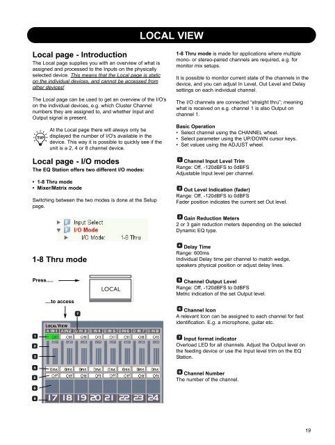
LOCAL VIEW Local page - Introduction The Local page supplies you with an overview of what is assigned and processed to the Inputs on the physically selected device. This means that the Local page is static on the individual devices, and cannot be accessed from other devices! The Local page can be used to get an overview of the I/O's on the individual devices, e.g. which Cluster Channel numbers they are assigned to, and whether Input and Output signal is present. At the Local page there will always only be displayed the number of I/O's available in the device. This way it is possible to quickly see if the unit is a 2, 4 or 8 channel device. Local page - I/O modes The EQ Station offers two different I/O modes: • 1-8 Thru mode • Mixer/Matrix mode Switching between the two modes is done at the Setup page. 1-8 Thru mode is made for applications where multiple mono- or stereo-paired channels are required, e.g. for monitor mix setups. It is possible to monitor current state of the channels in the device, and you can adjust In Level, Out Level and Delay settings on each individual channel. The I/O channels are connected “straight thru”; meaning what is received on e.g. channel 1 is also Output on channel 1. Basic Operation • Select channel using the CHANNEL wheel. • Select parameter using the UP/DOWN cursor keys. • Set values using the ADJUST wheel. Channel Input Level Trim Range: Off, -120dBFS to 0dBFS Adjustable Input level per channel. Out Level Indication (fader) Range: Off, -120dBFS to 0dBFS Fader position indicates the current set Out level. Gain Reduction Meters 2 or 3 gain reduction meters depending on the selected Dynamic EQ type. 1-8 Thru mode Delay Time Range: 600ms Individual Delay time per channel to match wedge, speakers physical position or adjust delay lines. Press..... ....to access Channel Output Level Range: Off, -120dBFS to 0dBFS Metric indication of the set Output level. Channel Icon A relevant Icon can be assigned to each channel for fast identification. E.g. a microphone, guitar etc. Input format indicator Overload LED for all channels. Adjust the Output level on the feeding device or use the Input level trim on the EQ Station. Channel Number The number of the channel. 19
- Page 3 and 4: IMPORTANT SAFETY INSTRUCTIONS The l
- Page 5 and 6: introduction TABLE OF CONTENTS Intr
- Page 7 and 8: QUICK SETUP REFERENCE ... if you ju
- Page 9 and 10: QUICK SETUP REFERENCE Cluster Auto
- Page 11 and 12: FRONT PANEL CHANNEL SELECT wheel Us
- Page 13 and 14: REAR PANEL Digital I/O With the opt
- Page 15 and 16: GRAPHICAL EQ TYPES IN THE EQ STATIO
- Page 17 and 18: GRAPHICAL EQ TYPES IN THE EQ STATIO
- Page 19: GLOBAL VIEW Press..... ....and sele
- Page 23 and 24: EDITING Channel View Edit - Delay/L
- Page 25 and 26: EDITING Graphic EQ Edit The Graphic
- Page 27 and 28: EDITING CrossOver 2 Range: Off to 1
- Page 29 and 30: Channel presets The Channel presets
- Page 31 and 32: CONTROL SECTION Setup page The Setu
- Page 33 and 34: SETUP PAGE Mute When a Clock Error
- Page 35 and 36: UTILITY PAGE In - Channel select on
- Page 37 and 38: EDIT CONTROL Show Preset Name On/ O
- Page 39 and 40: EQ STATION IN A LOCAL AREA NETWORK
- Page 41 and 42: EQ STATION IN A LOCAL AREA NETWORK
- Page 43 and 44: VIRTUAL EQ STATION The drop down me
- Page 45 and 46: MIDI IMPLEMENTATION EQ STATION - MI
- Page 47 and 48: MOTOFADER 64 ALL, GROUP, COPY/PASTE
- Page 49: MOTOFADER 64 Store/Recall via Motof
LOCAL VIEW<br />
Local page - Introduction<br />
The Local page supplies you with an overview of what is<br />
assigned and processed to the Inputs on the physically<br />
selected device. This means that the Local page is static<br />
on the individual devices, and cannot be accessed from<br />
other devices!<br />
The Local page can be used to get an overview of the I/O's<br />
on the individual devices, e.g. which Cluster Channel<br />
numbers they are assigned to, and whether Input and<br />
Output signal is present.<br />
At the Local page there will always only be<br />
displayed the number of I/O's available in the<br />
device. This way it is possible to quickly see if the<br />
unit is a 2, 4 or 8 channel device.<br />
Local page - I/O modes<br />
The <strong>EQ</strong> <strong>Station</strong> offers two different I/O modes:<br />
• 1-8 Thru mode<br />
• Mixer/Matrix mode<br />
Switching between the two modes is done at the Setup<br />
page.<br />
1-8 Thru mode is made for applications where multiple<br />
mono- or stereo-paired channels are required, e.g. for<br />
monitor mix setups.<br />
It is possible to monitor current state of the channels in the<br />
device, and you can adjust In Level, Out Level and Delay<br />
settings on each individual channel.<br />
The I/O channels are connected “straight thru”; meaning<br />
what is received on e.g. channel 1 is also Output on<br />
channel 1.<br />
Basic Operation<br />
• Select channel using the CHANNEL wheel.<br />
• Select parameter using the UP/DOWN cursor keys.<br />
• Set values using the ADJUST wheel.<br />
Channel Input Level Trim<br />
Range: Off, -120dBFS to 0dBFS<br />
Adjustable Input level per channel.<br />
Out Level Indication (fader)<br />
Range: Off, -120dBFS to 0dBFS<br />
Fader position indicates the current set Out level.<br />
Gain Reduction Meters<br />
2 or 3 gain reduction meters depending on the selected<br />
Dynamic <strong>EQ</strong> type.<br />
1-8 Thru mode<br />
Delay Time<br />
Range: 600ms<br />
Individual Delay time per channel to match wedge,<br />
speakers physical position or adjust delay lines.<br />
Press.....<br />
....to access<br />
Channel Output Level<br />
Range: Off, -120dBFS to 0dBFS<br />
Metric indication of the set Output level.<br />
Channel Icon<br />
A relevant Icon can be assigned to each channel for fast<br />
identification. E.g. a microphone, guitar etc.<br />
Input format indicator<br />
Overload LED for all channels. Adjust the Output level on<br />
the feeding device or use the Input level trim on the <strong>EQ</strong><br />
<strong>Station</strong>.<br />
Channel Number<br />
The number of the channel.<br />
19


