Snap-Action Switches Detection Switches General Catalogue 2005
Snap-Action Switches Detection Switches General Catalogue 2005
Snap-Action Switches Detection Switches General Catalogue 2005

You also want an ePaper? Increase the reach of your titles
YUMPU automatically turns print PDFs into web optimized ePapers that Google loves.
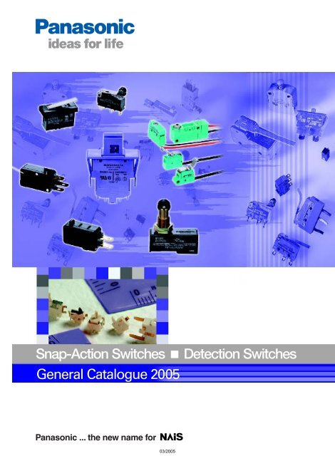
<strong>Snap</strong>-<strong>Action</strong> <strong>Switches</strong> ■ <strong>Detection</strong> <strong>Switches</strong><br />
<strong>General</strong> <strong>Catalogue</strong> <strong>2005</strong><br />
Panasonic ... the new name for
TABLE OF CONTENTS<br />
Page<br />
Selector Chart................................................................4<br />
Technical Terminology & Cautions For Use.............10<br />
Turquoise <strong>Switches</strong> ....................................................14<br />
Notes For Turquoise <strong>Switches</strong>...................................15<br />
Turquoise Stroke <strong>Switches</strong> ........................................17<br />
Turquoise Switch<br />
J Type (ABJ) ..............................................................25<br />
S Type (ABS).............................................................35<br />
V Type (ABV).............................................................46<br />
Basic Switch<br />
NZ (AM1) ...................................................................51<br />
Miniature Switch<br />
QV (AM5)...................................................................60<br />
QV (AM5): Contact gap is more than 1mm type........73<br />
NV (AH7): Heat resistant ...........................................74<br />
Subminiature Switch<br />
FS/FS-T (AV3/AVT3/AVM3/AVL3) ............................80<br />
FS (AV3G):<br />
Contact gap is more than 1mm type..........................92<br />
PS (AVM3P).....................................................94<br />
CS (AV6)....................................................................99<br />
Ultra-miniature Switch<br />
FJ (AH1) ..................................................................104<br />
Smallest <strong>Snap</strong>-action Switch<br />
FU (AV4)..................................................................109<br />
Inter Lock Switch<br />
GX (AGX).................................................................114<br />
GW (AV1) ................................................................118<br />
GL (AGL) .................................................................123<br />
<strong>Detection</strong> Switch<br />
FT-2Way Switch (ABC3)..........................................126<br />
FT-µ (ABC2) ............................................................130<br />
FT (ABC1)................................................................137<br />
FP (ABP8)................................................................140<br />
New FD (ABU8) .......................................................142<br />
Tip (AHF2) ...............................................................144<br />
Standards Chart ........................................................147<br />
1
Matsushita Electric Works Switch Series<br />
Covers All Markets<br />
High Environmental Resistance Turquoise Colored Seal <strong>Switches</strong><br />
P.14<br />
• New silent switch with<br />
both-sided sliding<br />
contact.<br />
• Boosted employability<br />
with ultra-long stroke.<br />
• IP67 type (Immersion<br />
protected)<br />
Automotive Cultivator Multistory car park Electric cart Refrigerator<br />
Turquoise Stroke <strong>Switches</strong><br />
Turquoise <strong>Switches</strong><br />
NEW<br />
13.3<br />
.524<br />
S type<br />
12.8<br />
.504<br />
J type<br />
19.8<br />
.780<br />
36<br />
1.417<br />
V type<br />
10.1<br />
.398<br />
6.5<br />
.256<br />
11.1<br />
.437<br />
15.9<br />
.626<br />
<strong>Snap</strong>-action Switch Series with Plenty of Variation<br />
P.51<br />
• Full lineup of U, J, S, V<br />
and Z types.<br />
Air conditioner<br />
Microwave oven<br />
Vending machine<br />
Vacuum cleaner<br />
Heater<br />
FU <strong>Switches</strong><br />
FJ <strong>Switches</strong><br />
PS <strong>Switches</strong><br />
FS/FS-T <strong>Switches</strong><br />
7.5<br />
.295<br />
5<br />
.197<br />
2.5<br />
.098<br />
6.5<br />
.256<br />
12.8<br />
.504<br />
11.1<br />
.437<br />
19.8<br />
.780<br />
11.1<br />
.437<br />
19.8<br />
.780<br />
11.1<br />
.437<br />
19.8<br />
.780<br />
CS <strong>Switches</strong><br />
NV <strong>Switches</strong><br />
QV <strong>Switches</strong><br />
NZ Basic <strong>Switches</strong><br />
Pin plunger<br />
29.2<br />
1.150<br />
(Heat resistant type)<br />
27.8<br />
1.094<br />
27.8<br />
1.094<br />
49.2<br />
1.937<br />
10<br />
.394<br />
15.9<br />
.626<br />
15.9<br />
.626<br />
24.1<br />
.949<br />
2
Environmental<br />
resistance<br />
Compact<br />
Minute<br />
current type<br />
Miniature <strong>Detection</strong> <strong>Switches</strong><br />
• Suited for mobile<br />
equipment that require<br />
compactness and low<br />
energy consumption.<br />
• High reliability at low<br />
level load.<br />
Smallest worldwide* in its class:<br />
2-directional single ultra-compact detection switch<br />
Mobile phone Digital still camera Laptop computer CD-RW<br />
FT-2 Way <strong>Switches</strong><br />
NEW<br />
5<br />
.197<br />
1.4<br />
.055<br />
5<br />
.197<br />
NEW<br />
Addition<br />
of Long<br />
Stroke<br />
type<br />
FT-µ <strong>Switches</strong><br />
World’s smallest class<br />
3.4<br />
.134<br />
1.4<br />
.055<br />
3.4<br />
.134<br />
1.4<br />
.055<br />
3.5<br />
.138<br />
3.5<br />
.138<br />
3.4<br />
.134<br />
1.4<br />
.055<br />
(1a)<br />
3.4<br />
.134<br />
1.4<br />
(1b)<br />
.055<br />
(Unit: mm inch)<br />
P.126<br />
Silicon audio player<br />
3.5<br />
.138<br />
3.5<br />
.138<br />
FT <strong>Switches</strong><br />
FP <strong>Switches</strong><br />
New FD <strong>Switches</strong><br />
*MEW data as of Aug., 2003.<br />
1.4<br />
.055<br />
5.5<br />
.217 7.1<br />
.280<br />
3.4<br />
.134<br />
2.3<br />
.091<br />
3.4<br />
.134<br />
6.4<br />
.252<br />
6.2<br />
.244<br />
3.0<br />
.118<br />
• Contributes to safety<br />
countermeasures by detecting<br />
machine tilt.<br />
TIP <strong>Switches</strong><br />
Containing a photo sensor<br />
9.3<br />
.366<br />
9.5<br />
.374<br />
Door Interlock Switch for Office Automation Equipment<br />
• Complies with safety standards.<br />
P.114<br />
GX <strong>Switches</strong><br />
GW <strong>Switches</strong><br />
GL <strong>Switches</strong><br />
For 1-circuit line For 1-circuit line For 2-circuit lines<br />
34<br />
1.339<br />
PPC<br />
14<br />
.551<br />
34<br />
1.339<br />
20.15<br />
.793<br />
14.6<br />
.575<br />
27<br />
1.063<br />
30<br />
1.181<br />
3
Switch Selector Chart<br />
• Type of switch<br />
J type<br />
(Stroke switches)<br />
NEW<br />
9.6<br />
.378<br />
13.3<br />
.524<br />
6.5<br />
.256<br />
12.8<br />
.504<br />
Turquoise<br />
J type S type V type<br />
12.5<br />
.492<br />
12.8<br />
.504<br />
11.1<br />
.437<br />
19.8<br />
.780<br />
16.9<br />
.665<br />
19.8<br />
.780<br />
15.9<br />
.626<br />
33<br />
1.299<br />
15.9<br />
.626<br />
36<br />
1.417<br />
• Features<br />
• Compact size and ultralong<br />
stroke<br />
• IP67<br />
• Silent operation<br />
ASQ ABJ ABS<br />
• Ultra-miniature size (12.8 ×<br />
6 × 6.5 mm .504 × .236 ×<br />
.256 inch)<br />
• Adoption of elastomer<br />
double molding technology<br />
and Ultrasonic swaging<br />
technology to uniform<br />
sealing in high production<br />
quantities<br />
• High environmental<br />
resistance<br />
• Subminiature size (19.8 ×<br />
6.4 × 11.1 mm .780 × .252<br />
× .437 inch)<br />
• Adoption of Elastomer<br />
double molding technology<br />
and Ultrasonic swaging<br />
technology to uniform<br />
sealing in high production<br />
quantities<br />
• High environmental<br />
resistance<br />
ABV1<br />
• Miniature size (33 × 10.3 ×<br />
15.9 mm 1.299 × .406 ×<br />
.626 inch)<br />
• Adoption of Ultrasonic<br />
swaging technology and<br />
epoxy sealing to uniform<br />
sealing in high production<br />
quantities<br />
• High environmental<br />
resistance<br />
• O.F. by pin plunger<br />
(gf, Max.)<br />
1.5N (Pin plunger)<br />
1.7N (Leaf lever)<br />
1.5N (Simulated leaf lever)<br />
1.23N<br />
1.96N<br />
2.45N (Long stroke type)<br />
0.98N<br />
1.47N<br />
0.98N<br />
1.96N<br />
• Max. contact rating<br />
(resistive)<br />
• Rating of low-level<br />
circuit type (resistive)<br />
Gold plating on both sides of<br />
sliding contact<br />
100 mA 30 V DC<br />
1 mA 5 V DC<br />
Silver alloy contact Silver alloy contact Silver alloy contact<br />
1.96N type<br />
2 A 125 V AC<br />
2 A 30 V DC<br />
O.F. 1.23N<br />
1 A 125 V AC<br />
1 A 30 V DC<br />
O.F. 2.45N (Long stroke type)<br />
1 A 125 V AC<br />
1 A 30 V DC<br />
Gold-clad contact<br />
0.1 A 125 V AC<br />
0.1 A 30 V DC<br />
5 mA 6 V DC<br />
2 mA 12 V DC<br />
1 mA 24 V DC<br />
2 A 125 V AC<br />
2 A 250 V AC<br />
2 A 30 V DC<br />
0.4 A 125 V DC<br />
Gold-clad contact<br />
(triple layer)<br />
(double layer)<br />
0.1 A 125 V AC<br />
0.1 A 250 V AC<br />
0.1 A 30 V DC<br />
5 mA 6 V DC<br />
2 mA 12 V DC<br />
1 mA 24 V DC<br />
5 A 250 V AC<br />
(O.F. min. 1.96N)<br />
3 A 250V AC<br />
(O.F. 0.98N)<br />
Gold-clad contact<br />
3 A 250 V AC<br />
(O.F. min. 1.96N)<br />
1 A 250 V AC<br />
(O.F. 0.98N)<br />
5 mA 6 V DC<br />
2 mA 12 V DC<br />
1 mA 24 V DC<br />
• Expected<br />
life (min.<br />
ope.)<br />
Electrical<br />
2 × 10 5<br />
(Nominal<br />
rating)<br />
2 × 10 5<br />
(Low-level<br />
rating)<br />
3 × 10 4<br />
(Silver alloy<br />
contact type)<br />
10 5<br />
(Gold-clad<br />
contact type)<br />
5 × 10 4<br />
(Silver alloy<br />
contact type)<br />
2 × 10 5<br />
(Gold-clad<br />
contact type)<br />
10 5<br />
(Nominal<br />
rating)<br />
Mechanical — 10 6 5 × 10 6 5 × 10 6<br />
10 6<br />
(Low-level<br />
rating)<br />
Quickconnect<br />
●<br />
.110<br />
●<br />
.187<br />
Solder ● ● ● ●<br />
• Terminal<br />
style<br />
Screw<br />
PC board ● ● ●<br />
Lead wire ● ● ● ●<br />
(IP67)<br />
Connector<br />
• Contact material<br />
Gold-clad<br />
(Standard) Silver alloy<br />
(Low-level) Gold-clad<br />
(Standard) Silver alloy<br />
(Low-level) Gold-clad<br />
(Standard) Silver alloy<br />
(Low-level) Gold-clad<br />
• UL, CSA,VDE, SEMKO — UL/CSA UL/CSA/VDE/SEMKO UL/CSA/VDE/SEMKO<br />
• Page 17 25 35 46<br />
4
Basic<br />
Miniature<br />
NZ QV NV<br />
heat resistant<br />
Unit: mm inch<br />
49.2<br />
1.937<br />
24.1<br />
.949<br />
15.9<br />
.626<br />
27.8<br />
1.094<br />
15.9<br />
.626<br />
27.8<br />
1.094<br />
• Versatile range for all applications<br />
AM1 AM5 AH7<br />
• Reliable design with shock resistance • Continuous use at 120°C (248°F) possible<br />
• High inrush current resistance<br />
• 0.1 A to 21 A type available<br />
0.69N to 5.30N 0.49N to 3.92N<br />
<br />
0.49N to 3.92N<br />
<br />
0.49N to 1.96N<br />
Silver alloy contact<br />
Silver alloy contact<br />
15 A 125, 250 or 480 V AC<br />
1/8HP 125 V AC<br />
1/4HP 250 V AC<br />
1/2A 125 V DC<br />
1/4A 250 V DC<br />
—<br />
21 A 250 V AC (EOL)*<br />
16 A 250 V AC<br />
11 A 250 V AC<br />
6 A 250 V AC<br />
*Product is end of life<br />
Gold-clad contact<br />
0.1 A 250 V AC<br />
5 mA 6 V DC<br />
2 mA 12 V DC<br />
1 mA 24 V DC<br />
16 A 250 V AC<br />
10 A 250 V AC<br />
5 A 250 V AC<br />
Gold-clad contact<br />
3 A 250 V AC<br />
1 A 250 V AC<br />
5 mA 6 V DC<br />
2 mA 12 V DC<br />
1 mA 24 V DC<br />
5 × 10 5 10 5<br />
(Nominal rating)<br />
2 × 10 6<br />
(Low-level rating)<br />
10 5<br />
2 × 10 7 10 7 10 7<br />
●<br />
.187 .250<br />
●<br />
.187 .250<br />
● ● ●<br />
●<br />
Silver alloy<br />
(Standard) Silver alloy<br />
(Low-level) Gold-clad silver alloy<br />
Silver alloy<br />
UL/CSA UL/CSA/VDE/SEMKO UL/CSA/VDE/SEMKO<br />
51 60 74<br />
5
Switch Selector Chart<br />
FS/FS-T<br />
Subminiature<br />
FS: Greater than 1mm<br />
of contact gap PS CS<br />
• Type of switch<br />
11<br />
.433<br />
19.8<br />
.780<br />
11<br />
.433<br />
19.8<br />
.780<br />
11<br />
.433<br />
19.8<br />
.780<br />
11.1<br />
.437<br />
19.8<br />
.780<br />
10<br />
.394<br />
29.2<br />
1.150<br />
• Features<br />
AV3/AVT3/AVM3/AVL3 AV3 AVM3 AV6<br />
• Consistent quality and high<br />
precision through<br />
sophisticated automatic<br />
fabrication system<br />
• Low-level circuit types<br />
available<br />
• Long life version available<br />
• Contact gap of greater<br />
than 1mm .039inch<br />
• Door inter-lock switch for<br />
OA equipment<br />
• High capacity micro switch<br />
• In-line terminals make<br />
soldering works easy<br />
• Using a connector for<br />
connections significantly<br />
improves operation<br />
effectiveness<br />
• Contact reliability is<br />
achived by simple dust<br />
prevension guard and<br />
gold-clad double layer<br />
contacts<br />
• O.F. by pin plunger<br />
(gf, Max.)<br />
<br />
0.25N<br />
(Gold-clad)<br />
0.49N<br />
0.98N<br />
<br />
1.47N<br />
1.47N 1.47N<br />
0.50N<br />
1.50N<br />
• Max. contact rating<br />
(resistive)<br />
• Rating of low-level<br />
circuit type (resistive)<br />
<br />
3 A 250 V AC<br />
3 A 30 V DC<br />
0.4 A 125 V DC<br />
<br />
5 A 250 V AC<br />
5 A 30 V DC<br />
0.4 A 125 V DC<br />
<br />
0.1 A 250 V AC<br />
(Triple layer)<br />
0.1 A 30 V DC<br />
1 to 100 mA, 5 to 30 V DC<br />
(Double layer)<br />
1 to 100 mA, 5 to 250 V AC<br />
(Triple layer)<br />
3 A 30 V AC 10.1 A 250 V AC 0.1 A 30 V DC<br />
— — —<br />
• Expected<br />
life (min.<br />
ope.)<br />
Electrical 5 × 10 4 10 4 5 × 10 4 2 × 10 5<br />
Mechanical<br />
5 × 10 5<br />
3 × 10 7 (Long life version)<br />
5 × 10 5 3 × 10 7 5 × 10 5<br />
Quickconnect<br />
●<br />
.110<br />
●<br />
.110<br />
Solder ● ● ●<br />
• Terminal<br />
style<br />
Screw<br />
PC board ● ● ●<br />
Lead wire<br />
• Contact material<br />
Connector<br />
(Standard) Silver alloy<br />
(Low-level) Gold-clad triple<br />
layer, double layer<br />
Silver alloy Silver alloy Gold-clad silver alloy<br />
●<br />
• UL, CSA,VDE, SEMKO UL/CSA/VDE/SEMKO UL/CSA/TÜV/SEMKO UL/CSA/(VDE)/SEMKO UL/CSA/TÜV<br />
• Page 80 92 94 99<br />
6
Unit: mm inch<br />
Ultra-miniature<br />
Inter Lock Switch<br />
FJ FU GX GW GL<br />
12.8<br />
.504<br />
6.5<br />
.256<br />
5<br />
.197<br />
7.5<br />
.295<br />
2.5<br />
.098<br />
14<br />
.551<br />
34<br />
1.339<br />
20.15<br />
.793<br />
34<br />
1.339<br />
• Ultra-miniature size (12.8 × 6 ×<br />
6.5 mm/12.7 × 6 × 6 mm .504 ×<br />
.236 × .256 inch/.500 × .236 ×<br />
.236 inch)<br />
• Flux-resistant construction<br />
• Flat terminal<br />
AH1 AV4 AGX AV1 AGL4<br />
• Super miniature size (7.5<br />
× 2.5 × 5 mm .295 × .098<br />
× .197 inch)<br />
• Solder terminal type with<br />
mounting holes available<br />
• Mechanical life 3 × 10 5<br />
14.6<br />
.575<br />
27<br />
1.063<br />
• <strong>Snap</strong>-in mounting type<br />
• Satisfying the<br />
downsizing needs 14<br />
mm .551 inch in depth<br />
• Contact gap of greater<br />
than 4 mm .157 inch<br />
30<br />
1.181<br />
• Dual restoration spring<br />
mechanism<br />
• Insuration distance 8 mm<br />
(snap-in mounting 2<br />
form A and 3 form A<br />
type)<br />
• 2-circuit line–high<br />
capacity load contact<br />
and low-level circuit load<br />
contact<br />
0.74N<br />
1.47N<br />
0.98N<br />
<br />
1a: 3.92N<br />
2a: 3.92N<br />
3a: 5.88N<br />
<br />
1a: 4.90N<br />
2a·3a: 5.88N<br />
1a: 4.90N<br />
1b: 2.94N<br />
1a1b: 5.88N<br />
2a: 7.85N<br />
3a: 9.81N<br />
3.23N<br />
O.F. 1.47N type<br />
3 A 125 V AC<br />
2 A 30 V DC<br />
O.F. 0.74N type<br />
1 A 125 V AC<br />
1 A 30 V DC<br />
<br />
0.5 A 30 V DC<br />
<br />
0.1 A 30 V DC<br />
<br />
10.1 A 250 V AC<br />
<br />
16 A 250 V AC (EOL)*<br />
*Product is end of life<br />
16 A 380 V AC (EOL)*<br />
*Product is end of life<br />
(High capacity load<br />
contact: 1a)<br />
5 A 250 V AC<br />
6 A 30 V DC<br />
(Low-level circuit load<br />
contact: 1a)<br />
0.1 A 125 V AC<br />
10 mA 8 V DC<br />
Au clad contact<br />
5 mA 6 V DC<br />
2 mA 12 V DC<br />
1 mA 24 V DC<br />
— —<br />
5 mA 6 V DC<br />
2 mA 12 V DC<br />
1 mA 24 V DC<br />
3 × 10 4 2 × 10 4<br />
(Au type: 2 × 10 5 )<br />
1 × 10 5 5 × 10 4 10 5<br />
10 6<br />
(O.F. 0.74 N)<br />
5 × 10 5<br />
(O.F. 1.47 N)<br />
3 × 10 5 1 × 10 6 10 6 10 5<br />
●<br />
.250<br />
●<br />
.250<br />
●<br />
●<br />
● ● ●<br />
(Standard) Silver alloy<br />
(Low-level) Gold-clad silver alloy<br />
(Standard) Silver alloy<br />
(Low-level) Gold plating<br />
Silver alloy Silver alloy Silver alloy<br />
UL/CSA —<br />
UL/CSA/VDE/TÜV/<br />
SEMKO<br />
UL/CSA/VDE/TÜV/<br />
SEMKO<br />
UL/CSA/TÜV/SEMKO<br />
104 109 114 118 123<br />
7
Switch Selector Chart<br />
<strong>Detection</strong> Switch<br />
FT-2way SW FT-µ SW FT SW FP<br />
• Type of switch<br />
NEW<br />
5<br />
.197<br />
1.4<br />
.055<br />
5<br />
.197<br />
NEW<br />
3.4<br />
.134<br />
1.4<br />
.055<br />
(Addition of Long stroke type)<br />
3.5<br />
.138<br />
3.4<br />
.134<br />
1.4<br />
.055<br />
3.5<br />
.138<br />
4.8<br />
.189<br />
1.4<br />
.055<br />
5.5<br />
.217<br />
3.4<br />
.134<br />
2.3<br />
.091<br />
• Features<br />
• Detect laterally in two<br />
directions with a single<br />
switch<br />
• Ultra compact and slim for<br />
space saving<br />
• Supports low level loads<br />
with twin gold plate<br />
contacts<br />
ABC3 ABC2 ABC1 ABP8<br />
• World’s smallest<br />
• Ultra-low profile 1.4 mm .055<br />
inch<br />
• Original coil mechanism<br />
serves a high contact<br />
reliability and wiping effect<br />
• Horizontal and vertical<br />
mounting types are available<br />
and detecting from horizontal<br />
and vertical directions is<br />
possible<br />
• High overtravel (1.3 mm .051<br />
inch) makes it easy for<br />
installation. (Long stroke type)<br />
• Ultra-low profile 1.4 mm<br />
.055 inch<br />
• The unique coil springactivated<br />
mechanism<br />
yields a light operating<br />
force and a high overtravel<br />
to faciliate installation<br />
• Detecting from vertical and<br />
horizontal direction is<br />
possible<br />
• Ultra-miniature size<br />
• Low operating force<br />
• High contact reliability<br />
in a low-level load by<br />
sliding crossbar<br />
contacts<br />
• O.F. by pin plunger<br />
(gf, Max.)<br />
0.3N 0.3N 0.3N 0.3N<br />
• Max. contact rating<br />
(resistive)<br />
5 µA<br />
to<br />
10 mA 5 V DC<br />
0.01 mA 5 V DC<br />
to<br />
10 mA 5 V DC<br />
0.01 mA 5 V DC<br />
to<br />
10 mA 5 V DC<br />
0.01 mA 5 V DC<br />
to<br />
100 mA 10 V DC<br />
• Rating of low-level<br />
circuit type (resistive)<br />
— — — —<br />
• Expected<br />
life (min.<br />
ope.)<br />
Electrical<br />
10 5<br />
(5 mA 5 V DC to<br />
10 mA 5 V DC)<br />
10 5<br />
(0.01 mA 5 V DC to<br />
10 mA 5 V DC)<br />
10 5<br />
(0.01 mA 5 V DC to<br />
10 mA 5 V DC)<br />
5 × 10 4<br />
(0.1 A 10 V DC)<br />
10 5<br />
(0.1 mA 5 V DC)<br />
Mechanical — — — —<br />
Quickconnect<br />
Solder<br />
• Terminal<br />
style<br />
Screw<br />
PC board ● ●<br />
SMD<br />
●<br />
SMD<br />
●<br />
SMD<br />
Lead wire<br />
Connector<br />
• Contact material Gold-clad Gold-clad Gold-clad Gold-clad<br />
• UL, CSA,VDE, SEMKO — — — —<br />
• Page 126 130 137 140<br />
8
<strong>Detection</strong> Switch<br />
Unit: mm inch<br />
Unit: mm inch<br />
New FD<br />
Tip SW<br />
6.2<br />
.244<br />
6.4<br />
.252<br />
9.3<br />
.366<br />
9.5<br />
.374<br />
ABU8<br />
AHF2<br />
• Low operating force Max. • Photo sensor inside<br />
0.34N 1.235 oz<br />
• The contact type is<br />
• High contact reliability in a equivalent to normally<br />
low-level load by sliding closed contacts, which<br />
crossbar contacts<br />
satisfies the PL Act.<br />
• Reflow soldering available<br />
0.34N<br />
Operation angle:<br />
25 to 60 degrees<br />
3 mA 6 V DC<br />
to<br />
100 mA 30 V DC<br />
Photo transistor Please refer<br />
to the inside of catalog<br />
— —<br />
5 × 10 4<br />
(0.1 A 30 V DC)<br />
10 5<br />
(1 mA 5 V DC)<br />
10 5<br />
10 5 10 5<br />
●<br />
●<br />
Gold-clad<br />
Silver alloy<br />
— —<br />
142 144<br />
9
TECHNICAL TERMINOLOGY & CAUTIONS FOR USE<br />
TECHNICAL TERMINOLOGY & CAUTIONS FOR USE<br />
TECHNICAL TERMINOLOGY<br />
1. Rated values<br />
Values indicating the characteristics and<br />
performance guarantee standards of the<br />
snap-action switches. The rated current<br />
and rated voltage, for instance, assume<br />
specific conditions (type of load, current,<br />
voltage, frequency, etc.).<br />
2. Mechanical life<br />
The service life when operated at a<br />
preset operating frequency without<br />
passing electricity through the contacts.<br />
(The life test is performed at a switching<br />
frequency of 60 times/minute and<br />
operating speed of 100 mm/second at the<br />
regular cam.)<br />
3. Electrical life<br />
The service life when the rated load is<br />
connected to the contact and switching<br />
operations are performed. (The life test is<br />
performed at a switching frequency of 20<br />
times/minute and operating speed of 100<br />
mm/second at the regular cam.)<br />
4. Contact form<br />
This refers to the components<br />
determining the type of application which<br />
make up the electrical input/output<br />
circuits in the contact.<br />
Switching<br />
type<br />
Normally<br />
closed type<br />
Normally<br />
open type<br />
COM<br />
COM<br />
COM<br />
Terminal symbols<br />
COM: Common terminal<br />
NC: Normally closed terminal<br />
NO: Normally open terminal<br />
5. Insulation resistance<br />
Resistance between noncontinuous<br />
terminals, terminals and metal parts not<br />
carrying current, and between terminals<br />
NC<br />
NO<br />
NC<br />
NO<br />
and the ground.<br />
6. Withstand voltage<br />
Threshold limit value that a high voltage<br />
can be applied to a predetermined<br />
measuring location for one minute<br />
without causing damage to the insulation.<br />
7. Contact resistance<br />
This indicates the electrical resistance at<br />
the contact part. <strong>General</strong>ly, this<br />
resistance includes the conductor<br />
resistance of the spring and terminal<br />
portions.<br />
8. Vibration resistance<br />
Malfunction vibration ... Vibration range<br />
where a closed contact does not open for<br />
longer than a specified time due to<br />
vibrations during use of the snap-action<br />
switches.<br />
9. Shock resistance<br />
Shock durability ... Shock range where<br />
the mechanical shocks received during<br />
snap-action switches transport and<br />
installation do not damage the parts or<br />
harm the operating characteristics.<br />
Malfunction shock ... Shock range where<br />
a closed contact does not open for longer<br />
than a specified time due to shocks<br />
during use of the snap-action switches.<br />
10. Operating Force (O.F.)<br />
The force required to cause contact<br />
snap-action. It is expressed terms of<br />
force applied to the plunger or the<br />
actuator.<br />
11. Release Force (R.F.)<br />
The force to be applied to the plunger or<br />
the actuator at the moment contact snaps<br />
back from operated position to<br />
unoperated position.<br />
12. Pretravel (P.T.)<br />
Distance of the plunger or the actuator<br />
movement from free position to operating<br />
position.<br />
13. Overtravel (O.T.)<br />
The distance which the plunger or the<br />
actuator is permitted to travel after<br />
actuation without any damage to the<br />
switching mechanism.<br />
14. Movement Differential (M.D.)<br />
The distance from operating to release<br />
position of the plunger or the actuator.<br />
15. Operating Position (O.P.)<br />
The position of the plunger or the<br />
actuator when the traveling contacts<br />
snaps with the fixed contact.<br />
16. Free Position (F.P.)<br />
Position of the switch plunger or the<br />
actuator when no force is applied to.<br />
17. Overtravel Position (O.T.P.)<br />
The stopping position of the plunger or<br />
the actuator after total travel.<br />
18. Release Position (R.P.)<br />
The position of the plunger or the<br />
actuator when the traveling contact snaps<br />
back from operating position to its original<br />
position.<br />
The following terminologies are applied to<br />
all our switches.<br />
F.P.<br />
P.T.<br />
O.P.<br />
O.F.<br />
O.T.<br />
T T.P.<br />
T.F.<br />
M.D.<br />
R.P.<br />
R.F.<br />
Center of mounting holes<br />
T.T.<br />
CAUTIONS FOR USE<br />
■ Technical Notes on Mechanical Characteristics<br />
1. Actuation Force and Stroke<br />
may cause actuator damage due to<br />
Adequate stroke setting is the key to high inertia of the drive mechanism. It is<br />
reliability. It is also important that<br />
advisable that the stroke be adjusted with<br />
adequate contact force be ’maintained to the mounting plate or driving mechanism.<br />
ensure high reliability. For a normally The figure at right shows a typical<br />
closed circuit, the driving mechanism example of activation and contact forces<br />
should be set so that the actuator is varying with stroke. In the vicinity of the<br />
normally in the free position. For a<br />
O.P. and R.P., the contact force is<br />
normally open circuit, the actuator should diminished, causing chatter and contact<br />
be pressed to 70% to 100% of the<br />
bounce immediately before or after<br />
specified stroke to absorb possible reversal. For this reason, use the switch<br />
errors.<br />
while giving due consideration to this.<br />
If the stroke is set too close to the<br />
This also causes the snap action switch<br />
operating point (O.P.), this may cause to be sensitive to vibration or physical<br />
unstable contact, and in the worst case impact.<br />
10<br />
Contact force Operating force<br />
OF<br />
RF<br />
NC<br />
On FP<br />
On reversal<br />
On reversal<br />
On OTP<br />
NO<br />
FP RP OP TTP<br />
PT MD OT<br />
Stroke<br />
Stroke
2. Changes in Operation<br />
Characteristics<br />
Exercise design care so that malfunctions<br />
will not occur if the snap action switch<br />
characteristics vary by as much as 20%<br />
from, rated values.<br />
3. Mechanical Conditions for Type<br />
Selection<br />
Actuator type should be selected<br />
according to activation method, activation<br />
TECHNICAL TERMINOLOGY & CAUTIONS FOR USE<br />
speed, activation rate, and activation<br />
frequency.<br />
1) An extremely slow activation speed<br />
may cause unstable contact transfer,<br />
possibly resulting in contact failures or<br />
contact fusion.<br />
2) An extremely high activation speed<br />
may cause damage to contacts or<br />
contact response failure.<br />
4. Driving Mechanism<br />
Use of a driving mechanism which will<br />
cause physical impact to the actuator<br />
should be avoided.<br />
<br />
Bad<br />
Good<br />
■ Technical Notes on Electrical Characteristics<br />
1. The snap-action switch is designed for<br />
AC operations. While it has small contact<br />
gaps and no arc absorber, it may be used<br />
for low-capacity DC operations.<br />
(However, a DC magnetic blow-out switch<br />
is available in the NZ Basic <strong>Switches</strong>.)<br />
2. For applications with very small<br />
switching voltage or current, choose the<br />
dry circuit type.<br />
Small current and voltage Application Range<br />
(Dry Circuit type)<br />
Current (mA)<br />
500<br />
100<br />
50<br />
10<br />
5<br />
2<br />
3. Application to Electronic Circuits<br />
1) The snap-action switch contacts can<br />
sustain bounce or chatter when closed.<br />
Bounce or chatter can cause noise or<br />
pulse count errors when the snap action<br />
switch is used in electronic circuits.<br />
2) If contact bounce or chatter poses<br />
problems in the vicinity of the O.P. and<br />
R.P., use a suitable absorption network,<br />
such as a C/R network.<br />
4. Check the surge current, normal<br />
current and surge duration.<br />
5. Contact resistance given in<br />
performance specifications is measured<br />
with a voltage drop method using 6 to 8 V<br />
DC, 1 A (except for low-level load type).<br />
Contact resistance across COM and NC<br />
terminals is measured in the open<br />
position, while contact resistance across<br />
COM and NO terminals is measured in<br />
the closed position.<br />
6. Ratings are measured under the<br />
following conditions:<br />
Inductive load:<br />
Power factor = 0.6 to 0.7<br />
Time constant = 7 ms or less (DC)<br />
7. To prevent contact fusion failure, be<br />
sure to use a serial resistance for each<br />
capacitive load.<br />
8. If snap action switch operation is<br />
synchronized with the AC supply phase,<br />
this may cause: shortened electrical life,<br />
contact fusion failure, contact transfer, or<br />
other reliability problems.<br />
1<br />
4 8 12 16 20 24<br />
DC voltage (VDC)<br />
■ Cautions in a circuit<br />
1. Contact protection is recommended<br />
when snap-action switches are used in<br />
an inductive load circuit. (except for NZ<br />
Basic <strong>Switches</strong> magnetic blow-out types<br />
for DC)<br />
Circuit diagram<br />
r c R<br />
r<br />
c<br />
R<br />
Notes<br />
1. r = more than 10<br />
ohms<br />
2. In an AC circuit.<br />
Impedance of L is<br />
to be slightly<br />
smaller than<br />
impedance of r<br />
and c.<br />
Can be used for both<br />
AC and DC circuits.<br />
Impedance of r is<br />
nearly equal to<br />
impedance of L.<br />
C: 0.1 µF<br />
2. Do not connect the contacts on<br />
individual switches to different type or<br />
different poles of the power supply.<br />
Examples of power supply<br />
connections (connection to different<br />
poles)<br />
Wrong<br />
Solenoid load<br />
Right<br />
Lamp load<br />
PL<br />
Lamp load<br />
PL<br />
Solenoid load<br />
Load connected to same pole<br />
Example of wrong power supply<br />
connection (connection to different<br />
poles of power supply)<br />
This may lead to mixed DC and AC.<br />
Wrong<br />
3. Avoid circuits which apply voltage<br />
between contacts. (This may lead to<br />
mixed deposition.)<br />
Wrong<br />
AC<br />
DC<br />
Load<br />
L<br />
Load<br />
L<br />
diode<br />
R<br />
For DC circuits only.<br />
L<br />
200V<br />
ZNR<br />
Varistor<br />
R<br />
Can be used for both<br />
AC and DC circuits.<br />
100V<br />
11
TECHNICAL TERMINOLOGY & CAUTIONS FOR USE<br />
■ Mounting state and environment<br />
1. Checking the insulation distance<br />
After mounting and wiring, check the<br />
insulation distance between terminals<br />
and the ground. If the insulation distance<br />
is inadequate, mount insulating material<br />
between as required.<br />
2. Fastening the microswitch body<br />
See the Section “NOTES” for the<br />
individual switch.<br />
3. Position adjustment with effector<br />
The effector should be positioned so that<br />
direct force is not applied to the<br />
pushbutton or actuator in its free position.<br />
The operating force to the pushbutton<br />
should only be applied in a perpendicular<br />
direction.<br />
4. Soldering precautions<br />
1) For manual soldering, lay the terminals<br />
flat (horizontal with the ground) and<br />
quickly perform the soldering operation<br />
using a soldering iron with the<br />
appropriate heat capacity and the proper<br />
amount of solder. Take care that the flux<br />
does not flow into the switch interior by<br />
using a ventilation fan to discharge flux<br />
gas and to prevent contact of the switch<br />
body with the soldering iron tip. Be<br />
careful not to apply force to the lead wires<br />
or the terminal portions immediately after<br />
soldering.<br />
The temperature setting and time<br />
conditions vary depending on the<br />
product. See the Section “NOTES” for<br />
each product.<br />
2) For automatic soldering also, see the<br />
Section “NOTES” for each product.<br />
<br />
Wrong<br />
Soldering iron tip<br />
Correct<br />
5. Avoid using in a silicon atmosphere<br />
Avoid using organic silicon rubber,<br />
adhesives, sealing compounds, oil,<br />
grease, and wires in a silicon<br />
atmosphere.<br />
6. Please consult us when using under<br />
the following conditions:<br />
1) Environments where hydrogen sulfide<br />
or other corrosive gases are present.<br />
2) Environments where gasoline, thinner<br />
or other flammable, explosive gases are<br />
present.<br />
3) Dusty environments (for non-seal type<br />
snap action switches).<br />
4) The perpendicular operating speed<br />
exceeds the allowable operating speed.<br />
5) Switching between different poles.<br />
6) Use in environments not in the<br />
prescribed temperature or humidity<br />
range.<br />
7. Storage precautions<br />
To prevent discoloration due to<br />
sulfurization of the terminals (silverplated),<br />
store the switches in a<br />
polyethylene bag or other suitable airtight<br />
container.<br />
8. Usage, storage, and transport<br />
conditions<br />
1) During usage, storage, or<br />
transportation, avoid locations subject to<br />
direct sunlight and maintain normal<br />
temperature, humidity, and pressure<br />
conditions. The allowable specifications<br />
for environments suitable for usage,<br />
storage, and transportation are given<br />
below.<br />
• Temperature: The allowable<br />
temperature range differs for each switch,<br />
so refer to the switch’s individual<br />
specifications. In addition, when<br />
transporting or storing switches while<br />
they are tube packaged, there are cases<br />
when the temperature may differ from the<br />
allowable range. In this situation, be sure<br />
to consult the individual specifications.<br />
• Humidity: 5 to 85% R.H.<br />
;<br />
;;;;;<br />
85<br />
Humidity, %R.H.<br />
Tolerance range<br />
(Avoid freezing when (Avoid<br />
used at temperatures condensation when<br />
lower than 0°C 32°F) used at temperatures<br />
higher than 0°C 32°F)<br />
5<br />
–40<br />
0<br />
–40 +32<br />
Temperature, °C °F<br />
;;;;;;;;;;<br />
;;;;;;;;;;;<br />
;;;;;;;;;;;;<br />
;;;;;;;;;;;;<br />
+85<br />
+185<br />
• Pressure: 86 to 106 kPa<br />
The humidity range varies with the<br />
temperature. Use within the range<br />
indicated in the graph below.<br />
2) Condensation<br />
Condensation forms when there is a<br />
sudden change in temperature under<br />
high temperature, high humidity<br />
conditions Condensation will cause<br />
deterioration of the switch insulation.<br />
3) Freezing<br />
Condensation or other moisture may<br />
freeze on the switch when the<br />
temperatures is lower than 0°C 32°F. This<br />
causes problems such as sticking of<br />
movable parts or operational time lags.<br />
4) Low temperature, low humidity<br />
environments<br />
The plastic becomes brittle if the switch is<br />
exposed to a low temperature, low<br />
humidity environment for long periods of<br />
time.<br />
5) Storage for extended periods of time<br />
(including transportation periods) at high<br />
temperatures or high humidity levels or in<br />
atmospheres with organic gases or<br />
sulfide gases may cause a sulfide film or<br />
oxide film to form on the surfaces of the<br />
contacts and/or it may interfere with the<br />
functions. Check out the atmosphere in<br />
which the units are to be stored and<br />
transported.<br />
6) In terms of the packing format used,<br />
make every effort to keep the effects of<br />
moisture, organic gases and sulfide<br />
gases to the absolute minimum.<br />
9. We reserve the right to modify<br />
without notice the materials, internal<br />
components, and other parts to<br />
improve product quality.<br />
10. Handling precautions<br />
When handling the switches, be careful<br />
not to drop them on the floor since this<br />
may damage them.<br />
For items 5. and 6., select contact<br />
sulfurization (clipping) prevention<br />
products (FS and Au clad 2-layer<br />
contacts) for use with extremely small<br />
loads or an environment-resistant<br />
Turquoise switch.<br />
11.<br />
1) Failure modes of switches include<br />
short-circuiting, open-circuiting and<br />
temperature rises. If this switch is to be<br />
used in equipment where safety is a<br />
prime consideration, examine the<br />
possible effects of these failures on the<br />
equipment concerned, and ensure safety<br />
by providing protection circuits or<br />
protection devices. In terms of the<br />
systems involved, make provision for<br />
redundancy in the design and take steps<br />
to achieve safety design.<br />
2) The ambient operating temperature<br />
(and humidity) range quoted is the range<br />
in which the switch can be operated on a<br />
continuous basis: it does not mean that<br />
using the switch within the rating<br />
guarantees the durability performance<br />
and environment withstanding<br />
performance of the switch. For details on<br />
the performance guarantee, check the<br />
specifications of each product<br />
concerned.<br />
12
■ Types of actuators<br />
Shape<br />
Class.<br />
TECHNICAL TERMINOLOGY & CAUTIONS FOR USE<br />
Pretravel<br />
(P.T.)<br />
Overtravel<br />
(O. T.)<br />
Operating<br />
Force<br />
(O. F.)<br />
Vibration<br />
Shock<br />
Features<br />
Pin plunger Small Small Large<br />
Outstanding<br />
Appropriate for linear short-stroke action. Pin plunger acts directly on snap<br />
action mechanism, enabling high-precision positioning. Amount of movement<br />
after operation is smallest among all of the actuators, however, so reliable<br />
stopper is required.<br />
Spring small<br />
plunger<br />
Small Medium Large Excellent<br />
Used in much the same way as the pin plunger, but is easier to use because<br />
the amount of movement after operation is larger.<br />
Spring short<br />
plunger<br />
Small Medium Large Good<br />
Pin plunger is short, with large plunger diameter that makes centering easier.<br />
Like small spring plunger, amount of movement after operation is large.<br />
Panel attachment<br />
plunger<br />
Small Large Large Good<br />
Secured to panel with hex or lock nut; used as manual or mechanical plunger.<br />
Amount of movement after operation is extremely large and operation point can<br />
be adjusted by changing attachment position. Can be used in combination with<br />
low-speed cam.<br />
Panel attachment<br />
roller plunger<br />
Small Large Large Possible<br />
This is the panel attachment type with a roller, and can be used with fastmoving<br />
cams and dogs..<br />
Hinge lever Large Medium Small Possible<br />
Little force required for operation. Appropriate for use with low-speed cams and<br />
dogs; has large stroke.<br />
Lever available in various shapes to fit operating unit.<br />
Simulated roller<br />
lever<br />
Large Medium Small Possible Tip of hinge lever is bent into a semi-circle, enabling use as a simple roller type.<br />
Leaf lever Large Large Small Excellent<br />
Play in lever is used to assure maximum stroke. Construction provides for<br />
space where lever is attached, for outstanding resistance to freezing.<br />
Hinge roller lever Large Medium Small Possible<br />
This is a hinge lever with a roller, and can be used with high-speed cams and<br />
dogs.<br />
The force required for pin plunger action is lighter than that of the lever, and the<br />
stroke is longer.<br />
One way action<br />
hinge roller lever<br />
Medium Medium Medium Possible<br />
This is hinge roller lever type, and can operate in relation to an operating unit<br />
from a one way direction, but the roller is bent from the opposite direction and<br />
cannot move.<br />
This can be used to prevent reverse-direction action.<br />
Leaf spring Medium Medium Medium Good<br />
This has a leaf spring with offset yield force and has a large stroke. Ideal for<br />
driving low-speed cams and cylinders. Fulcrum is fixed for high precision. To<br />
prevent leaf damage, movement after operation must be within specified value.<br />
Roller leaf spring Medium Medium Medium Good This is a leaf spring with a roller, and can be used with high-speed cams.<br />
(O.C. reversed<br />
action groove type)<br />
Reverse-action<br />
hinge lever<br />
(O.C. reversed<br />
action groove type)<br />
Reverse-action<br />
hinge roller lever<br />
(O.C. reversed<br />
action groove type)<br />
Reverse-action<br />
hinge roller short<br />
lever<br />
Large Small Medium Excellent<br />
Medium Medium Medium Excellent<br />
Small Medium Large Excellent<br />
This is used for low-speed, low-torque cams.<br />
The lever comes in various shapes to fit the<br />
operating body.<br />
This is a reverse-action hinge lever with a roller<br />
and is appropriate for cam operation. Excellent<br />
resistance to vibration and impact when not<br />
engaged.<br />
This is a shorter version of the reverse-action<br />
hinge lever with a roller and has a larger action<br />
force, but is appropriate for cam operation with<br />
a short stroke. Excellent resistance to vibration<br />
and impact when not engaged.<br />
The plunger is constantly<br />
pressed down by a coiled<br />
spring, and operating the<br />
lever induces reverse action.<br />
Because the plunger is<br />
depressed when not<br />
engaged, vibration and shock<br />
resistance are excellent.<br />
Pressing the plunger too far<br />
does not cause abnormal<br />
force to be applied to the<br />
switch mechanism, so a<br />
stable service life is assured.<br />
Rotating-action<br />
type<br />
Large Large Small Possible<br />
This is a rotating, light-action type that is ideal for detecting paper, coins, and<br />
similar objects.<br />
13
TURQUOISE SWITCHES<br />
TURQUOISE SWITCHES<br />
High Environmental Resistance Turquoise Colored Seal <strong>Switches</strong><br />
Against dust, gas and water<br />
Elastomer double molding technology, an industry first,<br />
and ultrasonic swaging technology contribute to uniform sealing<br />
in high production quantities IP67 type (immersion protected)<br />
Broad lineup: J, S and V models make up over 1,000 types.<br />
J type S type V type<br />
Lineup<br />
Terminal<br />
Actuator<br />
Size<br />
J<br />
type<br />
S<br />
type<br />
V<br />
type<br />
Type<br />
Solder<br />
PC board<br />
Straight<br />
Angle<br />
.110<br />
quick-connect<br />
.187<br />
quick-connect<br />
Wire leads<br />
Contact<br />
Pin plunger<br />
Hinge lever<br />
Short hinge<br />
lever<br />
Long hinge<br />
lever<br />
Simulated roller<br />
lever<br />
Roller lever<br />
Short roller<br />
lever<br />
Leaf lever<br />
● Available<br />
Mounting<br />
hole<br />
Terminals ● ● Au, Ag ● ● ● ● M1.2,<br />
Wire leads ● Au, Ag ● ● ● ● ● M2.3, M3<br />
Terminals ● ● ● ● Au, Ag ● ● ● ● ● ●<br />
Wire leads ● Au, Ag ● ● ● ● ● ● ●<br />
Terminals ● Au, Ag ● ● ● ● ●<br />
Wire leads ● Au, Ag ● ● ● ● ●<br />
M2.3<br />
M3<br />
Ultrasonic swaging process<br />
The rubber cap is securely sealed to<br />
the switch cover during an ultrasonic<br />
swaging process.<br />
Cross section of the rubber cap<br />
Cover Rubber cap Cover Rubber cap<br />
Protective grade of body:<br />
IP67<br />
Dust and immersion<br />
protected type<br />
Rubber cap<br />
Cover<br />
Body<br />
Ultrasonic swaging process: A process which bends the<br />
material through ultrasonic vibration.<br />
Cross section of wire leads type<br />
Conforming<br />
to IP67<br />
Common for dust<br />
protected and<br />
immersion<br />
protected type<br />
Rubber cap<br />
Elastomer<br />
double<br />
molding<br />
Elastomer<br />
double molding<br />
Elastomer: Elastic thermoplastic resin<br />
Epoxy resin<br />
(internal)<br />
Terminal<br />
position<br />
conforming<br />
to IP67<br />
Wire leads<br />
Elastomer double molding<br />
The industry's first elastomer double<br />
molding technology is used to mold<br />
the elastomer to the switch body.<br />
A reliable seal of the body and cover<br />
is achieved.<br />
■ Construction<br />
The dust protected type (IP50) and the<br />
immersion protected type (IP67) pass the<br />
following tests, respectively. The<br />
immersion protected type is especially<br />
tested to check for the entry of water after<br />
soaking for a certain period of time. Avoid<br />
operation where they are immersed in<br />
water.<br />
14<br />
[Test conditions]<br />
• Dust protected type (IP50)<br />
The powder circulation pump may be<br />
replaced by other means suitable to<br />
maintain the talcum powder in<br />
suspension in a closed test chamber. The<br />
talcum powder used shall be able to pass<br />
through a square- meshed sieve the<br />
nominal wire diameter of which is 50 µm<br />
and the nominal width between wires 75<br />
µm. The amount of talcum powder to be<br />
used is 2 kg per cubic metre of the test<br />
chamber volume. The duration of the test<br />
is 8 hours.<br />
• Immersion protected type (IP67)<br />
The lowest point of enclosures should be<br />
least 1,000 mm below the surface of the<br />
water. The duration of the test is 30<br />
minutes.
NOTES FOR TURQUOISE SWITCHES<br />
TURQUOISE SWITCHES IMPORTANT NOTES REGARDING USE<br />
1. Fastening of the switch body<br />
Fasten the switch body onto a smooth<br />
surface using the correct screw as shown<br />
in the chart below and tighten it with the<br />
prescribed torque. Be careful not to<br />
exceed the prescribed torque when<br />
tightening as this may adversely affect<br />
the sealing properties and switch<br />
functioning, and also cause damage. If<br />
using a torque driver, verify that it is set to<br />
the prescribed torque. Also, we<br />
recommend that you use a spring washer<br />
and adhesive to prevent loosening and to<br />
lessen the tightening load on the switch.<br />
Screws Tightening torque<br />
M1.2 Not more than 0.098N·m<br />
ABJ M2.3 Not more than 0.29N·m<br />
M3.0 Not more than 0.29N·m<br />
ABS M2.3 Not more than 0.29N·m<br />
ABV M3.0 Not more than 0.49N·m<br />
2) Fixed pin type<br />
To secure the switch unit, thermally crimp<br />
or press-fit the mounting pins. If the pins<br />
are to be press-fitted, install a guide on<br />
the opposite surface to the mounting pins<br />
to prevent them from slipping out of<br />
position and developing play.<br />
3) Be sure to maintain adequate<br />
insulating clearance between each<br />
terminal and ground.<br />
4) The positioning of the switch should be<br />
such that direct force is not applied to the<br />
pushbutton or actuator in its free position.<br />
The operating force to the pushbutton<br />
should only be applied in a perpendicular<br />
direction.<br />
5) The standard value of overtravel used<br />
should be within the range of 70% to<br />
100% of the rated O.T. value.<br />
6) When soldering the V-type turquoise<br />
switch or the immersion protected type of<br />
the J and S type switches, the sealing<br />
material sometimes forms a lump or<br />
bulge at the base of the terminal or lead.<br />
Be sure to allow enough space for this<br />
when attaching the switch.<br />
2. Soldering operations<br />
1) Manual soldering: use soldering irons<br />
(max. 350°C 662°F) capable of<br />
temperature adjustment. This is to<br />
prevent deterioration due to soldering<br />
heat. Care should be taken not to apply<br />
force to the terminals during soldering.<br />
Specifications<br />
Wattage Soldering time<br />
ABJ 18 W Within 3 seconds<br />
ABS 60 W Within 3 seconds<br />
ABV 60 W Within 5 seconds<br />
2) Terminal portions should not be moved<br />
within 1 minute after soldering.<br />
3. Variance of operating<br />
characteristics<br />
Allow for up to ±20% variation of the<br />
specified characteristics values to<br />
compensate for long term operational<br />
wear of the switch in your design.<br />
4. Cautions regarding use<br />
1) When switching inductive loads<br />
(relays, solenoids, buzzers, etc.), an arc<br />
absorbing circuit is recommended to<br />
protect the contacts.<br />
2) If switching of the contact is<br />
synchronized with the phase of the AC<br />
power, reduced electrical life or welded<br />
contact may occur. Therefore, test the<br />
switch while it is operating under actual<br />
loads for this condition. If found, you may<br />
wish to take corrective action in your<br />
design.<br />
3) In the following operating condition,<br />
the electrical life might be greatly reduced<br />
depending upon the switching load.<br />
Please consult us before use.<br />
• Switching operation at a high or low<br />
speed (near limits specified).<br />
4) If the build up of dust or dirt becomes<br />
so severe that it requires the use of the<br />
attached lever, there is the concern that<br />
the flexible part may be impeded and<br />
return movement may not be possible. In<br />
this situation take the following<br />
precautions:<br />
• Select a product number for a switch<br />
with a higher operation load or use a leaf<br />
type lever.<br />
• Attach a protective cover to the lever.<br />
5) If the leaf lever type switch is<br />
excessively pushed (pushed further than<br />
the operational limit position) or switching<br />
is done at high speed or is accompanied<br />
by the impact, the lever will break. Please<br />
be careful. Also, be careful with the BV<br />
short roller lever type switch as improper<br />
return may result from pressing too<br />
much.<br />
5. Protection from dust, water and<br />
corrosive gas<br />
1) The pin button and the space around<br />
the body cap Turquoise switches are<br />
sealed with elastic material, the terminal<br />
portion is integrally molded. This prevents<br />
dust entry and protects the switch against<br />
corrosive gases. Wireleaded types are<br />
recommended for applications subject to<br />
water or oil splash. However, avoid<br />
soaking these immersion protected types<br />
in oil or water, because they types are not<br />
of completely oil tight construction.<br />
2) Take care that breathing actions don’t<br />
allow water vapor to get inside during<br />
opening and closing or cause rapid<br />
temperature changes.<br />
3) Keep away from environments where<br />
silicon based adhesives, oil or grease are<br />
present as faulty contacts may result<br />
from silicon oxide. Do not use in areas<br />
where flammable or explosive gases from<br />
gasoline and thinner, etc., may be<br />
present.<br />
• Dust protection test<br />
Test conditions:<br />
Dust-protected switches ... Repeatedly<br />
pass pure talc powder through a standard<br />
wire sieve with a 75mm nominal diameter<br />
so that the talc is suspended in the air<br />
around the switch area. Two kilograms of<br />
talc powder should be suspended for<br />
each cubic meter of laboratory space.<br />
The talc suspension should then be left<br />
for eight hours.<br />
Contact resistance<br />
• Waterproof test<br />
Test conditions:<br />
Immersion protected IP67 switches ...<br />
Submerge at 1 m below the water surface<br />
for 30 minutes.<br />
Insulation resistance (MΩ)<br />
1Ω<br />
100mΩ<br />
10mΩ<br />
Standard<br />
value 8 hours<br />
2 4 6 8 10 12 14 16 18 20 22 24<br />
Elapsed time (h)<br />
• Hydrogen sulfide exposure test<br />
Test conditions:<br />
Concentration: 3 ppm<br />
Temperature: 40°C 104°F<br />
Humidity: 75% RH<br />
Contact resistance<br />
1000<br />
100<br />
10<br />
100Ω<br />
10Ω<br />
1Ω<br />
100mΩ<br />
10mΩ<br />
Standard value<br />
30 minutes<br />
2 4 6 8 10 12 14 16 18 20 22 24<br />
Typical products<br />
Elapsed time (h)<br />
0 100 200 300 400 500<br />
Elapsed time (h)<br />
Turquoise switches<br />
6. Oil-proof and chemical-proof<br />
characteristics<br />
The rubber elastomer swells when<br />
exposed to oil and chemicals. The extent<br />
of swelling will vary widely depending on<br />
the type and amount of oil and chemicals.<br />
Check with the actual oil or chemicals<br />
used.<br />
In particular, be aware that solvents such<br />
as freon, chlorine, and toluene cannot be<br />
used.<br />
15
NOTES FOR TURQUOISE SWITCHES<br />
7. Washability (ABJ and ABS)<br />
The Turquoise switch terminal with lead<br />
wires type and without lead wires<br />
typeshare the same main body. As a<br />
result, if the print board terminal type<br />
satisfies the set conditions, then it can<br />
undergo a complete cleaning after<br />
automatic soldering. After soldering is<br />
completed, perform cleaning within the<br />
prescribed temperature and time range,<br />
and pay careful attention to the following<br />
points.<br />
1) Perform proper temperature, time,<br />
drying control in the cleaning process in<br />
order to prevent absorption of the liquid<br />
due to respiratory action. Be particularly<br />
careful that all the water droplets in the<br />
switch area are cleaned off in the final<br />
drying process.<br />
2) Some cleaning liquids (solvents) may<br />
harm the rubber parts. Use water or a<br />
weak alkaline water solution.<br />
3) Ultrasonic cleaning methods may<br />
damage the internal components or<br />
contacts. Use immersion or shower<br />
cleaning methods. In addition to the<br />
above points, the use of automatic<br />
cleaning equipment is particularly<br />
recommended for easy control of the<br />
process temperature and time.The<br />
recommended cleaning conditions for the<br />
Turquoise switches are shown below.<br />
However, please evaluate the actual<br />
cleaning process to verify its suitability for<br />
the switch.<br />
Recommended Cleaning Method<br />
Cleaning<br />
Water or<br />
weak alkaline<br />
water solution<br />
70 deg.C<br />
3 minutes max.<br />
Room<br />
temperature<br />
1 minute<br />
max.<br />
Rinse<br />
Water<br />
Room<br />
temperature<br />
1 minute<br />
70 deg.C max.<br />
3 minutes max.<br />
Drying<br />
90 deg.C<br />
3 minutes min.<br />
(until the water<br />
droplets around<br />
the switch area<br />
are gone)<br />
REFERENCE<br />
1. Dust-protected type<br />
This type of construction prevents dust<br />
that is large enough to have an effect on<br />
operation from getting inside the unit.<br />
This construction is stipulated by<br />
protective classes against solid matter in<br />
the IEC standards (IEC529).<br />
Test conditions: The switch is left for eight<br />
hours in a test chamber with a constant<br />
level of floating pure talc that has passed<br />
through a standard 75mm sieve, in a<br />
concentration of 2kg of talc per cubic<br />
meter of volume in the test chamber.<br />
2. Immersion-protected type<br />
This type of construction prevents any<br />
harmful effects even after the device is<br />
left underwater at a depth of one meter<br />
for thirty minutes. This construction is<br />
stipulated by protective classes against<br />
water in the IEC standards (IEC529).<br />
3. IEC’s IP Codes<br />
The IEC (International Electrotechnical<br />
Commission) has defined the IP<br />
characteristic code that represents the<br />
levels of protection described in IEC<br />
standard 529. The two numbers that<br />
follow the IP code (the characteristics<br />
numbers) indicate the suitability of this<br />
protection for all environmental<br />
conditions.<br />
1st characteristics number<br />
2nd characteristics number<br />
IP<br />
• Level of Protection Indicated by the 1st<br />
Characteristics Number<br />
1st<br />
Characteristics<br />
Number<br />
Protection level<br />
(IEC529/Solid matter)<br />
0 No protection<br />
Protected against solid<br />
1<br />
matter larger than 50mm<br />
Protected against solid<br />
2<br />
matter larger than 12mm<br />
Protected against solid<br />
3<br />
matter larger than 2.5mm<br />
Protected against solid<br />
4<br />
matter larger than 1.0mm<br />
Dust-protected type<br />
Prevents dust that is large<br />
5 enough to have an effect<br />
on operation from getting<br />
inside the unit<br />
Dust-resistant type<br />
6 Prevents dust from getting<br />
inside the unit<br />
• Level of Protection Indicated by the 2nd<br />
Characteristics Number<br />
JIS C0920<br />
Dropletprotected<br />
type I<br />
Dropletprotected<br />
type II<br />
Rainprotected<br />
type<br />
Splashprotected<br />
type<br />
Sprayprotected<br />
type<br />
Waterresistant<br />
type<br />
Immersionprotected<br />
type<br />
Underwater<br />
type<br />
2nd<br />
Characteristics<br />
Number<br />
Protection level<br />
(IEC529/Liquid<br />
matter)<br />
0 No protection<br />
Protected against<br />
water droplets that<br />
1<br />
fall perpendicular to<br />
the unit<br />
Protected against<br />
water droplets that<br />
2 fall from within 15°<br />
of perpendicular to<br />
the unit<br />
Protected against<br />
water droplets that<br />
3 fall from within 60°<br />
of perpendicular to<br />
the unit<br />
Protected against<br />
water that splashes<br />
4<br />
on the unit from any<br />
direction<br />
Free from adverse<br />
effects even if<br />
5 sprayed directly<br />
with water from any<br />
direction<br />
Protected against<br />
water sprayed<br />
6<br />
directly on the unit<br />
from any direction<br />
Water does not get<br />
inside of the unit<br />
when submerged in<br />
7<br />
water according to<br />
the specified<br />
conditions<br />
Unit can be used<br />
8<br />
underwater<br />
Note: Details of test conditions are the same<br />
as JIS C 0920. Please refer to them.<br />
16
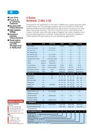
NEW<br />
ULTRA-LONG STROKE,<br />
HIGH CONTACT<br />
RELIABILITY SEAL<br />
SWITCHES<br />
(SAME SIZE AS J TYPE)<br />
FEATURES<br />
1. Same size as J type with ultra-long<br />
stroke. For pin plunger type, it<br />
maintains an ultra-long stroke O.T.<br />
(Over Travel) with over 2.2 mm on the<br />
NO side and over 2.5 mm on the NC<br />
side. Variations in operation can be<br />
absorbed.<br />
2. Since contact pressure does not<br />
depend on the operation stroke, the<br />
range of possible use over the entire<br />
stroke is greatly increased.<br />
(Please refer to operation concept<br />
diagram.)<br />
3. High contact reliability to support<br />
low level switching loads<br />
High contact reliability is maintained with<br />
gold plating on both sides of sliding<br />
contact.<br />
4. Highly effective sealing for<br />
resistance against adverse<br />
environments<br />
Immersion protection type<br />
• JIS C0920 (water-resistance<br />
experiments for electrical machines and<br />
protection rating against incursion of<br />
solid substances)<br />
D2<br />
• JIS D0203 (method for testing moisture<br />
resistance and water resistance in<br />
automotive components)<br />
IP67<br />
• IEC529 (rating for outer shell protection)<br />
ASQ1<br />
TURQUOISE<br />
STROKE<br />
SWITCHES<br />
5. Silent operation<br />
With sliding contact construction there is<br />
no operation noise.<br />
6. Direct operation possible from<br />
lateral direction with pin plunger<br />
(lever-less operation allows space<br />
savings)<br />
7. Contains no harmful substances<br />
(mercury, lead, sexivalent chrome,<br />
cadmium)<br />
TYPICAL APPLICATIONS<br />
1. Automobiles (detection of door<br />
opening and closing and shift lever<br />
position, etc.)<br />
2. Household appliances (propane<br />
stoves, vacuum cleaners, air<br />
conditioners, and washing machines,<br />
etc.)<br />
ORDERING INFORMATION<br />
Ex.<br />
ASQ1<br />
Type of switch<br />
ASQ1: Turquoise<br />
stroke<br />
switch<br />
Size of mounting hole<br />
0: 3 mm .118 inch<br />
standard type<br />
1: 3 mm .118 inch<br />
without boss type<br />
Terminal<br />
2: Wire leads right side type (NC and NO type only)<br />
3: Wire leads left side type (NC and NO type only)<br />
4: Solder terminal<br />
5: PC board terminal<br />
6: Wire leads (bottom type)<br />
Contact form<br />
1: SPDS<br />
2: SPST-NC<br />
(wire lead type only)<br />
3: SPST-NO<br />
(wire lead type only)<br />
Remark: Not every combination is available. Please refer to the following table, “PRODUCT TYPES”.<br />
Actuator<br />
0: Pin plunger<br />
7: Leaf lever<br />
8: Simulated leaf lever<br />
17
ASQ1<br />
OPERATION CONCEPT DIAGRAM (reference)<br />
Contact form: terminal type<br />
Operation load<br />
TF<br />
OF<br />
Operation<br />
load<br />
0<br />
OP (NC)<br />
Standard (mounting boss and<br />
hole center diameter or standoff)<br />
NC<br />
side<br />
OT (NC)<br />
Intermediary OFF range<br />
Contact pressure<br />
0<br />
NO<br />
side<br />
Stroke<br />
OT (NO)<br />
TTP<br />
OP (NO)<br />
FP<br />
Range of possible use<br />
NC side<br />
NO side<br />
PRODUCT TYPES<br />
1. Terminal type (Mounting hole: 3mm standard type/3mm without boss type)<br />
Actuator<br />
Operating force Max.<br />
Mounting hole: 3mm standard type<br />
Solder terminal<br />
Mounting hole: 3mm without boss type<br />
PC board terminal<br />
Pin plunger 1.5N ASQ10410 ASQ11510<br />
Leaf lever 1.7N ASQ10417 ASQ11517<br />
Simulated leaf lever 1.5N ASQ10418 ASQ11518<br />
2. Wire leads bottom type (Mounting hole: 3mm standard type)<br />
Actuator<br />
Operating force Max.<br />
Wire leads bottom type (Mounting hole: 3mm standard type)<br />
Switching type NC type NO type<br />
Pin plunger 1.5N ASQ10610 ASQ10620 ASQ10630<br />
Leaf lever 1.7N ASQ10617 ASQ10627 ASQ10637<br />
Simulated leaf lever 1.5N ASQ10618 ASQ10628 ASQ10638<br />
3. Wire leads side type (Mounting hole: 3mm standard type)<br />
Wire leads right side type<br />
Wire leads left side type<br />
Actuator<br />
Operating force Max. (Mounting hole: 3mm standard type)<br />
(Mounting hole: 3mm standard type)<br />
NC type NO type NC type NO type<br />
Pin plunger 1.5N ASQ10220 ASQ10230 ASQ10320 ASQ10330<br />
Leaf lever 1.7N ASQ10227 ASQ10237 ASQ10327 ASQ10337<br />
Simulated leaf lever 1.5N ASQ10228 ASQ10238 ASQ10328 ASQ10338<br />
RATING<br />
1. Rating<br />
1 mA, 5 V DC to 100 mA, 30 V DC<br />
Note: Please consult us regarding 42 V DC rating.<br />
2. Operation environment and conditions<br />
Item<br />
Specifications<br />
Ambient and storage temperature<br />
–40°C to +85°C –40°F to +185°F (no freezing and condensing)<br />
Allowable operating speed<br />
30 to 500 mm/sec.<br />
Max. operating cycle rate<br />
120 cpm<br />
Note: When switching at low and high speeds or under vibration, or in high-temperature, high-humidity environments, working life and performance may<br />
be reduced remarkably depending on the load capacity. Please consult us.<br />
3. Electrical characteristics<br />
Withstand voltage (Initial)<br />
Insulation resistance (Initial)<br />
Contact resistance (Initial)<br />
Between non-continuous terminals: 600 Vrms, Between each terminal and other exposed metal parts: 1,500 Vrms,<br />
Between each terminal and ground: 1,500 Vrms (at detection current of 1 mA)<br />
Min. 100 MΩ (at 100 V DC insulation resistance meter) (Locations measured same as withstand voltage.)<br />
Max. 1 Ω (at contact resistance meter)<br />
18
ASQ1<br />
4. Characteristics<br />
Item<br />
Specifications<br />
Electrical<br />
5 V DC 1 mA (resistive load) Min. 5 × 10 5 Switching frequency: 20 times/min.<br />
Conduction ratio: 1:1<br />
switching 16 V DC 50 mA (resistive load) Min. 5 × 10 5<br />
Pushbutton operation speed: 100 mm/s<br />
life<br />
30 V DC 100 mA (resistive load) Min. 2 × 10 5 Pushbutton switching position: free position (FP) to operation limit position (TTP)<br />
Vibration resistance<br />
(malfunction vibration resistance)<br />
Shock resistance<br />
(malfunction shock resistance)<br />
Vibration resistance endurance<br />
Terminal strength<br />
Heat resistance<br />
Cold resistance<br />
Humidity resistance<br />
High-temperature, high-humidity resistance<br />
Thermal shock resistance<br />
Water resistance<br />
Single amplitude: 0.75 mm<br />
Amplitude of vibration: 10 to 55 Hz (4 minutes cycle)<br />
Direction and time: 30 minutes each in X, Y and Z directions<br />
Amplitude of vibration: 5 to 200 Hz (10 minutes cycle)<br />
Acceleration: 43.1 m/s 2<br />
Direction and time: 30 minutes each in X, Y and Z directions<br />
Shock value: 980 m/s 2<br />
Direction and time: 5 times each in X, Y and Z directions<br />
Frequency of vibration: 33.3 Hz, Acceleration: 43.1 m/s 2<br />
Direction and time: 8 hours each in X, Y and Z directions<br />
6 N min. (each direction) *Terminal deformation possible.<br />
85°C 185°F 500 houres<br />
–40°C –40°F 500 houres<br />
40°C 104°F 95% RH 500 houres<br />
85°C 185°F 85% RH 500 houres<br />
30 min. at 85°C 185°F to 30 min at –40°C –40°F for 1,000 cycles<br />
Submersed for 30 min. under 1 m of water.<br />
Notes: As long as there are no particular designations, the following conditions apply to the test environment.<br />
• Ambient temperature: 5 to 35°C 41 to 95°F<br />
• Relative humidity: 25 to 85% RH<br />
• Air pressure: 86 to 106 kpa<br />
5. Protective structure<br />
1) JIS C0920: Waterproof type<br />
A concrete testing method is to check for any adverse effect on the structure after leaving it submerged for 30 minutes<br />
under 1 m 3.281 ft of water (with temperature difference between water and switch no larger than 5°C 41°F).<br />
2) IEC 529: IP67 (waterproof type)<br />
A concrete testing method is to check for any adverse effect on the structure after leaving it submerged for 30 minutes<br />
under 1 m 3.281 ft of water (with temperature difference between water and switch no larger than 5°C 41°F).<br />
3) JIS D0203: Equivalent of D2<br />
A concrete testing method is to check for any adverse effect on the structure after leaving it submerged for 30 minutes<br />
under 10 cm 3.937 inch of water (with temperature difference between water and switch no larger than 30°C 86°F).<br />
Note: Names of the standards can be found in the section describing features.<br />
6. Operating characteristics<br />
Actuator Pin plunger Leaf lever Simulated leaf lever<br />
Operating Force (max. O.F.) * Note 2 1.5N 1.7N 1.5N<br />
Total travel Force (max. T.F.) (reference value) (2.0N) (3.1N) (2.8N)<br />
Free Position (max. F.P.)<br />
From mounting boss and hole center line 9.2mm .362inch 11.5mm .453inch 14.4mm .567inch<br />
From standoff 13.4mm .528inch 15.7mm .618inch 18.6mm .732inch<br />
Operating Position on NC side<br />
O.P. (N.C.) * Note 3<br />
Operating Position on NO side<br />
O.P. (N.O.) * Note 4<br />
From mounting boss and hole center line<br />
From standoff<br />
From mounting boss and hole center line<br />
From standoff<br />
8.7±0.3mm<br />
.343±.012inch<br />
12.9±0.3mm<br />
.508±.012inch<br />
8.4±0.3mm<br />
.331±.012inch<br />
12.6±0.3mm<br />
.496±.012inch<br />
Notes: 1. The above indicates the characteristics when operating the pushbutton from the vertical direction.<br />
2. Indicates operation load for NO contact to achieve ON status.<br />
3. Indicates position for NC contact to achieve OFF status.<br />
4. Indicates position for NO contact to achieve ON status.<br />
9.8±0.5mm<br />
.386±.020inch<br />
14.0±0.5mm<br />
.551±.020inch<br />
9.3±0.5mm<br />
.366±.020inch<br />
13.5±0.5mm<br />
.531±.020inch<br />
12.5±0.5mm<br />
.492±.020inch<br />
16.7±0.5mm<br />
.657±.020inch<br />
12.0±0.5mm<br />
.472±.020inch<br />
16.2±0.5mm<br />
.638±.020inch<br />
Over travel on N.C. side (min. O.T. (N.C.)) 2.5mm .098inch 3.1mm .122inch 3.3mm .130inch<br />
Over travel on N.O. side (min. O.T. (N.O.)) 2.2mm .087inch 2.6mm .102inch 2.8mm .110inch<br />
Total Travel Position (T.T.P.) From mounting boss and hole center line (5.9mm .232inch) (6.2mm .244inch) (8.7mm .343inch)<br />
(reference value)<br />
From standoff (10.1mm .398inch) (10.4mm .409inch) (12.9mm .508inch)<br />
19
ASQ1<br />
DIMENSIONS<br />
mm inch <strong>General</strong> tolerance: ±0.25 ±.010<br />
1. Terminal type: Mounting hole 3mm, standard type<br />
Pin plunger<br />
FP 13.4 .528 MAX.<br />
OP (NC) 12.9±0.3 .508±.012<br />
OP (NO) 12.6±0.3 .496±.012<br />
TTP (10.1 .398)<br />
FP 9.2 .362 MAX.<br />
OP (NC) 8.7±0.3 .343±.012<br />
OP (NO) 8.4±0.3 .331±.012<br />
TTP (5.9 .232)<br />
C 0.3 .012<br />
13.3±0.15<br />
.524±.006<br />
5.4<br />
.213<br />
2.7 .106<br />
3.2±0.1<br />
.126±.004<br />
8.3±0.1 .327±.004<br />
3.0 +0.1<br />
−0<br />
.118 +.004<br />
−0<br />
5.1<br />
.201<br />
3.7<br />
.146<br />
5.9<br />
.232<br />
4.2<br />
.165<br />
8.4±0.2<br />
.331±.008<br />
5.4±0.15<br />
.213±.006<br />
1.9 dia.<br />
.075 dia.<br />
Operating Force (max. O.F.) 1.5N<br />
Free<br />
Position<br />
(max. F.P.)<br />
Operating<br />
Position on<br />
NC side<br />
O.P. (N.C.)<br />
Operating<br />
Position on<br />
NO side<br />
O.P. (N.O.)<br />
From mounting boss<br />
and hole center line<br />
From standoff<br />
From mounting boss<br />
and hole center line<br />
From standoff<br />
From mounting boss<br />
and hole center line<br />
From standoff<br />
Over travel on N.C. side<br />
(min. O.T. (N.C.))<br />
Over travel on N.O. side<br />
(min. O.T. (N.O.))<br />
9.2mm<br />
.362inch<br />
13.4mm<br />
.528inch<br />
8.7±0.3mm<br />
.343±.012inch<br />
12.9±0.3mm<br />
.508±.012inch<br />
8.4±0.3mm<br />
.331±.012inch<br />
12.6±0.3mm<br />
.496±.012inch<br />
2.5mm<br />
.098inch<br />
2.2mm<br />
.087inch<br />
3.0 +0<br />
−0.1 dia.<br />
+0<br />
.118−.004<br />
dia.<br />
1.2<br />
.047<br />
2.0<br />
.079<br />
1.5<br />
.059<br />
3.7<br />
.146<br />
0.4<br />
.016<br />
3.0 +0.3<br />
−0.2<br />
.118 +.012<br />
−.008<br />
4.1<br />
.161<br />
0.4<br />
.016<br />
4.53±0.15 4.53±0.15<br />
.178±.006 .178±.006<br />
Leaf lever<br />
FP 15.7 .618 MAX.<br />
OP (NC) 14.0±0.5 .551±.020<br />
OP (NO) 13.5±0.5 .531±.020<br />
TTP (10.4 .409)<br />
FP 11.5 .453 MAX.<br />
OP (NC) 9.8±0.5 .386±.020<br />
OP (NO) 9.3±0.5 .366±.020<br />
TTP (6.2 .244)<br />
C 0.3 .012<br />
13.3±0.15<br />
.524±.006<br />
5.4<br />
.213<br />
2.7 .106<br />
1.9 dia.<br />
.075 dia.<br />
14.0<br />
.551<br />
(18°)<br />
3.2±0.1 .126±.004<br />
8.3±0.1 .327±.004<br />
1.2<br />
.047<br />
0.5<br />
.020<br />
R 1.3 .051<br />
5.1 5.9<br />
.201 .232<br />
3.0 +0.1<br />
−0<br />
.118 +.004<br />
−0<br />
3.7 4.2<br />
.146 .165<br />
8.4±0.2<br />
.331±.008<br />
5.4±0.15<br />
.213±.006<br />
3.3<br />
.130<br />
Operating Force (max. O.F.) 1.7N<br />
Free<br />
Position<br />
(max. F.P.)<br />
Operating<br />
Position on<br />
NC side<br />
O.P. (N.C.)<br />
Operating<br />
Position on<br />
NO side<br />
O.P. (N.O.)<br />
From mounting boss<br />
and hole center line<br />
From standoff<br />
From mounting boss<br />
and hole center line<br />
From standoff<br />
From mounting boss<br />
and hole center line<br />
From standoff<br />
Over travel on N.C. side<br />
(min. O.T. (N.C.))<br />
Over travel on N.O. side<br />
(min. O.T. (N.O.))<br />
11.5mm<br />
.453inch<br />
15.7mm<br />
.618inch<br />
9.8±0.5mm<br />
.386±.020inch<br />
14.0±0.5mm<br />
.551±.020inch<br />
9.3±0.5mm<br />
.366±.020inch<br />
13.5±0.5mm<br />
.531±.020inch<br />
3.1mm<br />
.122inch<br />
2.6mm<br />
.102inch<br />
3.0 +0<br />
−0.1 dia.<br />
+0<br />
.118−.004<br />
dia.<br />
1.2<br />
.047<br />
2.0<br />
.079<br />
4.53±0.15 4.53±0.15<br />
.178±.006 .178±.006<br />
1.5 0.4<br />
.059 .016<br />
3.0 +0.3<br />
−0.2<br />
.118 +.012<br />
−.008<br />
4.1<br />
.161<br />
0.4<br />
.016<br />
Note: When switching at high speed or under shock, lever endurance may drop. Therefore,<br />
please be sure to conduct an endurance evaluation under actual switching conditions.<br />
20
ASQ1<br />
Simulated leaf lever<br />
mm inch <strong>General</strong> tolerance: ±0.25 ±.010<br />
FP 18.6 .732 MAX.<br />
OP (NC) 16.7±0.5 .657±.020<br />
OP (NO) 16.2±0.5 .638±.020<br />
TTP (12.9 .508)<br />
FP 14.4 .567 MAX.<br />
OP (NC) 12.5±0.5 .492±.020<br />
OP (NO) 12.0±0.5 .472±.020<br />
TTP (8.7 .343)<br />
R 2.0<br />
.079<br />
2.8<br />
.110<br />
C 0.3 .012<br />
5.4<br />
.213<br />
2.7 .106<br />
13.3±0.15<br />
.524±.006<br />
1.9 dia.<br />
.075 dia.<br />
15.0<br />
.591<br />
(18°)<br />
3.2±0.1 .126±.004<br />
8.3±0.1 .327±.004<br />
1.2<br />
.047<br />
0.5<br />
.020<br />
R 1.3 .051<br />
5.1 5.9<br />
.201 .232<br />
3.0 +0.1<br />
−0<br />
.118 +.004<br />
−0<br />
3.7 4.2<br />
.146 .165<br />
8.4±0.2<br />
.331±.008<br />
5.4±0.15<br />
.213±.006<br />
3.3<br />
.130<br />
Operating Force (max. O.F.) 1.5N<br />
Free<br />
Position<br />
(max. F.P.)<br />
Operating<br />
Position on<br />
NC side<br />
O.P. (N.C.)<br />
Operating<br />
Position on<br />
NO side<br />
O.P. (N.O.)<br />
From mounting boss<br />
and hole center line<br />
From standoff<br />
From mounting boss<br />
and hole center line<br />
From standoff<br />
From mounting boss<br />
and hole center line<br />
From standoff<br />
Over travel on N.C. side<br />
(min. O.T. (N.C.))<br />
Over travel on N.O. side<br />
(min. O.T. (N.O.))<br />
14.4mm<br />
.567inch<br />
18.6mm<br />
.732inch<br />
12.5±0.5mm<br />
.492±.020inch<br />
16.7±0.5mm<br />
.657±.020inch<br />
12.0±0.5mm<br />
.472±.020inch<br />
16.2±0.5mm<br />
.638±.020inch<br />
3.3mm<br />
.130inch<br />
2.8mm<br />
.110inch<br />
3.0 +0<br />
−0.1 dia.<br />
+0<br />
.118−.004<br />
dia.<br />
1.2<br />
.047<br />
2.0<br />
.079<br />
4.53±0.15 4.53±0.15<br />
.178±.006 .178±.006<br />
1.5 0.4<br />
.059 .016<br />
3.0 +0.3<br />
−0.2<br />
.118 +.012<br />
−.008<br />
4.1<br />
.161<br />
0.4<br />
.016<br />
Note: When switching at high speed or under shock, lever endurance may drop. Therefore,<br />
please be sure to conduct an endurance evaluation under actual switching conditions.<br />
Mounting hole: 3 mm without boss type<br />
PC board terminal<br />
C0.2 .008<br />
0.9<br />
.035<br />
5.08±0.15 5.08±0.15<br />
.200±.006 .200±.006<br />
3.0 +0.3<br />
−0.2<br />
.118 +.012<br />
−.008<br />
PC board pattern<br />
1.0 +0.1<br />
−0<br />
+.004<br />
−0<br />
.039<br />
dia.<br />
dia.<br />
5.08±0.1 5.08±0.1<br />
.200±.004 .200±.004<br />
21
ASQ1<br />
2. Wire leads bottom type: Mounting hole 3mm, standard type mm inch <strong>General</strong> tolerance: ±0.25 ±.010<br />
FP 9.2 .362 MAX.<br />
OP (NC) 8.7±0.3 .343±.012<br />
OP (NO) 8.4±0.3 .331±.012<br />
TTP (5.9 .232)<br />
C 0.3 .012<br />
2.7 .106<br />
5.4<br />
.213<br />
13.3<br />
.524<br />
3.2±0.1<br />
.126±.004<br />
8.4±0.2<br />
.331±.008<br />
5.4±0.15<br />
.213±.006<br />
1.9 dia.<br />
.075 dia.<br />
3.0 +0.1<br />
−0<br />
5.1 5.9<br />
.118 +.004<br />
−0<br />
.201 .232<br />
3.0 +0<br />
−0.1 dia.<br />
+0<br />
.118−.004<br />
dia.<br />
3.2 .126<br />
8.3±0.1 .327±.004<br />
3.7<br />
.146<br />
4.3<br />
.169<br />
4.2 .165<br />
R 0.3 .012<br />
2.6<br />
1.4 dia. .102<br />
.055 dia.<br />
5.0±2<br />
.197±.079<br />
2.2<br />
.087<br />
300±10<br />
11.811±.394<br />
3.6<br />
.142<br />
R 0.3 .012<br />
3. Wire leads right side type: Mounting hole 3mm, standard type<br />
FP 9.2 .362 MAX.<br />
OP (NC) 8.7±0.3 .343±.012<br />
OP (NO) 8.4±0.3 .331±.012<br />
TTP (5.9 .232)<br />
C 0.3 .012<br />
2.7 .106<br />
5.4<br />
.213<br />
13.3<br />
.524<br />
3.2±0.1<br />
.126±.004<br />
3.0 +0.1<br />
−0<br />
.118 +.004<br />
−0<br />
R 0.5 .020<br />
8.4±0.2<br />
.331±.008<br />
5.4±0.15<br />
.213±.006<br />
1.9 dia.<br />
.075 dia.<br />
5.1 5.9<br />
.201 .232<br />
3.0 +0<br />
−0.1 dia.<br />
+0<br />
.118−.004<br />
dia.<br />
8.3±0.1 .327±.004<br />
3.7<br />
.146<br />
1.4 dia.<br />
.055 dia.<br />
R 0.5<br />
.020<br />
4.3<br />
.169<br />
4.5<br />
.177<br />
R 0.2 .008<br />
R 0.5 .020<br />
2.4<br />
.094<br />
300±10<br />
11.811±.394<br />
5.0±2<br />
.197±.079<br />
5.2<br />
.205<br />
22
ASQ1<br />
4. Wire leads left side type: Mounting hole 3mm, standard type mm inch <strong>General</strong> tolerance: ±0.25 ±.010<br />
R 0.5 .020<br />
1.9 dia.<br />
.075 dia.<br />
8.4±0.2<br />
.331±.008<br />
5.4±0.15<br />
.213±.006<br />
FP 9.2 .362 MAX.<br />
OP (NC) 8.7±0.3 .343±.012<br />
OP (NO) 8.4±0.3 .331±.012<br />
TTP (5.9 .232)<br />
2.7<br />
.106<br />
C 0.3 .012<br />
5.4<br />
.213<br />
13.3<br />
.524<br />
3.2±0.1<br />
.126±.004 3.0 +0.1<br />
−0<br />
.118 +.004<br />
−0<br />
5.1 5.9<br />
.201 .232<br />
R 0.5<br />
.020<br />
1.4 dia.<br />
.055 dia.<br />
8.3±0.1 .327±.004<br />
3.7<br />
.146<br />
4.5<br />
.177<br />
4.3<br />
.169<br />
5.2<br />
.205<br />
5.0±2<br />
.197±.079<br />
300±10<br />
11.811±.394<br />
R 0.5 .020 3.0 +0<br />
−0.1 dia.<br />
2.4<br />
+0<br />
.118−.004<br />
dia.<br />
.094<br />
NOTES<br />
1. Soldering conditions<br />
The application of excessive heat upon<br />
the switch when soldering can cause<br />
degradation of switch operation.<br />
Therefore, be sure to keep within the<br />
conditions given below.<br />
1) Manual soldering: use soldering irons<br />
(max. 350°C 662°F, within 3 seconds)<br />
capable of temperature adjustment. This<br />
is to prevent deterioration due to<br />
soldering heat. Care should be taken not<br />
to apply force to the terminals during<br />
soldering.<br />
2) Automatic soldering: Soldering must<br />
be done as below;<br />
260°C 500°F: within 6 seconds<br />
350°C 662°F: within 3 seconds<br />
2. Mounting<br />
Please avoid use in which load would be<br />
applied to the sides (hatch part (both<br />
sides) shown below) of the switch in the<br />
direction indicated by the arrows. This<br />
could cause erroneous operation. Also,<br />
when using a metal installation board,<br />
please make considerations for burr<br />
direction designation and burr<br />
suppressing, etc., so that the burr side<br />
will not be on the switch installation side.<br />
1) To secure the switch, please use an<br />
M3 small screw on a flat surface and<br />
tighten using a maximum torque of 0.29<br />
N·m. It is recommend that spring<br />
washers be used with the screws and<br />
adhesive be applied to lock the screws to<br />
prevent loosening of the screws. Please<br />
make sure not to apply adhesive onto the<br />
moving parts.<br />
2) Be sure to maintain adequate<br />
insulating clearance between each<br />
terminal and ground.<br />
3) Although it is possible to directly<br />
operate the pin plunger type from the<br />
lateral direction, please consult us if<br />
doing so.<br />
4) After mounting please make sure no<br />
pulling load will be applied to the switch<br />
terminals.<br />
5) Range of possible use: Please set the<br />
operation position to within the ranges in<br />
the following table so that there is<br />
sufficient insulation distance and to<br />
maintain contact reliability.<br />
mm inch<br />
Plunger/lever free<br />
Actuator From mounting<br />
boss and hole From standoff<br />
center line<br />
Pin<br />
plunger<br />
Leaf lever<br />
Simulated<br />
leaf lever<br />
Actuator<br />
Pin<br />
plunger<br />
Leaf lever<br />
Simulated<br />
leaf lever<br />
>9.2<br />
>.362<br />
>10.7<br />
>.421<br />
>13.5<br />
>.531<br />
>10.4<br />
>.409<br />
>14.9<br />
>587<br />
>17.7<br />
>697<br />
Plunger/Lever pushed<br />
From mounting<br />
boss and hole From standoff<br />
center line<br />
7.8 to 5.9<br />
.307 to .232<br />
8.4 to 6.2<br />
.331 to .244<br />
11.1 to 8.7<br />
.437 to .343<br />
12.0 to 10.1<br />
.472 to .398<br />
12.6 to 10.4<br />
12.6 to .409<br />
15.3 to 12.9<br />
15.3 to .508<br />
3. Cautions regarding the circuit<br />
1) In order to prevent malfunction in set<br />
devices caused by bounce and chattering<br />
during the ON-OFF switch operation,<br />
please verify the validity of the circuit<br />
under actual operating conditions and<br />
temperature range.<br />
2) When switching inductive loads<br />
(relays, solenoids, buzzers, etc.), an arc<br />
absorbing circuit is recommended to<br />
protect the contacts.<br />
4. Please verify under actual<br />
conditions.<br />
Please be sure to conduct quality<br />
verification under actual operating<br />
conditions in order to increase reliability<br />
during actual use.<br />
5. Switch selection<br />
Please make your selection so that there<br />
will be no problems even if the operating<br />
characteristics vary up to ±20% from the<br />
standard values.<br />
6. Oil-proof and chemical-proof<br />
characteristics<br />
The rubber cap swells when exposed to<br />
oil and chemicals. The extent of swelling<br />
will vary widely depending on the type<br />
and amount of oil and chemicals.<br />
Check with the actual oil or chemicals<br />
used.<br />
In particular, be aware that solvents such<br />
as freon, chlorine, and toluene cannot be<br />
used.<br />
23
ASQ1<br />
7. Environment<br />
• Although continuous operation of the<br />
switch is possible within the range of<br />
ambient temperature (humidity), as the<br />
humidity range differs depending on the<br />
ambient temperature, the humidity range<br />
indicated below should be used.<br />
Continuous use near the limit of the<br />
range should be avoided.<br />
• This humidity range does not guarantee<br />
permanent performance.<br />
;<br />
;;;;;<br />
Humidity, %R.H.<br />
95<br />
Acceptable range<br />
50<br />
(Avoid freezing when (Avoid<br />
used at temperatures condensation when<br />
lower than 0°C 32°F) used at temperatures<br />
higher than 0°C 32°F)<br />
5<br />
–40<br />
0<br />
–40 +32<br />
Temperature, °C °F<br />
;;;;;;;;;;<br />
;;;;;;;;;;;<br />
;;;;;;;;;;;;<br />
;;;;;;;;;;;;<br />
+85<br />
+185<br />
8. Other<br />
1) Please remember that this switch<br />
cannot be used under water. Also,<br />
pleased be warned that switching and<br />
sudden temperature changes with the<br />
presence of water droplets can cause<br />
seepage into the unit.<br />
2) Keep away from environments where<br />
silicon based adhesives, oil or grease are<br />
present as faulty contacts may result<br />
from silicon oxide. Do not use in areas<br />
where flammable or explosive gases from<br />
gasoline and thinner, etc., may be<br />
present.<br />
3) When using the lever type, please be<br />
careful not to apply unreasonable load<br />
from the reverse or lateral directions of<br />
operation.<br />
4) Do not exceed the total travel position<br />
(TTP) and press the actuator. This could<br />
cause operation failure. Also, when<br />
switching at high speed or under shock<br />
even within the operation limit, the<br />
working life may decrease. Therefore,<br />
please be sure to verify the quality under<br />
actual conditions of use.<br />
5) Please make considerations so that<br />
the switch does not become the stopper<br />
for the moving part.<br />
24
Dust protected type<br />
Immersion protected type<br />
(wire leads bottom type)<br />
(Mounting hole<br />
2.3mm .091inch type)<br />
(Mounting hole<br />
2.3mm .091inch type)<br />
HIGH ENVIRONMENTAL<br />
RESISTANCE<br />
ABJ1,2,3,4,5<br />
TURQUOISE<br />
SWITCHES<br />
J TYPE (ABJ)<br />
FEATURES<br />
• Ultra-miniature size (12.8×6.5×6 mm) (.504×.256×.236 inch)<br />
• Sealed construction for use in adverse environment-Sealed<br />
construction by epoxy resin and rubber cap keeps off the cause of<br />
miscontact such as dust. Conforming to IP67* of IEC protective<br />
construction classification<br />
• Elastomer double molding technology, an industry first and ultrasonic<br />
swaging technology contribute to uniform sealing in high production<br />
quantities<br />
• UL/CSA approved<br />
• Long stroke type is available<br />
Since the repeatability is excellent and the play distance (overtrabel) from<br />
the operating position is ample, the task of performing the adjustments<br />
during installation is an easy one.<br />
Operating position accuracy ±0.4 mm ±.016 inch<br />
Overtravel= Min. 2.0 mm .079 inch<br />
As wide range of high pressure is achieved, a stable reliability is ensured<br />
• Leaf lever side wire leads type added. We now offer two types.<br />
M3 type installation hole<br />
Fixed pin type<br />
Immersion protected<br />
(wire leads side type)<br />
Long stroke type<br />
TYPICAL APPLICATIONS<br />
• Industrial use video jack<br />
• Automotives (ex. Device for opening and shutting of automobile<br />
doors)<br />
* Based on the protective construction classification of IEC, items which<br />
satisfy the test requirements are denoted with an IP designation.<br />
ORDERING INFORMATION<br />
Ex. ABJ 1 4 1 0 4 0<br />
Type of<br />
switch<br />
ABJ:<br />
Turquoise<br />
switch<br />
J type<br />
Size of mounting hole<br />
1: 1.2 mm (.047 inch)<br />
2: 2.3 mm (.091 inch)<br />
3: 3 mm (.118 inch)<br />
4: Fixed pin<br />
(right side pin) type<br />
5: Fixed pin<br />
(left side pin) type<br />
Terminal<br />
4: Solder terminal<br />
5: PC board terminal<br />
6: Wire leads (bottom type)<br />
7: Wire leads (right side type)<br />
8: Wire leads (left side type)<br />
Contact<br />
Actuator<br />
arrangement<br />
1: SPDT 0: Pin plunger<br />
2: SPST-NC 2: Hinge lever<br />
3: SPST-NO 4: Simulated roller lever<br />
6: Roller lever<br />
8: Leaf lever (Mounting<br />
hole 3 mm .118 inch<br />
lead wire type only)<br />
L: Long stroke type<br />
Remarks: 1. Standard packing: Dust protected type 100 pcs./carton, 2,000 pcs./case; Immersion protected type 50 pcs./case.<br />
2. SPST-NC and SPST-NO are only available for wire leads type.<br />
3. Leaf lever is only available for wire leads type<br />
4. Not every combination is available. Please refer to the following table, “PRODUCT TYPES”.<br />
Operating force by<br />
pin plunger (max.)<br />
4: 1.23 N<br />
6: 1.96 N<br />
7: 2.45 N<br />
(Long stroke type only)<br />
Contact<br />
0: Silver-alloy<br />
1: Gold-clad<br />
25
ABJ1,2,3,4,5<br />
PRODUCT TYPES<br />
1. Dust protected type (Terminal type)<br />
Mounting hole 1.2mm .047inch type / Mounting hole 2.3mm .091inch type<br />
Silver alloy<br />
Pin plunger<br />
Hinge lever<br />
Actuator<br />
Simulated roller lever<br />
Roller lever<br />
Operating force<br />
Max.<br />
Mounting hole 1.2 mm .047 inch type<br />
Mounting hole<br />
2.3 mm .091 inch type<br />
Solder terminal PC board terminal Solder terminal<br />
1.23 N ABJ141040 ABJ151040 ABJ241040<br />
1.96 N ABJ141060 ABJ151060 ABJ241060<br />
0.39 N ABJ141240 ABJ151240 ABJ241240<br />
0.64 N ABJ141260 ABJ151260 ABJ241260<br />
0.39 N ABJ141440 ABJ151440 ABJ241440<br />
0.64 N ABJ141460 ABJ151460 ABJ241460<br />
0.39 N ABJ141640 ABJ151640 ABJ241640<br />
0.64 N ABJ141660 ABJ151660 ABJ241660<br />
Gold-clad<br />
Actuator<br />
Pin plunger<br />
Hinge lever<br />
Simulated roller lever<br />
Roller lever<br />
Operating force<br />
Max.<br />
Mounting hole<br />
Mounting hole 1.2 mm .047 inch type<br />
2.3 mm .091 inch type<br />
Solder terminal PC board terminal Solder terminal<br />
1.23 N ABJ141041 ABJ151041 ABJ241041<br />
1.96 N ABJ141061 ABJ151061 ABJ241061<br />
0.39 N ABJ141241 ABJ151241 ABJ241241<br />
0.64 N ABJ141261 ABJ151261 ABJ241261<br />
0.39 N ABJ141441 ABJ151441 ABJ241441<br />
0.64 N ABJ141461 ABJ151461 ABJ241461<br />
0.39 N ABJ141641 ABJ151641 ABJ241641<br />
0.64 N ABJ141661 ABJ151661 ABJ241661<br />
2-(1). Immersion protected type (Bottom wire leads type)<br />
Mounting hole 1.2mm .047inch type<br />
Silver alloy<br />
Actuator<br />
Operating force<br />
Mounting hole 1.2 mm .047 inch type<br />
Max.<br />
SPDT SPST-NC SPST-NO<br />
Pin plunger<br />
1.23 N ABJ161040 ABJ162040 ABJ163040<br />
1.96 N ABJ161060 ABJ162060 ABJ163060<br />
Hinge lever<br />
0.39 N ABJ161240 ABJ162240 ABJ163240<br />
0.64 N ABJ161260 ABJ162260 ABJ163260<br />
Simulated roller lever<br />
0.39 N ABJ161440 ABJ162440 ABJ163440<br />
0.64 N ABJ161460 ABJ162460 ABJ163460<br />
Roller lever<br />
0.39 N ABJ161640 ABJ162640 ABJ163640<br />
0.64 N ABJ161660 ABJ162660 ABJ163660<br />
Mounting hole 2.3mm .091inch type<br />
Gold-clad<br />
Actuator<br />
Operating force<br />
Mounting hole 1.2 mm .047 inch type<br />
Max.<br />
SPDT SPST-NC SPST-NO<br />
Pin plunger<br />
1.23 N ABJ161041 ABJ162041 ABJ163041<br />
1.96 N ABJ161061 ABJ162061 ABJ163061<br />
Hinge lever<br />
0.39 N ABJ161241 ABJ162241 ABJ163241<br />
0.64 N ABJ161261 ABJ162261 ABJ163261<br />
Simulated roller lever<br />
0.39 N ABJ161441 ABJ162441 ABJ163441<br />
0.64 N ABJ161461 ABJ162461 ABJ163461<br />
Roller lever<br />
0.39 N ABJ161641 ABJ162641 ABJ163641<br />
0.64 N ABJ161661 ABJ162661 ABJ163661<br />
Remarks: When ordering UL/CSA approved types, please attach suffix “9” to the part number.<br />
26
ABJ1,2,3,4,5<br />
Mounting hole 2.3mm .091inch type<br />
Silver alloy<br />
Actuator<br />
Operating force<br />
Mounting hole 2.3 mm .091 inch type<br />
Max.<br />
SPDT SPST-NC SPST-NO<br />
Pin plunger<br />
1.23 N ABJ261040 ABJ262040 ABJ263040<br />
1.96 N ABJ261060 ABJ262060 ABJ263060<br />
Hinge lever<br />
0.39 N ABJ261240 ABJ262240 ABJ263240<br />
0.64 N ABJ261260 ABJ262260 ABJ263260<br />
Simulated roller lever<br />
0.39 N ABJ261440 ABJ262440 ABJ263440<br />
0.64 N ABJ261460 ABJ262460 ABJ263460<br />
Roller lever<br />
0.39 N ABJ261640 ABJ262640 ABJ263640<br />
0.64 N ABJ261660 ABJ262660 ABJ263660<br />
Gold-clad<br />
Pin plunger<br />
Hinge lever<br />
Mounting hole 3mm .118inch type (Leaf lever type)<br />
Silver alloy<br />
Operating force<br />
Mounting hole 3 mm type<br />
Actuator<br />
Max.<br />
SPDT SPST-NC SPST-NO<br />
0.98 N ABJ361840 ABJ362840 ABJ363840<br />
Leaf lever<br />
1.27 N ABJ361860 ABJ362860 ABJ363860<br />
Gold-clad<br />
2-(2). Immersion protected type (Side wire leads type)<br />
Fixed pin (right side pin) type<br />
Silver alloy<br />
Operating force<br />
Wire leads type<br />
Actuator<br />
Wire leads direction<br />
Max.<br />
SPST-NC<br />
SPST-NO<br />
1.27 N Right ABJ472840 ABJ473840<br />
1.27 N Left ABJ482840 —<br />
Leaf lever<br />
1.76 N Right ABJ472860 ABJ473860<br />
1.76 N Left ABJ482860 —<br />
Gold-clad<br />
Actuator<br />
Simulated roller lever<br />
Roller lever<br />
Leaf lever<br />
Leaf lever<br />
Actuator<br />
Actuator<br />
Operating force<br />
Mounting hole 2.3 mm .091 inch type<br />
Max.<br />
SPDT SPST-NC SPST-NO<br />
1.23 N ABJ261041 ABJ262041 ABJ263041<br />
1.96 N ABJ261061 ABJ262061 ABJ263061<br />
0.39 N ABJ261241 ABJ262241 ABJ263241<br />
0.64 N ABJ261261 ABJ262261 ABJ263261<br />
0.39 N ABJ261441 ABJ262241 ABJ263441<br />
0.64 N ABJ261461 ABJ262461 ABJ263461<br />
0.39 N ABJ261641 ABJ262641 ABJ263641<br />
0.64 N ABJ261661 ABJ262661 ABJ263661<br />
Operating force<br />
Mounting hole 3 mm type<br />
Max.<br />
SPDT SPST-NC SPST-NO<br />
0.98 N ABJ361841 ABJ362841 ABJ363841<br />
1.27 N ABJ361861 ABJ362861 ABJ363861<br />
Operating force<br />
Wire leads type<br />
Wire leads direction<br />
Max.<br />
SPST-NC<br />
SPST-NO<br />
1.27 N Right ABJ472841 ABJ473841<br />
1.27 N Left ABJ482841 —<br />
1.76 N Right ABJ472861 ABJ473861<br />
1.76 N Left ABJ482861 —<br />
Fixed pin (left side pin) type<br />
Silver alloy<br />
Operating force<br />
Wire leads type<br />
Actuator<br />
Wire leads direction<br />
Max.<br />
SPST-NC<br />
SPST-NO<br />
1.27 N Right ABJ572840 ABJ573840<br />
1.27 N Left ABJ582840 —<br />
Leaf lever<br />
1.76 N Right ABJ572860 ABJ573860<br />
1.76 N Left ABJ582860 —<br />
Remarks: When ordering UL/CSA approved types, please attach suffix “9” to the part number.<br />
27
ABJ1,2,3,4,5<br />
Gold-clad<br />
Leaf lever<br />
Mounting hole 3mm .118inch type<br />
Silver alloy<br />
Leaf lever<br />
Gold-clad<br />
Leaf lever<br />
Actuator<br />
Actuator<br />
Actuator<br />
Operating force<br />
Max.<br />
3. Immersion protected type (Bottom wire leads type) Long stroke type<br />
Mounting hole 2.3mm .091inch type<br />
Silver alloy<br />
Operating force<br />
Mounting hole 2.3 mm type<br />
Actuator<br />
Max.<br />
SPDT SPST-NC SPST-NO<br />
Pin plunger (Horizontal) 2.45 N *ABJ261L70 ABJ262L70 ABJ263L70<br />
Remarks: When ordering UL/CSA approved types, please attach suffix “9” to the part number.<br />
APPLICABLE CURRENT RANGE<br />
Wire leads direction<br />
SPST-NC<br />
Wire leads type<br />
SPST-NO<br />
1.27 N Right ABJ572841 ABJ573841<br />
1.27 N Left ABJ582841 —<br />
1.76 N Right ABJ572861 ABJ573861<br />
1.76 N Left ABJ582861 —<br />
Operating force<br />
Wire leads type<br />
Wire leads direction<br />
Max.<br />
SPST-NC<br />
1.27 N<br />
ABJ382840<br />
Left<br />
1.76 N ABJ382860<br />
Operating force<br />
Wire leads type<br />
Wire leads direction<br />
Max.<br />
SPST-NC<br />
1.27 N<br />
ABJ382841<br />
Left<br />
1.76 N ABJ382861<br />
Gold-clad<br />
Operating force<br />
Mounting hole 2.3 mm type<br />
Actuator<br />
Max.<br />
SPDT SPST-NC SPST-NO<br />
Pin plunger (Horizontal) 2.45 N *ABJ261L71 ABJ262L71 ABJ263L71<br />
Contact<br />
Applicable current<br />
range<br />
1mA 0.1A 1A 2A<br />
Max. operating force for<br />
operation (at pin plunger)<br />
1.23 N 1.96 N<br />
Ag<br />
Au<br />
SPECIFICATIONS<br />
1. Contact rating<br />
Type Operating force Max. Standard rating Low-level circuit rating<br />
Silver alloy contact<br />
1.76 N, 1.96 N<br />
2 A 125 V AC<br />
2 A 30 V DC<br />
—<br />
1.23 N, 1.27 N<br />
1 A 125 V AC<br />
1 A 30 V DC<br />
—<br />
Long stroke type<br />
Silver alloy contact<br />
Gold-clad contact<br />
Long stroke type<br />
Gold-clad contact<br />
2.45 N<br />
1.23 N, 1.27 N<br />
1.76 N, 1.96 N<br />
2.45 N<br />
1 A 125 V AC<br />
1 A 30 V DC<br />
0.1 A 125 V AC<br />
0.1 A 125 V AC<br />
0.1 A 30 V DC<br />
—<br />
5 mA 6 V DC<br />
2 mA 12 V DC<br />
1 mA 24 V DC<br />
5 mA 6 V DC<br />
2 mA 12 V DC<br />
1 mA 24 V DC<br />
28
ABJ1,2,3,4,5<br />
2. Characteristics<br />
Mechanical life<br />
(O.T.: Specified value)<br />
Electrical life at rated load<br />
(O.T.: max.)<br />
Insulation resistance<br />
Leaf lever, Long stroke type<br />
Wire leads (right & left side type)<br />
Other types<br />
Silver alloy contact type<br />
Gold-clad contact type<br />
Dielectric strength<br />
Between non-continuous terminals<br />
Between each terminal and other exposed metal parts<br />
Between each terminal and ground<br />
Vibration resistance (Pin plunger type)<br />
Shock resistance (Pin plunger type)<br />
Contact resistance (Initial)<br />
Allowable operating speed (at no load)<br />
Max. operating cycle rate (at no load)<br />
Ambient temperature<br />
Unit weight<br />
Silver contact type<br />
Gold clad contact type<br />
Min. 5×10 5 (at 60 cpm)<br />
Min. 3×10 5 (at 60 cpm)<br />
Min. 10 6 (at 60 cpm)<br />
Min. 3×10 4 (at 20 cpm)<br />
Min. 10 5 (at 20 cpm)<br />
Min. 100 MΩ (at 500 V DC insulation resistance meter)<br />
600 Vrms<br />
1,500 Vrms<br />
1,500 Vrms<br />
10 to 55 Hz at single amplitude of 0.75 mm (Contact opening max. 1 msec.)<br />
Min. 294 m/s 2 {30 G} (Contact opening max. 1 msec.)<br />
Dust protected type (IP50): Max. 50 mΩ<br />
Immersion protected type (IP67): Max. 100 mΩ<br />
(By voltage drop 1 A 6 to 8 V DC)<br />
Dust protected type (IP50): Max. 100 mΩ<br />
Immersion protected type (IP67): Max. 150 mΩ<br />
(By voltage drop 0.1 A 6 to 8 V DC)<br />
1 to 500 mm/sec.<br />
Other type: 120 cpm<br />
Long stroke type: 60 cpm<br />
–40°C to +85°C –40°F to +185°F<br />
Approx. 0.5 g .018 oz (IP50 type)<br />
3. Operating characteristics<br />
Type of actuator<br />
Pin plunger<br />
Hinge lever<br />
Simulated roller lever<br />
Roller lever<br />
Leaf lever<br />
Operating force,<br />
Max.<br />
Release force,<br />
Min<br />
1.23N 0.15N<br />
1.96N 0.25N<br />
0.39N 0.029N<br />
0.64N 0.049N<br />
0.39N 0.029N<br />
0.64N 0.049N<br />
0.39N 0.029N<br />
0.64N 0.049N<br />
Pretravel,<br />
Max. mm inch<br />
Movement<br />
differential,<br />
Max. mm inch<br />
Overtravel,<br />
Min. mm inch<br />
0.6 .024 0.12 .005 0.25 .010<br />
3.0 .118 0.5 .020 0.5 .020<br />
3.0 .118 0.5 .020 0.5 .020<br />
3.0 .118 0.5 .020 0.5 .020<br />
0.98N 0.20N 6.0 .236 1.0 .039 2.5 .098<br />
1.27N 0.22N 2.6 .102 0.5 .020 1.4 .055<br />
1.76N 0.26N 2.6 .102 0.5 .020 1.4 .055<br />
1.27N 0.29N 6.0 .236 1.0 .039 2.5 .098<br />
Operating position,<br />
mm inch<br />
Mounting hole: 1.2 .047<br />
5.5±0.2 .217 ±.008<br />
Mounting hole: 2.3 .091<br />
7.0±0.2 .276 ±.008<br />
Mounting hole: 1.2 .047<br />
6.8±1.0 .286 ±.039<br />
Mounting hole: 2.3 .091<br />
8.3±1.0 .327 ±.039<br />
Mounting hole: 1.2 .047<br />
9.8±1.0 .386 ±.039<br />
Mounting hole: 2.3 .091<br />
11.3±1.0 .445 ±.039<br />
Mounting hole: 1.2 .047<br />
13.1 ±1.0 .516 ±.039<br />
Mounting hole: 2.3 .091<br />
14.6±1.0 .575 ±.039<br />
Mounting hole: 3.0 .118<br />
16.0±2.0 .630 ±.079<br />
Fixed pin type<br />
10.7±0.7 .421 ±.076<br />
Mounting hole: 3.0 .118<br />
16.25±0.7 .640 ±.076<br />
Fixed pin type<br />
10.7±0.7 .421 ±.076<br />
Mounting hole: 3.0 .118<br />
16.25±0.7 .640 ±.076<br />
Mounting hole: 3.0 .118<br />
16.0±2.0 .630 ±.079<br />
Long stroke type 2.45N 0.20N — 0.5 .020 2.0 .079 2.5±0.4 .098 ±.016<br />
Note: The O.P. differs between the 1.2 mm and 2.3 mm dia. installation hole types.<br />
29
ABJ1,2,3,4,5<br />
DIMENSIONS<br />
mm inch <strong>General</strong> tolerance: ±0.25 ±.010<br />
1. Dust protected type<br />
1-(1) PC board terminal<br />
Mounting hole 1.2 mm .047 inch type<br />
Pin plunger<br />
5.4±0.3<br />
0.213±.012<br />
Pretravel 0.6Max.<br />
.024Max<br />
1.5 dia<br />
.059 dia<br />
1.2±0.05 dia.<br />
.047±.002 dia.<br />
5.0±0.15<br />
.197±.006<br />
Operating Position<br />
1.0<br />
5.5±0.2<br />
0.0394 .217±.008<br />
1.1±0.12<br />
.043±.005<br />
5.08±0.1<br />
.200±.039<br />
5.08±0.1<br />
.200±.039<br />
1.5±0.1<br />
.059±.004<br />
0.9<br />
.035<br />
+0.12<br />
2-0<br />
dia.<br />
+.005<br />
.079-0<br />
6.5±0.1<br />
.256±.004<br />
5.08±0.15 5.08±0.15<br />
.200±.006 .200±.006<br />
12.8±0.15<br />
.504±.006<br />
5.50<br />
.217<br />
6-C 0.3<br />
6-C .012<br />
1.6<br />
.063<br />
4.4<br />
.173<br />
6<br />
.236<br />
1.5±0.12<br />
.059±.005<br />
t=0.4<br />
.016<br />
1.25±0.12<br />
.049±.005<br />
Pretravel, Max. mm inch 0.6 .024<br />
Movement differential, Max. mm inch 0.12 .005<br />
Overtravel, Min. mm inch 0.25 .010<br />
Operating<br />
position<br />
Distance from mounting<br />
hole, mm inch<br />
Distance from stand-off,<br />
mm inch<br />
5.5±0.2<br />
.217 ±.088<br />
7±0.3<br />
.276 ±.012<br />
Hinge lever<br />
8.6 4.4±0.4<br />
.339 .173±.016<br />
R13.3<br />
.524<br />
Pretravel 3.0Max.<br />
.118Max<br />
3<br />
.118<br />
1.2±0.05 dia.<br />
.047±.002 dia.<br />
4.2<br />
.165<br />
Operating Position<br />
6.8±1.0<br />
.268±.039<br />
8.3±1.2<br />
.327±.047<br />
5.08±0.1<br />
.200±.039<br />
5.08±0.1<br />
.200±.039<br />
Pretravel, Max. mm inch 3.0 .118<br />
Movement differential, Max. mm inch 0.5 .020<br />
Overtravel, Min. mm inch 0.5 .020<br />
Operating<br />
position<br />
Distance from mounting<br />
hole, mm inch<br />
Distance from stand-off,<br />
mm inch<br />
6.8±1.0<br />
.267 ±.039<br />
8.3±1.2<br />
.327 ±.047<br />
Simulated roller lever<br />
R13.2<br />
.520<br />
R2.5<br />
.098<br />
3.3±0.4<br />
.130±.016<br />
Pretravel 3.0Max.<br />
.118Max<br />
3<br />
.118<br />
1.2±0.05 dia.<br />
.047±.002 dia.<br />
5.08±0.1 5.08±0.1<br />
.200±.039 .200±.039<br />
Operating Position<br />
9.8±1.0<br />
.386±.039<br />
11.3±1.2<br />
.445±.047<br />
Pretravel, Max. mm inch 3.0 .118<br />
Movement differential, Max. mm inch 0.5 .020<br />
Overtravel, Min. mm inch 0.5 .020<br />
Operating<br />
position<br />
Distance from mounting<br />
hole, mm inch<br />
Distance from stand-off,<br />
mm inch<br />
9.8±1.0<br />
.386 ±.039<br />
11.3±1.2<br />
.445 ±.047<br />
Roller lever<br />
3.4–0.4<br />
.134–.016<br />
Pretravel 3.0Max.<br />
.118Max<br />
2.2<br />
.087<br />
1.2–0.05 dia.<br />
.047–.002 dia.<br />
R13.8<br />
R.543<br />
4.8 dia.<br />
.189 dia.<br />
Operating Position<br />
13.1–1.0 14.6–1.2<br />
.516 –.039 .575–.047<br />
5.08–0.1 5.08–0.1<br />
.200–.039 .200–.039<br />
Pretravel, Max. mm inch 3.0 .118<br />
Movement differential, Max. mm inch 0.5 .020<br />
Overtravel, Min. mm inch 0.5 .020<br />
Operating<br />
position<br />
Distance from mounting<br />
hole, mm inch<br />
Distance from stand-off,<br />
mm inch<br />
13.1±1.0<br />
.516 ±.039<br />
14.6±1.0<br />
.575 ±.039<br />
30
ABJ1,2,3,4,5<br />
1-(2) Solder terminal mm inch <strong>General</strong> tolerance: ±0.25 ±.010<br />
Pin plunger<br />
Mounting hole: 1.2 mm .047 inch<br />
Mounting hole: 2.3 mm .091 inch<br />
5.4±0.3<br />
0.213±.012<br />
Pretravel 0.6Max.<br />
.024Max<br />
1.5 dia<br />
.059 dia<br />
4.6±0.3<br />
0.181±.012<br />
Pretravel 0.6Max<br />
.024Max<br />
1.5 dia<br />
.059 dia<br />
5±0.15<br />
.197±.006<br />
1.5<br />
.059<br />
Operating Position<br />
1.0<br />
5.5±0.2<br />
0.0394 .217±.008<br />
6.5±0.15<br />
.256±.006<br />
+0.1<br />
2.4-.05<br />
.094 +.004<br />
-.002<br />
5.7<br />
.224<br />
Operating Position<br />
7±0.2<br />
.276±.008<br />
1.5±0.1<br />
.059±.004<br />
1.2<br />
.047<br />
+0.12<br />
2-1.2-0 dia.<br />
+.005<br />
2-0.47-0<br />
dia.<br />
6.5±0.1<br />
.256±.004<br />
5.08±0.15 5.08±0.15<br />
.200±.006 .200±.006<br />
12.8±0.15<br />
.504±.006<br />
2.2<br />
.087<br />
5<br />
.197<br />
6-C 0.3<br />
6-C .012<br />
0.4<br />
.016<br />
4.4<br />
.173<br />
6<br />
.236<br />
1.5<br />
.059<br />
2<br />
.079<br />
0.5<br />
.020<br />
5.08±0.15<br />
.200±.006<br />
1.2<br />
.047 4.8±0.1<br />
.189±.004<br />
6<br />
.236<br />
12.8±0.15<br />
.504±.006<br />
1.7<br />
.067<br />
2.2<br />
.087<br />
5.08±0.15<br />
.200±.006<br />
dia.<br />
+0.1<br />
2.4-0.05<br />
+.004<br />
.094-.002 dia.<br />
6<br />
.236<br />
0.4<br />
.016<br />
Remarks: Dimensions of the actuator type are the same as corresponding PC board terminal types.<br />
2. Immersion protected type<br />
2-(1) Bottom wire leads type<br />
Pin plunger<br />
Mounting hole: 1.2 mm .047 inch<br />
Mounting hole: 2.3 mm .091 inch<br />
13.9<br />
.547<br />
6.5±0.15<br />
.256±.006<br />
7.50<br />
.295<br />
8.2<br />
.323<br />
300±10<br />
11.811±.394<br />
5±2<br />
.197±.079<br />
6<br />
.236<br />
Thickness of the lead<br />
wire: 0.3 mm 2<br />
UL/CSA approved type:<br />
AWG #20<br />
Color of the lead wire:<br />
COM...Black<br />
N.C. ...Red<br />
N.O. ...White<br />
COM N.O. N.C.<br />
13.9±0.4<br />
.547±.016<br />
300±10<br />
11.811±.394<br />
5±2<br />
.197±.079<br />
Thickness of the lead<br />
wire: 0.3 mm 2<br />
UL/CSA approved type:<br />
AWG #20<br />
Color of the lead wire:<br />
COM ...Black<br />
N.C. ....Red<br />
N.O. ...White<br />
Remarks: 1. As for M1.2 type, other dimensions are the same as those of corresponding PC board terminal types.<br />
As for M2.3 type, other dimensions are the same as those of corresponding solder terminal types.<br />
2. Dimensions of the actuator type are the same as corresponding PC board terminal types.<br />
31
ABJ1,2,3,4,5<br />
Leaf lever mm inch <strong>General</strong> tolerance: ±0.25 ±.010<br />
Mounting hole: 3 mm .118 inch<br />
13±0.1<br />
.512±.004<br />
4.8±0.3<br />
.189±.012<br />
8.6±1 2.5<br />
.339±.039 .098<br />
Pretravel 6 max.<br />
.236 max.<br />
R2.5<br />
.098<br />
9<br />
.354<br />
5<br />
.197<br />
Free Position<br />
(19.0)<br />
(.748)<br />
5<br />
.197<br />
9.25<br />
.364<br />
3.1<br />
+0.1<br />
–0.05<br />
.122 +.004<br />
–.002<br />
3.3<br />
.130<br />
Operating Position<br />
(16±2)<br />
(.630±.079)<br />
Totaltravel Position<br />
(11.5 min.)<br />
(.453)<br />
6.5<br />
.256<br />
3<br />
.118<br />
+0<br />
-0.15<br />
+0<br />
-.006<br />
dia.<br />
dia.<br />
4.4<br />
.173<br />
7.5<br />
.295<br />
R3.25<br />
.128<br />
20.0±0.4<br />
.787±.016<br />
300±10<br />
11.811±.394<br />
5±2<br />
.197±.079<br />
6<br />
.236<br />
Pretravel, Max. mm inch 6.0 .236<br />
Movement differential,<br />
Max. mm inch<br />
1.0 .039<br />
Overtravel, Min mm inch 2.5 .098<br />
Operating<br />
position<br />
Distance from<br />
mounting hole,<br />
mm inch<br />
16.0±2.0<br />
.630 ±.079<br />
2-(2) Side wire leads type<br />
Fixed pin type<br />
Right side pin type<br />
Right wire leads type<br />
6.7<br />
.264<br />
6.0<br />
.236<br />
5.0<br />
.197<br />
5.0 −0.2<br />
+0.0<br />
.197 −.008<br />
+0<br />
Free position (F.P.)<br />
13.05 .514 max.<br />
Operating position (O.P.)<br />
10.7 ±0.7 .421 ±.028<br />
Totaltravel position (T.T.P.)<br />
(8.55)(.337)<br />
R2.0<br />
.079<br />
C0.2<br />
.008<br />
9.53 ±0.1<br />
.375 ±.004<br />
2.2 ±0.05 dia.<br />
2.6 ±0.05<br />
.102 ±.002<br />
9.53<br />
.375<br />
7.6 ±1.0<br />
.299 ±.039 .272 ±.012<br />
.087 ±.002 dia.<br />
6.9 ±0.3<br />
3.45<br />
.136<br />
2.6 ±0.05<br />
8.55<br />
.102 ±.002 .337<br />
16.65<br />
.656<br />
5 ±2<br />
300 ±10<br />
11.811 ±.394 .197 ±.079<br />
Pretravel, Max. mm inch 2.6 .102<br />
Movement differential,<br />
Max. mm inch<br />
0.5 .020<br />
Overtravel, Min mm inch 1.4 .055<br />
Operating<br />
position<br />
Distance from<br />
mounting hole,<br />
mm inch<br />
10.7±0.7<br />
.421 ±.028<br />
32
ABJ1,2,3,4,5<br />
Left wire leads type mm inch <strong>General</strong> tolerance: ±0.25 ±.010<br />
6.7<br />
.264<br />
6.0<br />
.236<br />
5.0<br />
.197<br />
5.0 −0.2<br />
+0.0<br />
.197 −.008<br />
+0<br />
Free position (F.P.)<br />
13.05 .514 max.<br />
Operating position (O.P.)<br />
10.7 ±0.7 .421 ±.028<br />
Totaltravel position (T.T.P.)<br />
(8.55)(.337)<br />
R2.0<br />
.079<br />
C0.2<br />
.008<br />
9.53 ±0.1<br />
.375 ±.004<br />
2.2 ±0.05 dia.<br />
.087 ±.002 dia.<br />
2.6 ±0.05<br />
.102 ±.002<br />
9.53<br />
.375<br />
7.6 ±1.0<br />
6.9 ±0.3<br />
.299 ±.039<br />
3.45<br />
.136<br />
2.6 ±0.05<br />
8.55<br />
.102 ±.002 .337<br />
5 ±2<br />
.197 ±.079 300 ±10<br />
16.65<br />
11.811 ±.394<br />
.656<br />
.272 ±.012<br />
Pretravel, Max. mm inch 2.6 .102<br />
Movement differential,<br />
Max. mm inch<br />
0.5 .020<br />
Overtravel, Min mm inch 1.4 .055<br />
Operating<br />
position<br />
Distance from<br />
mounting hole,<br />
mm inch<br />
10.7±0.7<br />
.421 ±.028<br />
Left side pin type<br />
Right wire leads type<br />
9.53<br />
.375<br />
2.6 ±0.05<br />
C0.2 .102 ±.002<br />
.008 2.2 ±0.05 dia.<br />
.087 ±.002 dia.<br />
9.53 ±0.1<br />
.375 ±.004<br />
5.0 −0.2<br />
+0.0<br />
.197 −.008<br />
+0<br />
6.7<br />
.264<br />
6.0<br />
.236<br />
R2.0<br />
5.0<br />
.079<br />
.197<br />
7.6 ±1.0<br />
6.9 ±0.3<br />
.299 ±.039 .272 ±.012<br />
3.45<br />
.136<br />
2.6 ±0.05<br />
8.55<br />
.102 ±.002 .337<br />
Free position (F.P.)<br />
13.05 .514 max.<br />
Operating position (O.P.)<br />
10.7 ±0.7 .421 ±.028<br />
Totaltravel position (T.T.P.)<br />
(8.55)(.337)<br />
16.65<br />
.656<br />
5 ±2<br />
300 ±10<br />
11.811 ±.394 .197 ±.079<br />
Pretravel, Max. mm inch 2.6 .102<br />
Movement differential,<br />
Max. mm inch<br />
0.5 .020<br />
Overtravel, Min mm inch 1.4 .055<br />
Operating<br />
position<br />
Distance from<br />
mounting hole,<br />
mm inch<br />
10.7±0.7<br />
.421 ±.028<br />
Left wire leads type<br />
C0.2<br />
.008<br />
9.53<br />
.375<br />
2.6 ±0.05<br />
.102 ±.002<br />
2.2 ±0.05 dia.<br />
.087 ±.002 dia.<br />
9.53 ±0.1<br />
.375 ±.004<br />
5.0 −0.2<br />
+0.0<br />
.197 −.008<br />
+0<br />
6.7<br />
.264<br />
6.0<br />
.236<br />
R2.0<br />
5.0<br />
.079<br />
.197<br />
7.6 ±1.0<br />
6.9 ±0.3<br />
.299 ±.039 .272 ±.012<br />
3.45<br />
.136<br />
2.6 ±0.05<br />
8.55<br />
.102 ±.002 .337<br />
5 ±2<br />
.197 ±.079 300 ±10<br />
16.65<br />
11.811 ±.394<br />
.656<br />
Free position (F.P.)<br />
13.05 .514 max.<br />
Operating position (O.P.)<br />
10.7 ±0.7 .421 ±.028<br />
Totaltravel position (T.T.P.)<br />
(8.55)(.337)<br />
Pretravel, Max. mm inch 2.6 .102<br />
Movement differential,<br />
Max. mm inch<br />
0.5 .020<br />
Overtravel, Min mm inch 1.4 .055<br />
Operating<br />
position<br />
Distance from<br />
mounting hole,<br />
mm inch<br />
10.7±0.7<br />
.421 ±.028<br />
33
ABJ1,2,3,4,5<br />
Mounting hole 3mm .118 inch type mm inch <strong>General</strong> tolerance: ±0.25 ±.010<br />
3.0 −0.1<br />
+0<br />
dia.<br />
.118 −.004<br />
+0<br />
dia.<br />
8.4 −0.3<br />
+0.1<br />
.331 −.012<br />
+.004<br />
6.0 +0.2<br />
−0.15<br />
.236 −.006<br />
+.008<br />
5.0<br />
.197<br />
Free position (F.P.)<br />
18.6 .732 max.<br />
Operating position (O.P.)<br />
16.25 ±0.7 .640 ±.028<br />
Totaltravel position (T.T.P.)<br />
(14.1)(.555)<br />
R2.0<br />
.079<br />
C0.30<br />
.012<br />
5.8 ±1.0<br />
12.3<br />
.228 ±.039 .484<br />
1.85 ±0.3<br />
.073 ±.012<br />
9.0<br />
.354<br />
5 ±2<br />
4.0 13.0 ±0.1<br />
.197 ±.079 .157 .512 ±.004<br />
300 ±10<br />
19.6<br />
11.811 ±.394<br />
.772<br />
3.1 −0<br />
+0.1<br />
.122 −0<br />
+.004<br />
3.3<br />
.130 6.0<br />
.236<br />
Pretravel, Max. mm inch 2.6 .102<br />
Movement differential,<br />
Max. mm inch<br />
0.5 .020<br />
Overtravel, Min mm inch 1.4 .055<br />
Operating<br />
position<br />
Distance from<br />
mounting hole,<br />
mm inch<br />
16.25±0.7<br />
.640 ±.028<br />
3. Immersion protected type (Bottom wire leads type) Long stroke type<br />
Mounting hole: 2.3 mm .091 inch<br />
Free position (F.P.)<br />
3.2 .126 max.<br />
Operating position (O.P.)<br />
2.5 ±0.4 .098 ±.016 2.0 dia.<br />
.079 dia.<br />
16.7<br />
4.95<br />
.657<br />
1.0 .195 12.8<br />
.039<br />
.504<br />
6.0 ±0.15<br />
.236 ±.006<br />
8.1 2.4 −0.05<br />
+0.1<br />
.319 .236 +.004<br />
8.2<br />
.323<br />
300 ±10<br />
11.811 ±.394<br />
.764<br />
−.002<br />
19.4<br />
2.5 ±0.1<br />
.098 ±.004<br />
4.8 ±0.1<br />
.189 ±.004<br />
+0.1<br />
2.4 dia.<br />
.236 −0.05<br />
+.004<br />
dia.<br />
−.002<br />
9.0<br />
.354<br />
6.0<br />
.236<br />
+0.<br />
3.0 dia.<br />
.118 −0.15<br />
+0<br />
−.006 dia.<br />
C0.6<br />
.024<br />
5 ±2<br />
.197 ±.079<br />
COM NO NC<br />
13.9 ±0.4<br />
.547 ±.016<br />
Movement differential,<br />
Max. mm inch<br />
0.5 .020<br />
Overtravel, Min mm inch 2.0 .079<br />
Operating position<br />
2.5 ±0.4<br />
.098±.016<br />
34
ORDERING INFORMATION<br />
HIGH ENVIRONMENTAL<br />
RESISTANCE<br />
ABS1,4,5<br />
VDE<br />
TURQUOISE<br />
SWITCHES<br />
S TYPE (ABS)<br />
FEATURES<br />
• Subminiature size (19.8×11.1×6.4 mm) (.780×.437×.252 inch)<br />
• Sealed construction for use in adverse environment-Sealed construction by<br />
epoxy resin and rubber cap keeps off the cause of miscontact such as dust.<br />
Conforming to IP67* of IEC protective construction classification<br />
• Elastomer double molding technology, an industry first and ultrasonic swaging<br />
technology contribute to uniform sealing in high production quantities<br />
• Expansion of low-level circuit type<br />
• We offer an Au clad 2-ply contact type (for small loads) that we developed<br />
specifically for small current and voltage loads in the range of 1 mA to 100 mA<br />
and 5 V to 30 V.<br />
• UL/CSA/VDE/SEMKO approved<br />
(AS for gold-clad twin layer, VDE and SEMKO are not approved.)<br />
* Based on the protective construction classification of IEC, items which satisfy the test<br />
requirements are denoted with an IP designation.<br />
TYPICAL APPLICATIONS<br />
• Automotives<br />
• Home appliances (vacuum cleaner, air purifier)<br />
• Others (gas cookingrange, water vallet)<br />
Ex. ABS 1 1 1 0 4 0<br />
Type of<br />
switch<br />
ABS:<br />
Turquoise switch<br />
S type<br />
Wire and<br />
terminal position<br />
1: Straight type<br />
4: Right angle<br />
5: Left angle<br />
Terminal<br />
1: .110 quick-connect<br />
terminal<br />
4: Solder terminal<br />
5: PC board terminal<br />
6: Wire leads<br />
Contact<br />
arrangement<br />
1: SPDT<br />
2: SPST-NC<br />
3: SPST-NO<br />
Actuator<br />
0: Pin plunger<br />
1: Short hinge lever<br />
2: Hinge lever<br />
3: Long hinge lever<br />
4: Simulated roller lever<br />
6: Roller lever<br />
8: Leaf lever<br />
Remarks: 1. Standard packing: Dust protected type 100 pcs./carton, 1,000 pcs./case; Immersion protected type 50 pcs./case.<br />
2. SPST-NC and SPST-NO are only available for wire leads type.<br />
3. Leaf lever is only available for wire leads type<br />
4. As for wire position:<br />
Operating force by<br />
pin plunger (max.)<br />
4: 0.98 N {100 gf}<br />
5: 1.47 N {150 gf}<br />
Contact<br />
0: Silver-alloy<br />
1: Gold-clad<br />
triple layer<br />
4: Gold-clad<br />
double layer<br />
Straight type<br />
Wire opposite to the<br />
actuator side type<br />
(Right angle)<br />
Wire actuator side type<br />
(Left angle)<br />
5. Not every combination is available. Please refer to the following table, “PRODUCT TYPES”.<br />
35
ABS1,4,5<br />
PRODUCT TYPES<br />
1. Dust protected type<br />
Silver alloy<br />
Pin plunger<br />
Actuator<br />
Short hinge lever<br />
Hinge lever<br />
Long hinge lever<br />
Simulated roller lever<br />
Roller lever<br />
Operating force<br />
Max.<br />
.110<br />
quick-connect<br />
terminal<br />
Solder terminal<br />
PC board terminal<br />
Terminal position<br />
Straight Right angle Left angle<br />
0.98 N ABS111040 ABS141040 ABS151040 ABS451040 ABS551040<br />
1.47 N ABS111050 ABS141050 ABS151050 ABS451050 ABS551050<br />
0.39 N ABS111140 ABS141140 ABS151140 ABS451140 ABS551140<br />
0.59 N ABS111150 ABS141150 ABS151150 ABS451150 ABS551150<br />
0.34 N ABS111240 ABS141240 ABS151240 ABS451240 ABS551240<br />
0.54 N ABS111250 ABS141250 ABS151250 ABS451250 ABS551250<br />
0.25 N ABS111340 ABS141340 ABS151340 ABS451340 ABS551340<br />
0.44 N ABS111350 ABS141350 ABS151350 ABS451350 ABS551350<br />
0.34 N ABS111440 ABS141440 ABS151440 ABS451440 ABS551440<br />
0.54 N ABS111450 ABS141450 ABS151450 ABS451450 ABS551450<br />
0.39 N ABS111640 ABS141640 ABS151640 ABS451640 ABS551640<br />
0.59 N ABS111650 ABS141650 ABS151650 ABS451650 ABS551650<br />
Gold-clad triple layer<br />
Actuator<br />
Pin plunger<br />
Short hinge lever<br />
Hinge lever<br />
Long hinge lever<br />
Simulated roller lever<br />
Roller lever<br />
.110<br />
PC board terminal<br />
Operating force<br />
quick-connect Solder terminal<br />
Terminal position<br />
Max.<br />
terminal<br />
Straight Right angle Left angle<br />
0.98 N ABS111041 ABS141041 ABS151041 ABS451041 ABS551041<br />
1.47 N ABS111051 ABS141051 ABS151051 ABS451051 ABS551051<br />
0.39 N ABS111141 ABS141141 ABS151141 ABS451141 ABS551141<br />
0.59 N ABS111151 ABS141151 ABS151151 ABS451151 ABS551151<br />
0.34 N ABS111241 ABS141241 ABS151241 ABS451241 ABS551241<br />
0.54 N ABS111251 ABS141251 ABS151251 ABS451251 ABS551251<br />
0.25 N ABS111341 ABS141341 ABS151341 ABS451341 ABS551341<br />
0.44 N ABS111351 ABS141351 ABS151351 ABS451351 ABS551351<br />
0.34 N ABS111441 ABS141441 ABS151441 ABS451441 ABS551441<br />
0.54 N ABS111451 ABS141451 ABS151451 ABS451451 ABS551451<br />
0.39 N ABS111641 ABS141641 ABS151641 ABS451641 ABS551641<br />
0.59 N ABS111651 ABS141651 ABS151651 ABS451651 ABS551651<br />
Gold-clad double layer<br />
Pin plunger<br />
Actuator<br />
Short hinge lever<br />
Hinge lever<br />
Long hinge lever<br />
Simulated roller lever<br />
Roller lever<br />
.110<br />
PC board terminal<br />
Operating force<br />
quick-connect Solder terminal<br />
Terminal position<br />
Max.<br />
terminal<br />
Straight Right angle Left angle<br />
0.98 N ABS111044 ABS141044 ABS151044 ABS451044 ABS551044<br />
1.47 N ABS111054 ABS141054 ABS151054 ABS451054 ABS551054<br />
0.39 N ABS111144 ABS141144 ABS151144 ABS451144 ABS551144<br />
0.59 N ABS111154 ABS141154 ABS151154 ABS451154 ABS551154<br />
0.34 N ABS111244 ABS141244 ABS151244 ABS451244 ABS551244<br />
0.54 N ABS111254 ABS141254 ABS151254 ABS451254 ABS551254<br />
0.25 N ABS111344 ABS141344 ABS151344 ABS451344 ABS551344<br />
0.44 N ABS111354 ABS141354 ABS151354 ABS451354 ABS551354<br />
0.34 N ABS111444 ABS141444 ABS151444 ABS451444 ABS551444<br />
0.54 N ABS111454 ABS141454 ABS151454 ABS451454 ABS551454<br />
0.39 N ABS111644 ABS141644 ABS151644 ABS451644 ABS551644<br />
0.59 N ABS111654 ABS141654 ABS151654 ABS451654 ABS551654<br />
Remarks: When ordering UL/CSA approved types, please attach suffix “9" to the part number.<br />
When ordering VDE/SEMKO approved types, please attach suffix “8" to the part number.<br />
36
2. Immersion protected type (3 wire leads type SPDT)<br />
Silver alloy<br />
Pin plunger<br />
Actuator<br />
Short hinge lever<br />
Hinge lever<br />
Long hinge lever<br />
Simulated roller lever<br />
Roller lever<br />
Operating force<br />
Max.<br />
SPDT<br />
Wire position<br />
ABS1,4,5<br />
Straight Right angle Left angle<br />
0.98 N ABS161040 ABS461040 ABS561040<br />
1.47 N ABS161050 ABS461050 ABS561050<br />
0.39 N ABS161140 ABS461140 ABS561140<br />
0.59 N ABS161150 ABS461150 ABS561150<br />
0.34 N ABS161240 ABS461240 ABS561240<br />
0.54 N ABS161250 ABS461250 ABS561250<br />
0.25 N ABS161340 ABS461340 ABS561340<br />
0.44 N ABS161350 ABS461350 ABS561350<br />
0.34 N ABS161440 ABS461440 ABS561440<br />
0.54 N ABS161450 ABS461450 ABS561450<br />
0.39 N ABS161640 ABS461640 ABS561640<br />
0.59 N ABS161650 ABS461650 ABS561650<br />
Gold-clad triple layer<br />
Actuator<br />
Pin plunger<br />
Short hinge lever<br />
Hinge lever<br />
Long hinge lever<br />
Simulated roller lever<br />
Roller lever<br />
SPDT<br />
Operating force<br />
Wire position<br />
Max.<br />
Straight Right angle Left angle<br />
0.98 N ABS161041 ABS461041 ABS561041<br />
1.47 N ABS161051 ABS461051 ABS561051<br />
0.39 N ABS161141 ABS461141 ABS561141<br />
0.59 N ABS161151 ABS461151 ABS561151<br />
0.34 N ABS161241 ABS461241 ABS561241<br />
0.54 N ABS161251 ABS461251 ABS561251<br />
0.25 N ABS161341 ABS461341 ABS561341<br />
0.44 N ABS161351 ABS461351 ABS561351<br />
0.34 N ABS161441 ABS461441 ABS561441<br />
0.54 N ABS161451 ABS461451 ABS561451<br />
0.39 N ABS161641 ABS461641 ABS561641<br />
0.59 N ABS161651 ABS461651 ABS561651<br />
Gold-clad double layer<br />
Pin plunger<br />
Actuator<br />
Short hinge lever<br />
Hinge lever<br />
Long hinge lever<br />
Simulated roller lever<br />
Roller lever<br />
SPDT<br />
Operating force<br />
Wire position<br />
Max.<br />
Straight Right angle Left angle<br />
0.98 N ABS161044 ABS461044 ABS561044<br />
1.47 N ABS161054 ABS461054 ABS561054<br />
0.39 N ABS161144 ABS461144 ABS561144<br />
0.59 N ABS161154 ABS461154 ABS561154<br />
0.34 N ABS161244 ABS461244 ABS561244<br />
0.54 N ABS161254 ABS461254 ABS561254<br />
0.25 N ABS161344 ABS461344 ABS561344<br />
0.44 N ABS161354 ABS461354 ABS561354<br />
0.34 N ABS161444 ABS461444 ABS561444<br />
0.54 N ABS161454 ABS461454 ABS561454<br />
0.39 N ABS161644 ABS461644 ABS561644<br />
0.59 N ABS161654 ABS461654 ABS561654<br />
Remarks: When ordering UL/CSA approved types, please attach suffix “9" to the part number.<br />
When ordering VDE/SEMKO approved types, please attach suffix “8" to the part number.<br />
37
ABS1,4,5<br />
3. Immersion protected type (2 wire leads type SPST-NC)<br />
Silver alloy<br />
Pin plunger<br />
Actuator<br />
Short hinge lever<br />
Hinge lever<br />
Long hinge lever<br />
Simulated roller lever<br />
Roller lever<br />
Operating force<br />
Max.<br />
SPST-NC<br />
Wire position<br />
Straight Right angle Left angle<br />
0.98 N ABS162040 ABS462040 ABS562040<br />
1.47 N ABS162050 ABS462050 ABS562050<br />
0.39 N ABS162140 ABS462140 ABS562140<br />
0.59 N ABS162150 ABS462150 ABS562150<br />
0.34 N ABS162240 ABS462240 ABS562240<br />
0.54 N ABS162250 ABS462250 ABS562250<br />
0.25 N ABS162340 ABS462340 ABS562340<br />
0.44 N ABS162350 ABS462350 ABS562350<br />
0.34 N ABS162440 ABS462440 ABS562440<br />
0.54 N ABS162450 ABS462450 ABS562450<br />
0.39 N ABS162640 ABS462640 ABS562640<br />
0.59 N ABS162650 ABS462650 ABS562650<br />
Gold-clad triple layer<br />
Actuator<br />
Pin plunger<br />
Short hinge lever<br />
Hinge lever<br />
Long hinge lever<br />
Simulated roller lever<br />
Roller lever<br />
SPST-NC<br />
Operating force<br />
Wire position<br />
Max.<br />
Straight Right angle Left angle<br />
0.98 N ABS162041 ABS462041 ABS562041<br />
1.47 N ABS162051 ABS462051 ABS562051<br />
0.39 N ABS162141 ABS462141 ABS562141<br />
0.59 N ABS162151 ABS462151 ABS562151<br />
0.34 N ABS162241 ABS462241 ABS562241<br />
0.54 N ABS162251 ABS462251 ABS562251<br />
0.25 N ABS162341 ABS462341 ABS562341<br />
0.44 N ABS162351 ABS462351 ABS562351<br />
0.34 N ABS162441 ABS462441 ABS562441<br />
0.54 N ABS162451 ABS462451 ABS562451<br />
0.39 N ABS162641 ABS462641 ABS562641<br />
0.59 N ABS162651 ABS462651 ABS562651<br />
Gold-clad double layer<br />
Pin plunger<br />
Actuator<br />
Short hinge lever<br />
Hinge lever<br />
Long hinge lever<br />
Simulated roller lever<br />
Roller lever<br />
SPST-NC<br />
Operating force<br />
Wire position<br />
Max.<br />
Straight Right angle Left angle<br />
0.98 N ABS162044 ABS462044 ABS562044<br />
1.47 N ABS162054 ABS462054 ABS562054<br />
0.39 N ABS162144 ABS462144 ABS562144<br />
0.59 N ABS162154 ABS462154 ABS562154<br />
0.34 N ABS162244 ABS462244 ABS562244<br />
0.54 N ABS162254 ABS462254 ABS562254<br />
0.25 N ABS162344 ABS462344 ABS562344<br />
0.44 N ABS162354 ABS462354 ABS562354<br />
0.34 N ABS162444 ABS462444 ABS562444<br />
0.54 N ABS162454 ABS462454 ABS562454<br />
0.39 N ABS162644 ABS462644 ABS562644<br />
0.59 N ABS162654 ABS462654 ABS562654<br />
Remarks: When ordering UL/CSA approved types, please attach suffix “9" to the part number.<br />
When ordering VDE/SEMKO approved types, please attach suffix “8" to the part number.<br />
38
4. Immersion protected type (2 wire leads type SPST-NO)<br />
Silver alloy<br />
Pin plunger<br />
Actuator<br />
Short hinge lever<br />
Hinge lever<br />
Long hinge lever<br />
Simulated roller lever<br />
Roller lever<br />
Operating force<br />
Max.<br />
SPST-NO<br />
Wire position<br />
ABS1,4,5<br />
Straight Right angle Left angle<br />
0.98 N ABS163040 ABS463040 ABS563040<br />
1.47 N ABS163050 ABS463050 ABS563050<br />
0.39 N ABS163140 ABS463140 ABS563140<br />
0.59 N ABS163150 ABS463150 ABS563150<br />
0.34 N ABS163240 ABS463240 ABS563240<br />
0.54 N ABS163250 ABS463250 ABS563250<br />
0.25 N ABS163340 ABS463340 ABS563340<br />
0.44 N ABS163350 ABS463350 ABS563350<br />
0.34 N ABS163440 ABS463440 ABS563440<br />
0.54 N ABS163450 ABS463450 ABS563450<br />
0.39 N ABS163640 ABS463640 ABS563640<br />
0.59 N ABS163650 ABS463650 ABS563650<br />
Gold-clad triple layer<br />
Actuator<br />
Pin plunger<br />
Short hinge lever<br />
Hinge lever<br />
Long hinge lever<br />
Simulated roller lever<br />
Roller lever<br />
SPST-NO<br />
Operating force<br />
Wire position<br />
Max.<br />
Straight Right angle Left angle<br />
0.98 N ABS163041 ABS463041 ABS563041<br />
1.47 N ABS163051 ABS463051 ABS563051<br />
0.39 N ABS163141 ABS463141 ABS563141<br />
0.59 N ABS163151 ABS463151 ABS563151<br />
0.34 N ABS163241 ABS463241 ABS563241<br />
0.54 N ABS163251 ABS463251 ABS563251<br />
0.25 N ABS163341 ABS463341 ABS563341<br />
0.44 N ABS163351 ABS463351 ABS563351<br />
0.34 N ABS163441 ABS463441 ABS563441<br />
0.54 N ABS163451 ABS463451 ABS563451<br />
0.39 N ABS163641 ABS463641 ABS563641<br />
0.59 N ABS163651 ABS463651 ABS563651<br />
Gold-clad double layer<br />
Pin plunger<br />
Actuator<br />
Short hinge lever<br />
Hinge lever<br />
Long hinge lever<br />
Simulated roller lever<br />
Roller lever<br />
SPST-NO<br />
Operating force<br />
Wire position<br />
Max.<br />
Straight Right angle Left angle<br />
0.98 N ABS163044 ABS463044 ABS563044<br />
1.47 N ABS163054 ABS463054 ABS563054<br />
0.39 N ABS163144 ABS463144 ABS563144<br />
0.59 N ABS163154 ABS463154 ABS563154<br />
0.34 N ABS163244 ABS463244 ABS563244<br />
0.54 N ABS163254 ABS463254 ABS563254<br />
0.25 N ABS163344 ABS463344 ABS563344<br />
0.44 N ABS163354 ABS463354 ABS563354<br />
0.34 N ABS163444 ABS463444 ABS563444<br />
0.54 N ABS163454 ABS463454 ABS563454<br />
0.39 N ABS163644 ABS463644 ABS563644<br />
0.59 N ABS163654 ABS463654 ABS563654<br />
Remarks: When ordering UL/CSA approved types, please attach suffix “9" to the part number.<br />
When ordering VDE/SEMKO approved types, please attach suffix “8" to the part number.<br />
39
ABS1,4,5<br />
5. Immersion protected type (3 wire leads type SPDT)<br />
• Leaf lever type<br />
Silver alloy<br />
Leaf lever<br />
Actuator<br />
Operating force<br />
Max.<br />
SPDT<br />
Wire position<br />
Straight Right angle Left angle<br />
0.88 N ABS161840 ABS461840 ABS561840<br />
1.08 N ABS161850 ABS461850 ABS561850<br />
Gold-clad triple layer<br />
Actuator<br />
Leaf lever<br />
Gold-clad double layer<br />
Actuator<br />
Leaf lever<br />
SPDT<br />
Operating force<br />
Wire position<br />
Max.<br />
Straight Right angle Left angle<br />
0.88 N ABS161841 ABS461841 ABS561841<br />
1.08 N ABS161851 ABS461851 ABS561851<br />
SPDT<br />
Operating force<br />
Wire position<br />
Max.<br />
Straight Right angle Left angle<br />
0.88 N ABS161844 ABS461844 ABS561844<br />
1.08 N ABS161854 ABS461854 ABS561854<br />
6. Immersion protected type (2 wire leads type SPST-NC)<br />
• Leaf lever type<br />
Silver alloy<br />
SPST-NC<br />
Operating force<br />
Actuator<br />
Wire position<br />
Max.<br />
Straight Right angle Left angle<br />
0.88 N ABS162840 ABS462840 ABS562840<br />
Leaf lever<br />
1.08 N ABS162850 ABS462850 ABS562850<br />
Gold-clad triple layer<br />
Actuator<br />
Leaf lever<br />
Gold-clad double layer<br />
Actuator<br />
Leaf lever<br />
SPST-NC<br />
Operating force<br />
Wire position<br />
Max.<br />
Straight Right angle Left angle<br />
0.88 N ABS162841 ABS462841 ABS562841<br />
1.08 N ABS162851 ABS462851 ABS562851<br />
SPST-NC<br />
Operating force<br />
Wire position<br />
Max.<br />
Straight Right angle Left angle<br />
0.88 N ABS162844 ABS462844 ABS562844<br />
1.08 N ABS162854 ABS462854 ABS562854<br />
7. Immersion protected type (2 wire leads type SPST-NO)<br />
• Leaf lever type<br />
Silver alloy<br />
SPST-NO<br />
Operating force<br />
Actuator<br />
Wire position<br />
Max.<br />
Straight Right angle Left angle<br />
0.88 N ABS163840 ABS463840 ABS563840<br />
Leaf lever<br />
1.08 N ABS163850 ABS463850 ABS563850<br />
Gold-clad triple layer<br />
Leaf lever<br />
Actuator<br />
SPST-NO<br />
Operating force<br />
Wire position<br />
Max.<br />
Straight Right angle Left angle<br />
0.88 N ABS163841 ABS463841 ABS563841<br />
1.08 N ABS163851 ABS463851 ABS563851<br />
Remarks: When ordering UL/CSA approved types, please attach suffix “9" to the part number.<br />
When ordering VDE/SEMKO approved types, please attach suffix “8" to the part number.<br />
40
Gold-clad double layer<br />
Leaf lever<br />
Actuator<br />
Operating force<br />
Max. gf<br />
Remarks: When ordering UL/CSA approved types, please attach suffix “9" to the part number.<br />
When ordering VDE/SEMKO approved types, please attach suffix “8" to the part number.<br />
SPST-NO<br />
Wire position<br />
ABS1,4,5<br />
Straight Right angle Left angle<br />
0.89 N ABS163844 ABS463844 ABS563844<br />
1.08 N ABS163854 ABS463854 ABS563854<br />
SPECIFICATIONS<br />
1. Contact rating<br />
Voltage<br />
Silver alloy contact type<br />
Low-level circuit rating (Gold-clad contact type)<br />
Rated voltage<br />
Resistive load<br />
6 V DC 5 mA<br />
12 V DC 2 mA<br />
24 V DC 1 mA<br />
Gold-clad contact type<br />
Gold-clad<br />
triple layer<br />
Resistive load Inductive load Resistive load<br />
Gold-clad<br />
twin layer<br />
125 V AC 2 A 2 A 0.1 A —<br />
250 V AC 2 A 2 A 0.1 A —<br />
30 V DC 2 A 2 A 0.1 A 0.1 A<br />
125 V DC 0.4 A 0.05 A — —<br />
Recommended contact material chart<br />
classified by load voltage & current<br />
2A<br />
100mA<br />
1mA<br />
0 DC<br />
AC<br />
5<br />
5<br />
Silver-alloy<br />
Gold-clad triple layer<br />
Gold-clad double layer<br />
15 30V<br />
30 250V<br />
Remarks: If the contact is being used in the constant<br />
low-level circuit load range, the gold-clad<br />
twin layer contact is recommended. If there<br />
is a danger of the current being less than<br />
0.5 A, for instance if the contact is being<br />
turned on and off, the gold-clad triple layer<br />
type is recommended.<br />
2. Characteristics<br />
Mechanical life<br />
(O.T.: Specified value)<br />
Electrical life at rated load<br />
(O.T.: Max.)<br />
Insulation resistance<br />
3. Operating characteristics<br />
Leaf lever<br />
Other types<br />
Silver alloy contact type<br />
Gold-clad contact type<br />
Dielectric strength<br />
Between non-continuous terminals<br />
Between each terminal and other exposed metal parts<br />
Between each terminal and ground<br />
Vibration resistance (Pin plunger type)<br />
Shock resistance (Pin plunger type)<br />
Contact resistance (Initial)<br />
Allowable operating speed (at no load)<br />
Max. operating cycle rate (at no load)<br />
Ambient temperature<br />
Unit weight<br />
Silver alloy contact type<br />
Gold-clad contact type<br />
Type of actuator Operating force, Max. Release force, Min.<br />
Pin plunger 0.98N 1.47N 0.15N 0.20N<br />
Short hinge lever 0.39N 0.59N 0.034N 0.039N<br />
Hinge lever 0.34N 0.54N 0.029N 0.034N<br />
Long hinge lever 0.25N 0.44N 0.025N 0.029N<br />
Simulated roller lever 0.34N 0.54N 0.029N 0.034N<br />
Roller lever 0.39N 0.59N 0.034N 0.039N<br />
Leaf lever 0.88N 1.08N 0.17N 0.20N<br />
Min. 5x10 5 (at 60 cpm)<br />
Min. 5x10 6 (at 60 cpm)<br />
Min. 5x10 4 (at 20 cpm)<br />
Min. 2x10 5 (at 20 cpm)<br />
Min. 100 MΩ (at 500 V DC insulation resistance meter)<br />
1,000 Vrms<br />
1,500 Vrms<br />
1,500 Vrms<br />
10 to 55 Hz at single amplitude of 0.75 mm (Contact opening Max. 1 msec.)<br />
Min. 294 m/s 2 (Contact opening Max. 1 msec.)<br />
Dust protected type (IP50): Max. 50 mΩ<br />
(By voltage drop 1 A 6 to 8 V DC)<br />
Immersion protected type (IP67): Max. 100 mΩ<br />
Dust protected type (IP50): Max. 100 mΩ<br />
(By voltage drop 0.1 A 6 to 8 V DC)<br />
Immersion protected type (IP67): Max. 150 mΩ<br />
0.1 to 500 mm/sec.<br />
120 cpm<br />
–40°C to +85°C –40°F to +185°F<br />
Approx. 2 g .071 oz (IP50 type)<br />
Pretravel, Max.<br />
mm inch<br />
0.6<br />
.024<br />
2.5<br />
.098<br />
2.8<br />
.110<br />
3.5<br />
.138<br />
2.8<br />
.110<br />
2.5<br />
.098<br />
4.5<br />
.177<br />
Movement<br />
differential,<br />
Max. mm inch<br />
0.1<br />
.004<br />
0.5<br />
.020<br />
0.8<br />
.031<br />
1.0<br />
.039<br />
0.8<br />
.031<br />
0.5<br />
.020<br />
1.0<br />
.039<br />
Overtravel,<br />
Min. mm inch<br />
0.4<br />
.016<br />
0.8<br />
.031<br />
1.2<br />
.047<br />
1.6<br />
.063<br />
1.2<br />
.047<br />
0.8<br />
.031<br />
2.5<br />
.098<br />
Operating<br />
position,<br />
mm inch<br />
8.4±0.3<br />
.331 ± .012<br />
8.8±0.8<br />
.346 ± .031<br />
8.8±0.8<br />
.346 ± .031<br />
8.8±1.2<br />
.346 ± .047<br />
11.65±0.8<br />
.459 ± .031<br />
14.5±0.8<br />
.571 ± .031<br />
14.5±1.5<br />
.571 ± .059<br />
41
ABS1,4,5<br />
DIMENSIONS<br />
mm inch <strong>General</strong> tolerance: ±0.25 ±.010<br />
1. Dust protected type<br />
1-(1) .110 quick-connect terminal<br />
Pin plunger<br />
7.6±0.3<br />
.299±.012<br />
Pretravel<br />
0.6 max.<br />
.024 max.<br />
1.7 dia.<br />
.067 dia.<br />
7.7<br />
.303<br />
2.4<br />
.094<br />
3.4±0.1 2.4<br />
.134±.004 .094<br />
11<br />
.433<br />
5.5±0.1<br />
.217±.004<br />
7.1±0.15<br />
.280±.006<br />
1.2±0.05 dia.<br />
.047±.002 dia.<br />
+0.1<br />
−0.05<br />
+.004<br />
−.002<br />
2.5±0.1<br />
.098±<br />
.004<br />
6.7<br />
.264<br />
2.8±0.1 C0.6<br />
9.5±0.1<br />
.110±.004<br />
.374±.004<br />
4<br />
7.6±0.15<br />
.299±.006<br />
7.6±0.15<br />
.299±.006<br />
.157<br />
19.8±0.3<br />
.780±.012<br />
Operating<br />
Position<br />
8.4±0.3<br />
2.4<br />
.094<br />
.331±.012<br />
+0.1<br />
−0.05<br />
+.004<br />
−.002<br />
dia.<br />
dia.<br />
11.8±0.4<br />
.465±.016<br />
6.4±0.2<br />
.252±.008<br />
Pretravel, Max. mm inch 0.6 .024<br />
Movement differential,<br />
Max. mm inch<br />
0.1 .004<br />
Overtravel, Min. mm inch 0.4 .016<br />
Operating<br />
position<br />
Distance from<br />
mounting hole,<br />
mm inch<br />
Distance from<br />
stand-off,<br />
mm inch<br />
8.4±0.3 .331<br />
± .012<br />
11.8±0.4<br />
.465 ± .016<br />
Short hinge lever<br />
6.3<br />
.248<br />
12.85<br />
.506<br />
5±0.4<br />
.197±.016<br />
R18<br />
.709<br />
Pretravel<br />
2.5 max.<br />
.098 max.<br />
Operating<br />
Position<br />
8.8±0.8<br />
.346±.031<br />
12.2±0.9<br />
.480±.035<br />
(3.7)<br />
(.146)<br />
4<br />
.157<br />
Pretravel, Max. mm inch 2.5 .098<br />
Movement differential,<br />
Max. mm inch<br />
0.5 .020<br />
Overtravel, Min. mm inch 0.8 .031<br />
Operating<br />
position<br />
Distance from<br />
mounting hole,<br />
mm inch<br />
Distance from<br />
stand-off,<br />
mm inch<br />
8.8±0.8 .346<br />
± .031<br />
12.2±0.9<br />
.480 ± .035<br />
Hinge lever<br />
7.15±0.4<br />
.281±.016<br />
R20.2<br />
.795<br />
Pretravel<br />
2.8 max.<br />
.110 max.<br />
(3.7)<br />
(.146)<br />
4<br />
.157<br />
Operating<br />
Position<br />
8.8±0.8<br />
.346±.031<br />
12.2±0.9<br />
.480±.035<br />
Pretravel, Max. mm inch 2.8 .110<br />
Movement differential,<br />
Max. mm inch<br />
0.8 .031<br />
Overtravel, Min. mm inch 1.2 .047<br />
Operating<br />
position<br />
Distance from<br />
mounting hole,<br />
mm inch<br />
Distance from<br />
stand-off,<br />
mm inch<br />
8.8±0.8<br />
.346±.031<br />
12.2±0.9<br />
.480 ± .035<br />
Long hinge lever<br />
13.1±0.4<br />
.516±.016<br />
R26.1<br />
1.028<br />
Pretravel<br />
3.5 max.<br />
.138 max.<br />
4<br />
.157<br />
(3.5)<br />
(.138)<br />
Operating<br />
Position<br />
8.8±1.2<br />
.346±.047<br />
12.2±1.3<br />
.480±.051<br />
Pretravel, Max. mm inch 3.5 .138<br />
Movement differential,<br />
Max. mm inch<br />
1 .039<br />
Overtravel, Min. mm inch 1.6 .063<br />
Operating<br />
position<br />
Distance from<br />
mounting hole,<br />
mm inch<br />
Distance from<br />
stand-off,<br />
mm inch<br />
8.8±1.2 .346<br />
± .047<br />
12.2±1.3<br />
.480 ± .051<br />
42
ABS1,4,5<br />
Simulated roller lever mm inch <strong>General</strong> tolerance: ±0.25 ±.010<br />
6.3±0.4<br />
.248±.016<br />
R19.9<br />
.783<br />
R2.5<br />
.098<br />
Pretravel<br />
2.8 max.<br />
.110 max.<br />
(3.5)<br />
(.138)<br />
4<br />
.157<br />
Operating<br />
Position<br />
11.65±0.8<br />
.459±.031<br />
15.05±0.9<br />
.593±.035<br />
Pretravel, Max. mm inch 2.8 .110<br />
Movement differential,<br />
Max. mm inch<br />
0.8 .031<br />
Overtravel, Min. mm inch 1.2 .047<br />
Operating<br />
position<br />
Distance from<br />
mounting hole,<br />
mm inch<br />
Distance from<br />
stand-off,<br />
mm inch<br />
11.65±0.8<br />
.459 ± .031<br />
15.05±0.9<br />
.593 ± .035<br />
Roller lever<br />
5.15±0.4<br />
.203±.016<br />
R18.9<br />
.744<br />
Pretravel<br />
2.5 max.<br />
.098 max.<br />
Operating<br />
Position<br />
14.5±0.8<br />
.571±.031<br />
17.9±0.9<br />
.705±.035<br />
3.2<br />
.126<br />
5 dia.<br />
.197<br />
Pretravel, Max. mm inch 2.5 .098<br />
Movement differential,<br />
Max. mm inch<br />
0.5 .020<br />
Overtravel, Min. mm inch 0.8 .031<br />
Operating<br />
position<br />
Distance from<br />
mounting hole,<br />
mm inch<br />
Distance from<br />
stand-off,<br />
mm inch<br />
14.5±0.8<br />
.571 ± .031<br />
17.9±0.9<br />
.705 ± .035<br />
1-(2) Solder terminal<br />
+0.1<br />
2.4-0.05<br />
+.004<br />
-.002<br />
.094<br />
7.4<br />
.291<br />
1.9<br />
.075<br />
2.4<br />
.094<br />
2.4<br />
.094<br />
2.5±0.1<br />
.098±.004 9.5±0.1<br />
.374±.004<br />
8.7±0.15<br />
.343±.006 15.4±0.15<br />
.606±.006<br />
19.8±0.3<br />
.780±.012<br />
2.8±0.2<br />
.110±.008<br />
3.4±0.15<br />
.134±.006<br />
2.4<br />
.094<br />
+0.1<br />
-0.05<br />
+.004<br />
-.002<br />
dia.<br />
dia.<br />
1.85±0.2<br />
.073±.008<br />
0.5<br />
.020<br />
5.2<br />
.205<br />
6.4±0.2<br />
.252±.008<br />
1.1±0.12<br />
.043±.005<br />
1.5±0.12<br />
.059±.005<br />
1.25±0.1<br />
.059±.004<br />
Remarks: Dimensions of the actuator types are<br />
the same as those of corresponding<br />
.110 quick-connect terminal types.<br />
1-(3) PC board terminal<br />
Straight type<br />
2.4<br />
.094<br />
+0.1<br />
-0.05<br />
+.004<br />
-.002<br />
2.4<br />
7.4 .094<br />
.291<br />
2.5±0.1<br />
.098±.004 9.5±0.1<br />
.374±.004<br />
8.7±0.15<br />
.343±.006<br />
15.4±0.15<br />
.606±.006<br />
19.8±0.3<br />
.780±.012<br />
2.2<br />
.087<br />
3.4±0.15<br />
.134±.006<br />
2.4<br />
.094<br />
0.9<br />
.035<br />
+0.1<br />
-0.05<br />
+.004<br />
-.002<br />
dia.<br />
dia.<br />
1.85±0.2<br />
.073±.008<br />
0.5<br />
.020<br />
5.2<br />
.205<br />
6.4±0.2<br />
.252±.008<br />
1.1±0.12<br />
.043±.005<br />
1.5±0.12<br />
.059±.005<br />
1.25±0.1<br />
.059±.004<br />
1.2±0.05 dia.<br />
.047±.002 dia.<br />
8.7±0.1<br />
.343±.004<br />
15.4±0.1<br />
.606±.004<br />
Remarks: Dimensions of the actuator types are<br />
the same as those of corresponding<br />
.110 quick-connect terminal types.<br />
43
ABS1,4,5<br />
Right angle type mm inch <strong>General</strong> tolerance: ±0.25 ±.010<br />
3-1.5±0.05 dia.<br />
3-.059±.002 dia.<br />
5.08±0.2<br />
.043±.005<br />
7.62±0.1<br />
.300±.004<br />
7.62±0.1<br />
.300±.004<br />
7.62±0.15<br />
.300±.006<br />
7.62±0.15<br />
.300±.006<br />
6.4<br />
.252<br />
0.5<br />
.020<br />
Remarks: Dimensions of the actuator types are<br />
the same as those of corresponding<br />
.110 quick-connect terminal types.<br />
Left angle type<br />
3-1.5±0.05 dia.<br />
3-.059±.002 dia.<br />
5.08±0.2<br />
.043±.005<br />
7.62±0.1<br />
.300±.004<br />
7.62±0.1<br />
.300±.004<br />
6-C0.3<br />
(2.8)<br />
(.110)<br />
1.3<br />
7.62±0.15 7.62±0.15 .051<br />
.300±.006 .300±.006<br />
7.62±0.15 7.62±0.15<br />
.300±.006 .300±.006<br />
1.3<br />
.051<br />
0.5<br />
.020<br />
6.4<br />
.252<br />
3.2<br />
.126 6.4<br />
.252<br />
Remarks: Dimensions of the actuator types are<br />
the same as those of corresponding<br />
.110 quick-connect terminal types.<br />
2. Immersion protected type<br />
Wire leads<br />
Pin plunger<br />
Straight type<br />
9.2<br />
.362<br />
300±10<br />
11.811±.394<br />
21.2<br />
.835<br />
2.4<br />
.094<br />
+0.1<br />
-0.05<br />
+.004<br />
-.002<br />
dia.<br />
dia.<br />
COM NO NC<br />
6.4<br />
.252<br />
Thickness of the lead wire: 0.5 mm 2<br />
UL/CSA approved type and Right/Left angle type:<br />
AWG #20<br />
Color of the lead wire:<br />
COM...Black<br />
N.C. ...Red<br />
N.O. ...White<br />
Remarks: 1. Other dimensions are the same as those of<br />
.110 quick-connect terminal types.<br />
2. Dimensions of the actuator types are the<br />
same as those of corresponding .110 quickconnect<br />
terminal types.<br />
5±2<br />
.197±.079<br />
Right angle type<br />
Left angle type<br />
5±2<br />
.179±079<br />
300±10<br />
11.811±394<br />
5±2<br />
.197±.079<br />
300±10<br />
11.811±.394<br />
44
ABS1,4,5<br />
Leaf lever mm inch <strong>General</strong> tolerance: ±0.25 ±.010<br />
Straight type<br />
5<br />
.197<br />
7.7<br />
.303<br />
7.6±0.3<br />
.299±.012<br />
8±1<br />
.315±.039<br />
1.5<br />
.059<br />
Pretravel<br />
4.5 max.<br />
.177 max.<br />
Free Position<br />
(16.5) (.650)<br />
Operating Position<br />
14.5±1.5 .571±.059<br />
Totaltravel Position<br />
(10.5 min.) (.413)<br />
Thickness of the lead wire: 0.5 mm 2<br />
UL/CSA approved type and Right/Left angle type:<br />
AWG #20<br />
Color of the lead wire:<br />
COM...Black<br />
N.C. ...Red<br />
N.O. ...White<br />
8.4<br />
.331<br />
2.5±0.1<br />
.098±.004<br />
2.4<br />
.094<br />
+0.1<br />
-0.05<br />
+.004<br />
-.002<br />
dia.<br />
dia.<br />
8.4<br />
.331<br />
6.4<br />
.252<br />
300±10<br />
11.811±.394<br />
5±2<br />
.197±.079<br />
23.8±0.4<br />
.937±.016<br />
Right angle type<br />
Left angle type<br />
5<br />
.197<br />
5<br />
.197<br />
5±2<br />
.197±.079<br />
300±10<br />
11.881±.394<br />
6.4<br />
.252<br />
6.4<br />
.252<br />
5±2<br />
.197±.079<br />
300±10<br />
11.881±.394<br />
45
ABV1<br />
HIGH ENVIRONMENTAL<br />
RESISTANCE<br />
VDE<br />
TURQUOISE<br />
SWITCHES<br />
V TYPE (ABV)<br />
FEATURES<br />
• Miniature size (33×15.9×10.3 mm) (1.299×.626×.406 inch)<br />
• Sealed construction for use in adverse environment-Sealed construction by<br />
epoxy resin and rubber cap keeps off the cause of miscontact such as dust<br />
Conforming to IP67* of IEC protective construction classification<br />
• Elastomer double molding technology, an industry first and ultrasonic swaging<br />
technology contribute to uniform seling in high production quantities<br />
• UL/CSA/VDE/SEMKO approved<br />
* Based on the protective construction classification of IED, items which satisfy the test<br />
requirements are denoted with an IP designation.<br />
TYPICAL APPLICATIONS<br />
• Automotives<br />
• Agricultural devices<br />
• Industrial equipment<br />
ORDERING INFORMATION<br />
Ex. ABV1 2 1 0 6 1<br />
Type of switch<br />
ABV1:<br />
Turquoise switch<br />
V type<br />
Terminal<br />
2: .187 quick-connect terminal<br />
6: Wire leads<br />
Contact<br />
arrangement<br />
1: SPDT<br />
2: SPST-NC<br />
3: SPST-NO<br />
Actuator<br />
0: Pin plunger<br />
2: Hinge lever<br />
4: Simulated roller lever<br />
5: Short roller lever<br />
6: Roller lever<br />
Remarks: 1. Standard packing: Dust protected type 50 pcs./carton, 500 pcs./case; Immersion protected type 50 pcs./case.<br />
2. Not every combination is available. Please refer to the following table, “PRODUCT TYPES”.<br />
Operating force by<br />
pin plunger (max.)<br />
4: 0.98 N<br />
5: 1.96 N<br />
Contact<br />
1: Gold-clad<br />
0: Silver-alloy<br />
CONSTRUCTION<br />
.187 quick-connect terminal Wire leads<br />
Rubber cap<br />
Ultrasonic swaging technology contribute for sealing<br />
Epoxy resin<br />
Epoxy resin (include)<br />
Wire leads<br />
46
PRODUCT TYPES<br />
Silver-alloy<br />
Contact<br />
Silver-alloy<br />
Actuator<br />
Pin plunger<br />
Hinge lever<br />
Simulated roller lever<br />
Short roller lever<br />
Roller lever<br />
Contact<br />
Arrangement<br />
SPDT<br />
SPST-NC<br />
SPST-NO<br />
SPDT<br />
SPST-NC<br />
SPST-NO<br />
SPDT<br />
SPST-NC<br />
SPST-NO<br />
SPDT<br />
SPST-NC<br />
SPST-NO<br />
SPDT<br />
SPST-NC<br />
SPST-NO<br />
Remarks: When ordering UL/CSA approved types, please attach suffix “9” to the part number.<br />
When ordering VDE/SEMKO approved types, please attach suffix “8” to the part number.<br />
Operating force, Max. 187 Quick-connect terminal Wire Leads<br />
0.98 N ABV121040 ABV161040<br />
1.96 N ABV121050 ABV161050<br />
0.98 N ABV122040 ABV162040<br />
1.96 N ABV122050 ABV162050<br />
0.98 N ABV123040 ABV163040<br />
1.96 N ABV123050 ABV163050<br />
0.59 N ABV121240 ABV161240<br />
1.18 N ABV121250 ABV161250<br />
0.59 N ABV122240 ABV162240<br />
1.18 N ABV122250 ABV162250<br />
0.59 N ABV123240 ABV163240<br />
1.18 N ABV123250 ABV163250<br />
0.59 N ABV121440 ABV161440<br />
1.18 N ABV121450 ABV161450<br />
0.59 N ABV122440 ABV162440<br />
1.18 N ABV122450 ABV162450<br />
0.59 N ABV123440 ABV163440<br />
1.18 N ABV123450 ABV163450<br />
1.08 N ABV121540 ABV161540<br />
2.16 N ABV121550 ABV161550<br />
1.08 N ABV122540 ABV162540<br />
2.16 N ABV122550 ABV162550<br />
1.08 N ABV123540 ABV163540<br />
2.16 N ABV123550 ABV163550<br />
0.59 N ABV121640 ABV161640<br />
1.18 N ABV121650 ABV161650<br />
0.59 N ABV122640 ABV162640<br />
1.18 N ABV122650 ABV162650<br />
0.59 N ABV123640 ABV163640<br />
1.18 N ABV123650 ABV163650<br />
ABV1<br />
47
ABV1<br />
Gold-clad<br />
Contact<br />
Gold-clad<br />
Actuator<br />
Pin plunger<br />
Hinge lever<br />
Simulated roller lever<br />
Short roller lever<br />
Roller lever<br />
Contact<br />
Arrangement<br />
SPDT<br />
SPST-NC<br />
SPST-NO<br />
SPDT<br />
SPST-NC<br />
SPST-NO<br />
SPDT<br />
SPST-NC<br />
SPST-NO<br />
SPDT<br />
SPST-NC<br />
SPST-NO<br />
SPDT<br />
SPST-NC<br />
SPST-NO<br />
Remarks: When ordering UL/CSA approved types, please attach suffix “9” to the part number.<br />
When ordering VDE/SEMKO approved types, please attach suffix “8” to the part number.<br />
Operating force, Max. 187 Quick-connect terminal Wire Leads<br />
0.98 N ABV121041 ABV161041<br />
1.96 N ABV121051 ABV161051<br />
0.98 N ABV122041 ABV162041<br />
1.96 N ABV122051 ABV162051<br />
0.98 N ABV123041 ABV163041<br />
1.96 N ABV123051 ABV163051<br />
0.59 N ABV121241 ABV161241<br />
1.18 N ABV121251 ABV161251<br />
0.59 N ABV122241 ABV162241<br />
1.18 N ABV122251 ABV162251<br />
0.59 N ABV123241 ABV163241<br />
1.18 N ABV123251 ABV163251<br />
0.59 N ABV121441 ABV161441<br />
1.18 N ABV121451 ABV161451<br />
0.59 N ABV122441 ABV162441<br />
1.18 N ABV122451 ABV162451<br />
0.59 N ABV123441 ABV163441<br />
1.18 N ABV123451 ABV163451<br />
1.08 N ABV121541 ABV161541<br />
2.16 N ABV121551 ABV161551<br />
1.08 N ABV122541 ABV162541<br />
2.16 N ABV122551 ABV162551<br />
1.08 N ABV123541 ABV163541<br />
2.16 N ABV123551 ABV163551<br />
0.59 N ABV121641 ABV161641<br />
1.18 N ABV121651 ABV161651<br />
0.59 N ABV122641 ABV162641<br />
1.18 N ABV122651 ABV162651<br />
0.59 N ABV123641 ABV163641<br />
1.18 N ABV123651 ABV163651<br />
SPECIFICATIONS<br />
1. Contact rating<br />
Type Standard rating Low-level rating<br />
Gold-clad contact<br />
Silver-alloy<br />
3 A 250 V AC (O.F. 1.96 N)<br />
1 A 250 V AC (O.F. 0.98 N)<br />
5 A 250 V AC (O.F. 1.96 N)<br />
3 A 250 V AC (O.F. 0.98 N)<br />
5 mA 6 V DC<br />
2 mA 12 V DC<br />
1 mA 24 V DC<br />
—<br />
48
2. Characteristics<br />
Mechanical life (O.T.: Specified value)<br />
Electrical life<br />
Insulation resistance<br />
Note: *1 O.F. 0.98N type is Min 5 × 10 5 (at 20 com)<br />
Min. 5x10 6 (at 60 cpm)<br />
Nominal rating (O.T.: Max.) Min. 10 5 (at 20 cpm)* 1<br />
Low-level rating (O.T.: Specified value)<br />
Dielectric strength<br />
Between non-continuous terminals<br />
Between each terminal and other exposed metal parts<br />
Between each terminal and ground<br />
Vibration resistance<br />
Shock resistance<br />
Contact resistance<br />
Silver alloy contact type<br />
Gold-clad contact type<br />
Allowable operating speed (at no load)<br />
Max. operating cycle rate (at no load)<br />
Ambient temperature (at no load)<br />
Unit weight<br />
Min. 10 6 (at 20 cpm)<br />
Min. 100 MΩ (at 500 V DC insulation resistance meter)<br />
ABV1<br />
1,000 Vrms<br />
2,000 Vrms<br />
2,000 Vrms<br />
10 to 55 Hz at single amplitude of 0.75 mm (Contact opening: max. 1 msec.)<br />
Min. 294 m/s 2 (Contact opening: Max. 1 msec.)<br />
Dust protected type (IP50): Max. 50 mΩ<br />
Immersion protected type (IP67): Max. 100 mΩ<br />
(By voltage drop 1 A 6 to 8 V DC)<br />
Dust protected type (IP50): Max. 50 mΩ<br />
Immersion protected type (IP67): Max. 100 mΩ<br />
(By voltage drop 0.1 A 6 to 8 V DC)<br />
1 to 500 mm/sec.<br />
120 cpm<br />
−40°C to +85°C –40°F to +185°F<br />
Approx. 7 g .247 oz (IP50 type)<br />
3. Operating characteristics<br />
Type of actuator Operating force, Max. Release force, Min.<br />
Pin plunger 1.96N 0.98N 0.39N 0.25N<br />
Hinge lever 1.18N 0.59N 0.13N 0.098N<br />
Simulated roller lever 1.18N 0.59N 0.13N 0.098N<br />
Short roller lever 2.16N 1.08N 0.39N 0.20N<br />
Roller lever 1.18N 0.59N 0.13N 0.098N<br />
( ): Low force type<br />
Pretravel,<br />
Max. mm inch<br />
1.6<br />
.063<br />
3.2<br />
.126<br />
3.2<br />
.126<br />
1.6<br />
.063<br />
3.2<br />
.126<br />
Movement<br />
differential,<br />
Max. mm inch<br />
0.4<br />
.016<br />
1.2<br />
.047<br />
1.2<br />
.047<br />
0.5<br />
.020<br />
1.2<br />
.047<br />
Overtravel,<br />
Min. mm inch<br />
0.8<br />
.031<br />
1.2<br />
.047<br />
1.2<br />
.047<br />
0.8<br />
.031<br />
1.2<br />
.047<br />
Operating<br />
position,<br />
mm inch<br />
14.7±0.6<br />
.579 ± .024<br />
15.3±1.2<br />
.602 ± .047<br />
18.5±1.2<br />
.728 ± .047<br />
20.7±0.8<br />
.815 ± .031<br />
20.7±1.2<br />
.815 ± .047<br />
DIMENSIONS<br />
mm inch <strong>General</strong> tolerance: ±0.4 ±.016<br />
1. Dust protected type<br />
1-(1) .187 quick-connect terminal<br />
Pin plunger<br />
4.75<br />
.187<br />
Pretravel<br />
1.6 max<br />
.063<br />
20.2±0.3<br />
.795±.012<br />
3.1<br />
+0.25<br />
-0.05<br />
.122 +.010<br />
-.002<br />
dia.<br />
dia.<br />
2.5<br />
.098<br />
Operating 2.8 .110<br />
Position<br />
14.7±0.6<br />
.579±.024<br />
10.3±-0.1<br />
.406±.004<br />
+0.25<br />
3.1 -0.05<br />
+.010<br />
.122-.002<br />
2.8<br />
.110<br />
3.4<br />
.134<br />
22.2±-0.1<br />
.874±.004<br />
33<br />
1.299<br />
42<br />
1.654<br />
45.5<br />
1.791<br />
0.5<br />
.020<br />
5.2<br />
.205<br />
15.9<br />
.626<br />
5.2<br />
.205<br />
10<br />
.394<br />
10.3<br />
.406<br />
Pretravel,<br />
Max. mm inch<br />
Movement differential,<br />
Max. mm inch<br />
Overtravel,<br />
Min. mm inch<br />
Operating position,<br />
mm inch<br />
1.6 .063<br />
0.4 .016<br />
0.8 .031<br />
14.7±0.6<br />
.579 ±.024<br />
49
ABV1<br />
Hinge lever mm inch <strong>General</strong> tolerance: ±0.25 ±.010<br />
Pretravel<br />
3.2 max.<br />
.126 max.<br />
R30.8<br />
1.213<br />
35.8±0.5<br />
1.409±.020<br />
5<br />
.197<br />
Operating Position<br />
15.3±1.2<br />
.602±.047<br />
10.6<br />
.417<br />
17.2<br />
.677<br />
Pretravel,<br />
Max. mm inch<br />
Movement differential,<br />
Max. mm inch<br />
Overtravel,<br />
Min. mm inch<br />
Operating position,<br />
mm inch<br />
3.2 .126<br />
1.2 .047<br />
1.2 .047<br />
15.3±1.2<br />
.602±.047<br />
Simulated roller lever<br />
Pretravel<br />
3.2 max.<br />
.126 max.<br />
Operating Position<br />
18.5±1.2<br />
.728±.047<br />
32.8±0.5<br />
1.291±.020<br />
R27.8<br />
1.094<br />
5<br />
.197<br />
Pretravel,<br />
Max. mm inch<br />
Movement differential,<br />
Max. mm inch<br />
Overtravel,<br />
Min. mm inch<br />
Operating position,<br />
mm inch<br />
3.2 .126<br />
1.2 .047<br />
1.2 .047<br />
18.5±1.2<br />
.728±.047<br />
Short roller lever<br />
Pretravel<br />
1.6 max.<br />
.063 max.<br />
20.6±0.5<br />
.811±.020<br />
4.9<br />
.193<br />
Operating Position<br />
20.7±0.8<br />
.815±.031<br />
R17.2<br />
.677<br />
4.8 dia.<br />
.189 dia.<br />
Pretravel,<br />
Max. mm inch<br />
Movement differential,<br />
Max. mm inch<br />
Overtravel,<br />
Min. mm inch<br />
Operating position,<br />
mm inch<br />
1.6 .063<br />
0.5 .020<br />
0.8 .031<br />
20.7±0.8<br />
.815±.031<br />
Roller lever<br />
Pretravel<br />
3.2 max.<br />
.126 max.<br />
34.2±0.5<br />
1.346±.020<br />
4.9<br />
.193<br />
Operating Position<br />
20.7±1.2<br />
.815±.047<br />
R30.0<br />
1.181<br />
4.8 dia.<br />
.189 dia.<br />
Pretravel,<br />
Max. mm inch<br />
Movement differential,<br />
Max. mm inch<br />
Overtravel,<br />
Min. mm inch<br />
Operating position,<br />
mm inch<br />
3.2 .126<br />
1.2 .047<br />
1.2 .047<br />
20.7±1.2<br />
.815±.047<br />
2. Immersion protected type<br />
Wire Leads<br />
Pretravel<br />
1.6 max.<br />
.063 max.<br />
Operating<br />
Position<br />
14.7±0.6<br />
.579±.024<br />
10.3±0.1<br />
.406±.004<br />
+0.25<br />
3.1-0.05<br />
+.010<br />
.122-.002<br />
2.8<br />
.110<br />
3.4<br />
.134<br />
20.2±0.3<br />
.795±.012<br />
3.1<br />
+0.25<br />
-0.05<br />
+.010<br />
.122-.002<br />
dia.<br />
dia.<br />
22.2±0.1<br />
.874±.004<br />
36 300±10<br />
1.417<br />
11.8±.394<br />
15.9<br />
.626<br />
10<br />
.394<br />
10<br />
.394<br />
Thickness of the lead wire:<br />
Standard type: 0.75mm 2<br />
UL/CSA approved type:<br />
AWG #18<br />
Color of the lead wire<br />
COM ...black<br />
N.C. ....red<br />
N.O. ....white<br />
50
HIGH CONTACT CAPACITY,<br />
PRECISE OPERATION<br />
FEATURES<br />
• 15 A High current switching capacity<br />
and high precision<br />
• Wide allowance of operating speed<br />
• Versatile variety of actuators<br />
• UL/CSA approved<br />
NZ BASIC<br />
(AM1)<br />
SWITCHES<br />
AM1<br />
TYPICAL APPLICATION<br />
• <strong>General</strong> industrial machinery<br />
• Medical equipment<br />
• Measuring instruments<br />
• Transportation equipment<br />
• Home electric appliances<br />
ORDERING INFORMATION<br />
Ex. AM 1 5 0 1 K<br />
Type of switch<br />
NZ basic (AM1)<br />
switch<br />
Upper body cover shape & terminal<br />
1: Flat, solder terminal<br />
3: Flat, screw terminal<br />
5: Grooved, solder terminal<br />
7: Grooved, screw terminal<br />
Upper body cover shape<br />
Flat Grooved<br />
Basic specifications<br />
0: Standard type<br />
1: Oil tight type<br />
3: Reversed action type<br />
4: One way type<br />
Remarks: Not every combination is available. Please refer to the following table, “PRODUCT TYPES”.<br />
Actuators<br />
0: Pin plunger<br />
1: Hinge lever (leaf spring)<br />
3: Hinge roller lever (roller, leaf, spring)<br />
4: Hinge short roller lever<br />
5: Overtravel plunger<br />
6: Compact overtravel plunger<br />
7: Panel mount plunger<br />
811: Panel mount roller plunger<br />
812: Panel mount cross roller plunger<br />
TERMINAL VARIATION<br />
Standard types, reversed action types and oil tight types are available in two terminal designs, solder and screw terminals, as shown<br />
in the above columns:<br />
Differences in dimension between solder and screw terminals are as follows;<br />
mm inch<br />
Solder terminal<br />
Screw terminal<br />
6.3<br />
.248<br />
9.1<br />
.358<br />
49.2<br />
1.937<br />
49.2<br />
1.937<br />
N.O.<br />
CIRCUT<br />
N.C.<br />
CIRCUT<br />
17.5<br />
.689<br />
C NO NC<br />
17.5<br />
.689<br />
Terminal plate<br />
19.8<br />
.780<br />
M4 screw P0.7<br />
20.2<br />
.795<br />
51
AM1<br />
PRODUCT TYPES<br />
1. Standard type<br />
Actuator Solder terminal Screw terminal<br />
Pin plunger AM1100K AM1300K<br />
Over travel plunger AM1105K AM1305K<br />
Compact over travel plunger AM1106K AM1306K<br />
Panel mount plunger AM1107K AM1307K<br />
Panel mount roller plunger AM110811K AM130811K<br />
Panel mount cross roller plunger AM110812K AM130812K<br />
Flexible leaf lever AM1101K AM1301K<br />
Flexible roller leaf lever AM1103K AM1303K<br />
Rigid lever AM1501K AM1701K<br />
Rigid short roller lever AM1504K AM1704K<br />
Rigid roller lever AM1503K AM1703K<br />
One way type•Rigid short roller lever AM1544K AM1744K<br />
One way type•Rigid roller lever AM1543K AM1743K<br />
Reversed action type•Rigid lever AM1531K AM1731K<br />
Reversed action type •Rigid short roller lever AM1534K AM1734K<br />
Reversed action type•Rigid roller lever AM1533K AM1733K<br />
2. Oil tight types<br />
Actuator Solder terminal Screw terminal<br />
Rigid lever AM1511K AM1711K<br />
Rigid short roller lever AM1514K AM1714K<br />
Rigid roller lever AM1513K AM1713K<br />
Remarks: 1. Standard part number indicates UL/CSA mark.<br />
2. Standard packing for inner carton: 20cps.<br />
SPECIFICATIONS<br />
1. Contact Rating<br />
Type<br />
Standard types<br />
One way types<br />
Reversed action types<br />
Oil tight types<br />
Voltage<br />
Resistive load Inductive load<br />
Motor or lamp load<br />
(cos φ = 1) (cos φ = 0.6 to 0.7)<br />
N.C.<br />
N.O.<br />
125 V AC 15 A 10 A 4 A 2 A<br />
250 V AC 15 A 10 A 3 A 1.5 A<br />
480 V AC 3 A 2 A 1.5 A 0.75 A<br />
125 V DC 0.5 A 0.05 A — —<br />
250 V DC 0.25 A 0.03 A — —<br />
125 V AC 15 A 10 A 3 A 1.5 A<br />
250 V AC 10 A 6 A 2 A 1.0 A<br />
125 V DC 0.5 A 0.05 A — —<br />
2. Characteristics<br />
Expected<br />
life<br />
Mechanical<br />
Electrical (O.T.: Max.)<br />
Item<br />
Pin plunger types (O.T.: specified value)<br />
Other types (O.T.: specified value)<br />
Insulation resistance<br />
Between open terminals<br />
Dielectric<br />
Between each terminal and other exposed metal parts<br />
strength<br />
Between each terminal and ground<br />
Contact resistance (initial) (by voltage drop, 1 A, 6–8 V DC)<br />
Vibration resistance (Pin plunger type)<br />
Shock Pin plunger types<br />
resistance Other types<br />
Allowable operating speed (at no load)<br />
Max. operating cycle rate (at no load)<br />
Ambient temperature<br />
Weight<br />
Specifications<br />
Min. 2 ×10 7 (60 cpm) (at rated overtravel)<br />
(Oil tight: Min. 1.5 ×10 6 )<br />
Min. 5 ×10 6 (60 cpm) (at rated overtravel)<br />
(Oil tight: Min. 1.5 ×10 6 )<br />
Min. 5 ×10 5 (20 cpm) (at rated load)<br />
(Oil tight: Min. 1.5 ×10 5 )<br />
Min. 100 MΩ(at 500 V DC)<br />
1,000 Vrms for 1 min.<br />
2,000 Vrms for 1 min.<br />
2,000 Vrms for 1 min.<br />
Max. 50 mΩ<br />
Single amplitude: 0.75 mm, 10 to 55 Hz (contact opening: max. 1 msec.)<br />
Min. 300 m/s 2 (contact opening: max. 1 msec.)<br />
Min. 50 m/s 2 (contact opening: max. 1 msec.)<br />
0.1 to 1,000 mm/sec. (at pin plunger position)<br />
240 cpm<br />
–25°C to +80°C –13°F to +176°F (no freezing at low temperature)<br />
Approx. 20 to 55 g.705 to 1.940 oz<br />
52
OPERATING CHARACTERISTICS<br />
Standard types<br />
Types of actuator Pin plunger Overtravel plunger<br />
Compact overtravel<br />
plunger<br />
AM1<br />
Panel mount plunger<br />
Operating force, max.<br />
3.63 N<br />
Release force, min.<br />
1.12 N<br />
Pretravel, max. mm inch 0.4 .016<br />
Movement differential, max. mm inch 0.05 .002<br />
Overtravel, min. mm inch 0.13 .005 1.5 .059 1.5 .059 5.6 .220<br />
Operating position, mm inch 15.9±0.4 .626±.016 28.2±0.5 1.110±.020 21.2±0.5 .835±.020 21.8±0.8 .858±.031<br />
Types of actuator<br />
Panel mount roller<br />
plunger<br />
Panel mount cross roller<br />
plunger<br />
Flexible leaf lever<br />
Standard types (cont' d)<br />
Types of actuator Rigid lever Rigid short roller lever Rigid roller lever<br />
Operating force, max. 0.69 N 1.57 N 0.98 N<br />
Release force, min. 0.14 N 0.42 N 0.2 N<br />
Pretravel, max. mm inch 10 .394 4.5 .177 7.5 .295<br />
Movement differential, max. mm inch 1.3 .051 0.7 .028 1.3 .051<br />
Overtravel, min. mm inch 5.6 .220 2.4 .094 3.6 .142<br />
Operating position, mm inch 19.1±0.7 .752±.028 30.2±0.4 1.189±.016 30.2±0.7 1.189±.028<br />
One way types<br />
Types of actuator Rigid short roller lever Rigid roller lever<br />
Operating force, max. 2.23 N 1.67 N<br />
Release force, min. 0.42 N 0.42 N<br />
Pretravel, max. mm inch 3.5 .138 4.5 .177<br />
Movement differential, max. mm inch 0.4 .016 0.5 .020<br />
Overtravel, min. mm inch 1.5 .059 2.4 .094<br />
Free position, max. mm inch 31.8 1.252 43.3 1.705<br />
Operating position, mm inch 30.2±0.4 1.189±.016 41.3±0.4 1.626±.016<br />
Flexible roller leaf lever<br />
Operating force, max. 3.63 N 1.47 N<br />
Release force, min. 1.12 N 0.14 N<br />
Pretravel, max. mm inch 0.4 .016 4 .157<br />
Movement differential, max. mm inch 0.05 .002 1.3 .051<br />
Overtravel, min. mm inch 3.6 .142 1.6 .063<br />
Operating position, mm inch 33.3±1.2 1.311±.047 17.5±0.8 .689±.031 28.6±0.8 1.126±.031<br />
Reversed action types<br />
Types of actuator Rigid lever Rigid short roller lever Rigid roller lever<br />
Operating force, max. 1.67 N 5.30 N 2.35 N<br />
Release force, min. 0.27 N 1.67 N 0.56 N<br />
Pretravel, max. mm inch 5.0 .197 2.5 .098 3.6 .142<br />
Movement differential, max. mm inch 0.9 .035 0.4 .016 0.7 .028<br />
Overtravel, min. mm inch 5.6 .220 2.0 .079 4.0 .157<br />
Operating position, mm inch 19.1±0.8 .752±.031 30.2±0.5 1.189±.020 30.2±0.8 1.189±.031<br />
Oil tight types<br />
Types of actuator Rigid lever Rigid short roller lever Rigid roller lever<br />
Operating force, max. 0.69 N 1.67 N 0.98 N<br />
Release force, min. 0.14 N 0.42 N 0.20 N<br />
Pretravel, max. mm inch 10 .394 4.5 .177 7.5 .295<br />
Movement differential, max. mm inch 1.5 .059 0.7 .028 1.3 .051<br />
Overtravel, min. mm inch 5.6 .220 2.4 .094 3.6 .142<br />
Operating position, mm inch 19.1±0.7 .752±.028 30.2±0.4 1.189±.016 30.2±0.7 1.189±.028<br />
53
AM1<br />
DIMENSIONS<br />
mm inch <strong>General</strong> tolerance: ±0.4 ±.016<br />
1. Standard types<br />
Pin plunger<br />
AM1100K (Solder terminal)<br />
AM1300K (Screw terminal)<br />
P.T.<br />
O.P.<br />
4.2 +0.1<br />
−0.05<br />
.165 +.004<br />
−.002<br />
4.5±0.1<br />
.177±.004<br />
2.4<br />
.095<br />
23.3±0.3<br />
.917±.012<br />
25.4±0.1<br />
1.000±.004<br />
49.2<br />
1.937<br />
11.9<br />
.469<br />
14.6<br />
.575<br />
5.4<br />
.212<br />
15<br />
.591<br />
+0.1<br />
4.2 −0.05 dia. hole<br />
.165 +.004<br />
−.002<br />
9.1<br />
.359<br />
17.5<br />
.689<br />
Operating force,<br />
max.<br />
Release force,<br />
min.<br />
Pretravel,<br />
max. mm inch<br />
Movement differential,<br />
max. mm inch<br />
Overtravel,<br />
min. mm inch<br />
Operating position,<br />
mm inch<br />
3.63 N<br />
1.12 N<br />
0.4 .016<br />
0.05 .002<br />
0.13 .005<br />
15.9±0.4<br />
.626±.016<br />
Overtravel plunger<br />
AM1105K (Solder terminal)<br />
AM1305K (Screw terminal)<br />
P.T.<br />
O.P.<br />
23.3±0.3<br />
.917±.012<br />
Plunger: Hardening steel<br />
8.4<br />
.331<br />
15<br />
.591<br />
4 dia.<br />
.157<br />
6.35 dia.<br />
.250<br />
Operating force,<br />
max.<br />
Release force,<br />
min.<br />
Pretravel,<br />
max. mm inch<br />
Movement differential,<br />
max. mm inch<br />
Overtravel,<br />
min. mm inch<br />
Operating position,<br />
mm inch<br />
3.63 N<br />
1.12 N<br />
0.4 .016<br />
0.05 .002<br />
1.5 .059<br />
28.2±0.5<br />
1.110±.020<br />
Compact over plunger<br />
AM1106K (Solder terminal)<br />
AM1306K (Screw terminal)<br />
O.P.<br />
21.2<br />
.835<br />
Plunger: Plastic<br />
P.T.<br />
0.4 max.<br />
23.3 ±0.3<br />
.016 .917 ±.012<br />
4.2<br />
+.004<br />
.165 –0.05<br />
+0.10<br />
±0.5 –.002<br />
±.020 14.3<br />
.563 14.5<br />
.571<br />
7.1 dia.<br />
4.2 .280<br />
.165<br />
4.2 +0.10<br />
–0.05<br />
+.004<br />
–.002<br />
.165 dia.<br />
dia.<br />
Operating force,<br />
max.<br />
Release force,<br />
min.<br />
Pretravel,<br />
max. mm inch<br />
Movement differential,<br />
max. mm inch<br />
Overtravel,<br />
min. mm inch<br />
Operating position,<br />
mm inch<br />
3.63 N<br />
1.12 N<br />
0.4 .016<br />
0.05 .002<br />
1.5 .059<br />
21.2±0.5<br />
.835±.020<br />
Panel mount plunger<br />
AM1107K (Solder terminal)<br />
AM1307K (Screw terminal)<br />
Plunger: Plastic<br />
R8 .315<br />
P.T.<br />
0.4 max.<br />
23.3 ±0.3<br />
8.25 dia.<br />
.016 .917 ±.012<br />
.325<br />
M12 × P1<br />
Lock nut<br />
O.P.<br />
(2 thick)<br />
±0.8<br />
21.8<br />
.858 ±..031 13.1<br />
Nut (2 thick)<br />
.516<br />
±0.5<br />
16<br />
+.004<br />
.165 –0.05<br />
+0.10<br />
4.2<br />
14.3<br />
–.002<br />
.630 ±.020 .563<br />
4.2 +0.10<br />
–0.05<br />
+.004<br />
–.002<br />
.165 dia.<br />
dia.<br />
Operating force,<br />
max.<br />
Release force,<br />
min.<br />
Pretravel,<br />
max. mm inch<br />
Movement differential,<br />
max. mm inch<br />
Overtravel,<br />
min. mm inch<br />
Operating position,<br />
mm inch<br />
3.63 N<br />
1.12 N<br />
0.4 .016<br />
0.05 .002<br />
5.6 .220<br />
21.8±0.8<br />
.858±.031<br />
54
AM1<br />
Panel mount roller plunger mm inch <strong>General</strong> tolerance: ±0.4 ±.016<br />
AM110811K (Solder terminal)<br />
AM130811K (Screw terminal)<br />
P.T.<br />
0.4 max.<br />
.016<br />
90°<br />
15.5<br />
.610<br />
16 ±0.5 +.004<br />
.165 –0.05<br />
+0.10<br />
4.2<br />
–.002<br />
.630 ±.020<br />
23.3 ±0.3<br />
.917 ±.012<br />
O.P.<br />
±1.2<br />
33.3<br />
1.311 ±.047 14.3<br />
.563<br />
Roller 12.7 dia. × 4.6<br />
.500 dia. × .181<br />
: Plastic<br />
M12 × P1<br />
Nut (2 thick)<br />
Operating force,<br />
max.<br />
Release force,<br />
min.<br />
Pretravel,<br />
max. mm inch<br />
Movement differential,<br />
max. mm inch<br />
Overtravel,<br />
min. mm inch<br />
Operating position,<br />
mm inch<br />
3.63 N<br />
1.12 N<br />
0.4 .016<br />
0.05 .002<br />
3.6 .142<br />
33.3±1.2<br />
1.311±.047<br />
4.2 +0.10<br />
–0.05<br />
+.004<br />
–.002<br />
.165 dia.<br />
dia.<br />
Panel mount cross roller plunger<br />
AM110812K (Solder terminal)<br />
AM130812K (Screw terminal)<br />
P.T.<br />
0.4 max.<br />
.016<br />
O.P.<br />
±1.2<br />
33.3<br />
90°<br />
23.3 ±0.3<br />
.917 ±.012<br />
1.311 ±.047 .610<br />
16 ±0.5 +.004<br />
.165 –0.05<br />
+0.10<br />
4.2<br />
–.002<br />
14.3<br />
.630 ±.020 15.5<br />
.563<br />
Roller 12.7 dia. × 4.6<br />
.500 dia. × .181<br />
: Plastic<br />
M12 × P1<br />
Nut (2 thick)<br />
Operating force,<br />
max.<br />
Release force,<br />
min.<br />
Pretravel,<br />
max. mm inch<br />
Movement differential,<br />
max. mm inch<br />
Overtravel,<br />
min. mm inch<br />
Operating position,<br />
mm inch<br />
3.63 N<br />
1.12 N<br />
0.4 .016<br />
0.05 .002<br />
3.6 .142<br />
33.3±1.2<br />
1.311±.047<br />
4.2 +0.10<br />
–0.05<br />
+.004<br />
–.002<br />
.165 dia.<br />
dia.<br />
Dimensions and Operating characteristics are the same as those of Panel mount roller plunger type. However, the roller joins the switch body at an angle of 90°.<br />
Flexible leaf lever<br />
AM1101K (Solder terminal)<br />
AM1301K (Screw terminal)<br />
F.P.<br />
O.P.<br />
49.6±0.8<br />
1.954±.031<br />
Leaf: Stainless steel<br />
14.6<br />
.575<br />
4.8<br />
.189<br />
Operating force,<br />
max.<br />
Release force,<br />
min.<br />
Pretravel,<br />
max. mm inch<br />
Movement differential,<br />
max. mm inch<br />
Overtravel,<br />
min. mm inch<br />
Operating position,<br />
mm inch<br />
1.47 N<br />
0.14 N<br />
4 .157<br />
1.3 .051<br />
1.6 .063<br />
17.5±0.8<br />
.689±.031<br />
Flexible roller leaf lever<br />
AM1103K (Solder terminal)<br />
AM1303K (Screw terminal)<br />
F.P.<br />
O.P.<br />
46±0.8<br />
1.811±.031<br />
Leaf: Stainless steel<br />
14.6<br />
.575<br />
Roller 9.5 dia.×4:<br />
Plastic<br />
Operating force,<br />
max.<br />
Release force,<br />
min.<br />
Pretravel,<br />
max. mm inch<br />
Movement differential,<br />
max. mm inch<br />
Overtravel,<br />
min. mm inch<br />
Operating position,<br />
mm inch<br />
1.47 N<br />
0.14 N<br />
4 .157<br />
1.3 .051<br />
1.6 .063<br />
28.6±0.8<br />
1.126±.031<br />
55
AM1<br />
Rigid lever mm inch <strong>General</strong> tolerance: ±0.4 ±.016<br />
AM1501K (Solder terminal)<br />
AM1701K (Screw terminal)<br />
20.1±0.5<br />
.791±.020<br />
26.1<br />
1.028<br />
R63.5<br />
Lever: Stainless steel<br />
F.P.<br />
O.P.<br />
4.8<br />
.189<br />
Operating force,<br />
max.<br />
Release force,<br />
min.<br />
Pretravel,<br />
max. mm inch<br />
Movement differential,<br />
max. mm inch<br />
Overtravel,<br />
min. mm inch<br />
Operating position,<br />
mm inch<br />
0.69 N<br />
0.14 N<br />
10 .394<br />
1.3 .051<br />
5.6 .220<br />
19.1±0.7<br />
.752±.028<br />
Rigid short roller lever<br />
AM1504K (Solder terminal)<br />
AM1704K (Screw terminal)<br />
20.1±0.5<br />
.791±.020<br />
26.1<br />
1.028<br />
R26.7<br />
O.P.<br />
F.P.<br />
Roller 9.5 dia.×4:<br />
Plastic<br />
Operating force,<br />
max.<br />
Release force,<br />
min.<br />
Pretravel,<br />
max. mm inch<br />
Movement differential,<br />
max. mm inch<br />
Overtravel,<br />
min. mm inch<br />
Operating position,<br />
mm inch<br />
1.57 N<br />
0.42 N<br />
4.5 .177<br />
0.7 .028<br />
2.4 .094<br />
30.2±0.4<br />
1.189±.016<br />
Rigid roller lever<br />
AM1503K (Solder terminal)<br />
AM1703K (Screw terminal)<br />
20.1±0.5<br />
.791±.020<br />
26.1<br />
1.028<br />
R48.3<br />
O.P.<br />
F.P.<br />
Roller 9.5 dia.×4:<br />
Plastic<br />
Operating force,<br />
max.<br />
Release force,<br />
min.<br />
Pretravel,<br />
max. mm inch<br />
Movement differential,<br />
max. mm inch<br />
Overtravel,<br />
min. mm inch<br />
Operating position,<br />
mm inch<br />
0.98 N<br />
0.2 N<br />
7.5 .295<br />
1.3 .051<br />
3.6 .142<br />
30.2±0.7<br />
1.189±.028<br />
2. One way types<br />
This type is operated only to one direction, not to the reversed direction by the construction of the roller lever, pivoting away from the<br />
cam on the return stroke.<br />
Rigid short roller lever<br />
AM1544K (Solder terminal)<br />
AM1744K (Screw terminal)<br />
27.8 max.<br />
1.094 max. 20.1±0.5<br />
.791±.020<br />
R21.1<br />
26.1<br />
1.028<br />
O.P.<br />
F.P.<br />
Roller 4.75 dia.×4.75:<br />
Plastic<br />
Operating force,<br />
max.<br />
Release force,<br />
min.<br />
Pretravel,<br />
max. mm inch<br />
Movement differential,<br />
max. mm inch<br />
Overtravel,<br />
min. mm inch<br />
Operating position,<br />
mm inch<br />
2.23 N<br />
0.42 N<br />
3.5 .138<br />
0.4 .016<br />
1.5 .059<br />
30.2±0.4<br />
1.189±.016<br />
56
AM1<br />
Rigid roller lever mm inch <strong>General</strong> tolerance: ±0.4 ±.016<br />
AM1543K (Solder terminal)<br />
AM1743K (Screw terminal)<br />
34.1 max.<br />
1.343 max.<br />
20.1±0.5<br />
.791±.020<br />
26.1<br />
1.028<br />
R31<br />
O.P.<br />
F.P.<br />
Roller 9.5 dia.×4:<br />
Plastic<br />
Operating force,<br />
max.<br />
Release force,<br />
min.<br />
Pretravel,<br />
max. mm inch<br />
Movement differential,<br />
max. mm inch<br />
Overtravel,<br />
min. mm inch<br />
Operating position,<br />
mm inch<br />
1.67 N<br />
0.42 N<br />
4.5 .177<br />
0.5 .020<br />
2.4 .094<br />
41.3±0.4<br />
1.626±.016<br />
3. Reversed action types<br />
When the actuator is operated, the switching mechanism returns to the free position. Extraordinary force by pushing the plunger too<br />
much is not put on the switching mechanism, which means stability in life.<br />
Rigid lever<br />
AM1531K (Solder terminal)<br />
AM1731K (Screw terminal)<br />
20.1±0.5 16.9±0.8<br />
.791±.020 .666±.032<br />
9.1<br />
.358<br />
4.2 +0.1<br />
−0.05<br />
.165 +.004<br />
−.002<br />
11.9<br />
.469<br />
18.7<br />
.736<br />
4.5±0.1<br />
.177±.004<br />
25.4±0.1<br />
1.000±.004<br />
49.2 1.938<br />
11.9<br />
.469<br />
R56<br />
+0.1<br />
4.2 −0.05 dia. hole<br />
.165 +.004<br />
−.002<br />
Lever: Stainless steel<br />
F.P.<br />
O.P.<br />
4.8<br />
.189<br />
17.5<br />
.690<br />
Operating force,<br />
max.<br />
Release force,<br />
min.<br />
Pretravel,<br />
max. mm inch<br />
Movement differential,<br />
max. mm inch<br />
Overtravel,<br />
min. mm inch<br />
Operating position,<br />
mm inch<br />
1.67 N<br />
0.27 N<br />
5.0 .197<br />
0.9 .035<br />
5.6 .220<br />
19.1±0.8<br />
.752±.031<br />
Rigid short roller lever<br />
AM1534K (Solder terminal)<br />
AM1734K (Screw terminal)<br />
20.1±0.5<br />
.791±.020<br />
18.7<br />
.736<br />
R19<br />
O.P.<br />
Roller 9.5 dia.×4:<br />
Plastic<br />
F.P.<br />
Operating force,<br />
max.<br />
Release force,<br />
min.<br />
Pretravel,<br />
max. mm inch<br />
Movement differential,<br />
max. mm inch<br />
Overtravel,<br />
min. mm inch<br />
Operating position,<br />
mm inch<br />
5.30 N<br />
1.67 N<br />
2.5 .098<br />
0.4 .016<br />
2.0 .079<br />
30.2±0.5<br />
1.189±.020<br />
Rigid roller lever<br />
AM1533K (Solder terminal)<br />
AM1733K (Screw terminal)<br />
20.1±0.5<br />
.791±.020<br />
18.7<br />
.736<br />
R41<br />
Roller 9.5 dia.×4:<br />
Plastic<br />
O.P.<br />
F.P.<br />
Operating force,<br />
max.<br />
Release force,<br />
min.<br />
Pretravel,<br />
max. mm inch<br />
Movement differential,<br />
max. mm inch<br />
Overtravel,<br />
min. mm inch<br />
Operating position,<br />
mm inch<br />
2.35 N<br />
0.56 N<br />
3.6 .142<br />
0.7 .028<br />
4.0 .157<br />
30.2±0.8<br />
1.189±.031<br />
57
AM1<br />
4. Oil tight types mm inch <strong>General</strong> tolerance: ±0.4 ±.016<br />
The pushbutton part is sealed with the rubber cap and the connected part between the cap and body is also coated with resin so that<br />
these parts are kept off from foreign matters. This type has resistance to oil.<br />
Rigid lever<br />
Operating force,<br />
0.69 N<br />
max.<br />
AM1511K (Solder terminal)<br />
AM1711K (Screw terminal)<br />
20.1±0.5<br />
.791±.020<br />
Plunger seal<br />
26.1<br />
1.028<br />
R63.5<br />
Lever: Stainless steel<br />
F.P.<br />
O.P.<br />
4.8<br />
.189<br />
Release force,<br />
min.<br />
Pretravel,<br />
max. mm inch<br />
Movement differential,<br />
max. mm inch<br />
Overtravel,<br />
min. mm inch<br />
Operating position,<br />
mm inch<br />
0.14 N<br />
10 .394<br />
1.5 .059<br />
5.6 .220<br />
19.1±0.7<br />
.752±.028<br />
Rigid short roller lever<br />
AM1514K (Solder terminal)<br />
AM1714K (Screw terminal)<br />
20.1±0.5<br />
.791±.020 .666±.032<br />
16.9±0.8<br />
Plunger seal<br />
26.1<br />
1.028<br />
R26.7<br />
O.P.<br />
F.P.<br />
Roller 9.5 dia.×4:<br />
Plastic<br />
Operating force,<br />
max.<br />
Release force,<br />
min.<br />
Pretravel, max.<br />
mm inch<br />
Movement differential,<br />
max. mm inch<br />
Overtravel,<br />
min. mm inch<br />
Operating position,<br />
mm inch<br />
1.67 N<br />
0.42 N<br />
4.5 .177<br />
0.7 .028<br />
2.4 .094<br />
30.2±0.4<br />
1.189±.016<br />
Rigid roller lever<br />
AM1513K (Solder terminal)<br />
AM1713K (Screw terminal)<br />
20.1±0.5<br />
.791±.020 16.9±0.8<br />
.666±.032<br />
Plunger seal<br />
26.1<br />
1.028<br />
R48.3<br />
F.P.<br />
O.P.<br />
Roller 9.5 dia.×4:<br />
Plastic<br />
Operating force,<br />
max.<br />
Release force,<br />
min.<br />
Pretravel,<br />
max. mm inch<br />
Movement differential,<br />
max. mm inch<br />
Overtravel,<br />
min. mm inch<br />
Operating position,<br />
mm inch<br />
0.98 N<br />
0.20 N<br />
7.5 .295<br />
1.3 .051<br />
3.6 .142<br />
30.2±0.7<br />
1.189±.028<br />
58
AM1<br />
TERMINAL COVER FOR NZ BASIC SWITCHES<br />
mm inch <strong>General</strong> tolerance: ±0.4 ±.016<br />
Terminal cover<br />
(for the standard type with soldering terminal)<br />
AA7000<br />
R4<br />
.157<br />
21.2<br />
.835<br />
17.9 +0.2<br />
0<br />
.705 +.008<br />
0<br />
8<br />
.315<br />
Terminal cover<br />
(for the standard type with screw terminal)<br />
21.2<br />
.835<br />
17.9 +0.2<br />
0<br />
.705 +.008<br />
0<br />
4.4<br />
.173<br />
4.2 +0.1<br />
−0.05<br />
.165 +.004<br />
−.002<br />
5.5<br />
.217<br />
4.2 +0.1<br />
−0.05<br />
.165 +.004<br />
−.002<br />
R2.1<br />
.157<br />
8<br />
.315<br />
8<br />
.315<br />
53.2<br />
2.094<br />
50<br />
1.969<br />
25.4±0.1<br />
1.000±.004<br />
R4<br />
.157<br />
16.5<br />
.650<br />
8<br />
.315<br />
53.2<br />
2.094<br />
50<br />
1.969<br />
25.4±0.1<br />
1.000±.004<br />
8<br />
.315<br />
8<br />
.315<br />
4.2 +0.1<br />
−0.05<br />
.165 +.004<br />
−.002<br />
16<br />
.630<br />
4.2 +0.1<br />
−0.05<br />
.165 +.004<br />
−.002<br />
1. Terminal cover can protect switches from<br />
external force and the leakage between<br />
terminals can be avoided. Also it can be a<br />
simple safety protector because the direct<br />
touch of fingers to terminals can be avoided.<br />
2. Nylon 66 is used for higher durability.<br />
3. The height of terminal cover for the solder<br />
types is lower than terminal cover for the<br />
screw types.<br />
4. AA7000 and AA8000 have 6 knoch-out<br />
portions. Lead wire can be taken out from<br />
any desired portion.<br />
AA8000<br />
R4<br />
.157<br />
8<br />
.315<br />
4.4<br />
.173<br />
5.5<br />
.217<br />
R2.1<br />
.157<br />
8<br />
.315<br />
R4<br />
.157<br />
16.5<br />
.650<br />
8<br />
.315<br />
8<br />
.315<br />
20<br />
.787<br />
8<br />
.315<br />
8<br />
.315<br />
NOTES<br />
1. Regarding fastening of switch body<br />
1) In fastening the switch body, use M4<br />
mounting screws to attach switches with<br />
the torque 1.5 N·m or less.<br />
2) After mounting and wiring, the<br />
insulation distance between ground and<br />
each terminal should be confirmed as<br />
sufficient.<br />
2. Adjustment of the operating device<br />
The operating device should be<br />
positioned so that it applies no stress to<br />
the pushbutton or actuator when the<br />
switch is in the open position. If this<br />
condition is exceeded, the mechanical<br />
and electrical performance will be<br />
impaired. In addition, the force applied by<br />
the operating device should be in a<br />
perpendicular direction. Even if the<br />
pushbutton is used in the full total travel<br />
position, there will be no influence on the<br />
life of the switch.<br />
3. Soldering operations<br />
Soldering should be done in less than 5<br />
seconds, with a 60 watt iron (tip<br />
temperature = 350°C 662°F max.). Care<br />
should be taken not to apply force to the<br />
terminal during soldering.<br />
4. Avoid using switches in the<br />
following conditions:<br />
• In corrosive gases such as hydrogen<br />
sulfide.<br />
• In flammable or explosive gases such<br />
as gasoline or thinner etc.<br />
• In a dusty environment.<br />
• In an ambient humidity over 85%.<br />
• In the conditions where the<br />
perpendicular operating speed is less<br />
than 0.1 mm/sec. or more than 1,000<br />
mm/sec.<br />
• In a silicon atmosphere.<br />
5. Others<br />
Caution should be taken not to drop<br />
switches.<br />
59
AM5<br />
VDE<br />
MINIATURE SWITCHES<br />
WITH HIGH PRECISION<br />
QV (AM5)<br />
SWITCHES<br />
FEATURES<br />
• High precision as a result of designing ideal spring by<br />
using computer analysis<br />
O.P. 14.7±0.4mm .579±.016inch<br />
• Reliable design with shock resistance min. 980 m/s 2 {100 G}<br />
• High inrush resistance 160A<br />
• Wide variety of contact ratings and terminal types<br />
• UL/CSA/VDE/SEMKO approved<br />
Standard type contact gap is 1mm .039inch. Please consult us if<br />
you need more than 1mm .039inch contact gap.<br />
TYPICAL APPLICATION<br />
• Home appliances<br />
• Vending machines<br />
• Amusement and communication equipment<br />
• Copiers<br />
• <strong>General</strong> industrial machines<br />
CONSTRUCTION<br />
1. Silver alloy contact 2. Gold clad contact<br />
ORDERING INFORMATION<br />
Ex. AM5 0 6 1 0 C 5 R<br />
Type of<br />
Operating force by<br />
Contact rating<br />
Terminals Actuators Terminals<br />
switch<br />
pin plunger (max.)<br />
Guard<br />
AM5:<br />
QV<br />
switch<br />
00: 0.1 A (Gold clad)<br />
06: 6 A (Silver alloy)<br />
11: 11 A (Silver alloy)<br />
16: 16 A (Silver alloy)<br />
21: 21 A (Silver alloy)<br />
(Product is end of life)<br />
1: Bottom COM, SPDT<br />
2: Bottom COM, SPST-NC<br />
3: Bottom COM, SPST-NO<br />
4: Side COM, SPDT<br />
5: Side COM, SPST-NC<br />
6: Side COM, SPST-NO<br />
0: Pin plunger<br />
1: Short hinge lever<br />
2: Hinge lever<br />
3: Long hinge lever<br />
4: Simulated roller lever<br />
5: Short roller lever<br />
6: Roller lever<br />
(A: .187 Quickconnect/solder<br />
terminal)<br />
C: .187 Quickconnect<br />
terminal<br />
D: .250 Quickconnect<br />
terminal<br />
3: 0.49 N<br />
4: 0.98 N<br />
5: 1.96 N<br />
6: 2.94 N<br />
7: 3.92 N<br />
R: Right hand<br />
guarded<br />
L: Left hand<br />
guarded<br />
Remarks: 1. Not every combination is available. Please refer to the table, PRODUCT TYPES .<br />
2. .187 Quick connect/solder terminal and 2.94 N operating force types are custom ordered. Please consult us.<br />
3. When ordering agency standard approved types, please attach the following number to the part number.<br />
9: UL/CSA 6 × 10 3 rated<br />
4: UL/CSA 10 5 rated<br />
3: UL/CSA 6 × 10 3 rated, VDE and SEMKO approved<br />
31: UL/CSA 10 5 rated, VDE and SEMKO approved<br />
8: VDE and SEMKO approved<br />
60
TERMINALS<br />
.187 Quick-connect terminal<br />
.187 Quick-connect/solder terminal<br />
Bottom COM terminal<br />
.250 Quick-connect terminal<br />
Bottom COM terminal<br />
AM5<br />
GUARDS<br />
Guarded types are available only for Side<br />
COM terminal type (.187 Quick-connect).<br />
All types of bottom COM are not guarded.<br />
NC<br />
Left hand guarded<br />
NC<br />
1<br />
2<br />
NO<br />
3<br />
1<br />
2<br />
NO<br />
3<br />
C<br />
C<br />
Side COM terminal<br />
Side COM terminal<br />
Right hand guarded<br />
1<br />
NC<br />
2<br />
NO<br />
3<br />
1<br />
NC<br />
2<br />
NO<br />
3<br />
C<br />
C<br />
Dimensions<br />
.187 Quick-connect terminal<br />
Dimensions<br />
1.55 dia.<br />
.061 dia.<br />
4.75 6.4<br />
.187 .252<br />
3.2<br />
.126<br />
6.35<br />
.250<br />
Dimensions<br />
.187 Quick-connect/solder terminal<br />
2<br />
.079<br />
8.05<br />
+0.1<br />
–0.05<br />
.317 +.004<br />
–.002<br />
+0.1<br />
1.65 0 dia.<br />
+.004<br />
.065 0 dia.<br />
6.35<br />
+0.05<br />
–0.07<br />
.250 +.002<br />
–.003<br />
4.15<br />
±0.15<br />
.163 ±.006<br />
R1.2<br />
.047<br />
1.2<br />
.047<br />
R0.8<br />
.031<br />
3.2<br />
.126<br />
6.35<br />
.250<br />
4.75 6.4<br />
.187 .252<br />
PRODUCT TYPES<br />
1. 0.1A type (Gold clad contact)<br />
.187 Quick-connect terminal (Guardless)<br />
1) Bottom COM terminal<br />
Pin plunger<br />
Actuator<br />
Short hinge lever<br />
Hinge lever<br />
Long hinge lever<br />
Simulated roller lever<br />
Short roller lever<br />
Roller lever<br />
Operating force, Max.<br />
Contact arrangement<br />
Contact arrangement<br />
SPDT SPST-NC SPST-NO<br />
0.49 N AM50010C3 AM50020C3 AM50030C3<br />
0.98 N AM50010C4 AM50020C4 AM50030C4<br />
1.96 N AM50010C5 AM50020C5 AM50030C5<br />
0.59 N AM50011C3 AM50021C3 AM50031C3<br />
1.08 N AM50011C4 AM50021C4 AM50031C4<br />
2.16 N AM50011C5 AM50021C5 AM50031C5<br />
0.29 N AM50012C3 AM50022C3 AM50032C3<br />
0.59 N AM50012C4 AM50022C4 AM50032C4<br />
1.18 N AM50012C5 AM50022C5 AM50032C5<br />
0.15 N AM50013C3 AM50023C3 AM50033C3<br />
0.29 N AM50013C4 AM50023C4 AM50033C4<br />
0.59 N AM50013C5 AM50023C5 AM50033C5<br />
0.29 N AM50014C3 AM50024C3 AM50034C3<br />
0.59 N AM50014C4 AM50024C4 AM50034C4<br />
1.18 N AM50014C5 AM50024C5 AM50034C5<br />
0.59 N AM50015C3 AM50025C3 AM50035C3<br />
1.08 N AM50015C4 AM50025C4 AM50035C4<br />
2.16 N AM50015C5 AM50025C5 AM50035C5<br />
0.29 N AM50016C3 AM50026C3 AM50036C3<br />
0.59 N AM50016C4 AM50026C4 AM50036C4<br />
1.18 N AM50016C5 AM50026C5 AM50036C5<br />
61
AM5<br />
2) Side COM terminal<br />
Pin plunger<br />
Actuator<br />
Short hinge lever<br />
Hinge lever<br />
Long hinge lever<br />
Simulated roller lever<br />
Short roller lever<br />
Roller lever<br />
Operating force, Max.<br />
Contact arrangement<br />
Contact arrangement<br />
SPDT SPST-NC SPST-NO<br />
0.49 N AM50040C3 AM50050C3 AM50060C3<br />
0.98 N AM50040C4 AM50050C4 AM50060C4<br />
1.96 N AM50040C5 AM50050C5 AM50060C5<br />
0.59 N AM50041C3 AM50051C3 AM50061C3<br />
1.08 N AM50041C4 AM50051C4 AM50061C4<br />
2.16 N AM50041C5 AM50051C5 AM50061C5<br />
0.29 N AM50042C3 AM50052C3 AM50062C3<br />
0.59 N AM50042C4 AM50052C4 AM50062C4<br />
1.18 N AM50042C5 AM50052C5 AM50062C5<br />
0.15 N AM50043C3 AM50053C3 AM50063C3<br />
0.29 N AM50043C4 AM50053C4 AM50063C4<br />
0.59 N AM50043C5 AM50053C5 AM50063C5<br />
0.29 N AM50044C3 AM50054C3 AM50064C3<br />
0.59 N AM50044C4 AM50054C4 AM50064C4<br />
1.18 N AM50044C5 AM50054C5 AM50064C5<br />
0.59 N AM50045C3 AM50055C3 AM50065C3<br />
1.08 N AM50045C4 AM50055C4 AM50065C4<br />
2.16 N AM50045C5 AM50055C5 AM50065C5<br />
0.29 N AM50046C3 AM50056C3 AM50066C3<br />
0.59 N AM50046C4 AM50056C4 AM50066C4<br />
1.18 N AM50046C5 AM50056C5 AM50066C5<br />
Remarks: 1. Regarding side COM terminal types, right hand guarded types and left hand guarded types are available.<br />
When ordering, please attach suffix “R” for right hand guarded types or “L” for left hand guarded types to the part number.<br />
Guardless type Right hand guarded type<br />
AM50040C4 → AM50040C4R<br />
2. When ordering agency standard approved types, please attach the following number to the part number.<br />
9: UL/CSA 6 × 10 3 rated<br />
4: UL/CSA 10 5 rated<br />
3: UL/CSA 6 × 10 3 rated, VDE and SEMKO approved<br />
31: UL/CSA 10 5 rated, VDE and SEMKO approved<br />
8: VDE and SEMKO approved<br />
3. Also .187 Quick-connect/solder terminal is available. When ordering, change the eighth digit of part number C to A.<br />
.187 Quick-connect terminal .187 Quick-connect/solder terminal<br />
AM50010C4 → AM50010A4<br />
4. .250 Quick-connect terminal is available for operating force min. 0.49N types. When ordering, change the eighth digit of part number C to D.<br />
.187 Quick-connect terminal .250 Quick-connect terminal<br />
AM50010C3 → AM50010D3<br />
62
2. 6A type (Silver alloy contact)<br />
.187 Quick-connect terminal (Guardless)<br />
1) Bottom COM terminal<br />
Actuator<br />
Operating force, Max.<br />
Contact arrangement<br />
Contact arrangement<br />
SPDT SPST-NC SPST-NO<br />
0.49 N AM50610C3 AM50620C3 AM50630C3<br />
0.98 N AM50610C4 AM50620C4 AM50630C4<br />
Pin plunger<br />
1.96 N AM50610C5 AM50620C5 AM50630C5<br />
*2.94 N AM50610C6 AM50620C6 AM50630C6<br />
3.92 N AM50610C7 AM50620C7 AM50630C7<br />
0.59 N AM50611C3 AM50621C3 AM50631C3<br />
1.08 N AM50611C4 AM50621C4 AM50631C4<br />
Short hinge lever<br />
2.16 N AM50611C5 AM50621C5 AM50631C5<br />
*3.14 N AM50611C6 AM50621C6 AM50631C6<br />
4.12 N AM50611C7 AM50621C7 AM50631C7<br />
0.29 N AM50612C3 AM50622C3 AM50632C3<br />
0.59 N AM50612C4 AM50622C4 AM50632C4<br />
Hinge lever<br />
1.18 N AM50612C5 AM50622C5 AM50632C5<br />
*1.77 N AM50612C6 AM50622C6 AM50632C6<br />
2.35 N AM50612C7 AM50622C7 AM50632C7<br />
0.15 N AM50613C3 AM50623C3 AM50633C3<br />
0.29 N AM50613C4 AM50623C4 AM50633C4<br />
Long hinge lever<br />
0.59 N AM50613C5 AM50623C5 AM50633C5<br />
*0.88 N AM50613C6 AM50623C6 AM50633C6<br />
1.18 N AM50613C7 AM50623C7 AM50633C7<br />
0.29 N AM50614C3 AM50624C3 AM50634C3<br />
0.59 N AM50614C4 AM50624C4 AM50634C4<br />
Simulated roller lever<br />
1.18 N AM50614C5 AM50624C5 AM50634C5<br />
*1.77 N AM50614C6 AM50624C6 AM50634C6<br />
2.35 N AM50614C7 AM50624C7 AM50634C7<br />
0.59 N AM50615C3 AM50625C3 AM50635C3<br />
1.08 N AM50615C4 AM50625C4 AM50635C4<br />
Short roller lever<br />
2.16 N AM50615C5 AM50625C5 AM50635C5<br />
*3.14 N AM50615C6 AM50625C6 AM50635C6<br />
4.12 N AM50615C7 AM50625C7 AM50635C7<br />
0.29 N AM50616C3 AM50626C3 AM50636C3<br />
0.59 N AM50616C4 AM50626C4 AM50636C4<br />
Roller lever<br />
1.18 N AM50616C5 AM50626C5 AM50636C5<br />
*1.77 N AM50616C6 AM50626C6 AM50636C6<br />
2.35 N AM50616C7 AM50626C7 AM50636C7<br />
Remarks: 1. Regarding side COM terminal types, right hand guarded types and left hand guarded types are available.<br />
When ordering, please attach suffix “R” for right hand guarded types or “L” for left hand guarded types to the part number.<br />
Guardless type Right hand guarded type<br />
AM50640C4 → AM50640C4R<br />
2. When ordering agency standard approved types, please attach the following number to the part number.<br />
9: UL/CSA 6 × 10 3 rated<br />
4: UL/CSA 105 rated<br />
3: UL/CSA 6 × 10 3 rated, VDE and SEMKO approved<br />
31: UL/CSA 10 5 rated, VDE and SEMKO approved<br />
8: VDE and SEMKO approved<br />
3. Also .187 Quick-connect/solder terminal is available. When ordering, change the eighth digit of part number C to A.<br />
.187 Quick-connect terminal .187 Quick-connect/solder terminal<br />
AM50610C4 → AM50610A4<br />
4. * is a custom order. Please consult us.<br />
5. .250 Quick-connect terminal is available. When ordering, change the eighth digit of part number C to D.<br />
.187 Quick-connect terminal .250 Quick-connect terminal<br />
AM50610C3 → AM50610D3<br />
AM5<br />
63
AM5<br />
2) Side COM terminal<br />
Pin plunger<br />
Actuator<br />
Short hinge lever<br />
Hinge lever<br />
Long hinge lever<br />
Simulated roller lever<br />
Short roller lever<br />
Roller lever<br />
Operating force, Max.<br />
Contact arrangement<br />
Contact arrangement<br />
SPDT SPST-NC SPST-NO<br />
0.49 N AM50640C3 AM50650C3 AM50660C3<br />
0.98 N AM50640C4 AM50650C4 AM50660C4<br />
1.96 N AM50640C5 AM50650C5 AM50660C5<br />
*2.94 N AM50640C6 AM50650C6 AM50660C6<br />
3.92 N AM50640C7 AM50650C7 AM50660C7<br />
0.59 N AM50641C3 AM50651C3 AM50661C3<br />
1.08 N AM50641C4 AM50651C4 AM50661C4<br />
2.16 N AM50641C5 AM50651C5 AM50661C5<br />
*3.14 N AM50641C6 AM50651C6 AM50661C6<br />
4.12 N AM50641C7 AM50651C7 AM50661C7<br />
0.29 N AM50642C3 AM50652C3 AM50662C3<br />
0.59 N AM50642C4 AM50652C4 AM50662C4<br />
1.18 N AM50642C5 AM50652C5 AM50662C5<br />
*1.77 N AM50642C6 AM50652C6 AM50662C6<br />
2.35 N AM50642C7 AM50652C7 AM50662C7<br />
0.15 N AM50643C3 AM50653C3 AM50663C3<br />
0.29 N AM50643C4 AM50653C4 AM50663C4<br />
0.59 N AM50643C5 AM50653C5 AM50663C5<br />
*0.88 N AM50643C6 AM50653C6 AM50663C6<br />
1.18 N AM50643C7 AM50653C7 AM50663C7<br />
0.29 N AM50644C3 AM50654C3 AM50664C3<br />
0.59 N AM50644C4 AM50654C4 AM50664C4<br />
1.18 N AM50644C5 AM50654C5 AM50664C5<br />
*1.77 N AM50644C6 AM50654C6 AM50664C6<br />
2.35 N AM50644C7 AM50654C7 AM50664C7<br />
0.59 N AM50645C3 AM50655C3 AM50665C3<br />
1.08 N AM50645C4 AM50655C4 AM50665C4<br />
2.16 N AM50645C5 AM50655C5 AM50665C5<br />
*3.14 N AM50645C6 AM50655C6 AM50665C6<br />
4.12 N AM50645C7 AM50655C7 AM50665C7<br />
0.29 N AM50646C3 AM50656C3 AM50666C3<br />
0.59 N AM50646C4 AM50656C4 AM50666C4<br />
1.18 N AM50646C5 AM50656C5 AM50666C5<br />
*1.77 N AM50646C6 AM50656C6 AM50666C6<br />
2.35 N AM50646C7 AM50656C7 AM50666C7<br />
Remarks: 1. Regarding side COM terminal types, right hand guarded types and left hand guarded types are available.<br />
When ordering, please attach suffix “R” for right hand guarded types or “L” for left hand guarded types to the part number.<br />
Guardless type Right hand guarded type<br />
AM50640C4 → AM50640C4R<br />
2. When ordering agency standard approved types, please attach the following number to the part number.<br />
9: UL/CSA 6 × 10 3 rated<br />
4: UL/CSA 10 5 rated<br />
3: UL/CSA 6 × 10 3 rated, VDE and SEMKO approved<br />
31: UL/CSA 10 5 rated, VDE and SEMKO approved<br />
8: VDE and SEMKO approved<br />
3. Also .187 Quick-connect/solder terminal is available. When ordering, change the eighth digit of part number C to A.<br />
.187 Quick-connect terminal .187 Quick-connect/solder terminal<br />
AM50610C4 → AM50610A4<br />
4. * is a custom order. Please consult us.<br />
5. .250 Quick-connect terminal is available. When ordering, change the eighth digit of part number C to D.<br />
.187 Quick-connect terminal .250 Quick-connect terminal<br />
AM50610C3 → AM50610D3<br />
64
3. 11A type (Silver alloy contact)<br />
.187 Quick-connect terminal (Guardless)<br />
1) Bottom COM terminal<br />
Actuator<br />
Operating force, Max.<br />
Contact arrangement<br />
Contact arrangement<br />
SPDT SPST-NC SPST-NO<br />
Pin plunger 0.98 N AM51110C4 AM51120C4 AM51130C4<br />
Short hinge lever 1.08 N AM51111C4 AM51121C4 AM51131C4<br />
Hinge lever 0.59 N AM51112C4 AM51122C4 AM51132C4<br />
Long hinge lever 0.29 N AM51113C4 AM51123C4 AM51133C4<br />
Simulated roller lever 0.59 N AM51114C4 AM51124C4 AM51134C4<br />
Short roller lever 1.08 N AM51115C4 AM51125C4 AM51135C4<br />
Roller lever 0.59 N AM51116C4 AM51126C4 AM51136C4<br />
2) Side COM terminal<br />
Actuator<br />
Operating force, Max.<br />
Contact arrangement<br />
Contact arrangement<br />
SPDT SPST-NC SPST-NO<br />
Pin plunger 0.98 N AM51140C4 AM51150C4 AM51160C4<br />
Short hinge lever 1.08 N AM51141C4 AM51151C4 AM51161C4<br />
Hinge lever 0.59 N AM51142C4 AM51152C4 AM51162C4<br />
Long hinge lever 0.29 N AM51143C4 AM51153C4 AM51163C4<br />
Simulated roller lever 0.59 N AM51144C4 AM51154C4 AM51164C4<br />
Short roller lever 1.08 N AM51145C4 AM51155C4 AM51165C4<br />
Roller lever 0.59 N AM51146C4 AM51156C4 AM51166C4<br />
Remarks: 1. Regarding side COM terminal types, right hand guarded types and left hand guarded types are available.<br />
When ordering, please attach suffix “R” for right hand guarded types or “L” for left hand guarded types to the part number.<br />
Guardless type Right hand guarded type<br />
AM51140C4 → AM51140C4R<br />
2. When ordering agency standard approved types, please attach the following number to the part number.<br />
9: UL/CSA 6 × 10 3 rated<br />
4: UL/CSA 10 5 rated<br />
3: UL/CSA 6 × 10 3 rated, VDE and SEMKO approved<br />
31: UL/CSA 10 5 rated, VDE and SEMKO approved<br />
8: VDE and SEMKO approved<br />
3. Also .187 Quick-connect/solder terminal is available. When ordering, change the eighth digit of part number C to A.<br />
.187 Quick-connect terminal .187 Quick-connect/solder terminal<br />
AM51110C4 → AM51110A4<br />
4. .250 Quick-connect terminal is available. When ordering, change the eighth digit of part number C to D.<br />
.187 Quick-connect terminal .250 Quick-connect terminal<br />
AM51110C4 → AM51110D4<br />
AM5<br />
4. 16A type (Silver alloy contact)<br />
.187 Quick-connect terminal (Guardless)<br />
1) Bottom COM terminal<br />
Actuator<br />
Operating force, Max.<br />
Contact arrangement<br />
Contact arrangement<br />
SPDT SPST-NC SPST-NO<br />
1.96 N AM51610C5 AM51620C5 AM51630C5<br />
Pin plunger<br />
*2.94 N AM51610C6 AM51620C6 AM51630C6<br />
3.92 N AM51610C7 AM51620C7 AM51630C7<br />
2.16 N AM51611C5 AM51621C5 AM51631C5<br />
Short hinge lever<br />
*3.14 N AM51611C6 AM51621C6 AM51631C6<br />
4.12 N AM51611C7 AM51621C7 AM51631C7<br />
1.18 N AM51612C5 AM51622C5 AM51632C5<br />
Hinge lever<br />
*1.77 N AM51612C6 AM51622C6 AM51632C6<br />
2.35 N AM51612C7 AM51622C7 AM51632C7<br />
0.59 N AM51613C5 AM51623C5 AM51633C5<br />
Long hinge lever<br />
*0.88 N AM51613C6 AM51623C6 AM51633C6<br />
1.18 N AM51613C7 AM51623C7 AM51633C7<br />
1.18 N AM51614C5 AM51624C5 AM51634C5<br />
Simulated roller lever<br />
*1.77 N AM51614C6 AM51624C6 AM51634C6<br />
2.35 N AM51614C7 AM51624C7 AM51634C7<br />
1.18 N AM51615C5 AM51625C5 AM51635C5<br />
Short roller lever<br />
*3.14 N AM51615C6 AM51625C6 AM51635C6<br />
4.12 N AM51615C7 AM51625C7 AM51635C7<br />
1.18 N AM51616C5 AM51626C5 AM51636C5<br />
Roller lever<br />
*1.77 N AM51616C6 AM51626C6 AM51636C6<br />
2.35 N AM51616C7 AM51626C7 AM51636C7<br />
65
AM5<br />
2) Side COM terminal<br />
Pin plunger<br />
Actuator<br />
Short hinge lever<br />
Hinge lever<br />
Long hinge lever<br />
Simulated roller lever<br />
Short roller lever<br />
Roller lever<br />
Operating force, Max.<br />
Contact arrangement<br />
Contact arrangement<br />
SPDT SPST-NC SPST-NO<br />
1.96 N AM51640C5 AM51650C5 AM51660C5<br />
*2.94 N AM51640C6 AM51650C6 AM51660C6<br />
3.92 N AM51640C7 AM51650C7 AM51660C7<br />
2.16 N AM51641C5 AM51651C5 AM51661C5<br />
*3.14 N AM51641C6 AM51651C6 AM51661C6<br />
4.12 N AM51641C7 AM51651C7 AM51661C7<br />
1.18 N AM51642C5 AM51652C5 AM51662C5<br />
*1.77 N AM51642C6 AM51652C6 AM51662C6<br />
2.35 N AM51642C7 AM51652C7 AM51662C7<br />
0.59 N AM51643C5 AM51653C5 AM51663C5<br />
*0.88 N AM51643C6 AM51653C6 AM51663C6<br />
1.18 N AM51643C7 AM51653C7 AM51663C7<br />
1.18 N AM51644C5 AM51654C5 AM51664C5<br />
*1.77 N AM51644C6 AM51654C6 AM51664C6<br />
2.35 N AM51644C7 AM51654C7 AM51664C7<br />
2.16 N AM51645C5 AM51655C5 AM51665C5<br />
*3.14 N AM51645C6 AM51655C6 AM51665C6<br />
4.12 N AM51645C7 AM51655C7 AM51665C7<br />
1.18 N AM51646C5 AM51656C5 AM51666C5<br />
*1.77 N AM51646C6 AM51656C6 AM51666C6<br />
2.35 N AM51646C7 AM51656C7 AM51666C7<br />
Remarks: 1. Regarding side COM terminal types, right hand guarded types and left hand guarded types are available.<br />
When ordering, please attach suffix “R” for right hand guarded types or “L” for left hand guarded types to the part number.<br />
Guardless type Right hand guarded type<br />
AM51640C5 → AM51640C5R<br />
2. When ordering agency standard approved types, please attach the following number to the part number.<br />
9: UL/CSA 6 × 10 3 rated<br />
4: UL/CSA 10 5 rated<br />
3: UL/CSA 6 × 10 3 rated, VDE and SEMKO approved<br />
31: UL/CSA 10 5 rated, VDE and SEMKO approved<br />
8: VDE and SEMKO approved<br />
3. Also .187 Quick-connect/solder terminal is available. When ordering, change the eighth digit of part number C to A.<br />
.187 Quick-connect terminal .187 Quick-connect/solder terminal<br />
AM51610C5 → AM51610A5<br />
4. * is a custom ordered product. Please consult us.<br />
5. .250 Quick-connect terminal is available. When ordering, change the eighth digit of part number C to D.<br />
.187 Quick-connect terminal .250 Quick-connect terminal<br />
AM51610C5 → AM51610D5<br />
5. 21A type (Silver alloy contact)<br />
.250 Quick-connect terminal (Guardless)<br />
1) Bottom COM terminal<br />
Actuator<br />
Operating force, Max.<br />
Contact arrangement<br />
Contact arrangement<br />
SPDT SPST-NC SPST-NO<br />
Pin plunger<br />
*2.94 N AM52110D6 AM52120D6 AM52130D6<br />
3.92 N AM52110D7 AM52120D7 AM52130D7<br />
Short hinge lever<br />
*3.14 N AM52111D6 AM52121D6 AM52131D6<br />
4.12 N AM52111D7 AM52121D7 AM52131D7<br />
Hinge lever<br />
*1.77 N AM52112D6 AM52122D6 AM52132D6<br />
2.35 N AM52112D7 AM52122D7 AM52132D7<br />
Long hinge lever<br />
*0.88 N AM52113D6 AM52123D6 AM52133D6<br />
1.18 N AM52113D7 AM52123D7 AM52133D7<br />
Simulated roller lever<br />
*1.77 N AM52114D6 AM52124D6 AM52134D6<br />
2.35 N AM52114D7 AM52124D7 AM52134D7<br />
Short roller lever<br />
*3.14 N AM52115D6 AM52125D6 AM52135D6<br />
4.12 N AM52115D7 AM52125D7 AM52135D7<br />
Roller lever<br />
*1.77 N AM52116D6 AM52126D6 AM52136D6<br />
2.35 N AM52116D7 AM52126D7 AM52136D7<br />
66
2) Side COM terminal<br />
Pin plunger<br />
Actuator<br />
Short hinge lever<br />
Hinge lever<br />
Long hinge lever<br />
Simulated roller lever<br />
Short roller lever<br />
Roller lever<br />
Operating force, Max.<br />
Contact arrangement<br />
Remarks: 1. When ordering agency standard approved types, please attach the following number to the part number.<br />
9: UL/CSA 6 × 10 3 rated<br />
4: UL/CSA 10 5 rated<br />
3: UL/CSA 6 × 10 3 rated, VDE and SEMKO approved<br />
31: UL/CSA 10 5 rated, VDE and SEMKO approved<br />
8: VDE and SEMKO approved<br />
2. * is a custom ordered product. Please consult us.<br />
DATA<br />
Gold-clad type<br />
Range of low-level current voltage<br />
Contact arrangement<br />
SPDT SPST-NC SPST-NO<br />
*2.94 N AM52140D6 AM52150D6 AM52160D6<br />
3.92 N AM52140D7 AM52150D7 AM52160D7<br />
*3.14 N AM52141D6 AM52151D6 AM52161D6<br />
4.12 N AM52141D7 AM52151D7 AM52161D7<br />
*1.77 N AM52142D6 AM52152D6 AM52162D6<br />
2.35 N AM52142D7 AM52152D7 AM52162D7<br />
*0.88 N AM52143D6 AM52153D6 AM52163D6<br />
1.18 N AM52143D7 AM52153D7 AM52163D7<br />
*1.77 N AM52144D6 AM52154D6 AM52164D6<br />
2.35 N AM52144D7 AM52154D7 AM52164D7<br />
*3.14 N AM52145D6 AM52155D6 AM52165D6<br />
4.12 N AM52145D7 AM52155D7 AM52165D7<br />
*1.77 N AM52146D6 AM52156D6 AM52166D6<br />
2.35 N AM52146D7 AM52156D7 AM52166D7<br />
AM5<br />
500<br />
Current (mA)<br />
100<br />
50<br />
10<br />
5<br />
2<br />
1<br />
4 8 12 16 20 24<br />
DC voltage (V)<br />
SPECIFICATIONS<br />
1. Contact rating<br />
Gold clad contact<br />
Silver alloy contact<br />
Type<br />
0.1A type<br />
6A type<br />
11A type<br />
16A type<br />
21A type<br />
Gold clad contact for low level circuit<br />
Voltage<br />
Remark: The inductive load for DC should have a time constant of 7 ms or less.<br />
Resistive load<br />
(cos φ ] 1)<br />
Inductive load<br />
(cos φ ] 0.6 to 0.7)<br />
250V AC 0.1A 0.1A<br />
125V AC 0.1A 0.1A<br />
30V DC 0.1A 0.1A<br />
250V AC 6A 3A<br />
125V AC 6A 3A<br />
125V DC 0.5A 0.5A<br />
250V AC 11A 6A<br />
125V AC 11A 6A<br />
125V DC 0.6A 0.6A<br />
250V AC 16A 10A<br />
125V AC 16A 10A<br />
125V DC 0.6A 0.6A<br />
250V AC 21A 16A<br />
125V AC 21A 16A<br />
125V DC 0.6A 0.6A<br />
6V DC 5mA —<br />
12V DC 2mA —<br />
24V DC 1mA —<br />
67
AM5<br />
2. Characteristics<br />
Type 21A type (Silver alloy) 16, 11, 6A type (Silver alloy) 0.1A type (Gold clad)<br />
Mechanical<br />
10 7 operations (at 60 cpm)<br />
Expected life<br />
10 5 operations (at rated load)<br />
(min.) Electrical<br />
10 5 Operations (at rated load 20 cpm)<br />
2 × 10 6 operations<br />
(at low-level circuit rating)<br />
Insulation resistance<br />
100MΩ (at 500V DC)<br />
Between terminals<br />
1,000Vrms for 1 min.<br />
Dielectric<br />
strength<br />
Between terminals<br />
and other exposed<br />
metal parts<br />
Between terminals<br />
and ground<br />
Contact resistance (initial)<br />
Vibration resistance<br />
(by pin plunger)<br />
Shock resistance<br />
(by pin plunger)<br />
(contact opening: max. 1msec.)<br />
Allowable operating speed<br />
Maximum operating cycle rate<br />
Ambient temperature<br />
Weight<br />
2,000Vrms for 1 min.<br />
2,000Vrms for 1 min.<br />
50mΩ (by voltage drop at 1A 6 to 8V DC)<br />
50mΩ (by voltage drop at 0.1A 6 to<br />
8V DC)<br />
10 to 55Hz at simple amplitude of 0.75mm (Contact opening: max. 1msec.)<br />
O.F. 0.49 N max. type<br />
O.F. 0.15 N to 0.49 N max. type<br />
Min. 98 m/s 2<br />
Min. 98 m/s 2<br />
O.F. 0.98 N max. type<br />
O.F. 0.98 N max. type<br />
Min. 294 m/s 2<br />
Min. 196 m/s 2<br />
Min. 196 m/s 2<br />
O.F. 1.96 N to 3.92 N max. type O.F. 1.96 N max. type<br />
Min. 294 m/s 2<br />
Min. 294 m/s 2<br />
0.1 to 1,000mm/sec. (at pin plunger)<br />
600cpm<br />
–25 to +105°C –13 to +221°F (Not freezing below 0°C 32°F)<br />
6.3g .222oz<br />
3. Operating characteristics<br />
Pin plunger<br />
7th digit of part No. 1 2 3 4 5 6 7<br />
Operating force, max. — — 0.49 N 0.98 N 1.96 N 2.94 N 3.92 N<br />
Release force, min. — — 0.12 N 0.25 N 0.49 N 0.74 N 0.98 N<br />
Pretravel, max. mm inch — 1.4 .055<br />
Movement differential, max. mm inch — 0.4 .016<br />
Overtravel, min. mm inch — 1.0 .039<br />
Operating position mm inch — 14.7±0.4 .579±.016<br />
Short hinge lever<br />
7th digit of part No. 3 4 5 6 7<br />
Operating force, max. 0.59 N 1.08 N 2.16 N 3.14 N 4.12 N<br />
Release force, min. 0.098 N 0.20 N 0.39 N 0.59 N 0.78 N<br />
Pretravel, max. mm inch 1.6 .063<br />
Movement differential, max. mm inch 0.5 .020<br />
Overtravel, min. mm inch 0.9 .035<br />
Operating position mm inch 15.3±0.5 .602±.020<br />
Hinge lever<br />
7th digit of part No. 3 4 5 6 7<br />
Operating force, max. 0.29 N 0.59 N 1.18 N 1.77 N 2.35 N<br />
Release force, min. 0.049 N 0.098 N 0.20 N 0.29 N 0.39 N<br />
Pretravel, max. mm inch 3.2 .126<br />
Movement differential, max. mm inch 1.0 .039<br />
Overtravel, min. mm inch 1.4 .055<br />
Operating position mm inch 15.3±1.0 .602±.039<br />
Long hinge lever<br />
7th digit of part No. 3 4 5 6 7<br />
Operating force, max. 0.15 N 0.29 N 0.59 N 0.88 N 1.18 N<br />
Release force, min. 0.025 N 0.049 N 0.098 N 0.15 N 0.20 N<br />
Pretravel, max. mm inch 7.5 .295<br />
Movement differential, max. mm inch 2.0 .079<br />
Overtravel, min. mm inch 2.2 .087<br />
Operating position mm inch 15.3±2.6 .602±.102<br />
68
Simulated roller lever<br />
7th digit of part No. 3 4 5 6 7<br />
Operating force, max. 0.29 N 0.59 N 1.18 N 1.77 N 2.35 N<br />
Release force, min. 0.049 N 0.098 N 0.20 N 0.29 N 0.39 N<br />
Pretravel, max. mm inch 3.2 .126<br />
Movement differential, max. mm inch 1.0 .039<br />
Overtravel, min. mm inch 1.4 .055<br />
Operating position mm inch 18.5±1.0 .728±.039<br />
Short roller lever<br />
7th digit of part No. 3 4 5 6 7<br />
Operating force, max. 0.59 N 1.08 N 2.16 N 3.14 N 4.12 N<br />
Release force, min. 0.098 N 0.20 N 0.39 N 0.59 N 0.78 N<br />
Pretravel, max. mm inch 1.6 .063<br />
Movement differential, max. mm inch 0.5 .020<br />
Overtravel, min. mm inch 0.9 .035<br />
Operating position mm inch 20.7±0.5 .815±.020<br />
Roller lever<br />
7th digit of part No. 3 4 5 6 7<br />
Operating force, max. 0.29 N 0.59 N 1.18 N 1.77 N 2.35 N<br />
Release force, min. 0.049 N 0.098 N 0.20 N 0.29 N 0.39 N<br />
Pretravel, max. mm inch 3.2 .126<br />
Movement differential, max. mm inch 1.0 .039<br />
Overtravel, min. mm inch 1.4 .055<br />
Operating position mm inch 20.7±1.0 .815±.039<br />
AM5<br />
DIMENSIONS<br />
mm inch <strong>General</strong> tolerance: ±0.25 ±.010<br />
1. Pin plunger<br />
Bottom COM terminal<br />
(Guardless)<br />
.187 Quick-connect terminal .250 Quick-connect terminal<br />
(P.T.)<br />
1.4 max.<br />
.055<br />
(O.P.)<br />
±0.4<br />
14.7<br />
.579 ±.016<br />
15.9<br />
.626<br />
10.3 ±0.1<br />
.406 ±.004<br />
2.8<br />
.110<br />
3.1<br />
.122<br />
+0.25<br />
–0.05<br />
+.010<br />
–.002<br />
1.55 dia.<br />
.061<br />
6.4<br />
.252<br />
3.2 4.75<br />
.126 .187<br />
6.35<br />
1.8 .250<br />
27.8 1.094 .071<br />
20.2 .795<br />
+0.25<br />
2.8 3.1 –0.05 dia.<br />
2.8<br />
.110<br />
+.010<br />
.122 –.002 dia.<br />
.110<br />
4.1 5.65<br />
.161 .222<br />
NC<br />
0.5 9.3 6.5<br />
2<br />
1<br />
.020 .366 .256<br />
NO<br />
3<br />
C<br />
6.65<br />
±0.15<br />
3.4<br />
.262<br />
.134 ±.006 13.5<br />
±0.1<br />
22.2 .531<br />
.874 ±.004 39.45<br />
1.553<br />
3.95<br />
.156<br />
10.3<br />
.406<br />
+0.05<br />
6.35 –0.07<br />
+.002<br />
.250 –.003<br />
±0.15<br />
4.15<br />
2 .163<br />
.079<br />
±.006<br />
+0.1<br />
8.05 -0.05<br />
1.8<br />
+.004<br />
(P.T.)<br />
.317 -.002<br />
1.4 max.<br />
27.8 1.094 .071<br />
+0.25<br />
3.1 –0.05 dia.<br />
.055<br />
20.2 .795<br />
+.010<br />
2.8 .122 –.002 dia.<br />
2.8<br />
.110<br />
4.1 3.6<br />
.110<br />
.161 .142<br />
(O.P.)<br />
±0.4<br />
14.7<br />
15.9 10.3 ±0.1<br />
NC<br />
.579 ±.016 2<br />
9.3<br />
.626 .406<br />
10.6<br />
±.004<br />
0.8<br />
1<br />
.366<br />
NO<br />
.417<br />
3<br />
.031<br />
2.8<br />
.110<br />
3.1<br />
.122<br />
+0.25<br />
–0.05<br />
+.010<br />
–.002<br />
3.4<br />
±0.15<br />
22.2<br />
C<br />
.134 ±.006 ±0.1<br />
.874 ±.004<br />
42.7<br />
1.681<br />
±1<br />
12°<br />
+0.1<br />
1.65 0 dia.<br />
+.004<br />
.065 0 dia.<br />
9.7<br />
.382<br />
3.95<br />
.156<br />
10.3<br />
.406<br />
Side COM terminal<br />
(Guardless) .187 Quick-connect terminal .250 Quick-connect terminal<br />
(P.T.)<br />
1.4 max.<br />
.055<br />
(O.P.)<br />
±0.4<br />
14.7<br />
15.9<br />
10.3 ±0.1<br />
2.8<br />
.110<br />
3.1<br />
.122<br />
+0.25<br />
–0.05<br />
+.010<br />
–.002<br />
3.2<br />
1.8<br />
27.8 1.094 .071<br />
20.2 .795<br />
2.8<br />
.110<br />
NC<br />
2<br />
1<br />
NO<br />
3<br />
C<br />
±0.15<br />
3.4<br />
.134 ±.006 ±0.1<br />
22.2<br />
.874 ±.004<br />
39.45<br />
1.553<br />
.126 6.35<br />
.250<br />
2.8<br />
.110<br />
0.5<br />
1.55 dia.<br />
.061<br />
4.75<br />
.187<br />
6.4<br />
.252<br />
+0.25<br />
3.1 –0.05 dia.<br />
+.010<br />
.122 –.002 dia.<br />
4.1<br />
.161<br />
9.3<br />
5.65<br />
.222<br />
6.5<br />
3.95<br />
.156<br />
.579 ±.016<br />
.626 .406 ±.004<br />
.020 .366 .256<br />
.626 .406 ±.004<br />
6<br />
.236<br />
C<br />
±0.15<br />
2.8 3.4<br />
10.3<br />
.406<br />
2<br />
.079<br />
NC<br />
2<br />
1<br />
NO<br />
3<br />
.134 ±.006 ±0.1<br />
22.2<br />
.874 ±.004<br />
+0.1<br />
8.05 -0.05<br />
1.8<br />
+.004<br />
(P.T.)<br />
.317 -.002<br />
27.8 1.094 .071<br />
+0.25<br />
1.4 max.<br />
3.1 –0.05 dia.<br />
.055<br />
+.010<br />
20.2 .795 2.8 .122 –.002 dia.<br />
2.8<br />
.110<br />
4.1 3.6<br />
.110<br />
.161 .142<br />
(O.P.)<br />
±0.4<br />
14.7<br />
15.9 10.3 ±0.1<br />
.579 ±.016 9.3 10.6<br />
0.8 .366 .417<br />
.031<br />
.110<br />
3.1<br />
.122<br />
+0.25<br />
–0.05<br />
+.010<br />
–.002<br />
42.7<br />
1.681<br />
4.15<br />
+0.1<br />
1.65 0 dia.<br />
+.004<br />
.065 0 dia.<br />
6.35<br />
.250<br />
±0.15<br />
.163 ±.006<br />
+0.05<br />
–0.07<br />
+.002<br />
–.003<br />
9.8<br />
.386<br />
3.95<br />
.156<br />
10.3<br />
.406<br />
69
AM5<br />
Side COM terminal mm inch <strong>General</strong> tolerance: ±0.25 ±.010<br />
(Right hand guarded)<br />
.187 Quick-connect terminal<br />
1.55 dia.<br />
.061<br />
6.4<br />
.252<br />
(P.T.)<br />
1.4 max.<br />
.055<br />
(O.P.)<br />
±0.4<br />
14.7<br />
.579 ±.016<br />
15.9<br />
.626<br />
10.3 ±0.1<br />
.406 ±.004<br />
2.8<br />
.110<br />
3.1<br />
.122<br />
+0.25<br />
–0.05<br />
+.010<br />
–.002<br />
3.2<br />
1.8<br />
27.8 1.094 .071<br />
20.2 .795<br />
2.8<br />
.110<br />
NC<br />
2<br />
1<br />
NO<br />
3<br />
C<br />
±0.15<br />
3.4<br />
.134 ±.006 ±0.1<br />
22.2<br />
.874 ±.004<br />
39.45<br />
1.553<br />
41<br />
1.614<br />
.126 6.35<br />
.250<br />
2.8<br />
.110<br />
4.75<br />
.187<br />
+0.25<br />
3.1 –0.05 dia.<br />
+.010<br />
.122 –.002 dia.<br />
0.5<br />
.020<br />
4.1<br />
.161<br />
9.3<br />
.366<br />
5.65<br />
.222<br />
6.5<br />
.256 20<br />
.787<br />
6<br />
.236<br />
3.95<br />
.156<br />
10.3<br />
.406<br />
0.5<br />
.020<br />
1.0<br />
.039<br />
Side COM terminal<br />
(Left hand guarded)<br />
Pin plunger characteristic chart<br />
0.1A type — —<br />
6A type <br />
11A type — — — —<br />
16A type — — <br />
21A type — — — <br />
7th digit of part No. 3 4 5 6 7<br />
Operating force, max. 0.49 N 0.98 N 1.96 N 2.94 N 3.92 N<br />
Release force, min. 0.12 N 0.25 N 0.49 N 0.74 N 0.98 N<br />
Pretravel, max. mm inch 1.4 .055<br />
Movement differential, max. mm inch 0.4 .016<br />
Overtravel, min. mm inch 1.0 .039<br />
Operating position mm inch 14.7±0.4 .579±.016<br />
2. Short hinge lever<br />
The dimensions other than drawn above are same as pin plunger type.<br />
70<br />
0.5<br />
.020<br />
1.0<br />
.039<br />
3.95<br />
.156<br />
10.3<br />
.406<br />
5.65<br />
.222<br />
6.5<br />
20 .256<br />
.787<br />
6<br />
.236<br />
.187 Quick-connect terminal<br />
6.4<br />
.252<br />
4.75<br />
.187<br />
1.55 dia.<br />
.061<br />
+0.25<br />
3.1 –0.05 dia.<br />
+.010<br />
.122 –.002 dia.<br />
4.1<br />
.161<br />
9.3<br />
.366<br />
0.5<br />
.020<br />
6.35<br />
.250<br />
3.2<br />
.126<br />
2.8<br />
.110<br />
1.8<br />
.071<br />
27.8 1.094<br />
20.2 .795<br />
2.8<br />
.110<br />
22.2<br />
39.45<br />
1.553<br />
41<br />
1.614<br />
3.4<br />
±0.15<br />
.134 ±.006<br />
±0.1<br />
.874 ±.004<br />
2.8<br />
.110<br />
3.1<br />
.122<br />
+0.25<br />
–0.05<br />
+.010<br />
–.002<br />
(P.T.)<br />
1.4 max.<br />
.055<br />
(O.P.)<br />
10.3 ±0.1<br />
±0.4<br />
15.9<br />
14.7<br />
±.004<br />
.406 .626<br />
.579 ±.016<br />
0.1A type — —<br />
1.55 dia.<br />
.061<br />
6A type <br />
11A type — — — —<br />
6.4<br />
.252<br />
16A type — — <br />
3.2 4.75<br />
21A type — — — <br />
.126 .187<br />
6.35<br />
7th digit of part No. 3 4 5 6 7<br />
(P.T.)<br />
22.1 ±0.5<br />
.250<br />
±.020<br />
.870 1.8<br />
Operating force,<br />
0.59 1.08 2.16 3.14 4.12<br />
1.6 max.<br />
.063<br />
27.8 1.094 .071<br />
5.0 Max.<br />
N N N N N<br />
20.2 .795 2.8<br />
+0.25 .197<br />
.110<br />
3.1 –0.05 dia.<br />
+.010<br />
Release force,<br />
0.098 0.20 0.39 0.59 0.78<br />
.122 –.002 dia.<br />
Min.<br />
N N N N N<br />
4.1<br />
(O.P.)<br />
5.65<br />
.161<br />
±0.5<br />
.222<br />
Pretravel,<br />
15.3<br />
15.9 10.3 1.6 .063<br />
±0.1<br />
NC<br />
.602 ±.020 0.5 9.3 6.5<br />
max. mm inch<br />
.626 .406 ±.004<br />
2<br />
1<br />
.020 .366 .256<br />
NO<br />
3<br />
Movement differential,<br />
C<br />
6.65<br />
0.5 .020<br />
±0.15<br />
2.8 3.4<br />
.262<br />
max. mm inch<br />
.110 .134 ±.006 13.5<br />
Overtravel,<br />
+0.25<br />
±0.1<br />
3.1<br />
10.3<br />
–0.05 22.2 .531<br />
0.9 .035<br />
+.010<br />
.122<br />
.406 min. mm inch<br />
–.002 .874 ±.004 39.45<br />
Operating position<br />
1.553<br />
15.3±0.5 .602±.020<br />
mm inch
AM5<br />
3. Hinge lever mm inch <strong>General</strong> tolerance: ±0.25 ±.010<br />
1.55 dia.<br />
0.1A type — —<br />
.061<br />
6A type <br />
11A type — — — —<br />
6.4<br />
.252<br />
16A type — — <br />
3.2 4.75<br />
21A type — — — <br />
.126 .187<br />
6.35<br />
7th digit of part No. 3 4 5 6 7<br />
(P.T.)<br />
35.8 ±0.5<br />
.250<br />
±.020<br />
3.2 max.<br />
1.409<br />
1.8<br />
Operating force,<br />
0.29 0.59 1.18 1.77 2.35<br />
.126<br />
27.8 1.094 .071<br />
5.0 Max.<br />
N N N N N<br />
20.2 .795 2.8<br />
+0.25<br />
3.1 dia. .197<br />
–0.05<br />
.110<br />
+.010<br />
.122 –.002 dia.<br />
Release force,<br />
0.049 0.098 0.20 0.29 0.39<br />
Min.<br />
N N N N N<br />
4.1<br />
(O.P.)<br />
5.65<br />
.161<br />
±1.0<br />
.222<br />
Pretravel,<br />
14.3 15.9 10.3 ±0.1<br />
NC<br />
3.2 .126<br />
.602 ±.039 0.5 9.3 6.5<br />
.626 .406 max. mm inch<br />
±.004<br />
2<br />
1<br />
.020 .366 .256<br />
NO<br />
3<br />
Movement differential,<br />
C<br />
6.65<br />
1.0 .039<br />
±0.15<br />
2.8 3.4<br />
.262<br />
max. mm inch<br />
.110 .134 ±.006 13.5<br />
Overtravel,<br />
+0.25<br />
±0.1<br />
3.1<br />
10.3<br />
–0.05 22.2 .531<br />
1.4 .055<br />
+.010<br />
.122<br />
.406 min. mm inch<br />
–.002 .874 ±.004 39.45<br />
Operating position<br />
1.553<br />
15.3±1.0 .602±.039<br />
mm inch<br />
The dimensions other than drawn above are same as pin plunger type.<br />
4. Long hinge lever<br />
1.55 dia.<br />
0.1A type — —<br />
.061<br />
6A type <br />
6.4<br />
11A type — — — —<br />
.252<br />
16A type — — <br />
3.2 4.75<br />
(P.T.)<br />
.126 .187<br />
21A type — — — <br />
7.5 max.<br />
6.35<br />
.295<br />
59.5 ±0.5<br />
.250<br />
7th digit of part No. 3 4 5 6 7<br />
±.020<br />
2.343<br />
1.8<br />
5.0<br />
27.8 1.094 .071<br />
Operating force,<br />
0.15 0.29 0.59 0.88 1.18<br />
.197<br />
20.2 .795 2.8<br />
Max.<br />
N N N N N<br />
+0.25<br />
3.1 –0.05 dia.<br />
.110<br />
+.010<br />
.122 –.002 dia.<br />
Release force,<br />
0.025 0.049 0.098 0.15 0.20<br />
4.1<br />
(O.P.)<br />
5.65<br />
Min.<br />
N N N N N<br />
.161<br />
±2.6<br />
.222<br />
15.3<br />
Pretravel,<br />
10.3 ±0.1<br />
+0.25<br />
15.9 3.1<br />
NC<br />
.602 ±.102 –0.05<br />
0.5 9.3 6.5<br />
7.5 .295<br />
.626 .406 ±.004 +.010<br />
.122<br />
1<br />
2<br />
–.002<br />
.020 .366 .256<br />
max. mm inch<br />
NO<br />
3<br />
C<br />
6.65<br />
Movement differential,<br />
±0.15<br />
2.8<br />
3.4<br />
.262<br />
2.0 .079<br />
max. mm inch<br />
.110<br />
.134 ±.006 13.5<br />
±0.1<br />
22.2 .531<br />
10.3 Overtravel,<br />
.874<br />
.406<br />
2.2 .087<br />
±.004 min. mm inch<br />
39.45<br />
1.553<br />
Operating position<br />
15.3±2.6 .602±.102<br />
mm inch<br />
The dimensions other than drawn above are same as pin plunger type.<br />
5. Simulated roller lever<br />
R3<br />
.118<br />
4.75<br />
.187<br />
3.2<br />
(P.T.)<br />
.126<br />
3.2 max.<br />
6.35<br />
.126<br />
.250<br />
32.8 ±0.5<br />
±.020<br />
1.291<br />
1.8<br />
27.8 1.094 .071<br />
20.2 .795<br />
2.8<br />
.110<br />
(O.P.)<br />
±1.0<br />
18.5<br />
.728 ±.039 15.9 10.3 ±0.1<br />
NC<br />
0.5<br />
.626 .406 ±.004<br />
2<br />
1<br />
.020<br />
NO<br />
3<br />
C<br />
±0.15<br />
2.8 3.4<br />
.110 .134 ±.006 13.5<br />
+0.25<br />
±0.1<br />
3.1–0.05<br />
22.2 .531<br />
+.010<br />
.122 –.002 .874 ±.004 39.45<br />
1.553<br />
1.55 dia.<br />
.061<br />
6.4<br />
.252<br />
+0.25<br />
3.1 –0.05 dia.<br />
+.010<br />
.122 –.002 dia.<br />
4.1 5.65<br />
.161 .222<br />
9.3 6.5<br />
.366 .256<br />
6.65<br />
.262<br />
5.0<br />
.197<br />
10.3<br />
.406<br />
0.1A type — —<br />
6A type <br />
11A type — — — —<br />
16A type — — <br />
21A type — — — <br />
7th digit of part No. 3 4 5 6 7<br />
Operating force,<br />
Max.<br />
Release force,<br />
Min.<br />
Pretravel,<br />
max. mm inch<br />
Movement differential,<br />
max. mm inch<br />
Overtravel,<br />
min. mm inch<br />
Operating position<br />
mm inch<br />
0.29<br />
N<br />
0.049<br />
N<br />
0.59<br />
N<br />
0.098<br />
N<br />
1.18<br />
N<br />
0.20<br />
N<br />
3.2 .126<br />
1.0 .039<br />
1.4 .055<br />
1.77<br />
N<br />
0.29<br />
N<br />
18.5±1.0 .728±.039<br />
2.35<br />
N<br />
0.39<br />
N<br />
The dimensions other than drawn above are same as pin plunger type.<br />
71
AM5<br />
6. Short roller lever mm inch <strong>General</strong> tolerance: ±0.25 ±.010<br />
The dimensions other than drawn above are same as pin plunger type.<br />
1.55 dia.<br />
0.1A type — —<br />
.061<br />
6A type <br />
11A type — — — —<br />
6.4<br />
.252<br />
16A type — — <br />
3.2 4.75<br />
21A type — — — <br />
(P.T.)<br />
.126 .187<br />
20.6 ±0.5<br />
±.020<br />
4.9<br />
1.6 max.<br />
.811 1.8 6.35<br />
7th digit of part No. 3 4 5 6 7<br />
.193<br />
.063<br />
27.8 1.094 .071 .250<br />
Operating force,<br />
0.59 1.08 2.16 3.14 4.12<br />
20.2 .795 2.8<br />
Max.<br />
N N N N N<br />
.110<br />
+0.25<br />
4.8<br />
3.1 –0.05 dia.<br />
+.010<br />
.189 Release force,<br />
0.098 0.20 0.39 0.59 0.78<br />
.122 –.002 dia.<br />
(O.P.)<br />
Min.<br />
N N N N N<br />
4.1<br />
±0.5<br />
20.7<br />
5.65<br />
.161<br />
.815<br />
.222<br />
Pretravel,<br />
±.020<br />
15.9 10.3 ±0.1<br />
NC<br />
1.6 .063<br />
0.5 9.3 6.5<br />
max. mm inch<br />
.626 .406 ±.004<br />
2<br />
1<br />
.020 .366 .256<br />
NO<br />
3<br />
Movement differential,<br />
C<br />
6.65<br />
0.5 .020<br />
±0.15<br />
2.8 3.4<br />
.262<br />
max. mm inch<br />
.110 .134 ±.006 13.5<br />
Overtravel,<br />
+0.25<br />
±0.1<br />
3.1<br />
10.3<br />
–0.05 22.2 .531<br />
0.9 .035<br />
+.010<br />
.122<br />
.406 min. mm inch<br />
–.002 .874 ±.004 39.45<br />
Operating position<br />
1.553<br />
20.7±0.5 .815±.020<br />
mm inch<br />
7. Hinge Roller lever<br />
1.55 dia.<br />
0.1A type — —<br />
.061<br />
6A type <br />
6.4<br />
11A type — — — —<br />
.252<br />
16A type — — <br />
3.2 4.75<br />
21A type — — — <br />
(P.T.)<br />
.126 .187<br />
34.2<br />
3.2 max.<br />
±0.5<br />
6.35<br />
±.020<br />
1.346<br />
4.9 7th digit of part No. 3 4 5 6 7<br />
.126<br />
1.8 .250<br />
.193<br />
27.8 1.094 .071<br />
Operating force,<br />
0.29 0.59 1.18 1.77 2.35<br />
20.2 .795 2.8<br />
4.8 Max.<br />
N N N N N<br />
+0.25<br />
.110 3.1 –0.05 dia.<br />
.189<br />
+.010<br />
.122 –.002 dia.<br />
Release force,<br />
0.049 0.098 0.20 0.29 0.39<br />
(O.P.)<br />
4.1<br />
Min.<br />
N N N N N<br />
±1.0<br />
20.7<br />
5.65<br />
.161<br />
.815<br />
.222<br />
Pretravel,<br />
±.039<br />
15.9 10.3 ±0.1<br />
NC<br />
0.5 9.3 6.5<br />
3.2 .126<br />
.626 .406 ±.004<br />
2<br />
max. mm inch<br />
1<br />
.020 .366 .256<br />
NO<br />
3<br />
C<br />
6.65<br />
Movement differential,<br />
1.0 .039<br />
±0.15<br />
2.8 3.4<br />
.262<br />
max. mm inch<br />
.110 .134 ±.006 13.5<br />
+0.25<br />
±0.1<br />
3.1<br />
10.3<br />
–0.05 22.2 .531<br />
Overtravel,<br />
1.4 .055<br />
+.010<br />
.122<br />
.406<br />
–.002 .874 min. mm inch<br />
±.004<br />
39.45<br />
Operating position<br />
1.553<br />
20.7±1.0 .815±.039<br />
mm inch<br />
The dimensions other than drawn above are same as pin plunger type.<br />
NOTES<br />
1. Fastening of the switch body<br />
1) Use flat filister head M3 screws to<br />
mount switches with less than a 0.49<br />
N·m torque. Use of screws washers or<br />
adhesive lock is recommended to<br />
prevent loosening of the screws.<br />
2) Check insulation distance between<br />
ground and each terminal.<br />
3) When the operation object is in the<br />
free position, force should not be applied<br />
directly to the actuator or pin plunger.<br />
Also force should be applied to the pin<br />
plunger from vertical direction to the<br />
switch.<br />
4) The standard value of overtravel<br />
should be the range of 70% to 100% of<br />
the rated O.T. value.<br />
2. Soldering operations<br />
Soldering should be accomplished in<br />
less than 5 seconds, with a 60 watt iron.<br />
Care should be taken not to apply force<br />
to the terminal during soldering.<br />
3. Varience of operating<br />
characteristics<br />
When specifying the switch, allow +20%<br />
to the listed operating and release<br />
forces.<br />
4. Environment<br />
Avoid using the switches in the following<br />
conditions;<br />
• In corrosive gases, such as silicon gas<br />
• In a dusty environment<br />
5. For switching of inductive loads<br />
(relays, solenoids, etc.)<br />
1) In order to prevent damage to<br />
contacts due to the occurrence of arcing,<br />
an arc absorbing circuit should be<br />
applied.<br />
2) Care should be taken that occurrence<br />
in AC load possibly shorten the expected<br />
life.<br />
6. Please assure the quality and<br />
reliability of the switch under the<br />
actual service condition.<br />
7. It is recommended to use Gold clad<br />
contact type in use of low-level circuit<br />
rating.<br />
8. Cover and body are press-fitted.<br />
Once it is taken apart, it may cause<br />
change of characteristics.<br />
USE OF CONNECTOR<br />
The .187 Quick-connect terminal and<br />
.250 Quick-connect terminal accept the<br />
all kinds of 1 polarity connectors and the<br />
“Positive Lock” connectors.<br />
Please contact the manufacturers directly.<br />
• receptacle terminal<br />
.250 series .187 series<br />
• “Positive Lock” connector. (equipped<br />
with the lock construction of low<br />
insertion type)<br />
.187 type<br />
(1 polarity)<br />
.250 type<br />
(1 polarity)<br />
.187 type<br />
(2 polarities)<br />
.187 type<br />
(3 polarities)<br />
72
MINIATURE SWITCHES<br />
WITH HIGH PRECISION<br />
(Contact gap: more than<br />
1mm .039inch type)<br />
QV (AM5)<br />
SWITCHES<br />
• Conforms with the IEC950 standards for secondary circuit<br />
insulation distance.<br />
Assures a contact gap of at least 1mm .039inch<br />
• Can handle high-capacity loads on the secondary side that<br />
S-type size switches cannot<br />
• High inrush and hard impacts resistant<br />
• Excellent operating position precision<br />
• UL/CSA/VDE/SEMKO/TÜV approved<br />
PRODUCT TYPES<br />
Contact rating: 0.1A, 6A, 11A, 16A (250V AC)<br />
Terminal shape: .187 Quick connect terminal, .187 Quick connect/solder terminal<br />
For other specifications, please consult us.<br />
DIMENSIONS AND NOTES<br />
Please refer to Standard QV switches catalog for dimensions and notes.<br />
SPECIFICATIONS<br />
• Contact ratings (0.1 to 16 A)<br />
Voltage<br />
Resistive load<br />
Inductive load<br />
(cos φ = 1.0)<br />
(cos φ ] 0.6 to 0.7)<br />
Type 0.1A 6A 11A 16A 0.1A 6A 11A 16A<br />
250V AC 0.1A 6A 11A 16A 0.1A 3A 6A 10A<br />
125V AC 0.1A 6A 11A 16A 0.1A 3A 6A 10A<br />
125V DC 0.1A 0.5A 0.6A 0.6A 0.1A 0.5A 0.6A 0.6A<br />
Remark: The inductive load for DC should have a time constant of 7 ms or less.<br />
• 0.1A type minimum load:<br />
6V DC 5mA (Resistive load)<br />
12V DC 2mA (Resistive load)<br />
24V DC 1mA (Resistive load)<br />
Please consult us for further information.<br />
73
AH7<br />
HIGH PERFORMANCE<br />
MINIATURE SWITCHES<br />
WITH WIDE RANGE<br />
FEATURES<br />
• Extra long-life spring mechanism<br />
—More than 10 7 mechanical operations,<br />
10 5 electrical<br />
• High contact rating of 15 Amps with<br />
an operating force of only 200 g 7.05 oz<br />
• Safety insulation guard types<br />
available<br />
• Available in a wide operating force<br />
and capacity range<br />
• UL/CSA/VDE/SEMKO approved<br />
NV (AH7)<br />
SWITCHES<br />
(Heart resistant type)<br />
TYPICAL<br />
APPLICATIONS<br />
• Home appliances<br />
• Vending machines<br />
• Amusement and communication<br />
equipment<br />
• Copiers<br />
• <strong>General</strong> industrial machines<br />
ORDERING INFORMATION<br />
Ex. AH7<br />
Type of switch<br />
NV switch<br />
Contact arrangement Terminal Actuators<br />
1: Bottom COM<br />
terminal SPDT<br />
2: Bottom COM<br />
terminal SPST-NC<br />
3: Bottom COM<br />
terminal SPST-NO<br />
4: Side COM<br />
terminal SPDT<br />
5: Side COM<br />
terminal SPST-NC<br />
6: Side COM<br />
terminal SPST-NO<br />
*2: (Solder terminal<br />
without guard)<br />
5: .187 Quick-connect/<br />
solder terminal<br />
without guard<br />
8: (.250 Quick-connect<br />
terminal)<br />
0: Pin plunger<br />
1: Short hinge<br />
lever<br />
2: Hinge lever<br />
3: Long hinge<br />
lever<br />
4: Simulated<br />
roller lever<br />
5: Short roller<br />
lever<br />
6: Roller lever<br />
Heat<br />
resistant<br />
type<br />
(Standard)<br />
Heat resistant type<br />
(Low-level circuit type)<br />
Operating force by pin plunger (max.)<br />
Remark: Please consult us for * marked product.<br />
When ordering international standard approved types, please attach the following number to the part no.<br />
9: UL/CSA 6 × 10 3 rated 8: VDE/SEMKO<br />
4: UL/CSA 10 5 rated 7: UL TV rating<br />
Type 0.49N 0.98N 1.96N 3.92N<br />
.187 Quick-connect/<br />
solder terminal without guard<br />
Solder terminal without guard<br />
.250 Quick-connect terminal<br />
356<br />
362<br />
456<br />
*(355) *(455)<br />
462<br />
555<br />
562<br />
755<br />
—<br />
TERMINALS<br />
1. .187 Quick-connect/solder terminal<br />
1) Bottom COM terminal<br />
2. Solder terminal<br />
1) Bottom COM terminal<br />
3. .250 Quick-connect terminal<br />
1) Bottom COM terminal<br />
mm inch<br />
3.4<br />
3.4<br />
.134<br />
.134<br />
(10)<br />
t=0.5 .020 (.394)<br />
t=0.5 (6.5)<br />
3-.187 Quick-connect terminal<br />
.020 (.256)<br />
6.5<br />
.256<br />
4 2.4 dia.<br />
.157 .094<br />
(10)<br />
7<br />
(.394)<br />
.276<br />
6.35<br />
3.2* .250<br />
.126*<br />
4.75 ±0.1 6.4<br />
.187 ±.004 .252<br />
2) Side COM terminal<br />
3) Terminal portion dimensions<br />
2)Terminal portion dimensions<br />
3.7<br />
.146<br />
2.35<br />
6°<br />
.093 (11)<br />
t=0.8 .031 (.433)<br />
3-.250 Quick-connect terminal<br />
2) Terminal portion dimensions<br />
3.4<br />
.134<br />
8.05<br />
.317<br />
1.65 dia.<br />
.065<br />
6.35 ±0.1<br />
.250 ±.004<br />
* Indicating for the center of 1.6 dia. .063 dia.<br />
74<br />
2.4 dia.<br />
.094<br />
1.6 dia.<br />
.063
TABLE OF PRODUCT TYPES<br />
Types<br />
Heat resistant<br />
type<br />
Heat resistant<br />
type<br />
(Low-level<br />
circuit type)<br />
Contact<br />
rating<br />
15A 250V<br />
AC<br />
10A 250V<br />
AC<br />
5A 250V<br />
AC<br />
3A 250V<br />
AC<br />
1A 250V<br />
AC<br />
PRODUCT TYPES<br />
Contact arrangement Schematic Terminals Operating force, max.<br />
SPDT<br />
SPST-<br />
NC<br />
SPST-<br />
NO<br />
1. Heat resistant type (Standard)<br />
.187 Quick-connect/solder terminal without guard<br />
Actuators<br />
Pin plunger<br />
Short hinge lever<br />
Hinge lever<br />
Long hinge lever<br />
Simulated roller lever<br />
Short roller lever<br />
Roller lever<br />
Bottom<br />
COM<br />
terminal<br />
(without<br />
guard)<br />
Side<br />
terminal<br />
(without<br />
guard)<br />
.187<br />
Quickconnect/<br />
solder<br />
terminal<br />
Solder<br />
terminal<br />
.250<br />
Quickconnect<br />
terminal<br />
AH7<br />
0.49N 0.98N 1.96N 2.94N 3.92N<br />
— — <br />
— — — —<br />
— — — —<br />
— — <br />
— — — — — — —<br />
Operating<br />
force, max.<br />
Bottom COM<br />
terminal<br />
Side COM<br />
terminal<br />
0.49N AH7150356 AH7450356<br />
0.98N AH7150456 AH7450456<br />
1.96N AH7150555 AH7450555<br />
3.92N AH7150755 AH7450755<br />
0.59N AH7151356 AH7451356<br />
1.08N AH7151456 AH7451456<br />
2.16N AH7151555 AH7451555<br />
4.12N AH7151755 AH7451755<br />
0.29N AH7152356 AH7452356<br />
0.59N AH7152456 AH7452456<br />
1.18N AH7152555 AH7452555<br />
2.35N AH7152755 AH7452755<br />
0.15N AH7153356 AH7453356<br />
0.29N AH7153456 AH7453456<br />
0.59N AH7153555 AH7453555<br />
1.18N AH7153755 AH7453755<br />
0.29N AH7154356 AH7454356<br />
0.59N AH7154456 AH7454456<br />
1.18N AH7154555 AH7454555<br />
2.35N AH7154755 AH7454755<br />
0.59N AH7155356 AH7455356<br />
1.08N AH7155456 AH7455456<br />
2.16N AH7155555 AH7455555<br />
4.12N AH7155755 AH7455755<br />
0.29N AH7156356 AH7456356<br />
0.59N AH7156456 AH7456456<br />
1.18N AH7156555 AH7456555<br />
2.35N AH7156755 AH7456755<br />
Remarks: 1. When ordering solder terminal, change the fifth digit of part number<br />
from “5” to “2”.<br />
(ex.) AH7150555→AH7120555<br />
2. When ordering 2.94N types, insert the number “655” at the<br />
seventh digit of part no. instead of “356”, “456”, “555” or “755”.<br />
3. Please consult us for NC and NO types.<br />
4. When ordering international standard approved types, please attach<br />
the following number to the part no.<br />
9: UL/CSA 6×10 3 rated<br />
8: VDE/SEMKO<br />
7: UL TV rating<br />
2. Heat resistant type (Low-level circuit type)<br />
Actuators<br />
Operating<br />
force, max.<br />
Bottom COM<br />
terminal<br />
Side COM<br />
terminal<br />
0.49N AH7150362 AH7450362<br />
Pin plunger<br />
0.98N AH7150462 AH7450462<br />
1.96N AH7150562 AH7450562<br />
0.59N AH7151362 AH7451362<br />
Short hinge lever 1.08N AH7151462 AH7451462<br />
2.16N AH7151562 AH7451562<br />
0.29N AH7152362 AH7452362<br />
Hinge lever<br />
0.59N AH7152462 AH7452462<br />
1.18N AH7152562 AH7452562<br />
0.15N AH7153362 AH7453362<br />
Long hinge lever<br />
0.29N AH7153462 AH7453462<br />
0.59N AH7153562 AH7453562<br />
0.29N AH7154362 AH7454362<br />
Simulated roller lever 0.59N AH7154462 AH7454462<br />
1.18N AH7154562 AH7454562<br />
0.59N AH7155362 AH7455362<br />
Short roller lever<br />
1.08N AH7155462 AH7455462<br />
2.16N AH7155562 AH7455562<br />
0.29N AH7156362 AH7456362<br />
Roller lever<br />
0.59N AH7156462 AH7456462<br />
1.18N AH7156562 AH7456562<br />
Remarks: 1. Please consult us for NC and NO types.<br />
2. As for International standard, please refer to the “Information”.<br />
75
AH7<br />
SPECIFICATIONS<br />
1. Contact rating<br />
Contact Operating force by pin plunger (max.) Rating (resistive load)<br />
0.49N 5A 250V AC, 0.5A 125V DC<br />
Silver alloy<br />
0.98N 10A 250V AC, 0.6A 125V DC<br />
1.96N, 3.92N<br />
15A 250V AC, 0.6A 125V DC<br />
Gold clad 0.49 to 1.96N 3A 250V AC<br />
• Gold clad low level circuit type (resistive load)<br />
Minimum load:<br />
6V DC 5mA<br />
12V DC 2mA<br />
24V DC 1mA<br />
2. Characteristics<br />
Contact Silver alloy Gold clad<br />
Operating force by pin plunger (max.) 0.49N 0.98N 1.96N, 2.94N, 3.92N — — 0.49N 0.98N 1.96N<br />
Expected Mechanical (at O.T. rated)<br />
Min. 10 7 (at 60 cpm)<br />
life (min.) Electrical (at O.T. min.)<br />
Min. 10 5 (at rated load, 20 cpm)<br />
Insulation resistance (min.)<br />
Min. 100MΩ (at 500V DC)<br />
Between terminals<br />
1,000V AC for 1min.<br />
Dielectric<br />
strength<br />
Between terminals and other<br />
exposed metal parts<br />
Between terminals and ground<br />
1,500V AC for 1min.<br />
1,500V AC for 1min.<br />
Contact resistance (Initial) Max. 50mΩ (by voltage drop at 1A 6 to 8V DC) Max. 50 mΩ (by voltage drop at 0.1A 6 to 8V DC)<br />
Vibration resistance (by pin plunger types) 10 to 55 Hz at amplitude of 0.75mm (Contact opening: max. 1msec.)<br />
Shock resistance (by pin plunger types)<br />
Min.<br />
Allowable operating speed<br />
Max. operating cycle rate<br />
Ambient temperature<br />
Unit weight<br />
98m/s 2 196m/s 2 294m/s 2 98m/s 2 196m/s 2 294m/s 2<br />
0.1 to 1,000mm/sec.<br />
600/min.<br />
–25°C to +120°C –13°F to +248°F (No freezing below 0°C)<br />
8g .28oz<br />
3. Operating characteristics<br />
1) Pin plunger<br />
mm inch<br />
Fifth digit of<br />
part number<br />
O.F. max. R.F. min. P.T. max. M.D. max. O.T. min. O.P. max.<br />
1 — — — — — —<br />
2 — — — — — —<br />
3 0.49N 0.12N 1.6 .063 0.4 .016 0.8 .031 14.7±0.6 .579±.024<br />
4 0.98N 0.25N 1.6 .063 0.4 .016 0.8 .031 14.7±0.6 .579±.024<br />
5 1.96N 0.49N 1.6 .063 0.4 .016 0.8 .031 14.7±0.6 .579±.024<br />
6 2.94N 0.74N 1.6 .063 0.4 .016 0.8 .031 14.7±0.6 .579±.024<br />
7 3.92N 0.98N 1.6 .063 0.4 .016 0.8 .031 14.7±0.6 .579±.024<br />
2) Short hinge lever<br />
Fifth digit of<br />
part number<br />
O.F. max. R.F. min. P.T. max. M.D. max. O.T. min. O.P. max.<br />
3 0.59N 0.098N 1.6 .063 0.5 .020 0.8 .031 15.3±0.8 .602±.031<br />
4 1.08N 0.20N 1.6 .063 0.5 .020 0.8 .031 15.3±0.8 .602±.031<br />
5 2.16N 0.39N 1.6 .063 0.5 .020 0.8 .031 15.3±0.8 .602±.031<br />
6 3.14N 0.59N 1.6 .063 0.5 .020 0.8 .031 15.3±0.8 .602±.031<br />
7 4.12N 0.78N 1.6 .063 0.5 .020 0.8 .031 15.3±0.8 .602±.031<br />
3) Hinge lever<br />
Fifth digit of<br />
part number<br />
O.F. max. R.F. min. P.T. max. M.D. max. O.T. min. O.P. max.<br />
3 0.29N 0.049N 3.2 .126 1.2 .047 1.2 .047 15.3±1.2 .602±.047<br />
4 0.59N 0.098N 3.2 .126 1.2 .047 1.2 .047 15.3±1.2 .602±.047<br />
5 1.18N 0.20N 3.2 .126 1.2 .047 1.2 .047 15.3±1.2 .602±.047<br />
6 1.77N 0.29N 3.2 .126 1.2 .047 1.2 .047 15.3±1.2 .602±.047<br />
7 2.35N 0.39N 3.2 .126 1.2 .047 1.2 .047 15.3±1.2 .602±.047<br />
76
4) Long hinge lever<br />
Fifth digit of<br />
part number<br />
5) Simulated roller lever<br />
6) Short roller lever<br />
7) Roller lever<br />
DIMENSIONS<br />
O.F. max. R.F. min. P.T. max. M.D. max. O.T. min. O.P. max.<br />
3 0.15N 0.025N 7.5 .295 2.2 .087 2.2 .087 15.3±2.6 .602±.102<br />
4 0.29N 0.049N 7.5 .295 2.2 .087 2.2 .087 15.3±2.6 .602±.102<br />
5 0.59N 0.098N 7.5 .295 2.2 .087 2.2 .087 15.3±2.6 .602±.102<br />
6 0.88N 0.15N 7.5 .295 2.2 .087 2.2 .087 15.3±2.6 .602±.102<br />
7 1.18N 0.39N 7.5 .295 2.2 .087 2.2 .087 15.3±2.6 .602±.102<br />
Fifth digit of<br />
part number<br />
O.F. max. R.F. min. P.T. max. M.D. max. O.T. min. O.P. max.<br />
3 0.29N 0.049N 3.2 .126 1.2 .047 1.2 .047 18.5±1.2 .728±.047<br />
4 0.59N 0.098N 3.2 .126 1.2 .047 1.2 .047 18.5±1.2 .728±.047<br />
5 1.18N 0.20N 3.2 .126 1.2 .047 1.2 .047 18.5±1.2 .728±.047<br />
6 1.77N 0.29N 3.2 .126 1.2 .047 1.2 .047 18.5±1.2 .728±.047<br />
7 2.35N 0.39N 3.2 .126 1.2 .047 1.2 .047 18.5±1.2 .728±.047<br />
Fifth digit of<br />
part number<br />
O.F. max. R.F. min. P.T. max. M.D. max. O.T. min. O.P. max.<br />
3 0.59N 0.098N 1.6 .063 0.5 .020 0.8 .031 20.7±0.8 .815±.031<br />
4 1.08N 0.20N 1.6 .063 0.5 .020 0.8 .031 20.7±0.8 .815±.031<br />
5 2.16N 0.39N 1.6 .063 0.5 .020 0.8 .031 20.7±0.8 .815±.031<br />
6 3.14N 0.59N 1.6 .063 0.5 .020 0.8 .031 20.7±0.8 .815±.031<br />
7 4.12N 0.78N 1.6 .063 0.5 .020 0.8 .031 20.7±0.8 .815±.031<br />
Fifth digit of<br />
part number<br />
O.F. max. R.F. min. P.T. max. M.D. max. O.T. min. O.P. max.<br />
3 0.29N 0.049N 3.2 .126 1.2 .047 1.2 .047 20.7±1.2 .815±.047<br />
4 0.59N 0.098N 3.2 .126 1.2 .047 1.2 .047 20.7±1.2 .815±.047<br />
5 1.18N 0.20N 3.2 .126 1.2 .047 1.2 .047 20.7±1.2 .815±.047<br />
6 1.77N 0.29N 3.2 .126 1.2 .047 1.2 .047 20.7±1.2 .815±.047<br />
7 2.35N 0.39N 3.2 .126 1.2 .047 1.2 .047 20.7±1.2 .815±.047<br />
1. Pin plunger<br />
Bottom COM terminal (Guardless)<br />
(P.T.)<br />
1.6 max.<br />
.063<br />
.187 Quick-connect/Solder terminal<br />
Solder terminal<br />
(P.T.)<br />
3.95<br />
2.8<br />
.795 ±.012<br />
+0.25<br />
1.6 max.<br />
20.2 ±0.3<br />
–0.05<br />
+.010<br />
2.8<br />
.122 –.002 dia. hole .156<br />
.063<br />
2.8<br />
.795 ±.012<br />
.110<br />
.110<br />
2.8<br />
.110<br />
.110<br />
(O.P.)<br />
10.3 +0.1<br />
15.9<br />
14.7 ±0.6<br />
.406 +.004 .626<br />
10.3<br />
.579 ±.024 +0.1<br />
20.2 ±0.3<br />
(O.P.)<br />
14.7 ±0.6<br />
.579 ±.024<br />
3.1 +0.25<br />
–0.05<br />
.122 +.010<br />
–.002<br />
2.8<br />
.110<br />
3.1 dia. hole<br />
0.5<br />
.020<br />
3.4 ±0.15<br />
.134 ±.006<br />
22.2 ±0.1<br />
.874 ±.004<br />
27.8<br />
1.094<br />
37.8 ±0.5<br />
1.488<br />
19.3<br />
.760<br />
10.3<br />
.406<br />
.406 +.004<br />
3.1 +0.25<br />
–0.05<br />
.122 +.010<br />
–.002<br />
2.8<br />
.110<br />
+0.25<br />
3.1 –0.05 dia. hole<br />
+.010<br />
.122 –.002 dia. hole<br />
15.9<br />
.626 19.3<br />
.760<br />
27.8<br />
1.094<br />
37.3 ±0.5<br />
1.469 ±.020<br />
3.4 ±0.15<br />
.134 ±.006<br />
22.2 ±0.1<br />
.874 ±.004<br />
AH7<br />
mm inch<br />
3.95<br />
.156<br />
10.3<br />
.406<br />
77
AH7<br />
Side COM terminal (with right-hand guard)<br />
Side COM terminal (Guardless)<br />
.187 Quick-connect/Solder terminal<br />
mm inch<br />
(P.T.)<br />
1.6 max.<br />
.063<br />
20.2 ±0.3<br />
2.8<br />
.795 ±.012<br />
.110<br />
2.8<br />
.110<br />
3.1<br />
.122<br />
dia. hole<br />
dia. hole<br />
14.7 ±0.6<br />
10.3 16.1 15.9<br />
.579 ±.024 .406 +.004<br />
.634 .626<br />
1.488 ±.020 +0.25<br />
–0.05<br />
+.010<br />
–.002<br />
(O.P.)<br />
3.1 +0.25<br />
–0.05 3.4 ±0.15<br />
.122 +.010<br />
–.002 .134 ±.006<br />
2.8<br />
22.2 ±0.1<br />
.110<br />
.874 ±.004<br />
27.8<br />
1.094<br />
37.8 ±0.5<br />
3.95<br />
.156<br />
10.3<br />
.406<br />
2. Short hinge lever<br />
(P.T.)<br />
1.6 max.<br />
.063<br />
22.1 ±0.5<br />
.870 ±.020<br />
(O.P.)<br />
15.3 ±0.8<br />
.602 ±.031<br />
5<br />
.200<br />
3. Hinge lever<br />
(P.T.)<br />
3.2 max.<br />
.126<br />
35.8 ±0.5<br />
1.409 ±.020<br />
(O.P.)<br />
15.3 ±1.2<br />
.602 ±.047<br />
5<br />
.200<br />
4. Long hinge lever<br />
(P.T.)<br />
7.5 max.<br />
.295<br />
59.5 ±0.5<br />
2.343 ±.020<br />
(O.P.)<br />
15.3 ±2.6<br />
.602 ±.102<br />
5<br />
.200<br />
5. Simulated roller lever<br />
(P.T.)<br />
3.2 max.<br />
.126<br />
32.8 ±0.5<br />
3R<br />
.118R<br />
(O.P.)<br />
18.5 ±1.2<br />
.728 ±.047<br />
1.291 ±.020<br />
5<br />
.200<br />
78
AH7<br />
6. Short roller lever mm inch<br />
(P.T.)<br />
1.6 max.<br />
.063<br />
20.6 ±0.5<br />
.811 ±.020<br />
(O.P.)<br />
20.7 ±0.8<br />
.815 ±.031<br />
4.9<br />
.193<br />
4.8 dia.<br />
.189<br />
7. Roller lever<br />
(P.T.)<br />
3.2 max.<br />
.126<br />
4.9<br />
34.2 ±0.5<br />
1.346 ±.020 .193<br />
(O.P.)<br />
20.7 ±1.2<br />
.815 ±.047<br />
4.8 dia.<br />
.189<br />
NOTES<br />
1. Use M3 screws to mount switches with<br />
less than a 0.49N·m torque. Use of screw<br />
washers or adhesive lock is<br />
recommended. Before mounting, check<br />
insulation distance between terminals as<br />
well as between terminals and ground. If<br />
enough distance is not secured, it is<br />
recommended to use insulation material<br />
in mounting.<br />
Set 70 to 100% overtravel in actual use.<br />
When the operation object is in the free<br />
position, force should not be applied<br />
directly to the actuator or to the pin<br />
plunger. Also force should be applied to<br />
the pin plunger from vertical direction to<br />
the switch.<br />
2. When specifying NV switches, allow<br />
±20% to the listed operating and release<br />
forces.<br />
3. Hand soldering should be<br />
accomplished in less than 5 seconds,<br />
preferably with a 60 watt iron. Avoid<br />
contacting the switch case with the<br />
soldering iron.<br />
4. Low-level circuit type is recommended<br />
for using under low-level current and<br />
voltage.<br />
5. Avoid using NV switches in the<br />
following conditions:<br />
• In corrosive gases, such as hydrogen<br />
sulfide.<br />
• In flammable or explosive gases such<br />
as gasoline or thinner etc.<br />
• In a dusty environment.<br />
• In an ambient temperature under<br />
–25°C –13°F or over 80°C 176°F.<br />
• In an ambient humidity over 85% R.H..<br />
79
AV3,AVM3/AVT3,AVL3<br />
NEW SUBMINIATURE<br />
SWITCHES<br />
WITH HIGH PRECISION<br />
VDE<br />
FS•FS-T (AV)<br />
SWITCHES<br />
FS<br />
FS-T<br />
FEATURES<br />
• New additions: FS-T Cross-line<br />
terminal types Gold-clad double layer<br />
types exclusively for low-level circuits<br />
• Consistent quality and high<br />
precision through sophisticated<br />
automatic fabrication system —O.P.:<br />
8.4±0.3 mm .331±.012 inch (O.P.of<br />
conventional subminiature switches:<br />
8.4±0.5 .331±.020)<br />
• Flux-resistant construction with<br />
integrally molded terminals<br />
• Solder terminal; Self-standing,<br />
internationally common pitch, right<br />
angle, left angle terminals for PC<br />
board; Quick connect .110 terminals<br />
for easy mounting<br />
• Insulation guard available for safety<br />
mounting<br />
• 2 lever pivot positions available for<br />
applications where low operating<br />
force is required<br />
• UL/CSA/VDE/SEMKO approved (As<br />
for gold-clad double layer, VDE and<br />
SEMKO are not approved)<br />
TYPICAL<br />
APPLICATIONS<br />
• Communication equipment<br />
• Vending machines<br />
• Security systems<br />
• Data systems<br />
• Medical equipment<br />
• Cassette tape recorders<br />
• VCR<br />
PC board<br />
thickness:<br />
1.6 mm .063 inch<br />
CONSTRUCTION (Example: AV3/AVM3 type)<br />
Standard version<br />
2 lever pivot positions<br />
Spring<br />
Long life version<br />
Arch-shaped independent spring<br />
CONTACT<br />
ARRANGEMENT<br />
Solder-terminal<br />
Self-standing PC terminal<br />
.110 Quick connect terminal<br />
COM<br />
NO<br />
NC<br />
Optional insulation guard<br />
Flux resistant construction<br />
Remark: As for FS-T switches, the terminals are the different shape.<br />
80
ORDERING INFORMATION<br />
1.FS switches<br />
AV3,AVM3/AVT3,AVL3<br />
Ex. AV 3 2 0 2<br />
Type of<br />
switch<br />
FS•FS-T<br />
switch<br />
Version<br />
3: Standard<br />
M3: Long life<br />
Terminals Actuators<br />
Operating force by<br />
pin plunger, max.<br />
Lever position Contacts<br />
0: Pin plunger<br />
Standard version: Nil: Standard<br />
1: Short hinge lever 0: 0.25 N [11: forward]<br />
2: Hinge lever<br />
2: 0.49 N<br />
3: Long hinge lever 4: 0.98 N<br />
4: Simulated roller lever<br />
5: Roller lever<br />
1: Self-standing solder terminal<br />
with guard<br />
2: Self-standing solder terminal<br />
without guard<br />
3: Self-standing solder terminal<br />
with opposite side guard<br />
4: Self-standing PC terminal<br />
(5: Internationally common pitch<br />
PC terminal)<br />
(6: Right angle terminal)<br />
(7: Left angle terminal)<br />
8: .110 Quick-connect terminal<br />
Long life version:<br />
5: 1.47 N<br />
Nil: Standard type<br />
61: Gold-clad<br />
triple layer<br />
64: Gold-clad<br />
double layer<br />
type exlusively<br />
for low-level<br />
circuits<br />
2.FS-T switches<br />
Ex. AV T3 2 0 2<br />
Type of<br />
switch<br />
FS•FS-T<br />
switch<br />
Version<br />
T3: Standard<br />
L3: Long life<br />
Terminals Actuators<br />
Operating force by<br />
pin plunger, max.<br />
Lever position<br />
Contacts<br />
0: Pin plunger Standard version: Nil: Standard<br />
1: Short hinge lever 0: 0.25 N<br />
[11: forward]<br />
2: Hinge lever 2: 0.49 N<br />
3: Long hinge lever 4: 0.98 N<br />
4: Simulated roller<br />
lever<br />
Long life version:<br />
5: Roller lever 5: 1.47 N<br />
2: Solder terminal<br />
4: PC terminal<br />
8: .110 Quick-connect<br />
terminal<br />
Nil: Standard type<br />
(Not applicable to 0.25 N type)<br />
61: Gold-clad triple layer<br />
64: Gold-clad double layer<br />
type exlusively for low-level<br />
circuits<br />
APPLICABLE CURRENT RANGE<br />
Type<br />
Standard<br />
version<br />
Long life<br />
version<br />
Contact<br />
Silver alloy contact<br />
Gold-clad triple layer<br />
contact type<br />
Gold-clad double layer<br />
contact type<br />
Silver alloy contact<br />
Gold-clad triple layer<br />
contact type<br />
Gold-clad double layer<br />
contact type<br />
Rating<br />
1mA 100mA 3A 5A<br />
0.25 N<br />
0.49 N<br />
Remark: For high capacity contact rating up to 10.1 A, please refer to PS (AVM3P) switches catalog.<br />
O.F.<br />
0.98 N<br />
1.47 N<br />
Gold-clad double layer (64) Gold-clad triple layer (61)<br />
Au<br />
Au<br />
CuNi<br />
Ag<br />
CuNi<br />
81
AV3,AVM3/AVT3,AVL3<br />
PRODUCT TYPES<br />
1.FS switches (In-line terminal type)<br />
Standard type<br />
Part No.<br />
Operating<br />
Self-standing solder terminal<br />
Actuator<br />
force,<br />
.110 Quickconnect<br />
Self-standing<br />
Max.<br />
With opposite<br />
Without guard With guard<br />
PC terminal<br />
side guard<br />
terminal<br />
Pin plunger<br />
0.49 N AV3202 AV3102 AV3302 AV3402 AV3802<br />
0.98 N AV3204 AV3104 AV3304 AV3404 AV3804<br />
Short hinge lever<br />
0.20 N AV3212 AV3112 AV3312 AV3412 AV3812<br />
0.39 N AV3214 AV3114 AV3314 AV3414 AV3814<br />
0.16 N AV3222 AV3122 AV3322 AV3422 AV3822<br />
Hinge lever<br />
Silver alloy contact<br />
0.34 N AV3224 AV3124 AV3324 AV3424 AV3824<br />
type<br />
0.12 N AV3232 AV3132 AV3332 AV3432 AV3832<br />
Long hinge lever<br />
0.25 N AV3234 AV3134 AV3334 AV3434 AV3834<br />
Simulated roller lever<br />
0.16 N AV3242 AV3142 AV3342 AV3442 AV3842<br />
0.34 N AV3244 AV3144 AV3344 AV3444 AV3844<br />
Roller lever<br />
0.20 N AV3252 AV3152 AV3352 AV3452 AV3852<br />
0.39 N AV3254 AV3154 AV3354 AV3454 AV3854<br />
0.25 N AV320061 AV310061 AV330061 AV340061 AV380061<br />
Pin plunger<br />
0.49 N AV320261 AV310261 AV330261 AV340261 AV380261<br />
0.98 N AV320461 AV310461 AV330461 AV340461 AV380461<br />
0.098 N AV321061 AV311061 AV331061 AV341061 AV381061<br />
Short hinge lever<br />
0.20 N AV321261 AV311261 AV331261 AV341261 AV381261<br />
0.39 N AV321461 AV311461 AV331461 AV341461 AV381461<br />
0.078 N AV322061 AV312061 AV332061 AV342061 AV382061<br />
Gold-clad triple layer<br />
Hinge lever<br />
0.16 N AV322261 AV312261 AV332261 AV342261 AV382261<br />
contact type<br />
0.34 N AV322461 AV312461 AV332461 AV342461 AV382461<br />
Long hinge lever<br />
0.12 N AV323261 AV313261 AV333261 AV343261 AV383261<br />
0.25 N AV323461 AV313461 AV333461 AV343461 AV383461<br />
Simulated roller lever<br />
0.16 N AV324261 AV314261 AV334261 AV344261 AV384261<br />
0.34 N AV324461 AV314461 AV334461 AV344461 AV384461<br />
Roller lever<br />
0.20 N AV325261 AV315261 AV335261 AV345261 AV385261<br />
0.39 N AV325461 AV315461 AV335461 AV345461 AV385461<br />
0.25 N AV320064 AV310064 AV330064 AV340064 AV380064<br />
Pin plunger<br />
0.49 N AV320264 AV310264 AV330264 AV340264 AV380264<br />
0.98 N AV320464 AV310464 AV330464 AV340464 AV380464<br />
0.098 N AV321064 AV311064 AV331064 AV341064 AV381064<br />
Short hinge lever<br />
0.20 N AV321264 AV311264 AV331264 AV341264 AV381264<br />
0.39 N AV321464 AV311464 AV331464 AV341464 AV381464<br />
Gold-clad double<br />
0.078 N AV322064 AV312064 AV332064 AV342064 AV382064<br />
layer type<br />
Hinge lever<br />
0.16 N AV322264 AV312264 AV332264 AV342264 AV382264<br />
exclusively for<br />
low-level circuits<br />
0.34 N AV322464 AV312464 AV332464 AV342464 AV382464<br />
Long hinge lever<br />
0.12 N AV323264 AV313264 AV333264 AV343264 AV383264<br />
0.25 N AV323464 AV313464 AV333464 AV343464 AV383464<br />
Simulated roller lever<br />
0.16 N AV324264 AV314264 AV334264 AV344264 AV384264<br />
0.34 N AV324464 AV314464 AV334464 AV344464 AV384464<br />
Roller lever<br />
0.20 N AV325264 AV315264 AV335264 AV345264 AV385264<br />
0.39 N AV325464 AV315464 AV335464 AV345464 AV385464<br />
Remark: When ordering, please refer to “Remarks” of ordering information.<br />
82
2.FS-T switches (Cross-line terminal type)<br />
Standard type<br />
Operating<br />
Actuator<br />
force,<br />
Max.<br />
Silver alloy contact<br />
type<br />
Gold-clad triple layer<br />
contact type<br />
Gold-clad double<br />
layer type<br />
exclusively for<br />
low-level circuits<br />
Pin plunger<br />
Short hinge lever<br />
Hinge lever<br />
Long hinge lever<br />
Simulated roller lever<br />
Roller lever<br />
Pin plunger<br />
Short hinge lever<br />
Hinge lever<br />
Long hinge lever<br />
Simulated roller lever<br />
Roller lever<br />
Pin plunger<br />
Short hinge lever<br />
Hinge lever<br />
Long hinge lever<br />
Simulated roller lever<br />
Roller lever<br />
Solder terminal<br />
without guard<br />
AV3,AVM3/AVT3,AVL3<br />
Part No.<br />
PC terminal<br />
.110 Quick-connect<br />
terminal<br />
0.49 N AVT3202 AVT3402 AVT3802<br />
0.98 N AVT3204 AVT3404 AVT3804<br />
0.20 N AVT3212 AVT3412 AVT3812<br />
0.39 N AVT3214 AVT3414 AVT3814<br />
0.16 N AVT3222 AVT3422 AVT3822<br />
0.34 N AVT3224 AVT3424 AVT3824<br />
0.12 N AVT3232 AVT3432 AVT3832<br />
0.25 N AVT3234 AVT3434 AVT3834<br />
0.16 N AVT3242 AVT3442 AVT3842<br />
0.34 N AVT3244 AVT3444 AVT3844<br />
0.20 N AVT3252 AVT3452 AVT3852<br />
0.39 N AVT3254 AVT3454 AVT3854<br />
0.25 N AVT320061 AVT340061 AVT380061<br />
0.49 N AVT320261 AVT340261 AVT380261<br />
0.98 N AVT320461 AVT340461 AVT380461<br />
0.098 N AVT321061 AVT341061 AVT381061<br />
0.20 N AVT321261 AVT341261 AVT381261<br />
0.39 N AVT321461 AVT341461 AVT381461<br />
0.078 N AVT322061 AVT342061 AVT382061<br />
0.16 N AVT322261 AVT342261 AVT382261<br />
0.34 N AVT322461 AVT342461 AVT382461<br />
0.12 N AVT323261 AVT343261 AVT383261<br />
0.25 N AVT323461 AVT343461 AVT383461<br />
0.16 N AVT324261 AVT344261 AVT384261<br />
0.34 N AVT324461 AVT344461 AVT384461<br />
0.20 N AVT325261 AVT345261 AVT385261<br />
0.39 N AVT325461 AVT345461 AVT385461<br />
0.25 N AVT320064 AVT340064 AVT380064<br />
0.49 N AVT320264 AVT340264 AVT380264<br />
0.98 N AVT320464 AVT340464 AVT380464<br />
0.098 N AVT321064 AVT341064 AVT381064<br />
0.20 N AVT321264 AVT341264 AVT381264<br />
0.39 N AVT321464 AVT341464 AVT381464<br />
0.078 N AVT322064 AVT342064 AVT382064<br />
0.16 N AVT322264 AVT342264 AVT382264<br />
0.34 N AVT322464 AVT342464 AVT382464<br />
0.12 N AVT323264 AVT343264 AVT383264<br />
0.25 N AVT323464 AVT343464 AVT383464<br />
0.16 N AVT324264 AVT344264 AVT384264<br />
0.34 N AVT324464 AVT344464 AVT384464<br />
0.20 N AVT325264 AVT345264 AVT385264<br />
0.39 N AVT325464 AVT345464 AVT385464<br />
83
AV3,AVM3/AVT3,AVL3<br />
3.FS switches (In-line terminal type)<br />
Long life version<br />
Part No.<br />
Operating<br />
Self-standing solder terminal<br />
Actuator<br />
force,<br />
.110 Quickconnect<br />
Self-standing<br />
Max.<br />
With opposite<br />
Without guard With guard<br />
PC terminal<br />
side guard<br />
terminal<br />
Pin plunger 1.47 N AVM3205 AVM3105 AVM3305 AVM3405 AVM3805<br />
Short hinge lever 0.59 N AVM3215 AVM3115 AVM3315 AVM3415 AVM3815<br />
Silver alloy contact Hinge lever 0.54 N AVM3225 AVM3125 AVM3325 AVM3425 AVM3825<br />
type<br />
Long hinge lever 0.44 N AVM3235 AVM3135 AVM3335 AVM3435 AVM3835<br />
Simulated roller lever 0.54 N AVM3245 AVM3145 AVM3345 AVM3445 AVM3845<br />
Roller lever 0.59 N AVM3255 AVM3155 AVM3355 AVM3455 AVM3855<br />
Pin plunger 1.47 N AVM320561 AVM310561 AVM330561 AVM340561 AVM380561<br />
Short hinge lever 0.59 N AVM321561 AVM311561 AVM331561 AVM341561 AVM381561<br />
Gold-clad triple layer Hinge lever 0.54 N AVM322561 AVM312561 AVM332561 AVM342561 AVM382561<br />
contact type Long hinge lever 0.44 N AVM323561 AVM313561 AVM333561 AVM343561 AVM383561<br />
Simulated roller lever 0.54 N AVM324561 AVM314561 AVM334561 AVM344561 AVM384561<br />
Roller lever 0.59 N AVM325561 AVM315561 AVM335561 AVM345561 AVM385561<br />
Pin plunger 1.47 N AVM320564 AVM310564 AVM330564 AVM340564 AVM380564<br />
Short hinge lever 0.59 N AVM321564 AVM311564 AVM331564 AVM341564 AVM381564<br />
Gold-clad double<br />
layer type<br />
Hinge lever 0.54 N AVM322564 AVM312564 AVM332564 AVM342564 AVM382564<br />
exclusively for Long hinge lever 0.44 N AVM323564 AVM313564 AVM333564 AVM343564 AVM383564<br />
low-level circuits<br />
Simulated roller lever 0.54 N AVM324564 AVM314564 AVM334564 AVM344564 AVM384564<br />
Roller lever 0.59 N AVM325564 AVM315564 AVM335564 AVM345564 AVM385564<br />
Remark: When ordering, please refer to “Remarks” of ordering information.<br />
4.FS-T switches (Cross-line terminal type)<br />
Long life version<br />
Operating<br />
Actuator<br />
force,<br />
Max.<br />
Solder terminal<br />
Without guard<br />
Part No.<br />
PC terminal<br />
.110 Quick-connect<br />
terminal<br />
Pin plunger 1.47 N AVL3205 AVL3405 AVL3805<br />
Short hinge lever 0.59 N AVL3215 AVL3415 AVL3815<br />
Silver alloy contact Hinge lever 0.54 N AVL3225 AVL3425 AVL3825<br />
type<br />
Long hinge lever 0.44 N AVL3235 AVL3435 AVL3835<br />
Simulated roller lever 0.54 N AVL3245 AVL3445 AVL3845<br />
Roller lever 0.59 N AVL3255 AVL3455 AVL3855<br />
Pin plunger 1.47 N AVL320561 AVL340561 AVL380561<br />
Short hinge lever 0.59 N AVL321561 AVL341561 AVL381561<br />
Gold-clad triple layer Hinge lever 0.54 N AVL322561 AVL342561 AVL382561<br />
contact type Long hinge lever 0.44 N AVL323561 AVL343561 AVL383561<br />
Simulated roller lever 0.54 N AVL324561 AVL344561 AVL384561<br />
Roller lever 0.59 N AVL325561 AVL345561 AVL385561<br />
Pin plunger 1.47 N AVL320564 AVL340564 AVL380564<br />
Short hinge lever 0.59 N AVL321564 AVL341564 AVL381564<br />
Gold-clad double<br />
layer type<br />
Hinge lever 0.54 N AVL322564 AVL342564 AVL382564<br />
exclusively for Long hinge lever 0.44 N AVL323564 AVL343564 AVL383564<br />
low-level circuits<br />
Simulated roller lever 0.54 N AVL324564 AVL344564 AVL384564<br />
Roller lever 0.59 N AVL325564 AVL345564 AVL385564<br />
Remark: When ordering, please refer to “Remarks” of ordering information.<br />
84
SPECIFICATIONS<br />
1.Contact rating<br />
Voltage<br />
Silver alloy contact type<br />
Resistive load<br />
(cosφ]1)<br />
Standard version<br />
Inductive load<br />
(cosφ]0.6-0.7)<br />
Remark: Time constant shall be less than 7 msec. for DC inductive loads.<br />
AV3,AVM3/AVT3,AVL3<br />
Long life version<br />
Gold-clad contact type<br />
Gold-clad contact type<br />
Silver alloy contact type<br />
Triple layer Double layer Triple layer Double layer<br />
Resistive load<br />
(cosφ]1)<br />
Resistive load<br />
(cosφ]1)<br />
Resistive load<br />
(cosφ]1)<br />
Inductive load<br />
(cosφ]0.6-0.7)<br />
Resistive load<br />
(cosφ]1)<br />
Resistive load<br />
(cosφ]1)<br />
125V AC 3A 2A 0.1A — 5A 3A 0.1A —<br />
250V AC 3A 2A 0.1A — 5A 3A 0.1A —<br />
30V DC 3A 2A 0.1A 0.1A 5A 3A 0.1A 0.1A<br />
125V DC 0.4A 0.05A — — 0.4A 0.05A — —<br />
2.Characteristics<br />
Standard version<br />
Long life version<br />
Silver alloy contact type Gold-clad contact type Silver alloy contact type Gold-clad contact type<br />
Electrical life at rated load (O.T.max.) 5 × 10 4 at 20 cpm 2 × 10 5 at 20 cpm 5 × 10 4 at 20 cpm 2 × 10 5 at 20 cpm<br />
Mechanical life<br />
5 × 10 5 at 60 cpm (O.T.max.)<br />
3 × 10 7 (O.T.: Specified value)<br />
10 7 (O.T.max.) at 60 cpm<br />
Insulation resistance<br />
Min.100MΩ at 500V DC<br />
Dielectric strength<br />
Between non-continuous terminals<br />
Between each terminal and other<br />
exposed metal parts<br />
Between each terminal and ground<br />
Vibration resistance (Pin plunger type)<br />
Shock resistance (Pin plunger type)<br />
(Contact opening: less than 1 msec.)<br />
Contact resistance (Initial)<br />
Allowable operating speed<br />
Max.operating cycle rate<br />
Ambient temeprature<br />
Unit weight<br />
294 m/s 2 min.<br />
(O.F. 0.98 N)<br />
147 m/s 2 min.<br />
(O.F. 0.49 N)<br />
50 mΩ max.<br />
(by voltage drop 1 A<br />
6 to 8V DC)<br />
1,000 Vrms<br />
1,500 Vrms<br />
1,500 Vrms<br />
10 to 55 Hz at single amplitude of 1.5mm (Contact opening: max.1 msec.)<br />
294 m/s 2 min.<br />
(O.F. 0.98 N)<br />
147 m/s 2 min.<br />
(O.F. 0.49 N)<br />
49 m/s 2 min.<br />
(O.F. 0.25 N)<br />
100 mΩ max.<br />
(by voltage drop 0.1 A<br />
6 to 8V DC)<br />
3.Operating characteristics<br />
1) Pin plunger<br />
4th digit<br />
number of O.F.max. R.F.min. P.T.max. M.D.max. O.T.max. O.P.<br />
Part No.<br />
0 0.25N 0.020N<br />
294 m/s 2 min.<br />
Au: 50 mΩ max. (by voltage drop 0.1 A 6 to 8V DC)<br />
Ag: 50 mΩ max. (by voltage drop 1 A 6 to 8V DC)<br />
0.1 to 1,000 mm/sec.<br />
300 cpm<br />
–25°C to +85°C –13°F to +185°F (no freezing below 0°C)<br />
Approx.2g .07oz<br />
2 0.49N 0.074N<br />
4 0.98N 0.15N<br />
0.6mm<br />
.024inch<br />
0.1mm<br />
.004inch<br />
0.4mm<br />
.016inch<br />
Distance from mounting holes: 8.4±0.3mm .331±.012inch<br />
Distance from stand-off:<br />
FS 11.8±0.4mm .465±.016inch<br />
FS-T 11.7±0.4mm .461±.016inch<br />
5 1.47N 0.20N<br />
2) Short hinge lever<br />
4th digit<br />
number of O.F.max. R.F.min. P.T.max. M.D.max. O.T.max. O.P.<br />
Part No.<br />
0 0.098N 0.004N<br />
2 0.20N 0.017N<br />
4 0.39N 0.034N<br />
2.5mm<br />
.098inch<br />
0.5mm<br />
.020inch<br />
0.8mm<br />
.031inch<br />
Distance from mounting holes: 8.8±0.8mm .346±.031inch<br />
Distance from stand-off:<br />
FS 12.2±0.9mm .480±.035inch<br />
FS-T 12.1±0.9mm .476±.035inch<br />
5 0.59N 0.039N<br />
85
AV3,AVM3/AVT3,AVL3<br />
3) Hinge lever<br />
4th digit<br />
number of<br />
Part No.<br />
O.F.max. R.F.min. P.T.max. M.D.max. O.T.max. O.P.<br />
0 0.078N 0.003N<br />
2 0.16N 0.015N<br />
4 0.34N 0.029N<br />
2.8mm<br />
.110inch<br />
0.8mm<br />
.031inch<br />
1.2mm<br />
.047inch<br />
Distance from mounting holes: 8.8±0.8mm .346±.031inch<br />
Distance from stand-off:<br />
FS 12.2±0.9mm .480±.035inch<br />
FS-T 12.1±0.9mm .476±.035inch<br />
5 0.54N 0.034N<br />
4) Long hinge lever<br />
4th digit<br />
number of O.F.max. R.F.min. P.T.max. M.D.max. O.T.max. O.P.<br />
Part No.<br />
0 — —<br />
2 0.12N 0.012N<br />
4 0.25N 0.025N<br />
3.5mm<br />
.138inch<br />
1.0mm<br />
.039inch<br />
1.6mm<br />
.063inch<br />
Distance from mounting holes: 8.8±1.2mm .346±.047inch<br />
Distance from stand-off:<br />
FS 12.2±1.3mm .480±.051inch<br />
FS-T 12.1±1.3mm .476±.051inch<br />
5 0.44N 0.029N<br />
5) Simulated roller lever<br />
4th digit<br />
number of O.F.max. R.F.min. P.T.max. M.D.max. O.T.max. O.P.<br />
Part No.<br />
0 — —<br />
2 0.16N 0.015N<br />
4 0.34N 0.029N<br />
2.8mm<br />
.110inch<br />
0.8mm<br />
.031inch<br />
1.2mm<br />
.047inch<br />
Distance from mounting holes: 11.65±0.8mm .459±.031inch<br />
Distance from stand-off:<br />
FS 15.05±0.9mm .593±.035inch<br />
FS-T 14.95±0.9mm .589±.035inch<br />
5 0.54N 0.034N<br />
6) Roller lever<br />
4th digit<br />
number of<br />
Part No.<br />
O.F.max. R.F.min. P.T.max. M.D.max. O.T.max. O.P.<br />
0 — —<br />
2 0.20N 0.017N<br />
4 0.39N 0.034N<br />
2.5mm<br />
.098inch<br />
0.5mm<br />
.020inch<br />
0.8mm<br />
.031inch<br />
Distance from mounting holes: 14.5±0.8mm .571±.031inch<br />
Distance from stand-off:<br />
FS 17.9±0.9mm .705±.035inch<br />
FS-T 17.8±0.9mm .701±.035inch<br />
5 0.59N 0.039N<br />
mm inch <strong>General</strong> tolerance: ±0.25 ±.010<br />
DIMENSIONS<br />
1.FS switches (In-line terminal type)<br />
1-(1) Self-standing solder terminal<br />
PC board pattern<br />
Pin plunger<br />
7.6<br />
±0.3<br />
.299 ±.012<br />
1.8<br />
.071<br />
(P.T.)<br />
0.6 max.<br />
.024<br />
4.0<br />
.157<br />
3-1.2 ±0.05 dia.<br />
3-.047 ±.002 dia.<br />
7.7<br />
+0.1<br />
-0.05<br />
.303<br />
+.004<br />
-.002<br />
7.4<br />
.291<br />
2.4<br />
.094<br />
2.4<br />
.094<br />
C<br />
(O.P.)<br />
±0.3<br />
6.7 8.4 (O.P.)<br />
±0.4<br />
.264 .331 ±.012<br />
11.8<br />
1.85 ±0.2<br />
±.008<br />
.073<br />
.465 ±.016<br />
±0.12<br />
NO<br />
1.1<br />
NC<br />
±0.15<br />
3.4 .043 ±.005<br />
.134<br />
±.006<br />
+0.1<br />
2.4 -0.05 dia.<br />
+.004<br />
.094 -.002 dia.<br />
±0.1<br />
2.5<br />
0.9<br />
0.5<br />
.098 ±.004<br />
±0.12<br />
.035<br />
.020 1.5<br />
±0.1<br />
±0.1<br />
9.5<br />
2.2 1.25<br />
.059 ±.005<br />
.374 ±.004<br />
.087 .049 ±.004<br />
5.2<br />
±0.15<br />
8.7<br />
.205<br />
.343 ±.006<br />
2.2 ±0.1 ±0.2<br />
±0.15<br />
6.4<br />
15.4 .606 ±.006<br />
±.004<br />
.087<br />
.252 ±.008<br />
±0.3<br />
19.8<br />
.780 ±.012<br />
Pretravel, Max. mm inch 0.6 .024<br />
Movement differential, Max. mm inch 0.1 .004<br />
Overtravel, Min. mm inch 0.4 .016<br />
Operating<br />
position<br />
8.7 ±0.1<br />
.343 ±.004<br />
15.4 ±0.1<br />
.606 ±.004<br />
Distance from mounting<br />
hole, mm inch<br />
Distance from standoff,<br />
mm inch<br />
8.4±0.3<br />
.331±.012<br />
11.8±0.4<br />
.465±.016<br />
86
AV3,AVM3/AVT3,AVL3<br />
Short hinge lever mm inch <strong>General</strong> tolerance ±0.25 ±.010<br />
±0.4 (P.T.)<br />
12.85 5.0<br />
±.016 2.5 max.<br />
.506 .197 .098<br />
4.0<br />
.157<br />
6.6<br />
.260<br />
C<br />
NO<br />
NC<br />
(O.P.)<br />
Movement differential, Max. mm inch 0.5 .020<br />
±0.8<br />
8.8 (O.P.)<br />
±0.9<br />
.346 ±.031 12.2<br />
Overtravel, Min. mm inch 0.8 .031<br />
Pretravel, Max. mm inch 2.5 .098<br />
.480 ±.035<br />
Operating<br />
position<br />
Distance from mounting<br />
hole, mm inch<br />
Distance from standoff,<br />
mm inch<br />
8.8±0.8<br />
.346±.031<br />
12.2±0.9<br />
.480±.035<br />
Hinge lever<br />
(P.T.)<br />
7.15 ±0.4 ±.016 2.8 max.<br />
.281 .110<br />
4.0<br />
.157<br />
C<br />
NO<br />
NC<br />
(O.P.)<br />
Movement differential, Max. mm inch 0.8 .031<br />
±0.8<br />
8.8 (O.P.)<br />
±0.9<br />
.346 ±.031 12.2<br />
Overtravel, Min. mm inch 1.2 .047<br />
Pretravel, Max. mm inch 2.8 .110<br />
.480 ±.035<br />
Operating<br />
position<br />
Distance from mounting<br />
hole, mm inch<br />
Distance from standoff,<br />
mm inch<br />
8.8±0.8<br />
.346±.031<br />
12.2±0.9<br />
.480±.035<br />
Long hinge lever<br />
(P.T.)<br />
3.5 max.<br />
13.1 ±0.4 .138<br />
±.016<br />
.516<br />
4.0<br />
.157<br />
C<br />
NO<br />
NC<br />
12.2<br />
Overtravel, Min. mm inch 1.6 .063<br />
Pretravel, Max. mm inch 3.5 .138<br />
(O.P.)<br />
±0.8<br />
8.8<br />
.346 ±.031 (O.P.)<br />
Movement differential, Max. mm inch 1.0 .039<br />
±0.9<br />
.480 ±.035<br />
Operating<br />
position<br />
Distance from mounting<br />
hole, mm inch<br />
Distance from standoff,<br />
mm inch<br />
8.8±1.2<br />
.346±.047<br />
12.2±1.3<br />
.480±.051<br />
Simulated roller lever<br />
6.3<br />
(P.T.)<br />
±0.4<br />
±.016<br />
.248<br />
2.8 max.<br />
.110<br />
R2.5<br />
.098<br />
4.0<br />
.157<br />
C<br />
NO<br />
NC<br />
(O.P.)<br />
±0.8<br />
11.65 (O.P.)<br />
Movement differential, Max. mm inch 0.8 .031<br />
.459 ±.031 ±0.9<br />
15.05<br />
Overtravel, Min. mm inch 1.2 .047<br />
Pretravel, Max. mm inch 2.8 .110<br />
.593 ±.035<br />
Operating<br />
position<br />
Distance from mounting<br />
hole, mm inch<br />
Distance from standoff,<br />
mm inch<br />
11.65±0.8<br />
.459±.031<br />
15.05±0.9<br />
.593±.035<br />
Roller lever<br />
(P.T.)<br />
5.15 ±0.4 2.5 max.<br />
±.016<br />
.203 .098<br />
3.2<br />
.126<br />
5.0 dia.<br />
.197<br />
C<br />
NO<br />
NC<br />
(O.P.)<br />
Pretravel, Max. mm inch 2.5 .098<br />
±0.8<br />
14.5 (O.P.)<br />
.571 ±.031 ±0.9<br />
17.9<br />
Movement differential, Max. mm inch 0.5 .020<br />
.705 ±.035<br />
Overtravel, Min. mm inch 0.8 .031<br />
Operating<br />
position<br />
Distance from mounting<br />
hole, mm inch<br />
Distance from standoff,<br />
mm inch<br />
14.5±0.8<br />
.571±.031<br />
17.9±0.9<br />
.705±.035<br />
87
AV3,AVM3/AVT3,AVL3<br />
1-(2) Self-standing solder terminal (without guard)<br />
4.0<br />
.157<br />
mm inch <strong>General</strong> tolerance ±0.25 ±.010<br />
7.4<br />
.291<br />
3.4<br />
.134<br />
±0.15<br />
±.006<br />
C<br />
.073<br />
±0.12<br />
1.1<br />
NO<br />
±0.12<br />
NC<br />
1.5<br />
.059 ±.005<br />
±0.2<br />
2.8<br />
0.5 .020<br />
.110 ±.008 ±0.1<br />
1.25<br />
15.4<br />
5.2 .049 ±.004<br />
.606 ±.006<br />
±0.3<br />
.205<br />
19.8<br />
.780 ±.012 ±0.2<br />
6.4<br />
8.7 ±0.15<br />
.343 ±.006 ±0.15<br />
.252 ±.008<br />
1.85 ±0.2<br />
.043 ±.005 ±.008<br />
Dimensions other than drawn above is same as self-standing PC board terminal.<br />
1-(3) Self-standing solder terminal (with guard)<br />
8.0<br />
.315<br />
C<br />
NO<br />
NC<br />
24.0<br />
.945<br />
Dimensions other than drawn above is same as guardless type.<br />
1-(4) Self-standing solder terminal (with opposite side guard)<br />
8.0<br />
.315<br />
24.0<br />
.945<br />
Dimensions other than drawn above is same as guardless type.<br />
1-(5) .110 Quick-connect terminal<br />
4.0<br />
.157<br />
NO<br />
7.1 ±0.15 ±.006<br />
.280<br />
11.0<br />
±0.1<br />
.433<br />
5.5<br />
.217 ±.004<br />
2.5 ±0.1<br />
.098 ±.004 ±0.1<br />
±0.05<br />
3-1.2 dia.<br />
9.5<br />
.374 ±.004<br />
±.002<br />
3-.047 dia.<br />
±0.15<br />
7.6<br />
C<br />
.299 ±.006<br />
15.2<br />
±0.15<br />
.598 ±.006<br />
19.8<br />
±0.3<br />
.780 ±.012<br />
Dimensions other than drawn above is same as self-standing PC board terminal.<br />
NC<br />
6-C0.6 ±0.1<br />
6-C.024<br />
±0.1<br />
2.8<br />
.110 ±.004 ±.004<br />
4.0<br />
.157<br />
3.4<br />
.134<br />
0<br />
-0.15<br />
0<br />
-.006<br />
±0.15<br />
±.006<br />
5.2<br />
.205<br />
±0.2<br />
6.4<br />
.252 ±.008<br />
0.5<br />
.020<br />
2.FS-T switches (Cross-line terminal type)<br />
2-(1) PC board terminal<br />
Pin plunger<br />
7.7<br />
.303<br />
3.3<br />
.130<br />
2.4<br />
+0.1<br />
-0.05<br />
.094<br />
2.4<br />
.094<br />
+.004<br />
-.002<br />
C<br />
±0.3<br />
7.6<br />
(P.T.)<br />
4.0<br />
0.6 max. .157<br />
.024<br />
.299 ±.012<br />
(O.P.)<br />
±0.3<br />
6.7 8.4<br />
.264 .331 ±.012<br />
NO<br />
NC<br />
+0.1<br />
2.4 -0.05 dia.<br />
+.004<br />
.094 -.002 dia.<br />
±0.1<br />
2.5<br />
.098 ±.004 0.5<br />
±0.1<br />
9.5<br />
.020<br />
.374 ±.004<br />
8.8<br />
.346<br />
16.1<br />
.634<br />
±0.3<br />
19.8<br />
.780 ±.012 ±0.2<br />
±0.1<br />
1.2<br />
6.4<br />
.252 ±.008<br />
3.2<br />
.126 7.0<br />
.276<br />
.047 ±.004<br />
3-1.35 to 1.50 dia.<br />
3-.053 to .059 dia.<br />
PC board pattern<br />
10.9<br />
.429<br />
8.8 ±0.1<br />
(Button position)<br />
.346 ±.004 16.1 ±0.1<br />
.634 ±.004<br />
Pretravel, Max. mm inch 0.6 .024<br />
Movement differential, Max. mm inch 0.1 .004<br />
Overtravel, Min. mm inch 0.4 .016<br />
Operating<br />
position<br />
Distance from mounting<br />
hole, mm inch<br />
Distance from standoff,<br />
mm inch<br />
8.4±0.3<br />
.331±.012<br />
11.7±0.4<br />
.461±.016<br />
88
AV3,AVM3/AVT3,AVL3<br />
Short hinge lever mm inch <strong>General</strong> tolerance ±0.25 ±.010<br />
12.85 5.0 ±0.4 (P.T.)<br />
.506 .197 ±.016 2.5 max.<br />
.098<br />
4.0<br />
.157<br />
C<br />
NO<br />
NC<br />
Pretravel, Max. mm inch 2.5 .098<br />
(O.P.)<br />
±0.8<br />
8.8<br />
Movement differential, Max. mm inch 0.5 .020<br />
.346 ±.031 Overtravel, Min. mm inch 0.8 .031<br />
Operating<br />
position<br />
Distance from mounting<br />
hole, mm inch<br />
Distance from standoff,<br />
mm inch<br />
8.8±0.8<br />
.346±.031<br />
12.1±0.9<br />
.476±.035<br />
Hinge lever<br />
12.85<br />
.506<br />
7.15 ±0.4 (P.T.)<br />
.281 ±.016 2.8 max.<br />
.110<br />
4.0<br />
.157<br />
C<br />
NO<br />
NC<br />
(O.P.)<br />
±0.8<br />
8.8<br />
.346 ±.031<br />
Pretravel, Max. mm inch 2.8 .110<br />
Movement differential, Max. mm inch 0.8 .031<br />
Overtravel, Min. mm inch 1.2 .047<br />
Operating<br />
position<br />
Distance from mounting<br />
hole, mm inch<br />
Distance from standoff,<br />
mm inch<br />
8.8±0.8<br />
.346±.031<br />
12.1±0.9<br />
.476±.035<br />
Long hinge lever<br />
(P.T.)<br />
±0.4<br />
13.1<br />
3.5 max.<br />
.138<br />
.516 ±.016<br />
4.0<br />
.157<br />
C<br />
NO<br />
NC<br />
Pretravel, Max. mm inch 3.5 .138<br />
(O.P.)<br />
±1.2<br />
8.8<br />
Movement differential, Max. mm inch 1.0 .039<br />
.346 ±.047 Overtravel, Min. mm inch 1.6 .063<br />
Operating<br />
position<br />
Distance from mounting<br />
hole, mm inch<br />
Distance from standoff,<br />
mm inch<br />
8.8±1.2<br />
.346±.047<br />
12.1±1.3<br />
.476±.051<br />
Simulated roller lever<br />
12.85<br />
.506<br />
(P.T.)<br />
6.3 ±0.4 2.8 max.<br />
±.016<br />
.248<br />
.110<br />
R2.5<br />
.098<br />
4.0<br />
.157<br />
C<br />
NO<br />
NC<br />
(O.P.)<br />
±0.8<br />
11.65<br />
.459 ±.031<br />
Pretravel, Max. mm inch 2.8 .110<br />
Movement differential, Max. mm inch 0.8 .031<br />
Overtravel, Min. mm inch 1.2 .047<br />
Operating<br />
position<br />
Distance from mounting<br />
hole, mm inch<br />
Distance from standoff,<br />
mm inch<br />
11.65±0.8<br />
.459±.031<br />
14.95±0.9<br />
.589±.035<br />
Roller lever<br />
(P.T.)<br />
5.15 ±0.4<br />
.203<br />
2.5 max.<br />
±.016<br />
.098<br />
3.2<br />
.126<br />
5.0 dia.<br />
.197<br />
C<br />
NO<br />
NC<br />
(O.P.)<br />
±0.8<br />
14.5<br />
.571 ±.031 Pretravel, Max. mm inch 2.5 .098<br />
Movement differential, Max. mm inch 0.5 .020<br />
Overtravel, Min. mm inch 0.8 .031<br />
Operating<br />
position<br />
Distance from mounting<br />
hole, mm inch<br />
Distance from standoff,<br />
mm inch<br />
14.5±0.8<br />
.571±.031<br />
17.8±0.9<br />
.701±.035<br />
89
AV3,AVM3/AVT3,AVL3<br />
2-(2) Self-standing solder terminal mm inch <strong>General</strong> tolerance ±0.25 ±.010<br />
7.6<br />
±0.3<br />
.299 ±.012<br />
(P.T.)<br />
0.6 max.<br />
.024<br />
4.0<br />
.157<br />
7.7<br />
.303<br />
3.3<br />
.130<br />
2.4<br />
.094<br />
2.4<br />
.094<br />
+0.1<br />
-0.05<br />
+.004<br />
-.002<br />
(O.P.)<br />
6.7 8.4<br />
±0.3<br />
.264 .331 ±.012<br />
NO<br />
C<br />
NC<br />
2.4 dia.<br />
+0.1<br />
-0.05<br />
2.5<br />
.094 dia.<br />
+.004<br />
±0.1<br />
-.002<br />
.098 ±.004 0.5<br />
±0.1<br />
.020<br />
9.5<br />
8.8<br />
.346<br />
16.1<br />
.634<br />
19.8 ±0.3<br />
.780 ±.012<br />
1.8 dia.<br />
.071 dia.<br />
6-C 0.3<br />
6-C .012<br />
6.4<br />
±0.2<br />
.252 ±.008<br />
(3.9)<br />
(.154)<br />
6.4<br />
.252<br />
1.5<br />
.059<br />
2.8 ±0.2<br />
.110 ±.008<br />
As for the dimensions of lever types, dimensions other than terminals are same as self-standing solder terminal.<br />
2-(3) .110 Quick-connect terminal<br />
7.6<br />
±0.3<br />
.299 ±.012<br />
(P.T.)<br />
0.6 max.<br />
.024<br />
4.0<br />
.157<br />
7.7<br />
.303<br />
3.3<br />
.130<br />
2.4<br />
.094<br />
2.4<br />
.094<br />
+0.1<br />
-0.05<br />
+.004<br />
-.002<br />
C<br />
(O.P.)<br />
±0.3<br />
6.7 8.4<br />
.264<br />
NO<br />
NC<br />
+0.1<br />
2.4 -0.05 dia.<br />
+.004<br />
.094 -.002 dia.<br />
±0.1<br />
2.5<br />
0.5<br />
9.5<br />
.020 2.8<br />
.374 ±.004<br />
8.8<br />
.346<br />
16.1<br />
.634<br />
19.8 ±0.3<br />
.780 ±.012<br />
.098 ±.004 ±0.1<br />
.331 ±.012 ±0.1<br />
.110 ±.004<br />
±0.2<br />
6.4<br />
.252 ±.008<br />
5.5<br />
±0.1<br />
.217 ±.004 ±0.15<br />
7.1<br />
.280 ±.006<br />
±0.05<br />
1.2 dia.<br />
±.002<br />
.047 dia.<br />
11.0<br />
.433<br />
As for the dimensions of lever types, dimensions other than terminals are same as self-standing solder terminal.<br />
90
NOTES<br />
1.Regarding fastening of switch body<br />
In fastening the switch body, use flat<br />
filister head M2.3 screws, with tightening<br />
torque of not more than 0.29N·m.To<br />
prevent loosening of the screws, it is<br />
recommended that spring washers be<br />
used with the screws and adhesive be<br />
applied to lock the screws.<br />
After mounting the switch and making<br />
wiring connectors, the insulation distance<br />
between ground and each terminal<br />
should be confirmed as sufficient.<br />
The positioning of the switch should be<br />
such that the pushbutton or actuator for<br />
the switch should not directly apply force<br />
to the operating section in the free<br />
condition.For a pushbutton, the force<br />
from the pushbutton should be applied in<br />
a perpendicular direction.<br />
In setting the movement after operation,<br />
the over-travel should be set not less<br />
than 70% as a standard.Setting the<br />
movement at less than 70% of O.T.may<br />
cause troubles such as mis-contact and<br />
welding due to small contact force of the<br />
switch.<br />
N.C.<br />
side<br />
Contact<br />
force<br />
N.O.<br />
side<br />
0<br />
P.T.<br />
70% of O.T.<br />
specified value<br />
Usable<br />
area<br />
O.T. spedified<br />
value<br />
O.T. max.<br />
Stroke<br />
2.Soldering operation<br />
For manual soldering: 60W soldering<br />
iron, soldering completed within 3<br />
seconds; do not apply force to the<br />
terminals.<br />
For automatic soldering tank: 250°C<br />
+482°F immersion, completed within 6<br />
seconds, 350°C +662°F immersion,<br />
completed within 3 seconds.<br />
Terminal portions must not be moved in<br />
min.1 minutes after soldering.Also no<br />
tensile strength of lead wires should be<br />
applied to terminals.<br />
3.Regarding connector connections<br />
(.110 quick connect terminals)<br />
For making connections, a dedicated<br />
receptacle for .110 quick connect<br />
terminals should be used, and the<br />
terminals should be inserted parallel to<br />
the receptacle.Consideration should be<br />
given to mounting so that no tensile load<br />
is applied to the lead wires.<br />
4.In making the switch selection<br />
Consideration should be given to provide<br />
for no interference up to +20% variation<br />
of the standard characteristics values.<br />
5.Environment<br />
Locations where corrosive gases having<br />
a bad influence on contacts are present,<br />
and locations where there is an<br />
excessive amount of siliceous or other<br />
abrasive dust should be avoided.<br />
AV3,AVM3/AVT3,AVL3<br />
6.Cautions regarding use<br />
This subminiatures switch has been<br />
designed as a dedicated switch for AC<br />
use, but it can be used for low capacity<br />
DC circuits.<br />
Please select gold-clad contact types<br />
when loads are in the low-level area of<br />
1mA up to 100mA and 5V up to 30V.<br />
3 A<br />
100 mA<br />
1 mA<br />
0<br />
DC<br />
AC<br />
5<br />
5<br />
For switching of inductive loads (relays,<br />
solenoids, buzzers, etc.), in order to<br />
prevent damage to contacts due to the<br />
occurrence of arcing, an arc absorbing<br />
circuit should be applied<br />
7.Quality check under Actual Loading<br />
Condition<br />
To assure reliability, check the switch<br />
under actual loading conditions.Avoid any<br />
situation that may adversely affect<br />
switching performance.<br />
8.When using lever type switch, care<br />
should be taken not to apply undue<br />
force on the body from the opposite<br />
side or side ways to its operating<br />
direction.<br />
Ag<br />
Au (-61)<br />
Triple layer contact type<br />
Au (-64)<br />
Double layer contac type<br />
15 30V<br />
30 250V<br />
91
AV3G<br />
SUBMINIATURE SWITCHES<br />
(Contact gap: more than<br />
1mm .039inch type)<br />
VDE<br />
FS<br />
(AV3G)<br />
SWITCHES<br />
FEATURES<br />
• Conforming to IEC950<br />
• Contact gap of greater than 1mm .039inch<br />
• UL/CSA/VDE/SEMKO under application<br />
TYPICAL APPLICATIONS<br />
• Office equiment (printers, copiers)<br />
ORDERING INFORMATION<br />
Ex. AV 3 2 5 5 G<br />
Type of switch<br />
FS switch<br />
Version<br />
3: Standard<br />
Terminals<br />
2: Self-standing solder<br />
terminal without guard<br />
4: Self-standing PC<br />
terminal<br />
8: .110 Quick-connect<br />
terminal<br />
Actuators<br />
0: Pin plunger<br />
1: Short hinge lever<br />
2: Hinge lever<br />
3: Long hinge lever<br />
4: Simulated roller lever<br />
5: Roller lever<br />
Operating force<br />
by pin plunger, max.<br />
5: 1.47 N<br />
Contact gap<br />
G: More than 1 mm type<br />
PRODUCT TYPES<br />
Actuator<br />
Operating force<br />
Solder terminal<br />
Max.<br />
Without guard<br />
PC board terminal .110 Quick- connect terminal<br />
Pin plunger 1.47 N AV3205G3 AV3405G3 AV3805G3<br />
Short hinge lever 0.59 N AV3215G3 AV3415G3 AV3815G3<br />
Hinge lever 0.54 N AV3225G3 AV3425G3 AV3825G3<br />
Long hinge lever 0.44 N AV3235G3 AV3435G3 AV3835G3<br />
Simulated roller lever 0.54 N AV3245G3 AV3445G3 AV3845G3<br />
Roller lever 0.59 N AV3255G3 AV3455G3 AV3855G3<br />
Remark: Unless you request otherwise, the switch comes with a stamp indicating its conformance to standards.<br />
SPECIFICATIONS<br />
1. Contact rating<br />
• Silver alloy contact type<br />
Voltage<br />
Resistive road (cos φ]1)<br />
30 V DC 3 A<br />
92
Remark: Test conditions are in accordance with JIS C 4505.<br />
AV3G<br />
2. Characteristics<br />
Item<br />
Characteristics<br />
Expected life<br />
Mechanical (O.T.: Specified value) Min. 5 × 10 5 (at 60cpm)<br />
Electrical (O.T. max.)<br />
Min. 10 4 (at 20cpm)<br />
Between non-continuous terminals 1,000 Vrms for 1 min. (at 10mA)<br />
Breakdown voltage<br />
Between each terminal and other exposed<br />
metal parts<br />
2,000 Vrms for 1 min. (at 10mA)<br />
Between each terminal and ground 2,000 Vrms for 1 min. (at 10mA)<br />
Insulation resistance<br />
Min. 100MΩ (at 500 V DC)<br />
Contact resistance (Initial) Max. 50mΩ (by voltage drop 6 to 8 V DC 1A)<br />
Vibration resistance<br />
10 to 55 Hz at single amplitude of 0.75 mm (Contact opening: Max. 1 msec.)<br />
Shock resistance<br />
Pin plunger type<br />
294m/s 2 (Contact distance: Max. 1 msec.)<br />
Lever type<br />
147m/s 2 (Contact distance: Max. 1 msec.)<br />
Allowable operation speed (No load)<br />
0.1 to 1,000 mm/s<br />
Max. switching frequency (No load)<br />
300 cpm.<br />
Ambient temperature<br />
–25°C to +85°C –13°F to +185°F<br />
(Not freezing below 0°C 32°F)<br />
3. Operating characteristics<br />
Actuator<br />
Operating force,<br />
Max.<br />
Release force,<br />
Min.<br />
Pin plunger 1.47 N 0.064 N<br />
Short hinge lever 0.59 N 0.015 N<br />
Hinge lever 0.54 N 0.013 N<br />
Long hinge lever 0.44 N 0.0098 N<br />
Simulated roller lever 0.54 N 0.013 N<br />
Roller lever 0.59 N 0.015 N<br />
Pretravel,<br />
Max. mm inch<br />
0.7<br />
.028<br />
2.5<br />
.098<br />
2.8<br />
.110<br />
3.5<br />
.138<br />
2.8<br />
.110<br />
2.5<br />
.098<br />
Movement<br />
differential,<br />
Max. mm inch<br />
0.2<br />
.008<br />
0.8<br />
.031<br />
1.0<br />
.039<br />
1.2<br />
.047<br />
1.0<br />
.039<br />
0.8<br />
.031<br />
Overtravel,<br />
Min. mm inch<br />
0.3<br />
.012<br />
0.6<br />
.024<br />
0.8<br />
.031<br />
1.2<br />
.047<br />
0.8<br />
.031<br />
0.6<br />
.024<br />
Operating<br />
position,<br />
mm inch<br />
8.4±0.3<br />
.331±.012<br />
8.8±0.8<br />
.346±.031<br />
8.8±0.8<br />
.346±.031<br />
8.8±1.2<br />
.346±.047<br />
11.65±0.8<br />
.459±.031<br />
14.5±0.8<br />
.571±.031<br />
DIMENSIONS<br />
The same size as the standard FS/FS-T switches.<br />
Please refer to “FS/FS-T switches pages” or our web site.<br />
URL: http://www.nais-e.com/<br />
93
AVM3P<br />
HIGH CAPACITY,<br />
LONG LIFE SUBMINIATURE<br />
SWITCH<br />
PS (AVM3P)<br />
SWITCHES<br />
FEATURES<br />
• 10.1 Amp. high contact capacity is<br />
available<br />
• Long life<br />
• Precise operating position<br />
(±0.25mm: Pin plunger type)<br />
• Flux-resistant construction with<br />
integrally molded terminals<br />
• In-line terminals make soldering<br />
works easy<br />
• UL/CSA/SEMKO approved<br />
TYPICAL<br />
APPLICATIONS<br />
• Heaters<br />
• Electric carpets<br />
• Electric rice cookers<br />
• Copiers<br />
• Printers<br />
• Facsimiles<br />
• Vending machines<br />
• Measuring equipment<br />
• Audio equipment<br />
ORDERING INFORMATION<br />
Ex. AVM3 1 0 5 P<br />
Type of switch<br />
PS switch<br />
Terminals<br />
1: Self-standing solder terminal<br />
with guard<br />
2: Self-standing solder terminal<br />
without guard<br />
3: Self-standing solder terminal<br />
with opposite side guard<br />
4: Self-standing PC terminal<br />
Actuators<br />
0: Pin plunger<br />
1: Short hinge lever<br />
2: Hinge lever<br />
3: Long hinge lever<br />
4: Simulated roller lever<br />
5: Roller lever<br />
Operating force<br />
by pin plunger, max.<br />
5: 1.47 N<br />
Remarks: When ordering UL/CSA/SEMKO approved types, add suffix 3 to the part No., for example, AVM3205P3.<br />
Capacity<br />
P: High capacity<br />
(10.1 A)<br />
CONSTRUCTION CONTACT<br />
;; ARRANGEMENT: SPST<br />
;;<br />
COM NO NC<br />
DATA<br />
Electrical life curve<br />
No. of operations, ×10 4<br />
30<br />
20<br />
10<br />
5<br />
3<br />
1<br />
0 5 10<br />
Load current (A)<br />
94
PRODUCT TYPES<br />
Contact<br />
Gold-clad<br />
Remarks: When ordering UL/CSA/SEMKO approved types, add suffix 3 to the part No., for example, AVM3205P3.<br />
SPECIFICATIONS<br />
1. Contact rating<br />
Resistive load (cos φ ] 1)<br />
Actuator<br />
2. Characteristics<br />
Electrical<br />
Expected life<br />
Mechanical<br />
Between terminals<br />
Dielectric<br />
Between terminals and other exposed metal parts<br />
strength<br />
Between terminals and ground<br />
Insulation resistance<br />
Contact resistance (initial)<br />
Allowable operating speed (at no load)<br />
Max. operating cycle rate (at no load)<br />
Ambient temperature<br />
Unit weight<br />
3. Operating characteristics<br />
Operating force,<br />
Actuator<br />
Max.<br />
Without guard<br />
Part No.<br />
Self-standing solder terminal<br />
With guard<br />
With opposite<br />
side guard<br />
AVM3P<br />
Self-standing<br />
PC terminal<br />
Pin plunger AVM3205P AVM3105P AVM3305P AVM3405P<br />
Short hinge lever AVM3215P AVM3115P AVM3315P AVM3415P<br />
Hinge lever AVM3225P AVM3125P AVM3325P AVM3425P<br />
Long hinge lever AVM3235P AVM3135P AVM3335P AVM3435P<br />
Simulated roller lever AVM3245P AVM3145P AVM3345P AVM3445P<br />
Roller lever AVM3255P AVM3155P AVM3355P AVM3455P<br />
Release force,<br />
Min.<br />
Pin plunger 1.47 N 0.20 N<br />
Short hinge lever 0.59 N 0.039 N<br />
Hinge lever 0.54 N 0.034 N<br />
Long hinge lever 0.44 N 0.029 N<br />
Simulated roller lever 0.54 N 0.034 N<br />
Roller lever 0.59 N 0.039 N<br />
Pretravel, Max.<br />
mm inch<br />
0.6 mm<br />
.024 inch<br />
2.5 mm<br />
.098 inch<br />
2.8 mm<br />
.110 inch<br />
3.5 mm<br />
.138 inch<br />
2.8 mm<br />
.110 inch<br />
2.5 mm<br />
.098 inch<br />
10.1A, 250V AC<br />
Min. 5 × 10 4 (at 20 cpm) (O.T. max.)<br />
Min. 3 × 10 7 (O.T.: Specified value), at 60 cpm<br />
1,000 Vrms for 1 min. (at 10 mA)<br />
2,000 Vrms for 1 min. (at 10 mA)<br />
2,000 Vrms for 1 min. (at 10 mA)<br />
Min. 100MΩ (at 500V DC)<br />
Max. 50mΩ (By voltage drop, 1A 6 to 8V DC)<br />
0.1 to 1,000 mm/sec.<br />
300 cpm<br />
–25 to +85°C –13 to +155°F (Not freezing below 0°C 32°F)<br />
Approx. 2g .07oz<br />
Movement differential,<br />
Max. mm inch<br />
0.1 mm<br />
.004 inch<br />
0.5 mm<br />
.020 inch<br />
0.8 mm<br />
.031 inch<br />
1.0 mm<br />
.039 inch<br />
0.8 mm<br />
.031 inch<br />
0.5 mm<br />
.020 inch<br />
Overtravel, Min.<br />
mm inch<br />
0.4 mm<br />
.016 inch<br />
0.8 mm<br />
.031 inch<br />
1.2 mm<br />
.047 inch<br />
1.6 mm<br />
.063 inch<br />
1.2 mm<br />
.047 inch<br />
0.8 mm<br />
.031 inch<br />
Operating position<br />
mm inch<br />
8.4±0.25 mm<br />
.331±.010 inch<br />
8.8±0.8 mm<br />
.346±.031 inch<br />
8.8±0.8 mm<br />
.346±.031 inch<br />
8.8±1.2 mm<br />
.346±.047 inch<br />
11.65±0.8 mm<br />
.459±.031 inch<br />
14.5±0.8 mm<br />
.571±.031 inch<br />
mm inch <strong>General</strong> tolerance: ±0.25 ±.010<br />
DIMENSIONS<br />
1. Self-standing PC terminal (Without guard)<br />
Pin plunger<br />
PC board pattern<br />
±0.05<br />
3-1.2 dia.<br />
±.002<br />
3-.047 dia.<br />
7.4<br />
.291<br />
7.7<br />
2.4<br />
+0.1<br />
+.004<br />
-.002<br />
.303 .094 -0.05<br />
2.4<br />
.094<br />
0.75<br />
.030<br />
0.5<br />
.020<br />
C<br />
7.6 ±0.3<br />
±.012<br />
.299<br />
1.8<br />
.071<br />
NO<br />
NC<br />
(P.T.)<br />
0.6 max.<br />
.024<br />
+0.1<br />
±0.1<br />
2.5<br />
2.4 -0.05 dia.<br />
+.004<br />
.094<br />
.098 ±.004 -.002 dia.<br />
0.9<br />
±0.1<br />
9.5<br />
.035<br />
.374 ±.004<br />
±0.15<br />
8.7 2.2<br />
.087 2.2 ±0.1<br />
15.4<br />
.343 ±.006 ±0.15<br />
.606 ±.006<br />
19.8<br />
±0.3<br />
.780 ±.012<br />
6.7<br />
.264<br />
(O.P.)<br />
(O.P.)<br />
±0.25<br />
8.4<br />
±.010<br />
±0.35<br />
.331 11.8<br />
.465 ±.014<br />
±0.15<br />
3.4<br />
.134 ±.006<br />
.087 ±.004<br />
4.0<br />
.157<br />
.059<br />
±.005<br />
.043<br />
0.5<br />
.020<br />
1.25<br />
5.2<br />
.205<br />
±0.2<br />
6.4<br />
.252 ±.008<br />
.073<br />
1.5 ±0.12 ±.008<br />
1.1 ±0.12 ±.005<br />
±0.1<br />
.049 ±.004<br />
1.85 ±0.2<br />
8.7 ±0.15<br />
.343 ±.006<br />
Pin plunger position<br />
(10.55 .415)<br />
15.4 ±0.1<br />
.606 ±.004<br />
Pretravel, Max. mm inch 0.6 .024<br />
Movement differential,<br />
Max. mm inch<br />
0.1 .004<br />
Overtravel, Min mm inch 0.4 .016<br />
Operating<br />
position<br />
Distance from<br />
mounting hole,<br />
mm inch<br />
8.4±0.25<br />
.331±.010<br />
95
AVM3P<br />
Short hinge lever<br />
mm inch <strong>General</strong> tolerance: ±0.25 ±.010<br />
4.0<br />
.157<br />
12.85<br />
.506<br />
(P.T.)<br />
2.5 max.<br />
5.0 ±0.4 .098<br />
±.016<br />
.197<br />
7.4<br />
.291<br />
7.7<br />
2.4<br />
+0.1<br />
+.004<br />
-.002<br />
.303 .094 -0.05<br />
2.4<br />
.094<br />
0.75<br />
.030<br />
0.5<br />
.020<br />
C<br />
NO<br />
.780 ±.012<br />
(O.P.)<br />
±0.8<br />
6.7 8.8 (O.P.)<br />
±.031<br />
.264 .346 12.2<br />
±0.9<br />
.480 ±.035<br />
.059<br />
1.85 ±0.2<br />
.073<br />
1.5 ±0.12 ±.008<br />
1.1 ±0.12 ±.005<br />
NC<br />
±0.15<br />
3.4<br />
±.005<br />
.043<br />
.134 ±.006<br />
+0.1<br />
2.4 -0.05 dia.<br />
±0.1<br />
+.004<br />
0.5<br />
2.5<br />
.094 -.002 dia.<br />
.020<br />
Pretravel, Max. mm inch 2.5 .098<br />
.098 ±.004 0.9<br />
±0.1<br />
.035<br />
1.25<br />
±0.1<br />
Movement differential,<br />
9.5<br />
5.2<br />
.049 ±.004<br />
0.5 .020<br />
.374 Max. mm inch<br />
±.004<br />
.205<br />
±0.15<br />
8.7 2.2<br />
±0.2<br />
.087<br />
6.4<br />
Overtravel, Min mm inch 0.8 .031<br />
.343 ±.006 2.2 ±0.1<br />
±0.15<br />
15.4<br />
.087 ±.004 .252 ±.008 Distance from<br />
.606 Operating<br />
8.8±0.8<br />
±.006<br />
mounting hole,<br />
±0.3<br />
19.8<br />
position<br />
.346±.031<br />
mm inch<br />
Hinge lever<br />
12.85<br />
.506<br />
7.15 ±0.4<br />
±.016<br />
.281<br />
4.0<br />
.157<br />
(P.T.)<br />
2.8 max.<br />
.110<br />
7.4<br />
.291<br />
7.7<br />
2.4<br />
+0.1<br />
+.004<br />
-.002<br />
.303 .094 -0.05<br />
2.4<br />
.094<br />
0.75<br />
.030<br />
0.5<br />
.020<br />
C<br />
NO<br />
NC<br />
.098 ±.004 2.4 dia.<br />
+0.1<br />
2.5<br />
-0.05<br />
+.004<br />
.094 -.002 dia.<br />
±0.1<br />
0.9<br />
9.5<br />
.035<br />
±0.1<br />
.374 ±.004<br />
8.7 2.2<br />
±0.15<br />
.087<br />
2.2 ±0.1<br />
15.4<br />
.343 ±.006 ±0.15<br />
.606 ±.006<br />
19.8<br />
±0.3<br />
.780 ±.012<br />
(O.P.)<br />
±0.8<br />
6.7 8.8 (O.P.)<br />
±.031<br />
.264 .346 12.2<br />
3.4<br />
.134 ±.006<br />
.087 ±.004 ±0.15<br />
±0.9<br />
.480 ±.035<br />
.059<br />
±.005<br />
.043<br />
0.5<br />
.020<br />
1.25<br />
5.2<br />
.205<br />
±0.2<br />
6.4<br />
.252 ±.008<br />
.073<br />
1.5 ±0.12 ±.008<br />
1.1 ±0.12 ±.005<br />
±0.1<br />
.049 ±.004<br />
1.85 ±0.2<br />
Pretravel, Max. mm inch 2.8 .110<br />
Movement differential,<br />
Max. mm inch<br />
0.8 .031<br />
Overtravel, Min mm inch 1.2 .047<br />
Operating<br />
position<br />
Distance from<br />
mounting hole,<br />
mm inch<br />
8.8±0.8<br />
.346±.031<br />
Long hinge lever<br />
12.85<br />
.506<br />
13.1 ±0.4<br />
±.016<br />
.516<br />
4.0<br />
.157<br />
(P.T.)<br />
3.5 max.<br />
.138<br />
7.4<br />
.291<br />
7.7<br />
2.4<br />
+0.1<br />
+.004<br />
-.002<br />
.303 .094 -0.05<br />
2.4<br />
.094<br />
0.75<br />
.030<br />
0.5<br />
.020<br />
C<br />
NO<br />
NC<br />
.098 ±.004 2.4 dia.<br />
+0.1<br />
2.5<br />
-0.05<br />
+.004<br />
.094 -.002 dia.<br />
±0.1<br />
0.9<br />
9.5<br />
.035<br />
±0.1<br />
.374 ±.004<br />
8.7 2.2<br />
±0.15<br />
.087 2.2 ±0.1<br />
15.4<br />
.343 ±.006 ±0.15<br />
.606 ±.006<br />
19.8<br />
±0.3<br />
.780 ±.012<br />
(O.P.)<br />
6.7 8.8 ±1.2<br />
(O.P.)<br />
±.047<br />
.264 .346 ±1.3<br />
12.2<br />
.480 ±.051<br />
±0.15<br />
3.4<br />
.134 ±.006<br />
.087 ±.004<br />
.059<br />
±.005<br />
.043<br />
0.5<br />
.020<br />
1.25<br />
5.2<br />
.205<br />
±0.2<br />
6.4<br />
.252 ±.008<br />
.073<br />
1.5 ±0.12 ±.008<br />
1.1 ±0.12 ±.005<br />
±0.1<br />
.049 ±.004<br />
1.85 ±0.2<br />
Pretravel, Max. mm inch 3.5 .138<br />
Movement differential,<br />
Max. mm inch<br />
1.0 .039<br />
Overtravel, Min mm inch 1.6 .063<br />
Operating<br />
position<br />
Distance from<br />
mounting hole,<br />
mm inch<br />
8.8±1.2<br />
.346±.047<br />
96
AVM3P<br />
Simulated roller lever mm inch <strong>General</strong> tolerance: ±0.25 ±.010<br />
12.85<br />
.506<br />
6.3 ±0.4<br />
±.016<br />
.248<br />
4.0<br />
.157<br />
R2.5<br />
.098<br />
(P.T.)<br />
2.8 max.<br />
.110<br />
7.4<br />
.291<br />
7.7<br />
2.4<br />
+0.1<br />
+.004<br />
-.002<br />
.303 .094 -0.05<br />
2.4<br />
.094<br />
0.75<br />
.030<br />
0.5<br />
.020<br />
C<br />
.780 ±.012<br />
1.85 ±0.2<br />
(O.P.)<br />
±.008<br />
11.65 ±0.8<br />
.073<br />
(O.P.)<br />
±.031<br />
6.7 .459 ±0.9<br />
15.05<br />
1.5 ±0.12 ±.005<br />
.264<br />
.593 ±.035 .059<br />
NO<br />
1.1 ±0.12 NC<br />
±0.15<br />
3.4<br />
±.005<br />
.043<br />
.134 ±.006<br />
+0.1<br />
2.4 -0.05 dia.<br />
+.004<br />
±0.1<br />
.094 -.002 dia.<br />
2.5<br />
0.5<br />
.020<br />
.098 Pretravel, Max. mm inch 2.8 .110<br />
±.004<br />
0.9<br />
±0.1<br />
±0.1<br />
1.25<br />
9.5<br />
.035<br />
5.2 .049 ±.004<br />
Movement differential,<br />
.374 0.8 .031<br />
±.004<br />
.205<br />
Max. mm inch<br />
±0.15<br />
8.7 2.2<br />
±0.2<br />
.087<br />
6.4<br />
.343 ±.006 2.2 Overtravel, Min mm inch 1.2 .047<br />
±0.1<br />
±0.15<br />
15.4<br />
.087<br />
.252 ±.004 ±.008 Distance from<br />
.606 ±.006<br />
Operating<br />
11.65±0.8<br />
±0.3<br />
19.8<br />
mounting hole,<br />
position<br />
.459±.031<br />
mm inch<br />
Roller lever<br />
12.85<br />
.506<br />
5.15 ±0.4<br />
.203 ±.016<br />
(P.T.)<br />
2.5 max.<br />
.098<br />
3.2<br />
.126<br />
5.0 dia.<br />
.197<br />
7.4<br />
.291<br />
7.7<br />
2.4<br />
+0.1<br />
+.004<br />
-.002<br />
.303 .094 -0.05<br />
2.4<br />
.094<br />
0.75<br />
.030<br />
0.5<br />
.020<br />
C<br />
NO<br />
NC<br />
±.004 2.4 dia.<br />
+0.1<br />
2.5<br />
.098<br />
-0.05<br />
+.004<br />
.094 -.002 dia.<br />
±0.1<br />
0.9<br />
9.5<br />
.035<br />
±0.1<br />
.374 ±.004<br />
8.7 2.2<br />
.087<br />
±0.15<br />
2.2 ±0.1<br />
.343 ±.006 ±0.15<br />
15.4<br />
.606 ±.006<br />
19.8<br />
±0.3<br />
.780 ±.012<br />
6.7<br />
.264<br />
3.4<br />
.134 ±.006<br />
.087 ±.004 ±0.15<br />
(O.P.)<br />
14.5 ±0.8<br />
(O.P.)<br />
±.031<br />
.571 17.9<br />
±0.9<br />
.705 ±.035<br />
.059<br />
±.005<br />
.043<br />
0.5<br />
.020<br />
1.25<br />
5.2<br />
.205<br />
±0.2<br />
6.4<br />
.252 ±.008<br />
.073<br />
1.5 ±0.12 ±.008<br />
1.1 ±0.12 ±.005<br />
±0.1<br />
.049 ±.004<br />
1.85 ±0.2<br />
Pretravel, Max. mm inch 2.5 .098<br />
Movement differential,<br />
Max. mm inch<br />
0.5 .020<br />
Overtravel, Min mm inch 0.8 .031<br />
Operating<br />
position<br />
Distance from<br />
mounting hole,<br />
mm inch<br />
14.5±0.8<br />
.571±.031<br />
2. Self-standing solder terminal<br />
Pin plunger<br />
With guard<br />
With opposite<br />
side guard<br />
2.4<br />
7.7<br />
.303<br />
+.004<br />
.094 -0.05<br />
-.002<br />
7.4 2.4<br />
.291 .094<br />
+0.1<br />
C<br />
±.012<br />
.299<br />
1.8 .071<br />
NO<br />
15.4<br />
7.6 ±0.3<br />
±0.2<br />
.606 ±.006<br />
±0.3<br />
19.8<br />
.780 ±.012<br />
R0.8<br />
.031<br />
(P.T.)<br />
0.6 max.<br />
.024<br />
(O.P.)<br />
±0.25<br />
6.7 8.4 (O.P.)<br />
±.010<br />
.264 .331 11.8<br />
NC<br />
±0.15<br />
3.4<br />
.134 ±.006<br />
2.4<br />
±0.1<br />
+0.1<br />
2.5<br />
.094 2.4 -0.05 dia.<br />
.098 ±.004 +.004<br />
.094 -.002 dia.<br />
±0.1<br />
9.5<br />
.374 ±.004<br />
2.8<br />
±0.15<br />
8.7 .110 ±.008<br />
.343 ±.006 ±0.15<br />
2.2 .087<br />
R0.6<br />
.024<br />
±0.35<br />
.465 ±.014<br />
4.0<br />
.157<br />
.059<br />
±.005<br />
.043<br />
0.5<br />
.020<br />
1.25<br />
5.2<br />
.205<br />
±0.2<br />
6.4<br />
.252 ±.008<br />
.073<br />
1.5 ±0.12 ±.008<br />
1.1 ±0.12 ±.005<br />
±0.1<br />
.049 ±.004<br />
1.85 ±0.2<br />
8 * 24<br />
.315<br />
.945<br />
24<br />
.945<br />
8 *<br />
.315<br />
* The height from the center of mounting hole to the edge of guard.<br />
97
AVM3P<br />
NOTES<br />
1. Fastening of the switch body<br />
1) Use flat filister head M2.3 screws to<br />
mount switches with less than a 0.29 N·m<br />
torque. Use of screws washers or<br />
adhesive lock is recommended to prevent<br />
loosening of the screws.<br />
2) Check insulation distance between<br />
ground and each terminal.<br />
3) When the operation object is in the<br />
free position, force should not be applied<br />
directly to the actuator or pin plunger<br />
from vertical direction to the switch.<br />
4) In setting the movement after<br />
operation, the over-travel should be set<br />
more than 70% as a standard. Setting the<br />
movement at less than 70% of O.T. may<br />
cause troubles such as miscontact and<br />
welding due to small contact force of the<br />
switch.<br />
5) For a lever type, the force from the<br />
reverse and side to the operation<br />
direction should not be applied.<br />
2. Soldering operations<br />
For manual soldering:<br />
Soldering should be accomplished in less<br />
than 3 seconds, with a 60 watt iron. Care<br />
should be taken not to apply force to the<br />
terminal during soldering.<br />
For automatic soldering:<br />
Soldering should be done less than 6<br />
seconds in 260°C 500°F soldering bath<br />
or less than 3 seconds in 350°C 662°F<br />
soldering bath.<br />
Terminal portions should not be moved<br />
within 1 minute after soldering.<br />
Also no tensile strength of lead wires<br />
should be applied to the terminals.<br />
3. Selection of the switch<br />
When specifying the switch, allow ±20%<br />
to the listed operating characteristics.<br />
4. Environment<br />
Avoid using the switches in the following<br />
conditions;<br />
• In corrosive gases, such as silicon gas<br />
• In a dusty environment<br />
5. Cautions regarding use<br />
When switching low-level circuits (6V DC<br />
5mA, 12V DC 2mA, 24V DC 1mA), FS/<br />
FS-T Au clad contact type switches are<br />
recommended. When used to switch<br />
inductive loads (relays, solenoids,<br />
buzzers, etc.), it is recommended that a<br />
proper spark quench circuit is inserted in<br />
the switch to prevent contact faults<br />
caused by electric arcs. Care should be<br />
taken that occurrence in AC load possibly<br />
shorten the expected life.<br />
6. Quality check under actual loading<br />
conditions<br />
To assure reliability, check the switch<br />
under actual loading conditions. Avoid<br />
any situation that may adversely affect<br />
switching performance.<br />
98
AV6<br />
S Model Switch<br />
Connector Type<br />
FEATURES<br />
• Using a connector for connections<br />
significantly improves operation<br />
effectiveness.<br />
Applicable connector:<br />
XA connector produced by JST Mfg. Co.,<br />
Ltd.<br />
- Contact: SXA-001T-P0.6<br />
- Housing: XAP-02V-1<br />
CS (AV6)<br />
SWITCHES<br />
• The lever position is available in two<br />
types.<br />
Standard lever position<br />
"Standard lever position" refers to a<br />
position in which the lever is installed with<br />
the plunger close to the reference.<br />
Connector<br />
• Contact reliability is achived by<br />
simple dust prevension guard and<br />
gold-clad double layer contacts<br />
Backward lever position<br />
"Backward lever position" refers to a<br />
position in which the lever is installed with<br />
the plunger far away from the reference.<br />
(with cap removed)<br />
A<br />
A<br />
A-A cross-section<br />
(internal parts omitted)<br />
Gold clad double<br />
layer contacts<br />
Gold-clad<br />
Copper alloy<br />
(SPST-NC)<br />
• The contact arrangement is available<br />
in two types, the SPST-NC and the<br />
SPST-NO.<br />
TYPICAL<br />
APPLICATIONS<br />
• <strong>Detection</strong> of vending machine<br />
condition whether cans are out of<br />
stock<br />
• Ball detection of pinball game<br />
machine<br />
• PPC (Plain Paper Copier)<br />
• LBP (Laser Beam Printer)<br />
ORDERING INFORMATION<br />
Ex. AV6 2 2 2 12 64<br />
Type of switch<br />
AV6: CS switch<br />
Contact arrangement<br />
2: SPST-NC<br />
3: SPST-NO<br />
Actuators<br />
0: Pin plunger<br />
2: Hinge lever<br />
4: Simulated roller lever<br />
5: Roller lever<br />
O.F.<br />
(by pin plunger)<br />
2: 0.50 N<br />
5: 1.50 N<br />
Remarks: 1. Standard packing Inner carton: 100 pcs. Outer carton: 1,000 pcs.<br />
2. When ordering UL, CSA and TÜV approved types, please attach suffix “3” to the part no.<br />
Lever position<br />
Nil: Standard<br />
12: Backward<br />
Contacts<br />
64: Gold clad double layer<br />
99
AV6<br />
PRODUCT TYPES<br />
1. Lever position: Standard<br />
Pin plunger<br />
Hinge lever<br />
Actuator<br />
Simulated roller lever<br />
Roller lever<br />
Operating force, Max.<br />
SPST-NC<br />
Remarks: 1. When ordering UL, CSA and TÜV approved (under application) types, please attach suffix "3" to the part no.<br />
Contact arrangement<br />
SPST-NO<br />
0.50N AV620264 AV630264<br />
1.50N AV620564 AV630564<br />
0.20N AV622264 AV632264<br />
0.50N AV622564 AV632564<br />
0.20N AV624264 AV634264<br />
0.50N AV624564 AV634564<br />
0.20N AV625264 AV635264<br />
0.50N AV625564 AV635564<br />
2. Lever position: Backward<br />
Hinge lever<br />
Actuator<br />
Simulated roller lever<br />
Roller lever<br />
Operating force, Max.<br />
Contact arrangement<br />
SPST-NC<br />
SPST-NO<br />
0.35N AV62221264 AV63221264<br />
1.00N AV62251264 AV63251264<br />
0.35N AV62421264 AV63421264<br />
1.00N AV62451264 AV63451264<br />
0.35N AV62521264 AV63521264<br />
1.00N AV62551264 AV63551264<br />
Remarks: 1. When ordering UL, CSA and TÜV approved (under application) types, please attach suffix "3" to the part no.<br />
SPECIFICATIONS<br />
1. Contact rating<br />
Contact Voltage Resistive load (cos φ ] 1)<br />
Gold clad double layer<br />
30[V] DC<br />
0.1[A]<br />
5[V] DC<br />
1[mA] Low-level circuit rating<br />
2. Characteristics<br />
Mechanical<br />
Expected<br />
life Electrical<br />
(Rated load)<br />
Insulation resistance<br />
Between terminals<br />
Dielectric<br />
strength<br />
Contact resistance<br />
(initial)<br />
Viblation<br />
resistance<br />
Shock<br />
resistance<br />
Between terminals<br />
and other exposed<br />
metal parts<br />
Between terminals<br />
and ground<br />
Connector<br />
insertion force<br />
Connector<br />
holding force<br />
Connector removal<br />
operating times<br />
Allowable operating speed (No load)<br />
Max. operating cycle rate (No load)<br />
Ambient temperature<br />
Unit weight<br />
Min. 5 × 10 5 (at 60 cpm) (O.T. max.)<br />
Min. 2 × 10 5 (at 20 cpm) (O.T. max.)<br />
Min. 100MΩ<br />
1,000 Vrms for 1 min.<br />
1,500 Vrms for 1 min.<br />
1,500 Vrms for 1 min.<br />
100MΩ max. (by voltage drop 0.1A 6 to 8 VDC)<br />
Value includes the resistance between the connector and the lead (#AWG28, length: 50 mm 1.969inch)<br />
10 to 55 Hz at single amplitude of 0.75mm<br />
(Contact opening: max. 1msec.)<br />
Applied shock 1.50N type: Min.300m/s 2<br />
{Contact opening: Max. 1msec.}<br />
0.50N type: Min.150m/s 2<br />
{Contact opening: Max. 1msec.}<br />
Max. 20N (inserted in removal direction)<br />
Min. 20N (extracted by static load, in removal direction)<br />
Max. 5 times (in removal direction)<br />
0.1 to 1,000 mm/s (at pin plunger)<br />
300 cpm<br />
–25 to +85°C –13 to +185°F<br />
(No freezing and condensing)<br />
Approx. 2.5g .09oz (pin plunger type)<br />
100
3. Operating characteristics<br />
1) Lever position: Standard<br />
Type of<br />
actuator<br />
Pin plunger<br />
Hinge lever<br />
Simulated<br />
roller lever<br />
Roller lever<br />
Operating force,<br />
Max.<br />
2) Lever position: Backward<br />
Type of<br />
actuator<br />
Hinge lever<br />
Simulated<br />
roller lever<br />
Roller lever<br />
Release force,<br />
Min.<br />
Pretravel, Max.<br />
mm inch<br />
0.50N 0.04N 0.6<br />
1.50N 0.25N<br />
.024<br />
0.20N 0.02N 2.6<br />
0.50N 0.06N<br />
.102<br />
0.20N 0.02N 2.6<br />
0.50N 0.06N<br />
.102<br />
0.20N 0.02N 2.6<br />
0.50N 0.06N<br />
.102<br />
Operating force,<br />
Max.<br />
Release force,<br />
Min.<br />
Pretravel, Max.<br />
mm inch<br />
0.35N 0.03N 1.4<br />
1.00N 0.10N{<br />
.055<br />
0.35N 0.03N 1.4<br />
1.00N 0.10N<br />
.055<br />
0.35N 0.03N 1.4<br />
1.00N 0.10N<br />
.055<br />
Movement differential,<br />
Max, mm inch<br />
Overtravel,<br />
Min. mm inch<br />
AV6<br />
Operating<br />
position, mm inch<br />
mm inch <strong>General</strong> tolerance: ±0.25 ±.010<br />
DIMENSIONS<br />
1. Pin plunger<br />
0.1<br />
.004<br />
0.8<br />
.031<br />
0.8<br />
.031<br />
0.8<br />
.031<br />
Movement differential,<br />
Max, mm inch<br />
0.6<br />
.024<br />
0.6<br />
.024<br />
0.6<br />
.024<br />
0.4<br />
.016<br />
1.2<br />
.047<br />
1.2<br />
.047<br />
1.2<br />
.047<br />
Overtravel,<br />
Min. mm inch<br />
0.7<br />
.028<br />
0.7<br />
.028<br />
0.7<br />
.028<br />
8.4±0.3<br />
.331±.012<br />
10.0±0.8<br />
.394±.031<br />
12.2±0.8<br />
.480±.031<br />
15.7±0.8<br />
.618±.031<br />
Operating<br />
position, mm inch<br />
9.2±0.6<br />
.362±.024<br />
11.3±0.6<br />
.445±.024<br />
14.9±0.6<br />
.587±.024<br />
Pin plunger<br />
type P.T<br />
0.6 .024 max.<br />
Pin plunger 2.4<br />
type O.P<br />
7.7<br />
10.0 .094<br />
.303<br />
8.4 ±0.3<br />
.394<br />
.331 ±.012<br />
Base line<br />
+0.05<br />
−0.1<br />
+.002<br />
−.004<br />
5.7<br />
.224<br />
7.6<br />
.299<br />
2.5 ±0.1<br />
.098 ±.004<br />
9.5 ±0.08<br />
.374 ±.003<br />
29.2<br />
1.150<br />
2.4<br />
.094<br />
+0.05<br />
−0.1<br />
+.002<br />
−.004<br />
2.5<br />
.098<br />
3.85<br />
.152<br />
7<br />
.276<br />
Pretravel, Max. mm inch 0.6 .024<br />
Movement differential, Max.<br />
mm inch<br />
0.1 .004<br />
Overtravel, Min. mm inch 0.4 .016<br />
Operating<br />
position<br />
Distance from<br />
mounting hole,<br />
mm inch<br />
8.4±0.3<br />
.331±.012<br />
2. Hinge lever<br />
Lever position: Standard<br />
2.4<br />
7.7<br />
10.0 .094 .303<br />
.394<br />
+0.05<br />
−0.1<br />
+.002<br />
−.004<br />
5.7<br />
.224<br />
12.9<br />
.508<br />
2.5 ±0.1<br />
.098 ±.004<br />
9.5 ±0.08<br />
.374 ±.003<br />
29.2<br />
1.150<br />
2.4<br />
.094<br />
+0.05<br />
−0.1<br />
+.002<br />
−.004<br />
P.T<br />
2.6 .103 max.<br />
O.P<br />
10.0 ±0.08<br />
.394 ±.003<br />
2.5<br />
.098<br />
4.0<br />
.157<br />
7<br />
.276<br />
Pretravel, Max. mm inch 2.6 .102<br />
Movement differential, Max.<br />
mm inch<br />
0.8 .031<br />
Overtravel, Min. mm inch 1.2 .047<br />
Operating<br />
position<br />
Distance from<br />
mounting hole,<br />
mm inch<br />
10.0±0.8<br />
.394±.031<br />
Lever position: Backward<br />
P.T<br />
1.4 .055 max.<br />
O.P<br />
9.2 ±0.6<br />
.362 ±.024<br />
2.4<br />
7.7<br />
10.0 .094 .303<br />
.394<br />
+0.05<br />
−0.1<br />
+.002<br />
−.004<br />
5.7<br />
.224<br />
2.5 ±0.1<br />
.098 ±.004<br />
9.5 ±0.08<br />
.374 ±.003<br />
29.2<br />
1.150<br />
2.4<br />
.094<br />
2.4<br />
.094<br />
+0.05<br />
−0.1<br />
+.002<br />
−.004<br />
2.5<br />
.098<br />
4.0<br />
.157<br />
7<br />
.276<br />
Pretravel, Max. mm inch 1.4 .055<br />
Movement differential, Max.<br />
mm inch<br />
0.6 .024<br />
Overtravel, Min. mm inch 0.7 .028<br />
Operating<br />
position<br />
Distance from<br />
mounting hole,<br />
mm inch<br />
9.2±0.6<br />
.362±.024<br />
101
AV6<br />
3. Simulated roller lever<br />
Lever position: Standard<br />
mm inch <strong>General</strong> tolerance: ±0.25 ± .010<br />
2.4<br />
7.7<br />
10.0 .094 .303<br />
.394<br />
+0.05<br />
−0.1<br />
+.002<br />
−.004<br />
5.7<br />
.224<br />
12.9<br />
.508<br />
2.5 ±0.1<br />
.098 ±.004<br />
9.5 ±0.08<br />
.374 ±.003<br />
29.2<br />
1.150<br />
2.4<br />
.094<br />
+0.05<br />
−0.1<br />
+.002<br />
−.004<br />
P.T<br />
2.6 .103 max.<br />
O.P<br />
12.2 ±0.8<br />
.480 ±.031<br />
2.5<br />
.098<br />
4.0<br />
.157<br />
7<br />
.276<br />
Pretravel, Max. mm inch 2.6 .102<br />
Movement differential, Max.<br />
mm inch<br />
0.8 .031<br />
Overtravel, Min. mm inch 1.2 .047<br />
Operating<br />
position<br />
Distance from<br />
mounting hole,<br />
mm inch<br />
12.2±0.8<br />
.480±.031<br />
Lever position: Backward<br />
P.T<br />
1.4 .055 max.<br />
O.P<br />
11.3 ±0.6<br />
.445 ±.024<br />
2.4<br />
7.7<br />
10.0 .094 .303<br />
.394<br />
+0.05<br />
−0.1<br />
+.002<br />
−.004<br />
5.7<br />
.224<br />
2.5 ±0.1<br />
.098 ±.004<br />
9.5 ±0.08<br />
.374 ±.003<br />
29.2<br />
1.150<br />
2.4<br />
.094<br />
2.4<br />
.094<br />
+0.05<br />
−0.1<br />
+.002<br />
−.004<br />
2.5<br />
.098<br />
4.0<br />
.157<br />
7<br />
.276<br />
Pretravel, Max. mm inch 1.4 .055<br />
Movement differential, Max.<br />
mm inch<br />
0.6 .024<br />
Overtravel, Min. mm inch 0.7 .028<br />
Operating<br />
position<br />
Distance from<br />
mounting hole,<br />
mm inch<br />
11.3±0.6<br />
.445±.024<br />
4. Roller lever<br />
Lever position: Standard<br />
P.T<br />
2.6 .103 max.<br />
2.4<br />
7.7<br />
10.0 .094 .303<br />
.394<br />
+0.05<br />
−0.1<br />
+.002<br />
−.004<br />
5.7<br />
.224<br />
12.9<br />
.508<br />
2.5 ±0.1<br />
.098 ±.004<br />
9.5 ±0.08<br />
.374 ±.003<br />
29.2<br />
1.150<br />
2.4<br />
.094<br />
+0.05<br />
−0.1<br />
+.002<br />
−.004<br />
O.P<br />
15.7 ±0.8<br />
.618 ±.031<br />
2.5<br />
.098<br />
7<br />
.276<br />
Pretravel, Max. mm inch 2.6 .102<br />
Movement differential, Max.<br />
mm inch<br />
0.8 .031<br />
Overtravel, Min. mm inch 1.2 .047<br />
Operating<br />
position<br />
Distance from<br />
mounting hole,<br />
mm inch<br />
15.7±0.8<br />
.618±.031<br />
Lever position: Backward<br />
P.T<br />
1.4 .055 max.<br />
O.P<br />
14.9 ±0.6<br />
.587 ±.024<br />
2.4<br />
7.7<br />
10.0 .094 .303<br />
.394<br />
+0.05<br />
−0.1<br />
+.002<br />
−.004<br />
5.7<br />
.224<br />
2.5 ±0.1<br />
.098 ±.004<br />
9.5 ±0.08<br />
.374 ±.003<br />
29.2<br />
1.150<br />
2.4<br />
.094<br />
2.4<br />
.094<br />
+0.05<br />
−0.1<br />
+.002<br />
−.004<br />
2.5<br />
.098<br />
7<br />
.276<br />
Pretravel, Max. mm inch 1.4 .055<br />
Movement differential, Max.<br />
mm inch<br />
0.6.024<br />
Overtravel, Min. mm inch 0.7.028<br />
Operating<br />
position<br />
Distance from<br />
mounting hole,<br />
mm inch<br />
14.9±0.6<br />
.587±.024<br />
102
NOTES<br />
1. Fastening of the switch body<br />
1) Use flat filister head M2.3 screws to<br />
mount switches with less than a 0.29N·m<br />
torque. Use of screws washers or<br />
adhesive lock is recommended to prevent<br />
loosening of the screws.<br />
2) Check insulation distance between<br />
ground and each terminal.<br />
3) When the operation object is in the<br />
free position, force should not be applied<br />
directly to the actuator or pin plunger.<br />
Also force should be applied to the pin<br />
plunger from vertical direction to the<br />
switch.<br />
4) In setting the movement after<br />
operation, the over-travel should be set<br />
more than 70% as a standard.<br />
With the lever type, do not apply<br />
excessive force in the direction opposite<br />
to the movement, or from the horizontal<br />
direction.<br />
5) For a lever type, the force from the<br />
reverse to the operation direction should<br />
not be applied.<br />
2. About the connector<br />
1) The connector on the CS switch is<br />
designed to fit with the XA connector<br />
produced by JST Mfg. Co., Ltd. Do not<br />
use any connector other than the<br />
specified connector, or solder the<br />
terminals directly.<br />
2) Make sure leads are arranged so that<br />
no constant force is applied to them when<br />
the connectors are mated.<br />
3) Keep the connector straight when<br />
inserting it. If it is inserted at an angle, it<br />
may snag near the entrance, or it may be<br />
inserted too forcefully.<br />
4) Problems thought to be caused by the<br />
XA connector, which is specified as<br />
conforming to the CS switch connector,<br />
are not covered by the warranty. Please<br />
contact JST Mfg., Co., Ltd. and request<br />
cooperation in resolving the problem.<br />
3. Selection of the switch<br />
When specifying the switch, allow ±20%<br />
to the listed operating characteristics.<br />
AV6<br />
4. Environment<br />
Avoid using the switches in the following<br />
conditions;<br />
• In corrosive gases, such as silicon gas<br />
• In a dusty environment<br />
When cleaning the switch, use a diluted<br />
form of a neutral cleaning agent. Using<br />
acidic or alkali solvents can adversely<br />
affect the performance of the switch.<br />
5. Precautions concerning circuits<br />
The CS switch is designed specifically for<br />
low-voltage, low-current loads. Avoid<br />
using it at loads that exceed the resistive<br />
load.<br />
6. Quality check under actual loading<br />
conditions<br />
To assure reliability, check the switch<br />
under actual loading conditions. Avoid<br />
any situation that may adversely affect<br />
switching performance.<br />
103
AH1<br />
ULTRA-MINIATURE<br />
SWITCHES<br />
WITH HIGH PRECISION<br />
FJ (AH1)<br />
SWITCHES<br />
FEATURES<br />
• Integrally molded terminal block—<br />
prevents soldering flux from entering<br />
into housing<br />
• Compact size —minimizes size of<br />
equipment<br />
• Flat terminal shape—makes<br />
soldering works easy<br />
• Low-level circuit type available<br />
• Self-standing PC board terminal type<br />
available<br />
TYPICAL<br />
APPLICATIONS<br />
• Mouse<br />
• Charger unit for mobile phone<br />
• <strong>Detection</strong> of key position for<br />
automobiles<br />
Light angle terminal Left angle terminal<br />
ORDERING INFORMATION<br />
Ex. AH 1 4 8 0 61<br />
Product Name<br />
Terminal<br />
Operating force by<br />
Contact<br />
Actuator<br />
Contact<br />
pin plunger (max.)<br />
arrangement<br />
4: 2.0 mm Self-standing<br />
PC board terminal with stand off<br />
6: 1.47 N<br />
with stand off<br />
0: Pin plunger<br />
2: Hinge lever<br />
Nil: Silver alloy<br />
61: Gold-clad<br />
Nil: SPDT<br />
A: SPST-NO<br />
FJ 6: 2.0 mm solder terminal with stand off<br />
7: 2.0 mm PC board right angle terminal<br />
8: 2.0 mm PC board left angle terminal<br />
8: 0.74 N<br />
with stand off<br />
4: Simulated roller lever<br />
Remark: 2.0 mm PC board terminal straight type is available. For details, please consult us.<br />
PRODUCT TYPES<br />
The color of:<br />
Color<br />
Type<br />
Body Cap Plunger<br />
Standard Black Black White<br />
Low-level circuit Black Black Red<br />
1. Self-standing PC board terminal<br />
Actuators Operating force, Max.<br />
Standard (Silver alloy contact)<br />
Low-level circuit (Gold-clad contact)<br />
SPDT SPST-NO SPDT<br />
Pin plunger<br />
0.74 N AH1480 AH1480A AH148061<br />
1.47 N AH1460 AH1460A AH146061<br />
Hinge lever<br />
0.25 N AH1482 AH1482A AH148261<br />
0.49 N AH1462 AH1462A AH146261<br />
Simulated roller lever<br />
0.26 N AH1484 AH1484A AH148461<br />
0.54 N AH1464 AH1464A AH146461<br />
2. Solder terminal<br />
Actuators<br />
Operating force, Max.<br />
Standard (Silver alloy contact) Low-level circuit (Gold-clad contact)<br />
SPDT<br />
SPDT<br />
Pin plunger<br />
0.74 N AH1680 AH168061<br />
1.47 N AH1660 AH166061<br />
Hinge lever<br />
0.25 N AH1682 AH168261<br />
0.49 N AH1662 AH166261<br />
Simulated roller lever<br />
0.26 N AH1684 AH168461<br />
0.54 N AH1664 AH166461<br />
104
AH1<br />
3. PC board terminal right angle<br />
Actuators<br />
Operating force, Max.<br />
Standard (Silver alloy contact) Low-level circuit (Gold-clad contact)<br />
SPDT<br />
SPDT<br />
Pin plunger 0.74 N AH1780 AH178061<br />
Pin plunger 1.47 N AH1760 AH176061<br />
Hinge lever 0.25 N AH1782 AH178261<br />
Hinge lever 0.49 N AH1762 AH176261<br />
Simulated roller lever 0.26 N AH1784 AH178461<br />
Simulated roller lever 0.54 N AH1764 AH176461<br />
4. PC board terminal left angle<br />
Actuators<br />
Operating force, Max.<br />
Standard (Silver alloy contact) Low-level circuit (Gold-clad contact)<br />
SPDT<br />
SPDT<br />
Pin plunger<br />
0.74 N AH1880 AH188061<br />
1.47 N AH1860 AH186061<br />
Hinge lever<br />
0.25 N AH1882 AH188261<br />
0.49 N AH1862 AH186261<br />
Simulated roller lever<br />
0.26 N AH1884 AH188461<br />
0.54 N AH1864 AH186461<br />
Remarks: 1. The appearance of right and left angle types are as below.<br />
Right angle Left angle<br />
2. When ordering UL/CSA approved types, please attach suffix “9” to the part number.<br />
3. Standard packing: 50 pcs./tube.<br />
4. Please consult us for the delivery schedule of PC board terminal SPST-NO type.<br />
APPLICABLE CURRENT RANGE<br />
Contact<br />
Applicable current range Max. operating force for operation (at pin plunger)<br />
1 mA 0.1 A 1 A 3 A 0.74 N<br />
1.47 N<br />
Standard type<br />
(Silver alloy)<br />
Low level circuit type<br />
(Gold-clad)<br />
SPECIFICATIONS<br />
1. Contact rating (resistive load)<br />
Standard rating<br />
Minimum rating<br />
O.F. 75g 2.65oz 1A 125V AC, 1A 30V DC —<br />
Standard type<br />
O.F. 150g 5.29oz 3A 125V AC, 2A 30V DC —<br />
Low-level circuit type 0.1A 125V AC, 0.1A 30V DC 5mA 6V DC, 2mA 12V DC, 1mA 24V DC<br />
2. Characteristics<br />
Contact arrangement Standard type Low-level circuit type<br />
Expected life (Min. operations)<br />
Electrical (at rated load, 20 cpm) (O.T.: Max.)<br />
3 × 10 4 10 5<br />
Expected life (Min. operations)<br />
Mechanical (at 60 cpm) (O.T.: Specified value)<br />
Dielectric strength (initial)<br />
Between terminals<br />
Between terminals and other exposed parts<br />
Between terminals and ground<br />
Insulation resistance (Min. at 500V DC)<br />
Initial contact resistance<br />
Allowable operating speed (No load)<br />
Max. operating cycle rate (No load)<br />
Ambient temperature<br />
Shock resistance (Pin plunger type)<br />
Vibration resistance (Pin pluger type)<br />
Max. 30 mΩ<br />
(by voltage drop, 1A 6 to 8V DC)<br />
O.F. 0.74 N: 10 6<br />
O.F. 1.47 N: 5 × 10 5<br />
600 Vrms for 1 min.<br />
1,500 Vrms for 1 min.<br />
1,500 Vrms for 1 min.<br />
100 MΩ<br />
Max. 100 mΩ<br />
(by voltage drop, 0.1A 6 to 8V DC)<br />
1 to 500 mm/sec.<br />
120 cpm<br />
–25 to +85°C –13 to +185°F (Not freezing below 0°C 32°F)<br />
Min. 294 m/s 2 (Contact opening: Max. 1 msec.)<br />
10 to 55 Hz at single amplitude of 0.75mm (Contact opening: Max. 1 msec.)<br />
105
AH1<br />
3. Operating characteristics<br />
1) Pin plunger<br />
3th digit of<br />
Part No.<br />
2) Hinge lever<br />
3) Simulated roller lever<br />
DATA<br />
Operating force,<br />
Max.<br />
Release force,<br />
Min.<br />
1 1.47 N 0.29 N<br />
6 0.47 N 0.20 N<br />
8 0.74 N 0.098 N<br />
3th digit of<br />
Part No.<br />
Operating force,<br />
Max.<br />
Release force,<br />
Min.<br />
1 0.74 N 0.098 N<br />
6 0.49 N 0.049 N<br />
8 0.25 N 0.025 N<br />
3th digit of<br />
Part No.<br />
Operating force,<br />
Max.<br />
Release force,<br />
Min.<br />
6 0.54 N 0.039 N<br />
8 0.26 N 0.020 N<br />
Gold-clad type<br />
Range of low-level current voltage<br />
Pretravel, Max.<br />
mm inch<br />
Movement<br />
differential, Max.<br />
mm inch<br />
0.5 .020 0.12 .005<br />
Pretravel, Max.<br />
mm inch<br />
Movement<br />
differential, Max.<br />
mm inch<br />
Overtravel,<br />
Min. mm inch<br />
0.2 .008<br />
0.25 .010<br />
Overtravel,<br />
Min. mm inch<br />
2.1 .083 0.5 .020 0.55 .022<br />
Pretravel, Max.<br />
mm inch<br />
Movement<br />
differential, Max.<br />
mm inch<br />
Overtravel,<br />
Min. mm inch<br />
2.1 .083 0.5 .020 0.5 .020<br />
Operating position mm inch<br />
5.5±0.2 .217±.008<br />
(Distance from mounting hole)<br />
7±0.3 .276±.012<br />
(Distance from stand off)<br />
5.5±0.2 .217±.008<br />
(Distance from mounting hole)<br />
7±0.3 .276±.012<br />
(Distance from stand off)<br />
5.5±0.2 .217±.008<br />
(Distance from mounting hole)<br />
Operating position mm inch<br />
6.8±1.5 .268±.059<br />
(Distance from mounting hole)<br />
8.3±1.2 .327±.047<br />
(Distance from stand off)<br />
6.8±1.0 .268±.039<br />
(Distance from mounting hole)<br />
8.3±1.2 .327±.047<br />
(Distance from stand off)<br />
6.8±1.0 .268±.039<br />
(Distance from mounting hole)<br />
Operating position mm inch<br />
11.0±1.2 .433±.047<br />
(Distance from stand off)<br />
9.5±1.0 .374±.039<br />
(Distance from mounting hole)<br />
11.0±1.2 .433±.047<br />
(Distance from stand off)<br />
9.5±1.0 .374±.039<br />
(Distance from mounting hole)<br />
500<br />
Current (mA)<br />
100<br />
50<br />
10<br />
5<br />
2<br />
1<br />
4 8 12 16 20 24<br />
DC voltage (V)<br />
106
DIMENSIONS<br />
1. Self-standing PC board terminal (Standard type)<br />
Pin plunger<br />
5 ±0.15<br />
.197 ±.006<br />
+0.12<br />
2 0<br />
+.005<br />
.079 0<br />
1<br />
.039<br />
5.4 ±0.3<br />
.213 ±.012<br />
1.5 ±0.1<br />
1.1 ±0.12<br />
.059 ±.004 +0.12<br />
2 0 dia.<br />
.043 ±.005<br />
+0.12<br />
+.005<br />
2.2 1.1 ±0.12<br />
0<br />
.079 0 dia.<br />
+.005<br />
.043<br />
.087 6-C0.3<br />
±.005<br />
0<br />
6.5 ±0.1<br />
6-C.012<br />
t=0.4 .016<br />
0.9<br />
1.25 ±0.12<br />
5.08 ±0.15 5.08 ±0.15 .035<br />
.049 ±.005<br />
.200 ±.006 .200 ±.006<br />
.256 ±.004 (O.P.)<br />
12.8 ±0.15<br />
.504 ±.006<br />
(P.T.)<br />
0.5 max.<br />
2.8<br />
.020<br />
.110<br />
5.5 ±0.2<br />
.217 ±.008 (O.P.)<br />
7 ±0.3<br />
.276 ±.012<br />
6 ±0.15<br />
.236 ±.006<br />
1.6<br />
.063<br />
4<br />
.157<br />
PC board pattern<br />
AH1<br />
mm inch<br />
Pretravel, Max. mm inch 0.5 .020<br />
Movement differential, Max. mm inch 0.12 .005<br />
Overtravel, Min. mm inch 0.25 .010<br />
Operating<br />
position<br />
5.08 ±0.1 5.08 ±0.1 3-1.2 ±0.05 dia.<br />
.200 ±.004 .200 ±.004 3-.047 ±.002 dia.<br />
Distance from mounting<br />
hole, mm inch<br />
Distance from standoff,<br />
mm inch<br />
5.5±0.2<br />
.217±.008<br />
7±0.3<br />
.276±.012<br />
Hinge lever<br />
4.4<br />
.173<br />
(P.T.)<br />
2.1 max.<br />
.083<br />
PC board pattern<br />
5 ±0.15<br />
.197 ±.006<br />
+0.12<br />
2 0<br />
+.005<br />
.079 0<br />
1.5 ±0.1<br />
.059 ±.004<br />
+0.12<br />
2.2 0<br />
+.005<br />
.087 0<br />
6.5 ±0.1<br />
+0.12<br />
2 0 dia.<br />
+.005<br />
.079 0 dia.<br />
.256 ±.004 0.9<br />
5.08 ±0.15 5.08 ±0.15 .035<br />
.200 ±.006 .200 ±.006<br />
12.8 ±0.15<br />
.504 ±.006<br />
(O.P.)<br />
6.8 ±1.0<br />
.268 ±.039 (O.P.)<br />
8.3 ±1.2<br />
.327 ±.047<br />
6-C0.3<br />
6-C.012<br />
1.6<br />
.063<br />
1.1 ±0.12<br />
.043 ±.005<br />
4<br />
1.5 ±0.12<br />
.059 ±.005<br />
t=0.4 .016<br />
1.25 ±0.12<br />
.049 ±.005<br />
6 ±0.15<br />
.236 ±.006<br />
.157<br />
Pretravel, Max. mm inch 2.1 .083<br />
Movement differential, Max. mm inch 0.5 .020<br />
Overtravel, Min. mm inch 0.5 .020<br />
Operating<br />
position<br />
5.08 ±0.1 5.08 ±0.1 3-1.2 ±0.05 dia.<br />
.200 ±.004 .200 ±.004 3-.047 ±.002 dia.<br />
Distance from mounting<br />
hole, mm inch<br />
Distance from standoff,<br />
mm inch<br />
6.8±1.0<br />
.268±.039<br />
8.3±1.2<br />
.327±.047<br />
Simulated roller lever<br />
5 ±0.15<br />
.197 ±.006<br />
+0.12<br />
2 0<br />
+.005<br />
.079 0<br />
1.5 ±0.1<br />
.059 ±.004<br />
+0.12<br />
2.2 0<br />
+.005<br />
.087 0<br />
(P.T.)<br />
2.1 max.<br />
.083<br />
3.3 ±0.4<br />
.130<br />
5.4 ±0.3<br />
.213<br />
0.5 R<br />
.020 R<br />
2.5 to 2.7 R<br />
.098 to .106 R<br />
11 ±1.2<br />
.433 ±.047<br />
(O.P.)<br />
9.5 ±1.0<br />
.374 ±.039<br />
1.6<br />
.063<br />
1.1<br />
+0.12<br />
2 ±0.12<br />
0 dia.<br />
.043 ±.005<br />
+.005<br />
4<br />
.079 0 dia.<br />
1.5 ±0.12 .157<br />
.236 ±.006<br />
6-C0.3<br />
.059 ±.005<br />
6.5 ±0.1<br />
6-C.012<br />
t=0.4 .016<br />
.256 ±.004 0.9<br />
.035<br />
1.25 ±0.12<br />
.049 ±.005<br />
6 ±0.15<br />
5.08 ±0.15 5.08 ±0.15<br />
.200 ±.006 .200 ±.006<br />
12.8 ±0.15<br />
.504 ±.006<br />
PC board pattern<br />
Pretravel, Max. mm inch 2.1 .083<br />
Movement differential, Max. mm inch 0.5 .020<br />
Overtravel, Min. mm inch 0.5 .020<br />
Operating<br />
position<br />
5.08 ±0.1 5.08 ±0.1 3-1.2 ±0.05 dia.<br />
.200 ±.004 .200 ±.004 3-.047 ±.002 dia.<br />
Distance from mounting<br />
hole, mm inch<br />
Distance from standoff,<br />
mm inch<br />
9.5±1.0<br />
.374±.039<br />
11.0±1.2<br />
.433±.047<br />
2. Solder terminal<br />
Pin plunger<br />
2.0 0<br />
+.005<br />
.079 0<br />
1.5 ±0.1<br />
.059 ±.004 5.08 ±0.15<br />
1.2<br />
.047<br />
+0.12<br />
2.2 0<br />
.087 0<br />
+.005<br />
5.08 ±0.15<br />
.200 ±.006<br />
6.5 ±0.1<br />
.256 ±.004<br />
12.8 ±0.15<br />
.504 ±.006<br />
5.0<br />
2.0 .197<br />
.079<br />
+0.12<br />
2 0 dia.<br />
+.005<br />
.079 0.5<br />
0 dia.<br />
.020<br />
2.2<br />
6-C0.3<br />
.087 6-C.012<br />
.200 ±.006<br />
t=0.4<br />
.016<br />
Remark: As for other actuator types, dimensions are the same as those of corresponding standard PC board terminal type.<br />
107
AH1<br />
3. PC board terminal (Right/Left angle type)<br />
Pin plunger<br />
C0.3<br />
C.347<br />
Right angle<br />
mm inch<br />
Recommended PC board pattern<br />
(top view)<br />
3-1.2 ±0.05 dia.<br />
3-.047 ±.002 dia.<br />
Pin<br />
plunger<br />
1<br />
.039<br />
5.4 ±0.3<br />
Left angle<br />
(P.T.)<br />
0.5 max.<br />
.020<br />
.213 ±.012 (O.P.)<br />
5.5 ±0.2<br />
2.8<br />
.110<br />
2.93<br />
.115<br />
5.08 ±0.1<br />
.200 ±.004<br />
(Button position)<br />
10.16 ±0.15<br />
.400 ±.006<br />
5 ±0.15<br />
.197 ±.006<br />
+0.12<br />
2 0<br />
+.005<br />
.079 0<br />
1.5 ±0.1<br />
.059 ±.004<br />
+0.12<br />
2.2 0<br />
+.005<br />
.087 0<br />
6.5 ±0.1<br />
+0.12<br />
2 0<br />
+.005<br />
.079 0<br />
dia.<br />
dia.<br />
.256 ±.004 0.9<br />
5.08 ±0.15 5.08 ±0.15 .035<br />
.200 ±.006 .200 ±.006<br />
12.8 ±0.15<br />
.504 ±.006<br />
.217 ±.008 1.6<br />
.063<br />
6 ±0.15 3.1<br />
.236 ±.006 .122 t=0.4<br />
.016<br />
Left angle<br />
Right angle<br />
(3.3)<br />
(.130)<br />
Remark: As for other actuator types, dimensions are the same as those of corresponding standard PC board terminal type.<br />
NOTES<br />
1. Fixing<br />
1) Use 2mm mounting screws to attach<br />
switches with Max. 0.098 N·m torque.<br />
Use of screw washers or adhesiove lock<br />
is recommended.<br />
2) When the operation object is in the<br />
free position, force should not be applied<br />
directly to the actuator or to the pin<br />
plunger. Also force should be applied to<br />
the pin plunger from vertical direction to<br />
the switch.<br />
3) In setting the movement after<br />
operation, the over-travel should be set<br />
from 70% to 100%. Setting the<br />
movement less than 70% may cause<br />
degrading the electrical mechanical<br />
performance.<br />
2. When specifying FJ switches, allow<br />
±20% to the listed operating and<br />
release forces.<br />
3. Soldering operation<br />
1) For manual soldering: 18 W soldering<br />
iron, soldering completed within 3<br />
seconds; do not apply force to the<br />
terminals.<br />
2) For automatic soldering tank: 260°C<br />
+500°F immersion, completed within 5<br />
seconds, 350°C +662°F immersion,<br />
completed within 3 seconds.<br />
4. When switching low-level circuits,<br />
FJ low-level circuit type is<br />
recommended.<br />
108
AV4<br />
ONE OF THE SMALLEST<br />
SNAP-ACTION SWITCH<br />
IN THE WORLD<br />
FU (AV4)<br />
SWITCHES<br />
FEATURES<br />
• Superminiature type, light-weight<br />
snap action switch<br />
PC board terminal type<br />
(0.2g .007oz)<br />
Solder terminal type<br />
with mounting holes<br />
(0.3g .011oz)<br />
7.5<br />
.295<br />
2.5<br />
.098<br />
4.5<br />
.177<br />
2.5<br />
.098<br />
6.6<br />
.260<br />
TYPICAL<br />
APPLICATIONS<br />
• Compact visual equipment<br />
Camera, portable VCR<br />
• Small-sized audio equipment<br />
Cassette tape recorder, Car stereo<br />
• Office automation equipment<br />
Light pen for personal computer, floppy<br />
disc apparatus, printer, computer<br />
7.5<br />
.295<br />
mm inch<br />
• Mechanical life of 300,000 operations<br />
minimum<br />
Stainless steel plated silver or gold is<br />
used for actuating spring<br />
• <strong>Switches</strong> can be mounted close<br />
together in any directions<br />
ORDERING INFORMATION<br />
Ex. AV 4 4 0 4 61<br />
Product Name<br />
FU<br />
Operating force, max.<br />
Terminals Actuators Contacts<br />
(by pin plunger)<br />
0: Solder terminal with mounting holes<br />
(1.65 mm dia. .065 inch dia.)<br />
4: PC board straight terminal<br />
5: PC board angle terminal<br />
6: PC board reverse angle terminal<br />
0: Pin plunger<br />
2: Hinge lever<br />
4: Simulated roller lever<br />
4: 0.98 N<br />
Nil: Silver contact<br />
61: Gold contact<br />
CONSTRUCTION<br />
PC board straight terminal type<br />
CONTACT ARRANGEMENT<br />
Pin plunger<br />
Actuating spring<br />
COM NO NC<br />
Body<br />
Self-standing terminal<br />
of 2.54 mm pitch<br />
Stand off<br />
109
AV4<br />
PRODUCT TYPES<br />
Type of contacts<br />
Silver contact type<br />
Gold contact type<br />
SPECIFICATIONS<br />
1. Contact rating<br />
Type of contact<br />
Silver contact<br />
Gold contact<br />
Type No.<br />
Operating<br />
PC board terminal<br />
Actuator<br />
force, Max.<br />
Solder terminal<br />
Reverse angle<br />
Straight terminal Angle terminal<br />
with mounting holes<br />
terminal<br />
Pin plunger 0.98 N AV4404 AV4504 AV4604 AV4004<br />
Hinge lever 0.25 N AV4424 AV4524 AV4624 AV4024<br />
Simulated roller lever 0.29 N AV4444 AV4544 AV4644 AV4044<br />
Pin plunger 0.98 N AV440461 AV450461 AV460461 AV400461<br />
Hinge lever 0.25 N AV442461 AV452461 AV462461 AV402461<br />
Simulated roller lever 0.29 N AV444461 AV454461 AV464461 AV404461<br />
Resistive load (cosφ]1)<br />
0.5A 30V DC<br />
0.1A 30V DC<br />
2. Characteristics<br />
Items<br />
Mechanical<br />
Life<br />
Silver contact<br />
Electrical<br />
Gold contact<br />
Insulation resistance<br />
Between non-continuous terminals<br />
Voltage<br />
Between each terminal and other exposed metal parts<br />
withstand<br />
Between each terminal and ground<br />
Pin plunger type<br />
Vibration resistance<br />
Lever type<br />
Pin plunger type<br />
Shock resistance<br />
Lever type<br />
Contact resistance (initial value)<br />
Allowable operation speed<br />
Mechanical max. switching frequency<br />
Ambient temperature<br />
Unit weight<br />
DATA<br />
Gold contact type<br />
Range of low-level current and voltage<br />
Characteristics<br />
Min. 3 × 10 5 operations (at 60 cpm)<br />
Min. 2 × 10 4 operations (0.5A 30V DC; at 20 cpm)<br />
Min. 2 × 10 5 operations (0.1A 30V DC; at 20 cpm)<br />
Min. 100 MΩ (250V DC by insulation resistance meter)<br />
500V AC for 1 min.<br />
500V AC for 1 min.<br />
500V AC for 1 min.<br />
10 to 55 Hz at single amplitude of 0.75mm (contact opening: max. 1 msec.)<br />
10 to 55 Hz at single amplitude of 0.15mm (contact opening: max. 1 msec.)<br />
Min. 294m/s 2 (contact opening: max. 1 msec.)<br />
Min. 147m/s 2 (contact opening: max. 1 msec.)<br />
Max. 200 mΩ (by YHP4328A)<br />
0.1mm/s to 500mm/s (pin plunger type)<br />
60 operations/min.<br />
–25 to +80°C –13 to +176°F (Not freezing below 0°C 32°F)<br />
PC board terminal type: Approx. 0.2g .007oz<br />
Solder terminal with mounting holes type: Approx. 0.3g .011oz<br />
200<br />
100<br />
50<br />
Current (mA)<br />
10<br />
1<br />
0.2<br />
0.1<br />
5 12 24 30<br />
DC voltage (V)<br />
110
AV4<br />
DIMENSIONS<br />
mm inch <strong>General</strong> tolerance: ±0.15 ±.006<br />
1. PC board terminal<br />
Straight terminal<br />
Pin plunger type<br />
0.75 R 1.0<br />
.030 R .039<br />
(P.T.) 0.3 max. 1.9<br />
.012<br />
.075<br />
0.65<br />
.026<br />
0.11<br />
.004<br />
2.5<br />
.098<br />
0.8<br />
.031<br />
PC board pattern<br />
3-1.0 dia.<br />
+0.08<br />
+0.02<br />
+.003<br />
3-.039 +.001 dia.<br />
(F.P.)<br />
5.2 max.<br />
.205<br />
(O.P.)<br />
4.80<br />
±0.15<br />
0.55<br />
4.5<br />
.022<br />
1.2 .177<br />
.047<br />
0.55<br />
.022<br />
2.54<br />
.100<br />
2.54<br />
.100<br />
3.1<br />
.122<br />
.189 ±.006 4.0<br />
0.4<br />
.016<br />
0.8<br />
.031<br />
.157<br />
2.54<br />
.100<br />
5.08<br />
.200<br />
7.5<br />
.295<br />
0.96<br />
.038<br />
0.6<br />
.024<br />
2.54<br />
.100<br />
0.5<br />
.020<br />
0.6<br />
.024<br />
1.7<br />
.067<br />
Pretravel<br />
Movement Differential<br />
Overtravel<br />
Operating Position<br />
Free Position<br />
0.3 .012 max.<br />
0.1 .004 max.<br />
0.1 .004 min.<br />
4.8±0.15<br />
.189±.006<br />
5.2 .205 max.<br />
Hinge lever type<br />
3.0<br />
.118<br />
6.5<br />
.256<br />
(P.T.)<br />
2.4 max.<br />
.094<br />
0.55<br />
.022<br />
0.11<br />
.004<br />
2.5<br />
.098<br />
0.8<br />
.031<br />
0.55<br />
.022<br />
0.7<br />
.028<br />
3.95<br />
.156<br />
(O.P.)<br />
±0.7<br />
5.8<br />
.228 ±.028<br />
(F.P.)<br />
7.5 max.<br />
.295<br />
2.5<br />
.098<br />
0.6<br />
.024<br />
1.7<br />
.067<br />
Pretravel<br />
Movement Differential<br />
Overtravel<br />
Operating Position<br />
Free Position<br />
2.4 .094 max.<br />
0.7 .028 max.<br />
0.4 .016 min.<br />
5.8±0.7<br />
.228±.028<br />
7.5 .295 max.<br />
Note: All other dimensions are the same as<br />
those of pin plunger type.<br />
Simulated roller lever type<br />
0.7<br />
.028<br />
5.5<br />
.217<br />
0.6 R<br />
.024 R<br />
(P.T.)<br />
2.2 max.<br />
.087<br />
(O.P.)<br />
6.1 ±0.7<br />
.240 ±.028<br />
(F.P.)<br />
8.0 max.<br />
.315<br />
0.55<br />
.022<br />
0.11<br />
.004<br />
2.5<br />
.098<br />
0.8<br />
.031<br />
0.55<br />
.022<br />
2.5<br />
.098<br />
0.6<br />
.024<br />
1.7<br />
.067<br />
Pretravel<br />
Movement Differential<br />
Overtravel<br />
Operating Position<br />
Free Position<br />
2.2 .087 max.<br />
0.7 .028 max.<br />
0.3 .012 min.<br />
6.1±0.7<br />
.240±.028<br />
8.0 .315 max.<br />
Note: All other dimensions are the same as<br />
those of pin plunger type.<br />
111
AV4<br />
2. Angle terminal<br />
Right angle terminal<br />
Pin plunger type<br />
mm inch <strong>General</strong> tolerance: ±0.15 ±.006<br />
Pin<br />
plunger<br />
Right angle terminal<br />
0.75 R<br />
.030 R<br />
(P.T.)<br />
0.3 max.<br />
.012<br />
1.9<br />
.075<br />
1.0<br />
.039<br />
0.65 dia.<br />
.026<br />
0.11<br />
.004<br />
2.5<br />
.098<br />
0.8<br />
.031<br />
(F.P.)<br />
5.2 max.<br />
.205<br />
0.8<br />
.031<br />
(O.P.)<br />
4.80 ±0.15<br />
.189 ±.006<br />
0.6<br />
0.4 .024<br />
.016<br />
1.0<br />
0.8 .039<br />
.031 4.0<br />
.157<br />
2.54 2.54<br />
.100 .100<br />
5.08<br />
.200<br />
7.5<br />
.295<br />
0.5<br />
.020<br />
1.2<br />
.047<br />
4.5<br />
.177<br />
0.55<br />
.022<br />
1.7<br />
.067<br />
0.55<br />
.022<br />
2.4<br />
0.7 .094<br />
.028<br />
3.1<br />
.122<br />
0.5<br />
.020<br />
0.6<br />
.024<br />
Pretravel<br />
Movement Differential<br />
Overtravel<br />
Operating Position<br />
Free Position<br />
0.3 .012 max.<br />
0.1 .004 max.<br />
0.1 .004 min.<br />
4.8±0.15<br />
.189±.006<br />
5.2 .205 max.<br />
Note: All other dimensions of hinge lever type<br />
and simulated roller lever type are the<br />
same as those of straight terminal types.<br />
Left angle terminal<br />
Pin plunger type<br />
Pin<br />
plunger<br />
Left angle terminal<br />
0.75 R<br />
.030 R<br />
(P.T.)<br />
0.3 max.<br />
.012<br />
1.9<br />
.075<br />
1.0<br />
.039<br />
0.65 dia.<br />
.026<br />
0.11<br />
.004<br />
2.5<br />
.098<br />
0.8<br />
.031<br />
(F.P.)<br />
5.2 max.<br />
.205<br />
0.8<br />
.031<br />
(O.P.)<br />
4.80 ±0.15<br />
.189 ±.006<br />
0.6<br />
0.4 .024<br />
.016<br />
1.0<br />
0.8 .039<br />
.031 4.0<br />
.157<br />
2.54 2.54<br />
.100 .100<br />
5.08<br />
.200<br />
7.5<br />
.295<br />
0.5<br />
.020<br />
1.2<br />
.047<br />
4.5<br />
.177<br />
0.6<br />
.024<br />
0.55<br />
.022<br />
2.4<br />
.094 0.7<br />
.028<br />
3.1<br />
.122<br />
1.7<br />
.067<br />
0.55<br />
.022<br />
0.5<br />
.020<br />
Pretravel<br />
Movement Differential<br />
Overtravel<br />
Operating Position<br />
Free Position<br />
0.3 .012 max.<br />
0.1 .004 max.<br />
0.1 .004 min.<br />
4.8±0.15<br />
.189±.006<br />
5.2 .205 max.<br />
Note: All other dimensions of hinge lever type<br />
and simulated roller lever type are the<br />
same as those of straight terminal types.<br />
3. Solder terminal with mounting holes<br />
Pin plunger type<br />
7.5<br />
.295<br />
2.5<br />
.098<br />
1.9<br />
.075<br />
1.0<br />
.039<br />
(P.T.)<br />
0.3 max.<br />
.012<br />
2.5<br />
.098<br />
5.1<br />
.201<br />
1.5<br />
.059<br />
1.4<br />
.055<br />
3.1<br />
.122 1.4<br />
.055<br />
4.0<br />
.157<br />
(O.P.)<br />
±0.15<br />
5.4<br />
.213 ±.006<br />
1.65 dia.<br />
.065<br />
(F.P.)<br />
5.8 max.<br />
.228<br />
Pretravel<br />
Movement Differential<br />
Overtravel<br />
Operating Position<br />
Free Position<br />
0.3 .012 max.<br />
0.1 .004 max.<br />
0.1 .004 min.<br />
5.4±0.15<br />
.213±.006<br />
5.8 .228 max.<br />
1.2<br />
.047<br />
0.8<br />
.031<br />
0.6<br />
.024<br />
112
AV4<br />
Hinge lever type mm inch <strong>General</strong> tolerance: ±0.15 ±.006<br />
5.1 4.55<br />
.201 .179<br />
3.0<br />
.118<br />
6.5<br />
.256<br />
(P.T.)<br />
2.4 max.<br />
.094<br />
(O.P.)<br />
6.4 ±0.6<br />
.252 ±.024<br />
(F.P.)<br />
9.0 max.<br />
.354<br />
0.11<br />
.004<br />
2.5<br />
.098<br />
0.8<br />
.031<br />
1.5<br />
.059<br />
3.1<br />
.122<br />
1.4<br />
.055<br />
1.4<br />
.055<br />
1.2<br />
.047<br />
4.0<br />
.157<br />
7.5<br />
.295<br />
0.8<br />
.031<br />
1.65 dia.<br />
.065<br />
0.6<br />
.024<br />
Pretravel<br />
Movement Differential<br />
Overtravel<br />
Operating Position<br />
Free Position<br />
2.4 .094 max.<br />
0.7 .028 max.<br />
0.4 .016 min.<br />
6.4±0.6<br />
.252±.024<br />
9.0 .354 max.<br />
Note: All other dimensions are the same as<br />
those of pin plunger type.<br />
Simulated roller lever type<br />
5.5<br />
.217<br />
3.0<br />
.118<br />
0.6 R<br />
.024 R<br />
(P.T.)<br />
2.2 max.<br />
.087<br />
0.11<br />
.004<br />
2.5<br />
.098<br />
0.8<br />
.031<br />
0.7<br />
.028<br />
(O.P.)<br />
6.7 ±0.5<br />
.264 ±.020<br />
1.65 dia.<br />
.065<br />
(F.P.)<br />
9.4 max.<br />
.370<br />
Pretravel<br />
Movement Differential<br />
Overtravel<br />
Operating Position<br />
Free Position<br />
2.2 .087 max.<br />
0.7 .028 max.<br />
0.3 .012 min.<br />
6.7±0.5<br />
.264±.020<br />
9.4 .370 max.<br />
Note: All other dimensions are the same as<br />
those of pin plunger type.<br />
NOTES<br />
1. Mounting<br />
1) After mounting and wiring, the<br />
insulation distance between ground and<br />
each terminal should be confirmed as<br />
sufficient.<br />
2) When the operation object is in the<br />
free position, force should not be applied<br />
to the actuator or to the pin plunger. Also<br />
force should be applied to the pin plunger<br />
from vertical direction to the switch.<br />
3) In setting the movement after<br />
operation, the over-travel should be set<br />
within the range of the specified O.T.<br />
value.<br />
4) In fastening the switch body, use the<br />
M1.4 screw, with tightening torque of not<br />
more than 0.098 N·m.<br />
2. Soldering<br />
1) Hand soldering should be<br />
accomplished in less than 5 seconds with<br />
an iron below 18 watts. Keep the<br />
soldering tip temperature less than<br />
320°C 608°F. Avoid applying force to the<br />
terminals.<br />
2) In the case of automatically soldering<br />
bath, soldering should be done less than<br />
5 seconds in 260°C 500°F solder bath.<br />
3) Terminal portion must not be moved<br />
within 1 minute after soldering. Also no<br />
tensile strength of lead wires should be<br />
applied to the terminals.<br />
4) When using the angle terminal type,<br />
insert an insulation separator between<br />
the switch body and the printed circuit<br />
board (Insulation separator 0.2 to 0.4mm<br />
.008 to .016 inch thick) to prevent the<br />
soldering flux from flowing under the PC<br />
board.<br />
3. Cleaning<br />
As FU switch is not completely sealed<br />
construction, avoid cleaning.<br />
4. Selection of switch<br />
When specifying FU switches, allow<br />
±20% to the listed operating<br />
characteristics.<br />
5. Avoid using and keeping switches<br />
in the following conditions:<br />
• In corrosive gases<br />
• In a dusty environment<br />
• Where silicon atmosphere prevails<br />
6. When switching low-level circuits<br />
(max. 100 mA), gold contact types are<br />
recommended.<br />
7. When using the lever type, avoid<br />
applying force from the reverse and<br />
side direction of actuating.<br />
113
AGX<br />
VDE<br />
SAFETY INTERLOCK<br />
SWITCH SMALL SIZE &<br />
LIGHT FORCE<br />
GX (AGX)<br />
SWITCHES<br />
1a<br />
FEATURES<br />
• Constructed with dual restoration springs and double cut-off for safety<br />
• Contact gap of greater than 4mm .157inch (Conforming to IEC 950)<br />
• As for 3 Form A type, combination of power contact and signal contact is<br />
available<br />
• UL/CSA/SEMKO/TÜV/VDE approved<br />
3a<br />
2a<br />
ORDERING INFORMATION<br />
TYPICAL APPLICATIONS<br />
• Door interlock of copiers, printers, facsimiles<br />
• Door interlock of other compact appliances<br />
Ex. AGX<br />
Product Name<br />
GX<br />
PRODUCT TYPES<br />
114<br />
Rating<br />
Standard type<br />
10.1A 250V AC<br />
High capacity<br />
type<br />
16A 250V AC<br />
Contact arrangement Capacity and mounting method Terminals<br />
1: 1 Form A Power switching contact<br />
2: 2 Form A Power switching contact<br />
3: 3 Form A Power switching contact<br />
6: 1 Form A Power switching contact and<br />
2 Form A Signal switching contact<br />
7: 2 Form A Power switching contact and<br />
1 Form A Signal switching contact<br />
0: Standard type 10.1 A<br />
(<strong>Snap</strong>-in mounting)<br />
0: High capacity type 16 A (EOL)*<br />
(<strong>Snap</strong>-in mounting)<br />
*Product is end of life<br />
5: .250 Quick-connect terminal (O.T. 2 mm)<br />
6: .250 Quick-connect terminal (O.T. 4 mm)<br />
Overtravel (O.T.)<br />
Min. mm inch<br />
2 .079<br />
4 .157<br />
2 .079<br />
4 .157<br />
Contact arrangement<br />
Switching timing<br />
1st ON<br />
2nd ON<br />
Part number<br />
1 Form A Power switching contact — — AGX105<br />
2 Form A Power switching contact — — AGX205<br />
1 Form A Power switching contact — — AGX106<br />
2 Form A Power switching contact — — AGX206<br />
3 Form A<br />
Power switching contact<br />
3a power — AGX306<br />
1 Form A<br />
Power switching contact<br />
1a power 2a signal AGX606<br />
2 Form A<br />
3 Form A<br />
Signal switching contact<br />
2 Form A<br />
Power switching contact<br />
1 Form A<br />
2a power 1a signal AGX706<br />
Signal switching contact<br />
1 Form A Power switching contact — — AGX125<br />
2 Form A Power switching contact — — AGX225<br />
1 Form A Power switching contact — — AGX126<br />
2 Form A Power switching contact — — AGX226<br />
3 Form A<br />
Power switching contact<br />
3a power — AGX326<br />
1 Form A<br />
Power switching contact<br />
1a power 2a signal AGX626<br />
2 Form A<br />
3 Form A<br />
Signal switching contact<br />
2 Form A<br />
Power switching contact<br />
1 Form A<br />
2a power 1a signal AGX726<br />
Signal switching contact
SPECIFICATIONS<br />
1. Contact rating<br />
Number of contact<br />
Standard type<br />
power switching contact<br />
High capacity type<br />
power switching contact<br />
Signal switching contact<br />
(3 Form A only)<br />
Resistive load<br />
(cos φ ] 1)<br />
10.1A 125V AC<br />
10.1A 250V AC<br />
6A 30V DC<br />
3A 48V DC (3 Form A type only)<br />
16A 125V AC<br />
16A 250V AC<br />
6A 30V DC<br />
3A 48V DC (3 Form A type only)<br />
0.1A 48V DC<br />
Contact Low-level circuit:<br />
1mA 5V DC<br />
Remark: Motor load designates an inrush current switching capability of 6 times the indicating rating<br />
Motor load* (EN61058-1)<br />
(cos φ ] 0.6)<br />
3A 125V AC<br />
3A 250V AC<br />
4A 125V AC<br />
4A 250V AC<br />
—<br />
AGX<br />
2. Characteristics<br />
Type Standard type High capacity type<br />
Expected<br />
life<br />
Mechanical<br />
(at 60 cpm)<br />
Electrical<br />
(at 20 cpm, operating speed: 10mm/sec.)<br />
Insulation resistance<br />
Between terminals<br />
Dielectric<br />
strength<br />
Between terminals and other exposed<br />
metal parts<br />
Between terminals and ground<br />
*Remark: Test condition and judgement are complying with "JIS C4505", "EN61058" and "UL1054".<br />
10 6 min.<br />
10 5<br />
(at 10.1A 250V AC)<br />
100MΩ at 500V DC<br />
2,000Vrms for 1 minute<br />
2,500Vrms for 1 minute<br />
10 5<br />
(at 16A 250V AC)<br />
2,000Vrms for 1 minute<br />
Initial contact resistance<br />
100mΩ Max. (by voltage drop at 1A, 6 to 8V DC)<br />
Temperature rise (terminal portion)<br />
Initial 45 deg. Max., After test 55 deg. Max.<br />
Vibration resistance<br />
10 to 55Hz at single amplitude of 0.75mm<br />
Shock resistance Min. 294m/s 2<br />
Actuator strength<br />
49N for 1 minute<br />
(For operating direction)<br />
Tensile terminal strength<br />
Min. 147N<br />
(Pulling for operating direction)<br />
Allowable operating speed<br />
Min. 10 to 300mm/second<br />
Allowable operating cycle rate<br />
60 cpm<br />
Temperature resistance<br />
–40°C to –45°C –40°F to –49°F: 48 hours, +80°C to +90°C +176°F to +194°F: 48 hours<br />
Ambient temperature<br />
–25°C to +85°C –13°F to +185°F (Not freezing nor condensing)<br />
Flame retardancy Min. UL 94V-1<br />
Tracking resistance (CTI) Min. 175<br />
3. Operating characteristics<br />
Contact<br />
arrangement<br />
Standard<br />
type<br />
10.1A<br />
250V AC<br />
High<br />
capacity<br />
type 16A<br />
250V AC<br />
Part number<br />
Operating force<br />
(O.F.) Max.<br />
Total operating force<br />
(T.F)<br />
Max. Push button<br />
position: 2.4mm<br />
.094inch<br />
Free position<br />
(F.P.) Max.<br />
mm inch<br />
Operating position<br />
(O.P.) mm inch<br />
Total travel<br />
position (T.T.P.)<br />
mm inch<br />
Over travel<br />
(O.T.) Min.<br />
mm inch<br />
1 Form A AGX105 3.92 N 4.90 N 8 .315 4.8±0.4 .189±.016 2.4 .094 2.0 .079<br />
2 Form A AGX205 3.92 N 4.90 N 8 .315 4.8±0.4 .189±.016 2.4 .094 2.0 .079<br />
1 Form A AGX106 3.92 N 6.86 N 10 .394 7.0±0.4 .276±.016 2.4 .094 4.0 .157<br />
2 Form A AGX206 3.92 N 6.86 N 10 .394 7.0±0.4 .276±.016 2.4 .094 4.0 .157<br />
3 Form A AGX306 2.94 N 5.88 N 10 .394 7.0±0.4 .276±.016 2.4 .094 4.0 .157<br />
1 Form A AGX125 4.90 N 6.86 N 8 .315 4.8±0.4 .189±.016 2.4 .094 2.0 .079<br />
2 Form A AGX225 5.88 N 7.85 N 8 .315 4.8±0.4 .189±.016 2.4 .094 2.0 .079<br />
1 Form A AGX126 4.90 N 8.82 N 10 .394 7.0±0.4 .276±.016 2.4 .094 4.0 .157<br />
2 Form A AGX226 5.88 N 9.81 N 10 .394 7.0±0.4 .276±.016 2.4 .094 4.0 .157<br />
3 Form A AGX326 3.92 N 7.85 N 10 .394 7.0±0.4 .276±.016 2.4 .094 4.0 .157<br />
Remark: With the 3 Form A type sequence operation type, the specifications for the contact where the operation position turns ON first are as per the above table. However,<br />
the specifications for the contact where the operation position turns ON later are delayed by approximatery 0.8 mm .031 inch compared with the above table.<br />
115
AGX<br />
CONSTRUCTION<br />
Dual safety construction<br />
• Dual restoration spring<br />
• Double cut-off type<br />
2mm min.<br />
.079inch min.<br />
4mm .157inch or more contact gap<br />
(2mm .079inch or more on one side) × 2<br />
.250 Quick-connect terminal<br />
DIMENSIONS<br />
mm inch <strong>General</strong> tolerance: ±0.4 ±.016<br />
1 Form A<br />
32<br />
1.260<br />
Hole cutting dimension<br />
17<br />
.669<br />
R0.3 max.<br />
R.012 max.<br />
2 Form A<br />
(F.P.) (O.P.)<br />
24.6<br />
22.5<br />
.969<br />
.886<br />
.250 Quick-connect terminal<br />
3.6<br />
.142<br />
15<br />
.591<br />
27<br />
1.063<br />
5 dia.<br />
.197 dia. 2.3<br />
.091<br />
6.35<br />
.250<br />
14<br />
.551<br />
10.6<br />
.417<br />
8.75<br />
.344<br />
14.6<br />
.575<br />
3<br />
.118<br />
Panel<br />
thickness<br />
A<br />
1.0 to 1.75<br />
.039 to .069<br />
15<br />
.591<br />
+0.1<br />
−0<br />
+.004<br />
−0<br />
1.75 to 2.5<br />
.069 to .098<br />
Dimension<br />
+0.1<br />
30.2 −0 30.5<br />
A<br />
+.004<br />
1.189−0<br />
1.201<br />
(Cooper is standard as panel material)<br />
+0.1<br />
−0<br />
+.004<br />
−0<br />
3<br />
1<br />
4<br />
2<br />
Remark: 1 Form A type does not have terminal No.1<br />
nor No.2<br />
3 Form A<br />
32<br />
1.260<br />
Hole cutting dimension<br />
R0.3 max.<br />
R.012 max.<br />
29.8<br />
1.173<br />
27.8<br />
1.094<br />
+0.1<br />
−0<br />
+.004<br />
−0<br />
A<br />
Power switching contact<br />
(F.P.) (O.P.)<br />
24.6<br />
22.5<br />
.969<br />
.886<br />
8 dia.<br />
.315 dia.<br />
2.3<br />
.091<br />
14<br />
.551<br />
10.6<br />
.417<br />
0.65<br />
.026<br />
Panel<br />
thickness<br />
Dimension<br />
A<br />
0.8 to 1.75<br />
.031 to .069<br />
+0.1<br />
30.2 −0<br />
+.004<br />
1.189−0<br />
(Cooper is standard as panel material)<br />
• Signal switching contact<br />
1.75 to 2.5<br />
.069 to .098<br />
+0.1<br />
30.5 −0<br />
+.004<br />
1.201−0<br />
Signal switching contact<br />
.250 Quick-connect terminal<br />
5<br />
3<br />
3.6<br />
.142<br />
15<br />
.591<br />
27<br />
1.063<br />
6.35<br />
.250<br />
6<br />
4<br />
2.2<br />
.087<br />
11.3<br />
.445<br />
27.2<br />
1.071<br />
2.2<br />
.087<br />
10<br />
.394<br />
7.1<br />
.280<br />
2.8<br />
.110<br />
3.6<br />
.142<br />
15<br />
.591<br />
27<br />
1.063<br />
10.6<br />
.417<br />
1<br />
2<br />
Remark: Power switching contact type has .250<br />
Quick-connect terminal and signal switching contact<br />
type has .110 Quick-connect terminal.<br />
116
NOTES<br />
1. Switch mounting<br />
Mount the switch with the hole cutting<br />
dimensions shown in the drawing.<br />
2. Adjustment of the operating device:<br />
With respect to the position of the<br />
operating device and the switch body, set<br />
the position as indicated in the condition<br />
on the right. If this condition is exceeded,<br />
the mechanical and electrical<br />
performance will be impaired. In addition,<br />
the force applied by the oprating device<br />
should be in a perpendicular direction.<br />
Even if the pushbutton is used in the full<br />
total travel position, there will be no<br />
influence on the life of the switch.<br />
Free condition<br />
Operating<br />
device<br />
O.T. 2mm type: 8mm .315inch min.<br />
O.T. 4mm type: 10mm .394inch min.<br />
Operating condition<br />
1 Form A, 2 Form A:<br />
2.4 to 3mm<br />
.094 to .118inch<br />
3 Form A: 2.4 to 4mm<br />
.094 to .157inch<br />
3. Confirming insulating distance<br />
Before mounting and wiring, the<br />
insulating distance between terminals<br />
and between the terminals and ground<br />
should be checked for assurance of<br />
proper distance. With respect to the<br />
terminal connections, it is recommended<br />
that receptacles with insulating sleeves or<br />
"Positive Lock Connector*" be used. Also<br />
consideration should be given to the<br />
wiring not to apply force to the terminal<br />
section normally.<br />
*Registered by AMP, Ltd.<br />
4. Regarding fastening lead wires to<br />
terminals<br />
Use .250 receptacle (terminal thickness<br />
0.8mm .031inch) or .110 receptacle<br />
(terminal thickness 0.5mm .020inch)<br />
should be used for connection. Make<br />
sure the sockets are straight. If they are<br />
skewed, the terminals will require<br />
excessive insertion force. The insertion<br />
force varies according to manufacturer’s<br />
AGX<br />
specifications. Check it for the sockets<br />
you are using.<br />
5. Material of the panel<br />
Steel sheet is recommended as the panel<br />
material. When using soft material,<br />
confirm the condition for actual use.<br />
6. Quality check under actual loading<br />
conditions<br />
To improve reliability, check the switch<br />
under actual loading conditions. Avoid<br />
any situation that may adversely affect<br />
switching performance.<br />
7. Avoid using and keeping switches<br />
in the following conditions.<br />
• In corrosive gases<br />
• In a dusty environment<br />
• Where silicon atomosphere prevails<br />
REFERENCE<br />
1. Outline of UL1054 test<br />
Overload test<br />
Standard type: 12.5A 250V AC<br />
(Power factor 0.75 to 0.8)<br />
High capacity type: 20A 250V AC<br />
(Power factor 0.75 to 0.8)<br />
Endurance test<br />
Standard type: 10A 250V AC<br />
(Power factor 0.75 to 0.8)<br />
High capacity type: 16A 250V AC<br />
(Power factor 0.75 to 0.8)<br />
After testing, temperature rise of<br />
terminals should be less than 30°C 86°F<br />
and no abnormality should be observed<br />
in characteristics.<br />
2. Outline of EN61058-1 test<br />
After switching 25,000 times on the<br />
+5<br />
above load condition at both 85 0 °C<br />
+41<br />
185 +32°F and 25±10°C 77±50°F,<br />
temperature rise of terminals should be<br />
less than 55°C 131°F and no abnormality<br />
should be observed in characteristics.<br />
24A<br />
50 to 100ms<br />
2 sec.<br />
4 sec.<br />
J7: 10A<br />
AC: 250V<br />
(Power<br />
factor 0.6)<br />
INTRODUCTION OF CONNECTORS (made by Nippon Tanshi co.,Ltd)<br />
1. For 2 Form A power switching<br />
contact type<br />
2. For 2 Form A power switching<br />
contact type of 2 Form A power<br />
switching contact + 1 Form A signal<br />
switching contact<br />
For 2 Form A power<br />
switching contact type<br />
For 2 Form A power<br />
switching contact type<br />
of 2 Form A power<br />
switching contact type<br />
Applicable GX switch part No.:<br />
AGX205, AGX206, AGX225, AGX226<br />
* Housing<br />
Model number: N1620-4204<br />
* Receptacle<br />
Model numbers<br />
17168-2 (for narrow wires, post-plated product)<br />
17168-M2 (for narrow wires, wood veneer<br />
plated product)<br />
172131-M2 (for thick wires)<br />
Applicable GX switch part No.:<br />
AGX706, AGX726<br />
* Housing<br />
Model number: N3220-4204<br />
* Receptacle<br />
Model numbers<br />
17901-M2, 17902-M2, 17903-M3 (wire size<br />
differences)<br />
Remark: Please consult us if you need above<br />
connectors.<br />
117
AV1<br />
VDE<br />
SAFETY INTERLOCK<br />
SWITCH CONSTRUCTED<br />
WITH DUAL RESTORATION<br />
SPRINGS<br />
FEATURES<br />
• 8mm .315inch or more is assured as<br />
insulation distance between contacts<br />
(<strong>Snap</strong>-in mounting 2 Form A and 3<br />
Form A type)<br />
• Durability of 100,000 times (16A 380V<br />
AC) is assured for UL interlock circuit<br />
• Constructed with easy-to-connect<br />
terminals<br />
Terminal specifications is .250 Quick-<br />
Connect (based on DIN standards)<br />
Connection can be made with<br />
insulating sleeve on connecting lug<br />
• UL/CSA/VDE/SEMKO approved<br />
GW (AV1)<br />
SWITCHES<br />
TYPICAL APPLICATIONS<br />
1. Office equipment<br />
• Copies<br />
• Facsimiles<br />
• Projectors<br />
2. Home appliances<br />
• Microwave ovens<br />
• Refrigerators<br />
ORDERING INFORMATION<br />
Ex. AV1 4 0 5<br />
Type of switch<br />
AV1: GW switch<br />
Contact arrangement<br />
1: 3 Form A (contact gap: 8 mm .315 inch)<br />
2: 2 Form A (contact gap: 8 mm .315 inch)<br />
3: 2 Form A (contact gap: 6 mm .236 inch)<br />
4: 1 Form A 1 Form B<br />
5: 1 Form B<br />
6: 1 Form A<br />
Mounting method<br />
0: Screw mounting<br />
1: <strong>Snap</strong>-in mounting type<br />
2: <strong>Snap</strong>-in mounting type<br />
with button guard<br />
Remarks: 1. When ordering UL/CSA (16 A 380 V AC, 1/2HP 125/250 V AC, operating cycle:<br />
6 × 10 3 ) VDEÆSEMKOÆT V approved types, add suffix 9 to the type No., for<br />
example AV14059.<br />
2. When ordering UL/CSA (16 A 380 V AC, operating cycle: 6 × 10 6 ) VDE and SEMKO<br />
approved types, add suffix 3 to the type No., for example AV14053.<br />
This product is end<br />
of life (EOL) and<br />
will be replaced by a<br />
10.1 A type, scheduled<br />
April <strong>2005</strong><br />
PRODUCT TYPES<br />
Type<br />
Part number<br />
Mounting method Button guard Contact arrangement Contact gap mm inch<br />
1 Form A Min. 6 .236 AV1605<br />
1 Form B Min. 3 .118 AV1505<br />
Screw mounting<br />
Without<br />
1 Form A 1 Form B Max. 3 .118 AV1405<br />
2 Form A Min. 6 .236 AV1305<br />
2 Form A Min. 8 .315 AV1215<br />
Without<br />
3 Form A Min. 8 .315 AV1115<br />
<strong>Snap</strong>-in mounting<br />
2 Form A Min. 8 .315 AV1225<br />
With<br />
3 Form A Min. 8 .315 AV1125<br />
118
SPECIFICATIONS<br />
1. Contact rating<br />
No. of load<br />
Resistive load<br />
(cos φ ] 1)<br />
VDE motor load<br />
(cos φ ] 0.6)<br />
125V AC 16A 4A<br />
250V AC 16A 4A<br />
380V AC 16A 4A<br />
* The VDE motor load rating is in accordance with VDE 0630 motorload rating which designates an inrush current switching capability of 6 times the indicating rating.<br />
AV1<br />
2. Characteristics<br />
Mechanical (at 60 cpm) 10 6<br />
Expected life Electrical (at 20 cpm, operating<br />
10 5 (16A 380V AC)<br />
speed: 10mm/sec.)<br />
5 × 10 4 (16(4)A 380V~)<br />
Insulation resistance<br />
Min. 100MΩ at 500V DC<br />
Between terminals<br />
2,000 Vrms for 1 min.<br />
Dielectric<br />
strength<br />
Between terminals and<br />
other exposed metal parts<br />
Between terminals and ground<br />
*Remark:Test condition and judgement are complying with "JIS C4505", "EN61058" and "UL1054".<br />
2,500 Vrms for 1 min.<br />
2,000 Vrms for 1 min.<br />
Initial contact resistance, max.<br />
(by voltage drop at 1A 6 to 8V DC)<br />
Max. 100mΩ<br />
Temperature rise<br />
Initial 45 deg. Max.,<br />
After test 55 deg. Max.<br />
Vibration resistance<br />
10 to 55Hz at double amplitude of 1.5mm (Contact opening Max. 1 msec.)<br />
Shock resistance Min. 294 m/s 2<br />
Actuator strength<br />
49 N for 1 minute<br />
Tensile terminal strength<br />
Min. 147 N<br />
Min. operating speed<br />
10 to 300mm/sec.<br />
Max. operating cycle rate<br />
60 cpm<br />
Temperature resistance<br />
–40°C to –45°C –40°F to –49°F: 48 hours, +80°C to +90°C +176°F to +194°F: 48 hours<br />
Ambient temperature<br />
–25 to +85°C –13 to +185°F<br />
(Not freezing below 0°C 32°F)<br />
Flame retardancy UL 94V-1<br />
Tracking resistance (CTI) Min. 175<br />
3. Operating characteristics<br />
1) Screw mounting type<br />
Contact<br />
arrangement<br />
1 Form A<br />
1 Form B<br />
1 Form A 1<br />
Form B<br />
1 Form A 1<br />
Form B<br />
2 Form A<br />
Max. O.F.<br />
(N.O. contact to ON)<br />
4.90N<br />
(N.C. contact to OFF)<br />
2.94N<br />
(N.O. contact to ON)<br />
5.88N<br />
(N.C. contact to OFF)<br />
2.94N<br />
(N.O. contact to ON)<br />
7.85N<br />
Max. T.F.<br />
pushbutton position:<br />
10mm .394inch<br />
6.37N<br />
7.35N<br />
7.35N<br />
7.35N<br />
9.81N<br />
Max. F.P. O.P. Min. T.T.P. Min. O.T.<br />
16.6mm<br />
.654inch<br />
15.3mm<br />
.602inch<br />
15.3mm<br />
.602inch<br />
15.3mm<br />
.602inch<br />
16.6mm<br />
.654inch<br />
(N.O. contact to ON)<br />
12.7±0.4mm .500±.016inch<br />
(N.C. contact to OFF)<br />
14.9±0.4mm .587±.016inch<br />
(N.O. contact to ON)<br />
12.7±0.4mm .500±.016inch<br />
(N.C. contact to OFF)<br />
14.9±0.4mm .587±.016inch<br />
(N.O. contact to ON)<br />
12.7±0.4mm .500±.016inch<br />
10mm .394inch<br />
10mm .394inch<br />
10mm .394inch<br />
10mm .394inch<br />
10mm .394inch<br />
2.1mm<br />
.083inch<br />
4.3mm<br />
.169inch<br />
2.1mm<br />
.083inch<br />
2.1mm<br />
.083inch<br />
2.1mm<br />
.083inch<br />
2) <strong>Snap</strong>-in mounting type<br />
Contact<br />
arrangement<br />
2 Form A<br />
3 Form A<br />
Max. O.F.<br />
(N.O. contact to ON)<br />
7.85N<br />
(N.O. contact to ON)<br />
9.81N<br />
Max. T.F.<br />
pushbutton position:<br />
10mm .394inch<br />
9.81N 14mm .551inch<br />
14.7N 14mm .551inch<br />
Max. F.P. O.P. Min. T.T.P. Min. O.T.<br />
(N.O. contact to ON)<br />
9.3±0.4mm .366±.016inch<br />
(N.O. contact to ON)<br />
9.3±0.4mm .366±.016inch<br />
7.5mm<br />
.295inch<br />
7.5mm<br />
.295inch<br />
2.1mm<br />
.083inch<br />
2.1mm<br />
.083inch<br />
119
AV1<br />
CONSTRUCTION<br />
[Screw mounting type (1 Form A 1 Form B) [<strong>Snap</strong>-in mounting type (3 Form A)<br />
Coil spring<br />
(Dual restoration<br />
spring construction)<br />
Insulating<br />
ring<br />
Movable<br />
contact<br />
Contact<br />
shoe<br />
Stationary<br />
contact<br />
Pushbutton<br />
Coil spring<br />
N.C. terminal<br />
Coil spring<br />
(Dual restoration<br />
spring construction)<br />
N.O. terminal<br />
Button guard<br />
Distance between<br />
different polarities:<br />
8 mm .315 inch or<br />
more<br />
Accross terminal<br />
No. 1 to No. 3 and<br />
No. 2 to No. 4<br />
NO.1<br />
NO.3<br />
NO.5<br />
NO.4<br />
NO.6<br />
NO.2<br />
Double safety<br />
structure<br />
• Double spring<br />
• Double cut-off<br />
type<br />
8 mm .315 inch or<br />
more contact gap<br />
(4 mm .157 inch<br />
or more on one<br />
side) × 2 = 8 mm<br />
.315 inch or more<br />
Positive lock connector<br />
Applicable terminal<br />
(AMP brand)<br />
Double safety structure<br />
• Double spring<br />
• Double cut-off type<br />
CONTACT OPERATION CHART<br />
• 1 Form A<br />
1. Free<br />
position<br />
2. Operating<br />
position<br />
3. Total travel<br />
position<br />
DIMENSIONS<br />
mm inch <strong>General</strong> tolerance: ±0.1 ±.004<br />
1. Screw mounting type<br />
1 Form A, 1 Form B, 1 Form A 1 Form B<br />
(O.T.)<br />
(F.P.) (O.P.)(T.T.P.)<br />
22 ±0.1<br />
.866 ±.004<br />
8 dia.<br />
13 ±0.2<br />
10 .394 spherical radius<br />
.315 dia.<br />
2-4.3 ±0.05 dia. hole<br />
2-.169 ±.002 dia. hole<br />
6<br />
.236<br />
.512 ±.008<br />
Contact gap<br />
1 Form A: Min. 6mm .236inch<br />
1 Form B: Min. 3mm .118inch<br />
1 Form A 1 Form B: Max. 3mm .118inch<br />
Remarks: Terminal no. 3 & 4 are for 1 Form A Terminal no. 1 & 2 are for 1 Form B.<br />
1 3 4 2<br />
5.8<br />
.228<br />
11.8 ±0.8<br />
27 ±0.8<br />
1.063 ±.032<br />
30<br />
1.181<br />
17.4<br />
.685<br />
28<br />
1.102<br />
.250 Q.C.<br />
terminal<br />
.465 ±.032<br />
7.6<br />
.299<br />
10.4<br />
.410<br />
12.4<br />
.488<br />
120
2 Form A<br />
AV1<br />
22 ±0.1<br />
(O.T.)<br />
(F.P.) (O.P.)(T.T.P.)<br />
.866 ±.004<br />
8 dia.<br />
13 ±0.2<br />
10 .394 spherical radius<br />
.315 dia.<br />
2-4.3 ±0.05 dia. hole<br />
2-.169 ±.002 dia. hole<br />
6<br />
.236<br />
.512 ±.008<br />
24.8<br />
.976<br />
21.7<br />
.854<br />
36<br />
1.417<br />
10.6<br />
.417<br />
10.6<br />
.417<br />
Contact gap<br />
2 Form A: Min. 6mm .236inch<br />
5.8<br />
.228<br />
11.8 ±0.8<br />
27 ±0.8<br />
1.063 ±.032<br />
30<br />
1.181<br />
.250 Q.C.<br />
terminal<br />
.465 ±.032<br />
7.6<br />
.299<br />
10.2<br />
.402<br />
12.6<br />
.496<br />
2. <strong>Snap</strong>-in mounting type<br />
2 Form A<br />
2 Form A type without button guard<br />
17.4<br />
.685<br />
2 Form A type with button guard<br />
17.4<br />
.685<br />
39.9<br />
1.571<br />
8 dia.<br />
.315 dia.<br />
39.9 1.571<br />
18<br />
8 dia. .709<br />
.315 dia.<br />
14<br />
.551<br />
6<br />
.236<br />
(F.P.) (T.T.P.)<br />
(O.P.)<br />
2.1<br />
.083<br />
(F.P.) (T.T.P.)<br />
(O.P.)<br />
20.9<br />
.823<br />
25.1<br />
.988<br />
28.4<br />
1.118<br />
39.6<br />
1.559<br />
8<br />
.315<br />
25.1<br />
.988<br />
28.4<br />
1.118<br />
2.1<br />
.083<br />
39.6<br />
1.559<br />
8<br />
.315<br />
10.6<br />
.417<br />
10.6<br />
.417<br />
0.8<br />
.031<br />
0.8<br />
.031<br />
7.6<br />
.299<br />
15.2 ±0.8<br />
30.4 ±0.8<br />
1.197 ±.032<br />
32.6<br />
1.283<br />
7.6<br />
.250 Q.C.<br />
.299<br />
terminal<br />
.598 ±.032 10.6<br />
.417<br />
13.8<br />
.543<br />
10.6<br />
.417<br />
10.6<br />
.417<br />
0.8<br />
.031<br />
0.8<br />
.031<br />
7.6<br />
.299<br />
15.2 ±0.8<br />
30.4 ±0.8<br />
1.197 ±.032<br />
32.6<br />
1.283<br />
.598 ±.032 7.6<br />
.299<br />
10.6<br />
.417<br />
13.8<br />
.543<br />
.250 Q.C.<br />
terminal<br />
Recommended panel opening dimensions (common)<br />
R1.3 max.<br />
R.051 max.<br />
Contact gap<br />
2 Form A: Min. 8mm .315inch<br />
A<br />
14<br />
.551<br />
Panel thickness 1.0 .039 2.5 .098<br />
Dimension A 36.7 1.445 37.7 1.484<br />
121
AV1<br />
3 Form A 3 Form A type without button guard<br />
3 Form A type with button guard<br />
18<br />
.709<br />
18<br />
.709<br />
51<br />
2.008<br />
8 dia.<br />
.315 dia.<br />
51<br />
2.008<br />
18<br />
8 dia. .709<br />
.315 dia.<br />
14<br />
.551<br />
6<br />
.236<br />
(F.P.) (T.T.P.)<br />
(O.P.)<br />
(F.P.) (T.T.P.)<br />
(O.P.)<br />
20.9<br />
.823<br />
50<br />
1.969<br />
47.8<br />
1.882<br />
2.1<br />
.083<br />
33.3<br />
1.311<br />
8<br />
.315<br />
50<br />
1.969<br />
47.8<br />
1.882<br />
2.1<br />
.083<br />
33.3<br />
1.311<br />
8<br />
.315<br />
15.2 ±0.8<br />
0.8<br />
7.6<br />
.598 ±.032 .031 .299<br />
.250 Q.C.<br />
7.6 0.8 6.35<br />
terminal<br />
.299 .031 .250<br />
30.4 ±0.8<br />
1.197 ±.032<br />
0.8<br />
.031<br />
10.6<br />
.417<br />
45.6 ±0.8<br />
13.8<br />
1.795 ±.032<br />
.543<br />
14.8<br />
.583<br />
Recommended panel opening dimensions (common)<br />
R1.3 max.<br />
R.051 max.<br />
15.2 ±0.8<br />
0.8<br />
7.6<br />
.598 ±.032 .031<br />
.299<br />
.250 Q.C.<br />
7.6 0.8 6.35<br />
terminal<br />
.299 .031 .250<br />
30.4 ±0.8<br />
1.197 ±.032<br />
45.6 ±0.8<br />
1.795 ±.032<br />
0.8<br />
.031<br />
10.6<br />
.417<br />
13.8<br />
.543<br />
14.8<br />
.583<br />
Contact gap<br />
3 Form A: Min. 8mm .315inch<br />
A<br />
15<br />
.591<br />
Panel thickness 1.0 .039 2.5 .098<br />
Dimension A 47.0 1.850 47.3 1.862<br />
NOTES<br />
1. Switch mounting<br />
Mount the switch to a smooth surface<br />
using M4 screws. Tighten the screws with<br />
0.3 to 0.5 N·m {3 to 5 kg·cm} torque. To<br />
prevent loosening of the mounting<br />
screws, it is recommended that spring<br />
washers be used in combination with<br />
adhesive material for locking the screws.<br />
2. Adjustment of the operating device:<br />
With respect to the position of the<br />
operating device and the switch body, set<br />
the position as indicated in the condition<br />
on the right. If this condition is exceeded,<br />
the mechanical and electrical<br />
performance will be impaired. In addition,<br />
the force applied by the operating device<br />
should be in a perpendicular direction.<br />
Even if the pushbutton is used in the full<br />
total travel position, there will be no<br />
influence on the life of the switch.<br />
Screw mounting type<br />
Operating<br />
device<br />
More than 17 mm<br />
.669 inch<br />
AV1<br />
switch<br />
Operating<br />
device<br />
10 to<br />
10.5 mm<br />
.394 to<br />
.413 inch<br />
AV1<br />
switch<br />
<strong>Snap</strong>-in mounting type<br />
Free condition<br />
Operating<br />
device<br />
More than<br />
14.5 mm<br />
.571 inch<br />
Operation condition<br />
7.5 to 8 mm<br />
.295 to<br />
.315 inch<br />
3. Confirming insulating distance:<br />
Before mounting and wiring, the<br />
insulating distance between terminals<br />
and between terminals and ground<br />
should be checked for assurance of<br />
proper distance. With respect to the<br />
terminal connections, it is recommended<br />
that receptacles with insulating sleeves<br />
be used.<br />
Also, consideration should be given to the<br />
wiring not to apply force to the terminal<br />
section normally.<br />
4. Avoid using GW switches in the<br />
following conditions:<br />
• Locations where hydrogen sulfide gas<br />
or other corrosive gases exist.<br />
• Locations where gasoline, thinner, or<br />
other inflammable or explosive gases<br />
exist.<br />
• Locations where there are dust and<br />
refuse.<br />
• For operation where the perpendicular<br />
operating speed is less than 10mm/sec.<br />
• For operation frequency of make/break<br />
exceeding 60 cpm.<br />
• For ambient temperatures exceeding<br />
the range of –25°C to +85°C +13°F to<br />
+185°F.<br />
• For ambient humidity exceeding 85%<br />
R.H.<br />
• For use in a silicon atmosphere.<br />
5. For use of AV1405 (1 Form Z type):<br />
For the type AV1405, the air distance<br />
between the N.O. and N.C. contacts is<br />
less than the required value of VDE. The<br />
N.O. and the N.C. contacts can carry only<br />
the same electric potential.<br />
Free condition<br />
Operation condition<br />
122
AGL<br />
2-CIRCUIT LINE<br />
DOOR INTERLOCK SWITCH<br />
GL (AGL)<br />
SWITCHES<br />
Right side hinge lever type<br />
Left side hinge lever type<br />
Pin plunger type<br />
FEATURES<br />
• Conforming to IEC 950<br />
Contact gap of greater than 1.0mm .039inch<br />
• 2-circuit line of high capacity load contact and low-level<br />
circuit load contact<br />
• The high capacity load contact accepts the DC load due to<br />
its snap-action construction (6A 30V DC)<br />
• Self-standing terminal for PC board<br />
• Flame retardancy: UL94V-0<br />
• UL/CSA/TÜV/SEMKO approved<br />
PRODUCT TYPES<br />
Actuator O.F. (N) Part number<br />
Pin plunger Max. 3.23 AGL4020<br />
Right side hinge lever Max. 1.47 AGL4021<br />
Left side hinge lever Max. 1.47 AGL4022<br />
Remark: Unless you request otherwise, the switch comes with a stamp indicating its conformance to standards.<br />
TYPICAL APPLICATIONS<br />
1. Office equipment<br />
• Copiers • Printers • Facsimiles etc.<br />
2. Power supply units<br />
SPECIFICATIONS<br />
1. Contact rating<br />
High capacity<br />
load contact<br />
Low-level circuit<br />
load contact<br />
Resistive load (cos φ ] 1)<br />
5A 250V AC<br />
6A 30V DC<br />
0.1A 125V AC<br />
10mA 8V DC<br />
Low-level circuit load<br />
—<br />
5mA 6V DC<br />
2mA 12V DC<br />
1mA 24V DC<br />
2. Characteristics<br />
Item<br />
Characteristics<br />
Expected life (min.)<br />
Electrical (at 10 cpm) 10 5<br />
Mechanical (at 60 cpm) 10 5<br />
Insulation resistance<br />
Min. 100MΩ (at 500V DC)<br />
Dielectric strength Between terminals 1,000 Vrms for 1 min.<br />
Dielectric strength<br />
Between terminals and other<br />
exposed metal parts<br />
1,500 Vrms for 1 min.<br />
Dielectric strength Between terminals and ground 1,000 Vrms for 1 min.<br />
Contact resistance (initial, max.)<br />
100 mΩ (by voltage drop) at 1A to 8V DC<br />
Temperature rise (load current 5A)<br />
Initial: Max. 45 deg.<br />
After test: Max. 55 deg.<br />
Vibration resistance<br />
10 to 55 Hz at amplitude at 0.75mm (Contact opening: Max. 1 msec.)<br />
Shock resistance<br />
Min. 294m/s 2 {30G} (Contact opening: Max. 1 msec.)<br />
Actuator strength<br />
39.2N min.<br />
Tensile terminal strength<br />
11.8N min.<br />
Allowable operating speed<br />
1 to 500 mm/s<br />
Maximum operating cycle rate<br />
300 cpm<br />
Ambient temperature<br />
–25°C to +60°C –13°F to +140°F (Not freezing below 0°C 32°F)<br />
Flame retardancy UL 94V-0<br />
Remark: Test condition and judgement are conforming to JIS C 4505, VDE 0630 (EN61058-1), UL 1054 and CSA C22.2.<br />
123
AGL<br />
3. Operating characteristics<br />
Pin plunger type<br />
Hinge lever type<br />
From basis From boss center From basis From boss center<br />
Free position mm inch Max. 7.5 .295 Max. 5.1 .201 Max. 12.5 .492 Max. 10.1 .398<br />
Operating position mm inch 6.5+0.4 .256+.016 4.1+0.4 .161+.016 9.5+1.3 .374+.051 7.1+1.3 .280+.051<br />
Total travel position mm inch Max. 5.45 .215 Max. 3.05 .120 Max. 6.0 .236 Max. 3.6 .142<br />
Over travel mm inch Min. 0.75 .030 Min. 1.6 .063<br />
Operating force, Max. 3.23 N 1.47 N<br />
Total force, Max. 5.68 N 2.45 N<br />
Remark: Total force is weighed at each total travel position.<br />
CONSTRUCTION<br />
CONTACT ARRANGEMENT: 2 Form A<br />
High capacity load contact<br />
(snap-action construction)<br />
Over 1.0 mm .039 inch<br />
Low-level circuit load contact (leaf spring)<br />
Over 1.0 mm .039 inch<br />
■ SCHEMATIC<br />
NO.2<br />
NO.4<br />
NO.1<br />
NO.3<br />
NO.2<br />
NO.4 NO.3<br />
NO.1<br />
Low-level circuit load<br />
High capacity load<br />
DIMENSIONS<br />
1. Pin plunger type<br />
1.4 ±0.1<br />
.055 ±.004<br />
4.8<br />
.189<br />
19.85 2.4<br />
.781 .094<br />
15.35 ±0.15<br />
.604 ±.006<br />
1.0 dia.<br />
.039 dia.<br />
4.0<br />
.157<br />
12.5 ±0.15<br />
.492 ±.006<br />
26.4 ±0.15<br />
5<br />
1.039 ±.006<br />
5.8<br />
.228<br />
12.5 .492<br />
23.5 .925<br />
27.8 1.094<br />
34 1.339<br />
TTP 5.45 .215 max.<br />
O.P. 6.5 ±0.4 .256 ±.016<br />
F.P. 7.5 .295 max.<br />
TTP 3.05 .120 max.<br />
O.P. 4.1 ±0.4 .161 ±.016<br />
F.P. 5.1 .201 max.<br />
PC board pattern<br />
26.4 ±0.05<br />
1.039<br />
R1.1<br />
±.002<br />
2 ±0.1 R.043<br />
1.1 ±0.1 R1.1<br />
.197<br />
1 ±0.1<br />
.043 ±.004 .039 ±.004 .079 ±.004<br />
.482 ±.002<br />
.482<br />
21.85 ±0.05<br />
.860 ±.002<br />
2.8 ±0.1<br />
3.1 ±0.1<br />
.110 ±.004<br />
.122 ±.004<br />
12.25 ±0.05<br />
19.45 ±0.2<br />
.766<br />
12.5 ±0.05<br />
12.25<br />
.492 ±.002<br />
23.5 ±0.05<br />
21.2<br />
.835<br />
2.8 ±0.1<br />
.110 ±.004<br />
3.5<br />
.138<br />
mm inch<br />
Detailed dimensions of terminal mounting<br />
2.8<br />
.110<br />
12.25<br />
.482<br />
2.8<br />
.110<br />
0.5<br />
.020<br />
8.9 ±0.1<br />
.350 ±.004<br />
124
2. Right side hinge lever type<br />
AGL<br />
mm inch<br />
1.0 dia.<br />
.039 dia.<br />
4.8<br />
.189<br />
4.0<br />
.157<br />
26.4 ±0.15<br />
1.039 ±.006<br />
TTP 3.6 .142 max.<br />
O.P. 7.1 ±1.3 .280 ±.051<br />
F.P. 10.1 .398 max.<br />
12.5 ±0.15<br />
.492 ±.006<br />
5<br />
.197<br />
2.8 ±0.1<br />
.110 ±.004<br />
19.85<br />
.781<br />
15.35 ±0.15<br />
.604 ±.006<br />
2.4<br />
.094<br />
TTP 6.0 .236 max.<br />
O.P. 9.5 ±1.3 .374 ±.051<br />
F.P. 12.5 .492 max.<br />
21.2<br />
.835<br />
19.45 ±0.2<br />
.766 ±.008<br />
12.25<br />
.482<br />
5.8<br />
.228<br />
12.5 .492<br />
23.5 .925<br />
27.8 1.094<br />
34 1.339<br />
2.8 ±0.1<br />
.110 ±.004<br />
3.5<br />
.138<br />
3. Left side hinge lever type<br />
F.P. 10.1 .398 max.<br />
O.P. 7.1 ±1.3 .280 ±.051<br />
TTP 3.6 .142 max.<br />
26.4 ±0.15<br />
1.039 ±.006 4.0<br />
.157<br />
1.0 dia.<br />
.039 dia.<br />
4.8<br />
.189<br />
12.5 ±0.15<br />
.492 ±.006<br />
5<br />
.197<br />
F.P. 12.5 .492 max.<br />
O.P. 9.5 ±1.3 .374 ±.051<br />
TTP 6.0 .236 max.<br />
2.4<br />
.094<br />
15.35 ±0.15<br />
.604 ±.006<br />
19.85<br />
.781<br />
21.2<br />
.835<br />
19.45 ±0.2<br />
.766 ±.008<br />
2.8 ±0.1<br />
.110 ±.004<br />
12.25<br />
.482<br />
5.8<br />
.228<br />
12.5 .492<br />
23.5 .925<br />
27.8 1.094<br />
34 1.339<br />
2.8 ±0.1<br />
.110 ±.004<br />
3.5<br />
.138<br />
NOTES<br />
1. A and B of the figure below are the<br />
additional terminals to fix the switch<br />
body on the PC board. Since these<br />
terminals are related No.1 terminal<br />
and No.2 terminal respectively, please<br />
be sure to maintain adequate<br />
insulating clearance between each<br />
terminal and ground.<br />
A<br />
No. 1 terminal<br />
B<br />
No. 2 terminal<br />
2. In setting the movement after<br />
operation, the over-travel should be<br />
set from 70% to 100%. Setting the<br />
movement less than 70% may cause<br />
degrading the electrical mechanical<br />
performance.<br />
3. Soldering operation<br />
Soldering must be done as quickly as<br />
possible.<br />
260°C 500°F: within 10 seconds<br />
350°C 662°F: within 3 seconds<br />
During the operation, care should be<br />
taken to prevent flux entrance inside the<br />
switch. The positioning tab may be<br />
changed in shape.<br />
4. Please pay attention to the<br />
insulation distance between terminals<br />
and between terminal and the ground<br />
after mounting and wiring.<br />
5. Environment<br />
Avoid the location nearby the conductive<br />
material which possibly attaches the<br />
switch.<br />
125
ABC3<br />
1.4 MM ULTRA SLIM<br />
HIGH RELIABLE<br />
2-DIRECTIONAL<br />
DETECTION SWITCHES<br />
FT-2Way (ABC3)<br />
SWITCHES<br />
NEW<br />
FEATURES<br />
• Detect laterally in two directions with<br />
a single switch<br />
With two 1a type contacts built-in to one<br />
switch, it is possible to detect laterally in<br />
two directions.<br />
• Ultra compact and slim for space<br />
saving<br />
The size, at 5.0 mm (W)×5.0 mm (L)×1.4<br />
mm (H) .197 inch (W)×.197 inch (L)×.055<br />
inch (H), is ultra compact and slim.<br />
By using an FT-2Way switch to replace<br />
where two 1a type contact switches were<br />
used up to now, it is possible to reduce<br />
mounting space.<br />
(Move from having two switches to<br />
having one.)<br />
• Supports low level loads with twin<br />
gold plate contacts<br />
The use of twin gold plate contacts<br />
means that low level loads of even 5µA<br />
5V DC can be handled.<br />
Contact reliability is also very high. Also,<br />
its ability to withstand ambient conditions<br />
has been greatly improved (anticorrosiveness<br />
and resistance to<br />
humidity), so it will contribute to the<br />
performance of, especially, mobile<br />
equipments.<br />
TYPICAL APPLICATIONS<br />
1. Digital audio visual equipment<br />
DVC (digital video camera)<br />
DSC (digital still camera)<br />
2. Digital compact equipment<br />
Mobile phone, PDA, IC recorder, MD<br />
silicon audio<br />
3. Personal computer and its<br />
peripherals<br />
Notebook PC, CD-R/RW, DVD<br />
4. Others<br />
IC card and other electronic<br />
moneyrelated products<br />
ORDERING INFORMATION<br />
Ex. ABC 3 1<br />
Type of switch<br />
Contact arrangement<br />
Positioning boss<br />
Terminal shape<br />
Packing style<br />
3: FT-2Way switches<br />
1: Right (1 Form A)<br />
Left (1 Form A)<br />
0: Without positioning boss<br />
1: With positioning boss<br />
1: Straight terminal type<br />
2: J bent terminal type<br />
P: Embossed tape packing<br />
PRODUCT LINEUP<br />
<strong>Detection</strong><br />
direction<br />
Packing style<br />
Straight terminal type<br />
J bent terminal type<br />
With positioning boss Without positioning boss With positioning boss Without positioning boss<br />
Emboss tape<br />
(3,000 pcs./reel)<br />
ABC3111P ABC3101P ABC3112P ABC3102P<br />
SPECIFICATIONS<br />
1. Contact rating<br />
5µA to 10mA 5V DC (resistive load)<br />
126
ABC3<br />
2. Characteristics<br />
Item<br />
Specifications<br />
Electrical life<br />
Min. 10 5 (5 µA 5V DC to 10 mA 5V DC contact opening 20 cpm)<br />
Insulation resistance<br />
Min. 100 MΩ (by 100V DC insulation resistance meter)<br />
Dielectric strength<br />
100 Vrms for 1 min. (Between uncontinuous terminals)<br />
Contact resistance (initial)<br />
Max. 1Ω (by voltage drop at 10 mA 5V DC)<br />
Vibration resistance<br />
15 m/s 2 10 to 500Hz (Contact opening: max. 1 msec.)<br />
Shock resistance<br />
300 m/s 2 (Contact opening: max. 1 msec.)<br />
Allowable operating speed<br />
1 to 300mm/s<br />
Allowable operating frequency<br />
60 times/min. (at no load)<br />
Ambient temperature<br />
–25 to 80°C –13 to 176°F Not freezing nor condensing<br />
3. Operating characteristics<br />
Item<br />
Straight terminal/J bent terminal type<br />
With positioning boss<br />
Without positioning boss<br />
Free position (F.P.) (mm inch) 0° ± 0.5° 0° ± .020° 0° ± 0.5° 0° ± .020°<br />
Operating position (O.P.) (mm inch) 10.0° ± 3.0° .394° ± .118° 10.0° ± 3.0° .394° ± .118°<br />
Total travel position (T.T.P.) (mm inch) 49.0° ± 1.0° 1.929° ± .039° 49.0° ± 1.0° 1.929° ± .039°<br />
Operating force (N) 0.3 max. 0.3 max.<br />
DIMENSIONS<br />
mm inch <strong>General</strong> tolerance: ±0.15 ±.006<br />
1. Straight terminal type (with positioning boss)<br />
3.80 .150<br />
(Rotation<br />
center)<br />
(Right operation OP<br />
=0.8±0.25 .031±.010)<br />
(0.50)<br />
(.020)<br />
2.50<br />
.098<br />
49.0°<br />
Right OP=10.0°±3°<br />
R 0.1 .004<br />
Left operation<br />
direction<br />
5.0 +0.02<br />
–0.1<br />
.197 +.001<br />
–.004<br />
6.60<br />
.260<br />
0.05<br />
.002<br />
(Left operation OP<br />
=0.8±0.25 .031±.010)<br />
0.55<br />
.022<br />
Left OP=10.0°±3°<br />
Right operation<br />
direction<br />
1.5<br />
.059 R0.5 .020<br />
0.60 .024 5.0<br />
+0.02<br />
–0.1<br />
.197 +.001<br />
–.004<br />
6.3<br />
2.6 .248<br />
1.0 .102<br />
.039<br />
0.6<br />
.024<br />
1.4<br />
.055<br />
0.4 0.<br />
–0.1<br />
.016 0<br />
–.004<br />
0.8<br />
.031<br />
0.05<br />
.002<br />
0.7 ±0.05<br />
.028 ±.002<br />
C0.1<br />
.004<br />
C0.1<br />
.004<br />
0.7 ±0.05<br />
.028 ±.002<br />
Recommended PC board pattern<br />
+0.07<br />
2-0.8 0 dia.<br />
+.003<br />
2-.031 0 dia.<br />
3.0 ±0.1<br />
.118 ±.004 2.0 ±0.1<br />
.079 ±.004<br />
1.2<br />
.047<br />
4.4<br />
1.0<br />
.173<br />
.039<br />
7.0<br />
.276<br />
.118 ±.004<br />
3.0 ±0.1<br />
2.0 ±0.1<br />
.079 ±.004<br />
1.0<br />
.039<br />
2.6<br />
.102<br />
2. J bent terminal (with positioning boss)<br />
5.6<br />
.220<br />
0.05<br />
.002<br />
0.80<br />
.031<br />
Recommended PC board pattern<br />
+0.07<br />
2-0.8 0 dia.<br />
+.003<br />
2-.031 0 dia.<br />
1.0<br />
.039<br />
3.80 .150<br />
(Rotation<br />
center)<br />
(Right operation OP<br />
=0.8±0.25 .031±.010)<br />
(0.50)<br />
(.020)<br />
2.50<br />
.098<br />
49.0°<br />
Right OP=10.0°±3°<br />
R 0.1 .004<br />
Left operation<br />
direction<br />
5.0 +0.02<br />
–0.1<br />
.197 +.001<br />
–.004<br />
5.7<br />
.224<br />
(Left operation OP<br />
=0.8±0.25 .031±.010)<br />
0.55<br />
.022<br />
Left OP=10.0°±3°<br />
1.5<br />
.059<br />
Right operation<br />
direction<br />
R0.5 .020<br />
0.60 .024<br />
2.6<br />
1.0 .102<br />
.039<br />
5.0 +0.02<br />
–0.1<br />
.197 +.001<br />
–.004<br />
6.3<br />
.248<br />
0.6<br />
.024<br />
1.4<br />
.055<br />
0.8<br />
.031<br />
0.05<br />
.002<br />
0.7 ±0.05<br />
.028 ±.002<br />
C0.1<br />
.004<br />
C0.1<br />
.004<br />
0.7 ±0.05<br />
.028 ±.002<br />
0.4–0.1<br />
.016–.004<br />
0<br />
3.0 ±0.1<br />
2.0 ±0.1 .118 ±.004<br />
.079 ±.004<br />
3.0 ±0.1<br />
.118 ±.004 2.0 ±0.1<br />
.079 ±.004<br />
1.2<br />
.047<br />
4.4<br />
.173<br />
6.4<br />
.252<br />
1.0<br />
.039<br />
2.6<br />
.102<br />
127
ABC3<br />
CIRCUIT CONSTRUCTION<br />
• N.O. (1 Form A)<br />
Left operating direction<br />
Right operating direction<br />
EMBOSS TAPE AND REEL<br />
• Tape dimensions (Conforming to JIS C 0806-1995) • Reel dimensions (Conforming to JIS C 0806-1995)<br />
1.75<br />
.069<br />
(4.0)<br />
(.157)<br />
Pull-out direction<br />
(2.0)<br />
(.079)<br />
1.55 ±0.05 dia.<br />
.061 ±.002 dia.<br />
+2<br />
(16.4 0 )<br />
+.079<br />
(.646 )<br />
0<br />
Top cover tape<br />
7.8<br />
16.0 .307<br />
.630<br />
P E T<br />
(370 dia.)<br />
(14.567 dia.)<br />
Emboss carrier tape<br />
12.0<br />
.472<br />
12.0<br />
.472<br />
Cavity<br />
(22)<br />
(.866)<br />
NOTES<br />
1. Mounting<br />
1) The positioning of the switch should be<br />
such that the pushbutton for the switch<br />
should not directly apply force to the<br />
operating section in the free condition.<br />
2) During both mounting and operation,<br />
care must be taken to protect the<br />
pushbutton from excessive stress, as this<br />
may cause malfunctioning.<br />
3) During mounting, the insulation<br />
distance between ground and each<br />
terminals/cover should be confirmed as<br />
sufficient.<br />
2. Soldering<br />
1) Reflow soldering<br />
• Please use our recommended land<br />
pattern when cream-solder printing.<br />
• For cream soldering; Screen thickness<br />
is recommended between 0.10 to 0.15<br />
mm .006 to .008 inch.<br />
• As this switch is thin, using flux should<br />
be avoided for the reason of the flux may<br />
come inside of the switch and cause<br />
damage.<br />
• Please use the reflow temperature<br />
profile conditions recommended below<br />
for reflow soldering.<br />
(The temperature is the one measured<br />
on the surface of the PCB.)<br />
255°C 491°F<br />
max.<br />
220°C 428°F<br />
150°C 302°F<br />
120 max. 40s max.<br />
• Please keep the number of reflows to no<br />
more than two.<br />
• Please consult us if you plan to use N2<br />
reflow.<br />
• Please avoid excessive oven<br />
temperatures and long reflow times as<br />
this can lead to deterioration of switch<br />
characteristics.<br />
(Reworking of soldered sections)<br />
• Please complete reworking in one<br />
session.<br />
• Keeping contact to within 3 s, use an 18<br />
W soldering iron at a temperature of<br />
320°C 608°F maximum.<br />
• Please avoid using a soldering iron of<br />
excessive wattage and tip temperature,<br />
and avoid excessive soldering times,<br />
because this may lead to deterioration of<br />
switch characteristics.<br />
• Please be careful and avoid applying<br />
force on the terminals while soldering.<br />
This can cause deformation that may<br />
lead to improper operation.<br />
2) Hand soldering<br />
• If hand soldering will be one of the<br />
processes, choose the J-bend terminal<br />
type, if at all possible. This type is<br />
constructed to make it difficult for the flux<br />
to enter the unit when hand soldering.<br />
• For land patterns, please use the ones<br />
recommended by us.<br />
J-bend terminal type<br />
Solder sticks<br />
to this part<br />
• Keeping contact to within three<br />
seconds, use an 18 W soldering iron at a<br />
temperature of 320°C 608°F maximum.<br />
• Please avoid using a soldering iron of<br />
excessive wattage and tip temperature,<br />
and avoid excessive soldering times,<br />
because this may lead to deterioration of<br />
switch characteristics.<br />
• Please be careful and avoid applying<br />
force on the terminals while soldering.<br />
This can cause deformation that may<br />
lead to improper operation.<br />
3. Switch operations<br />
1) When setting the activating unit that<br />
will operate the switch so that it will<br />
operate laterally 13° to 48° from the<br />
center position or when converting the<br />
distance, please set so that pressing will<br />
be 1.1 mm or more from the center<br />
position.<br />
2) Avoid using the switch as a stopper<br />
since it may cause trouble with the<br />
operations.<br />
3) Please make the angle dimensions of<br />
the switch activating unit the same or<br />
greater than R1.<br />
4) Regarding ON-OFF operation timing,<br />
please push all the way to the set position<br />
without lingering in the OP vicinity.<br />
128
4. Environment<br />
1) These switches do not have a sealed<br />
construction. As such, the construction of<br />
the equipment in which the switches are<br />
to be installed should be given careful<br />
consideration when the switches are to<br />
be used in locations where corrosive<br />
gases, silicon or other substances which<br />
will adversely affect the contacts are<br />
used, where there is a high concentration<br />
of dust or where the switches may be<br />
exposed to condensation or water. Using<br />
switches in locations like these may<br />
cause malfunctioning.<br />
2) Avoid using this switch in hightemperature,<br />
high-humidity or<br />
condensation-forming environments and<br />
avoid allowing droplets of water to remain<br />
on the switch or come into contact with it.<br />
These conditions may interfere with the<br />
performance of the switch (resulting in<br />
short-circuiting, etc.). Use the type with<br />
the gold contacts in applications involving<br />
trains, aircraft, motor vehicles or medical<br />
equipment where the switch must satisfy<br />
safety and high reliability requirements.<br />
Please consult with us for the<br />
applications required high reliability.<br />
3) Because the humidity range differs<br />
depending on the ambient temperature,<br />
the humidity range indicated below<br />
should be used. Continuous operation of<br />
the switch is possible within this range,<br />
but continuous use near the limit of the<br />
range should be avoided.<br />
4) This humidity range does not<br />
guarantee permanent performance.<br />
;;;<br />
;<br />
;;;;;<br />
;;;;;;;<br />
;;;;;;;;;<br />
;;;;;;;;;;<br />
;;;;;;;;;;<br />
;;;;;;;;;<br />
;;;;;;;;<br />
;;;;;;<br />
;;;;<br />
;;<br />
85<br />
Humidity, %R.H.<br />
Tolerance range<br />
(Avoid freezing when (Avoid<br />
used at temperatures condensation<br />
lower than 0°C 32°F) when used at<br />
temperatures<br />
5<br />
higher than 0°C 32°F)<br />
–25 0<br />
80<br />
–13 +32<br />
176<br />
Temperature, °C °F<br />
5. Breakdown mode<br />
For the switch breakdown mode, shorts,<br />
open circuits, or rises in temperature<br />
should be considered. For a device to be<br />
safe so that it does not create any<br />
adverse effect, ensure that a protection<br />
circuit or protection device is in place to<br />
ABC3<br />
protect against a possible switch failure.<br />
Also, please make sure that sufficient<br />
redundancy is built into the system in<br />
order to ensure safety.<br />
129
ABC2<br />
NEW<br />
1 Form A 1 Form B<br />
(Addition of Long stroke type)<br />
1 Form A 1 Form B<br />
Long stroke type<br />
ULTRA SMALL<br />
HIGH RELIABILITY<br />
DETECTION SWITCHES<br />
FEATURES<br />
• Ultra-low profile 1.4 mm .055 inch<br />
(3.4 × 3.5 × 1.4 mm)<br />
(.134 × .138 × .055 inch)<br />
• The coil spring serves as the contact<br />
and a high contact reliability is<br />
achieved by the more than adequate<br />
contact force and wiping effect. By<br />
adopting gold-clad contact, a high<br />
contact reliability is also achieved under<br />
a small current, voltage and load.<br />
• Horizontal and vertical mounting<br />
types are available and detecting from<br />
horizontal and vertical directions is<br />
possible.<br />
• High overtravel (1.3 mm .051 inch)<br />
makes it easy for installation. (Long<br />
stroke type)<br />
FT-µ (ABC2)<br />
SWITCHES<br />
TYPICAL APPLICATIONS<br />
1. Digital audio visual equipment<br />
• DVC (digital video camera)<br />
• DSC (digital still camera)<br />
2. Personal computer and its peripherals<br />
• Notebook PC<br />
• CD-ROM/CD-R, RW<br />
• DVD (digital versatile disc)<br />
3. Digital compact equipment<br />
• Mobile phone<br />
• PDA (personal digital assistant)<br />
• MD (Mini Disc)<br />
4. Others<br />
• IC card and other electronic moneyrelated<br />
products<br />
ORDERING INFORMATION<br />
Ex. ABC 2<br />
Type of switch Contact arrangement Terminal shape Operating direction<br />
2: FT-µ switches 1: SPST-NO (1 Form A)<br />
2: SPST-NC (1 Form B)<br />
3: Long stroke type<br />
SPST-NO (1 Form A)<br />
4: Long stroke type<br />
SPST-NC (1 Form B)<br />
0: Standard type<br />
(without positioning boss)<br />
1: Standard type<br />
(with positioning boss)<br />
2: Low profile type<br />
3: Vertical type<br />
1: Right angle type<br />
2: Left angle type<br />
(standard type only)<br />
3: Vertical detection<br />
type<br />
Remark: The actuator colors of 1 Form A type is ivory and 1 Form B type is black.<br />
Packing style<br />
P : Embossed tape packing<br />
(standard type)<br />
P1: Upside-down embossed tape packing<br />
(Low profile type only)<br />
P2: Embossed tape packing<br />
(vertical type)<br />
PRODUCT LINEUP<br />
<strong>Detection</strong> direction<br />
Standard right angle<br />
With positioning boss<br />
Standard type<br />
Without positioning<br />
boss<br />
Standard embossed<br />
tape packing<br />
Low Profile type<br />
Upside-down<br />
embossed tape packing<br />
Vertical type<br />
Standard left angle<br />
— — —<br />
Long stroke right angle<br />
—<br />
Long stroke left angle<br />
— — —<br />
130
MOUNTING VIEW<br />
Mounting part layout<br />
Standard type<br />
1.4mm<br />
.055inch<br />
Standard embossed tape<br />
packing<br />
1.2mm<br />
.047inch<br />
Low Profile type<br />
Upside-down embossed tape<br />
packing<br />
0.3mm<br />
.012inch<br />
Vertical type<br />
ABC2<br />
1.9mm<br />
.075inch<br />
PRODUCT TYPES<br />
1) Standard type<br />
Contact<br />
arrangement<br />
1 Form A<br />
1 Form B<br />
* Vertical type: 2,000 pcs./reel<br />
1) Long stroke type<br />
Contact<br />
arrangement<br />
1 Form A<br />
1 Form B<br />
<strong>Detection</strong><br />
direction<br />
Packing style<br />
CONTACT ARRANGEMENT: SPST-NO (1 Form A), SPST-NC (1 Form B)<br />
SPECIFICATIONS<br />
1. Contact rating<br />
0.01 mA 5V DC to 10 mA 5V DC (resistive load)<br />
2. Characteristics<br />
Electrical life<br />
With<br />
positioning boss<br />
Standard type<br />
Without<br />
positioning boss<br />
Standard<br />
embossed tape<br />
packing<br />
Low Profile type<br />
Upside-down<br />
embossed tape<br />
packing<br />
Vertical type<br />
Right angle<br />
ABC2111P ABC2101P ABC2121P ABC2121P1 ABC2133P2<br />
Left angle<br />
Right angle<br />
Embossed tape<br />
*(4,000 pcs./reel)<br />
ABC2112P<br />
ABC2211P<br />
ABC2102P<br />
ABC2201P<br />
—<br />
ABC2221P<br />
—<br />
ABC2221P1<br />
—<br />
ABC2233P2<br />
Left angle ABC2212P ABC2202P — — —<br />
<strong>Detection</strong><br />
direction<br />
Insulation resistance<br />
Dielectric strength<br />
Contact resistance (initial)<br />
Vibration resistance<br />
Shock resistance<br />
Allowable operating speed<br />
Allowable operating<br />
frequency<br />
Ambient temperature<br />
Packing style<br />
With<br />
positioning boss<br />
Standard type<br />
Without<br />
positioning boss<br />
Standard<br />
embossed tape<br />
packing<br />
Low Profile type<br />
Upside-down<br />
embossed tape<br />
packing<br />
Vertical type<br />
Right angle<br />
ABC2311P ABC2301P ABC2321P ABC2321P1 —<br />
Left angle<br />
Right angle<br />
Embossed tape<br />
(4,000 pcs./reel)<br />
ABC2312P<br />
ABC2411P<br />
ABC2302P<br />
ABC2401P<br />
—<br />
ABC2421P<br />
—<br />
ABC2421P1<br />
—<br />
—<br />
Left angle ABC2412P ABC2402P — — —<br />
1 Form A type 1 Form B type<br />
Min. 10 5<br />
Min. 5 × 10 4<br />
(10 mA 5V DC, 0.01 mA 5V DC contact opening 20 cpm) (10 mA 5V DC, 0.01 mA 5V DC contact opening 20 cpm)<br />
Min. 100 MΩ (by 100V DC insulation resistance meter)<br />
100 Vrms for 1 min. (Between uncontinuous terminals)<br />
Max. 3Ω (by voltage drop at 10 mA 5V DC)<br />
15 m/s 2 10 to 500Hz (Contact opening: max. 1 msec.)<br />
300 m/s 2 (Contact opening: max. 1 msec.)<br />
30 to 300mm/s<br />
60 times/min. (at no load)<br />
–25 to 80°C –13 to 176°F Not freezing nor condensing<br />
3. Operating characteristics<br />
1) Standard type<br />
Item<br />
Standard type<br />
With positioning boss Without positioning boss<br />
Low profile type<br />
Vertical type<br />
Free position (F.P.) (mm inch)<br />
+0.3 +.012<br />
2.7 −0.1 .106 −.004<br />
+0.3 +.012<br />
4.8 −0.1 .189 −.004<br />
+0.3 +.012<br />
4.8 −0.1 .189 −.004<br />
+0.3 +.012<br />
3.3 −0.1 .130 −.004<br />
Operating position (O.P.) (mm inch) 2.3±0.3 .091±.012 4.4±0.3 .173±.012 4.4±0.3 .173±.012 2.9±0.3 .114±.012<br />
Total travel position (T.T.P.) (mm inch) 1.3±0.1 .051±.004 3.4±0.1 .134±.004 3.4±0.1 .134±.004 1.9±0.15 .075±.006<br />
Operating force, Max. (N) 0.3 0.3 0.3 0.3<br />
2) Long stroke type<br />
Item<br />
Standard type<br />
With positioning boss Without positioning boss<br />
Low profile type<br />
Vertical type<br />
Free position (F.P.) (mm inch)<br />
+0.3 +.012<br />
3.5 −0.1 .138 −.004<br />
+0.3 +.012<br />
5.6 −0.1 .220 −.004<br />
+0.3 +.012<br />
5.6 −0.1 .220 −.004<br />
—<br />
Operating position (O.P.) (mm inch) 3.0±0.3 .118±.012 5.1±0.3 .201±.012 5.1±0.3 .201±.012 —<br />
Total travel position (T.T.P.) (mm inch) 1.7±0.1 .067±.004 3.8±0.1 .150±.004 3.8±0.1 .150±.004 —<br />
Operating force, Max. (N) 0.3 0.3 0.3 —<br />
131
ABC2<br />
DIMENSIONS<br />
1. Standard type<br />
(Right angle type with positioning boss)<br />
mm inch <strong>General</strong> tolerance: ±0.15 ±.006<br />
Recommended PC board pattern<br />
1.2<br />
.047<br />
+0.1<br />
0.05–0.15<br />
+.004<br />
.002–.006<br />
1.5 ±0.05<br />
.059 ±.002<br />
Upper direction<br />
0.3<br />
.012<br />
Operation direction<br />
+0.05<br />
1.40–0.1<br />
+.002<br />
.055–.004<br />
0.60<br />
.024<br />
+0.05<br />
2- φ0.80<br />
2- φ.031<br />
0 hole<br />
+.002<br />
0 hole<br />
1.0<br />
.039<br />
5.9<br />
.232<br />
+0.3<br />
FP=2.7–0.1<br />
+.012<br />
.106–.004<br />
OP=2.3 ±0.3<br />
.091 ±.012<br />
TTP=1.3 ±0.1<br />
.051 ±.004<br />
R 2.55<br />
R .100<br />
Side direction<br />
0.6<br />
.024<br />
0.4<br />
.016<br />
0.8<br />
.031<br />
2.1 ±0.1<br />
.083 ±.004<br />
3.4<br />
.134<br />
±0.04<br />
φ 0.7<br />
±.002<br />
φ .028<br />
±0.04<br />
φ 0.7<br />
±.002<br />
φ .028<br />
1.5 ±0.1<br />
.059 ±.004<br />
Reference point<br />
3.5 ±0.08<br />
.138 ±.003<br />
5.1<br />
.201<br />
2-C0.7<br />
2-C.028<br />
+0.1<br />
0.4–0.05<br />
+.004<br />
.016–.002<br />
2-C0.10<br />
2-C.004<br />
(Right angle type without positioning boss)<br />
+0.1<br />
0.05–0.15<br />
+.004<br />
.002–.006<br />
Recommended PC board pattern<br />
R 2.55<br />
R .100<br />
Upper direction<br />
0.3<br />
.012<br />
Operation direction<br />
Side direction<br />
0.6<br />
.024 0.4<br />
.016<br />
+0.05<br />
1.40–0.1<br />
+.002<br />
.055–.004<br />
0.60<br />
.024<br />
1.0<br />
.039<br />
5.9<br />
.232<br />
1.2<br />
.047<br />
+0.3<br />
FP=4.8–0.1<br />
+.012<br />
.189–.004<br />
OP=4.4 ±0.3<br />
.173 ±.012<br />
TTP=3.4 ±0.1<br />
.134 ±.004<br />
0.8<br />
.031<br />
2.1 ±0.1<br />
.083 ±.004<br />
3.4<br />
.134<br />
Reference point<br />
3.5 ±0.08<br />
.138 ±.003<br />
5.1<br />
.201<br />
2-C0.7<br />
2-C.028<br />
(Left angle type with positioning boss)<br />
Recommended PC board pattern<br />
1.2<br />
.047<br />
+0.1<br />
0.05–0.15<br />
+.004<br />
.002–.006<br />
Operation direction<br />
0.8<br />
.031<br />
3.4<br />
.134<br />
2.1 ±0.1<br />
.083 ±.004<br />
Side direction<br />
0.4 0.6<br />
.016 .024<br />
4.1<br />
.161<br />
Upper direction<br />
0.3<br />
.012<br />
R 2.55<br />
R .100<br />
TTP=1.3 ±0.1<br />
.051 ±.004 OP=2.3 ±0.3<br />
+0.3<br />
FP=2.7–0.1<br />
.091 ±.012 +.012<br />
.106–.004<br />
+0.05<br />
1.40–0.1<br />
+.002<br />
.055–.004<br />
0.60<br />
.024<br />
±0.04<br />
φ 0.7<br />
±.002<br />
φ .028<br />
±0.04<br />
φ 0.7<br />
±.002<br />
φ .028<br />
1.5 ±0.1<br />
.059 ±.004<br />
+0.05<br />
2- φ0.80<br />
2- φ.031<br />
0 hole<br />
+.002<br />
0 hole<br />
1.0<br />
.039<br />
5.9<br />
.232<br />
1.5 ±0.05<br />
.059 ±.002<br />
Reference point<br />
3.5 ±0.08<br />
.138 ±.003<br />
5.1<br />
.201<br />
2-C0.7<br />
2-C.028<br />
+0.1<br />
0.4–0.05<br />
+.004<br />
.016–.002<br />
2-C0.10<br />
2-C.004<br />
132
(Left angle type without positioning boss)<br />
ABC2<br />
mm inch <strong>General</strong> tolerance: ±0.15 ±.006<br />
Recommended PC board pattern<br />
+0.1<br />
0.05–0.15<br />
+.004<br />
.002–.006<br />
Operation direction<br />
0.8<br />
.031<br />
3.4<br />
.134<br />
2.1 ±0.1<br />
.083 ±.004<br />
Side direction<br />
0.4 0.6<br />
.016 .024<br />
4.1<br />
.161<br />
Upper direction<br />
0.3<br />
.012<br />
R 2.55<br />
R .100<br />
TTP=3.4 ±0.1<br />
.134 ±.004<br />
OP=4.4 ±0.3<br />
.173 ±.012<br />
+0.3<br />
FP=4.8–0.1<br />
+.012<br />
.189–.004<br />
+0.05<br />
1.40–0.1<br />
+.002<br />
.055–.004<br />
0.60<br />
.024<br />
1.0<br />
.039<br />
5.9<br />
.232<br />
1.2<br />
.047<br />
Reference point<br />
3.5 ±0.08<br />
.138 ±.003<br />
5.1<br />
.201<br />
2-C0.7<br />
2-C.028<br />
• Low profile type<br />
Recommended PC board pattern<br />
3.6 0<br />
.142 0<br />
+0.2<br />
+.008<br />
0.2 ±0.1<br />
.008 ±.004 0.1<br />
.004<br />
2-C0.2<br />
2-C.008<br />
Upper direction<br />
0.3<br />
.012<br />
Operation direction<br />
+0.05<br />
1.40–0.1<br />
+.002<br />
.055–.004<br />
0.60<br />
.024<br />
1.8<br />
.071<br />
2.7<br />
.106<br />
0<br />
3.3–0.15<br />
0<br />
.130–.006<br />
+0.3<br />
FP=4.8–0.1<br />
+.012<br />
.189–.004<br />
OP=4.4 ±0.3<br />
.173 ±.012<br />
TTP=3.4 ±0.1<br />
.134 ±.004<br />
R 2.55<br />
R .100<br />
Side direction<br />
0.6<br />
.024<br />
0.4<br />
.016<br />
0.8<br />
.031<br />
1.4<br />
.055<br />
2.5<br />
.098<br />
3.4<br />
.134<br />
R0.5 MAX.<br />
R.020 MAX.<br />
6.5<br />
.256<br />
1.2<br />
.047<br />
Reference point<br />
3.5 ±0.08<br />
.138 ±.003<br />
5.7<br />
.224<br />
2-C0.7<br />
2-C.028<br />
• Vertical type<br />
+0.3<br />
FP=3.3–0.1<br />
+.012<br />
.130–.004<br />
OP=2.9 ±0.3<br />
.114 ±.012<br />
R 2.55<br />
R .100<br />
TTP=1.9 ±0.15<br />
.075 ±.006<br />
Upper direction<br />
0.3<br />
.012<br />
0.35<br />
.014<br />
Operation direction<br />
Side direction<br />
0.6<br />
.024<br />
0.4<br />
.016<br />
0.8<br />
.031<br />
3.4<br />
.134<br />
+0.05<br />
1.40–0.1<br />
+.002<br />
.055–.004<br />
0.60<br />
.024<br />
Recommended PC board pattern<br />
1.6<br />
+.008<br />
.063 –0.1<br />
+0.2<br />
–.004<br />
4-R0.1 MAX.<br />
4-R.004 MAX.<br />
Solder spot<br />
+0.25<br />
3.6<br />
+.010<br />
.142 0<br />
0<br />
1.0<br />
.039<br />
+0.3<br />
5.9<br />
+.012<br />
.232 0<br />
0<br />
Angled hole<br />
1.2<br />
.047<br />
Reference point<br />
3.5 ±0.08<br />
.138 ±.003<br />
5.1<br />
.201<br />
2-C0.7<br />
2-C.028<br />
133
ABC2<br />
2. Long stroke type<br />
(Right angle type with positioning boss)<br />
mm inch <strong>General</strong> tolerance: ±0.15 ±.006<br />
Recommended PC board pattern<br />
+0.1<br />
0.05–0.15<br />
+.004<br />
.002–.006<br />
1.2<br />
.047<br />
Upper direction<br />
2.1<br />
.083<br />
Operation direction<br />
Side direction<br />
1.4<br />
+0.05<br />
–0.1<br />
+.002<br />
.055–.004<br />
1.1<br />
.043<br />
±0.05<br />
±002<br />
2- φ0.80<br />
2- φ.031<br />
+0.05<br />
0 hole<br />
+.002<br />
0 hole<br />
5.9<br />
.232<br />
1.0<br />
.039<br />
1.5 ±0.05<br />
.059 ±.002<br />
+0.3<br />
FP=3.5–0.1<br />
+.012<br />
.138–.004<br />
OP=3.0 ±0.3<br />
.118 ±.012<br />
R 2.55<br />
R .100<br />
TTP=1.7 ±0.1<br />
.067 ±.004<br />
0.6<br />
.024<br />
0.4<br />
.016<br />
±0.04<br />
φ 0.7<br />
±.002<br />
φ .028<br />
0.6<br />
.024<br />
Reference point<br />
3.5 ±0.08<br />
.138 ±.003<br />
5.1<br />
.201<br />
3.4<br />
.134<br />
2.1 ±0.1<br />
0.8 .083 ±.004<br />
.031<br />
2-C0.7<br />
2-C.028<br />
1.4<br />
.055<br />
+0.1<br />
0.4–0.05<br />
+.004<br />
.016–.002<br />
2-C0.10<br />
2-C.004<br />
0<br />
φ 0.7<br />
φ .028<br />
–0.05<br />
0<br />
–.002<br />
1.5 ±0.1<br />
.059 ±.004<br />
(Right angle type without positioning boss)<br />
Recommended PC board pattern<br />
+0.1<br />
0.05–0.15<br />
+.004<br />
.002–.006<br />
1.2<br />
.047<br />
+0.3<br />
FP=5.6–0.1<br />
+.012<br />
.220–.004<br />
OP=5.1 ±0.3<br />
.201 ±.012<br />
TTP=3.8 ±0.1<br />
.150 ±.004<br />
R 2.55<br />
R .100<br />
Upper direction<br />
Operation direction<br />
+.002<br />
.055–.004<br />
Side direction<br />
0.6<br />
.024<br />
0.4<br />
.016<br />
3.4<br />
2.1<br />
.134<br />
±0.1<br />
.083 ±.004<br />
2.1<br />
.083<br />
0.8<br />
.031<br />
+0.05<br />
1.4–0.1<br />
1.1<br />
.043<br />
±0.05<br />
±002<br />
5.9<br />
.232<br />
1.0<br />
.039<br />
1.5 ±0.05<br />
.059 ±.002<br />
3.5 ±0.08<br />
.138 ±.003<br />
2-C0.7<br />
2-C.028<br />
Reference point<br />
5.1<br />
.201<br />
(Left angle type with positioning boss)<br />
Recommended PC board pattern<br />
1.2<br />
.047<br />
Operation direction<br />
Side direction<br />
0.4<br />
.016<br />
(3.3)<br />
Upper direction<br />
(.130)<br />
0.6<br />
.024<br />
4.1<br />
.161<br />
2.1<br />
.083<br />
R 0.2<br />
R .008<br />
R 2.55<br />
R .100<br />
TTP=1.7 ±0.1<br />
.067 ±.004 OP=3.0 ±0.3<br />
+0.3<br />
FP=3.5–0.1<br />
+.012<br />
.118 ±.012 .138–.004<br />
+0.05<br />
1.4–0.1<br />
+.002<br />
.055–.004<br />
1.1<br />
.043<br />
±0.05<br />
±002<br />
±0.04<br />
φ 0.7<br />
±.002<br />
φ .028<br />
0.6<br />
.024<br />
2- φ0.80<br />
2- φ.031<br />
+0.05<br />
0 hole<br />
+.002<br />
0 hole<br />
5.9<br />
.232<br />
1.0<br />
.039<br />
1.5 ±0.05<br />
.059 ±.002<br />
3.4<br />
.134<br />
2.1 ±0.1<br />
.083 ±.004<br />
0.8<br />
.031<br />
2-C0.7<br />
3.5 ±0.08<br />
2-C.028 .138 ±.003<br />
5.1<br />
.201<br />
Reference point<br />
1.4<br />
.055<br />
+0.1<br />
0.4–0.05<br />
+.004<br />
.016–.002<br />
2-C0.1<br />
2-C.004<br />
0<br />
φ 0.7<br />
φ .028<br />
–0.05<br />
0<br />
–.002<br />
1.5 ±0.1<br />
.059 ±.004<br />
134
(Left angle type without positioning boss)<br />
+0.1<br />
0.05–0.15<br />
+.004<br />
.002–.006<br />
ABC2<br />
mm inch <strong>General</strong> tolerance: ±0.15 ±.006<br />
Recommended PC board pattern<br />
1.2<br />
.047<br />
Operation direction<br />
Side direction<br />
0.4<br />
.016<br />
Upper direction<br />
(3.3)<br />
(.130)<br />
0.6<br />
.024<br />
4.1<br />
.161<br />
2.1<br />
.083<br />
R 2.55<br />
R .100<br />
OP=5.1 ±0.3<br />
.201 ±.012<br />
+0.05<br />
1.4–0.1<br />
+.002<br />
.055–.004<br />
1.1<br />
.043<br />
0.6<br />
.024<br />
±0.05<br />
±002<br />
5.9<br />
.232<br />
1.0<br />
.039<br />
1.5 ±0.05<br />
.059 ±.002<br />
3.4<br />
.134 2.1<br />
±0.1<br />
.083 ±.004 2-C0.7<br />
0.8<br />
.031<br />
TTP=3.8 ±0.1<br />
.150 ±.004<br />
+0.3<br />
FP=5.6–0.1<br />
+.012<br />
.220–.004<br />
3.5 ±0.08<br />
2-C.028 .138 ±.003<br />
5.1<br />
.201<br />
Reference point<br />
• Low profile type<br />
Recommended PC board pattern<br />
0.2<br />
.008<br />
±0.1<br />
±.004<br />
0.1<br />
.004<br />
2-C0.2<br />
2-C.008<br />
3.6 0<br />
.142 0<br />
+0.2<br />
+.008<br />
1.8<br />
.071<br />
+0.3<br />
FP=5.6–0.1<br />
+.012<br />
.220–.004<br />
OP=5.1 ±0.3<br />
.201 ±.012<br />
TTP=3.8 ±0.1<br />
.150 ±.004<br />
R 2.55<br />
R .100<br />
2.1<br />
.083<br />
Upper direction<br />
Operation direction<br />
Side direction<br />
0.6<br />
.024<br />
0.4<br />
.016<br />
1.4<br />
.055<br />
0.75<br />
.030<br />
3.4<br />
2.5 .134<br />
.098<br />
+0.05<br />
1.4–0.1<br />
+.002<br />
.055–.004<br />
1.1<br />
.043<br />
0.6<br />
.024<br />
±0.05<br />
±002<br />
R0.5 MAX.<br />
R.020 MAX.<br />
6.5<br />
.256<br />
1.2<br />
.047<br />
2.7<br />
.106<br />
0<br />
3.3–0.15<br />
0<br />
.130–.006<br />
Reference point<br />
3.5 ±0.08<br />
.138 ±.003<br />
5.7<br />
.224<br />
2-C0.7<br />
2-C.028<br />
135
ABC2<br />
NOTES<br />
1. Mounting<br />
1) The positioning of the switch should be<br />
such that the pushbutton for the switch<br />
should not directly apply force to the<br />
operating section in the free condition.<br />
2) During both mounting and operation,<br />
care must be taken to protect the<br />
pushbutton from excessive stress, as this<br />
may cause malfunctioning.<br />
3) During mounting, the insulation<br />
distance between ground and each<br />
terminals should be confirmed as<br />
sufficient.<br />
2. Soldering<br />
1) For manual soldering; Iron tip<br />
temperature max. is 320°C 608°F and<br />
soldering should be completed within 3<br />
seconds.<br />
2) For reflow soldering; Perform soldering<br />
reflow at a peak surface temperature of<br />
the PC board not to exceed 245°C 473°F.<br />
3) For cream soldering; Screen thickness<br />
is recommended between 0.10 to 0.15<br />
mm .004 to .006 inch.<br />
4) During soldering, care should be taken<br />
not to apply excessive stress to the<br />
terminals as the resulting deformation<br />
may cause malfunction.<br />
5) Excessively high solder tab<br />
temperature and soldering iron wattage<br />
should also be avoided as these factors<br />
may harm switching performance.<br />
6) As this switch is thin, using flux should<br />
be avoided for the reason of the flux may<br />
come inside of the switch and cause<br />
damage.<br />
3. Switch operations<br />
1) The installation position of the<br />
activating unit that operates the switch<br />
should be set at a distance of 1.4 to 1.9<br />
mm .055 to .075 inch from the center of<br />
the positioning projection for the type with<br />
boss (1.8 to 2.6 mm .071 to .102 inch for<br />
long stroke type) and at a distance of 3.5<br />
to 4.0 mm .138 to .157 inch from the<br />
bottom for the low profile type without<br />
(3.9 to 4.7 mm .154 to .185 inch for long<br />
stroke type).<br />
2) For 1 Form B contact type operation,<br />
set the pushbutton so it returns to the<br />
free position.<br />
3) Avoid using the switch as a stopper<br />
since it may cause trouble with the<br />
operations.<br />
4) When using the switch to operate in<br />
the sideways direction, ensure that the<br />
corner roundness of the operating unit is<br />
more than R1.<br />
4. Environment<br />
1) These switches do not have a sealed<br />
construction. As such, the construction of<br />
the equipment in which the switches are<br />
to be installed should be given careful<br />
consideration when the switches are to<br />
be used in locations where corrosive<br />
gases, silicon or other substances which<br />
will adversely affect the contacts are<br />
used, where there is a high concentration<br />
of dust or where the switches may be<br />
exposed to condensation or water. Using<br />
switches in locations like these may<br />
cause malfunctioning.<br />
2) Avoid using this switch in hightemperature,<br />
high-humidity or<br />
condensation-forming environments and<br />
avoid allowing droplets of water to remain<br />
on the switch or come into contact with it.<br />
These conditions may interfere with the<br />
performance of the switch (resulting in<br />
short-circuiting, etc.). Use the type with<br />
the gold contacts in applications involving<br />
trains, aircraft, motor vehicles or medical<br />
equipment where the switch must satisfy<br />
safety and high reliability requirements.<br />
Please consult with us for the<br />
applications required high reliability.<br />
3) Because the humidity range differs<br />
depending on the ambient temperature,<br />
the humidity range indicated below<br />
should be used. Continuous operation of<br />
the switch is possible within this range,<br />
but continuous use near the limit of the<br />
range should be avoided.<br />
• This humidity range does not guarantee<br />
permanent performance.<br />
;;;<br />
;<br />
;;;;;<br />
;;;;;;;<br />
;;;;;;;;;<br />
;;;;;;;;;;<br />
;;;;;;;;;;<br />
;;;;;;;;;<br />
;;;;;;;;<br />
;;;;;;<br />
;;;;<br />
;;<br />
85<br />
Humidity, %R.H.<br />
Tolerance range<br />
(Avoid freezing when (Avoid<br />
used at temperatures condensation<br />
lower than 0°C 32°F) when used at<br />
temperatures<br />
5<br />
higher than 0°C 32°F)<br />
–25 0<br />
80<br />
–13 +32<br />
176<br />
Temperature, °C °F<br />
5. Quality check under actual loading<br />
conditions<br />
1) Consult with us if this switch is to be<br />
used outside its ratings.<br />
2) To improve reliability, check the switch<br />
under actual loading conditions.<br />
6. Breakdown mode<br />
For the switch breakdown mode, shorts,<br />
open circuits, or rises in temperature<br />
should be considered. For a device to be<br />
safe so that it does not create any<br />
adverse effect, ensure that a protection<br />
circuit or protection device is in place to<br />
protect against a possible switch failure.<br />
Also, please make sure that sufficient<br />
redundancy is built into the system in<br />
order to ensure safety.<br />
136
ABC1<br />
IC CARD<br />
DETECTION SWITCHES<br />
FT (ABC1)<br />
SWITCHES<br />
FEATURES<br />
TYPICAL APPLICATIONS<br />
• Ultra-low profile 1.4 mm .055 inch<br />
They allow products to be slimmer<br />
• The original coil spring-activated<br />
mechanism yields a light operating<br />
force (max. 0.3N) and a high overtravel<br />
to faciliate installation.<br />
• The coil spring serves as the contact<br />
and a high contact reliability is<br />
achieved by the more than adequate<br />
contact force and wiping effect.<br />
• Detecting from vertical and<br />
horizontal directions is possible. The<br />
actuator is rotated by the rotary shaft<br />
in the body.<br />
• 2 types of SMD terminal is available.<br />
The low-profile type is mounted by<br />
making square holes at the edges of<br />
the printed circuit boards, resulting in<br />
a low profile.<br />
• IC card and other electronic moneyrelated<br />
products.<br />
• CD-ROM drivers<br />
• Cellular phones<br />
• MD<br />
• Video cameras<br />
• Digital still camera<br />
• Headphone stereo<br />
PRODUCT TYPES<br />
<strong>Detection</strong><br />
direction<br />
Right angle<br />
Left angle<br />
Packing style<br />
Embossed tape<br />
(3000 pcs/reel)<br />
Contact<br />
type<br />
Goldplated<br />
Goldplated<br />
Standard type<br />
Standard<br />
embossed tape<br />
packing<br />
Low Profile type<br />
Upside-down<br />
embossed tape<br />
packing<br />
ABC1111P61 ABC1121P61 ABC1121P161<br />
ABC1112P61 ABC1122P61 ABC1122P161<br />
CONTACT<br />
ARRANGEMENT:<br />
SPST-NO (1 Form A)<br />
MOUNTING VIEW<br />
Standard type<br />
Standard embossed tape packing<br />
Low profile type<br />
Upside-down embossed tape packing<br />
TOP VIEW<br />
Mounting part layout<br />
1.4mm<br />
.055inch<br />
1.15mm<br />
.045inch<br />
* 0.35mm<br />
.014inch<br />
Note) * The mounting height of 0.35 mm .014 inch indicated by the asterisk applies when the standard embossed tape packages are used, that is to say, when the switches<br />
have been mounted using embossed tape packages on which the switches are encapsulated after their fronts and backs have been reversed.<br />
137
ABC1<br />
SPECIFICATIONS<br />
1. Contact rating<br />
Gold-plated<br />
2. Characteristics<br />
Electrical life<br />
Insulation resistance<br />
Dielectric strength<br />
Contact resistance (initial)<br />
Contact resistance<br />
Shock resistance<br />
Allowable operating speed<br />
Allowable operating frequency<br />
Ambient temperature<br />
3. Operating characteristics<br />
Item Standard type Low profile type<br />
Free position (F.P.) (mm inch) 4.9 ± 0.2 .193±.008 7.1 ± 0.2 .280±.008<br />
Operating position (O.P.) (mm inch) 4.4 ± 0.3 .173±.012 6.6 ± 0.3 .260±.012<br />
Total travel position (T.T.P.) (mm inch) 2.6 ± 0.2 .102±.008 4.8 ± 0.2 .189±.008<br />
Operating force, Max.<br />
DIMENSIONS<br />
1. Standard type<br />
Right angle<br />
.193 ±.008<br />
FP=4.9 ±0.2<br />
OP=4.4 ±0.3<br />
.173 ±.012<br />
TTP=2.6 ±0.2<br />
.102 ±.008<br />
R4.3<br />
R.169<br />
2.5<br />
.098<br />
1.7<br />
.067<br />
0.6<br />
.024<br />
0.6<br />
.024<br />
Vertical<br />
3.2 ±0.1<br />
.126 ±.004 0.05 ±0.1<br />
.002 ±.004<br />
2.9<br />
.114<br />
3.5<br />
.138<br />
5.5 −0.1<br />
.217<br />
0.6<br />
.024<br />
0.75<br />
.030<br />
+0.08<br />
+.003<br />
−.004<br />
Operating direction<br />
Horizontal<br />
1.0<br />
.039<br />
0.6<br />
.024<br />
0.01 mA 5V DC to 10 mA 5V DC (resistive load)<br />
Gold-plated<br />
Min. 10 5 (0.01 mA 5V DC to 10 mA 5V DC contact opening 20 cpm)<br />
Min. 100 MΩ (by 100V DC insulation resistance meter)<br />
100 Vrms for 1 min. (Between uncontinuous terminals)<br />
Max. 3Ω (by voltage drop at 10 mA 5V DC)<br />
14.7 m/s 2 10 to 500Hz (Contact opening: max. 1 msec.)<br />
294 m/s 2 (Contact opening: max. 1 msec.)<br />
30 to 300mm/s<br />
60 times/min. (at no load)<br />
–25 to 80°C –13 to 176°F Not freezing nor condensing<br />
0.3N<br />
by 2.8 mm .110 inch<br />
from the center of the positioning projection<br />
1.8 4.8<br />
.071 .189<br />
4.3<br />
1.7<br />
.067<br />
.169<br />
0.4<br />
.016<br />
1.4<br />
.055<br />
0.5<br />
.020<br />
+0<br />
−0.1<br />
+.0<br />
−.004<br />
+0<br />
1.0 dia.<br />
.039 −0.1<br />
+.0<br />
−.004 dia.<br />
C0.15<br />
C.006<br />
1.2<br />
.047<br />
1.2<br />
.047<br />
Circuit construction<br />
SPST-NO (1 Form A)<br />
0.3N<br />
by 5.0 mm .197 inch<br />
from the bottom of the switch<br />
Left angle<br />
Operating direction<br />
PC board pattern<br />
+0.05<br />
2-1.1 −0 dia. 0.5 ±0.05<br />
+.002<br />
−0 .020 ±.002<br />
1.3<br />
.051<br />
2-.043 dia.<br />
3.2 ±0.05 dia.<br />
.126 ±.002 dia.<br />
5.9<br />
.232<br />
1.8<br />
.071<br />
mm inch<br />
FP=4.9 ±0.2<br />
.193 ±.008<br />
OP=4.4 ±0.3<br />
.173 ±.012<br />
TTP=2.6 ±0.2<br />
.102 ±.008<br />
138
ABC1<br />
2. Low profile type<br />
Right angle<br />
mm inch<br />
0.25<br />
.010<br />
Circuit construction<br />
SPST-NO (1 Form A)<br />
Left angle<br />
.280 ±.008<br />
FP=7.1 ±0.2<br />
OP=6.6 ±0.3<br />
.260 ±.012<br />
TTP=4.8 ±0.2<br />
.189 ±.008<br />
R4.3<br />
R.169<br />
4.7<br />
.185<br />
0.6<br />
.024<br />
0.6<br />
.024<br />
Vertical<br />
2.9<br />
.114<br />
3.5<br />
.138<br />
5.5 −0.1<br />
.217<br />
0.6<br />
.024<br />
0.75<br />
.030<br />
+0.08<br />
+.003<br />
−.004<br />
0.1<br />
.004<br />
Operating angle<br />
Horizontal<br />
1.1<br />
.043<br />
0.6<br />
.024<br />
1.8 4.8<br />
.071 .189<br />
4.3<br />
.169<br />
1.7<br />
.067<br />
1.4<br />
.055<br />
0.5<br />
.020<br />
1.2<br />
.047<br />
1.2<br />
.047<br />
1.2<br />
.047<br />
PC board pattern<br />
4.3<br />
.169<br />
+0<br />
−0.15<br />
+0<br />
−.006<br />
+0.2<br />
5.6 0<br />
+.008<br />
.220 0<br />
8.5<br />
.335<br />
2-C 0.2<br />
.008<br />
1.8<br />
.071<br />
1.7<br />
.067<br />
Max. R0.5<br />
.020<br />
Operating angle<br />
FP=7.1 ±0.2<br />
.280 ±.008<br />
OP=6.6 ±0.3<br />
.260 ±.012<br />
TTP=4.8 ±0.2<br />
.189 ±.008<br />
NOTES<br />
1. Mounting<br />
1) The positioning of the switch should be<br />
such that the pushbutton for the switch<br />
should not directly apply force to the<br />
operating section in the free condition.<br />
2) During both mounting and operation,<br />
care must be taken to protect the<br />
pushbutton from excessive stress, as this<br />
may cause malfunctioning. During<br />
mounting, the insulation distance<br />
between ground and each terminals/<br />
cover should be confirmed as sufficient.<br />
2. Soldering<br />
1) For manual soldering, iron tip<br />
temperature max. is 320°C 608°F and<br />
soldering should be completed within 3<br />
seconds.<br />
2) For reflow soldering, perform soldering<br />
reflow at a peak surface temperature of<br />
the PC board not to exceed 245°C 473°F.<br />
3) For cream soldering, screen thickness<br />
is recommended between 0.15 to 0.20<br />
mm .006 to .008 inch.<br />
4) During soldering, care should be taken<br />
not to apply excessive stress to the<br />
terminals as the resulting deformation<br />
may cause malfunction.<br />
5) Excessively high solder tab<br />
temperature and soldering iron wattage<br />
should also be avoided as these factors<br />
may harm switching performance.<br />
6) As this switch is thin, using flux should<br />
be avoided for the reason of the flux may<br />
come inside of the switch and cause<br />
damage.<br />
3. Switch operations<br />
1) The installation position of the<br />
activating unit which operates the switch<br />
should be set at a distance of 2.8 to 3.9<br />
mm .110 to .154 inch from the center of<br />
the positioning projection in the case of<br />
the standard type and at a distance of 5.0<br />
to 6.1 mm .197 to .240 inch from the<br />
bottom of the switch in the case of the<br />
low-profile type.<br />
2) Avoid using the switch as a stopper<br />
since it may cause trouble with the<br />
operations.<br />
3) When using the switch to operate in<br />
the sideways direction, ensure that the<br />
corner roundness of the operating unit is<br />
more than R1.<br />
4. Environment<br />
1) These switches do not have a sealed<br />
construction. As such, the construction of<br />
the equipment in which the switches are<br />
to be installed should be given careful<br />
consideration when the switches are to<br />
be used in locations where corrosive<br />
gases, silicon or other substances which<br />
will adversely affect the contacts are<br />
used, where there is a high concentration<br />
of dust or where the switches may be<br />
exposed to condensation or water. Using<br />
switches in locations like these may<br />
cause malfunctioning.<br />
2) Avoid using this switch in hightemperature,<br />
high-humidity or<br />
condensation-forming environments and<br />
avoid allowing droplets of water to remain<br />
on the switch or come into contact with it.<br />
These conditions may interfere with the<br />
performance of the switch (resulting in<br />
short-circuiting, migration, etc.). Use the<br />
type with the gold contacts in applications<br />
involving trains, aircraft, motor vehicles or<br />
medical equipment where the switch<br />
must satisfy safety and high reliability<br />
requirements.<br />
3) Because the humidity range differs<br />
depending on the ambient temperature,<br />
the humidity range indicated below<br />
should be used. Continuous operation of<br />
the switch is possible within this range,<br />
but continuous use near the limit of the<br />
range should be avoided.<br />
• This humidity range does not guarantee<br />
permanent performance.<br />
;;;<br />
;<br />
;;;;;<br />
;;;;;;;<br />
;;;;;;;;;<br />
;;;;;;;;;;<br />
;;;;;;;;;;<br />
;;;;;;;;;<br />
;;;;;;;;<br />
;;;;;;<br />
;;;;<br />
;;<br />
85<br />
Humidity, %R.H.<br />
Tolerance range<br />
(Avoid freezing when (Avoid<br />
used at temperatures condensation<br />
lower than 0°C 32°F) when used at<br />
temperatures<br />
5<br />
higher than 0°C 32°F)<br />
–25 0<br />
80<br />
–13 +32<br />
176<br />
Temperature, °C °F<br />
5. Quality check under actual loading<br />
conditions<br />
To improve reliability, check the switch<br />
under actual loading conditions.<br />
6. Others<br />
Consult with us if this switch is to be used<br />
outside its ratings.<br />
139
ABP8<br />
A PIERCED EARRING SIZE<br />
DETECTION SWITCH<br />
FP (ABP8)<br />
SWITCHES<br />
• Ultra-miniature size (3.4×3.4×2.4mm .134×.134×.094 inch)<br />
Meet the market requirements of FDD miniaturization<br />
• Low operating force Max. 0.3 N<br />
• SMD type available<br />
ORDERING INFORMATION<br />
Type<br />
Type I<br />
Type II<br />
Remarks: Standard packaging<br />
1 reel: 2,000 pcs.<br />
1 case: 5 reels (10,000 pcs.)<br />
Part No.<br />
ABP811161P<br />
ABP811261P<br />
TYPICAL APPLICATIONS<br />
• Floppy Disk Drivers<br />
• Optical Disk Drivers<br />
• CD-ROM Drivers<br />
• Notebook Personal Computers<br />
• Portable Handy Phones<br />
• VCR<br />
• Printers<br />
SPECIFICATIONS<br />
1. Contact rating<br />
Standard rating<br />
Low-level circuit rating<br />
2. Characteristics<br />
0.1A 10V DC<br />
0.01mA 5V DC<br />
Expected electrical life 0.1A 10V DC resistive Min. 5×10 4<br />
(Min. operations) 10mA 5V DC resistive Min. 10 5<br />
Insulation resistance<br />
(by 100V DC insulation resistance meter)<br />
Min. 100MΩ<br />
Dielectric Strength<br />
100Vrms for 1 min.<br />
Vibration resistance<br />
14.7m/s 2 8 to 500Hz (contact opening: Max. 10µsec.)<br />
Shock resistance<br />
Min. 294 m/s 2 (contact opening: Max. 10µsec.)<br />
Ambient temperature<br />
–25°C to +80°C –13°F to +176°F (not freezing below 0°C 32°F)<br />
Initial contact resistance<br />
Max. 3Ω (by HP4328A)<br />
3. Operating characteristics<br />
Type I<br />
Type II<br />
Operating force Max.<br />
0.3 N<br />
Free position Max. mm inch 3.7 .146 4.9 .193<br />
Operating position mm inch 3.3±0.2 .130 ±.008 4.5±0.2 .177 ±.008<br />
Total travel position Max. mm inch 2.3 .091 3.5 .138<br />
Total stroke mm inch 1.2 .047<br />
140
DIMENSIONS<br />
ABP8<br />
Type I Type II Recommended PC board pattern<br />
(Top view)<br />
FP<br />
3.7 max.<br />
.146<br />
1.0<br />
.039<br />
Terminal #3<br />
3.4<br />
.134<br />
OP<br />
3.3 ±0.2<br />
0.3<br />
.012<br />
.130 ±.008 TTP<br />
2.3 max.<br />
.091<br />
C0.1<br />
.004<br />
0.2<br />
.008<br />
3.4<br />
.134<br />
CL<br />
0.8 dia.<br />
.031 dia.<br />
1.2 ±0.05 dia.<br />
.047 ±.002 dia.<br />
1.2<br />
.047<br />
2.3<br />
.091<br />
1.0<br />
.039<br />
Terminal #1<br />
1.5<br />
.059<br />
Terminal #2<br />
0.25 0.15 max.<br />
.010 .006<br />
FP<br />
4.9 max.<br />
.193<br />
Terminal #3<br />
OP<br />
4.5 ±0.2<br />
.177 ±.008 TTP<br />
3.5 max.<br />
.138<br />
C0.1<br />
.004<br />
0.2<br />
.008<br />
CL<br />
0.8 dia.<br />
.031 dia.<br />
1.2 ±0.05 dia.<br />
.047 ±.002 dia.<br />
Terminal #1<br />
Terminal #2<br />
2.9<br />
2.3 .114<br />
.091<br />
0.25 0.15 max.<br />
.010 .006<br />
1.1<br />
.043<br />
0.7<br />
.028<br />
+0.2<br />
1.3 −0 dia. hole<br />
+.008<br />
.051 dia. hole<br />
−0<br />
Terminal #3<br />
3.7<br />
.146<br />
Schematic<br />
SPST-NO<br />
1.1<br />
.043<br />
mm inch<br />
1.5<br />
.059<br />
Terminal #1<br />
Terminal #2<br />
Terminal # 3 of ABP8111<br />
is connected to the metal<br />
cover of the switch<br />
NOTES<br />
1. Soldering operations<br />
1) For manual soldering;<br />
By using 18W Max. (iron tip temperature:<br />
320°C 608°F Max.) soldering should be<br />
completed within 3 seconds.<br />
2) For reflow soldering;<br />
Perform soldering reflow at a peak<br />
surface temperature of the PC board not<br />
to exceed 245°C 473°F. See the below<br />
recommended temperature profile.<br />
Temperature (°C °F)<br />
245<br />
473<br />
220<br />
428<br />
150<br />
302<br />
Recommended condition for<br />
reflow temperature profile<br />
Preheating<br />
within 2 min.<br />
with 30 sec.<br />
3) During soldering, care should be taken<br />
not to apply excessive stress to the<br />
terminals as the resulting deformation<br />
may cause malfunction. Excessively high<br />
solder tab temperature and soldering iron<br />
wattage should also be avoided as these<br />
factors may harm switching performance.<br />
2. Setting of the operation object<br />
In setting the operation object; keep the<br />
following distance between the switch<br />
bottom and the operation object at T.T.P.<br />
(Total Travel Position)<br />
ABP811161P: 2.3 to 2.9mm<br />
.091 to .114 inch<br />
ABP811261P: 3.5 to 4.1mm<br />
.138 to .161 inch<br />
3. Quality Check under Actual Loading<br />
Conditions<br />
To assure reliability, check the switch<br />
under actual loading conditions. Avoid<br />
any situation that may adversely affect<br />
switching performance.<br />
4. Environment<br />
1) These switches do not have a sealed<br />
construction. As such, the construction of<br />
the equipment in which the switches are<br />
to be installed should be given careful<br />
consideration when the switches are to<br />
be used in locations where corrosive<br />
gases, silicon or other substances which<br />
will adversely affect the contacts are<br />
used, where there is a high concentration<br />
of dust or where the switches may be<br />
exposed to condensation or water. Using<br />
switches in locations like these may<br />
cause malfunctioning.<br />
2) Avoid using this switch in hightemperature,<br />
high-humidity or<br />
condensation-forming environments and<br />
avoid allowing droplets of water to remain<br />
on the switch or come into contact with it.<br />
These conditions may interfere with the<br />
performance of the switch (resulting in<br />
short-circuiting, migration, etc.). Use the<br />
type with the gold contacts in applications<br />
involving trains, aircraft, motor vehicles or<br />
medical equipment where the switch<br />
must satisfy safety and high reliability<br />
requirements. Please consult with us for<br />
the applications required high reliability.<br />
3) Because the humidity range differs<br />
depending on the ambient temperature,<br />
the humidity range indicated below<br />
should be used. Continuous operation of<br />
the switch is possible within this range,<br />
but continuous use near the limit of the<br />
range should be avoided.<br />
• This humidity range does not guarantee<br />
permanent performance.<br />
;;;<br />
;<br />
;;;;;<br />
;;;;;;;<br />
;;;;;;;;;<br />
;;;;;;;;;;<br />
;;;;;;;;;;<br />
;;;;;;;;;<br />
;;;;;;;;<br />
;;;;;;<br />
;;;;<br />
;;<br />
–25<br />
–13<br />
85<br />
Humidity, %R.H.<br />
Tolerance range<br />
(Avoid freezing when (Avoid<br />
used at temperatures condensation<br />
lower than 0°C 32°F) when used at<br />
temperatures<br />
higher than 0°C 32°F)<br />
5<br />
0<br />
80<br />
+32<br />
176<br />
Temperature, °C °F<br />
141
ABU8<br />
A ULTRA MINIATURE SIZED<br />
DETECTION SWITCH<br />
NEW FD (ABU8)<br />
SWITCHES<br />
• Low operating force Max. 0.34 N<br />
• High contact reliability in a low-level load by sliding crossbar contacts<br />
• Reflow soldering is availableb by custom ordered<br />
ORDERING INFORMATION<br />
Packing quantity<br />
Contact arrangement Number of terminals Part No.<br />
Inner Outer<br />
2 ABU811261S<br />
1 Form A<br />
4 ABU810261S<br />
100 5,000<br />
2 ABU831261S<br />
1 Form B<br />
4 ABU830261S<br />
Remarks: Standard packaging; Tube 100 pcs.<br />
Please consult us for vinyl bag (200 pcs.). In this case, please change the suffix S to V.<br />
TYPICAL APPLICATION<br />
• Floppy Disk Drivers<br />
• Optical Disk Drivers<br />
• CD-ROM Drivers<br />
• Notebook Personal Computers<br />
• VCR<br />
• Audio Equipments<br />
• Microprocessor-controlled Rice<br />
Cookers<br />
• Burglar alarms & Fire alarms<br />
SPECIFICATIONS<br />
1. Contact rating<br />
10mA to 0.1A 30V DC<br />
2. Characteristics<br />
Expected electrical life 0.1A 30V DC resistive Min. 5×10 4<br />
(Min. operations)<br />
10mA 5V DC resistive Min. 10 5<br />
Mechanical life (Min. operations) 10 5<br />
Insulation resistance<br />
(by 100V DC insulation resistance meter)<br />
Min. 100MΩ<br />
Dielectric Strength<br />
100Vrms for 1 min.<br />
Vibration resistance<br />
14.7ms 2 10 to 500Hz (contact opening: Max. 10µsec.)<br />
Shock resistance<br />
Min. 294 m/s 2 (contact opening: Max. 10µsec.)<br />
Ambient temperature<br />
–25°C to +80°C –13°F to +176°F (not freezing below 0°C 32°F)<br />
Initial contact resistance<br />
Max. 1Ω (by HP4328A)<br />
3. Operating characteristics<br />
Operating force Max.<br />
0.34 N<br />
Free position Max. mm inch 10.1±0.2 .398 ±.008<br />
Operating position mm inch 9.5±0.4 .374 ±.016<br />
Total travel position Max. mm inch 8.0 .315<br />
Total stroke mm inch 2.1 .083<br />
142
DIMENSIONS<br />
ABU8<br />
mm inch<br />
3<br />
(4)<br />
6.2<br />
.244<br />
(1)<br />
2<br />
3<br />
.118<br />
2 dia.<br />
.079 dia.<br />
1.1 dia.<br />
.043 dia.<br />
Terminal #3<br />
(Terminal #4)<br />
Schematic<br />
1 Form A<br />
(Terminal #1)<br />
Terminal #2<br />
2.45<br />
.096<br />
1 Form B<br />
6.4<br />
.252<br />
4.5<br />
.177<br />
2<br />
.079<br />
1<br />
.039<br />
2.8<br />
.110<br />
1.0<br />
.039<br />
0.4<br />
.016<br />
0.7<br />
.028<br />
0.8<br />
.031<br />
(4)<br />
3<br />
0.5<br />
.020<br />
0.95<br />
.037<br />
0.6<br />
.024<br />
3.25<br />
.128<br />
5.4<br />
.213<br />
0.5<br />
.020<br />
2<br />
.079<br />
0.15<br />
.006<br />
1.7<br />
.067<br />
(1)<br />
2.2<br />
.087<br />
OP=9.5 ±0.4<br />
.374 ±.016<br />
TTP=8 Max.<br />
.315<br />
0.50<br />
.020<br />
+0<br />
1.2 dia.<br />
.047 −0.1<br />
+.0<br />
−.004 dia.<br />
FP=10.1 ±0.2<br />
.193 ±.008 0.3<br />
.012<br />
0.85<br />
.033<br />
3.3 ±0.4<br />
.130 ±.016 0.15<br />
.006<br />
Terminal #3<br />
(Terminal #4)<br />
PC board pattern (Top view)<br />
+0.1<br />
2-1.1 −0 dia.<br />
2-.043<br />
+.004<br />
−0 dia.<br />
+0.1<br />
1.25 dia.<br />
.049 −0<br />
+.004<br />
−0 dia.<br />
+0.1<br />
2-1.1 −0 dia.<br />
2-.043<br />
+.004<br />
−0 dia.<br />
+0.1<br />
1.25 dia.<br />
.049 −0<br />
+.004<br />
−0 dia.<br />
4 terminal<br />
(Terminal #1)<br />
Terminal #2<br />
3.3 ±0.05<br />
.130 ±.002<br />
0.95 ±0.05<br />
.037 ±.002<br />
3.25 ±0.05<br />
.128 ±.002<br />
3.3 ±0.05<br />
.130 ±.002<br />
0.95 ±0.05<br />
.037 ±.002<br />
3.25 ±0.05<br />
.128 ±.002<br />
NOTES<br />
1. Soldering operations<br />
1) For manual soldering;<br />
By using 18W Max. (iron tip temperature:<br />
350°C 662°F Max.) soldering should be<br />
completed within 3 seconds.<br />
2) For reflow soldering;<br />
Perform soldering reflow at a peak<br />
surface temperature of the PC board not<br />
to exceed 240°C 464°F.<br />
3) For automatic soldering tub;<br />
260°C 500°F immersion, completed<br />
within 5 seconds.<br />
4) During soldering, care should be taken<br />
not to apply excessive stress to the<br />
terminals as the resulting deformation<br />
may cause malfunction. Excessively high<br />
solder tab temperature and soldering iron<br />
wattage should also be avoided as these<br />
factors may harm switching performance.<br />
2. Mounting<br />
1) When the operation object is in the<br />
free position, force should not be applied<br />
to the pin plunger. Also force should be<br />
applied to the pin plunger from vertical<br />
direction to the switch. During both<br />
mounting and operation, care must be<br />
taken to protect the pushbutton from<br />
excessive stress, as this may cause<br />
malfunctioning.<br />
2) After mounting and wiring, the<br />
insulation distance between ground and<br />
each terminals/cover should be<br />
confirmed as sufficient.<br />
3) When using adhesive, make sure it<br />
does not come into contact with moving<br />
parts. If the internal contacts are<br />
contaminated with adhesive, they may<br />
not function properly.<br />
3. Setting of the operation object<br />
In setting the operation object, keep the<br />
following distance between the switch<br />
bottom and the operation object at T.T.P.<br />
(Total Travel Position) 8.0 to 8.8mm .315<br />
to .346 inch<br />
4. Environment<br />
1) These switches do not have a sealed<br />
construction. As such, the construction of<br />
the equipment in which the switches are<br />
to be installed should be given careful<br />
consideration when the switches are to<br />
be used in locations where corrosive<br />
gases, silicon or other substances which<br />
will adversely affect the contacts are<br />
used, where there is a high concentration<br />
of dust or where the switches may be<br />
exposed to condensation or water. Using<br />
switches in locations like these may<br />
cause malfunctioning.<br />
2) Avoid using this switch in hightemperature,<br />
high-humidity or<br />
condensation-forming environments and<br />
avoid allowing droplets of water to remain<br />
on the switch or come into contact with it.<br />
These conditions may interfere with the<br />
performance of the switch (resulting in<br />
short-circuiting, migration, etc.). Use the<br />
type with the gold contacts in applications<br />
involving trains, aircraft, motor vehicles or<br />
medical equipment where the switch<br />
must satisfy safety and high reliability<br />
requirements. Please consult with us for<br />
the applications required high reliability.<br />
3) Because the humidity range differs<br />
depending on the ambient temperature,<br />
the humidity range indicated below<br />
should be used. Continuous operation of<br />
the switch is possible within this range,<br />
but continuous use near the limit of the<br />
range should be avoided.<br />
• This humidity range does not guarantee<br />
permanent performance.<br />
;;;<br />
;<br />
;;;;;<br />
;;;;;;;<br />
;;;;;;;;;<br />
;;;;;;;;;;<br />
;;;;;;;;;;<br />
;;;;;;;;;<br />
;;;;;;;;<br />
;;;;;;<br />
;;;;<br />
;;<br />
85<br />
Humidity, %R.H.<br />
Tolerance range<br />
(Avoid freezing when (Avoid<br />
used at temperatures condensation<br />
lower than 0°C 32°F) when used at<br />
temperatures<br />
5<br />
higher than 0°C 32°F)<br />
–25 0<br />
80<br />
–13 +32<br />
176<br />
Temperature, °C °F<br />
5. Quality Check under Actual Loading<br />
Conditions<br />
To assure reliability, check the switch<br />
under actual loading conditions. Avoid<br />
any situation that may adversely affect<br />
switching performance.<br />
143
AHF2<br />
SMALL, HIGHLY<br />
RELIABLE TIP SENSOR<br />
CONTAINING A PHOTO<br />
SENSOR<br />
TIP (AHF2)<br />
SWITCHES<br />
FEATURES<br />
• Realizes miniaturization of equipment<br />
and spaces saving. Size of body:<br />
9.5×9.5×9.3 mm .374×.374×.366 inch<br />
• The contact type is equivalent to<br />
normally closed contacts, which satisfies<br />
the PL Act.<br />
• The internal sphere can be used over<br />
an operation angle of 360 degrees in the<br />
circumferential direction.<br />
• There are three standard terminal<br />
profiles which can be selected according<br />
to the mounting direction of the PCB.<br />
• The terminals are tin-plated for longterm<br />
solderability.<br />
TYPICAL<br />
APPLICATIONS<br />
• Gas heaters<br />
• Electric fans<br />
• Water vallet<br />
• Infrared treatment device<br />
• Electric pots with warming function<br />
ORDERING INFORMATION<br />
Mounting direction Vertical mounting Horizontal mounting Reverse mounting<br />
Part No. AHF21 AHF22 AHF23<br />
PCB mounting condition<br />
Remark: Standard Packaging: Tube 50 pcs.<br />
CONTACT TYPE<br />
Normally closed type (The photo transistor is ON when the<br />
sensor is being used.)<br />
APPLICABLE CIRCUIT<br />
Refer to the dimensional diagram for the terminal Nos.<br />
• VCC = 5 V<br />
• R2 = 100 kΩ<br />
• Forward current,<br />
IF, of the LED: 19 mA<br />
(VCC = 5 V, R1 = 200 Ω)<br />
• Forward voltage,<br />
VF, of the LED: Typ = 1.2 V<br />
BASIC CHARACTERISTICS<br />
For Ta = 25°C 77°F and applicable circuit conditions<br />
1) Operation characteristics<br />
(Operation speed 6 degrees/second)<br />
• Operation angle (Output: VOL → VOH): 25 to 60 degrees<br />
• Return angle (Output: VOH → VOL): Min. 20 degrees<br />
Output<br />
Operation angle<br />
Return angle<br />
Operation angle<br />
characteristics L<br />
Return angle<br />
Terminal No. 1<br />
Terminal No. 2<br />
I F<br />
R 1<br />
(V CC )<br />
VCC<br />
R 2<br />
Terminal No. 3<br />
V O<br />
Tip switch<br />
Terminal No. 4<br />
Output characteristics H<br />
2) Output (VO) characteristics (The sphere must be stationary.)<br />
• VOL (photo transistor ON): Max. 1.0 V (horizontal)<br />
• VOH (photo transistor OFF): Min. 4.0 V (inclined at an angle of at<br />
least 60 degrees)<br />
144
SPECIFICATIONS<br />
Item<br />
Electrical and mechanical life<br />
Vibration resistance<br />
Shock resistance<br />
Specificaitons<br />
AHF2<br />
Min. 10 5 (Using the applicable circuit)<br />
At 6 cpm; Opening and closing position: 0 deg. ↔ 90 deg. (The internal shpere must be stationary for at least<br />
500 ms at angles of 0 and 90 deg. respectively.)<br />
10 to 400 Hz acceleration 2.9 m/s 2 applied for 7 days<br />
5 to 10 Hz at half amplitude of 5 mm, 5×10 5 cycles<br />
588 m/s 2 applied 3 times in each of 6 directions<br />
Terminal strength<br />
Min. 9.8 N (each direction)<br />
Dropping individual part<br />
Three times from height of 100 cm<br />
High temperature, high humidity<br />
storage ability<br />
Leave for 500 hours at 85°C 185°F and 85% RH<br />
(No freezing at low temperature)<br />
High temperature storage ability Leave for 500 hours at 85°C 185°F<br />
Low temperature storage ability<br />
Leave for 500 hours at –25°C –13°F<br />
(No freezing at low temperature)<br />
Shock and heat resistance Subject to 100 cycles each consisting of 30 minutes at –25°C –13°F and 30 minutes at 85°C 185°F.<br />
Resistance to hydrogen sulfide Leave for 500 hours in an atmosphere containing 3 ppm of hydrogen sulfide at 40°C 104°F and 75% RH.<br />
Resistance to sulfur dioxide gas Leave for 500 hours in an atmosphere containing 10 ppm of sulfur dioxide at 40°C 104°F and 95% RH<br />
Resistance to ammonia gas Leave for 96 hours in an atmosphere containing 3% of ammonia gas at normal temperature and humidity.<br />
Resistance to dust<br />
Mix with 2 kg/m 3 talcum powder or fly ash and leave to stand for 8 hours<br />
Ambient temperature<br />
–20 to +80°C –4 to +176°F<br />
(No freezing nor condensation at low temperature)<br />
Notes:<br />
1.Without any indications, specifications are measured at following conditions<br />
• Temperature: 15 to 35°C 59 to 95°F<br />
• Humidity: 25 to 85% RH<br />
• Atmospheric pressure: 86 to 106 kpa.<br />
2.The evaluation criteria for performance are as follows:<br />
Basic characteristics – Ta = 25°C 77°F and applicable circuit conditions<br />
1) Operation characteristics (operation speed 6 degrees/sec.)<br />
• Operation angle (Output: VOL → VOH): 25 to 60 degrees<br />
• Return angle (Output: VOH → VOL): 20 degrees min.<br />
2) Output (VO) characteristics (The sphere must be stationary.)<br />
• VOL (photo transistor ON): 1.2 V max. (horizontal)<br />
• VOH (photo transistor OFF): 3.8 V min. (inclined at an angle of at least 60 degrees)<br />
DIMENSIONS<br />
• Horizontal mounting type<br />
Terminal No. 1<br />
(LED: Anode)<br />
Terminal No. 4<br />
(Photo transistor: Emitter)<br />
Horizontal<br />
datum line<br />
PC<br />
board<br />
9.5 dia.<br />
.374 dia.<br />
Terminal No. 2<br />
(LED: Cathode)<br />
Terminal No. 3<br />
(Photo transistor: Collector)<br />
6.55 9.3<br />
.258 .366<br />
1.75 3.7<br />
.069 .146<br />
3.0<br />
.118 2.6<br />
4.0<br />
.102<br />
.157<br />
7.9<br />
.311<br />
9.5<br />
.374<br />
11.5<br />
.453<br />
C0.3<br />
.012<br />
Horizontal<br />
datum line<br />
3.1 C0.3<br />
.122 0.9 .012<br />
.035<br />
5.1<br />
.201<br />
9.5<br />
.374<br />
PC board pattern (Bottom view)<br />
Terminal No. 4<br />
(Photo transistor: Emitter)<br />
1.3 dia.<br />
.051 dia.<br />
3.1±0.1<br />
.122±.004<br />
11.9±0.1<br />
.469±.004<br />
Terminal No. 1<br />
(LED: Anode)<br />
Terminal No. 3<br />
(Photo transistor:<br />
Collector)<br />
5.1±0.1<br />
.201±.004<br />
Terminal No. 2<br />
(LED: Cathode)<br />
mm inch<br />
• Vertical mounting type<br />
PC board pattern (Bottom view)<br />
Terminal No. 1<br />
(LED: Anode)<br />
1.3 dia.<br />
.051 dia.<br />
Terminal No. 2<br />
(LED: Cathode)<br />
Terminal No. 1<br />
11.5±0.5<br />
.453±.020<br />
PC board<br />
Terminal No. 2<br />
5.1±0.4<br />
.201±.016 0.9<br />
.035<br />
2.6<br />
.102<br />
3.1±0.1<br />
.122±.004<br />
5.1±0.1<br />
.201±.004<br />
11.9±0.1<br />
Terminal No. 4<br />
.469±.004 Terminal No. 3<br />
(Photo transistor: Emitter) (Photo transistor:<br />
Collector)<br />
Terminal No. 4 Terminal No. 3<br />
3.1±0.4<br />
.122±.016<br />
145
AHF2<br />
• Reverse mounting type<br />
mm inch<br />
Terminal No. 1<br />
Terminal No. 2<br />
PC board pattern (Bottom view)<br />
[Internal circuit and applicable circuit]<br />
Terminal No. 4<br />
11.5±0.7<br />
.453±.028<br />
5.1±0.5<br />
.201±.020<br />
3.1±0.5<br />
2.6 .122±.020<br />
.102 0.9<br />
.035<br />
Terminal No. 3<br />
PC board<br />
Terminal No. 1<br />
(LED: Anode) 1.3 dia.<br />
.051 dia.<br />
3.1±0.1<br />
.122±.004<br />
11.9±0.1<br />
.469±.004<br />
Terminal No. 4<br />
(Photo transistor: Emitter)<br />
Terminal No. 2<br />
(LED: Cathode)<br />
5.1±0.1<br />
.201±.004<br />
Terminal No. 3<br />
(Photo transistor: Collector)<br />
Terminal No. 1<br />
Terminal No. 2<br />
I F<br />
R 1<br />
(V CC )<br />
V CC<br />
R 2<br />
Terminal No. 3<br />
V O<br />
Tip switch<br />
11.9<br />
.469<br />
Terminal No. 4<br />
NOTES<br />
1. Handling<br />
1) In the enent that a voltage or current<br />
that exceeds the maximum rating is<br />
applied to, or passed between the<br />
terminals, the photo-transistor will no<br />
longer function normally. In such a case,<br />
do not reuse the photo-transistor but<br />
discard it.<br />
2) Be careful not to apply an excessively<br />
large load to the terminals because this<br />
may damage the photo-transistor.<br />
2. Soldering<br />
1) When soldering by hand, use a 18W<br />
soldering iron that has a temperature<br />
regulator (iron tip temperature must be no<br />
more than 350°C 662°F) and apply the<br />
tip to the joint for no more than 3<br />
seconds.<br />
2) When performing automatic soldering,<br />
ensure that the board does not remain in<br />
the solder bath for more than 10 seconds<br />
at 260°C 500°F, or more than 3 seconds<br />
at 350°C 662°F.<br />
3) Be careful not to move the terminals<br />
for one minute after soldering them.<br />
3. Environment<br />
This product is a non-contact type tip<br />
detection switch containing a photointerrupter.<br />
It is intended for installation in<br />
equipment. Because of the nature of a<br />
semiconductor, if this product is used<br />
continuously for a long period in a high<br />
temperature, low temperature and/or<br />
humid environment, according to the<br />
optic quantities decrease of luminescent<br />
diode output characteristics may be<br />
significantly affected. In such a case, take<br />
suitable measures, such as inserting a<br />
comparator at the output side, to provide<br />
a greater degree of margin with respect<br />
to change in the output characteristics,<br />
and thereby improve the reliability of the<br />
product.<br />
4. Preventing a malfunction<br />
1) The tip sensor uses an internal sphere,<br />
hence chattering occurs if it is subjected<br />
to vibration or shock. To prevent<br />
chattering, continuously read pulses of<br />
30 ms max. using a microprocessor, and<br />
set the microprocessor so that the switch<br />
goes L (ON) or H (OFF) if the output level<br />
exceeds 500 ms continuously. Also, take<br />
steps to keep induction and RF noise<br />
away from the sensor.<br />
Output of Tip switch<br />
Transistor OFF<br />
Transistor ON<br />
Max. 30 ms<br />
continuous H for 500 ms or more<br />
Judgement of switch<br />
OFF state<br />
2) The switch should be mounted keeping<br />
away from the vibration generator such<br />
as motor. Fix the PC board firmly in order<br />
to prevent resonance with the vibration<br />
generator, or the contact chattering of a<br />
switch may occur by the movement of a<br />
ball inside. The allowable vibration level<br />
which the chattering does not occur<br />
would be less than {0.3G} at 10 to 260Hz<br />
and 320 to 400Hz. The range 260 to<br />
320Hz may have a resonance point and<br />
the level should be less than 0.1G.<br />
5. Others<br />
1) Depending on the circuitry and the<br />
environmental conditions, solder<br />
migration may occur and short a circuit.<br />
Please confirm that the insulation<br />
distance is large enough in the actual<br />
application.<br />
2) To prevent a malfunction, the switch<br />
should be kept away from the direct<br />
sunlight and any other light sources.<br />
3) The noises caused by electrostatics,<br />
surge voltage and inductives may break<br />
the photo-interruptor.<br />
4) The reflow soldering and cleaning are<br />
not allowed.<br />
5) The switch should be mounted with the<br />
tolerance ±3 degree.<br />
6. Confirmations in the actual use.<br />
Each items in this spec sheet was tested<br />
and confirmed independently at a certain<br />
duration. To get a higher reliability of the<br />
equipment, please confirm the switch<br />
quality with the actual load and<br />
environmental conditions before using.<br />
146
Standards Chart<br />
With more and more electrical devices and machines being exported overseas, most of the control devices incorporated into those<br />
devices and machines now meet international standards. We are is in the process of achieving international standards certification for<br />
all of our products. The table below indicates which products have already been certified, for quick reference.<br />
Notes) 1. Some items in a product group may not meet certification requirements in some cases.<br />
2. <strong>Snap</strong>-action switches and detection switches are certified based on their product numbers.<br />
Turquiose<br />
switches J<br />
type<br />
(ABJ1,<br />
ABJ2,<br />
ABJ3)<br />
Turquiose<br />
switches S<br />
type<br />
(ABS1,<br />
ABS4,<br />
ABS5)<br />
Turquiose<br />
switches V<br />
type<br />
(ABV1)<br />
Item<br />
Silver alloy contact<br />
type<br />
Gold-clad contact<br />
type<br />
Silver alloy contact<br />
type<br />
Gold-clad double<br />
layer type<br />
Gold-clad triple layer<br />
type<br />
Gold alloy contact<br />
type<br />
Silver alloy contact<br />
type<br />
NZ basic switches (AM1)<br />
UL (Recognized) CSA (Certified) VDE (Certified) SEMKO (Certified)<br />
File No. Rating (Recognized) File No. Rating (Certified) File No. Rating (Certified) File No. Rating<br />
E35901 6 × 10 3 times rating LR23413 6 × 10 3 times rating<br />
O.F. 125g: 1A 125V AC<br />
O.F. 125g: 1A 125V AC — — — —<br />
O.F. 200g: 2A 125V AC<br />
O.F. 200g: 2A 125V AC<br />
E35901<br />
E35901<br />
E35901<br />
E35901<br />
E35901<br />
E35901<br />
6 × 10 3 times rating LR23413<br />
10 5 times rating<br />
0.1A 125V AC<br />
6 × 10 3 times rating LR23413<br />
2A 250V AC<br />
6 × 10 3 times rating LR23413<br />
10 5 times rating<br />
0.1A 30V DC<br />
6 × 10 3 times rating LR23413<br />
10 5 times rating<br />
0.1A 250V AC<br />
6 × 10 3 times rating LR23413<br />
O.F. 0.98N type:<br />
1A 250V AC<br />
O.F. 1.96N, 2.94N type:<br />
3A 250V AC<br />
10 5 times rating<br />
0.1A 250V AC<br />
6 × 10 3 times rating<br />
O.F. 0.98N type:<br />
3A 250V AC<br />
O.F. 1.96N, 2.94N type:<br />
5A 250V AC<br />
10 5 times rating<br />
0.5A 250V AC<br />
15A 125, 250 or 480V<br />
AC<br />
1<br />
/8 HP 125V AC,<br />
1<br />
/4 HP 250V AC<br />
2<br />
/1 A 125V DC,<br />
1<br />
/4 A 250V DC<br />
LR161643<br />
M<br />
6 × 10 3 times rating<br />
10 5 times rating<br />
0.1A 125V AC<br />
6 × 10 3 times rating<br />
2A 250V AC<br />
6 × 10 3 times rating<br />
10 5 times rating<br />
0.1A 30V DC<br />
6 × 10 3 times rating<br />
10 5 times rating<br />
0.1A 250V AC<br />
6 × 10 3 times rating<br />
O.F. 0.98N type:<br />
1A 250V AC<br />
O.F. 1.96N, 2.94N type:<br />
3A 250V AC<br />
10 5 times rating<br />
0.1A 250V AC<br />
6 × 10 3 times rating<br />
O.F. 0.98N type:<br />
3A 250V AC<br />
O.F. 1.96N, 2.94N type:<br />
5A 250V AC<br />
10 5 times rating<br />
0.5A 250V AC<br />
15A 125, 250 or 480V<br />
AC<br />
1<br />
/8 HP 125V AC,<br />
1<br />
/4 HP 250V AC<br />
2<br />
/1 A 125V DC,<br />
1<br />
/4 A 250V DC<br />
5076<br />
90446<br />
5076<br />
90446<br />
— — — —<br />
5 × 10 4 times rating<br />
2A 250V AC (T85)<br />
9421091 5 × 10 4 times rating<br />
2A 250V AC (T85)<br />
— — — —<br />
5 × 10 4 times rating<br />
0.1A 250V AC (T85)<br />
90421 10 4 times rating<br />
O.F. 0.98N type:<br />
1A 250V AC<br />
O.F. 1.96N, 2.94N type:<br />
3A 250V AC<br />
5 × 10 4 times rating<br />
0.1A 250V AC<br />
10 4 times rating<br />
O.F. 0.98N type:<br />
3A 250V AC<br />
O.F. 1.96N, 2.94N type:<br />
5A 250V AC<br />
5 × 10 4 times rating<br />
0.5A 250V AC<br />
9421091 5 × 10 4 times rating<br />
0.1A 250V AC (T85)<br />
9508072 10 4 times rating<br />
O.F. 0.98N type:<br />
1A 250V AC<br />
O.F. 1.96N, 2.94N type:<br />
3A 250V AC<br />
5 × 10 4 times rating<br />
0.1A 250V AC<br />
10 4 times rating<br />
O.F. 0.98N type:<br />
3A 250V AC<br />
O.F. 1.96N, 2.94N type:<br />
5A 250V AC<br />
5 × 10 4 times rating<br />
0.5A 250V AC<br />
— — — —<br />
Remarks<br />
Excluding ABJ2 long<br />
stroke type, ABJ4 and<br />
ABJ5 types<br />
QV<br />
switches<br />
(AM5)<br />
NV ❇<br />
switches<br />
(AH7)<br />
Silver<br />
alloy<br />
contact<br />
type<br />
Gold-clad<br />
contact<br />
type<br />
Heat<br />
resistant<br />
series<br />
6A type<br />
11A type<br />
16A type<br />
21A type<br />
0.1A type<br />
Standard<br />
type<br />
Low-level<br />
circuit<br />
type<br />
E35901<br />
E35901<br />
E35901<br />
E35901<br />
E35901<br />
E35901<br />
6 × 10 3 times rating<br />
6A 250V AC (T105)<br />
10 5 times rating<br />
6A 250V AC<br />
3A 30V DC (T105)<br />
6 × 10 3 times rating<br />
11A 250V AC (T105)<br />
10 5 times rating<br />
6A 250V AC<br />
4A 30V DC (T105)<br />
6 × 10 3 times rating<br />
16A 250V AC<br />
10 5 times rating<br />
12A 250V AC<br />
6A 30V DC (T105)<br />
❇<br />
6 × 10 3 times rating<br />
21A 250V AC<br />
1<br />
/2 HP 125, 250V AC<br />
5A 120V AC “L”<br />
(TUNGSTEN)<br />
10 5 times rating<br />
16A 250V AC<br />
6 × 10 3 times rating<br />
0.1A 250V AC (T105)<br />
10 5 times rating<br />
0.1A 250V AC (T105)<br />
6 × 10 3 times rating<br />
O.F. 0.49N:<br />
5A 125, 250V AC<br />
O.F. 0.98N:<br />
10A 125, 250V AC<br />
O.F. 1.96N ~ 3.92N:<br />
15A 125, 250V AC<br />
Temperature rating<br />
120°C<br />
10 5 times rating<br />
O.F. 0.49N, 0.98N:<br />
5A 125, 250V AC<br />
3A 30V DC<br />
O.F. 1.96N, 2.94N:<br />
10A 250V AC<br />
6A 30V DC<br />
O. F. 3. 92N:<br />
12A 250V<br />
AC 6A 30V DC<br />
Temperature rating<br />
120°C<br />
3A 125, 250V AC<br />
Temperature rating<br />
120°C<br />
LR23413<br />
LR23413<br />
LR23413<br />
LR23413<br />
LR23413<br />
LR23413<br />
LR23413<br />
6 × 10 3 times rating<br />
6A 250V AC (T105)<br />
10 5 times rating<br />
6A 250V AC<br />
3A 30V DC (T105)<br />
6 × 10 3 times rating<br />
11A 250V AC (T105)<br />
10 5 times rating<br />
6A 250V AC (T105)<br />
4A 30V DC (T105)<br />
6 × 10 3 times rating<br />
16A 250V AC<br />
10 5 times rating<br />
12A 250V AC<br />
6A 30V DC (T105)<br />
❇<br />
6 × 10 3 times rating<br />
21A 250V AC<br />
1<br />
/2 HP 125, 250V AC<br />
5A 120V AC “L”<br />
(TUNGSTEN)<br />
10 5 times rating<br />
16A 250V AC<br />
6 × 10 3 times rating<br />
0.1A 250V AC (T105)<br />
10 5 times rating<br />
0.1A 250V AC (T105)<br />
6 × 10 3 times rating<br />
O.F. 0.49N:<br />
5A 125, 250V AC<br />
O.F. 0.98N:<br />
5A 125, 250V AC<br />
O.F. 1.96N ~ 3.92N:<br />
15A 125, 250V AC<br />
10 5 times rating<br />
O.F. 0.49N, 0.98N:<br />
5A 250V AC<br />
3A 30V DC<br />
O.F. 1.96N, 2.94N:<br />
10A 250V AC<br />
6A 30V DC<br />
O.F. 3.92N:<br />
12A 250V AC<br />
6A 30V DC<br />
103270 6(1) A 250V<br />
~AC (T105)<br />
11(2) A 250V<br />
~AC (T105)<br />
16(3) A 250V<br />
~AC (T105)<br />
6A 30V DC<br />
21(4) A 250V<br />
~AC (T105)<br />
9508075 6(1) A 250V<br />
~AC (T105)<br />
9508075 11(2) A 250V<br />
~AC (T105)<br />
9508075 16(3) A 250V<br />
~AC (T105)<br />
6A 30V DC<br />
9508075 21(4) A 250V<br />
~AC (T105)<br />
0.1A 250V~AC (T105) 9508075 0.1A 250V~AC (T105)<br />
112851 O.F. 0.49N: (T85)<br />
5(1) A 125, 250V~<br />
O.F. 0.98N: (T85)<br />
10(2) A 125, 250V~<br />
O.F. 1.96N ~ 3.92N:<br />
16(2) A 125, 250V~<br />
9850228 5(1) A 125, 250V<br />
~(T85)<br />
10(2) A 125, 250V<br />
~(T85)<br />
16(3) A 125, 250V<br />
~(T85)<br />
— — — —<br />
LR23413 3A 125, 250V AC 112851 3A 125, 250V~ 9850228 3A 250V~<br />
❇ For the OF=3.92N<br />
(pin plunger) type with a<br />
UL and CSA 10 5 times<br />
rating, the values are as<br />
follows: 12 A 250 V AC<br />
8 A 30 V DC<br />
147
Standards Chart<br />
FS•FS-T<br />
switches<br />
(AV3,<br />
AVM3/<br />
AVT3,<br />
AVL3)<br />
Standard<br />
version<br />
Long life<br />
version<br />
PS switches (AVM3)<br />
FJ<br />
switches<br />
(AH1)<br />
V-Rotary<br />
action<br />
switches<br />
(AHR5)<br />
GX<br />
switches<br />
1a, 2a, 3a<br />
(AGX1, 2,<br />
3~7)<br />
Item<br />
Standard<br />
type<br />
Low-level<br />
circuit<br />
type<br />
Silver<br />
alloy<br />
contact<br />
type<br />
E35901<br />
Gold-clad<br />
double<br />
layer type<br />
E35901<br />
Gold-clad<br />
triple<br />
layer type<br />
Silver<br />
alloy<br />
contact<br />
type<br />
UL (Recognized) CSA (Certified) VDE (Certified) SEMKO (Certified)<br />
File No. Rating (Recognized) File No. Rating (Certified) File No. Rating (Certified) File No. Rating<br />
E35901 6 × 10 3 times rating<br />
3A 250V AC<br />
10 5 times rating<br />
2A 250V AC<br />
2A 30V DC<br />
LR23413 6 × 10 3 times rating<br />
3A 250V AC<br />
10 5 times rating<br />
2A 250V AC<br />
2A 30V DC<br />
6168UG 10 4 times rating (T85)<br />
O.F. 50g: 3A 250V<br />
5 × 10 4 times rating<br />
(T85)<br />
O.F. 100g: 3A 250V~<br />
9711097<br />
9750138<br />
10 4 times rating (T85)<br />
O.F. 50g: 3A 250V~<br />
5 × 10 4 times rating<br />
(T85)<br />
O.F. 100g: 3A 250V~<br />
E35901<br />
E35901<br />
Gold-clad<br />
double<br />
layer type<br />
E35901<br />
Gold-clad<br />
triple<br />
layer type<br />
M1, 2<br />
mounting<br />
hole type<br />
M2<br />
mounting<br />
hole type<br />
M1, 2<br />
mounting<br />
hole type<br />
M2<br />
mounting<br />
hole type<br />
E35901<br />
6 × 10 3 times rating<br />
0.1A 30V DC<br />
10 5 times rating<br />
0.1A 30V DC<br />
6 × 10 3 times rating<br />
0.1A 250V AC<br />
10 5 times rating<br />
0.1A 250V AC<br />
6 × 10 3 times rating<br />
5A 250V AC<br />
10 5 times rating<br />
2A 250V AC<br />
2A 30V DC<br />
6 × 10 3 times rating<br />
0.1A 30V DC<br />
10 5 times rating<br />
0.1A 30V DC<br />
6 × 10 3 times rating<br />
0.1A 250V AC<br />
10 5 times rating<br />
0.1A 250V AC<br />
6 × 10 3 times rating<br />
10.1A 250V AC<br />
LR23413<br />
LR23413<br />
LR23413<br />
LR23413<br />
LR23413<br />
LR23413<br />
6 × 10 3 times rating<br />
0.1A 30V DC<br />
10 5 times rating<br />
0.1A 30V DC<br />
6 × 10 3 times rating<br />
0.1A 250V AC<br />
10 5 times rating<br />
0.1A 250V AC<br />
6 × 10 3 times rating<br />
5A 250V AC<br />
10 5 times rating<br />
2A 250V AC<br />
2A 30V DC<br />
6 × 10 3 times rating<br />
0.1A 250V DC<br />
10 5 times rating<br />
0.1A 250V DC<br />
6 × 10 3 times rating<br />
0.1A 30V AC<br />
10 5 times rating<br />
0.1A 30V AC<br />
6 × 10 3 times rating<br />
10.1A 250V AC<br />
E35901 3A 125V AC LR23413 3A 125V AC<br />
E35901<br />
O.F. 75g: 1A 125V AC LR23413<br />
O.F. 150g: 3A 125V AC<br />
E35901 3A 125V AC LR23413 3A 125V AC<br />
E35901<br />
6 × 10 3 times rating<br />
0.1A 125V AC<br />
10 5 times rating<br />
0.1A 125V AC<br />
LR23413<br />
6168UG<br />
6168UG<br />
6168UG<br />
— — — —<br />
5 × 10 4 times rating<br />
0.1A 250V<br />
10 4 times rating (T85)<br />
5A 250V~<br />
9711097<br />
9750138<br />
9711097<br />
9750138<br />
5 × 10 4 times rating<br />
0.1A 250V<br />
10 4 times rating (T85)<br />
5A 250V~<br />
— — — —<br />
5 × 10 4 times rating<br />
0.1A 250V<br />
— —<br />
9711097<br />
9750138<br />
5 × 10 4 times rating<br />
(T85)<br />
0.1A 250V<br />
9550206 10.1A 250V (T85)<br />
— — — —<br />
O.F. 75g: 1A 125V AC<br />
O.F. 150g: 3A 125V AC — — — —<br />
6 × 10 3 times rating<br />
0.1A 125V AC<br />
10 5 times rating<br />
0.1A 125V AC<br />
— — — —<br />
— — — —<br />
Standard type E35901 5A 250V AC LR23413 5A 250V AC — — — —<br />
Low-level circuit type E35901 1A 250V AC LR23413 1A 250V AC — — — —<br />
Standard type<br />
GW switches (AV1)<br />
High capacity type<br />
E35901<br />
E35901<br />
E35901<br />
10 5 times rating<br />
10.1A 250V AC<br />
6A 30V DC<br />
10 5 times rating<br />
16A 250V AC<br />
6A 30V DC<br />
Interlock rating<br />
10 5 times rating<br />
16A 380V AC<br />
Horsepower rating<br />
6 × 10 3 times rating<br />
16A 380V AC<br />
1<br />
/2 HP 125, 250V<br />
LR23413<br />
LR23413<br />
LR23413<br />
10 5 times rating<br />
10.1A 250V AC<br />
6A 30V DC<br />
10 5 times rating<br />
16A 250V AC<br />
6A 30V DC<br />
Interlock rating<br />
10 5 times rating<br />
16A 380V AC<br />
Horsepower rating<br />
6 × 10 3 times rating<br />
16A 380V AC<br />
1<br />
/2 HP 125, 250V AC<br />
88838 5 × 10 4 times rating<br />
10(3) A 250V~(T85)<br />
(TÜV approved)<br />
88838 5 × 10 4 times rating<br />
16(4) A 250V~<br />
(TÜV approved)<br />
116437 5 × 10 4 times rating<br />
16(4) A 380V~<br />
(TÜV approved)<br />
9450164 5 × 10 4 times rating<br />
10(3) A 250V~(T85)<br />
9450164 5 × 10 4 times rating<br />
16(4) A 250V~(T85)<br />
9508071 5 × 10 4 times rating<br />
(T85)<br />
16(4) A 380V~<br />
Remarks<br />
1a, 1b, and 1a1b of the<br />
screw-mounting type<br />
have not yet been<br />
certified for SEMKO<br />
standards.<br />
GL switches (AGL4)<br />
E35901<br />
5A 250V AC<br />
0.1A 125V AC<br />
3 × 10 4 times rating<br />
LR23413<br />
5A 250V AC<br />
0.1A 125V AC<br />
3 × 10 4 times rating<br />
Notes) 1. When ordering UL/CSA 6 × 10 3 times rated products, add suffix 9 to the product number, and for UL/CSA 10 5 times rated products (interlock rated products), add<br />
suffix 4. For VDE and SEMKO standard products, add suffix 8.<br />
2. Some product numbers for VDE standard and SEMKO standard products of the NV type marked with an asterisk have not yet been certified. Please contact us for<br />
specific information.<br />
3. In the table above, if the UL/CSA standard has not been indicated as either a 6 × 10 3 times rating or a 10 5 times rating, it means that the standard is a 6 × 10 3 times<br />
rating.<br />
4. In the table above, if the VDE or SEMKO standard has not been indicated as either a 10 4 times rating or a 5 × 10 4 times rating, it means that the standard is a 5 ×<br />
10 4 times rating.<br />
5. In cases where products are indicated as meeting all of the standards, the standard versions of GX switches and GL switches and FS contact gap min. 1mm type<br />
have been certified for all of the standards, but for snap-action switches such as the QV, FS, and FS-T, the product number suffix will be either 3 or 31. Please<br />
contact us for specific information.<br />
—<br />
(TÜV approved) 94421128 5A 250V~<br />
0.1A 125V~(T85)<br />
5 × 10 4 times rating<br />
148
Global Network Services<br />
Global Network<br />
North America<br />
Aromat<br />
Corporation<br />
Europe<br />
Matsushita<br />
Electric Works<br />
(Europe) AG<br />
Asia Pacific<br />
Matsushita<br />
Electric Works<br />
(Asia Pacific) Pte. Ltd.<br />
China<br />
Matsushita<br />
Electric Works<br />
(China) Co., Ltd.<br />
Japan<br />
Matsushita<br />
Electric Works, Ltd.<br />
Global Headquarter<br />
Matsushita Electric Works<br />
Please contact our Global Sales Companies in:<br />
Europe<br />
Headquarter Matsushita Electric Works (Europe) AG Rudolf-Diesel-Ring 2, 83607 Holzkirchen, Tel. (08024) 648-0, Fax (08024) 648-111, www.mew-europe.com<br />
Austria Matsushita Electric Works Austria GmbH Josef Madersperger Str. 2, 2362 Biedermannsdorf, Tel. (0 22 36) 2 68 46, Fax (0 22 36) 4 61 33, www.matsushita.at<br />
MEW Electronic Materials (Europe) GmbH Industriehafenstraße 9, 4470 Enns, Tel. (0 72 23) 8 83, Fax (0 72 23) 8 83 33, www.mew-europe.com<br />
Benelux Matsushita Electric Works West B.V. De Rijn 4, (Postbus 211), 5684 PJ Best, (5680 AE Best), Netherlands, Tel. (0499) 372727, Fax (0499) 372185, www.matsushita.nl, www.matsushita.be<br />
Czech Republic Matsushita Electric Works (CZ) s.r.o. Prumyslová 1, CZ-34815 Planá, Tel. 374799990, Fax 374799999, www.nais.cz<br />
France Matsushita Electric Works France S.A.R.L. B.P. 44, F-91371 Verrières le Buisson CEDEX, Tél. 01 60135757, Fax 01 60135758, www.matsushita-france.fr<br />
MEW Electronic Materials (France) S.p.A. 26 Allée du Clos des Charmes, 77090 Collegien, Tél. 01 64622919, Fax 01 64622809<br />
Germany Matsushita Electric Works Deutschland GmbH Rudolf-Diesel-Ring 2, 83607 Holzkirchen, Tel. (08024) 648-0, Fax (08024) 648-555, www.matsushita.de<br />
Ireland Matsushita Electric Works UK Ltd. Irish Branch Office, Waverley, Old Naas Road, Bluebell, Dublin 12, Tel: (01) 4600969, Fax: (01) 4601131, www.matsushita.ie<br />
Italy Matsushita Electric Works Italia s.r.l. Via del Commercio 3-5 (Z.I. Ferlina), 37012 Bussolengo (VR), Tel. (045) 6752711, Fax (045) 6700444, www.matsushita.it<br />
MEW Building Materials (Europe) s.r.l. Viale Elvezia 18, 20154 Milano (MI), Tel. (02) 33604525, Fax (02) 33605053<br />
MEW Lighting (Europe) s.r.l. Via del Commercio 3-5 (Z.I. Ferlina), 37012 Bussolengo (VR), Tel. (045) 6703882, Fax (045) 6717420<br />
Portugal Matsushita Electric Works España S.A. Portuguese Branch Office, Avda Adelino Amaro da Costa 728 R/C J, 2750-277 Cascais, Tel. (21) 4812520, Fax (21) 4812529<br />
Scandinavia Matsushita Electric Works Scandinavia AB Sjöängsvägen 10, 19272 Sollentuna, Sweden, Tel. (08) 59476680, Fax (08) 59476690, www.matsushita.se<br />
MEW Fire & Security Technology AB Citadellsvägen 23, 21118 Malmö, (040) 6977000, Fax (040) 6977099, www.mfstech.com<br />
Spain Matsushita Electric Works España S.A. Barajas Park, San Severo 20, 28042 Madrid, Tel. (91) 3293875, Fax (91) 3292976, www.matsushita.es<br />
Switzerland Matsushita Electric Works Schweiz AG Grundstrasse 8, 6343 Rotkreuz, Tel. (041) 7997050, Fax (041) 7997055, www.matsushita.ch<br />
United Kingdom Matsushita Electric Works UK Ltd.<br />
Sunrise Parkway, Linford Wood, Milton Keynes, MK14 6LF, Tel. (01908) 231555, Fax (01908) 231599, www.matsushita.co.uk<br />
North & South America<br />
USA Aromat Corporation Head Office USA 629 Central Avenue, New Providence, N.J. 07974, Tel. 1-908-464-3550, Fax 1-908-464-8513, www.aromat.com<br />
Asia Pacific / China / Japan<br />
China Matsushita Electric Works (China) Co., Ltd. 2013, Beijing Fortune, Building No. 5, Dong San Huan Bei Lu, Chaoyang District, Beijing, Tel. 86-10-6590-8646, Fax 86-10-6590-8647<br />
Hong Kong Matsushita Electric Works (Hong Kong), Ltd. Rm1601, 16/F, Tower 2, The Gateway, 25 Canton Road, Tsimshatsui, Kowloon, Hong Kong, Tel. (852) 2956-3118, Fax (852) 2956-0398<br />
Japan Matsushita Electric Works, Ltd. 1048 Kadoma, Kadoma-shi, Osaka 571-8686, Japan, Tel. 06-6908-1050, Fax 06-6908-5781, www.mew.co.jp/e-acg/<br />
Singapore Matsushita Electric Works (Asia Pacific) Pte. Ltd. 101 Thompson Road, #25-03/05, United Square, Singapore 307591, Tel. (65) 6255-5473, Fax (65) 6253-5689<br />
Copyright © <strong>2005</strong> • Printed in Germany<br />
2090 eu en 04/05