8680-1-e Bedienungsanleitung NT2MSKU-T ... - Elcon Systemtechnik
8680-1-e Bedienungsanleitung NT2MSKU-T ... - Elcon Systemtechnik
8680-1-e Bedienungsanleitung NT2MSKU-T ... - Elcon Systemtechnik

Create successful ePaper yourself
Turn your PDF publications into a flip-book with our unique Google optimized e-Paper software.
© ELCON <strong>Systemtechnik</strong> GmbH 2004<br />
<strong>NT2MSKU</strong>-T<br />
Digital Transmission System<br />
for 2 Mbps signals via copper cable<br />
Operating instruction<br />
Art.-Nr. 101328
11 Safety precautions<br />
For your own safety, the following hints shall be observed. Please read them carefully, before<br />
you put the device into operation.<br />
Precautions against electrostatic discharge<br />
Upon opening and installation of components of the SHDSL transmission system, attention<br />
shall be paid to the safety precautions as stipulated by DIN 100 015.<br />
Safety precautions during thunderstorms<br />
Keep away from manipulations on the SHDSL transmission system and its components<br />
during thunderstorms (Do not disconnect or connect sub-units or cables).<br />
Grounding and potential equalization<br />
During installation, operation and maintenance of the SHDSL transmission system, the<br />
regulations as set out in DIN VDE 0800, part 2, shall be observed.<br />
Warning of dangerous electric voltage<br />
The SHDSL transmission system has interfaces being under dangerous electric voltage.<br />
Therefore, all works on the system should be performed by personnel who has the required<br />
special knowledge.<br />
<strong>NT2MSKU</strong>-T <strong>NT2MSKU</strong>-T<br />
Contents<br />
1. Short description of <strong>NT2MSKU</strong>-T 2<br />
2. Interfaces at <strong>NT2MSKU</strong>-T 5<br />
3. Block diagram 9<br />
4. Display elements 10<br />
5. Operating elements 11<br />
6. Remote power-supply module FSP2M 12<br />
7. Mounting of remote power-supply module 13<br />
8. Mounting / Installation of <strong>NT2MSKU</strong>-T 21<br />
9. Technical data of <strong>NT2MSKU</strong>-T 22<br />
10. Remarks 23<br />
11. Safety precautions 24<br />
Version: 2004/04/19 Version: 2004/04/19<br />
24 1
1 Short description of <strong>NT2MSKU</strong>-T<br />
The complete system for transmission of 2 Mbps signals using SHDSL technology (SHDSL:<br />
Symmetrical High bit-rate Digital Subscriber Line) consists of the subcriber-end <strong>NT2MSKU</strong><br />
and the exchange-end LT2MSKU and permits economical use of the copper cable in the<br />
subscriber connection sector.<br />
The system supports different applications:<br />
- ISDN primary multiplex connections (PMXA)<br />
- Structured fixed connections with frame structure as per ITU-T G.704<br />
- Unstructured fixed connections<br />
Further, the system offers various configuration options and additional functions, such as<br />
monitoring of alarm states and quality assessment.<br />
With the ISDN primary multiplex access, the <strong>NT2MSKU</strong>-T matches the two twin-wire S2M<br />
subscriber interface to the two-wire UKS interface, thus ensuring the defined network termination,<br />
from network operator´s point of view.<br />
In addition to this, the <strong>NT2MSKU</strong>-T can be used as termination for structured and unstructured<br />
fixed connections (leased lines) according to 1 TR 805.<br />
With structured fixed connections, a framed 2 Mbps signal as per ITU-T G.703 with a frame<br />
structure acc. to ITU-T G.704 is being transmitted, whereas unstructured fixed connections<br />
support the transmission of an unframed 2 Mbps signal (transparent mode).<br />
Regardless of the operating mode, the TU 12-connection is being permanently monitored<br />
through the evaluation of the VC 12-container. The application of this specific method allows<br />
an end-to-end monitoring, irrespective of the contents of the 2 Mbps signal.<br />
At UKS interface, a TC-16-PAM line code with line digit rate of 773 1 / 3 kBaud is used. The<br />
transmission is bidirectional (duplex mode). Independent of the chosen transmission mode,<br />
at the UKS interface the transmission quality is permanently monitored using the CRC-6<br />
method. This makes it possible to transparently monitor the line section between LT2MSKU<br />
and <strong>NT2MSKU</strong> with respect to signal existence, synchronization loss (SHDSL frame) and<br />
CRC-6 errors. Processing of the SHDSL Overhead is also effected in all operating modes.<br />
<strong>NT2MSKU</strong>-T <strong>NT2MSKU</strong>-T<br />
10 Remarks<br />
Keep this Operating Manual available!<br />
Before putting the device into operation, please make yourself familiar with the safety precautions<br />
(→ Chapter 11).<br />
We reserve the right to apply technical modifications aimed to further improvement of the<br />
product performance.<br />
Version: 2004/04/19 Version: 2004/04/19<br />
2 23
9 Technical data of <strong>NT2MSKU</strong>-T<br />
UKS interface as per ETSI TS 101 524:<br />
Bit rate 2320 kbps ± 32 ppm<br />
Line digit rate 1160 kBaud<br />
Line code 2B1Q<br />
Impedance 135 Ω<br />
S2M interface as per ETS 300 011:<br />
Bit rate 2048 kbps<br />
Line code HDB3 (AMI)<br />
Impedance 120 Ω<br />
Pulse shape nominally rectangular<br />
Amplitude at S2Mab 3 VS0 ± 10%<br />
Permissible attenuation of the received signal<br />
at S2Man related to the transmitted signal 6 dB<br />
T3ab interface:<br />
Nominal clock frequency 2048 kbps (depends on T3an)<br />
Impedance 120 Ω<br />
Amplitude as per G.703: 2.9 V ± 30%<br />
Power supply:<br />
Operating voltage range 20 V ... 75 V<br />
Power consumption (without/with FSP2M) 5 W / 14 W<br />
Remote power-supply module 112 V ± 3 V / 59 mA<br />
<strong>NT2MSKU</strong>-T <strong>NT2MSKU</strong>-T<br />
1 Short description of <strong>NT2MSKU</strong>-T/ continuation<br />
The ISDN primary multiplex access uses the CRC-4 method as per 1 TR 218 (ITU-T G.704<br />
and G.706) and due to this offers additional safety against erroneous synchronization, plus<br />
monitoring of the transmission quality between S2M interface and the digital local exchange<br />
DIVO (ET).<br />
For structured fixed connections, the CRC-4 method is applied to ensure an end-to-end<br />
monitoring (<strong>NT2MSKU</strong> ↔ <strong>NT2MSKU</strong>).<br />
2 Mbps digital signals as per ITU-T G.703 with frame structure acc. to ITU-T G.704 are<br />
transmitted via S2M interface.<br />
This means that in the structured operating modes (PMXA and structured fixed connections)<br />
the <strong>NT2MSKU</strong> features bidirectional information transmission from 31 user channels with<br />
64 kbps each, independent of the respective bit sequence.<br />
In unstructured operating mode (transparent mode) the <strong>NT2MSKU</strong>-T transmits the complete<br />
2 Mbps signal, irrespective of bit sequence, in both directions, i.e. there is no frame<br />
synchronization against the 2 Mbps signal and no CRC4 application. The incoming signals<br />
at the S2M interface are only monitored with regard to existence, HDB3 code errors and<br />
AIS.<br />
A controlled loop (via Sa6 bits or SHDSL overhead) to be established close to the S2M<br />
interface permits in all operating modes a distinct fault localization within the areas of responsibility<br />
of the network operator or the subscriber.<br />
In structured operating mode it is possible, via T3an interface of subrack BGTLT2MS (clock<br />
input) to synchronize the 2 Mbps signal on the S2Mab port of the network terminal<br />
<strong>NT2MSKU</strong>-T with help of the network timing signal. For this, the network timing is transmitted<br />
with the SHDSL clocking and recovered in the <strong>NT2MSKU</strong>-T.<br />
The various <strong>NT2MSKU</strong>-T settings can be configured per SHDSL overhead (EOC channel)<br />
via management interface using a PC.<br />
The supply voltage for the <strong>NT2MSKU</strong>-T is generated by a power supply unit.<br />
For powering a regenerative repeater, an optionally available remote power-supply module<br />
(FSP2M) can be used. This module shall be installed into the <strong>NT2MSKU</strong>-T as separate subunit.<br />
For this, the device needs to be opened (→ Mounting of remote power-supply module).<br />
Thanks to its special design, the casing is stackable and allows screwless mounting. For<br />
wallmounting, the device can be installed in a way that the display elements point to the top,<br />
with interfaces at the bottom. When placing the cramp feet, they have to be turned.<br />
Version: 2004/04/19 Version: 2004/04/19<br />
22 3
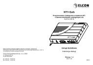
1 Short description of <strong>NT2MSKU</strong>-T/ continuation<br />
View of the casing with its elements<br />
LED display<br />
Legend film<br />
Upper casing part<br />
Casing bottom part<br />
Cramp foot for opening the casing<br />
Fig 1: View of the casing<br />
<strong>NT2MSKU</strong>-T <strong>NT2MSKU</strong>-T<br />
8 Mounting/Installation of <strong>NT2MSKU</strong>-T<br />
The <strong>NT2MSKU</strong>-T can be used as wallmounted or desktop device.<br />
Do not install the device in the vicinity of high electromagnetic fields (e.g. near loudspeakers,<br />
television sets etc.), since such sources of radiation and interference may affect the range<br />
of transmission. The mounting site should not be exposed to direct sun radiation and heat<br />
sources, but shall be kept dry and, if possible, dust-free.<br />
When using the device as desktop unit, the installation surface should be plain and dry.<br />
For mounting the device to the wall, the predetermined casing cut-outs (keyholes) shall be<br />
used, through which the device shall be mounted tension-free by screws 3 × 35 and dowels 6<br />
mm. Upon placing the dowels, attention shall be paid to wirings which may be concealed.<br />
The device is ready for operation after the signal cables are connected.<br />
For putting the <strong>NT2MSKU</strong>-T into operation, supply voltage must be provided. This is<br />
indicated by the green LED going on. Promptly upon provision of the supply voltage the<br />
<strong>NT2MSKU</strong>-T starts initialization which takes some seconds. This condition is signalled by<br />
flashing of LED UKS.<br />
Version: 2004/04/19 Version: 2004/04/19<br />
4 21
7 Mounting of remote power-supply module / continuation<br />
- Press upper part against bottom part (4 × audible clicking-in)<br />
- Now place the cramp feet (paying attention to the cut-outs for wallmounting)<br />
Fig. 19: Placing the upper casing part<br />
<strong>NT2MSKU</strong>-T <strong>NT2MSKU</strong>-T<br />
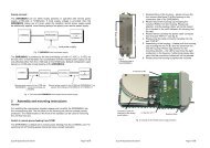
2 Interfaces at <strong>NT2MSKU</strong>-T<br />
All interfaces of the <strong>NT2MSKU</strong>-T are placed on the rear side of the device.<br />
UB-power<br />
supply<br />
T3ab<br />
FPE<br />
UKS (RJ45)<br />
UKS (Wago<br />
Cage-Clamp)<br />
S2M (RJ45)<br />
S2Man / S2Mab<br />
Switch Operation / Service<br />
Figure 2: Rear side showing the interfaces<br />
Version: 2004/04/19 Version: 2004/04/19<br />
20 5
2 Interfaces at the <strong>NT2MSKU</strong>-T/ continuation<br />
The various interfaces have below functions and assignment:<br />
UKS interface (RJ 45)<br />
The UKS interface is responsible for matching to the SHDSL interface. Basically, the interface<br />
wiring consists of an SHDSL transceiver with accompanying line interface and overvoltage<br />
protection. From physical point of view, the interface is an RJ 45 jack or, alternatively,<br />
a Wago Cage-Clamp connector. The interfaces have below functions and assignment:<br />
Fig. 3: UKS interface<br />
UKS interface (Wago Cage-Clamp connector)<br />
1 2 3 4 5 6<br />
Fig. 4: Wago Cage-Clamp interface<br />
1 UKSa<br />
2 UKSb<br />
3 not used<br />
4 not used<br />
5 not used<br />
6 to 8 not used<br />
1 FPE<br />
2 not used<br />
3 not used<br />
4 UKSa<br />
5 UKSb<br />
6 FPE<br />
Safety precautions: If the UKS interface is linked through the Western jack (RJ45<br />
socket, fig. 3), make sure the 6-pole multiple socket connector is<br />
plugged onto the Wago Cage-Clamp connector of the UKS interface<br />
(see fig. 4) and screwed on, since in case of linking the UKS<br />
port via the Western jack (RJ45 socket) there is danger of touching<br />
the contacts of the UKS-Wago Cage-Clamp connector.<br />
<strong>NT2MSKU</strong>-T <strong>NT2MSKU</strong>-T<br />
7 Mounting of remote power-supply module / continuation<br />
- Place upper part (keeping it inclined) on the film and then set it onto the casing<br />
bottom part<br />
Fig. 18: Closing the casing<br />
Version: 2004/04/19 Version: 2004/04/19<br />
6 19
7 Mounting of remote power-supply module / continuation<br />
9. Mount the device as follows:<br />
- Insert legend film into the casing´s bottom part<br />
- Make sure that LED domes are duly seated<br />
Fig. 17: Inserting the front panel<br />
<strong>NT2MSKU</strong>-T <strong>NT2MSKU</strong>-T<br />
2 Interfaces at <strong>NT2MSKU</strong>-T/ continuation<br />
S2M interface<br />
The S2M interface represents the subscriber port according to normative 1 TR 237. In the<br />
main, the S2M interface wiring comprises components for overvoltage protection on the<br />
input and output, a transceiver and a framer. From physical point of view, the interface is an<br />
RJ 45 jack. For measuring and test purposes, the operating mode "Measurement" can be<br />
chosen by a switch on the back.<br />
T3ab interface for clock-pulse output<br />
Fig. 5: S2M interface<br />
1 S2Mab/a<br />
2 S2Mab/b<br />
3 not used<br />
4 S2Man/a<br />
5 S2Man/b<br />
6 to 8 not used<br />
The symmetric interface is galvanically separated from the circuitry. Under the condition of<br />
faultless operation, the interface allows to extract the timing signal recovered from the received<br />
signal UKSan. The clock pulse consists of a 2,048 kHz signal with a clock-pulse ratio<br />
of 1:1.<br />
Fig. 6: Interface T3ab<br />
1 T3ab/a<br />
2 T3ab/b<br />
3 to 8 not used<br />
Version: 2004/04/19 Version: 2004/04/19<br />
18 7
2 Interfaces at <strong>NT2MSKU</strong>-T/ continuation<br />
UB Power supply interface<br />
This interface has been designed in compliance with regulation 1 TR216. The interface is<br />
short-circuit-proof, so that polarity reversal would not cause damage to the device. Thanks to<br />
the Wago Cage-Clamp connector, unintentional change of polarity is actually impossible.<br />
The supply voltage range goes from -20 V to -75 V.<br />
FPE may also be screwed on the earthing screw.<br />
Fig. 7: UB interface<br />
1 +UB<br />
2 FPE<br />
3 -UB<br />
If for local power supply of the <strong>NT2MSKU</strong>-T the used power pack differs from the specified<br />
one (e.g. older two-pole units lacking of FPE- / earth conductor), the <strong>NT2MSKU</strong>-T needs<br />
additional grounding. Duly earthing shall be effected through one of the following two options<br />
(→ Fig. 8):<br />
1. Earthing connection to the central contact of the Wago Cage-Clamp connector at<br />
the UB power supply interface (rear side of the device)<br />
2. Earthing connection to the earthing screw FPE (on the device´s rear side)<br />
1 2<br />
Fig. 8: Rear side of the device - Additional earthing connection<br />
<strong>NT2MSKU</strong>-T <strong>NT2MSKU</strong>-T<br />
7 Mounting of remote power-supply module / continuation<br />
Fig. 16: Mounting of the FSP module<br />
- Fix the module by means of two screws (contained in bag with accessories).<br />
Version: 2004/04/19 Version: 2004/04/19<br />
8 17
7 Mounting of remote power-supply module / continuation<br />
8. The remote power-supply module shall be mounted according to below figures:<br />
Fig. 15: Module FSP as separate sub-unit<br />
<strong>NT2MSKU</strong>-T <strong>NT2MSKU</strong>-T<br />
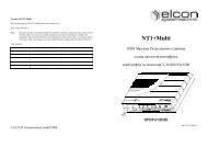
3 Block diagram<br />
E1<br />
Framer<br />
&<br />
E1 Transceiver<br />
Bild 9: Block diagram <strong>NT2MSKU</strong>-T<br />
Version: 2004/04/19 Version: 2004/04/19<br />
16 9<br />
UB<br />
S2M<br />
G.703<br />
Power pack<br />
DC/DC<br />
EMC<br />
Controller &<br />
Peripheral<br />
1 ... 8<br />
SHDSL<br />
Framer<br />
SHDSL<br />
Transceiver<br />
Line<br />
interface<br />
EMC<br />
UKS
4 Display elements<br />
On the <strong>NT2MSKU</strong>-T front panel, there are 5 light-emitting diodes (LED) that indicate the<br />
various operating modes. Their meaning is given in the table below:<br />
Meaning EIN S2M E1 UKS FSP<br />
Normal mode (without FSP or FSP<br />
switched off)<br />
ON OFF OFF OFF OFF<br />
Normal mode (with activated FSP) ON OFF OFF OFF ON<br />
Error in remote supply unit **<br />
(for operation with FSP)<br />
1 Hz<br />
S2M Urgent alarm at S2Man<br />
(LOS/BER3/LOF)<br />
ON<br />
AIS at S2Man (in unstructuured mode) 4 Hz<br />
SHDSL Urgent alarm at UKSan<br />
(LOS/LOF SHDSL)<br />
OFF ON<br />
LOF/BER-3 at UKSan (PDH) ON OFF<br />
AIS at UKSan (PDH) 4 Hz OFF<br />
tuAIS at UKSan (SDH) 4 Hz 4 Hz<br />
tuLOP (Loss of Pointer) (SDH) 4 Hz 4 Hz<br />
SHDSL startup* OFF 1 Hz<br />
Explanation of symbols:<br />
* flashes until SHDSL is established<br />
** e.g. overvoltage, overcurrent, unbalance or line interruption<br />
ON LED shines permanently<br />
OFF LED does not shine<br />
1 Hz LED flashes at 1 Hz<br />
4 Hz LED flashes at 4 Hz<br />
Table 1: Meaning of LED displays<br />
<strong>NT2MSKU</strong>-T <strong>NT2MSKU</strong>-T<br />
7 Mounting of remote power-supply module / continuation<br />
7. Remove cover plate.<br />
Fig. 14: Circuit board of <strong>NT2MSKU</strong>-T<br />
Version: 2004/04/19 Version: 2004/04/19<br />
10 15
7 Mounting of remote power-supply module / continuation<br />
3. Insert a screw-sriver (size 4-5) into those holes of the casing that are not<br />
marked with the crossed-out screw-driver symbol and slightly tilt it outside<br />
(2×)<br />
4. The casing snaps open on one side.<br />
5. Relocate the device with upper part now showing to the top.<br />
6. Unlocking procedure as described in point 3.<br />
Fig. 13: Unlocking the casing<br />
<strong>NT2MSKU</strong>-T <strong>NT2MSKU</strong>-T<br />
5 Operating elements<br />
A switch on the rear side of the <strong>NT2MSKU</strong>-T allows switching between normal mode and<br />
test mode. If the switch is set on Operation, the S2M interface signals can be checked by<br />
high-impedance activation of a respective measuring instrument. When the switch is set on<br />
Measurement, the signal path is separated so that external test signals can be fed in.<br />
Pin assignment of test socket / splitting jack S2M<br />
Device side Client side<br />
14 11<br />
Version: 2004/04/19 Version: 2004/04/19<br />
Switch<br />
Device side Client side<br />
Switch<br />
Fig. 10: Test- / Splitting jack S2M (on device rear side)<br />
Operation<br />
Measurement
6 Remote power-supply module FSP2M<br />
The remote power-supply module is optionally available and can be used for powering of an<br />
NT-side regenerative repeater.<br />
The module is designed as plug-in unit and is being mounted to the main unit of the<br />
<strong>NT2MSKU</strong>-T by means of DIN connectors (cf. chapter "Mounting of remote power-supply<br />
module). Two screws are needed for fixing the FSP2M.<br />
Power supply voltages<br />
provided by the basic<br />
module<br />
Energy<br />
buffer<br />
Fig. 11: Block diagram of FSP module<br />
<strong>NT2MSKU</strong>-T <strong>NT2MSKU</strong>-T<br />
Regulator<br />
Regulator<br />
Remote<br />
power<br />
supply<br />
channel 1<br />
Remote<br />
power<br />
supply<br />
channel 1<br />
Main<br />
processor<br />
7 Mounting of remote power-supply module<br />
The optional remote power-supply module is mounted to the basis unit by means of DIN<br />
connectors. This operation requires opening of the device. For this, proceed as follows:<br />
1. Put the <strong>NT2MSKU</strong>-T upside down.<br />
2. Remove cramp feet.<br />
Fig.12: Removing the cramp feet<br />
Version: 2004/04/19 Version: 2004/04/19<br />
12 13