PDF Download - Glidewell Dental Labs
PDF Download - Glidewell Dental Labs
PDF Download - Glidewell Dental Labs

Create successful ePaper yourself
Turn your PDF publications into a flip-book with our unique Google optimized e-Paper software.
Conventional implant planning typically involves the use<br />
of a periapical radiograph (PA) and/or a panoramic film.<br />
The drawback to these types of two-dimensional images is<br />
distortion. The PA should be taken with a paralleling technique<br />
to avoid vertical distortion as much as possible. A<br />
radiographic marker of known diameter (e.g., 5 mm ball<br />
bearing) can be used to determine the distortion in the<br />
planned implant site. The marker is measured on the film<br />
to determine the distortion factor in that area. A transparent<br />
overlay can be used as an aid to determine the correct<br />
implant selection (Fig. 1).<br />
Another option is a CT scan. Cone beam scanners provide a<br />
three-dimensional image and a precise method for identification<br />
of the IAN. 8 The patient’s scan can be imported into<br />
planning software, the mandibular canal identified, and the<br />
implant placed in a virtual environment (Fig. 2).<br />
In the case presented here, the canal was well differentiated<br />
and identified. The mandibular canal is typically identifiable.<br />
However, there are situations where the cortical bone<br />
surrounding the canal is not dense and therefore does not<br />
show up radiographically. These cases present a significant<br />
challenge. One rule of thumb for first molars is to not drill<br />
deeper than the roots of the adjacent teeth.<br />
An optical scan of the model provides a clear view of<br />
the anatomy of the teeth and the soft tissue (Fig. 3). The<br />
appropriate-sized implant is placed within the confines of<br />
the available bone (Fig. 4). It is important to be aware that the<br />
drills are approximately 1 mm longer than the stated length<br />
of the implant. The trajectory of the implant is aimed toward<br />
the opposing stamp cusp through the center of the<br />
occlusal table.<br />
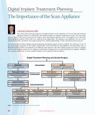
Figure 1: Implant radiographic template for Inclusive Tapered Implants<br />
Figure 2: Digital Treatment Plan<br />
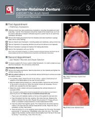
Surgery<br />
The osteotomy should be prepared with the aid of a<br />
surgical or prosthetic guide. The prosthetic component of<br />
the Inclusive ® Tooth Replacement Solution is a traditional<br />
surgical stent designed to convey the ideal position of the<br />
implant platform from the restorative perspective (Figs. 5, 6).<br />
By starting the osteotomy using this guide, the implant will<br />
be inserted in the appropriate location to take advantage of<br />
the custom temporary abutment and BioTemps ® provisional<br />
crown. The prosthetic guide is intended for prosthetic<br />
reference only, and does not take into consideration any<br />
anatomical landmarks or contraindications. This guide<br />
should be used in combination with the radiographic and<br />
clinical information to determine the best position for<br />
the implant.<br />
Figure 3: View of mandibular arch with proposed implant trajectory<br />
A surgical guide based on the virtual plan utilizing a CBCT<br />
scan of the patient provides the option of drill depth and<br />
angulation control. Based on the amount of guidance<br />
desired, a surgical guide can be produced that guides the<br />
pilot drill. Subsequent drilling with progressively wider<br />
20<br />
– www.inclusivemagazine.com –