PDF Download - Glidewell Dental Labs
PDF Download - Glidewell Dental Labs
PDF Download - Glidewell Dental Labs

Create successful ePaper yourself
Turn your PDF publications into a flip-book with our unique Google optimized e-Paper software.
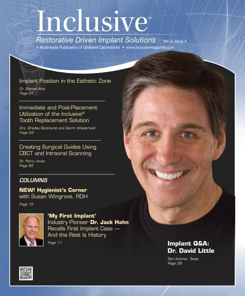
Inclusive<br />
Restorative Driven Implant Solutions Vol. 3, Issue 3<br />
A Multimedia Publication of <strong>Glidewell</strong> Laboratories • www.inclusivemagazine.com<br />
Implant Position in the Esthetic Zone<br />
Dr. Siamak Abai<br />
Page 27<br />
Immediate and Post-Placement<br />
Utilization of the Inclusive ®<br />
Tooth Replacement Solution<br />
Drs. Bradley Bockhorst and Darrin Wiederhold<br />
Page 53<br />
Creating Surgical Guides Using<br />
CBCT and Intraoral Scanning<br />
Dr. Perry Jones<br />
Page 83<br />
COLUMNS<br />
NEW! Hygienist’s Corner<br />
with Susan Wingrove, RDH<br />
Page 15<br />
‘My First Implant’<br />
Industry Pioneer Dr. Jack Hahn<br />
Recalls First Implant Case —<br />
And the Rest Is History<br />
Page 11<br />
Implant Q&A:<br />
Dr. David Little<br />
San Antonio, Texas<br />
Page 39
On the Web<br />
Here’s a sneak peek at additional<br />
Inclusive magazine content available online<br />
ONLINE Video Presentations<br />
■ Dr. Bradley Bockhorst details the process by which the Inclusive ®<br />
Tooth Replacement Solution can be used to efficiently and predictably<br />
restore a missing mandibular molar.<br />
■ Dr. Siamak Abai outlines spatial and angular considerations for the<br />
optimal placement of dental implants in the esthetic zone.<br />
■ Dr. David Little discusses some of the exciting services made possible<br />
by cutting-edge dental technologies, emphasizing the beneficial<br />
nature of personalized diagnoses and treatments.<br />
■ Dr. Michael DiTolla illustrates the use of a lab-fabricated verifi cation<br />
jig to obtain an accurate occlusal relationship in distal free-end cases.<br />
■ <strong>Glidewell</strong> Laboratories unveils the Open Platform Inclusive Tooth<br />
Replacement Solution, expanding this revolutionary treatment package<br />
to accommodate other popular implant brands.<br />
■ Drs. Darrin Wiederhold and Bradley Bockhorst demonstrate the<br />
clinician’s option with the Inclusive Tooth Replacement Solution to<br />
immediately temporize an implant with custom healing components<br />
or to provide patient-specific temporization post-implant placement.<br />
■ Dzevad Ceranic, CDT, and <strong>Glidewell</strong> staff showcase the advantages,<br />
increasing popularity, and industry-leading quality of Inclusive ®<br />
Custom Abutments.<br />
Check out the latest issue of Inclusive<br />
magazine online or via your smartphone<br />
at www.inclusivemagazine.com<br />
■ Dr. Christopher Travis reviews the symptoms, causes, and treatment<br />
of dry mouth, promoting implant-borne restorations as a solution<br />
for the partially or fully edentulous xerostomia patient.<br />
■ Dr. Perry Jones highlights the merging of CBCT and intraoral<br />
scanning technology to create precise surgical guides for safer,<br />
more predictable implant surgeries.<br />
Look for these icons on the pages that follow<br />
for additional content available online<br />
ONLINE CE credit<br />
■ Get free CE credit for the material in this issue with each test you<br />
complete and pass. To get started, visit our website and look for<br />
the articles marked with “CE.”<br />
– www.inclusivemagazine.com –
Contents<br />
19<br />
Restoring Mandibular Single Teeth with the<br />
Inclusive Tooth Replacement Solution<br />
The replacement of missing mandibular molars with single-tooth,<br />
implant-borne restorations provides many benefits over fixed partial<br />
dentures, and is by far the most common indication for implant treatment,<br />
according to laboratory statistics. Dr. Bradley Bockhorst offers<br />
a detailed walkthrough of the process by which the Inclusive Tooth<br />
Replacement Solution can be used to simplify the restorative process<br />
and provide a predictable outcome for this common restoration.<br />
27<br />
Implant Position in the Esthetic Zone<br />
Proper implant positioning is patient- and quite often implant-specific,<br />
making prosthetic treatment planning and pre-placement protocol<br />
paramount for achieving predictable restorative results. Dr. Siamak<br />
Abai, staff dentist of clinical research at <strong>Glidewell</strong> Laboratories, details<br />
some of the established parameters with regard to implant spacing and<br />
angulation, and highlights the use of advanced tools such as Inclusive<br />
Digital Treatment Planning services and the Inclusive Tooth Replacement<br />
Solution to execute precise control over each individual case.<br />
39<br />
Implant Q&A: An Interview with Dr. David Little<br />
In this interview, a Texas-sized passion for excellence and commitment<br />
to improving quality of life for edentulous patients comes through as<br />
Dr. David Little weighs in on several aspects of what makes today’s<br />
progressive dental practice a success. Find out what this general dentist<br />
has to say on topics ranging from building a truly interdisciplinary<br />
practice, to incorporating advanced technologies, to educating the<br />
entire team, to treatment planning for patients as if they were family.<br />
53<br />
Photo Essay: Immediate and Post-Placement<br />
Utilization of the Inclusive Tooth Replacement Solution<br />
The Inclusive Tooth Replacement Solution enables clinicians to<br />
place and immediately temporize single-unit implants in edentulous<br />
spaces. It can also be used in cases where the implant has already<br />
been placed. With a pair of case reports, Drs. Darrin Wiederhold<br />
and Bradley Bockhorst illustrate the simplified, predictable process<br />
by which this versatile, one-of-a-kind solution addresses implant<br />
placement and soft tissue healing in a manner that will help pave<br />
the path to a superior final restoration.<br />
– Contents – 1
Contents<br />
75<br />
83<br />
91<br />
Treating Xerostomia Patients:<br />
A Clinical Conversation with Dr. Christopher Travis<br />
Dentists are often the first to identify patients who are experiencing<br />
the effects of xerostomia, or dry mouth. Here, Dr. Christopher<br />
Travis offers a brief refresher on oral anatomy and the major sets<br />
of salivary glands as he explores the symptoms, causes, treatment<br />
options, and advantages of dental implants for xerostomia patients.<br />
Implant prostheses can provide a good solution for these patients.<br />
Creating Surgical Guides Using CBCT and<br />
Intraoral Scanning<br />
Among recent advances in the use of Align Technology’s iTero <br />
optical scanner is the ability to merge its generic STL files<br />
directly with CBCT DICOM files to allow for the creation of very<br />
precise, tooth-borne surgical guides. In this clinical case report,<br />
Dr. Perry Jones showcases the use of oral scanning technology to<br />
plan implant placement, create a precise surgical guide in a virtual<br />
environment, place implant fixtures, and restore those implants —<br />
all without the use of a conventional analog model.<br />
“Rules of 10” — Guidelines for Successful<br />
Planning and Treatment of Mandibular Edentulism<br />
Using <strong>Dental</strong> Implants<br />
The three “Rules of 10” for treatment planning dental implant therapy<br />
in the edentulous mandible are designed to improve the success<br />
of both endosseous implants and the prosthesis. These so-called<br />
rules acknowledge and provide a method to control the mechanical<br />
environment, addressing factors affecting implant and prosthesis<br />
longevity. Dr. Lyndon Cooper, et al., outline and provide support<br />
for these rules, then illustrate their application in the treatment of<br />
mandibular edentulism.<br />
ALSO IN THIS ISSUE<br />
8 Trends in Implant Dentistry<br />
Average Number of Implants per Case<br />
11 My First Implant<br />
Dr. Jack Hahn<br />
15 Hygienist’s Corner<br />
A Probing Question<br />
31 Small Diameter Implants<br />
Planning from the<br />
Prosthetic Perspective<br />
35 Clinical Tip<br />
Bone Quality Based Drilling<br />
Protocol: Achieving High<br />
Primary Stability<br />
47 Product Spotlight<br />
Inclusive Tooth Replacement<br />
Solution: Open Platform<br />
49 Clinical Tip<br />
Obtaining Accurate Occlusal Records<br />
in Kennedy Class I and Class II<br />
Implant Cases<br />
65 Clinical Tip<br />
When a Flapless Approach<br />
Makes Sense<br />
67 Lab Sense<br />
Best in Class: Inclusive<br />
Custom Abutments<br />
2<br />
– www.inclusivemagazine.com –
Publisher<br />
Jim <strong>Glidewell</strong>, CDT<br />
Editor-in-Chief and clinical editor<br />
Bradley C. Bockhorst, DMD<br />
Managing Editors<br />
David Casper, Jennifer Holstein, Barbara Young<br />
Creative Director<br />
Rachel Pacillas<br />
Contributing editors<br />
Greg Minzenmayer; Dzevad Ceranic, CDT;<br />
Eldon Thompson<br />
copy editors<br />
David Frickman, Megan Strong<br />
digital marketing manager<br />
Kevin Keithley<br />
Graphic Designers/Web Designers<br />
Emily Arata, Jamie Austin, Deb Evans,<br />
Kevin Greene, Joel Guerra, Audrey Kame,<br />
Phil Nguyen, Kelley Pelton, Melanie Solis,<br />
Ty Tran, Makara You<br />
Photographers/Videographers<br />
Sharon Dowd, Mariela Lopez,<br />
James Kwasniewski, Andrew Lee,<br />
Marc Repaire, Sterling Wright, Maurice Wyble<br />
Illustrator<br />
Phil Nguyen<br />
coordinatorS/AD Representatives<br />
Teri Arthur, Vivian Tsang<br />
If you have questions, comments or suggestions, e-mail us at<br />
inclusivemagazine@glidewelldental.com. Your comments may<br />
be featured in an upcoming issue or on our website.<br />
© 2012 <strong>Glidewell</strong> Laboratories<br />
Neither Inclusive magazine nor any employees involved in its publication<br />
(“publisher”) makes any warranty, express or implied, or assumes<br />
any liability or responsibility for the accuracy, completeness, or usefulness<br />
of any information, apparatus, product, or process disclosed, or<br />
represents that its use would not infringe proprietary rights. Reference<br />
herein to any specific commercial products, process, or services by<br />
trade name, trademark, manufacturer or otherwise does not necessarily<br />
constitute or imply its endorsement, recommendation, or favoring<br />
by the publisher. The views and opinions of authors expressed<br />
herein do not necessarily state or reflect those of the publisher and<br />
shall not be used for advertising or product endorsement purposes.<br />
CAUTION: When viewing the techniques, procedures, theories and<br />
materials that are presented, you must make your own decisions<br />
about specific treatment for patients and exercise personal professional<br />
judgment regarding the need for further clinical testing or education<br />
and your own clinical expertise before trying to implement new<br />
procedures.<br />
Inclusive is a registered trademark of Inclusive <strong>Dental</strong> Solutions.<br />
4<br />
– www.inclusivemagazine.com –
Letter from the Editor<br />
There are many axioms used in implantology, such as, “begin with the end<br />
in mind” and “implant dentistry is a restorative procedure with a surgical<br />
component,” all pointing to the importance of proper diagnosis and case<br />
work-up. Addressing this topic we have: an article on implant planning<br />
in the esthetic zone, penned by our own Dr. Siamak Abai; an interview<br />
with Dr. David Little, where we look at treating the edentulous patient;<br />
and, because treatment planning should be considered not just from the<br />
surgical perspective but from the prosthetic aspect as well, we’ve included<br />
an informative article by Dr. Lyndon Cooper, et al., with guidelines for<br />
restoring edentulous mandibles. Our Small Diameter Implants column<br />
reviews the importance of planning from the prosthetic perspective for<br />
overdenture cases.<br />
As you’ve seen in the last few issues, the Inclusive ® Tooth Replacement<br />
Solution has the potential to change the way implant dentistry is practiced.<br />
We are pleased to announce the expansion of this comprehensive solution<br />
for other major implant platforms, as well as post-placement utilization<br />
of its patient-specific components. For more on this topic, check out our<br />
product spotlight (page 47) and photo essay (page 53).<br />
In our My First Implant column, we feature one of implant dentistry’s<br />
pioneers, Dr. Jack Hahn, who takes us back to 1969 — when another<br />
revolution entirely was taking place. We are confident you’ll enjoy this<br />
retrospective from a clinician who has made major contributions to<br />
implantology. We are also introducing a new column that will focus on a<br />
very critical aspect of implant dentistry: the role of the dental hygienist.<br />
Susan Wingrove, RDH, skillfully kicks off the Hygienist’s Corner with her<br />
discussion of evaluating implants at the recall appointment.<br />
These are exciting times. The field of implant dentistry is rapidly advancing,<br />
and we are committed to keeping you up to date with new technologies<br />
and procedures as we continue to provide easy, convenient, and<br />
affordable solutions for you and your patients.<br />
Wishing you continued success,<br />
Dr. Bradley C. Bockhorst<br />
Editor-in-Chief, Clinical Editor<br />
inclusivemagazine@glidewelldental.com<br />
– Letter from the Editor – 5
Contributors<br />
■ Bradley C. Bockhorst, DMD<br />
After receiving his dental degree from<br />
Washington University School of <strong>Dental</strong><br />
Medicine, Dr. Bradley Bockhorst served<br />
as a Navy <strong>Dental</strong> Officer. Dr. Bockhorst is<br />
director of clinical technologies at <strong>Glidewell</strong><br />
Laboratories, where he oversees Inclusive ®<br />
Digital Implant Treatment Planning services<br />
and is editor-in-chief and clinical editor of Inclusive<br />
magazine. A member of the CDA, ADA, AO, ICOI and the<br />
AAID, Dr. Bockhorst lectures internationally on an array<br />
of dental implant topics. Contact him at 800-521-0576 or<br />
inclusivemagazine@glidewelldental.com.<br />
■ DZEVAD CERANIC, CDT<br />
Dzevad Ceranic began his career at <strong>Glidewell</strong><br />
Laboratories while attending Pasadena<br />
City College’s dental laboratory technology<br />
program. In 1999, Dzevad began working at<br />
<strong>Glidewell</strong> as a waxer and metal finisher, then<br />
as a ceramist. He was then promoted to general<br />
manager of the Full-Cast department. In 2008,<br />
Dzevad took on the company’s rapidly growing Implant department,<br />
and in 2009 completed an eight-month implants course<br />
at UCLA School of Dentistry. Today, Dzevad leads an implant<br />
team of more than 250 employees at the lab. Contact him at<br />
inclusivemagazine@glidewelldental.com.<br />
■ SIAMAK ABAI, DDS, MMedSc<br />
Dr. Siamak Abai earned his DDS degree from<br />
Columbia University in 2004, followed by<br />
two years of residency in general dentistry.<br />
After two years of general private practice in<br />
Huntington Beach, Calif., Dr. Abai returned<br />
to academia and received an MMedSc degree<br />
and a certificate in prosthodontics from<br />
Harvard University. Before joining <strong>Glidewell</strong> in January<br />
2012, he practiced at the Wöhrle <strong>Dental</strong> Implant Clinic in<br />
Newport Beach. Dr. Abai brings nearly 10 years of clinical,<br />
research, and lecturing experience to his role as staff dentist<br />
of clinical research at <strong>Glidewell</strong> Laboratories. Contact him at<br />
inclusivemagazine@glidewelldental.com.<br />
■ LYNDON F. COOPER, DDS, Ph.D<br />
Dr. Lyndon Cooper serves as a professor<br />
and current chair of the University of North<br />
Carolina at Chapel Hill School of Dentistry<br />
Department of Prosthodontics and has an<br />
adjunct appointment at the UNC School of<br />
Medicine. Dr. Cooper is also director of the<br />
graduate prosthodontics program and the<br />
Bone Biology and Implant Therapy Laboratory. He is a<br />
Diplomate of the American Board of Prosthodontics and<br />
current president of the American College of Prosthodontics<br />
Board of Directors. His lab’s research findings have been<br />
presented in more than 70 publications. Contact him at<br />
lyndon_cooper@dentistry.unc.edu.<br />
■ GRANT BULLIS, MBA<br />
Grant Bullis, director of implant R&D and<br />
digital manufacturing at <strong>Glidewell</strong> Laboratories,<br />
began his dental industry career at<br />
Steri-Oss (now a subsidiary of Nobel Biocare)<br />
in 1997. Since joining the lab in 2007,<br />
Grant has been integral in obtaining FDA<br />
510(k) clearances for the company’s Inclusive<br />
® Custom Implant Abutments. In 2010, he was promoted<br />
to director and now oversees all aspects of CAD/CAM, implant<br />
product development, and manufacturing. Grant has<br />
a degree in mechanical CAD/CAM from Irvine Valley College<br />
and an MBA from Keller Graduate School of Management.<br />
Contact him at inclusivemagazine@glidewelldental.com.<br />
■ JACK A. HAHN, DDS<br />
Dr. Jack Hahn earned his DDS from Ohio State<br />
University College of Dentistry, and completed<br />
postgraduate coursework at Boston University,<br />
New York University, the University of Michigan<br />
and the University of Kentucky. A pioneer in the<br />
field who developed the NobelReplace ® dental<br />
implant system for Nobel Biocare, Dr. Hahn<br />
has been actively involved in placing and restoring implants for<br />
40 years. In addition to lecturing to dentists around the world,<br />
he maintains a private practice in Cincinnati, Ohio, focused<br />
on placing and restoring implants. In 2004, he received the<br />
Aaron Gershkoff Lifetime Achievement Award in implant<br />
dentistry. Contact him at replace7@mac.com.<br />
6<br />
– www.inclusivemagazine.com –
■ PERRY E. JONES, DDS, FAGD<br />
Dr. Perry Jones received his DDS from<br />
Virginia Commonwealth University School of<br />
Dentistry, where he has held adjunct faculty<br />
positions since 1976. He maintains a private<br />
practice in Richmond, Va. One of the first GP<br />
Invisalign ® providers, Dr. Jones has been a<br />
member of Align’s Speaker Team since 2002,<br />
presenting more than 250 Invisalign presentations. He has<br />
been involved with CADENT optical scanning technology<br />
since its release to the GP market and is currently beta<br />
testing its newest software. Dr. Jones belongs to numerous<br />
dental associations and is a fellow of the AGD. Contact him<br />
at perry@drperryjones.com.<br />
■ CHRISTOPHER P. TRAVIS, DDS<br />
Dr. Christopher Travis received his dental<br />
degree and certificate in prosthodontics from<br />
USC School of Dentistry, where he served as an<br />
assistant clinical professor in predoctoral and<br />
graduate prosthodontics. For the past 30 years,<br />
he has maintained a full-time private practice<br />
specializing in prosthodontics in Laguna<br />
Hills, Calif. Dr. Travis is director of the Charles Stuart Study<br />
Group in Laguna Hills, prosthodontic coordinator for the<br />
Newport Harbor Academy of Dentistry and active member of<br />
the Pacific Coast Society for Prosthodontics, American College<br />
of Prosthodontists and AO, as well as a Fellow of the ACD.<br />
Contact him at 949-683-7456 or surfnswim@fea.net.<br />
■ DAVID A. LITTLE, DDS<br />
Dr. David Little received his DDS at the University<br />
of Texas Health Science Center at San<br />
Antonio <strong>Dental</strong> School and now maintains a<br />
multidisciplinary, state-of-the-art dental practice<br />
in San Antonio, Texas. An accomplished<br />
national and international speaker, professor,<br />
and author, he also serves the dental profession<br />
as a clinical researcher focusing on implants, laser surgery,<br />
and dental materials. As a professional consultant, he shares<br />
his expertise on emerging restorative techniques and materials<br />
with industry peers. Highly respected for his proficiency in<br />
team motivation, Dr. Little’s vision, leadership, and experience<br />
are recognized worldwide. Contact him at dlittledds@aol.com.<br />
■ DARRIN M. WIEDERHOLD, DMD, MS<br />
Dr. Darrin Wiederhold received his DMD<br />
in 1997 from Temple University School of<br />
Dentistry and a master’s degree in oral<br />
biology in 2006 from Medical University<br />
of Ohio at Toledo. He has worked in several<br />
private practices, and as a staff dentist for<br />
the U.S. Navy and the <strong>Glidewell</strong> Laboratories<br />
Implant department. While at <strong>Glidewell</strong>, he performed implant<br />
and conventional restorative procedures at the lab’s on-site<br />
training facility and helped support the lab’s digital treatment<br />
planning and guided surgery services. He is currently in private<br />
practice in San Diego, Calif. Contact him at 619-469-4144<br />
or DMWDMD97@hotmail.com.<br />
■ MICHAEL McCRACKEN, DDS, Ph.D<br />
After completing dental school at University of<br />
North Carolina at Chapel Hill and a prosthodontic<br />
residency at University of Alabama at<br />
Birmingham, Dr. Michael McCracken received<br />
a Ph.D in biomedical engineering for research<br />
related to growth factors and healing of implants<br />
in compromised hosts. Dr. McCracken is<br />
a professor in the department of general dental sciences at UAB<br />
School of Dentistry, where he has also served as associate dean<br />
for education, director of graduate prosthodontics, and director<br />
of the implant training program. He maintains an active<br />
research program within the university and a private practice<br />
focused on implant dentistry. He also lectures internationally.<br />
Contact him at inclusivemagazine@glidewelldental.com.<br />
■ SUSAN S. WINGROVE, RDH<br />
Susan Wingrove is a national and international<br />
speaker and practicing dental<br />
hygienist, who does regeneration research as<br />
a consultant for Regena Therapeutics and<br />
instrument design for Paradise <strong>Dental</strong> Technologies<br />
Inc. She designed the Wingrove<br />
Implant Series, ACE probes, and Queen of<br />
Hearts instruments. A member of the AO and The Implant<br />
Consortium (TIC), she is also a published author on implant<br />
dentistry who has written articles for Hygienetown and the<br />
British Society of <strong>Dental</strong> Hygiene and Therapy, as well as the<br />
textbook “Peri-Implant Therapy for the <strong>Dental</strong> Hygienist: A<br />
Clinical Guide to Implant Maintenance” (Wiley-Blackwell).<br />
Contact her at sswinrdh@gmail.com.<br />
– Contributors – 7
Trends in<br />
Implant Dentistry<br />
Average Number of Implants per Case<br />
With the large number of implant-borne cases fabricated at <strong>Glidewell</strong> Laboratories, certain<br />
evolving trends have come to light. Here are some stats about the number of implants that<br />
are being placed per case.<br />
1 Implant 2 Implants 3 Implants 4 Implants 5+ Implants<br />
Number of Implants per Case<br />
2010<br />
Number of Implants per Case<br />
2011<br />
71%<br />
75%<br />
3%<br />
3%<br />
7%<br />
16%<br />
1%<br />
1%<br />
4%<br />
19%<br />
Data Source: <strong>Glidewell</strong> Laboratories January 2010–August 2012<br />
8<br />
– www.inclusivemagazine.com –
In an evaluation of more than 70,000 cases,<br />
the average number of implants per case is<br />
Of all the cases we have processed<br />
over the last three years…<br />
1.43<br />
66%…were single teeth<br />
Number of Implants per Case<br />
2012 YTD<br />
Number of Implants per Case<br />
January 2010–August 2012<br />
60%<br />
69%<br />
1%<br />
1%<br />
24%<br />
14%<br />
1%<br />
2 % 11%<br />
17%<br />
Watch here for emerging trends<br />
Check back here for more observations in the next issue.<br />
– Trends in Implant Dentistry: Average Number of Implants per Case – 9
my first<br />
implant<br />
with Jack A. Hahn, DDS<br />
ack in the summer of 1969, against the<br />
backdrop of the cultural craziness that<br />
was the late sixties, there was another,<br />
quieter revolution taking place. Not man<br />
walking on the moon. Not the Beatles’ “Sgt. Pepper”<br />
album taking hold of a generation. But a sign of the<br />
times that technologies were changing the way we<br />
do things across professions, including the field of<br />
dentistry. Here, Dr. Jack Hahn recalls placing his<br />
first implant, an experience that would set the<br />
course for the rest of his professional life — and<br />
the lives of his future patients.<br />
– My First Implant: Dr. Jack Hahn – 11
We’ve Come a Long Way<br />
From subperiosteal implants…<br />
...to combined root-form and blade implants…<br />
...to the modern endosseous designs and CAD/CAM restorations of today.<br />
I got interested in implants when a patient<br />
came into my office one summer, decades ago, holding a<br />
shoebox that contained no less than 17 sets of dentures. She<br />
had a severely atrophic mandible that made it impossible<br />
to retain a mandibular conventional denture — and she<br />
was an emotional wreck. Her husband, who was a wellrespected<br />
orthopedic surgeon, explained that she was a<br />
dental cripple and that this condition had all but destroyed<br />
their social lives. They declined invitations to parties and<br />
avoided going out in public because she couldn’t wear her<br />
lower teeth. So sad. At the time I didn’t think there was any<br />
hope, and I told her so. (But the seed was planted.)<br />
Then, I ran into her husband at a hospital function. He’d<br />
since read about dental implants in an orthopedic journal,<br />
but I told him those things didn’t work. “There is infection<br />
and rejection.” That’s what we were told in school. In short,<br />
I gave them no solution or possibility for a better quality<br />
of life. I saw the husband yet again about five months later<br />
at a hospital meeting. He had since taken his wife to New<br />
York, and a Dr. Linkow had placed a subperiosteal implant<br />
that changed their lives. She could eat anything. They were<br />
able to go out in public again. And her self-confidence improved<br />
significantly. He said to me, “Implant dentistry is<br />
the future,” and that I should learn all about it — or get left<br />
behind. This advice, coming from an orthopedic surgeon,<br />
was a wake-up call.<br />
In January of 1970, I went to New York to take Dr. Leonard<br />
Linkow’s course. It was two days with a hands-on portion<br />
where the participants placed an endosseous blade in a<br />
clear plastic model. In order to take the course, you had to<br />
12<br />
– www.inclusivemagazine.com –
The House that Jack Built<br />
Inspired by that first experience, Dr. Jack Hahn went<br />
on to develop implant techniques and devices known<br />
for their simple yet ingenious designs that are used<br />
around the world today.<br />
1977 Miter blade-form implants<br />
1979 Titanodont root-form implants<br />
1986 Steri-Oss root-form and blade implants<br />
1997<br />
NobelReplace ® Tapered implant<br />
(Nobel Biocare)<br />
I didn’t sleep the<br />
night before.<br />
Evolution in Immediate Function<br />
purchase the implant kit, which consisted of 12 one-piece<br />
blades, 700 XXL burs, depth gauge, mallet, pliers, and seating<br />
instrument. A channel was prepared, and the implants<br />
were malleted into place using the seating instruments. As<br />
the implants were one piece with an abutment portion,<br />
one or two of the anterior abutment teeth were prepared,<br />
and an immediate provisional restoration was placed for<br />
immediate function. Three to six weeks post-insertion,<br />
impressions were taken for the final restoration: basically,<br />
a fixed bridge.<br />
Two months after completing the course, my first potential<br />
implant patient was sitting in my office for a consultation.<br />
She was bilaterally edentulous from the second premolars<br />
in the posterior mandible back. Her partial denture was<br />
wrapped in Kleenex in her purse. She said: “I can’t wear<br />
this thing, and I hate it. I want something permanent.”<br />
I told her that I had just taken an implant course, that<br />
she would be my first patient, and that I didn’t know if<br />
the things I demonstrated to her on my model would last<br />
10 minutes or 10 years. But she had good height and width<br />
of bone, so it seemed to me to be an ideal case. I told her<br />
we could do one side first, see how it went, and do the<br />
other side a month later. I also told her that because it was<br />
my first implant, I wouldn’t charge her for the implant, only<br />
the fixed bridge. She said, “Let’s do it.”<br />
In March of that same year, we scheduled Irma from 1:30<br />
p.m. to 5 p.m. I didn’t sleep the night before. I kept going<br />
over in my mind the incision, reflection of the soft tissue,<br />
implant groove preparation, implant placement, suturing,<br />
and fabrication of the provisional restoration.<br />
– My First Implant: Dr. Jack Hahn – 13
Sage advice for doctors<br />
new to implants<br />
1<br />
Enroll in an introductory<br />
course. Get a feel for whether implant<br />
dentistry is right for you.<br />
2<br />
3<br />
Educate yourself by enrolling<br />
in multiple courses. If implant<br />
dentistry is something you want to<br />
pursue, take an adequate number<br />
of courses — and wait until you feel<br />
confident in doing implant procedures.<br />
Learn basic surgical<br />
techniques. Aside from identifying<br />
important anatomical structures,<br />
diagnosis, treatment planning,<br />
radiographic interpretation and basic<br />
implant prosthetic principles — it’s<br />
critical that you understand basic<br />
surgical techniques.<br />
Start with an ideal case. Look<br />
for cases that have a good level of<br />
height and width of bone. Also, you<br />
want anatomical safe regions, such<br />
as the anterior mandible and single<br />
tooth replacements in both arches,<br />
eliminating three-unit bridges.<br />
Implant dentistry<br />
changed my life,<br />
as well as the<br />
lives of thousands<br />
of my patients.<br />
I started the procedure at 1:30 p.m. and had the provisional<br />
cemented by 3:30 p.m. Everything went absolutely perfectly.<br />
I was so excited that I said to my partner, “I don’t<br />
want to do anything else.” Replacing what nature had taken<br />
away was, from that instant on, exactly what I wanted to<br />
do for the rest of my professional life. Four weeks later, I<br />
placed her final bridge and placed the other implant on the<br />
opposite side. I told her that I’d have to charge her for that<br />
one because now I was an expert. We both laughed. She<br />
hugged me and said that I changed her life. Irma passed<br />
away in October 2000, 30 years later, with her implants and<br />
bridge still functioning until the day she died.<br />
After that first time, I went on to place many implant<br />
restorations, all types and various systems, over the next<br />
42 years. I estimate that I have placed and restored more<br />
than 30,000 implants. IM<br />
14<br />
– www.inclusivemagazine.com –
Hygienist’s<br />
Corner<br />
A Probing Question<br />
with Susan S. Wingrove, RDH<br />
When assessing for peri-implant disease, “bleeding on<br />
probing” (BOP) is invaluable in the diagnostic process for<br />
peri-implant mucositis, and probing depths are valuable<br />
in assessing loss of bone support around osseointegrated<br />
implants. 1,2 An important yet controversial component of<br />
the assessment is probing the dental implant.<br />
Some implant surgeons recommend not probing the<br />
implant, or waiting three to six months following abutment<br />
attachment to avoid disrupting the perimucosal seal. 3 The<br />
perimucosal seal is fragile, and penetration during probing<br />
can introduce pathogens and jeopardize the success of the<br />
implant. Recent studies show that 0.15 Ncm may represent<br />
the threshold pressure to be applied in order to avoid false<br />
positive BOP readings around oral implants. 4 Currently,<br />
clinicians are using 0.15 Ncm–0.20 Ncm of pressure, but most<br />
agree that probing around dental implants is more sensitive<br />
than probing natural teeth; thus, caution should be used. 4<br />
Emerging research holds that probing is not harmful,<br />
however, and is actually essential to the overall health of the<br />
implant. Complete regeneration of junctional epithelium and<br />
establishment of new epithelial attachment has been studied,<br />
revealing that probing around osseointegrated implants<br />
does not appear to have detrimental effects on the perimucosal<br />
seal. 5 Peri-implantitis infections occur in 28 to 56 percent<br />
of implants after five years. 6 An increase in reported cases<br />
of peri-implant diseases (collective term for inflammatory<br />
lesions, mucositis, and peri-implantitis) is a significant reason<br />
for monitoring and probing dental implants.<br />
The hygienist needs to know baseline measurements to be<br />
able to distinguish health from disease, or loss of osseointegration.<br />
This can give the hygienist a way of determining<br />
at recall visits whether detrimental changes have occurred.<br />
Also, if more than one hygienist is employed in the office,<br />
measurement with compatible probes in millimeters for all<br />
inflammation, exposed threads, or bone loss on films allow<br />
for more accurate monitoring and consistency.<br />
Courtesy of PDT Inc.<br />
Figure 1: Note difference in flexibility between metal probe (left) and plastic<br />
probe (right)<br />
There is a recommended protocol for probing dental<br />
implants. First, the complexity of implants makes the<br />
flexibility of the probe essential. Now with more platformswitching<br />
implants, narrow implants, and fixed prostheses,<br />
the tip needs to be flexible to follow the anatomy of the<br />
implant and get an accurate reading. Using a flexible<br />
plastic probe reduces the potential for trauma to the<br />
perimucosal seal and the risk of scratching the implant’s<br />
surface (Fig. 1).<br />
– Hygienist’s Corner: A Probing Question – 15
Protocol for Probing of <strong>Dental</strong> Implants<br />
Record the baseline measurements at the first implant maintenance appointment or after<br />
the allotted three months.<br />
● Use a flexible probe with 1 mm markings to de-plaque, which may be adequate<br />
supportive therapy.<br />
● Place the probe parallel to the long axis of the implant, six measurements per implant,<br />
and identify a location on the restoration as a monitor marker.<br />
● Gently probe using light pressure (only 0.15 Ncm) to check the clinical parameters.<br />
For new patients, record a baseline and note placement date, doctor who placed the implant,<br />
and any other details.<br />
Record if inflammation, bleeding on probing, cement, or exudate are present.<br />
Report findings to the dentist for evaluation.<br />
The hygienist needs to know<br />
baseline measurements<br />
to be able to distinguish<br />
health from disease,<br />
or loss of osseointegration.<br />
Second, record a probe baseline measurement, at a specific<br />
location, to establish a clinical parameter for the patient’s<br />
record (Fig. 2). Place the probe parallel to the long axis of<br />
the implant, six measurements per implant, and identify<br />
a location on the restoration as a monitor marker. Record<br />
this baseline measurement in the patient notes at the first<br />
maintenance appointment after the allotted three months. 7<br />
Ideally the measurement should read 2.5 mm–5 mm or<br />
less, depending on soft tissue depth, with no other signs of<br />
inflammation. 8 Compare this measurement to the baseline,<br />
and if the probe depth changes, note this in the chart. If<br />
the implant has a probing depth of 5 mm–6 mm or greater,<br />
bleeding, or a presence of exudate, a radiograph should<br />
be taken to assess the implant, and the doctor needs to<br />
evaluate for bone loss. 9<br />
16<br />
– www.inclusivemagazine.com –
Probe using only 0.15 Ncm of pressure so as not to jeopardize the success<br />
of the implant by possibly introducing pathogens into the peri-implant sulcus,<br />
or by damaging the delicate fibers that surround the implant.<br />
Courtesy of Dr. J Remien<br />
Courtesy of Nancy Adair, RDH<br />
Hygiene Excellence Inc.<br />
Figure 2: Recording and probing the baseline<br />
Figure 3: Probing the dental implant<br />
Third, probe using only 0.15 Ncm of pressure so as not<br />
to jeopardize the success of the implant by possibly<br />
introducing pathogens into the peri-implant sulcus, or by<br />
damaging the delicate fibers that surround the implant<br />
(Fig. 3). The perimucosal seal of the implant is fragile and<br />
more susceptible to trauma from probing than a natural<br />
periodontal ligament. If the tissue is healthy, the probe will<br />
stop at the coronal level, and if inflammation is present,<br />
the probe tip will penetrate close to the bone.<br />
Finally, use the probe as a measuring device for documenting<br />
inflammation and measuring exposed implant threads<br />
for monitoring. Continue to record and monitor by comparing<br />
the measurement to the baseline at every implant<br />
maintenance appointment. If probe depths have changed<br />
or inflammation, bleeding on probing, cement, or exudate<br />
are present, bring this information to the dentist’s attention<br />
per proper protocol for probing of implants.<br />
Using proper protocol, probing is one of the key monitoring<br />
tools in evaluating the health of the tissue surrounding<br />
the dental implant. Inflammation or bleeding on probing<br />
should not occur with healthy peri-implant tissue. Keep in<br />
mind that peri-implant infections can progress more rapidly<br />
than an infection in a natural tooth. Therefore, monitoring<br />
the tissue surrounding the dental implant is critical in the<br />
overall long-term success of the implant. IM<br />
– Hygienist’s Corner: A Probing Question – 17
Using proper protocol, probing is one of the key monitoring tools<br />
in evaluating the health of the tissue surrounding the dental implant.<br />
References<br />
1. Salvi GE, Lang NP. Diagnostic parameters for monitoring peri-implant conditions.<br />
Int J Oral Maxillofac Implants. 2004;19 Suppl:116-127.<br />
2. Lang NP, Mombelli A, Tonetti MS, Brägger U, Hämmerle CH. Clinical trials on<br />
therapies for peri-implant infections. Ann Periodontol. 1997 Mar:2(1):343-356.<br />
3. Bauman GR, Mills M, Rapley JW, Hallmon WH. Clinical parameters of evaluation<br />
during implant maintenance. Int J Oral Maxillofac Implants. 1992 Summer;<br />
7(2):220-227.<br />
4. Gerber JA, Tan WC, Balmer TE, Salvi GE, Lang NP. Bleeding on probing and<br />
pocket probing depth in relation to probing pressure and mucosal health around<br />
oral implants. Clin Oral Implants Res. 2009 Jan:20(1):75-78.<br />
5. Etter TH, Hakanson I, Lang NP, Trejo PM, Caffesse RG. Healing after standardized<br />
clinical probing of the peri-implant soft tissue seal: a histomorphometric study in<br />
dogs. Clin Oral Implants Res. 2002 Dec;13(6):571-580.<br />
6. Nogueira-Filho G, Iacopino AM, Tenenbaum HC. Prognosis in implant dentistry:<br />
a system for classifying the degree of peri-implant mucosal inflammation. J Can<br />
Dent Assoc. 2011;77:b8.<br />
7. Mombellli A, Mühle T, Brägger U, Lang NP, Bürgin WB. Comparison of periodontal<br />
and peri-implant probing by depth-force pattern analysis. Clin Oral Implant<br />
Res. 1997 Dec;8(6):448-454.<br />
8. Misch CE. Contemporary Implant Dentistry. 3rd ed. St. Louis: Mosby;2008:1061.<br />
9. Stuart J. Froum, DDS. My patient’s implant is bleeding; what do I do? DentistryIQ,<br />
July 13, 2011.<br />
18<br />
– www.inclusivemagazine.com –
Restoring Mandibular Single Teeth<br />
with the Inclusive Tooth Replacement Solution<br />
Go online for<br />
in-depth content<br />
by<br />
Bradley C. Bockhorst, DMD<br />
While the prosthetic rehabilitation of<br />
full-arch cases provides a tremendous<br />
service for the patient and can be very<br />
professionally rewarding for the clinician, single<br />
tooth replacement is by far the most common<br />
implant restoration. Restoring single posterior<br />
teeth with implants provides a viable treatment<br />
option and has been well documented. 1-5 Of the<br />
single posterior teeth, the first molar, or “money<br />
tooth” as termed by Dr. Curtis Jansen, very<br />
often requires replacement. 6 At the <strong>Glidewell</strong><br />
Laboratories operatory, 59 percent of the single<br />
Inclusive ® Tapered Implants placed have been<br />
in the posterior mandible.<br />
One of the most obvious concerns when placing<br />
implants in the posterior mandible is identifying<br />
and avoiding the inferior alveolar nerve (IAN). 7<br />
This can be accomplished through the use of<br />
appropriate radiography and proper planning.<br />
– Restoring Mandibular Single Teeth with the Inclusive Tooth Replacement Solution – 19
Conventional implant planning typically involves the use<br />
of a periapical radiograph (PA) and/or a panoramic film.<br />
The drawback to these types of two-dimensional images is<br />
distortion. The PA should be taken with a paralleling technique<br />
to avoid vertical distortion as much as possible. A<br />
radiographic marker of known diameter (e.g., 5 mm ball<br />
bearing) can be used to determine the distortion in the<br />
planned implant site. The marker is measured on the film<br />
to determine the distortion factor in that area. A transparent<br />
overlay can be used as an aid to determine the correct<br />
implant selection (Fig. 1).<br />
Another option is a CT scan. Cone beam scanners provide a<br />
three-dimensional image and a precise method for identification<br />
of the IAN. 8 The patient’s scan can be imported into<br />
planning software, the mandibular canal identified, and the<br />
implant placed in a virtual environment (Fig. 2).<br />
In the case presented here, the canal was well differentiated<br />
and identified. The mandibular canal is typically identifiable.<br />
However, there are situations where the cortical bone<br />
surrounding the canal is not dense and therefore does not<br />
show up radiographically. These cases present a significant<br />
challenge. One rule of thumb for first molars is to not drill<br />
deeper than the roots of the adjacent teeth.<br />
An optical scan of the model provides a clear view of<br />
the anatomy of the teeth and the soft tissue (Fig. 3). The<br />
appropriate-sized implant is placed within the confines of<br />
the available bone (Fig. 4). It is important to be aware that the<br />
drills are approximately 1 mm longer than the stated length<br />
of the implant. The trajectory of the implant is aimed toward<br />
the opposing stamp cusp through the center of the<br />
occlusal table.<br />
Figure 1: Implant radiographic template for Inclusive Tapered Implants<br />
Figure 2: Digital Treatment Plan<br />
Surgery<br />
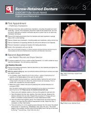
The osteotomy should be prepared with the aid of a<br />
surgical or prosthetic guide. The prosthetic component of<br />
the Inclusive ® Tooth Replacement Solution is a traditional<br />
surgical stent designed to convey the ideal position of the<br />
implant platform from the restorative perspective (Figs. 5, 6).<br />
By starting the osteotomy using this guide, the implant will<br />
be inserted in the appropriate location to take advantage of<br />
the custom temporary abutment and BioTemps ® provisional<br />
crown. The prosthetic guide is intended for prosthetic<br />
reference only, and does not take into consideration any<br />
anatomical landmarks or contraindications. This guide<br />
should be used in combination with the radiographic and<br />
clinical information to determine the best position for<br />
the implant.<br />
Figure 3: View of mandibular arch with proposed implant trajectory<br />
A surgical guide based on the virtual plan utilizing a CBCT<br />
scan of the patient provides the option of drill depth and<br />
angulation control. Based on the amount of guidance<br />
desired, a surgical guide can be produced that guides the<br />
pilot drill. Subsequent drilling with progressively wider<br />
20<br />
– www.inclusivemagazine.com –
Figure 4: Cross-sectional view of proposed implant site<br />
Figure 7: Universal SurgiGuide<br />
Figure 5: The Inclusive Tooth Replacement Solution prosthetic guide<br />
Figure 8: Universal SurgiGuide in situ<br />
surgical drills (as needed) and implant placement are<br />
performed freehand.<br />
If additional guidance is needed, Universal SurgiGuides (Materialise<br />
<strong>Dental</strong>; Glen Burnie, Md.) are available (Figs. 7, 8).<br />
In these cases, all the drills can be guided. The implant is<br />
placed freehand once the osteotomy has been created.<br />
At the time of placement, a custom healing abutment can be<br />
delivered (Figs. 9, 10). The custom healing abutment allows<br />
you to start anatomically sculpting the soft tissues at the<br />
time of surgery.<br />
Figure 6: Prosthetic guide in situ<br />
A custom temporary abutment and BioTemps crown also<br />
are provided with the Inclusive Tooth Replacement Solution.<br />
If high primary stability is achieved and the crown is<br />
taken well out of occlusion, the implant can be temporized<br />
at the time of surgery. Due to the occlusal forces that can be<br />
exerted in the molar region, another approach would be to<br />
utilize the custom healing abutment at the time of surgery<br />
and provisionalize the case at a later date.<br />
– Restoring Mandibular Single Teeth with the Inclusive Tooth Replacement Solution – 21
Temporization<br />
Temporization utilizing the Inclusive Tooth Replacement<br />
Solution consists of seating the custom temporary abut ment,<br />
then relining and cementing the BioTemps provisional crown<br />
(Fig. 11). If a screw-retained temporary is preferred, after<br />
adjustments are made, an occlusal hole is drilled through<br />
the crown (Fig. 12). The abutment and internal surfaces are<br />
roughened up to help create mechanical retention. A guide<br />
pin is used to maintain the screw opening, and the crown is<br />
luted to the abutment with permanent cement. The crownabutment<br />
assembly is then delivered to the implant (Fig. 13),<br />
and the abutment screw is tightened to 15 Ncm (Fig. 14).<br />
The occlusal screw is covered with a piece of Teflon tape<br />
and the access opening sealed with composite (Fig. 15). The<br />
crown should be out of occlusion (Fig. 16).<br />
Figure 9: Inclusive Tooth Replacement Solution custom healing abutment<br />
Final Impressions<br />
The final impression is made with the Inclusive Tooth<br />
Replacement Solution custom impression coping (Fig. 17).<br />
The custom impression coping allows you to transfer the<br />
position of the implant as well as the soft tissue contours to<br />
the master cast. The custom impression coping is seated on<br />
the implant and the screw is tightened (Fig. 18).<br />
The access opening is sealed with soft wax to prevent<br />
impression material from flowing into the coping (Fig. 19).<br />
The closed-tray impression is made following standard<br />
technique. When the material has set, the impression is<br />
pulled. The impression coping is removed and replaced<br />
with the healing abutment or provisional restoration. The<br />
shade is selected (Fig. 20) and clinical photos are taken.<br />
A bite registration and impression of the opposing arch<br />
are made. The pre-populated Inclusive Tooth Replacement<br />
Solution lab prescription is filled out and the case sent to<br />
the lab.<br />
Figure 10: Custom healing abutment in place with access opening sealed<br />
Laboratory Fabrication<br />
Upon receipt, the lab will mount the custom impression<br />
coping on an implant analog (Fig. 21) and reseat it back<br />
into the impression (Fig. 22). A soft tissue model will be<br />
poured (Fig. 23), the case articulated, and the final restoration<br />
fabricated.<br />
Figure 11: Custom temporary abutment and BioTemps crown<br />
Based on the clinician’s preference, a cemented or screwretained<br />
prosthesis can be ordered. In this case, the<br />
cemented restoration consisted of an Inclusive ® All-Zirconia<br />
Custom Abutment (Figs. 24a, 24b) and an IPS e.max ® crown<br />
(Ivoclar Vivadent; Amherst, N.Y.) (Fig. 25). An acrylic jig is<br />
fabricated to aid in seating the abutment (Figs. 26a, 26b).<br />
Final Delivery: Cement-Retained Crown<br />
When the healing abutment or provisional restoration<br />
is removed, the soft tissues will have healed to more<br />
Figure 12: After adjustments, a hole is drilled through the crown and the<br />
crown cemented to the abutment.<br />
22<br />
– www.inclusivemagazine.com –
Figure 13: Seated provisional restoration<br />
Figure 17: Custom impression coping<br />
Figure 14: The abutment screw is tightened<br />
Figure 18: The impression coping is seated<br />
Figure 15: The occlusal access opening is sealed<br />
Figure 19: The screw access opening is sealed with soft wax<br />
Figure 16: The temporary crown is out of occlusion<br />
Figure 20: Shade selection<br />
– Restoring Mandibular Single Teeth with the Inclusive Tooth Replacement Solution – 23
anatomically correct contours (Fig. 27). The abutment is<br />
seated utilizing the jig (Fig. 28) and the screw tightened<br />
to 35 Ncm (Fig. 29). The jig is then removed (Fig. 30). The<br />
crown is seated and the margins and interproximal and<br />
occlusal contacts are checked (Figs. 31a, 31b). Any necessary<br />
adjustments are made. There should be light centric contact<br />
with a firm bite and no lateral contacts. The interproximal<br />
contacts should be light. The abutment screw is tightened<br />
once more to 35 Ncm, and the access opening sealed with<br />
a piece of Teflon tape. The crown is cemented in place<br />
with RelyX Unicem Self-Adhesive Resin Cement (3M ESPE;<br />
St. Paul, Minn.). All excess cement must be meticulously<br />
removed. A PA was taken to verify complete seating and<br />
cement removal (Fig. 32).<br />
Final Delivery:<br />
IPS e.max Screw-Retained Crown<br />
If a screw-retained crown was selected (Figs. 33a–33c), the<br />
one-piece restoration is seated on the implant (Fig. 34). The<br />
abutment screw is tightened to 35 Ncm utilizing the jig<br />
(Fig. 35). The interproximal and occlusal contacts are<br />
checked and adjusted as needed (Fig. 36). The screw access<br />
opening is sealed with a piece of Teflon tape and an occlusal<br />
composite (Fig. 37).<br />
Figure 22: Assembly reseated into impression<br />
Summary<br />
Replacement of missing mandibular molars with singletooth<br />
implant-borne restorations provides many benefits<br />
over fixed partial dentures. It avoids having to prep adjacent<br />
teeth, it makes hygiene easier for the patient, and it allows<br />
for flexure of the mandible. 2 The osteotomy can be created<br />
conventionally or through a guided surgical procedure.<br />
The Inclusive Tooth Replacement Solution provides the<br />
components to simplify the restorative process and provide<br />
a superior final restoration for this common restoration. IM<br />
Figure 23: Soft tissue model<br />
Figures 24a, 24b: Inclusive All-Zirconia Custom Abutment<br />
Figure 21: Custom impression coping mounted on implant analog<br />
Figure 25: Inclusive All-Zirconia Custom Abutment and IPS e.max crown<br />
24<br />
– www.inclusivemagazine.com –
Figures 26a, 26b: Acrylic abutment seating jig<br />
Figure 30: The jig is removed<br />
Figure 27: The provisional restoration is removed<br />
Figures 31a, 31b: After adjustments, the IPS e.max crown is cemented in place<br />
Figure 28: The abutment is seated with the jig<br />
Figure 32: PA verifying seating and cement removal<br />
Figure 29: The abutment screw is tightened to 35 Ncm<br />
Figures 33a–33c: IPS e.max screw-retained crown<br />
– Restoring Mandibular Single Teeth with the Inclusive Tooth Replacement Solution – 25
References<br />
1. Becker W, Becker BE. Replacement of maxillary and mandibular molars with single<br />
endosseous implant restorations: a retrospective study. J Prosthet Dent. 1995 Jul;<br />
74(1):51–55.<br />
2. Misch CE, Misch-Dietsh F, Silc J, Barboza E, Cianciola LJ, Kazor C. Posterior<br />
implant single-tooth replacement and status of adjacent teeth during a 10-year<br />
period: a retrospective report. J Periodontol. 2008 Dec;79(12):2378-82.<br />
3.Misch CE. Endosteal implants for posterior single tooth replacement: alternatives,<br />
indications, contraindications, and limitations. J Oral Implantol. 1999;25(2):80-94.<br />
4. Ekfeldt A, Carlsson GE, Börjesson G. Clinical evaluation of single tooth restorations<br />
supported by osseointegrated implants: a retrospective study. Int J Oral<br />
Maxillofac Implants. 1994 Mar-Apr;9(2):179–83.<br />
5. Muftu A, Chapman RJ. Replacing posterior teeth with freestanding implants: fouryear<br />
prosthodontic results of a prospective study. J Am Dent Assoc. 1998 Aug;<br />
129(8):1097–102.<br />
6. Jansen C. Presentation given at the Academy of Osseointegration 2012 Annual<br />
Meeting, Phoenix, Ariz.<br />
7. Anderson LC, Kosinski TF, Mentag PJ. A review of the intraosseous course of the<br />
nerves of the mandible. J Oral Implantol. 1991;17(4):394-403.<br />
8. Alhassani AA, AlGhamdi AS. Inferior alveolar nerve injury in implant dentistry: diagnosis,<br />
causes, prevention, and management. J Oral Implantol. 2010;36(5):401-7.<br />
Epub 2010 Jun 14.<br />
Figure 34: Abutment screw tightened utilizing jig<br />
Figure 35: IPS e.max screw-retained crown seated<br />
Figure 36: Occlusion verified<br />
Figure 37: Access opening sealed with composite<br />
26<br />
– www.inclusivemagazine.com –
IMPLANT POSITION<br />
IN THE ESTHETIC ZONE<br />
Go online for<br />
in-depth content<br />
by<br />
Siamak Abai, DDS, MMedSc<br />
Since the advent of modern root<br />
form osseointegrated implant<br />
dentistry in 1952 by Per-Ingvar<br />
Brånemark 1 and colleagues, clinicians<br />
have strived for improvements in<br />
implant positioning in the esthetic<br />
zone to achieve predictable restorative<br />
and esthetic results. Years of clinical<br />
experience in congruence with controlled<br />
clinical studies have led to<br />
established parameters as a guide<br />
for these results. Prosthetic treatment<br />
planning and establishing a set clinical<br />
protocol prior to implant placement<br />
are paramount. It is important to note<br />
that proper implant positioning is<br />
patient- and often implant-specific, and<br />
that inter-patient generalizations can<br />
result in myopic treatment planning<br />
and decrease the predictability of an<br />
esthetic outcome.<br />
Treatment planning prior to implant placement traditionally<br />
begins with comprehensive medical and dental evaluation,<br />
articulated diagnostic casts, periapical and panoramic radiographs,<br />
cone beam computed tomography (CBCT) scans, and<br />
a diagnostic wax-up. Patient demands must always be taken<br />
into consideration prior to surgery, and presurgical mockups<br />
may be necessary to convey the information to the patient.<br />
Prosthetic treatment planning helps the clinician with a<br />
restorative-driven implant placement rather than a bonedriven<br />
approach, with the latter leading to poor abutment<br />
angulations and drastically reduced restorative options. Bone<br />
augmentation is often necessary in order to achieve optimal<br />
residual ridge dimensions prior to implant placement.<br />
The inventive work of Sir Godfrey Hounsfield 2 and the<br />
advancement of CBCT technology have led the dental<br />
profession into a new realm of dimensional accuracy that<br />
is often unattainable with conventional dental radiography.<br />
In combination with the use of a surgical or guided stent,<br />
proper 3-D positioning of a dental implant has become<br />
an attainable goal, leading to increased confidence for<br />
the clinician and accurate clinical results. The importance<br />
– Implant Position in the Esthetic Zone – 27
IMPLANT POSITION IN THE ESTHETIC ZONE<br />
of the implant position can be manifested in the four<br />
dimensionally sensitive positioning criteria: mesiodistal,<br />
labiolingual, and apico-coronal location, as well as implant<br />
angulation. 3 The ultimate goal is not only to avoid adjacent<br />
sensitive structures, but to respect the biological principles<br />
that have been established to achieve esthetic results.<br />
MESIODISTAL CRITERIA<br />
Correct implant position in a mesiodistal orientation allows<br />
the clinician to avoid iatrogenic damage to adjacent critical<br />
structures. Maintaining adequate distance from adjacent<br />
teeth also helps preserve crestal bone and interproximal<br />
papillary height. When placing an implant adjacent to a<br />
tooth, it has been shown that crestal bone peak is based on<br />
and maintained by the bone level of the teeth adjacent to<br />
the missing space. A minimum distance of 1.5 mm between<br />
implant and existing dentition has been determined to<br />
prevent damage to the adjacent teeth and to provide proper<br />
osseointegration and gingival contours 4–6 (Fig. 1a). Implants<br />
placed too closely together can reduce the height of the<br />
inter-implant bone crest, and a distance of less than 3 mm<br />
between two adjacent implants leads to increased bone<br />
loss. It has been shown that a distance of more than 3 mm<br />
between two adjacent implants preserves the interproximal<br />
bone peak and results in 0.45 mm of resorption on average,<br />
giving a better chance of proper interproximal papillary<br />
height (Fig. 1b). If the space between implants is 3 mm<br />
or less, the average resorption of the interproximal bone<br />
peak increases to 1.04 mm, compromising support for the<br />
interdental papilla. 4,7 As a result, wide-bodied implants less<br />
than 3 mm apart in the esthetic zone would compromise<br />
the desired outcome.<br />
LABIOLINGUAL CRITERIA<br />
Labiolingual implant position is often determined by the<br />
gingival biotype, occlusal considerations of opposing teeth,<br />
and desired emergence profile. An implant placed too far<br />
labially can cause bone dehiscence and gingival recession<br />
leading to exposure or show-through of the implant collar.<br />
An implant placed too far lingually can cause prosthetic<br />
difficulties with ridge-lap restorations that can be unhygienic<br />
and unesthetic. A thickness of 1.8 mm of labial bone has<br />
been determined to be critical in maintaining an implant soft<br />
tissue profile and increasing the likelihood of an esthetic<br />
outcome 8 (Fig. 2). Labially oriented implants compromise<br />
the subgingival emergence profile development, creating<br />
long crowns and misalignment of the collar with respect to<br />
the adjacent teeth. 9<br />
APICO-CORONAL CRITERIA<br />
Peri-implant crestal bone stability plays a critical role in the<br />
presence of interdental papilla. 10 Many factors contribute<br />
to crestal bone resorption, including existing anatomy, surgical<br />
trauma, overloading, peri-implantitis, implant surface<br />
characteristics, microgap at the implant-abutment junction,<br />
Figure 1a: Minimum distance of 1.5 mm between implant and existing dentition<br />
Figure 1b: Minimum distance of 3 mm between two adjacent implants<br />
Figure 2: Proper labiolingual placement with 1.8 mm thickness of labial bone<br />
28<br />
– www.inclusivemagazine.com –
type of connection between implant, and prosthetic components.<br />
11 Several factors are cause for concern in the<br />
apico-coronal placement of implants. Implants placed too<br />
shallow may reveal the metal collar of the implant through<br />
the gingiva. Countersinking implants below the level of<br />
the crestal bone may give prosthetic advantages with more<br />
running room for prosthetic components and tissue contouring,<br />
but can lead to crestal bone loss due to the location<br />
of a microgap at the implant-abutment interface. The<br />
ideal solution to exposure of the implant collar would be<br />
the placement of an implant equicrestal or subcrestal to<br />
the ridge. However, the existing microgap at the implantabutment<br />
junction leads to bone resorption due to periimplant<br />
inflammation. 12 It is suggested that an implant collar<br />
be located 2 mm apical to the CEJ of an adjacent tooth<br />
if no gingival recession is present 13 (Fig. 3). Implant diameter<br />
also plays a role in apico-coronal position, with smaller<br />
diameter implants needing more space for soft-tissue development<br />
and tissue contouring.<br />
Figure 4: Proper implant angulation with screw access in the cingulum area<br />
Figure 3: Lateral view of implant placed with the collar at the level of crestal bone<br />
with adjacent teeth CEJ 2 mm coronal to the collar of the implant<br />
IMPLANT ANGULATION<br />
Implant angulation is particularly important in treatment<br />
planning for screw-retained restorations. Implants angled<br />
too far labially compromise the placement of the restorative<br />
screw, leaving the clinician with fewer restorative options.<br />
Implants angled too far lingually can result in unhygienic<br />
and unesthetic prosthetic design. For every millimeter<br />
of lingual inclination, the implant should be placed an<br />
additional millimeter apically in order to create an optimal<br />
emergence profile. 14 In general, implant angulation should<br />
mimic angulation of adjacent teeth so long as they are<br />
in reasonable alignment (Fig. 4). Furthermore, maxillary<br />
anterior regions require a subtle palatal angulation to<br />
INCLUSIVE TOOTH<br />
REPLACEMENT SOLUTION<br />
The Inclusive ® Tooth Replacement Solution was developed<br />
by <strong>Glidewell</strong> Laboratories as a complete, prosthetically<br />
driven method of restoring missing dentition. The solution<br />
comprises treatment planning, implant placement, patientspecific<br />
temporization, and the definitive restoration<br />
(Figs. 5a–5f). When utilizing the comprehensive range of<br />
Inclusive Digital Treatment Planning services for guided<br />
implant surgeries and restorations, the clinician has absolute<br />
and precise control of each step. This results in an efficient<br />
and accurate workflow that is beneficial for the clinician and,<br />
ultimately, the patient. With the Inclusive Tooth Replacement<br />
Solution, the clinician has control of the four dimensions of<br />
implant placement in the esthetic zone, creating a consistently<br />
predictable result. Having a single source of services and<br />
materials is also advantageous in providing a more affordable<br />
yet high-value product for patients.<br />
increase labial soft tissue bulk. 15 – Implant Position in the Esthetic Zone – 29
IMPLANT POSITION IN THE ESTHETIC ZONE<br />
Figure 5a: Inclusive Tapered Implant at placement<br />
Figure 5b: Inclusive custom healing abutment in place<br />
Figure 5c: Contoured soft tissue sulcus after healing<br />
Figure 5d: Screw-retained IPS e.max ® crown (Ivoclar<br />
Vivadent; Amherst, N.Y.) in place<br />
Figure 5e: PA to verify seating of crown<br />
Figure 5f: Buccal view of final restoration at delivery<br />
IM<br />
REFERENCES<br />
1. Albrektsson T, Brånemark PI, Hansson HA, Lindstrom J. Osseointegrated titanium<br />
implants. Requirements for ensuring a long-lasting, direct bone-to-bone<br />
implant anchorage in man. Acta Orthop Scand. 1981;52(2):155-70.<br />
2. Hounsfield GN. Computerized transverse axial scanning (tomography): Part I.<br />
Description of system. Br J Radiol .1973;46:1016-22.<br />
3. Al-Sabbagh M. Implants in the esthetic zone. Dent Clin N Am. 2006 Jul;50(3):<br />
391-407.<br />
4. Tarnow DP, Cho SC, Wallace SS. The effect of inter-implant distance on the<br />
height of inter-implant bone crest. J Periodontol. 2000 Apr;71(4):546-49.<br />
5. Spray JR, Black CG, Morris HF, Ochi S. The influence of bone thickness on<br />
facial marginal bone response: stage 1 placement through stage 2 uncovering.<br />
Ann Periodontol. 2000 Dec;5(1):119–28.<br />
6. Saadoun AP, LeGall M, Touati B. Selection and ideal tridimensional implant position<br />
for soft tissue aesthetics. Pract Periodontics Aesthet Dent. 1999 Nov-Dec;<br />
11(9):1063-72.<br />
7. Degidi M, Perrotti V, Shibli JA, Novaes AB, Piatelli A, Lezzi G. Equicrestal and<br />
subcrestal dental implants: a histologic and histomorphometric evaluation of<br />
nine retrieved human implants. J Periodontol. 2011 May;82(5):708-15. Epub<br />
2010 Dec 7.<br />
8. Hermann JS, Buser D, Schenk RK, Schoolfield JD, Cochran DL. Biological width<br />
around one- and two-piece titanium implants. Clin Oral Implants Res. 2001 Dec;<br />
12(6):559-71.<br />
9. Kazor CE, Al-Shammari K, Sarment DP, Misch CE, Wang HL. Implant plastic<br />
surgery: a review and rationale. J Oral Implantol. 2004;30(4):240-54.<br />
10. Berglundh T, Lindhe J. Dimension of the periimplant mucosa. Biological width<br />
revisited. J Clin Periodontol. 1996 Oct;23(10):971-73.<br />
11. Hermann F, Lerner H, Palti A. Factors influencing the preservation of the<br />
periimplant marginal bone. Implant Dent. 2007 Jun;16(2):165-75.<br />
12. Broggini N, McManus LM, Hermann JS, Medina RK, Buser D, Cochran DL.<br />
Peri-implant inflammation defined by the implant-abutment interface. J Dent<br />
Res. 2006 May;85(5):473-78.<br />
13. Saadoun AP, LeGall M, Touati B. Selection and ideal tridimensional implant<br />
position for soft tissue aesthetics. Pract Periodontics Aesthet Dent. 1999<br />
Nov-Dec;11(9):1063-72.<br />
14. Potashnick SR. Soft tissue modeling for the esthetic single-tooth implant restoration.<br />
J Esthet Dent. 1998;10(3):121-31.<br />
15. Tishler M. <strong>Dental</strong> implants in the esthetic zone. Considerations for form and<br />
function. N Y State Dent J. 2004 Mar;70(3):22-6.<br />
30<br />
– www.inclusivemagazine.com –
SMALL DIAMETER<br />
implants<br />
Planning from the<br />
Prosthetic Perspective<br />
with Bradley C. Bockhorst, DMD<br />
Whether you’re placing small-diameter or conventionaldiameter<br />
implants for an overdenture, the case must be<br />
planned from surgical and prosthetic perspectives. The<br />
restorative aspect of the Inclusive ® Mini Implant involves<br />
encasing the O-ring housings within the denture base and<br />
creating a parallel line of draw.<br />
O-ring Housing Dimensions<br />
4.75 mm<br />
The height of the O-ring housing is 3.5 mm (Fig. 1). There<br />
is a space of approximately 1.0 mm between the top of<br />
the collar and the base of the O-ring housing to allow<br />
the housing to be rotated in cases where the implants<br />
are divergent. The housings can accommodate up to<br />
30 degrees of angular divergence between implants.<br />
However, the implants should be placed parallel to one<br />
another as much as possible to provide an ideal prosthetic<br />
fit and to avoid excessive wearing of the O-rings.<br />
There should be a minimum of 3 mm thickness of acrylic<br />
in the denture base above the housing to provide adequate<br />
strength to the prosthesis. Therefore, there should be at<br />
least 8 mm of vertical space from the top of the collar. The<br />
denture teeth would be in addition to this space.<br />
1.0 mm<br />
Figure 1: O-ring housing with 3.5 mm height<br />
3.5 mm<br />
– Small Diameter Implants: Planning from the Prosthetic Perspective – 31
Figure 2a: Cast framework<br />
Figure 2b: Framework incorporated into overdenture<br />
Providing implant-retained<br />
overdentures can be one of the<br />
most professionally rewarding<br />
aspects of your practice.<br />
Figure 3: Virtual framework design with strut over attachment housing<br />
If vertical space is lacking, a cast framework can be incorporated<br />
into the new denture to provide strength (Figs. 2a, 2b).<br />
Frameworks are designed to have a strut over the top of the<br />
attachment housing (Fig. 3).<br />
In mandibular overdenture cases, it is customary to place<br />
four mini implants within the symphysis area with as wide<br />
an anterior-posterior spread as possible while still ensuring<br />
an adequate margin of safety from the nerve (Fig. 4a).<br />
In maxillary overdenture cases, it is customary to place six<br />
mini implants anterior to the sinuses (Fig. 4b). The O-ring<br />
housings are 4.75 mm in diameter, and there should be at<br />
least 2 mm of acrylic between these metal housings in the<br />
denture base (Fig. 5). Therefore, the centers of the implants<br />
should be at least 7 mm apart.<br />
Providing implant-retained overdentures can be one of<br />
the most professionally rewarding aspects of your practice<br />
— and it can be life-changing for your patients. Planning<br />
from both the prosthetic perspective and the surgical<br />
perspective will help the cases go smoothly and minimize<br />
future complications. IM<br />
32<br />
– www.inclusivemagazine.com –
Mandibular Spacing<br />
Maxillary Spacing<br />
Figure 4a: Typical placement of mini implants in the mandible<br />
Figure 4b: Typical placement of mini implants in the maxilla<br />
Figure 5: Digital treatment plan for four Inclusive Mini Implants in an edentulous mandible. Cross-sectional view (upper right quadrant) shows O-ring housing well positioned<br />
within the denture base.<br />
– Small Diameter Implants: Planning from the Prosthetic Perspective – 33
CLINICAL<br />
TIP<br />
Bone Quality Based Drilling Protocol:<br />
Achieving High Primary Stability<br />
by<br />
Darrin M. Wiederhold, DMD, MS<br />
Figure 1:<br />
Planning software<br />
used to evaluate<br />
relative bone<br />
density showing<br />
Type IV bone<br />
ONE OF THE MOST FUNDAMENTAL PROCEDURES performed<br />
by implant surgeons is the creation of the osteotomy for<br />
implant placement. Without a well-developed osteotomy<br />
site, both the immediate surgical and future restorative<br />
success of the case can be compromised. There are various<br />
factors that must be considered when performing the<br />
osteotomy, such as location, angulation, and spacing for<br />
multiple implants. Critical decisions to be made concern the<br />
choice of whether to follow the soft or dense bone protocol<br />
for a given case, and whether to utilize a bone tap drill. The<br />
goal is to achieve high primary stability, at least 35 Ncm,<br />
at the time of implant placement. This will also impact the<br />
decision whether to immediately provisionalize the case.<br />
As with most things implant-related, assessment of the<br />
preoperative bone quality and quantity is critical to planning<br />
the osteotomy. If using conventional radiography, such as<br />
periapicals and panoramics, evaluation of the trabecular<br />
pattern of the bone, the amount of cortical versus cancellous<br />
bone, and the vertical height of the bone can often indicate<br />
the likely density of the underlying bone. The use of cone<br />
beam computed tomography (CBCT) and digital treatment<br />
planning software can provide an even clearer preoperative<br />
assessment of the bone to be drilled, by allowing the surgeon<br />
to examine the bone three dimensionally, and providing a<br />
Hounsfield or relative density scale of a planned osteotomy<br />
site (Fig. 1). By carefully considering all of these factors, the<br />
surgeon often has a sense of which drilling protocol will be<br />
– Clinical Tip: Bone Quality Based Drilling Protocol – 35
used before the patient even presents for the surgery. As is<br />
often the case, however, many surgical decisions are made<br />
intraoperatively. In essence, sometimes even the best-laid<br />
plans need modification.<br />
A good rule of thumb in osteotomy preparation is to start<br />
small and advance as needed. In other words, drill to the<br />
manufacturer’s recommendations for your specific implant<br />
system for soft bone. Once you have done so, if you feel<br />
that the bone was particularly difficult to penetrate with the<br />
drills, or, when you attempt to place the implant, it does not<br />
easily advance to full depth, then it is typically advisable<br />
to enlarge the osteotomy diameter with the dense bone<br />
drill. The potential dangers in not having an adequately<br />
sized osteotomy include: damaging the implant connection<br />
during placement, not fully seating and properly positioning<br />
the implant in the bone, and creating excess pressure on the<br />
surrounding bone. All of these are detrimental to the longterm<br />
success of the implant and restoration. Some surgeons<br />
advocate drilling to the dense bone diameter in all cases.<br />
This is certainly an option, but the risk is that you could<br />
compromise the amount of initial stability that you achieve<br />
and that the drill or the implant could be displaced into an<br />
unfavorable location due to loss of resistance and torque.<br />
So, again, it is at the discretion of the surgeon.<br />
Screw taps are used in cases of extremely dense bone,<br />
Type I and perhaps Type II. Essentially, the screw taps<br />
precisely mimic the thread patterns of the proposed implant.<br />
Therefore, by tapping the bone with these specialized drills,<br />
the internal configuration of the osteotomy is identical to<br />
that of the threads of the planned implant. This allows for<br />
a more passive, complete placement of the implant with<br />
less insertional torque, and is therefore gentler to the<br />
surrounding bone. Many implants today purport to be<br />
self-threading or tapping, often eliminating the need for<br />
the screw tap. But in those instances where the bone is<br />
particularly dense, screw taps are useful. The screw tap<br />
may be used as an alternative to, or in conjunction with, the<br />
dense bone drill.<br />
There is a great deal of latitude in the choice of whether to<br />
utilize the soft or dense bone protocol, as well as whether<br />
to use a screw tap (Fig. 2). From pre- and intraoperative<br />
evaluation of the bone quality and density, to the decision to<br />
precisely shape the internal anatomy of the osteotomy site<br />
with a screw tap, a variety of factors must be considered to<br />
create the ideal osteotomy and achieve good implant primary<br />
stability. But the extra time and attention to detail needed to<br />
make that informed decision will be rewarded with simpler<br />
surgeries and long-term restorative success. IM<br />
Figure 2: Drill sequence for 4.7 mm x 11.5 mm<br />
Inclusive Tapered Implant. The dense bone drill<br />
and screw tap are optional. Note: Drill charts for<br />
3.7 mm and 5.2 mm Inclusive Tapered Implants<br />
are also available.<br />
Short<br />
Drills<br />
Long<br />
Drills<br />
16 mm<br />
13 mm<br />
11.5 mm<br />
10 mm<br />
8 mm<br />
Ø1.5 mm<br />
Lance Drill<br />
Ø2.3/2.0 mm<br />
Pilot Drill<br />
Ø2.8/2.3 mm<br />
Surgical Drill<br />
Ø3.4/2.8 mm<br />
Surgical Drill<br />
Final Drill<br />
Soft Bone<br />
Ø3.8/3.4 mm<br />
Surgical Drill<br />
Final Drill<br />
Dense Bone<br />
Ø4.4/3.8 mm<br />
Surgical Drill<br />
Optional<br />
Dense Bone<br />
Ø4.7 mm<br />
Screw Tap<br />
Ø4.7 mm<br />
Inclusive<br />
Tapered Implant<br />
36<br />
– www.inclusivemagazine.com –
Implant&<br />
Q A:<br />
Go online for<br />
in-depth content<br />
An Interview with Dr. David Little<br />
Interview of David A. Little, DDS<br />
by Bradley C. Bockhorst, DMD<br />
Dr. David Little maintains a multidisciplinary, state-of-the-art<br />
dental practice in San Antonio, Texas, where he dedicates himself<br />
to developing and refining his knowledge skills — as well as those<br />
of his colleagues and peers — through extensive continuing<br />
education and product research. As a clinical researcher<br />
focusing on implants, restorative materials, and technology,<br />
Dr. Little develops predictable procedures for successful<br />
functional and esthetic outcomes. His passion for helping others<br />
drives him to share this expertise in emerging restorative<br />
techniques and materials, as evident in the following interview.<br />
Dr. Bradley Bockhorst: Your practice<br />
is a little different from the typical practice<br />
out there. Tell us how you’re set up.<br />
Dr. David Little: My practice is in a little<br />
town called China Grove, which the<br />
Doobie Brothers made famous. It’s a<br />
sleepy little town around San Antone,<br />
but you can see downtown from my<br />
office. I built the office around a lake,<br />
so all the treatment rooms look out on<br />
the water. One half of the office is a<br />
specialty wing. I have a fully equipped<br />
surgical suite and orthodontic bay,<br />
and every specialist in dentistry rotates<br />
through my practice. We have<br />
CBCT technology, intraoral scanners,<br />
lab support — just about everything<br />
under one roof. And they’re not part<br />
of my practice, they just rent from me.<br />
Together we provide many services.<br />
BB: So you can refer a case and still<br />
keep it in-house?<br />
DL: Exactly.<br />
BB: You’re a general dentist. You place<br />
and restore implants. How do you decide<br />
which ones you’re going to place<br />
and those you’re going to refer out?<br />
– Implant Q&A: An Interview with Dr. David Little – 39
BB: Sounds like it’s a truly interdisciplinary<br />
practice.<br />
DL: Absolutely. We’re really blessed to<br />
be able to jump in and take care of<br />
things, especially trauma cases.<br />
BB: You mentioned medical considerations<br />
as a determining factor when deciding<br />
what you might refer out. What<br />
are red flags for you when you’re looking<br />
at a patient’s medical history?<br />
Figure 1: Digital treatment plan<br />
Figure 2: Surgical guide<br />
Figure 3: Denture-modified surgical stent<br />
The key to<br />
success is<br />
treatment<br />
planning from<br />
the restoration<br />
backward.<br />
DL: First of all, you look at medical<br />
history. Also, in our office, we can do<br />
everything from just local anesthesia<br />
all the way to IV sedation, depending<br />
on what patients want along those<br />
lines. Then, the key is to determine<br />
the factors necessary for success: Is<br />
it great bone? Is it good occlusion? Is<br />
everything set up to make it successful?<br />
If so, then it’s one that I’m going to do.<br />
If the patient needs a sinus lift or bone<br />
augmentation, I’m going to refer it. We<br />
do really well referring together. The<br />
oral surgeon will do the bone grafts,<br />
we’ll do the implants, or if we need<br />
periodontal plastic surgery, we’ll bring<br />
in the periodontist. It actually works<br />
very well.<br />
DL: Uncontrolled diabetes, blood disorders,<br />
the use of bisphosphonates —<br />
those are things that we shy away<br />
from. Essentially anything that makes<br />
us uncomfortable. If I wouldn’t do an<br />
extraction, then I’m probably not going<br />
to do an implant on them. So, I use<br />
that as my guideline.<br />
BB: Do you have any advice for aspiring<br />
implantologists — how they should<br />
get started, and what they should look<br />
for in first cases?<br />
DL: First of all, I think you need to<br />
have an eye for implants. I think you<br />
have to start looking for cases where<br />
implants will be the best solution for<br />
the patient. Second, get educated.<br />
Go out and really learn your craft.<br />
And then use mentors. Mentors are a<br />
really good thing. Today, by using a<br />
team approach, you can work with a<br />
laboratory like <strong>Glidewell</strong>, and sit down<br />
and plan out the case, looking at it<br />
from the restorative aspect backward,<br />
so that everything is planned out. By<br />
using CBCT and surgical guides, you<br />
can do it very predictably and get<br />
great results. The bottom line is: It’s<br />
better for our patients.<br />
BB: You mentioned earlier that you have<br />
a cone beam scanner in your office.<br />
DL: I do. Even before I had one, I<br />
would send it out to get that done<br />
because I think it’s really valuable information.<br />
Sometimes all you need is<br />
a scan to say, “Yes, OK, I’ve got this<br />
much bone — great.” Sometimes I<br />
look at it and go: “Wow, I’m glad I did<br />
that. I didn’t want to do that case.”<br />
40<br />
– www.inclusivemagazine.com –
But the real key is not just the CBCT.<br />
It’s putting it in the software and being<br />
able to manipulate it. I call it virtual<br />
planning. I want to be able to show<br />
my patient that I’m going to put in<br />
this size implant, and this is why, and<br />
this is how it’s going to be contoured<br />
and shaped, all the way to the final<br />
restoration. Because I think the key to<br />
success is treatment planning from the<br />
restoration backward.<br />
BB: What is your favorite planning software?<br />
There are several on the market.<br />
DL: I use SimPlant ® (Materialise <strong>Dental</strong><br />
Inc.; Glen Burnie, Md.), mostly<br />
because you can use every implant<br />
system. But with whatever implant<br />
you’re using, there is going to be a<br />
system that will work with you. So,<br />
again, I think you’ve got to look at the<br />
total picture.<br />
BB: We’ve had the same experience. We<br />
do a lot of SimPlant cases here because it<br />
has an open architecture. Let’s talk about<br />
guided surgery and level of guidance.<br />
DL: Obviously, you can have the lab<br />
make a guide for you from a wax-up.<br />
That will kind of give you the position,<br />
but it doesn’t really give you the angle,<br />
doesn’t give you the depth. It just gives<br />
you a guide to stay within that area.<br />
Or you can go all the way to where<br />
you can actually control depth, angle,<br />
and position; you can even place the<br />
implant through the guide (Figs. 1, 2).<br />
Everything is planned out. I like that<br />
the best because it gives me the perfect<br />
emergence profile. The software helps<br />
me establish what my abutment is<br />
going to be like, so the laboratory can<br />
work with me to create a provisional<br />
that stays in that same position —<br />
everything is worked through.<br />
I’ll also say that using even the<br />
patient’s denture as a guide is huge<br />
because that makes sure that you keep<br />
those implants in the neutral zone,<br />
and you’re going to get a great result<br />
as well (Fig. 3). There are a lot of guide<br />
techniques, but I like using the one<br />
that controls all of it, if I can.<br />
BB: At the California <strong>Dental</strong> Association<br />
(CDA) meeting in Anaheim last<br />
May, you spoke on the topic of overdentures.<br />
Can you talk a little bit about how<br />
you approach your edentulous patients?<br />
DL: A lot of denture patients are dental<br />
cripples. They really can’t function<br />
and they can’t eat. So, one of the<br />
things I do is I ask them, “Do you want<br />
to eat what you want, or eat only what<br />
you can?” Then I talk about what the<br />
different solutions are. I ask questions<br />
like, “At the end of this, would you just<br />
like it that your denture stays in a little<br />
better, or are you looking for something<br />
that you never have to take out?”<br />
Their answers will tell you the direction<br />
they want to go. Then I look at<br />
implant-retained, soft tissue-supported<br />
as a solution. You can do that with<br />
mini implants, or you can do that with<br />
two or four conventional implants,<br />
with different attachments such as O-<br />
rings and Locator ® attachments (Zest<br />
Anchors; Escondido, Calif.) (Figs. 4, 5).<br />
Or, you could go to implant-retained,<br />
implant-supported. The ANKYLOS ®<br />
SynCone ® (DENTSPLY Friadent) is what<br />
I use for that particular one. It is implant-retained<br />
and implant-supported,<br />
but still removable. And, finally, we<br />
have the option to go screw it in and<br />
either use processed denture teeth,<br />
which are very esthetic today, or make<br />
it out of porcelain.<br />
So, you have that whole range of solutions.<br />
And I really like what <strong>Glidewell</strong><br />
has done in establishing one fee. If you<br />
ask a dentist how much an implant<br />
costs, they know the surgical fee off the<br />
top of their head. But if you ask them<br />
how much a crown is, they go: “Uh, it<br />
depends.” On what? Well, it depends<br />
on abutments, etc. So it’s having a<br />
solution — a two-implant solution, a<br />
four-implant solution. If you include<br />
everything in that, it’s just a whole lot<br />
better when you present it to patients.<br />
BB: And you understand all your costs<br />
as a dentist. Talking about the edentulous<br />
patient, how do you make that<br />
decision between a screw-retained denture<br />
and a crown & bridge procedure?<br />
Figure 4: Locator attachments and overdenture<br />
Figure 5: Restored overdenture case<br />
DL: I look at the situation and treat<br />
it four ways: First, I look at it and<br />
treat it in my mind. Second, I wax it<br />
up so I can see if what I’m thinking<br />
can work. Then I sit down with the<br />
lab and we discuss how this is going<br />
to work out. Then we ask the patient<br />
because they’re most important. That’s<br />
who we’re doing it for. Do they want it<br />
fixed? Hopefully, if they want it fixed,<br />
they have enough bone to do it. That’s<br />
usually what we have to deal with. If<br />
they do have enough bone, then I tell<br />
them, “Look, if you have a lower denture,<br />
you’re eating at about 10 percent<br />
efficiency.” If I put in two or four implants<br />
— implant-retained, soft-tissue<br />
supported — you’ll be at about 40 to<br />
60 percent. But if you really want to<br />
– Implant Q&A: An Interview with Dr. David Little – 41
Figure 6: Double-cord tissue retraction and laser<br />
troughing tissue management<br />
get back to the way you were chewing,<br />
we can do this screw-retained, or<br />
porcelain, and then I can get you back<br />
to functioning even better than you<br />
were before. So, those are the things<br />
I look at. And I really ask that question<br />
of my patients: “Do you want to<br />
eat what you want, or eat only what<br />
you can?”<br />
BB: Regarding screw-retained dentures<br />
versus porcelain, how do you make a<br />
decision on which way to go?<br />
DL: That’s a good question. What do<br />
patients think? They all think porcelain<br />
is better. Well, porcelain is better<br />
if you have the space for it. And<br />
lip support is the number one thing.<br />
You’ve got to do a wax rim and make<br />
sure your lip support is proper because<br />
I think you can do a better job<br />
with acrylic a lot of times. So, it’s all<br />
in the diagnosis — looking at it and<br />
seeing what is best for that individual<br />
patient. Because the cost on those is<br />
not as much as you’d think, when you<br />
get to that point. A lot of factors are involved,<br />
but really, listen to the patient.<br />
I think that’s the main thing.<br />
BB: A suggestion I’ve heard you give in<br />
When I talk to<br />
young dentists<br />
who are coming<br />
out of dental<br />
school, I tell<br />
them, “Don’t<br />
biopsy wallets.”<br />
... Always do<br />
what’s best.<br />
a past presentation is, “Treat the patient<br />
as you’d treat yourself.” Can you expand<br />
on that treatment approach?<br />
DL: When I talk to young dentists<br />
who are coming out of dental school,<br />
I tell them, “Don’t biopsy wallets.”<br />
Treatment plan what you would do<br />
for yourself, for your mom. Don’t<br />
make value judgments. Tell them what<br />
you’d recommend. You can always<br />
back off and sequence it, but always<br />
do what’s best. They want what’s right.<br />
I think that’s my best advice: Don’t<br />
biopsy wallets.<br />
BB: I also know you’re a big proponent<br />
of education and the importance of<br />
educating the team. What are your<br />
thoughts along those lines?<br />
DL: Here’s the truth: As dentists, we<br />
spend more time with our team than<br />
we do with our family during waking<br />
hours, so we’ve got to be on the<br />
same page. So many times you go to<br />
a seminar and you’re all fired up, but<br />
when you come back to the office, after<br />
a couple weeks, things are back<br />
to normal. Unless you take it back<br />
and implement it, nothing happens.<br />
And the key to that is, when you do<br />
bring implants into your practice, you<br />
have to have systems, strategies, and<br />
everybody talking the same language<br />
because the very first part of case acceptance<br />
is the phone call. Sometimes<br />
I’ll actually do random care calls. I’ll<br />
call offices and say, “I need implants,”<br />
and see what they say because everybody<br />
needs to be on the same page.<br />
BB: We were talking about different<br />
technologies — guided surgery, cone<br />
beam scanning. Another is intraoral<br />
scanning. Are you involved in that?<br />
DL: Absolutely, and I’ve been involved<br />
with that from the beginning. Looking<br />
at the different technologies out there,<br />
I definitely get better fits when I use<br />
an intraoral scanning device. I definitely<br />
get less chairtime when I seat<br />
them, so that’s the real value for the<br />
dentist. There’s also that wow factor.<br />
Patients love it, there’s no gagging. But<br />
I really think it also makes you a better<br />
dentist. If we take an impression<br />
and look at it and go, “It looks pretty<br />
good, the lab will make that work”<br />
versus blowing it up and looking at it<br />
and saying, “Wow, I can’t see that,” it<br />
really makes us prepare teeth better,<br />
and see things more accurately. Key,<br />
though, is still tissue management.<br />
Figure 7: Temporary abutment and provisional crown<br />
42<br />
– www.inclusivemagazine.com –
The holy grail would be when we can<br />
scan it and that’s no longer a factor.<br />
But I think that’s going to be the future<br />
of dentistry, where we’re headed.<br />
I’m a big believer of doing the scanning<br />
yourself and letting the lab do<br />
the work. That’s just not my type of<br />
practice, where I’d plan it and mill it<br />
right there in the office. I think it’s a<br />
great service and a great technology,<br />
but I prefer to use the lab because my<br />
chairtime is more valuable to me.<br />
BB: Regarding tissue management with<br />
intraoral scanning, do you have a particular<br />
technique that you like to use?<br />
DL: Tried and true, the gold standard<br />
is still the double-cord technique —<br />
I can teach that all day long — and<br />
I’ve gotten into diode (AMD) and CO 2<br />
(DEKA) soft tissue lasers . I think lasers<br />
have really made a big difference<br />
in being able to manage tissue. And<br />
there are lots of products out there<br />
that help that. I think doing whatever<br />
you need to do to be able to see that<br />
margin is the key.<br />
BB: As far as the different materials<br />
that are out there right now, is there<br />
anything you’re experimenting with or<br />
starting to work with?<br />
DL: We’ve seen a growth in monolithic<br />
restorations, which is probably the<br />
biggest thing happening right now.<br />
When we first thought about that, we<br />
said: “Oh my goodness, that material<br />
is so hard. How is it going to wear<br />
the opposing?” Concerns like that. But<br />
there are companies out there, like<br />
<strong>Glidewell</strong>, that have done all the tests,<br />
and I now know it’s not going to wear<br />
the opposing enamel. And you’re not<br />
going to have to worry about it breaking.<br />
Also, the esthetics continue to get<br />
better and better. That goes back to<br />
CAD/CAM, and using that technology<br />
to its finest. But I don’t think there’s a<br />
single perfect solution for every case.<br />
You’ve got to evaluate each case individually.<br />
Lithium disilicate is good in<br />
some areas, zirconia is good in other<br />
areas. I think you need to look at the<br />
case and the technologies available<br />
and make the best decision.<br />
BB: Going back to implant placement,<br />
are you immediately provisionalizing<br />
your cases?<br />
DL: I’m very conservative in that respect.<br />
There are a lot of things I look<br />
at to make sure I can do that. Let’s<br />
look at single-tooth for a minute, upper<br />
anterior (Fig. 7). If I can get the<br />
tooth out atraumatically, that’s number<br />
one. I have to have the buccal plate<br />
solid and in good shape. Two is if I<br />
can place the implant and get a little<br />
bit of bone apical. So if I have apical<br />
stability, place it a little bit more<br />
toward the palate to get a little palatal<br />
stability. And the most important<br />
thing is that I can have it in disclusion<br />
so there’s no pressure on it.<br />
Doing that, our success rate in our<br />
office — and we track everything —<br />
is just as good as if we don’t provisionalize.<br />
And our papillae are better.<br />
So, I’m seeing great results doing that.<br />
But if those things don’t match, I don’t<br />
do it. There are some great provisional<br />
techniques we can apply to wait out<br />
that healing period.<br />
Now, let’s talk full arch. There’s a<br />
big trend, especially among baby<br />
boomers, where they want it now.<br />
They don’t want to wait. So, if we can<br />
extract, place the implants, and seat an<br />
immediate screw-retained provisional,<br />
I think that’s a beautiful service for<br />
patients. Patients are really enjoying<br />
that (Fig. 8).<br />
BB: And are you doing everything in<br />
one surgery?<br />
DL: We are. But again, not for every<br />
case. We don’t promise it, either. I always<br />
start out with a full denture. And<br />
if it’s not the bone that I want to see,<br />
if I don’t have the torque I want, then<br />
we just reline it. But I usually know<br />
because I’ve used the planning CBCT,<br />
and I know exactly what I have. I’ve<br />
measured my vertical. I know every<br />
detail about it. So we are doing cases<br />
where we’re doing upper and lower<br />
immediate extractions and immediate<br />
placement and immediate screwretained<br />
provisionalization, and then<br />
coming back later with CAD/CAM<br />
Figure 8: Immediate screw-retained provisional restoration<br />
and building the final prosthesis. And<br />
that’s a great service to patients.<br />
BB: Have you worked much with Allon-4<br />
(Nobel Biocare; Yorba Linda, Calif.)<br />
when you’re doing screw-retained restorations?<br />
DL: I have. That’s been around now<br />
for 10 years, so we’ve got some track<br />
record to look at. And for patients<br />
who don’t have adequate bone, that’s<br />
a great solution. Honestly, if I have a<br />
choice, I’d rather have six straight. But<br />
a lot of times I can’t. So, in situations<br />
where you don’t want to do bone<br />
grafts and other things, it is a solution.<br />
We mentioned SynCone earlier. One<br />
of the things I like about SynCone in<br />
the lower is that I can put four implants<br />
in between the mental foramen,<br />
– Implant Q&A: An Interview with Dr. David Little – 43
It’s a great<br />
time to be in<br />
dentistry. And<br />
the best thing is,<br />
the people who<br />
benefit the most<br />
are our patients.<br />
I can load that immediately, and the<br />
costs are a lot less, so it opens that<br />
treatment solution up to more patients.<br />
Sometimes I even use that as<br />
a provisional technique, and then<br />
graft and come back later in the other<br />
areas. Again, you’ve got to look at<br />
what is best for the patient and make<br />
the diagnosis.<br />
BB: Going back to single teeth and<br />
immediately provisionalizing, in what<br />
percentage of your cases do you think<br />
you’re actually doing that?<br />
DL: If I do that in that upper anterior<br />
area, I plan on doing it every time I<br />
can. Now, the truth is, that’s probably<br />
only about 80 percent of the time because<br />
there are some times when we<br />
just don’t. We always have the lab fabricate<br />
some type of provisional for me.<br />
BB: Have that flipper ready.<br />
DL: Always have that ready. Like an<br />
Essix ® appliance (Raintree Essix Inc.;<br />
Wilmington, Del.) or something that<br />
I can put in there so that we have<br />
something for the patient to wear<br />
without any worry and without compromising<br />
their care. And, obviously,<br />
patients want it now. If you can do it<br />
now, patient acceptance goes up. With<br />
the technology we have today, we can<br />
do that.<br />
BB: Once you provisionalize at the time<br />
of placement, how long are you waiting<br />
until you do the final restoration?<br />
DL: There are a lot of different opinions<br />
on that, a lot of different research<br />
out there. I’m still waiting three<br />
months. Truthfully, if they’re in a good<br />
provisional that looks great and you<br />
have to wait longer, it’s not a problem.<br />
They’re happy. So, it’s not as big an<br />
issue from that standpoint.<br />
BB: How about full-arch cases? If you<br />
immediately provisionalize, how long<br />
are you waiting?<br />
DL: With those cases we’re actually<br />
waiting a little bit longer — about four<br />
months on most of those cases. It depends.<br />
When wI put that in, I can tell<br />
right then how long it’s going to be. If<br />
I have any concerns, I’ll wait longer.<br />
There’s no rush because you have a<br />
good provisional for them to work with.<br />
It goes back to working with the lab<br />
and having everything in proper order.<br />
It’s to the point now where we’ve become<br />
so good at the provisionals that<br />
we can use that as part of our diagnostics<br />
for our final, and even eliminate<br />
some appointments. The more planning<br />
you do, the better your results<br />
are going to be.<br />
BB: Right. It gives you that ideal prototype<br />
to work from. Are there any future<br />
technologies you see coming to the fore<br />
in dentistry?<br />
DL: I think implants are going to<br />
continue to grow. More dentists<br />
are going to be able to get into that<br />
technology, and more patients are<br />
going to be able to afford it. In our<br />
practice, it’s one of the most successful<br />
things that we do, so there’s a bright<br />
future for that. As I said before, a lot<br />
of people who are edentulous are<br />
dental cripples, and we can really help<br />
with the use of implant overdentures.<br />
Those treatment options are going to<br />
become more and more popular.<br />
Scanning technologies are also going<br />
to change things, even if it’s just with<br />
diagnostic impressions. We’re going to<br />
be able to do more and more things<br />
digitally, and anything we can do<br />
digitally, I think, is going to help us<br />
all the way through a given procedure<br />
to final restoration. We’re looking at<br />
doing dentures digitally now, which<br />
is something else becoming more<br />
prevalent in our field and that will<br />
continue to evolve. It’s a great time to<br />
be in dentistry. And the best thing is,<br />
the people who benefit the most are<br />
our patients. IM<br />
44<br />
– www.inclusivemagazine.com –
Go online for<br />
in-depth content<br />
Coming Soon…<br />
PRODUCT<br />
Inclusive Tooth Replacement Solution<br />
Open Platform<br />
SPOT<br />
light<br />
The Inclusive ® Tooth Replacement Solution, released<br />
in March of this year, is the first all-in-one<br />
treatment package for a missing tooth, featuring<br />
implant, surgical drills, custom temporary components<br />
for patient-specific soft tissue management, and the final<br />
CAD/CAM restoration. The complete solution is available<br />
for one low price, with no hidden fees. With this solution,<br />
the ease of re-creating a natural emergence profile and<br />
natural esthetics for a predictable outcome is an attainable<br />
reality, both for specialists and general dentists alike.<br />
Inclusive Implant Solutions<br />
Compatibility Chart<br />
In response to the dental implant market embracing the<br />
importance of soft tissue contouring and its benefits to the<br />
surgeon, the restorative doctor, and the patient, <strong>Glidewell</strong>’s<br />
Implant department has now expanded the solution to<br />
accommodate all implant systems compatible with the<br />
Inclusive ® Custom Implant Abutment product line. This<br />
creates the opportunity for more clinicians to offer their<br />
patients the advantages of the tissue contouring system<br />
contained within the Inclusive Tooth Replacement Solution.<br />
Whatever implant system you use, you and your patients<br />
can now benefit from the tremendous effects of training<br />
tissue from the time of implant placement, establishing the<br />
clinical advantages of a stable tissue bed. IM<br />
AstraTech <strong>Dental</strong> # OsseoSpeed #<br />
Certain #<br />
Biomet 3i #<br />
External Hex<br />
(4.1mm)<br />
Brånemark System #<br />
Nobel Biocare # NobelActive #<br />
NobelReplace #<br />
Straumann # Bone Level #<br />
Zimmer <strong>Dental</strong> # Screw-Vent #<br />
AstraTech OsseoSpeed is now Dentsply Astra Tech Implant System.<br />
# Not a trademark of <strong>Glidewell</strong> Laboratories<br />
– Product Spotlight: Inclusive Tooth Replacement Solution — Open Platform – 47
CLINICAL<br />
TIP<br />
Go online for<br />
in-depth content<br />
Obtaining Accurate Occlusal Records in<br />
Kennedy Class I and Class II Implant Cases<br />
by<br />
Bradley C. Bockhorst, DMD<br />
One of the challenges when restoring distal free-end<br />
cases, also referred to as Kennedy Class I and Class<br />
II cases, is obtaining accurate occlusal records.<br />
Clinicians will typically use bite registration material<br />
between the remaining teeth or attempt to inject enough<br />
bite registration material to fill the edentulous space. This<br />
may not be adequate to obtain an accurate articulation,<br />
however. In these situations, utilizing a simple bite block<br />
while obtaining occlusal records can be a tremendous help.<br />
The result of inaccurate records is that the case is then<br />
articulated incorrectly. This further compounds the occlusal<br />
discrepancies in the final prosthesis. To minimize this<br />
potential occlusal anomaly, an occlusal verification jig can be<br />
fabricated by the laboratory. To fabricate the jig, an implantlevel<br />
impression, bite registration, and opposing model or<br />
impression are made and forwarded to the laboratory.<br />
LABORATORY PROCEDURE<br />
A soft tissue model is poured and the case articulated.<br />
Inclusive ® Custom Implant Abutments are fabricated and<br />
mounted on the implant analogs. An acrylic custom jig is<br />
fabricated to seat securely over the abutments and extended<br />
to function as an occlusal index. This appliance is then sent<br />
to the clinician’s office.<br />
Clinical Procedure<br />
When the patient returns for their CR/VDO (centric relation/<br />
vertical dimension of occlusion) record verification, the<br />
abutments are mounted on the implants and the abutment<br />
screws tightened (Figs. 1a, 1b). The occlusal verification<br />
jigs are then seated on the abutments (Fig. 2), and the bite<br />
is checked.<br />
1a<br />
1b 2<br />
Figures 1a, 1b: Abutments mounted on implants<br />
Figure 2: Jigs seated on the abutments<br />
– Clinical Tip: Obtaining Accurate Occlusal Records in Kennedy Class I and Class II Implant Cases – 49
If it is not repeatable and verifiable,<br />
a new bite should be made (Fig. 3).<br />
This is done by trimming the jigs until<br />
there are no occlusal contacts from the<br />
opposing dentition (Figs. 4a–4c).<br />
3<br />
Figure 3: Note open posterior bite<br />
4b<br />
4a<br />
4c<br />
Figures 4a–4c: Adjusted jigs completely out of occlusion<br />
50<br />
– www.inclusivemagazine.com –
5a<br />
Figures 5a, 5b: A new bite registration is made<br />
Then an accurate bite registration<br />
is made (Figs. 5a, 5b). The new bite<br />
registration should be verified and<br />
repeatable.<br />
5b<br />
– Clinical Tip: Obtaining Accurate Occlusal Records in Kennedy Class I and Class II Implant Cases – 51
The bite registration, incorporating the<br />
jigs, is carefully removed and returned<br />
to the laboratory (Figs. 6a, 6b).<br />
6a<br />
Figures 6a, 6b: The bite registration, incorporating<br />
the jigs, is returned with the case for completion.<br />
Case completion<br />
The case is remounted and should<br />
proceed in the usual manner to<br />
completion, with greater certainty of<br />
an accurate occlusal relationship. Use<br />
of the occlusal verification jig will help<br />
minimize adjustments and remakes for<br />
distal free-end cases. IM<br />
6b<br />
52<br />
– www.inclusivemagazine.com –
Photo Essay:<br />
Immediate and Post-Placement<br />
Utilization of the Inclusive<br />
Tooth Replacement Solution<br />
Go online for<br />
in-depth content<br />
by<br />
Darrin M. Wiederhold, DMD, MS<br />
and Bradley C. Bockhorst, DMD<br />
The Inclusive ® Tooth Replacement Solution provides clinicians the armamentarium to place<br />
and immediately temporize single-unit implants in edentulous spaces. The components<br />
further assist the restorative dentist by immediately beginning to guide the soft tissue<br />
development around the implant. However, there are also cases in which the implant has<br />
already been placed. The Inclusive Tooth Replacement Solution line offers the versatility to<br />
address these post-placement cases as well, with the difference being that the custom temporary<br />
components are designed and milled based on an implant-level impression. The following pair<br />
of case reports demonstrates both situations. The first illustrates the use of the Inclusive Tooth<br />
Replacement Solution to replace a missing maxillary right second premolar at the time of surgery.<br />
The second illustrates the introduction of the Inclusive Tooth Replacement Solution during the<br />
healing phase, post-implant placement.<br />
– Photo Essay: Immediate and Post-Placement Utilization of the Inclusive Tooth Replacement Solution – 53
Case #1: Implant Placement and Immediate Non-Functional Temporization<br />
The patient is a 46-year-old female who initially presented<br />
to our office with a chief complaint of: “I have a brokendown<br />
tooth that I would like to have extracted and replaced<br />
with an implant.” After evaluation of the patient, the crown<br />
of tooth #4 was found to be fractured, and decay was noted<br />
subgingivally. The tooth was determined to be nonrestorable,<br />
and was atraumatically extracted under local anesthesia,<br />
with care taken to preserve the buccal plate. The socket<br />
was gently currettaged and Puros ® Cortico-Cancellous Particulate<br />
Allograft material (Zimmer <strong>Dental</strong>; Carlsbad, Calif.)<br />
was placed in the extraction site for socket preservation and<br />
covered with a BioMend ® Absorbable Collagen Membrane<br />
(Zimmer <strong>Dental</strong>). The membrane was then secured using<br />
4-0 Vicryl ® suture (Ethicon Inc; Somerville, N.J.).<br />
After four months, the patient returned to our office for<br />
evaluation, during which the extraction site and graft were<br />
determined to have adequately matured to proceed with<br />
implant placement. After reviewing the CBCT scan in the<br />
In2Guide implant planning software (Cybermed Inc.;<br />
Irvine, Calif.), the decision was made to place a 3.7 mm x<br />
10 mm Inclusive ® Tapered Implant.<br />
1a<br />
The requisite polyvinyl siloxane impressions were taken, as well as an accurate bite registration and preoperative intraoral<br />
photographs, including selection of the shade for the BioTemps ® provisional crown.<br />
1b<br />
2<br />
The diagnostic records were submitted,<br />
along with a completed Inclusive Tooth<br />
Replacement Solution digital Rx, to<br />
<strong>Glidewell</strong> Laboratories for fabrication<br />
of the Inclusive Tooth Replacement<br />
Solution components. Upon receipt of the<br />
patient’s diagnostic records and digital<br />
Rx, the Inclusive Tooth Replacement<br />
Solution components were fabricated<br />
and forwarded to our office for implant<br />
placement and temporization.<br />
✔<br />
James Smith<br />
10-5217558<br />
drjsmith6585@yahoo.com<br />
123 Main Street Suite #1 Anywhere, USA<br />
Jane<br />
Doe<br />
✔<br />
4 A3<br />
Please fabricate components for replacement of #4.<br />
J Smith<br />
555-555-5555<br />
✔<br />
✔<br />
✔<br />
✔<br />
1265287<br />
✔<br />
✔ Shade photos<br />
54<br />
– www.inclusivemagazine.com –
4a<br />
On the day of surgery, the risks and benefits of the<br />
planned implant surgery were reviewed thoroughly with<br />
the patient, and her verbal and written informed consent<br />
was obtained. The patient was then draped in the<br />
usual sterile fashion for implant surgery, and instructed<br />
to swish preoperatively with 0.12% chlorhexidine gluconate<br />
oral rinse for one minute. The surgical area was<br />
anesthetized using 4% Septocaine ® with epinephrine<br />
1:100,000 (Septodont; Lancaster, Pa.), buccally and<br />
palatally. A full thickness mucoperiosteal flap was then<br />
reflected between the mesial of tooth #3 and the distal<br />
of tooth #5 to allow visualization of the alveolus.<br />
3<br />
The fit of the Inclusive Tooth Replacement Solution<br />
prosthetic guide was confirmed, and the proposed<br />
location of the osteotomy site verified using a periodontal<br />
probe. With the prosthetic guide in place,<br />
the planned site was marked using the Inclusive ®<br />
Lance Drill.<br />
4b<br />
The prosthetic guide was then removed and the pilot<br />
hole made utilizing the 2.3 mm/2.0 mm diameter surgical<br />
drill to a depth of 10 mm.<br />
5<br />
– Photo Essay: Immediate and Post-Placement Utilization of the Inclusive Tooth Replacement Solution – 55
6a<br />
The location and angulation of the osteotomy were confirmed with a digital periapical digital, with the 2.3 mm/<br />
2.0 mm surgical drill in place.<br />
6b<br />
7 8<br />
Once the proper angulation and location were confirmed,<br />
the osteotomy was completed, ending with<br />
the 2.8 mm/2.3 mm diameter surgical drill due to<br />
the relatively soft bone in the area.<br />
A 3.7 mm x 10 mm Inclusive ® Tapered Implant was<br />
delivered to the site and advanced initially by hand with<br />
the plastic carrier.<br />
56<br />
– www.inclusivemagazine.com –
With the implant securely hand-threaded into the<br />
osteotomy, the Handpiece Hex Driver was attached<br />
to the handpiece and used to rotate the implant<br />
to depth.<br />
9<br />
Final seating of the implant was accomplished with<br />
the Torque/Ratchet Wrench, achieving a torque<br />
value of 40 Ncm.<br />
10<br />
Because the custom temporary components are<br />
fabricated with one of the implant hexes aligned to<br />
the direct buccal, it is imperative that the implant<br />
be rotated to the proper orientation at the time<br />
of surgery. This was accomplished and confirmed<br />
with the Implant Driver attached to the Torque/<br />
Ratchet Wrench.<br />
11<br />
It is imperative<br />
that the implant<br />
be rotated to<br />
the proper<br />
orientation at<br />
the time<br />
of surgery.<br />
– Photo Essay: Immediate and Post-Placement Utilization of the Inclusive Tooth Replacement Solution – 57
12a<br />
As sufficient initial implant stability was achieved in this case (35–40 Ncm), the decision was made to immediately<br />
temporize the implant with the custom temporary abutment and BioTemps crown.<br />
12b<br />
13<br />
Both the custom abutment and BioTemps crown<br />
exhibited excellent fit and orientation in all dimensions.<br />
It was further confirmed that the BioTemps<br />
crown was out of occlusion by 1.5 mm, which is<br />
desirable for immediate temporization so as to<br />
avoid any lateral micromotion on the neophyte<br />
implant that might compromise its osseointegration.<br />
The patient tolerated the procedure<br />
very well, and there were no operative complications.<br />
Postoperative home care instructions were<br />
reviewed thoroughly with her, and she was<br />
appointed in one month for follow-up.<br />
14<br />
A three-month postoperative checkup revealed<br />
excellent healing of the soft tissues. Final<br />
impressions were scheduled to follow one<br />
month later.<br />
58<br />
– www.inclusivemagazine.com –
Case #2: Post-Placement Utilization of the<br />
Inclusive Tooth Replacement Solution<br />
A 41-year-old male presented with a chief complaint of:<br />
“I had my molar taken out over 10 years ago, and I would<br />
like an implant to replace it.” Following appropriate workup,<br />
a 5.2 mm x 8 mm Inclusive Tapered Implant was placed<br />
without complication in the edentulous area #19. The<br />
5.2 mm diameter implant features a platform-switching<br />
design that utilizes 4.5 mm diameter prosthetic components.<br />
A flaring Inclusive ® Healing Abutment 4.5 mm x 5.7 mm x<br />
3 mm was tightened to 15 Ncm into the implant in a singlestage<br />
procedure.<br />
To ensure proper tissue management specific to his anatomy,<br />
in the interest of gingival health and natural esthetics, the<br />
patient elected to take advantage of the custom healing<br />
features of the post-placement Tooth Replacement Solution.<br />
An advantage of the post-placement solution is that the<br />
custom temporary components are designed and milled<br />
based on an implant-level impression, mitigating or even<br />
eliminating any need for chairside adjustment of the custom<br />
components upon delivery. Continued on page 62<br />
Upon return to the office post-implant placement,<br />
the patient exhibited excellent soft tissue healing<br />
around the standard titanium healing abutment.<br />
The resulting tissue formation, however, is of a<br />
generic, round geometry commonly encountered<br />
with stock components, rather than being optimized<br />
for the anatomy of the edentulous space.<br />
1<br />
The stock healing abutment was removed so that<br />
a closed-tray impression coping could be seated<br />
on the implant and the closed-tray screw handtightened.<br />
2<br />
– Photo Essay: Immediate and Post-Placement Utilization of the Inclusive Tooth Replacement Solution – 59
3 4<br />
A periapical radiograph was taken to verify complete<br />
seating of the custom impression coping.<br />
A standard closed-tray impression was taken. The<br />
impression coping was then removed and the healing<br />
abutment replaced. The impression, an opposing model,<br />
bite registration, and prescribed shade of BioTemps<br />
provisional crown were sent to <strong>Glidewell</strong> Laboratories<br />
with the Tooth Replacement Solution Rx.<br />
5a<br />
Upon receipt of the Tooth Replacement Solution components, the stock healing abutment was removed<br />
and replaced with a custom healing abutment. This patient-specific abutment is anatomically<br />
contoured, unlike standard, round components. The abutment screw was tightened to 15 Ncm and<br />
the access opening sealed with a piece of Teflon tape, covered with flowable composite. Had the<br />
patient desired a temporary restoration in this posterior space, the custom temporary abutment<br />
and BioTemps provisional crown could have been delivered in lieu of the custom healing abutment,<br />
with the same emphasis on sculpting the desired soft tissue contours.<br />
5b<br />
62<br />
– www.inclusivemagazine.com –
7a<br />
Once an appropriate osseointegration period had<br />
passed, the case was ready for final impressions.<br />
The matching custom impression coping allows the<br />
transfer of the final soft tissue contours and implant<br />
position to the master cast.<br />
6<br />
The resulting impression, complete with the custom impression<br />
coping, opposing model, bite registration, and prescribed<br />
shade of final restoration were submitted to the lab<br />
on the pre-populated Tooth Replacement Solution Rx. In this<br />
case, a BruxZir ® Solid Zirconia screw-retained crown was<br />
requested.<br />
8<br />
The custom healing abutment was removed,<br />
so that the custom impression coping could be<br />
seated on the implant and the abutment screw<br />
hand-tightened. A periapical radiograph was<br />
taken to confirm complete seating of the custom<br />
impression coping. The top of the screw access<br />
opening was then blocked out with soft wax to<br />
prevent impression material from flowing inside the<br />
coping. A closed-tray impression was taken.<br />
7b<br />
– Photo Essay: Immediate and Post-Placement Utilization of the Inclusive Tooth Replacement Solution – 63
10a<br />
9<br />
Delivery of the final prosthesis involved<br />
removing the custom healing abutment<br />
and then seating the one-piece BruxZir<br />
screw-retained crown. The abutment screw<br />
was tightened to 35 Ncm and a periapical<br />
radiograph taken to verify final seating.<br />
10b<br />
Once the interproximal and occlusal contacts<br />
had been checked, the occlusal screw access<br />
opening was sealed with a piece of Teflon<br />
tape and composite, bringing the case to a<br />
successful conclusion.<br />
A Road Map for Surgical and Restorative Success<br />
The Inclusive Tooth Replacement Solution is designed to<br />
address communication and component issues known to<br />
complicate implant treatment and too often compromise<br />
the final result. By planning the case from the restorative<br />
perspective prior to implant placement, and taking advantage<br />
of custom temporary components for patient-specific soft<br />
tissue management, clinicians are finding it much easier<br />
to achieve the desired, esthetic outcome. These case<br />
presentations highlight the simplified, predictable process<br />
by which this versatile, one-of-a-kind solution addresses<br />
implant placement and soft tissue healing in a manner that<br />
will help pave the path to a superior final restoration. IM<br />
64<br />
– www.inclusivemagazine.com –
CLINICAL<br />
TIP<br />
When a Flapless Approach Makes Sense<br />
by<br />
Michael McCracken, DDS, Ph.D<br />
For many dentists who place<br />
implants, the lure of the “perfect<br />
surgery” is almost irresistible.<br />
Picture it in your mind. It starts<br />
with a flapless approach, continues<br />
with a flawless six-minute implant<br />
placement, and ends with the stunned<br />
appreciation of the patient and a<br />
satisfied smile on the face of the<br />
dentist. The fact is, however, that<br />
flapless surgery can present serious<br />
challenges to the beginning surgeon.<br />
In the university residency setting,<br />
a flapless surgery is automatically<br />
categorized as a minimum of 3 on a<br />
4-point scale, just because it is flapless.<br />
These surgeries can be difficult!<br />
I have seen more than one experienced<br />
and proficient surgeon become<br />
embarrassed when demonstrating a<br />
flapless surgical approach.<br />
Clinicians disagree on whether keratinized<br />
tissue is critical for implant<br />
longevity. There is no doubt, however,<br />
that keratinized tissue is generally desirable<br />
because it improves esthetics<br />
Figure 2: Favorable bone architecture<br />
When is a flapless approach reasonable?<br />
Look for three things:<br />
n Abundant keratinized tissue (Fig. 1)<br />
n Favorable bone architecture (Fig. 2)<br />
n Easy access to treatment planning technology (Fig. 3)<br />
Figure 1: Abundant keratinized tissue<br />
– Clinical Tip: When a Flapless Approach Makes Sense – 65
The Benefits of Digital Treatment Planning<br />
and Guided Surgery in Conjunction with<br />
Small-Diameter Implants<br />
n 3-D view to determine the quality and quantity of bone<br />
as well as identify critical structures<br />
presurgically<br />
n Minimally invasive procedure through a flapless<br />
approach<br />
n Accurate transfer of the digital plan to the clinical<br />
setting utilizing a pilot surgical guide<br />
Criteria for Flapless Approach<br />
u ≥7 mm keratinized gingiva<br />
u Adequate bone to encase<br />
implant<br />
u Appropriate diagnostic<br />
work-up (e.g., CBCT)<br />
Benefits of Flapless<br />
u Minimally invasive<br />
u Less potential for bone loss<br />
as there is no disruption of<br />
blood supply<br />
and frequently aids in patient comfort.<br />
If keratinized tissue is minimal, I<br />
prefer to raise a flap to preserve what<br />
tissue is there. If less than 3 mm of<br />
keratinized tissue is present, incise<br />
lingually to the band and leave it on<br />
the facial of the implant. If more than<br />
3 mm of keratinized tissue exists, split<br />
the band, putting some on each side<br />
of the implant. If you leave a small<br />
gap in the surgical margins around<br />
the implant at closure, this gap will<br />
fill in with keratinized tissue, actually<br />
increasing its width.<br />
If the bone architecture is not ideal,<br />
laying a flap is often necessary to<br />
correct the situation. This may require<br />
alveoplasty to broaden and flatten<br />
the ridge, or grafting to increase the<br />
ridge width. These procedures may be<br />
impossible without a flap.<br />
Finally, use technology to make your<br />
flapless approach successful and accurate.<br />
CBCT scans are present in most<br />
dental communities, and laboratory<br />
support is readily available to facilitate<br />
guide fabrication. This takes the<br />
guesswork out of implant placement.<br />
Although I am reluctant to admit it,<br />
some of my most esthetic implants<br />
have been placed with a surgical guide<br />
based on CBCT analysis.<br />
So when you have all three —<br />
abundant keratinized tissue, favorable<br />
bone architecture, and prior 3-D<br />
planning — go for it! There is nothing<br />
like that satisfied smile, especially<br />
when it’s yours. IM<br />
If the bone architecture<br />
is not ideal, laying a flap<br />
is often necessary to<br />
correct the situation.<br />
Benefits of Flapped<br />
u Direct visualization<br />
u Ancillary procedures<br />
(e.g., grafting)<br />
Figure 3: 3-D treatment planning technology<br />
66<br />
– www.inclusivemagazine.com –
LAB<br />
SENSE<br />
Go online for<br />
in-depth content<br />
by<br />
BEST IN CLASS:<br />
Inclusive Custom<br />
Abutments<br />
Dzevad Ceranic, CDT, Implant Department General Manager<br />
and Grant Bullis, Director of Implant R&D and Digital Manufacturing<br />
OVER THE PAST FIVE YEARS, the Implant department at<br />
<strong>Glidewell</strong> Laboratories has witnessed a tremendous rate<br />
of growth in the demand for its line of Inclusive ® Custom<br />
Abutments (Fig. 1). By pioneering advance ments in the<br />
computer-aided design and manufacturing techniques used<br />
to produce these patient-specific restorations, the laboratory<br />
has developed and refined processes that are far more<br />
predictable, more precise, 1 and more efficient than traditional<br />
waxing and casting techniques. The end result is a custom<br />
solution at or near the cost of a generic, prefabricated<br />
abutment, making it the first choice of a growing number<br />
of clinicians.<br />
Digital Abutment Units<br />
Nov 09<br />
Jan 10<br />
Mar 10<br />
May 10<br />
July 10<br />
Sept 10<br />
Nov 10<br />
Jan 11<br />
Mar 11<br />
May 11<br />
July 11<br />
Sept 11<br />
Nov 11<br />
Jan 12<br />
Mar 12<br />
May 12<br />
Figure 1: Graph charting growth in demand for digitally designed Inclusive Custom Abutments at <strong>Glidewell</strong> Laboratories. The last three years have seen average monthly<br />
prescriptions increase by nearly 3,000 percent.<br />
– Lab Sense: Inclusive Custom Abutments – 67
Figure 2a: Clinical image of an Inclusive Custom Abutment with delivery jig<br />
Figure 2b: Clinical image of a custom abutment, freshly seated, demonstrating<br />
proper soft tissue support<br />
Custom Abutments or<br />
Stock Abutments<br />
The clinical benefits of patient-specific<br />
implant abutments have been well<br />
documented in the dental literature. A<br />
prefabricated “stock” abutment lacks<br />
the flexibility in form to address the<br />
unique challenges, individual complexities,<br />
and esthetic demands of a given<br />
case. In the majority of implant cases,<br />
the patient is best served by an abutment<br />
specifically tailored to the natural<br />
emergence profile of the tooth being<br />
replaced, the morphology of adjacent<br />
and opposing dentition, the presence<br />
of defects, and proper support of the<br />
eventual restoration, among other factors.<br />
2 To provide optimal function and<br />
esthetics, stock abutments must often<br />
be modified by the lab to establish<br />
suitable height, margins, and path of<br />
insertion, which can vary, depending<br />
on the location and angulation of implant<br />
placement. Not only does this<br />
modification process provide a less<br />
than ideal emergence profile, but the<br />
cost is often as much or more than the<br />
cost of a custom abutment.<br />
through proper support and management<br />
of the soft tissue with a properly<br />
placed margin, which facilitates<br />
cement removal during delivery of the<br />
final restoration (Fig. 3).<br />
Digital Custom Abutments or<br />
UCLA Abutments<br />
Since its introduction in 1987, the<br />
universal clearance-limited abutment<br />
(UCLA) has enabled technicians to<br />
create the wax-up of a custom abutment<br />
by hand, allowing them to design<br />
abutments that adapt to conditions<br />
of restricted occlusal and interproximal<br />
clearance. While suitable in most<br />
clinical situations, the UCLA process<br />
can be tedious, time-consuming, and<br />
less precise 3 for both the clinician and<br />
laboratory. Given the high cost of noble<br />
metals, and the intensive laboratory<br />
procedures required to fabricate<br />
the final solution, an overwhelming<br />
number of clinicians are switching<br />
from UCLA abutments to digital custom<br />
abutments (Fig. 4).<br />
Digital Inclusive Custom<br />
Abutments or Other Digital<br />
Custom Abutments<br />
With a greater number of clinicians<br />
choosing the esthetics, function, and<br />
<strong>Glidewell</strong> provides an acrylic jig with<br />
each Inclusive Custom Abutment to<br />
help ensure swift, accurate seating,<br />
thereby minimizing chairtime and patient<br />
discomfort (Figs. 2a, 2b). Once<br />
delivered, these patient-specific abutments<br />
promote peri-implant health<br />
Figure 3: Illustration depicting the subgingival location of the cement junction found on a typical stock abutment,<br />
in comparison to the tissue-level cement junction found on an Inclusive Custom Abutment<br />
68<br />
– www.inclusivemagazine.com –
Digitally (CAD) Designed vs. Waxed Units<br />
2009<br />
2012<br />
90%<br />
80%<br />
90%<br />
80%<br />
91%<br />
70%<br />
82%<br />
70%<br />
60%<br />
60%<br />
50%<br />
50%<br />
40%<br />
40%<br />
30%<br />
30%<br />
20%<br />
10%<br />
18%<br />
CAD<br />
Custom Abutments<br />
Waxed<br />
Custom Abutments<br />
20%<br />
10%<br />
CAD<br />
Custom Abutments<br />
9%<br />
Waxed<br />
Custom Abutments<br />
Figure 4: Comparative percentages of digitally designed Inclusive Custom Abutments versus conventionally waxed Inclusive Custom Abutments ordered from <strong>Glidewell</strong><br />
Laboratories in 2009 and 2012<br />
efficiency of CAD/CAM custom abutments,<br />
it bears looking at some of<br />
the industry-leading options available<br />
today. Dedicated to providing<br />
the highest-quality implant prosthetics<br />
possible, <strong>Glidewell</strong> Laboratories<br />
continuously improves the technologies,<br />
materials, and processes used to<br />
design and manufacture its Inclusive<br />
line of products. Recently, the lab’s research<br />
and development department<br />
conducted a same-case, microscopic<br />
comparison of an Inclusive Titanium<br />
Custom Abutment alongside patientspecific<br />
titanium abutments from two<br />
other leading manufacturers. Scanning<br />
electron microscopy (SEM) images<br />
provide an up-close look at the critical<br />
implant-abutment interface of these<br />
competing solutions (Fig. 5).<br />
Seen from this highly magnified view,<br />
the Inclusive Custom Abutment presents<br />
favorably in relation to its peers.<br />
The Inclusive abutment exhibits<br />
smooth transitions between features,<br />
an absence of burs or tooling marks,<br />
and an excellent finish of the mating<br />
surface. The second sample lacks a<br />
smooth transition between features,<br />
displays more pronounced roughness<br />
of the mating surface, and exhibits an<br />
inconsistent blend line in the gingival<br />
portion of the abutment. The third<br />
sample exhibits burs on and around<br />
the mating surface and connection<br />
geometry, and a tri-lobe interface with<br />
geometry that differs from the implant’s<br />
prosthetic connection. The clinical<br />
relevance of these defects could<br />
include an increased potential for<br />
micro-leakage 4 between implant and<br />
abutment, and a higher risk of screw<br />
loosening 5 caused by a less intimate fit<br />
around the connection.<br />
The fit and finish displayed in these images<br />
are indicative of the commitment<br />
at <strong>Glidewell</strong> Laboratories to achieve<br />
and maintain an unsurpassed level of<br />
quality. As the world’s largest dental<br />
implant laboratory, <strong>Glidewell</strong> leverages<br />
the expertise of dozens of certified<br />
dental technicians in the design of its<br />
prosthetic components. The abutment<br />
manufacturing division is ISO 13485<br />
Figure 5: SEM images comparing an Inclusive Titanium Custom Abutment (left) to same-case samples from a pair of leading custom abutment manufacturers<br />
– Lab Sense: Inclusive Custom Abutments – 69
Figure 6: Inclusive Titanium Custom Abutment Figure 7: Inclusive All-Zirconia Custom Abutment Figure 8: Inclusive Zirconia with Titanium Base Custom<br />
Abutment<br />
certified, and operates under FDA<br />
Current Good Manufacturing Practices<br />
(CGMPs). The lab’s abutments are produced<br />
on high-precision Swiss lathes<br />
and multi-axis milling machines. As<br />
the leader in digital dentistry, <strong>Glidewell</strong><br />
employs an experienced staff of<br />
engineers and machinists to ensure<br />
that each abutment they produce is<br />
one that clinicians and their patients<br />
can rely on.<br />
Inclusive Custom<br />
Abutment Options<br />
Inclusive Custom Abutments are available<br />
in titanium, all-zirconia, or hybrid<br />
(zirconia with titanium base) options. A<br />
titanium abutment (Fig. 6) is the most<br />
frequently prescribed, particularly in<br />
the posterior. An all-zirconia abutment<br />
(Fig. 7), favored for its more natural esthetics,<br />
is indicated for all areas of the<br />
mouth, and is a popular choice for anterior<br />
restorations. A hybrid abutment<br />
(Fig. 8) combines the esthetics of a zirconia<br />
coping with a titanium abutment<br />
connection, resulting in a all-titanium<br />
implant-abutment interface. All three<br />
varieties are compatible with a number<br />
of popular implant systems (Fig. 9),<br />
in addition to their compatibility with<br />
the Inclusive ® Tapered Implant System.<br />
While other custom abutment manufacturers<br />
can accept digital files from a<br />
few dental scanners, <strong>Glidewell</strong> Laboratories<br />
accepts and works with files from<br />
almost any digital scanner or design<br />
software, providing industry-leading<br />
flexibility for both clinicians and laboratories<br />
(Fig. 10).<br />
Inclusive Tooth<br />
Replacement Solution<br />
The Inclusive ® Tooth Replacement Solution,<br />
is a comprehensive, restorativedriven<br />
treatment package with patientspecific<br />
temporary components that<br />
begin sculpting the soft tissue from<br />
the moment of implant placement. It<br />
features a matching custom impression<br />
coping for transferring the final<br />
soft tissue architecture to the laboratory.<br />
Taking advantage of these tissue<br />
contouring components ensures that<br />
the patient’s soft tissue is ideally prepared<br />
to provide a natural emergence<br />
profile (Figs. 11a, 11b). This helps to<br />
Inclusive Custom Abutments Compatibility Chart<br />
Astra Tech # Biomet 3i Keystone<br />
Zimmer<br />
#<br />
<strong>Dental</strong><br />
Nobel Biocare # Straumann # # Neoss# <strong>Dental</strong> #<br />
OsseoSpeed # Certain # External Hex<br />
(4.1mm)<br />
PrimaConnex # Neoss # Brånemark<br />
System # NobelActive # NobelReplace # Bone Level # Screw-Vent #<br />
Titanium 3 3 3 3 3 3 3 3 3 3<br />
Zirconia w/ Ti-Base 3 3 3 3 3 3 3 3 3 3<br />
All-Zirconia 3 3 3<br />
#Not a trademark of <strong>Glidewell</strong> Laboratories<br />
Figure 9: Inclusive Custom Abutments are compatible with most major implant systems, in addition to the Inclusive Tapered Implant System.<br />
70<br />
– www.inclusivemagazine.com –
mitigate the painful and disruptive<br />
blanching often associated with seating<br />
a final abutment through tissue<br />
that has been left to form around a<br />
stock healing abutment.<br />
Summary<br />
A prefabricated implant abutment is<br />
often viewed as the most immediate,<br />
least expensive option for restoring<br />
implant cases. But a patient-specific<br />
abutment that takes into consideration<br />
the unique anatomical qualities of<br />
the patient’s edentulous space will, in<br />
most situations, provide more reliable<br />
function and more natural esthetics,<br />
maximizing long-term health and performance.<br />
As technological advancements<br />
decrease the costs associated<br />
with the design and manufacture of<br />
digital custom solutions, clinician demand<br />
for traditional cast and stock<br />
abutments is rapidly waning in favor<br />
of CAD/CAM precision and efficiency.<br />
Available for most major implant systems,<br />
Inclusive Custom Abutments<br />
consistently deliver the high quality<br />
that clinicians expect. IM<br />
References<br />
1. Castillo de Oyagüe R, Sánchez-Jorge MI, Sánchez<br />
Turrión A, Monticelli F, Toledano M, Osorio R.<br />
Influence of CAM vs. CAD/CAM scanning methods<br />
and finish line of tooth preparation in the vertical<br />
misfit of zirconia bridge structures. Am J Dent. 2009<br />
Apr;22(2):79-83.<br />
2. Kerstein RB, Castellucci F, Osorio J. Ideal gingival<br />
form with computer-generated permanent healing<br />
abutments. Compend Contin Educ Dent. 2000 Oct;<br />
21(10):793-7, 800-1; quiz 802.<br />
3. Lewis SG, Llamas D, Avera S. The UCLA abutment:<br />
a four-year review. J Prosthet Dent. 1992 Apr;<br />
67(4):509-15. Review.<br />
4. Silva-Neto JP, Nobilo MA, Penatti MP, Simamoto PC<br />
Jr, Neves FD. Influence of methodologic aspects on<br />
the results of implant-abutment interface microleakage<br />
tests: a critical review of in vitro studies. Int J<br />
Oral Maxillofac Implants. 2012 Jul;27(4):793-800.<br />
5. Kano SC, Binon P, Bonfante G, Curtis DA. Effect<br />
of casting procedures on screw loosening in UCLAtype<br />
abutments. J Prosthodont. 2006 Mar-Apr;15(2):<br />
77-81.<br />
<strong>Dental</strong> Scanning Systems<br />
Laboratory<br />
3Shape <strong>Dental</strong> System<br />
(3Shape) 3<br />
<strong>Dental</strong>CAD<br />
(exocad America) 3<br />
DWOS<br />
(<strong>Dental</strong> Wings) 3<br />
DentSCAN<br />
(Delcam) 3<br />
Lava C.O.S.<br />
(3M ESPE) 3<br />
Optimet <strong>Dental</strong> CAD/CAM Scanner<br />
(Optical Metrology) 3<br />
Chairside<br />
iTero<br />
(Align Technology) 3<br />
CEREC<br />
(Sirona <strong>Dental</strong> Systems) 3<br />
Lava C.O.S.<br />
(3M ESPE) 3<br />
E4D Dentist<br />
(D4D Technologies) 3<br />
IOS FastScan<br />
(IOS Technologies) 3<br />
<strong>Dental</strong> Software<br />
3Shape <strong>Dental</strong> Designer (3Shape) 3<br />
<strong>Dental</strong>CAD (exocad America) 3<br />
DWOS (<strong>Dental</strong> Wings) 3<br />
DentCAD (Delcam) 3<br />
Figure 10: Digital scanning systems and design software formats supported by <strong>Glidewell</strong> Laboratories<br />
Figure 11a: Representation of the soft tissue architecture<br />
resulting from the use of a custom healing<br />
component featured with the Inclusive Tooth Replacement<br />
Solution<br />
Figure 11b: Representation of the final Inclusive<br />
Custom Abutment, easily seated in the anatomically<br />
contoured sulcus<br />
– Lab Sense: Inclusive Custom Abutments – 71
Production Workflow<br />
The following overview presents an insider’s look at how Inclusive<br />
Custom Abutments are fabricated at <strong>Glidewell</strong> Laboratories.<br />
1<br />
Model<br />
Scan<br />
A soft tissue study model is created from an implant-level<br />
impression. A scanning abutment attached to the implant<br />
analog serves to capture the implant angulation, position,<br />
and abutment connection orientation. The scanning abutment<br />
is then removed and the arch is scanned a second<br />
time, with the soft tissue mask in place. A scan of the<br />
opposing model, followed by a scan of the fully articulated<br />
casts enables the design software to construct and properly<br />
align a complete 3-D model.<br />
2<br />
Digital<br />
Design<br />
Once the fully articulated case exists in a virtual environment,<br />
the abutment can be digitally designed using software<br />
that contains a proprietary library of morphology.<br />
The technician adjusts the soft tissue margins to create<br />
an optimal emergence profile, then adjusts the angle (up<br />
to 20 degrees) to account for implant angulation and to<br />
avoid undercuts. The dimensions of the abutment are precisely<br />
modified to ensure proper support for the eventual<br />
restoration, including appropriate interproximal and occlusal<br />
space.<br />
3<br />
Milling<br />
Once the digital restoration is complete, the electronic file<br />
is forwarded to a top-of-the-line Haas 5-axis CNC milling<br />
station (Haas Automation; Oxnard, Calif.) for precision milling<br />
from either a titanium blank or BruxZir ® zirconia block.<br />
An M-series FANUC robot arm (FANUC Robotics; Rochester<br />
Hills, Mich.) assists with 24/7 loading of titanium<br />
blanks to help the laboratory meet increasing demand.<br />
4<br />
Once milled, each abutment is forwarded to a quality<br />
control technician, where a comprehensive inspection is<br />
conducted to ensure accurate fit and design.<br />
Final QC<br />
5<br />
As a final addition, each Inclusive Custom Abutment —<br />
whether titanium, zirconia, or zirconia with titanium base —<br />
includes an acrylic jig used at the time of delivery to<br />
ensure and maintain complete, accurate seating while the<br />
abutment screw is inserted and tightened.<br />
Delivery<br />
Jig<br />
72<br />
– www.inclusivemagazine.com –
Go online for<br />
in-depth content<br />
Treating<br />
Xerostomia<br />
Patients<br />
A Clinical Conversation<br />
with Dr. Christopher Travis<br />
Interview of Christopher P. Travis, DDS<br />
by Bradley C. Bockhorst, DMD<br />
Dr. Christopher Travis is a practicing prosthodontist in South Orange County, Calif. We spoke<br />
the other day about one of the problems we face in practice: treating patients who suffer<br />
from xerostomia, or dry mouth. I was intrigued to discover that up to one-third of his patients<br />
deal with this condition to some degree. Implant prostheses are a good option for xerostomia<br />
patients who are wearing full or partial dentures.<br />
Dr. Bradley Bockhorst: What are the causes of xerostomia,<br />
and how do you treat it? What are the complications? How has<br />
it impacted your practice?<br />
Dr. Christopher Travis: Xerostomia is abnormal dryness<br />
in the mouth caused by dysfunction in the salivary gland.<br />
There are many causes. Probably the major cause is the<br />
many medications we are using nowadays. They can be<br />
as innocuous as antihistamines, decongestants, and antidiuretics<br />
to more prescription-oriented medications for<br />
anxiety or depression, possibly for cancer therapy — they<br />
can cause a lot of problems with salivary gland function.<br />
BB: When we are talking about cancer patients, it’s not just<br />
medications for chemotherapy we’re referring to, it’s also from<br />
the radiation.<br />
CT: If the cancer is in the head and neck area, you’re<br />
definitely going to be affected by the radiation. Also, aging<br />
seems to be correlated with saliva flow, but that’s not quite<br />
accurate. Aging itself is not really the problem. The problem<br />
is when health is compromised as people get a bit older<br />
and they’re taking more medications. Those two go hand in<br />
hand with the possibility of the lack of salivary flow from<br />
the salivary glands.<br />
Another problem can be with HIV patients who are taking<br />
antiviral drugs. Others are Sjögren’s syndrome, which is<br />
an autoimmune disease. A lot of the autoimmune diseases,<br />
like lupus erythematosus, erythema multiforme, von Recklinghausen’s<br />
disease and Sjögren’s, can cause salivary flow<br />
dysfunction, and the drugs used to treat these diseases can<br />
cause it as well.<br />
– Treating Xerostomia Patients: A Clinical Conversation with Dr. Christopher Travis – 75
Treating Xerostomia Patients<br />
Xerostomia<br />
at a glance<br />
Dryness of the mouth resulting from diminished<br />
or arrested salivary secretion. Several factors,<br />
both natural and induced, can lead to the<br />
occurrence of xerostomia.<br />
SYMPTOMS<br />
• Lipstick on teeth caused by lack of salivary<br />
function<br />
• Thick, ropey, mucous-like saliva<br />
• Dry mouth<br />
• Sore, thick throats and difficulty talking<br />
• Malodor or bad breath<br />
• Candida albicans – fungus normally present on the<br />
skin and in mucous membranes such as the vagina,<br />
mouth, or rectum. Becomes an infectious agent<br />
when there is some change in the body environment<br />
that allows it to grow out of control<br />
• Oral candidiasis (thrush) or vaginal candidiasis<br />
(vaginitis) – fungal infection commonly referred to as<br />
a yeast infection<br />
BB: I also read on the Sjögren’s Syndrome Foundation website<br />
that they estimate there are 4 million Sjögren’s patients out<br />
there, and that 9 out of 10 are women —<br />
CT: — who are post-menopausal. That’s right. I’ve been in<br />
practice almost 31 years, and I would say about half of the<br />
women in my practice, which would be about a third or<br />
more of my practice, have a Sjögren’s type of symptom,<br />
including sialoliths, which are salivary gland stones. Of<br />
course, that can be checked out by sialography, and can be<br />
dealt with in that respect.<br />
BB: I read on the foundation’s website that, on average, it takes<br />
seven years to be diagnosed with Sjögren’s. So as dentists serving<br />
our patients, we can be on the forefront of diagnosis. If we have<br />
patients who come in with dry mouth or dry eyes, those types<br />
of things should be red flags that we should automatically pick<br />
up on. Have you ever been the primary clinician spotting that?<br />
CT: I have. I’ve told a patient that she may have Sjögren’s<br />
syndrome, and she was tested and — boom! — she had<br />
it. And one of the reasons is because a lot of the time, the<br />
physician will not test for Sjögren’s specifically. But once<br />
the patient tests positive for Sjögren’s, they can be treated<br />
properly and not necessarily shotgunned with a whole lot<br />
of drugs.<br />
Smoking and chewing tobacco, especially, can hamper<br />
salivary flow terribly. And, of course, smoking and chewing<br />
isn’t good for the mouth anyway — you can develop cancer.<br />
Another thing is snoring and wearing a sleep apnea<br />
appliance. Of course that can be a yin and a yang: you want<br />
to stop snoring so you wear an appliance, yet it can also<br />
lead to salivary flow dysfunction.<br />
BB: They’re breathing through their mouths all night, so<br />
obviously there are going to be potential complications.<br />
CT: That’s right. People with strokes can get it because they<br />
lose their nervous input into the salivary glands. Also, Bell’s<br />
palsy from the facial nerve can be a problem, as well as<br />
other little palsies. So, neuromas and so on can cause issues<br />
as well.<br />
BB: You named off general categories of pharmaceuticals. Are<br />
there particular drugs that, when you’re looking at a patient’s<br />
chart, almost pop out at you as being related to xerostomia?<br />
CT: Yes, especially antidepressants, anti-anxiety drugs:<br />
ZOCOR ® (Merck & Co. Inc; Whitehouse Station, N.J.),<br />
Xanax ® (Pfizer; New York, N.Y.) — you’ve got some of those<br />
medications that you have to be careful with, especially if<br />
the patient does have a lack of salivary flow. And if some<br />
of the diagnostics include periodontal disease and caries,<br />
along with the lack of the salivary flow, then we have to be<br />
careful. A lot of times the patient can’t get off the meds, so<br />
we have to do a sort of palliative treatment. Really, in the<br />
last decade there has not been a lot of research in this area.<br />
One of the reasons is that the scientists who want to do<br />
research want to make money and get grants. Well, there’s<br />
not a lot of money in salivary dysfunction. But there should<br />
be because it affects a lot of things.<br />
BB: I wanted to talk a little bit more about aging. It’s not<br />
aging, per se, that can cause the potential for xerostomia. Can<br />
you expand on that?<br />
CT: Usually, aging has a tendency to go hand in hand with<br />
patients’ limited health issues, and the medications they<br />
may have to take regarding some of their health issues —<br />
high blood pressure, for instance. Also, antihistamines and<br />
decongestants, because people tend to get more allergic to<br />
things as they get older. Another is anti-diuretics. People<br />
become incontinent and sometimes have to be treated as<br />
well. That seems to go hand in hand, but aging in itself is<br />
not the criteria for salivary gland dysfunction.<br />
76<br />
– www.inclusivemagazine.com –
BB: For the sake of our audience, can you do a quick anatomy<br />
review?<br />
CT: Absolutely.<br />
We’re just going to go through three major sets of salivary<br />
glands surrounding the mouth. The first set we’ll talk about<br />
is the parotid glands. There is one large parotid gland on<br />
either side, usually located just below the zygomatic arch,<br />
and just outside of the coronoid process of the mandible.<br />
The parotid duct goes into the molar area, where sometimes<br />
patients bite. It’s that duct that goes into the mouth with<br />
their molars, and it’s on either side.<br />
The second set of salivary glands are the sublingual glands.<br />
They go just posterior to the synthesis of the mandible. You<br />
can see the sublingual fossa, sometimes called clefts. And<br />
this is where the salivary glands are housed. A Wharton’s<br />
duct comes right into the floor of the mouth, and that’s where<br />
sometimes when you’re doing dentistry you occasionally<br />
get spit on.<br />
Anatomical view of the parotid gland<br />
Courtesy of Primal Pictures Ltd.<br />
www.primalpictures.com<br />
Anatomical view of the sublingual gland<br />
Courtesy of Primal Pictures Ltd.<br />
www.primalpictures.com<br />
Anatomical view of the parotid duct<br />
Courtesy of Primal Pictures Ltd.<br />
www.primalpictures.com<br />
Anatomical view of the submandibular gland<br />
Courtesy of Primal Pictures Ltd.<br />
www.primalpictures.com<br />
– Treating Xerostomia Patients: A Clinical Conversation with Dr. Christopher Travis – 77
Treating Xerostomia Patients<br />
DISEASES that can CONTRIBUTE<br />
to salivary flow dysfunction<br />
• Sjögren-Larsson syndrome – systemic<br />
autoimmune disease; immune cells attack and<br />
destroy the exocrine glands that produce tears<br />
and saliva. Pronounced SHOW-grins, this disease<br />
is common in those with fibromyalgia and chronic<br />
fatigue syndrome.<br />
• Lupus – collection of autoimmune diseases;<br />
a hyperactive immune system attacks normal,<br />
healthy tissues and can affect the joints, skin,<br />
kidneys, blood cells, heart, and lungs<br />
• Erythema multiforme – condition of the skin and<br />
oral mucous membrane ranging from a mild rash<br />
to life-threatening rash. Usually follows an infection<br />
or drug exposure. Peak incidence occurs in the<br />
second and third decades of life.<br />
• Von Recklinghausen’s disease<br />
(neurofibromatosis) – genetic disease in<br />
which patients develop multiple soft tumors<br />
(neurofibromas). Tumors occur under the skin<br />
sand throughout the nervous system.<br />
• Sialolithiasis – formation of calculus, or stones,<br />
in the salivary glands<br />
• Bell’s palsy – disorder of the nerve that controls<br />
movement of facial muscles. Damage to this nerve<br />
causes weakness or paralysis of these muscles.<br />
Cannot use muscles due to paralysis.<br />
• Stroke – rapid loss of brain function due to<br />
disturbance in the blood supply to the brain<br />
The submandibular salivary glands are located in the<br />
submandibular fossa of the mandible, or cleft, on both sides.<br />
Their ducts go into the ventral side of the oral cavity on<br />
either side of the mouth. It is very important for the surgeon<br />
who places implants not to drill their osteotomy into this<br />
area. Of course we’re using guided surgery with CT scans<br />
now, so those things are definitely less of an occurrence.<br />
All three sets of salivary glands are the main salivary glands<br />
that allow us to chew our food in our mouth. There are<br />
minor ones, too, some of which are called molar glands, but<br />
these are the three sets of two that are the most important.<br />
BB: We’ve talked about the causes of xerostomia, and we just<br />
reviewed the anatomy of the three sets of salivary glands. Can<br />
you tell us a little bit about the ways of diagnosing xerostomia?<br />
CT: That’s very important because you have to treat the<br />
patient who has xerostomia a little differently — a lot of<br />
the diagnoses come from the patients’ symptoms. One of<br />
the most important things, especially with women, is that<br />
they come in with lipstick on their teeth. Women who have<br />
lipstick on their teeth usually are experiencing a lack of<br />
salivary flow — there is no saliva there to rinse the lipstick<br />
off their teeth. That’s one of the first things I notice.<br />
The next thing I notice obviously is a dry mouth. Maybe<br />
thick and ropey saliva, almost a mucous-like saliva. Sore<br />
throats. Difficulty talking. Sometimes they’ll complain about<br />
a tongue that’s really sore all the time, and feeling thick —<br />
those kind of symptoms. And I ask specific questions in the<br />
initial consultation when the patient is sitting in my chair.<br />
Lots of them — especially, again, postmenopausal women —<br />
say they have a lot of these symptoms. It’s a tough nut<br />
to crack.<br />
BB: Are there other things you can detect from your patients,<br />
such as taste, or a malodor?<br />
CT: That’s correct. A lot of times there are specific causes<br />
of bad breath. Now, obviously, bad breath can be the result<br />
of periodontal disease or caries caused by salivary gland<br />
dysfunction. Because the saliva has certain bactericidal<br />
properties, bad breath, malodor, and a bad taste in their<br />
mouth can be symptoms of gland dysfunction.<br />
BB: And then you mentioned caries, lack of salivary flow can<br />
obviously affect that, right?<br />
CT: Tremendously, especially near the gingival tissues and<br />
the areas of the CEJ (cementoenamel junction) of the teeth.<br />
They become rampant caries, and it can be very difficult to<br />
treat. You have to go with certain preventive measures, such<br />
as using PreviDent ® (Colgate; New York, N.Y.) or some kind<br />
of fluoride rinse, drink water a lot, and so forth.<br />
BB: So if they have cervical lesions, does that become part of<br />
the differential diagnosis as to what’s causing that?<br />
CT: Correct. That is definitely one of the major pop-up<br />
symptoms.<br />
BB: As far as developing fungal and other infections, you<br />
mentioned the bactericidal properties of saliva. What are some<br />
other things that can show up?<br />
CT: It isn’t necessarily specifically from salivary gland<br />
dysfunction, but those people who have autoimmune<br />
problems or who are taking medications can have candida<br />
problems all throughout their body, especially the ladies. So<br />
what happens is they get candidiasis in their mouths, and<br />
a lot of the people I treat have to wear prostheses — either<br />
fixed or removable prostheses — and that can be a problem<br />
when you do get candida because it’s tough to keep treating<br />
it with Nystatin or Monistat ® (Insight Pharmaceuticals;<br />
78<br />
– www.inclusivemagazine.com –
A lot of times, having the prosthesis off the mucosa<br />
is something the patient can tolerate really well.<br />
And, of course, implants don’t have caries.<br />
Ways Sjögren’s Syndrome may affect the body<br />
Neurological problems,<br />
concentration/memory-loss<br />
(brain fog)<br />
Dry eyes,<br />
corneal ulcerations,<br />
and infections<br />
Dry nose, recurrent<br />
sinusitis, nose bleeds<br />
Difficulty swallowing,<br />
heartburn, reflux<br />
esophagitis<br />
Dry mouth, mouth sores,<br />
dental decay: difficulty with<br />
chewing, speech, taste, and<br />
dentures<br />
Recurrent bronchitis,<br />
pneumonia, interstitial<br />
lung disease<br />
Dry skin, vasculitis,<br />
Raynaud’s phenomenon<br />
Arthritis, muscle pain<br />
Stomach upset,<br />
gastroparesis,<br />
autoimmune pancreatitis<br />
Abnormal liver function<br />
tests, chronic active<br />
autoimmune hepatitis,<br />
primary biliary cirrhosis<br />
Peripheral neuropathy<br />
(numbness and tingling in<br />
the extremities)<br />
Vaginal dryness,<br />
painful intercourse<br />
Diagram of the many effects of Sjögren’s syndrome on the body, including symptoms that can contribute to xerostomia<br />
Courtesy of Sjögren’s Syndrome Foundation, www.sjogrens.org<br />
– Treating Xerostomia Patients: A Clinical Conversation with Dr. Christopher Travis – 79
Treating Xerostomia Patients<br />
HABITS/CONDITIONS that can<br />
INHIBIT salivary flow<br />
• Smoking<br />
• Chewing tobacco<br />
• Wearing sleep apnea appliances<br />
• Postmenopausal stage of life (women)<br />
• Aging<br />
DRUGS THAT CAN INHIBIT<br />
SALIVARY FLOW<br />
• Over-the-counter medications – antihistamines,<br />
decongestants, anti-diuretics<br />
• Prescription medications for anxiety or depression,<br />
cancer therapy, radiation therapy<br />
• Antiviral drugs for HIV<br />
Trevose, Pa.) or something similar, to get rid of it, because<br />
it’s a continuous infective condition, and it’s a tough call.<br />
BB: What are some of the complications patients suffer through<br />
when they have dry mouth or xerostomia?<br />
CT: Oh, it makes it very difficult. They can’t eat very well.<br />
The complications are systemic in nature, sometimes — they<br />
don’t want to eat because they can’t, and they can’t chew<br />
their food well. It’s the first stage of digestion, so these<br />
people have systemic problems from eating improperly.<br />
They have problems wearing dentures — sometimes they<br />
can’t wear them at all. Of course other complications are<br />
periodontal disease or cervical caries that have to be treated<br />
in a little different fashion.<br />
Many times, as I said previously, the patient with complications<br />
can get candida albicans, or candidiasis, which<br />
makes it very difficult to wear dentures. And then the<br />
tongue can get very painful and enlarged. Sometimes the<br />
taste buds on the tongue don’t perform properly and don’t<br />
give off a good taste. Those types of complications can<br />
come about, and you need to be familiar with those so you<br />
can symptomatically treat them, if possible.<br />
BB: Earlier we were talking about dry mouth caused by sleep<br />
apnea appliances, but can dry mouth also exacerbate this?<br />
CT: It can. The tongue has the tendency to get sticky, so it<br />
will stick to the soft palate of the throat and keep people<br />
from breathing properly through their nose. They start<br />
snoring, and might actually stop breathing for a certain<br />
period of time. That’s when the sleep apnea symptoms start.<br />
BB: We’ve talked about the causes and the complications. How<br />
are you treating the xerostomia patients in your practice?<br />
CT: Initially we start with palliative treatment. We want<br />
them to brush their teeth and floss properly — make sure<br />
everything is really clean. Fluoride pastes like PreviDent<br />
are very important to keep caries down to a minimum.<br />
Another thing is to be able to buy products like Biotène ®<br />
(GlaxoSmithKline; Philadelphia, Pa.) or Spry ® (Xlear; Orem,<br />
Utah), or Thayers ® Dry Mouth Spray (Thayers; Westport,<br />
Conn.), or any of those products that contain carboxymethyl<br />
cellulose. It allows a sort of lubrication in the mouth. I<br />
really like using Biotène in my practice. Also, Omni used to<br />
have TheraSpray. It’s the same kind of product, containing<br />
carboxymethyl cellulose that allows for more lubrication in<br />
the mouth, and actually helps in caries prevention as well.<br />
Other products can be a little bit more gutsy — you can<br />
take medications like pilocarpine, or cevimeline, which is a<br />
cholinergic agonist, and those medications can help create<br />
more saliva flow. However, they do have side effects. Other<br />
salivary-stimulating drugs would be anetholtrithione. It’s a<br />
good drug, but it has the tendency to cause flatulence. So<br />
you’ve got to watch that; the side effects are not necessarily<br />
pleasant. But I like some of those, and I will go ahead and<br />
prescribe a pilocarpine every once in a while if indicated. We<br />
have to know what kind of medical history a given patient<br />
has, because if the patient has glaucoma, for example, you<br />
certainly don’t want to give them pilocarpine because that<br />
could exacerbate their problem.<br />
BB: You’ve named off some over-the-counter-products, sprays,<br />
and lozenges, and you’ve gone into pharmaceuticals. So maybe<br />
you can go into more specifics regarding the over-the-counter<br />
products. When you’re prescribing these to your patients, what<br />
instructions are you giving them?<br />
CT: I usually go PRN, because if you buy the Thayers<br />
products or the Spry or the Salese (Nuvora; Santa Clara,<br />
Calif.) or the Biotène — and I like Biotène — I just tell<br />
them, “Take it with you in your purse” — they’re mainly<br />
women. They can of course brush their teeth at home with<br />
all of the salivary stimulating products, but I like them to<br />
use them as needed. If they start feeling a dry mouth, then<br />
they can go ahead and spray their mouth. Maybe before<br />
lunch, maybe before breakfast and before dinner they can<br />
use the products — and at bedtime.<br />
BB: OK, those are the artificial salivas. How often are you<br />
actually prescribing pharmaceuticals?<br />
CT: Not as often as I do the palliative agents for nonprescription<br />
drugs. Again, pilocarpine and cevimeline do<br />
have side effects so you have to be careful with respect to<br />
the health history of the patient. And I might do that for a<br />
patient who just has no saliva, cannot eat, and is in pain all<br />
80<br />
– www.inclusivemagazine.com –
the time, and then I will prescribe those agents.<br />
BB: And do you typically do that in coordination with the<br />
patient’s physician?<br />
CT: Always. In fact, I call the patient’s physician and tell them<br />
that I would like to prescribe this kind of medication, and<br />
then we’ll go over the list together. Of course, I usually have<br />
a list a mile long of the medications the patient is already<br />
taking, and if I see some conflict, then I will definitely call<br />
the physician.<br />
BB: What this leads into, depending on how the patient<br />
presents, is that this could dictate or affect the type of denture<br />
or prosthesis you’re going to use when restoring that patient.<br />
Can you talk about what you do with these patients? Obviously,<br />
dentures are very problematic for them. How do you treat them<br />
and when might implants be appropriate?<br />
TREATMENT Options<br />
Products that help relieve dry mouth:<br />
• Oral rinses and sprays that contain carboxymethyl<br />
cellulose<br />
• Prescription-strength fluoride toothpaste<br />
• Antifungal agents<br />
Salivary-stimulating drugs/products:<br />
• Pilocarpione or cevimeline – cholinergic agonists that<br />
help to create saliva flow<br />
• Anetholetrithione – drug that stimulates saliva flow<br />
CT: I’ll start with natural teeth that have carious prevalence<br />
due to a lack of salivary gland function. With extensive<br />
cervical caries, I would probably do full-coverage restorations<br />
to make sure the margins are in the sulcus of the<br />
teeth, because the bug that creates the cervical caries<br />
really doesn’t get into the sulcus. The sulcus has its own<br />
bactericidal effects so you don’t have that problem in the<br />
sulcular areas.<br />
BB: When you’re prepping those teeth, how far subgingival are<br />
you placing that margin?<br />
CT: One millimeter. You don’t want to get involved with the<br />
biological width. You don’t want to get too involved with<br />
the emergence profile and angle. You really want it perfect<br />
so you don’t have any periodontal problems. If the caries<br />
is not extensive, then I will probably do some composite<br />
bondings and make sure that the patient uses PreviDent<br />
every evening, brushes it on their teeth and just spits out<br />
the excess and goes to bed — no rinsing. When using<br />
PreviDent or any of these fluoride rinses or pastes, it’s very<br />
important not to rinse it out, just spit out the excess.<br />
Now, if the patient has partial or full anodontia, removable<br />
prostheses can be a problem because the dentures<br />
themselves can actually hamper the salivary gland flow.<br />
They stop salivary gland flow.<br />
A lot of times, having the prosthesis off the mucosa is<br />
something the patient can tolerate really well. And, of<br />
course, implants don’t have caries, and they don’t have the<br />
periodontal applications in the same way that salivary gland<br />
dysfunction goes hand in hand with periodontal disease. So,<br />
that’s when we would do a hybrid prosthesis either through<br />
a guided type of restoration, or create a bar overdenture<br />
that may be off the ridge a little bit more.<br />
– Treating Xerostomia Patients: A Clinical Conversation with Dr. Christopher Travis – 81
Treating Xerostomia Patients<br />
BB: To recap, if a patient is partially edentulous, could you<br />
possibly place a couple of implants and put them in a bridge,<br />
and that way get them out of the partial?<br />
CT: You could do a fixed partial prosthesis in the<br />
posterior area, and that patient would have neither caries<br />
involvement, nor would there be any problem with the<br />
mucosal involvement.<br />
BB: And then with the fully edentulous patients, as you<br />
mentioned, it could be an overdenture or a bar-supported<br />
prosthesis off the tissue, right? Or, even better, it might be<br />
heading into a screw-retained denture or a fixed type of<br />
prosthesis where you’re actually up off the tissue.<br />
A screw-retained denture to replace a removable denture (palatal view)<br />
CT: That would be ideal, a fixed prosthesis — the old standard<br />
Brånemark hybrid is the most successful restoration<br />
in the history of dentistry, and that’s something that works<br />
really well with the lack of saliva flow. IM<br />
Bilateral posterior implant-borne bridges to replace a partial denture<br />
(occlusal view)<br />
The old standard Brånemark hybrid is the most successful<br />
restoration in the history of dentistry, and that’s something<br />
that works really well with the lack of saliva flow.<br />
82<br />
– www.inclusivemagazine.com –
Go online for<br />
in-depth content<br />
Creating Surgical Guides Using<br />
CBCT and Intraoral Scanning<br />
by<br />
Perry E. Jones, DDS, FAGD<br />
INTRODUCTION<br />
One<br />
<br />
of the recent advances in the use of the iTero<br />
optical scanner (Align Technology; San Jose, Calif.)<br />
has been the use of generic STL files to allow the<br />
creation of very precise surgical guides. CBCT DICOM files<br />
can be merged with iTero STL files to create 3-D renderings<br />
that support virtual planning of prosthetic restorations and<br />
“crown down” planning of hard tissue considerations. Soft<br />
tissue-borne surgical guides have been used for several years;<br />
however, limitations of CBCT DICOM data has restricted<br />
the development of tooth-borne surgical guides. This article<br />
will demonstrate the merging of CBCT DICOM and iTero<br />
STL files, virtual wax-up with case planning in the 3-D<br />
environment, CAD/CAM processing of the surgical guide,<br />
and clinical application consisting of implant placement<br />
and the fabrication of final, model-less implant restorations<br />
through the use of dedicated scanning abutments.<br />
<strong>Dental</strong> History<br />
A 50-year-old Caucasian male in good health presented with<br />
multiple missing teeth amid otherwise healthy dentition<br />
(Fig. 1). The patient reported he had several congenitally<br />
Figure 1: Mandibular occlusal view demonstrating healthy dentition, with<br />
edentulous sites #29 and #30 planned for implant restoration<br />
– Creating Surgical Guides Using CBCT and Intraoral Scanning – 83
Creating Surgical Guides Using CBCT and Intraoral Scanning<br />
“missing” teeth, and had also lost a number of teeth after<br />
failed endodontic procedures. The patient was first seen<br />
by the Department of Oral and Maxillofacial Surgery of<br />
Virginia Commonwealth University’s School of Dentistry,<br />
with a stated desire for using dental implants to restore<br />
the missing teeth. The patient was referred to my private<br />
practice for an evaluation of his restorative needs.<br />
Treatment Plan<br />
After a discussion of the alternatives, benefits, and complications<br />
of treatment options, the patient stated that<br />
he wished to receive implant restorations. Following a<br />
discussion of financial considerations, it was agreed that<br />
the treatment plan would be divided into several phases.<br />
Phase one would be to place two implant fixtures in the<br />
area of tooth #29 and tooth #30. It was agreed that a custom<br />
surgical guide would be created using CBCT and digital<br />
scanning technology, for the ultimate purpose of facilitating<br />
guided placement of the dental implants.<br />
Scan Procedure<br />
A full-arch optical scan of both maxillary and mandibular<br />
arches with a centric record of the teeth in maximum<br />
intercuspation was taken using the iTero intraoral scanning<br />
unit. The resultant generic STL data files, the standard<br />
CAD/CAM file format, were exported directly from this<br />
user’s “MyAligntech” account. A CBCT scan was taken with<br />
a NewTom CBCT scanner (ImageWorks; Elmsford, N.Y.) and<br />
the resultant DICOM data files exported to the In2Guide <br />
(Cybermed; Irvine, Calif.) software. The DICOM and STL<br />
files types were then merged via the In2Guide software to<br />
produce a 3-D rendering.<br />
Virtual Planning<br />
Using the principles of “crown down” planning, a virtual waxup<br />
added the crown morphology to represent a mandibular<br />
right second bicuspid (tooth #29) and a mandibular right<br />
first molar (tooth #30) (Fig. 2). Using the implant placement<br />
planning features of the In2Guide software, an optimized<br />
position for each of the implant fixtures was developed.<br />
This case demonstrates the value of virtual planning, as<br />
there were several anatomical and dental issues requiring<br />
close attention to fixture placement detail. The mandibular<br />
second molar is mesial-tipped, presenting a clearance<br />
and path of insertion issue for the prosthetic restoration<br />
of the implant fixture. Further, the hard tissue anatomy<br />
exhibits limited freedom of placement, given the position<br />
of the inferior alveolar canal, mental foramen, and lingual<br />
Figure 2: In2Guide planning software with virtual wax-up of tooth #29 and<br />
#30<br />
mylohyoid concavity. With the virtual planning complete,<br />
the completed implant fixture placement was submitted for<br />
CAD processing.<br />
Surgical guide<br />
In a 100 percent digital environment, a model-less printed<br />
surgical guide was produced by the Cybermed In2Guide<br />
manufacturing process. The surgical guide was delivered in<br />
a sealed package for patient try-in. Planned visual cutouts<br />
allowed verification of proper seating of the surgical guide<br />
(Fig. 3). Prior to the surgical appointment, the surgical guide<br />
was trial fitted to the mandibular dentition (Fig. 4), and<br />
optimal fit confirmed (Fig. 5).<br />
Surgical Procedure<br />
After a review of the patient’s health history, including<br />
basic vital signs such as blood pressure and pulse, informed<br />
consent was received. The patient was given two 1.7 ml<br />
carpules of Lidocaine Hydrochloride 2% with 1:100,000<br />
Epinephrine. Upon profound local anesthesia, with the<br />
surgical guide in place, a single disposable tissue punch<br />
(Fig. 6) was used to remove a precise cylinder of tissue to<br />
access the mandibular ridge of bone at the planned implant<br />
surgical site. NobelGuide drill guides and guided drills<br />
(Nobel Biocare; Yorba Linda, Calif.) were used to perform<br />
the surgical procedure. The drill series consisted of an<br />
initial “flare” drill (Guided Start Drill) (Fig. 7), a 2 mm depth<br />
drill (Guided 2.0 Twist Drill) used with a precise drill guide<br />
(Fig. 8), and sequential full-depth drills (Guided Tapered<br />
84<br />
– www.inclusivemagazine.com –
Figure 3: In2Guide surgical guide created with cutouts to verify full seating<br />
Figure 6: Disposable tissue punch used with surgical guide in place<br />
Figure 4: Intraoral occlusal view of In2Guide surgical guide during try-in. Note<br />
the seating verification cut-outs.<br />
Figure 7: First sequence flare drill used to perform the surgical drill procedure<br />
Figure 5: Occlusal view of In2Guide surgical guide. Note full seating and<br />
excellent retention.<br />
Figure 8: In2Guide with collimator for the 2 mm surgical drill<br />
– Creating Surgical Guides Using CBCT and Intraoral Scanning – 85
Creating Surgical Guides Using CBCT and Intraoral Scanning<br />
Figure 9: Full-depth surgical drill placed in metal guide holes of the surgical<br />
guide<br />
Figure 10: Implant delivery tool on the handpiece<br />
Drills) to match the implant fixture shape (Fig. 9). These<br />
drills were used to precisely create the osteotomy in all<br />
dimensions of space, including depth. Both implant sites<br />
were drilled to the precise depth and shape for planned<br />
implant placement.<br />
An 8 mm long NobelReplace ® Tapered RP implant (Nobel<br />
Biocare) was placed at the site of tooth #29, and a 10 mm<br />
long NobelReplace Tapered RP implant was placed at the<br />
site of tooth #30. Using the guided implant mount, the two<br />
respective implant fixtures were carried with the implant<br />
driver (Fig. 10) and rotated to a position just short of full<br />
depth (Fig. 11). Using a manual torque wrench, the implants<br />
were rotated into place such that the shoulder of the implant<br />
holder mated with the surgical guide at a torque value of<br />
35 Ncm (Figs. 12, 13). The guided mount and surgical guide<br />
were removed and 5 mm RP Healing Abutments (Nobel<br />
Biocare) were rotated into the NobelReplace Tapered RP<br />
implant (Figs. 14, 15). There were no complications, and<br />
in fact, the patient reported this was the easiest dental<br />
procedure performed on him to date.<br />
Figure 11: Placement of implant with the delivery tool with full depth held<br />
back approximately 1 mm<br />
Implant Restoration<br />
After four months of healing, the patient returned for<br />
restoration of the two implants. The healing abutments were<br />
removed (Fig. 16) and an Osstell ® ISQ implant stability meter<br />
with SmartPeg attachments (Osstell Inc. USA; Linthicum,<br />
Md.) was used to check the level of relative implant osseous<br />
integration (Fig. 17). A SmartPeg attachment was placed in<br />
each implant fixture and a reading of 85 was recorded for<br />
each implant. Further, a “reverse” torque test was performed<br />
using a manual torque wrench, with no movement<br />
at 35 Ncm. The implants were deemed satisfactory for<br />
restoration and functional occlusal loading.<br />
Figure 12: Manual torque wrench used for final seating of the implants to<br />
35 Ncm<br />
86<br />
– www.inclusivemagazine.com –
Figure 13: Implants torqued to full-depth position with surgical guide in place<br />
Figure 16: Healing abutments removed with excellent tissue health four<br />
months post-op<br />
Figure 14: Soft tissue view immediately after implant placement<br />
Figure 17: Osstell ISQ with SmartPeg used to help gauge level of osseous<br />
integration<br />
Figure 15: Healing abutment in place. Note minimal tissue trauma.<br />
The merging of CBCT<br />
DICOM files with iTero STL<br />
files to create surgical guides<br />
provides clinicians a higher<br />
level of confidence when<br />
placing implants.<br />
– Creating Surgical Guides Using CBCT and Intraoral Scanning – 87
Creating Surgical Guides Using CBCT and Intraoral Scanning<br />
Figure 18: Inclusive Scanning Abutments used for the iTero scan process<br />
Figure 20: BruxZir screw-retained crowns, consisting of titanium base and<br />
monolithic body<br />
Figure 19: iTero scan software demonstrating Inclusive Scanning Abutments<br />
at site #29 and #30<br />
Figure 21: BruxZir screw-retained crowns with access openings revealing<br />
titanium retention screws tightened into place<br />
Posterior Inclusive ® Scanning Abutments for NobelReplace<br />
RP were secured at fixture level on each NobelReplace<br />
implant, by way of internal titanium retention screws (Fig.<br />
18). A radiograph was taken to verify that the scanning<br />
abutments were properly seated on the implant fixtures,<br />
and to further aid in confirmation of osseous integration.<br />
A mandibular full-arch scan, maxillary full-arch scan, and a<br />
centric position of maximum intercuspation were recorded<br />
with the iTero digital scan technology (Fig. 19). The STL<br />
files were sent directly to <strong>Glidewell</strong> Laboratories. Using<br />
the Abutment Designer software program (3Shape; New<br />
Providence, N.J.) and a proprietary design library, the<br />
virtual design of the implant crowns was completed. Two<br />
model-less, custom-milled, screw-retained crowns were<br />
fabricated (Fig. 20). The screw-retained crowns were made<br />
with a titanium base to allow a titanium-to-titanium interface<br />
between the crown and implant connection. The body of<br />
these crowns were milled from BruxZir ® Solid Zirconia,<br />
a high-strength monolithic ceramic material. Milling took<br />
place in a 100 percent digital environment, without models.<br />
The screw-retained crowns were delivered for evaluation,<br />
and the patient was seen for try-in and delivery. The healing<br />
abutments were removed so that the restorations could be<br />
seated and then tightened into place (Fig. 21) using the<br />
supplied titanium retention screws and a standard Nobel<br />
Biocare abutment driver. A manual torque wrench was used<br />
to tighten the titanium retention screw of implant crown #29<br />
and crown #30 to a value of 35 Ncm. The occlusal access<br />
holes were filled with Teflon plumber’s tape (Fig. 22) and<br />
the access holes sealed with TPH ® 3 universal composite<br />
resin (Dentsply Caulk; Milford, Del.) (Fig. 23). A routine<br />
periapical radiograph confirmed an excellent interface<br />
88<br />
– www.inclusivemagazine.com –
Figure 22: Teflon plumber’s tape used to protect titanium screws<br />
Figure 24: Radiograph to verify proper seating of restoration to implant<br />
Figure 23: Composite resin placed to seal the screw access holes<br />
Figure 25: Buccal view demonstrating excellent tissue adaptation<br />
between the crown’s titanium base and the implant (Fig. 24).<br />
The occlusion was checked in various functional positions<br />
as well as maximum intercuspation, with an objective to<br />
minimize lateral occlusal forces transmitted to the implant.<br />
The occlusal composite was checked in occlusal function<br />
and deemed to be satisfactory. The final BruxZir implant<br />
restorations on tooth #29 and tooth #30 can be seen from<br />
buccal (Fig. 25) and occlusal views (Fig. 26). The patient was<br />
seen for a post crown insertion visit after two weeks to<br />
reevaluate the crowns, and they were deemed to have an<br />
excellent fit and occlusal relationship.<br />
Conclusion<br />
Software development now enables the merging of CBCT<br />
DICOM files with Align Technology’s iTero STL files. The<br />
Figure 26: Occlusal view of final restorations<br />
– Creating Surgical Guides Using CBCT and Intraoral Scanning – 89
Creating Surgical Guides Using CBCT and Intraoral Scanning<br />
generic STL files may be exported directly from the iTero<br />
user’s account to planning software available to various<br />
services such as Cybermed’s In2Guide. Virtual wax-up<br />
and planning may be done to create surgical guides, with<br />
simultaneous consideration of hard tissue and optimal<br />
restoration location, providing clinicians a higher level of<br />
confidence when placing implants. Final implant restoration<br />
may be done with digital scanning systems such as iTero<br />
using dedicated Inclusive Scanning Abutments, which are<br />
available for a number of the most popular implant systems.<br />
Remarkable advances in implant crown manufacture allow<br />
<strong>Glidewell</strong> Laboratories to create screw-retained crowns in<br />
a 100 percent digital environment without conventional<br />
models. The clinical example presented in this article<br />
showcases the use of scanning technology to plan implant<br />
placement, create a precise surgical guide in an all-digital<br />
environment, place implant fixtures, and restore these<br />
implants with digital scanning technology and highly<br />
precise all-digital manufacturing technology — all without<br />
the use of a conventional analog model. The promises of<br />
the digital future of dentistry are now here. IM<br />
General References<br />
• Arisan V, Karabuda ZC, Piskin B, Ozdemir T. Conventional multi-slice computed<br />
tomography (CT) and cone-beam CT (CBCT) for computer-aided implant<br />
placement. Part II: reliability of mucosa-supported stereolithographic guides.<br />
Clin Implant Dent Relat Res. 2012 Jan 11. doi: 10.1111/j.1708-8208.2011.00435.x.<br />
Epub ahead of print.<br />
• Miles DA. CBCT: facilitating comprehensive, high-tech diagnostics. Compend<br />
Contin Educ Dent. 2011 Nov-Dec;32 Spec No 4:14-5. No abstract available.<br />
• Jacobs R. <strong>Dental</strong> cone beam CT and its justified use in oral health care. JBR-BTR.<br />
2011 Sep-Oct;94(5):254-65. Review.<br />
• Fanning B. CBCT—the justification process, audit and review of the recent literature.<br />
J Ir Dent Assoc. 2011 Oct-Nov;57(5):256-61.<br />
• Abboud M, Orentlicher G. An open system approach for surgical guide production.<br />
J Oral Maxillofac Surg. 2011 Dec;69(12):e519-24.<br />
• Hu XY, Pan XG, Gao WL, Xiao YM. The reliability and accuracy of the digital models<br />
reconstructed by cone-beam computed tomography. Shanghai Kou Qiang Yi Xue.<br />
2011 Oct;20(5):512-6.<br />
• Behneke A, Burwinkel M, Behneke N. Factors influencing transfer accuracy of<br />
cone beam CT-derived template-based implant placement. Clin Oral Implants<br />
Res. 2012 Apr;23(4):416-23. doi: 10.1111/j.1600-0501.2011.02337.x. Epub 2011<br />
Oct 24.<br />
• Noh H, Nabha W, Cho JH, Hwang HS. Registration accuracy in the integration of<br />
laser-scanned dental images into maxillofacial cone-beam computed tomography<br />
images. Am J Orthod Dentofacial Orthop. 2011 Oct;140(4):585-91.<br />
• Wouters V, Mollemans W, Schutyser F. Calibrated segmentation of CBCT and<br />
CT images for digitization of dental prostheses. Int J Comput Assist Radiol Surg.<br />
2011 Sep;6(5):609-16. Epub 2011 May 3.<br />
• Farman AG, Feuerstein P, Levato CM. Using CBCT in the general practice.<br />
Compend Contin Educ Dent. 2011 Mar;32(2):14-6. No abstract available.<br />
• Tarazona B, Llamas JM, Cibrian R, Gandia JL, Paredes V. A comparison between<br />
dental measurements taken from CBCT models and those taken from a digital<br />
method. Eur J Orthod. 2011 Mar 22. Epub ahead of print.<br />
• Farman AG. More about CBCT. J Am Dent Assoc. 2011 Mar;142(3):246, 249;<br />
author reply 249-50. No abstract available.<br />
• Schwartz AI. Improving precision with CBCT imaging. Dent Today. 2011 Jan;30(1):<br />
168-71. No abstract available.<br />
• Al-Ekrish AA, Ekram M. A comparative study of the accuracy and reliability of multidetector<br />
computed tomography and cone beam computed tomography in the<br />
assessment of dental implant site dimensions. Dentomaxillofac Radiol. 2011 Feb;<br />
40(2):67-75.<br />
• Worthington P, Rubenstein J, Hatcher DC. The role of cone-beam computed tomography<br />
in the planning and placement of implants. J Am Dent Assoc. 2010 Oct;<br />
141 Suppl 3:19S-24S.<br />
• Maret D, Molinier F, Braga J, Peters OA, Telmon N, Treil J, Inglèse JM, Cossié A,<br />
Kahn JL, Sixou M. Accuracy of 3D reconstructions based on cone beam computed<br />
tomography. J Dent Res. 2010 Dec;89(12):1465-9. Epub 2010 Oct 7.<br />
• Chan HL, Misch K, Wang HL. <strong>Dental</strong> imaging in implant treatment planning.<br />
Implant Dent. 2010 Aug;19(4):288-98.<br />
• Hassan B, Couto Souza P, Jacobs R, de Azambuja Berti S, van der Stelt P. Influence<br />
of scanning and reconstruction parameters on quality of three-dimensional<br />
surface models of the dental arches from cone beam computed tomography.<br />
Clin Oral Investig. 2010 Jun;14(3):303-10. Epub 2009 Jun 9.<br />
• Scarfe WC, Farman AG. What is cone-beam CT and how does it work? Dent Clin<br />
North Am. 2008 Oct;52(4):707-30, v.<br />
• D’souza KM, Aras MA. Types of implant surgical guides in dentistry: A review.<br />
J Oral Implantol. 2011 Sep 9. Epub ahead of print.<br />
• Cassetta M, Giansanti M, Di Mambro A, Calasso S, Barbato E. Accuracy of two<br />
stereolithographic surgical templates: A retrospective study. Clin Implant Dent<br />
Relat Res. 2011 Jul 11. doi: 10.1111/j.1708-8208.2011.00369.x. Epub ahead of<br />
print.<br />
• Nokar S, Moslehifard E, Bahman T, Bayanzadeh M, Nasirpouri F, Nokar A.<br />
Accuracy of implant placement using a CAD/CAM surgical guide: an in vitro study.<br />
Int J Oral Maxillofac Implants. 2011 May-Jun;26(3):520-6.<br />
• Frisardi G, Chessa G, Barone S, Paoli A, Razionale A, Frisardi F. Integration of 3D<br />
anatomical data obtained by CT imaging and 3D optical scanning for computer<br />
aided implant surgery. BMC Med Imaging. 2011 Feb 21;11:5.<br />
• Al-Harbi SA, Sun AY. Implant placement accuracy when using stereolithographic<br />
template as a surgical guide: preliminary results. Implant Dent. 2009 Feb;18(1):<br />
46-56.<br />
• van der Zel JM. Implant planning and placement using optical scanning and cone<br />
beam CT technology. J Prosthodont. 2008 Aug;17(6):476-81. Epub 2008 May 9.<br />
• Jones PE. The iTero optical scanner for use with Invisalign: A descriptive<br />
review. <strong>Dental</strong> Economics. 2012 Feb 7 [cited 2012 Feb 7]. Available from:<br />
www.ineedce.com.<br />
• Jones PE. Cadent iTero digital impression case study: full-arch fixed provisional<br />
bridge. DC <strong>Dental</strong>compare. 2009 Jul 8 [cited 2011 Jul 28]. Available from:<br />
http://www.dentalcompare.com/Featured-Articles/2082-Cadent-iTero-Digital-<br />
Impression-Case-Study-Full-Arch-Fixed-Provisional-Bridge/.<br />
• Jones PE. Cadent iTero optical scanning digital impressions for restorative and Invisalign.<br />
<strong>Dental</strong> Product Shopper. 2011 Jun 28 [cited 2011 Jul 29]. Available from:<br />
http://dentalproductshopper.reachlocal.net/articles/cadent-itero-opticalscanning-digital-impressions-restorative-and-invisalign.<br />
• Jones PE. From intraoral scan to final custom implant restoration. Inclusive.<br />
Fall 2011 Vol. 2 Issue 4: 6-13.<br />
• Jones PE. Pushing the envelope in Virginia. Open. Nov 2011 Vol. 2. No. 1:9.<br />
Available from: http://www.cadentinc.com/open/files/inc/1517604459.pdf.<br />
90<br />
– www.inclusivemagazine.com –
“Rules of 10”<br />
Guidelines for Successful Planning and Treatment<br />
of Mandibular Edentulism Using <strong>Dental</strong> Implants<br />
by<br />
Lyndon F. Cooper, DDS, Ph.D;<br />
Bryan M. Limmer, DMD; and W. Day Gates III, DDS, MS<br />
The treatment of mandibular edentulism<br />
using dental implants is now well<br />
established as a biologically sound<br />
treatment option. More than 40 years<br />
after Swedish orthopedic surgeon<br />
Per-Ingvar Brånemark intro duced the<br />
process of transforming oral function<br />
in the edentulous patient using endosseous<br />
dental implants, a picture<br />
of success has emerged that is recognized<br />
worldwide. The use of one or<br />
two implants to retain a mandibular<br />
overdenture and the use of four or<br />
more implants to support and retain<br />
a fixed dental prosthesis is widely<br />
known to provide improved function<br />
and increased satisfaction in the<br />
edentulous patient when compared to<br />
conventional denture therapy. 1-6<br />
The three “Rules of 10” for treatment planning dental implant therapy<br />
in the edentulous mandible are designed to improve the success of both the<br />
endosseous implants and the prosthesis. These “rules” acknowledge and<br />
provide a method to control the mechanical environment, addressing factors<br />
affecting implant and prosthesis longevity, including magnitude of forces,<br />
resistance of the prosthesis against these forces, and the biology of bone and<br />
its ability to respond to loading environments. The rules specify that for any<br />
implant-retained overdenture (IRO) or implant-supported fixed prosthesis (ISFP),<br />
there must be a minimum of 10 mm of alveolar dimension (inferior/superior)<br />
and a minimum of 10 mm of interocclusal (restorative) dimension measured<br />
from the soft tissue ridge crest to the occlusal plane. Additionally, for an ISFP, the<br />
anterior/posterior distribution of implants must be greater than 10 mm. This<br />
article provides support in the literature for these rules and illustrates their<br />
application in the treatment of mandibular edentulism.<br />
The contemporary literature demonstrates<br />
a high degree of survival<br />
over the 10- to 20-year time horizon<br />
when implants are placed in the<br />
parasymphyseal mandible and restored<br />
with an IRO or with an ISFP. 7-10<br />
These studies invoke inclusion and<br />
exclusion criteria that favor success,<br />
benefit from the local factors of<br />
mandibular bone quality and quantity,<br />
and commonly employ the use of an<br />
opposing maxillary denture. However,<br />
all the studies indicate high<br />
and lasting rates of implant survival.<br />
Less well documented and perhaps<br />
equally significant is the quality<br />
of the prosthesis, its longevity and<br />
maintenance requirements, and the<br />
related issues of patient-perceived<br />
satisfaction. There is also a history<br />
– “Rules of 10” — Guidelines for Successful Planning and Treatment of Mandibular Edentulism Using <strong>Dental</strong> Implants – 91
“RULES OF 10”<br />
Figure 1: Failure of fixed and removable implant prosthesis<br />
(acrylic fracture)<br />
Figure 2: Failure of fixed and removable implant prosthesis<br />
(framework fracture)<br />
of common limitations associated<br />
with dental implant therapy for the<br />
edentulous mandible.<br />
The commonly prescribed IRO and<br />
ISFP prostheses are based upon denture<br />
fabrication techniques that utilize<br />
methyl methacrylate “acrylic”<br />
resin chemistry and cross-linked denture<br />
teeth. These materials serve as<br />
the functional substrate and esthetic<br />
foundation of the implant-based<br />
prostheses for the edentulous mandible.<br />
Support for the acrylic-veneered<br />
prosthesis has commonly been provided<br />
by gold-based dental alloy frameworks<br />
and, more recently, computer<br />
numeric controlled (CNC)-milled titanium<br />
or chromium-cobalt frameworks.<br />
The functional stresses — impact and<br />
imposed bending — endured by the<br />
esthetic veneer must be supported by<br />
and transmitted through the framework<br />
and the components to the supporting<br />
implants. The data for IRO<br />
and ISFP prostheses suggests that<br />
the incidence of complications with<br />
these prosthetic components is greater<br />
than the failure of the implants 11<br />
(Figs. 1, 2). The materials, designs, and<br />
techniques used in the production of<br />
implant-supported prostheses for the<br />
treatment of mandibular edentulism<br />
require further consideration.<br />
One hypothesis to explain the<br />
prosthetic failures and complications<br />
associated with the IRO and ISFP is<br />
that the mechanical environment<br />
established by implant placement<br />
is inadequate to permit proper construction<br />
of a robust and resilient IRO<br />
or ISFP prosthesis. Three different<br />
factors are essential to defining this<br />
mechanical environment (Fig. 3). One<br />
is the magnitude of forces — specifically,<br />
bending moments, which are<br />
dependent on the magnitude of the<br />
load and the length of any cantilever.<br />
The second is the resistance of the<br />
prosthesis (of a defined material)<br />
against these relatively high and<br />
repetitive loads. The third factor is the<br />
biology of bone and its innate ability<br />
to respond to loading environments.<br />
The aim of this report is to provide<br />
simple rules for treatment planning<br />
dental implant therapy in the edentulous<br />
mandible that both acknowledge<br />
and control the mechanical environment.<br />
This ultimately influences the<br />
success of both the endosseous dental<br />
implants and the prosthesis, and can<br />
offer lasting success for treatment of<br />
mandibular edentulism.<br />
In order to provide a conceptual<br />
framework to manage the treatment<br />
of mandibular edentulism using dental<br />
implants, the three aforementioned<br />
factors affecting implant and prosthesis<br />
longevity have been addressed<br />
and are embodied in three “rules” for<br />
treatment planning. For any IRO or<br />
ISFP, there must be a minimum of<br />
10 mm of alveolar dimension (inferior/<br />
superior) and a minimum of 10 mm of<br />
interocclusal (restorative) dimension<br />
measured from the soft tissue ridge<br />
crest to the occlusal plane. Additionally,<br />
for an ISFP, the anterior/posterior<br />
distribution of implants (commonly<br />
referred to as “A-P spread”) must be<br />
greater than 10 mm. Together, these<br />
three rules are referred to as the “Rules<br />
of 10.” This report will provide the rationale<br />
to support these general rules<br />
and illustrate their application in the<br />
treatment of mandibular edentulism.<br />
Rule No. 1: Inferior/superior<br />
dimension of the mandible must<br />
be ≥10 mm<br />
This rule states that the minimum alveolar<br />
dimension sufficient to support<br />
an IRO or ISFP must be equal to that<br />
required to use implants of approximately<br />
10 mm in length.<br />
The use of implants of 10 mm or less<br />
in length for ISFP is well defined and<br />
successful. More than a decade ago,<br />
Brånemark and co-workers 12 compared<br />
the outcome of ISFP treatment using<br />
implants of greater than 10 mm and<br />
less than 10 mm after 10 years. The<br />
outcome with different lengths of<br />
3.75 mm machined surface implants<br />
revealed no difference in implant<br />
survival after 10 years. In a more<br />
recent 5-year prospective evaluation,<br />
Gallucci and others 13 confirmed a<br />
high (100 percent) implant survival<br />
rate associated with treatment of<br />
mandibular edentulism using ISFP<br />
supported with four, five, or six<br />
implants of between 8 mm and 16 mm.<br />
In all cases, implant failures occurred<br />
before loading. A recent evaluation of<br />
119 patients rehabilitated with four<br />
implants to support mandibular ISFP<br />
revealed a 99.1 percent success rate. 14<br />
There is little information that indicates<br />
the use of longer implants improves<br />
the survival of implants placed in the<br />
parasymphyseal edentulous mandible.<br />
It has also been suggested that<br />
longer implants may be required to<br />
resist the function of long cantilever<br />
prostheses. There is little clinical data<br />
to support or refute this notion. A<br />
three-dimensional (3-D) finite element<br />
model demonstrated that implant<br />
length had no appreciable effect on<br />
stress distribution at the bone/implant<br />
interfaces when loaded by a cantilever<br />
prosthesis, suggesting that implant<br />
length does not dictate survival. 15<br />
92<br />
– www.inclusivemagazine.com –
Some added concern is focused on<br />
the IRO. One evaluation revealed a<br />
93.9 percent success rate for implants<br />
supporting an IRO, and the authors<br />
concluded that implant-retained overdentures<br />
are an established treatment<br />
modality, with implant success rates<br />
that are very similar to the results obtained<br />
with implant-supported fixed<br />
prostheses. 16 A long-term examination<br />
of a two-implant mandibular IRO<br />
specifically considered the impact of<br />
implant length as one variable affecting<br />
implant survival. A high survival<br />
rate (95.5 percent) was recorded after<br />
20 years of loading. Although 21 percent<br />
of implants were 8.5 mm or shorter,<br />
implant length and bone quality<br />
did not affect implant survival. 17 The<br />
conclusions that may be drawn are<br />
that implants of approximately 10 mm<br />
have equally high survival in the parasymphyseal<br />
mandible for both IRO<br />
and ISFP, and that increasing implant<br />
length beyond 10 mm does not improve<br />
biologic outcomes in the ISFP<br />
with an appropriately designed cantilever.<br />
Thus, a mandible of 10 mm<br />
height, or inferior-to-superior dimension,<br />
is sufficient for an IRO or ISFP.<br />
Conventional concepts for planning<br />
implant therapy have focused on bone<br />
quality and quantity. 18 However, when<br />
considering the parasymphyseal mandible,<br />
rarely is type III and type IV bone<br />
encountered. Further, ridge resorption<br />
frequently results in a tall mandible<br />
that displays narrow buccolingual<br />
dimension (5 mm) and ensures that the osseous<br />
crest is at least 10 mm to 12 mm<br />
inferior to the planned occlusal plane<br />
(Rule No. 2). Paradoxically, ISFP or<br />
IRO treatment is facilitated by marked<br />
alveolar resorption. Thus, more favorable<br />
prosthetic scenarios involve residual<br />
mandibles of 10 mm to 15 mm<br />
in height, while the more challenging<br />
prosthetic scenarios are associated with<br />
large residual alveolar ridges (e.g., after<br />
extraction). Infrequently, mandibles<br />
of less than 10 mm superior-to-inferior<br />
dimension are encountered. When four<br />
implants of 10 mm cannot be placed<br />
in a severely resorbed mandible, additional<br />
implants of shorter dimension<br />
may be considered. For example, in an<br />
8 mm mandible, the use of 8 mm or<br />
9 mm implants might be considered<br />
if additional implants are included.<br />
Mandibular fracture is not common,<br />
but is recognized as a serious potential<br />
complication among high-risk individuals.<br />
19<br />
Rule No. 2: Interocclusal<br />
(restorative) dimension measured<br />
from ridge crest to occlusal plane<br />
must be ≥10 mm<br />
The interocclusal dimension directly<br />
impacts the quality and integrity<br />
of both an IRO and an ISFP. Both<br />
overdentures and fixed prostheses<br />
require a minimal dimension to provide<br />
structural integrity and to permit<br />
the establishment of proper contours<br />
in support of comfort, mastication,<br />
and speech.<br />
When planning for implant placement,<br />
it is essential to first understand the<br />
planned position of the prosthetic<br />
teeth. In other words, plan down from<br />
the occlusal plane and not up from<br />
the osseous crest. This assures better<br />
control of the restorative dimension.<br />
The location of the occlusal plane<br />
is defined by proper denture construction<br />
at the appropriate vertical<br />
dimension of occlusion. While it is<br />
beyond the scope of this discussion,<br />
widely accepted anthropomorphic<br />
averages suggest that the distance<br />
from the mandibular incisal edge to<br />
the reflection of the buccal vestibule<br />
is approximately 18 mm. 20 Therefore,<br />
if an existing denture measures less<br />
than 15 mm to 16 mm from the incisal<br />
edge to the buccal flange, there may<br />
be cause to reconsider the vertical<br />
dimension of occlusion and/or the<br />
placement of the occlusal plane.<br />
This concept of restorative dimension<br />
was initially addressed by Phillips and<br />
Wong 21 and reiterated by Lee and Agar 22 ;<br />
however, there is little data in support<br />
Figure 3: Conceptualization of stresses and strains<br />
encountered for a mandibular prosthesis supported<br />
by dental implants. High magnitude masticatory forces<br />
(i.) are enacted through long lever arms (ii.), creating<br />
bending moments and force magnification in the<br />
components (iii.). The forces cause deformation in the<br />
prosthesis and challenge the integrity of the implantabutment<br />
interface. The transmitted forces are further<br />
encountered at the implant-bone interface (iv.).<br />
Figure 4: The mandible must be at least 10 mm in<br />
superior-inferior dimension. Rarely are mandibles of<br />
less than 10 mm observed clinically.<br />
of this inferior-superior dimension for<br />
planning of a mandibular IRO or ISFP.<br />
Practically, the restorative dimension<br />
for any implant prosthesis includes<br />
four key components, each with<br />
its own minimum dimension. They<br />
are: 1) the transmucosal dimension<br />
(biologic width) of approximately<br />
2 mm; 2) a supramucosal abutment<br />
height (0 mm to 2 mm) that permits<br />
hygiene; 3) a framework or attachment<br />
height between 3 mm and 5 mm; and<br />
4) acrylic veneer thickness greater<br />
than 2 mm (Fig. 5). It must also be<br />
acknowledged that the replacement<br />
mandibular teeth should accommodate<br />
their full contours. The average<br />
height of mandibular anterior teeth is<br />
approximately 10 mm. 23 A minimum<br />
10 mm of restorative space places<br />
– “Rules of 10” — Guidelines for Successful Planning and Treatment of Mandibular Edentulism Using <strong>Dental</strong> Implants – 93
“RULES OF 10”<br />
Figure 5: Accounting for a minimal restorative<br />
dimension. A fixed or removable mandibular prosthesis<br />
must allow for placement of: (i.) the transmucosal<br />
abutment; (ii.) adequate room and access for periimplant<br />
mucosal hygiene; (iii.) restorative components,<br />
abutment, and bridge screws; and (iv.) an<br />
esthetic and phonetically accepted veneer.<br />
Figure 6: Defining the depth of implant placement.<br />
Implant placement may be at the osseous crest if<br />
there is sufficient buccolingual width at that location<br />
and sufficient restorative dimension (from the crest<br />
to the occlusal plane). However, if these requirements<br />
are not met, implant placement is planned in<br />
a subcrestal location with a need for accompanying<br />
alveolectomy.<br />
Figure 7: A-P spread in clinical situation. Providing<br />
a single premolar and a single molar (16.5 mm<br />
in length) in the distal cantilever requires approximately<br />
10 mm A-P spread (X) to maintain a 1.5:1<br />
relationship.<br />
average-size mandibular prosthetic<br />
teeth precisely at the soft tissue crest<br />
with only a minimal dimension for the<br />
prosthetic components.<br />
It becomes evident that the planning<br />
of an implant-supported or implantretained<br />
prosthesis for the edentulous<br />
mandible begins with defining a superior-inferior<br />
reference, namely, the<br />
occlusal plane. Space accommodation<br />
for the dimension and location of<br />
teeth, frameworks, attachments, retaining<br />
abutments (balls, bars, etc.), and<br />
biologic width will direct planning of<br />
implant position.<br />
Finally, the location of the osseous<br />
crest in relationship to the planned<br />
implant position dictates the extent<br />
of the alveolectomy required (Fig. 6).<br />
Jensen and colleagues provide an<br />
excellent review of the surgical and<br />
prosthetic considerations for the proposed<br />
alveolectomy and describe it<br />
as the creation of a mandibular<br />
“shelf.” In addition to establishing<br />
restorative space and alveolar width,<br />
the shelf design facilitates visualization<br />
of the inferior alveolar nerve,<br />
inspection of any lingual concavities,<br />
and collection of bone stock for any<br />
secondary grafting. 24<br />
This approach differs from the evaluation<br />
of bone as a primary step in the<br />
planning of mandibular implant prostheses.<br />
This second rule is essential for<br />
providing a robust and lasting fixed<br />
or removable prosthesis supported or<br />
retained by dental implants.<br />
Rule No. 3: Anterior/posterior<br />
distribution of implants must be<br />
at least 10 mm for the ISFP<br />
The ISFP was originally envisioned for<br />
treatment of mandibular edentulism by<br />
using the abundant bone of the mandibular<br />
parasymphysis. A cantilever<br />
design of the ISFP was inherent to the<br />
solution, using multiple anterior implants.<br />
The implants must be able to<br />
support functional loads at the posterior<br />
occlusal contacts via the cantilever.<br />
These loads, however, are magnified<br />
within the framework and components,<br />
and potentially at the implant-bone interface.<br />
In the early conceptualization<br />
of this therapy, the anterior-posterior<br />
distribution of dental implants was<br />
recognized as a key factor affecting<br />
the incidence of complications in the<br />
cantilevered mandibular ISFP. To counteract<br />
the imposed bending moments<br />
of the loaded cantilever, maximum<br />
distribution of implants was recommended.<br />
This anterior-posterior distribution<br />
of implants is referred to as the<br />
“A-P spread.” Clinicians were quick to<br />
point out that there were anatomic constraints<br />
for implant placement in the<br />
parasymphyseal mandible. Com pared<br />
to curved or V-shaped mandibles,<br />
square-shaped mandibles often provide<br />
little anterior-posterior dimension<br />
anterior to the inferior alveolar nerve<br />
(Figs. 7–9). Additionally, anatomic variations<br />
in the inferior alveolar nerve (e.g.,<br />
anterior loop) are not uncommon 25 and<br />
can reduce the available A-P spread.<br />
A number of different models have<br />
been used to estimate the proper<br />
cantilever length in relationship to<br />
the A-P spread. These approaches<br />
include the use of photoelastic models,<br />
piezoelectric strain sensors, and finite<br />
element models. The results are diverse<br />
and the majority examined the stresses<br />
that accumulate at the implant-bone<br />
interface. Interestingly, the focus on<br />
the implant, per se, does not match<br />
the clinical situation where implant<br />
failures are infrequent and prosthesis<br />
complications are more prevalent.<br />
Any discussion of cantilever length<br />
requires that: 1) the position of the<br />
distal-most implant be anticipated; and<br />
2) the number of teeth to be provided<br />
distal to that implant be defined.<br />
For the purposes of establishing a<br />
concept that meets the needs of most<br />
patients, the goal is to have the distal<br />
implant in the distal-most location<br />
that does not impose on the inferior<br />
alveolar nerve, which is generally<br />
located in the canine or first premolar<br />
region. Further, distal inclination of<br />
the posterior implants may place the<br />
prosthetic interface even more distal<br />
in the first premolar region. 26<br />
94<br />
– www.inclusivemagazine.com –
The all-on-four concept generally<br />
requires that posterior teeth beyond<br />
the first premolar are supported<br />
by a cantilever. Efforts to reduce or<br />
eliminate the cantilever by distal<br />
orientation of terminal implants are<br />
advocated. Bridge screws emerging<br />
at the first premolar or molar position<br />
can be achieved in this way. Malo<br />
has reported that this approach is<br />
associated with high implant and<br />
prosthesis survival over 10 years. 26 In<br />
2011, Malo reported on 245 patients in<br />
whom 980 implants were placed and<br />
immediately loaded. The cumulative<br />
patient-related and implant-related<br />
success rates were 94.8 percent and<br />
98.1 percent, respectively, at five years,<br />
and 93.8 percent and 94.9 percent,<br />
respectively, at 10 years. 26<br />
One other key factor contributing to<br />
the overloading of these components<br />
is prosthesis misfit. However, the accuracy<br />
of contemporary impression<br />
materials and the introduction of precision-milled<br />
frameworks for the ISFP<br />
reduce the prevalence of prosthetic<br />
misfit and its impact on the therapeutic<br />
outcome. The geometric distribution<br />
of the implant-abutment and the abutment-prosthesis<br />
interfaces remain the<br />
significant features of ISFP therapy<br />
that can be clinically managed to reduce<br />
complications.<br />
When considering the number of teeth<br />
to be provided distal to the canine or<br />
first premolar site, the minimal provision<br />
of one additional premolar and<br />
one molar is sufficient to meet the<br />
esthetic and functional requirements<br />
of most individuals. 27 These general<br />
guidelines can be converted to linear<br />
measurements. The average dimension<br />
of a mandibular premolar is<br />
approximately 6 mm, and that of the<br />
mandibular first molar is approximately<br />
10 mm. 23 Thus, a cantilever of<br />
16 mm can suffice to provide function<br />
and esthetics. The functional relationship<br />
between the cantilever length<br />
and the A-P spread has been debated<br />
(Figs. 7–9). More than 30 years of opinion,<br />
experimentation, and calculation<br />
have generated an array of suggested<br />
Figure 8: A-P spread in clinical situation. The parallel<br />
placement of the implants resulted in approximately<br />
4 mm to 5 mm of A-P spread.<br />
solutions. To provide the broadest<br />
range of success for the largest set of<br />
patients, a conservative estimate of<br />
this functional relationship should be<br />
selected. For a mandible with no more<br />
than four implants to be restored with<br />
a rigid framework, utilizing a cantilever<br />
length to A-P spread ratio of 1.5:1<br />
has been advised. 28 Thus, for the ideal<br />
situation of four implants placed in<br />
the parasymphyseal mandible with<br />
the distal-most implants located in the<br />
first premolar region, a cantilever of<br />
approximately 15 mm (one premolar<br />
and molar tooth) requires 10 mm of<br />
A-P spread. This represents the third<br />
Rule of 10.<br />
Applying the Rules of 10<br />
Several key steps are required for<br />
using the Rules of 10 in the treatment<br />
of mandibular edentulism. The previously<br />
mentioned reference points<br />
(i.e., occlusal plane and osseous crest)<br />
must be firmly established. To assure<br />
accurate measurement, all treatment<br />
should begin with the proper fabrication<br />
of complete dentures and<br />
verification of ideal tooth position<br />
(Figs. 10, 11).<br />
Rule No. 1 requires a volumetric<br />
assessment of the edentulous mandible<br />
with cone-beam computed tomography<br />
(CBCT). However, other<br />
important information can be found<br />
in the radiographic process, and no<br />
radiograph should be made for ISFP<br />
treatment-planning purposes without<br />
the presence of a radiographic stent.<br />
Figure 9: A-P spread in clinical situation. The divergent<br />
placement of the implants resulted in<br />
approximately 10 mm of A-P spread measured at the<br />
abutment/prosthesis interface.<br />
Figure 10: Conventional dentures<br />
Figure 11: Surgical guide<br />
The resultant images should display<br />
the location of the planned prosthesis<br />
in relation to the mandible.<br />
Rule No. 2 requires that the plane of<br />
occlusion is properly located and the<br />
appropriate vertical dimension of occlusion<br />
is defined. If the patient is also<br />
edentulous in the maxilla, this involves<br />
the fabrication of ideal maxillary and<br />
mandibular dentures. The dentures<br />
will define the location of the occlusal<br />
– “Rules of 10” — Guidelines for Successful Planning and Treatment of Mandibular Edentulism Using <strong>Dental</strong> Implants – 95
“RULES OF 10”<br />
plane and mandibular tooth position,<br />
where the mandibular denture can<br />
be duplicated in radiopaque acrylic<br />
for a radiographic stent. The amount<br />
of alveolectomy needed can then be<br />
determined from the CBCT images.<br />
Rule No. 3 requires an understanding<br />
of the anatomy of the edentulous<br />
mandible in relationship to the location<br />
of the planned prosthetic teeth, as<br />
well as the ability to translate this<br />
information to the implant placement,<br />
generally via a surgical guide. This can<br />
be accomplished practically in one<br />
of two ways. One method involves<br />
evaluation of the CBCT images using<br />
3-D planning software (e.g., Simplant ®<br />
[Materialise <strong>Dental</strong>; Glen Burnie, Md.] or<br />
NobelClinician [Nobel Biocare; Yorba<br />
Linda, Calif.]) and then modifying a<br />
duplicate denture made from clear<br />
acrylic (Figs. 10, 11). The other involves<br />
use of a third-party company to<br />
fabricate a digital surgical guide.<br />
Conclusion<br />
<strong>Dental</strong> implant therapy for the edentulous<br />
mandible has been successful. Data<br />
concerning implant survival is high<br />
and reflects the quality and quantity<br />
of bone available for osseo-integrated<br />
implant function. The complications<br />
associated with both removable and<br />
fixed dental implant prostheses reflect<br />
the constraints of current materials and<br />
design limitations. The Rules of 10 assure<br />
that there is: 1) adequate bone<br />
for osseointegration and its long-term<br />
success; 2) sufficient dimension for<br />
fabrication of an esthetic, comfortable,<br />
and robust prosthesis; and 3) proper<br />
distribution of imposed forces from occlusal<br />
function within the prosthesis, at<br />
the implant-abutment screw interfaces,<br />
and at the implant-bone interfaces. Following<br />
these simple geometric and linear<br />
guidelines to treatment planning<br />
enables proper implant placement<br />
decisions that underscore robust and<br />
lasting prosthesis construction. IM<br />
References<br />
1. Raghoebar GM, Meijer HJ, Stegenga B, et al. Effectiveness<br />
of three treatment modalities for the edentulous<br />
mandible. A five-year randomized clinical<br />
trial. Clin Oral Implants Res. 2000;11(3):195-201.<br />
2. de Grandmont P, Feine JS, Taché R, et al. Withinsubject<br />
comparisons of implant-supported mandibular<br />
prostheses: psychometric evaluation. J Dent<br />
Res. 1994;73(5):1096-1104.<br />
3. Fueki K, Kimoto K, Ogawa T, Garrett NR. Effect of<br />
implant-supported or retained dentures on masticatory<br />
performance: a systematic review. J Prosthet<br />
Dent. 2007;98(6):470-477.<br />
4. Awad M, Locker D, Korner-Bitensky N, Feine J.<br />
Measuring the effect of intra-oral implant rehabilitation<br />
on health-related quality of life in a randomized<br />
controlled clinical trial. J Dent Res. 2000;79(9):<br />
1659-1663.<br />
5. Emami E, Heydecke G, Rompré PH, et al. The impact<br />
of implant-support for mandibular dentures on<br />
satisfaction, oral and general health-related quality<br />
of life: a meta-analysis of randomized-controlled<br />
trials. Clin. Oral Implants Res. 2009;20(6):533-544.<br />
6. Strassburger C, Kerschbaum T, Heydecke G. Influence<br />
of implant and conventional prostheses on<br />
satisfaction and quality of life: A literature review.<br />
Part 2: qualitative analysis and evaluation of the<br />
studies. Int J Prosthodont. 2006;19(4):339-348.<br />
7. Ekelund JA, Lindquist LW, Carlsson G, Jemt T.<br />
Implant treatment in the edentulous mandible: a<br />
prospective study on Brånemark system implants<br />
over more than 20 years. Int J Prosthodont. 2003;<br />
16(6):602-608.<br />
8. Bryant SR, MacDonald-Jankowski D, Kim K. Does<br />
the type of implant prosthesis affect outcomes for<br />
the completely edentulous arch? Int J Oral Maxillofac<br />
Implants. 2007;22 Suppl:117-139.<br />
9. Meijer HJ, Raghoebar GM, Batenburg RH, et al.<br />
Mandibular overdentures supported by two or four<br />
endosseous implants: a 10-year clinical trial. Clin<br />
Oral Implants Res. 2009;20(7):722-728.<br />
10. Cooper LF, Moriarty JD, Guckes AD, et al. Fiveyear<br />
prospective evaluation of mandibular overdentures<br />
retained by two microthreaded, TiOblast<br />
nonsplinted implants and retentive ball anchors.<br />
Int J Oral Maxillofac Implants. 2008;23(4):696-704.<br />
11. Bozini T, Petridis H, Garefis K, Garefis P. A metaanalysis<br />
of prosthodontic complication rates of<br />
implant-supported fixed dental prostheses in<br />
edentulous patients after an observation period<br />
of at least 5 years. Int J Oral Maxillofac Implants.<br />
2011;26(2):304-318.<br />
12. Brånemark PI, Svensson B, van Steenberghe D.<br />
Ten-year survival rates of fixed prostheses on four<br />
or six implants ad modum Brånemark in full edentulism.<br />
Clin Oral Implants Res. 1995;6(4):227-231.<br />
13. Gallucci GO, Doughtie CB, Hwang JW, et al. Fiveyear<br />
results of fixed implant-supported rehabilitations<br />
with distal cantilevers for the edentulous mandible.<br />
Clin Oral Implants Res. 2009;20(6):601-607.<br />
14. Eliasson A. On the role of number of fixtures, surgical<br />
technique and timing of loading. Swed Dent J<br />
Suppl. 2008;(197):3-95.<br />
15. Sertgöz A. Finite element analysis study of the<br />
effect of superstructure material on stress distribution<br />
in an implant-supported fixed prosthesis.<br />
Int J Prosthodont. 1997;10(1):19-27.<br />
16. Ferrigno N, Laureti M, Fanali S, Grippaudo G. A<br />
long-term follow-up study of non-submerged ITI<br />
implants in the treatment of totally edentulous<br />
jaws. Part I: ten-year life table analysis of a prospective<br />
multicenter study with 1286 implants.<br />
Clin Oral Implants Res. 2002;13(3):260-273.<br />
17. Vercruyssen M, Marcelis K, Coucke W, et al. Longterm,<br />
retrospective evaluation (implant and patientcentred<br />
outcome) of the two-implants-supported<br />
overdenture in the mandible. Part 1: survival rate.<br />
Clin Oral Implants Res. 2010;21(4):357-365.<br />
18. Lekholm U, Zarb GA. Patient selection and preparation.<br />
In: Brånemark PI, Zarb GA, Albrektsson T,<br />
eds. Tissue-Integrated Prostheses: Osseointegration<br />
in Clinical Dentistry. Chicago, IL: Quintessence<br />
Publishing. 1985:199-209.<br />
19. Oh WS, Roumanas ED, Beumer J III. Mandibular<br />
fracture in conjunction with bicortical penetration,<br />
using wide-diameter endosseous dental implants.<br />
J Prosthodont. 2010;19(8):625-629.<br />
20. Fayz F, Eslami A, Graser GN. Use of anterior teeth<br />
measurements in determining occlusal vertical<br />
dimension. J Prosthet Dent. 1987;58(3):317-322.<br />
21. Phillips K, Wong KM. Vertical space requirement<br />
for the fixed-detachable, implant-supported<br />
prosthesis. Compend Contin Educ Dent. 2002;<br />
23(8):750-756.<br />
22. Lee CK, Agar JR. Surgical and prosthetic planning<br />
for a two-implant-retained mandibular overdenture:<br />
a clinical report. J Prosthet Dent. 2006;<br />
95(2):102-105.<br />
23. Scheid RC, Weiss G. Woelfel’s <strong>Dental</strong> Anatomy: Its<br />
Relevance to Dentistry. 8th Ed. Philadelphia, PA:<br />
Lippincott Williams & Wilkins; 2011.<br />
24. Jensen OT, Adams MW, Cottam JR, et al. The<br />
all on 4 shelf: mandible. J Oral Maxillofac Surg.<br />
2011;69(1):175-181.<br />
25. Greenstein G, Tarnow D. The mental foramen<br />
and nerve: clinical and anatomical factors related<br />
to dental implant placement: a literature review.<br />
J Periodontol. 2006;77(12):1933-1943.<br />
26. Maló P, de Araújo Nobre M, Lopes A, et al. A longitudinal<br />
study of the survival of All-on-4 implants<br />
in the mandible with up to 10 years of follow-up.<br />
J Am Dent Assoc. 2011;142(3):310-320.<br />
27. Kanno T, Carlsson GE. A review of the shortened<br />
dental arch concept focusing on the work<br />
by the Käyser/Nijmegen group. J Oral Rehabil.<br />
2006;33(11):850-862.<br />
28. Shackleton JL, Carr L, Slabbert JC, Becker PJ.<br />
Survival of fixed implant-supported prostheses related<br />
to cantilever lengths. J Prosthet Dent. 1994;<br />
71(1):23-26.<br />
Originally published in: Cooper LF, Limmer BM,<br />
Gates WD. “Rules of 10” — Guidelines for Successful<br />
Planning and Treatment of Mandibular Edentulism<br />
Using <strong>Dental</strong> Implants. Compend Contin Educ Dent.<br />
2012;33(5):328-335.<br />
Copyright © 2012 to AEGIS Publications, LLC. All<br />
rights reserved. Reprinted with permission from the<br />
publisher.<br />
96<br />
– www.inclusivemagazine.com –