PDF Download - Glidewell Dental Labs
PDF Download - Glidewell Dental Labs
PDF Download - Glidewell Dental Labs

You also want an ePaper? Increase the reach of your titles
YUMPU automatically turns print PDFs into web optimized ePapers that Google loves.
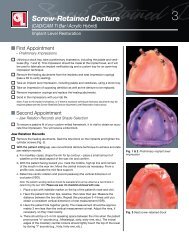
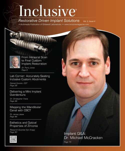
Inclusive®<br />
Restorative Driven Implant Solutions Vol. 2, Issue 4<br />
A Multimedia Publication of <strong>Glidewell</strong> Laboratories • www.inclusivemagazine.com<br />
From Intraoral Scan<br />
to Final Custom<br />
Implant Restoration<br />
Dr. Perry Jones<br />
Page 6<br />
Lab Corner: Accurately Seating<br />
Inclusive Custom Abutments<br />
Dzevad Ceranic, CDT<br />
Page 28<br />
Delivering a Mini Implant<br />
Overdenture<br />
Dr. Christopher Travis<br />
Page 36<br />
Mapping the Mandibular<br />
Canal with CBCT<br />
Dr. James Jesse<br />
Page 46<br />
Esthetics and Optical<br />
Properties of Zirconia<br />
Research Scientist Ken Knapp<br />
Page 50<br />
Implant Q&A:<br />
Dr. Michael McCracken<br />
Page 15
On the Web<br />
Here’s a sneak peek at additional Inclusive<br />
magazine content available online.<br />
ONLINE Video Presentations<br />
• Dr. Perry Jones demonstrates the all-digital restoration of an anterior<br />
case, from intraoral scanning to the CAD/CAM fabrication of<br />
all-zirconia custom abutments and a monolithic zirconia bridge.<br />
• Dr. Michael McCracken discusses the ability of dental implants<br />
to counteract bone resorption, as well as the various restorative<br />
options available today.<br />
• Dr. Christopher Travis outlines the proper procedure for delivering<br />
a newly fabricated mandibular overdenture retained by four<br />
mini implants.<br />
• Research scientist Ken Knapp explores the optical properties<br />
of partially stabilized zirconia and its future as a leading dental<br />
restorative material.<br />
Check out the latest issue of Inclusive<br />
magazine online or via your smartphone at<br />
www.inclusivemagazine.com.<br />
ONLINE CE credit<br />
• Get free CE credit for the material in this issue with each test you<br />
complete and pass. To get started, visit our website and look for<br />
the articles marked with “CE.”<br />
Look for these icons on the pages that follow for<br />
additional content available on our website,<br />
www.inclusivemagazine.com.<br />
– www.inclusivemagazine.com –
Contents<br />
6<br />
15<br />
From Intraoral Scan to Custom Implant Restoration<br />
Digital technology continues to revolutionize modern dentistry,<br />
benefitting every phase of treatment from diagnosis to final restoration.<br />
Here, Dr. Perry Jones demonstrates the use of an intraoral optical<br />
scanning system, followed by the CAD/CAM design and milling<br />
of all-zirconia custom abutments and a monolithic zirconia bridge,<br />
to precisely restore a historically problematic anterior case.<br />
Implant Q&A: Interview with Dr. Michael McCracken<br />
Ongoing studies have revealed correlations between tooth loss and<br />
systemic health issues such as gastrointestinal disorders, atherosclerosis,<br />
or even cancer. In this interview, prosthodontist and University<br />
of Alabama School of Dentistry professor Dr. Michael McCracken<br />
discusses the use of dental implants to stave off resorption, access to<br />
treatment, and various restorative options available today.<br />
ALSO IN THIS ISSUE<br />
21 Optimizing the Design of Zirconia<br />
Implant Abutments: A Finite Element<br />
Analysis<br />
28 Lab Corner: Accurately Seating<br />
Inclusive ® Custom Abutments Using<br />
an Acrylic Jig<br />
36<br />
46<br />
50<br />
Delivery of a Mini Implant-Retained Overdenture<br />
Though mini implants are designed to accommodate the immediate<br />
loading of an existing denture in the presence of primary stability,<br />
patients are often better served by the fabrication of a prosthesis<br />
specifically fitted for the new biologic form factor. Dr. Christopher<br />
Travis outlines the process of providing a new overdenture designed<br />
for optimal function and esthetics following the osseointegration of<br />
four mini implants.<br />
Implant and Mandibular Canal Mapping<br />
Three-dimensional CBCT images have a wide range of diagnostic<br />
and treatment planning uses, and are quickly becoming a standardof-care<br />
practice in implant planning. Using an illustrative case report,<br />
Dr. James Jesse describes how the latest 3-D imaging technology can<br />
help to produce safer, more predictable treatment outcomes.<br />
Zirconia Crown Esthetics and Optical Properties<br />
With their flexural strength, fracture toughness and toothlike esthetics,<br />
monolithic crowns & bridges milled from zirconia are increasingly<br />
being used as alternatives to traditional PFM restorations. In<br />
this scientific overview, <strong>Glidewell</strong> Laboratories’ Ken Knapp explains<br />
how the future of zirconia as a restorative material is rooted in the<br />
efforts of material scientists to engineer nanocrystalline structures<br />
that better approximate the optical translucency of natural dentition.<br />
– Contents – 1
Publisher<br />
Jim <strong>Glidewell</strong>, CDT<br />
Editor-in-Chief and clinical editor<br />
Bradley C. Bockhorst, DMD<br />
Managing Editors<br />
Jim Shuck; Mike Cash, CDT<br />
Creative Director<br />
Rachel Pacillas<br />
Contributing editors<br />
Greg Minzenmayer; Dzevad Ceranic, CDT;<br />
David Casper; Tim Torbenson<br />
copy editors<br />
Eldon Thompson, Jennifer Holstein, David Frickman<br />
digital marketing manager<br />
Kevin Keithley<br />
Graphic Designers/Web Designers<br />
Jamie Austin, Deb Evans, Joel Guerra,<br />
Audrey Kame, Lindsey Lauria, Phil Nguyen,<br />
Kelley Pelton, Melanie Solis, Ty Tran, Makara You<br />
Photographer/Clinical Videographers<br />
Sharon Dowd; James Kwasniewski, Marc Repaire,<br />
Sterling Wright<br />
Illustrator<br />
Phil Nguyen<br />
coordinatorS/AD Representatives<br />
Teri Arthur, Vivian Tsang<br />
If you have questions, comments or suggestions, e-mail us at<br />
inclusivemagazine@glidewelldental.com. Your comments may<br />
be featured in an upcoming issue or on our website.<br />
© 2011 <strong>Glidewell</strong> Laboratories<br />
Neither Inclusive magazine nor any employees involved in its publication<br />
(“publisher”) makes any warranty, express or implied, or assumes<br />
any liability or responsibility for the accuracy, completeness, or usefulness<br />
of any information, apparatus, product, or process disclosed, or<br />
represents that its use would not infringe proprietary rights. Reference<br />
herein to any specific commercial products, process, or services by<br />
trade name, trademark, manufacturer or otherwise does not necessarily<br />
constitute or imply its endorsement, recommendation, or favoring<br />
by the publisher. The views and opinions of authors expressed<br />
herein do not necessarily state or reflect those of the publisher and<br />
shall not be used for advertising or product endorsement purposes.<br />
CAUTION: When viewing the techniques, procedures, theories and<br />
materials that are presented, you must make your own decisions<br />
about specific treatment for patients and exercise personal professional<br />
judgment regarding the need for further clinical testing or education<br />
and your own clinical expertise before trying to implement new<br />
procedures.<br />
Inclusive is a registered trademark of <strong>Glidewell</strong> Laboratories.<br />
Letter from the Editor<br />
Turbulent economic times often motivate dentists to research<br />
and incorporate new means of maintaining, or even growing,<br />
their practices. One option is to expand service offerings. Mini<br />
implants might be a good choice. Once considered for transitional<br />
use only, small-diameter implants can provide a viable<br />
long-term solution in appropriate cases, at an affordable price.<br />
In this issue of Inclusive, we discuss access to dental care, as<br />
well as utilization of small-diameter implants, with Dr. Michael<br />
McCracken of the University of Alabama at Birmingham School<br />
of Dentistry. We also have a follow-up article on the fabrication<br />
of a mini implant overdenture by Dr. Christopher Travis. Online,<br />
you can view the case appointment-by-appointment from preliminary<br />
impressions to delivery of the final prosthesis.<br />
Another goal might be to incorporate products that reduce costs<br />
for both you and your patients. Due in part to the skyrocketing<br />
price of gold, all-ceramic restorations continue to gain in popularity.<br />
In fact, thanks to its high strength, low price point and<br />
patients’ demand for improved esthetics, monolithic BruxZir ®<br />
Solid Zirconia is the fastest-growing restoration in <strong>Glidewell</strong>’s<br />
history. Included are two articles from our R&D group: one on<br />
the optical properties of zirconia, and the other a finite element<br />
analysis of the Inclusive ® All-Zirconia Custom Abutment.<br />
As an adjunct to the abutment study, Dzevad Ceranic, CDT,<br />
reviews the fabrication and use of jigs as an aid to delivering<br />
abutments and screw-retained crowns easily and precisely.<br />
Newer technologies can also help you provide a higher quality<br />
of care to your patients while improving efficiencies. As a<br />
superior diagnostic tool, CBCT is becoming a standard of care<br />
for implant treatment. Dr. James Jesse reviews the use of this<br />
3-D imaging to accurately identify the mandibular canal, while<br />
Dr. Perry Jones demonstrates the use of intraoral scanning and<br />
CAD/CAM fabrication of an abutment and crown to deliver a<br />
model-free, implant-borne restoration.<br />
It is our hope that the information contained in this publication<br />
will provide insight into opportunities for strengthening your<br />
practice in these challenging times. Please enjoy the issue and<br />
take time to view the expanded content online.<br />
Dr. Bradley C. Bockhorst<br />
Editor-in-Chief, Clinical Editor<br />
inclusivemagazine@glidewelldental.com<br />
– Letter from the Editor – 3
Contributors<br />
■ Bradley C. Bockhorst, DMD<br />
After receiving his dental degree from Washington<br />
University School of <strong>Dental</strong> Medicine,<br />
Dr. Bradley Bockhorst served as a Navy <strong>Dental</strong><br />
Officer. Dr. Bockhorst is director of clinical<br />
technologies at <strong>Glidewell</strong> Laboratories, where<br />
he oversees Inclusive ® Digital Implant Treatment<br />
Planning services and is editor-in-chief<br />
and clinical editor of Inclusive magazine. A member of the<br />
CDA, ADA, AO, ICOI and the AAID, Dr. Bockhorst lectures internationally<br />
on an array of dental implant topics. Contact him<br />
at 800-521-0576 or inclusivemagazine@glidewelldental.com.<br />
■ VAHEH GOLESTANIAN, MSc<br />
Vaheh Golestanian received a master’s degree<br />
in biomedical engineering at Iran University<br />
of Science and Technology in Tehran. In 2008,<br />
he joined <strong>Glidewell</strong> Laboratories’ Implant R&D<br />
and Digital Manufacturing department as<br />
a manufacturing engineer. Vaheh has eight<br />
years’ experience as a mechanical engineer<br />
focused on finite element analysis and CNC programming,<br />
and is a member of the Society of Manufacturing Engineers.<br />
Contact him at inclusivemagazine@glidewelldental.com.<br />
■ Grant Bullis, MBA<br />
Grant Bullis, director of implant R&D and<br />
digital manufacturing at <strong>Glidewell</strong> Laboratories,<br />
began his dental industry career at<br />
Steri-Oss (now a subsidiary of Nobel Biocare)<br />
in 1997. Since joining the lab in 2007, Grant<br />
has been integral in obtaining FDA 510(k)<br />
clearances for the company’s Inclusive Custom<br />
Implant Abutments. In 2010, he was promoted to director<br />
and now oversees all aspects of CAD/CAM, implant product<br />
development and manufacturing. Grant has a degree in<br />
mechanical CAD/CAM from Irvine Valley College and an MBA<br />
from the Keller Graduate School of Management. Contact him<br />
at inclusivemagazine@glidewelldental.com.<br />
■ JAMES JESSE, DDS<br />
Dr. James Jesse graduated from Loma Linda<br />
University in 1973 and has been in private<br />
practice in Colton, Calif., for 34 years. An<br />
associate professor of restorative dentistry<br />
at LLU and an assistant professor of restorative<br />
dentistry at Columbia University, he is<br />
involved in research at both universities. Formerly<br />
a member of the executive board of the World Clinical<br />
Laser Institute and editorial board of Ascend Media, Dr. Jesse<br />
lectures nationally and internationally, and is a member of<br />
the ADA, AOD and AGD. Contact him at inclusivemagazine@<br />
glidewelldental.com.<br />
■ DZEVAD CERANIC, CDT<br />
Dzevad Ceranic began his career at <strong>Glidewell</strong><br />
Laboratories while attending Pasadena<br />
City College’s dental laboratory technology<br />
program. In 1999, Dzevad began working at<br />
<strong>Glidewell</strong> as a waxer and metal finisher, then<br />
as a ceramist. After being promoted to general<br />
manager of the Full-Cast department, he<br />
assisted in facilitating the lab’s transition to CAD/CAM.<br />
In June 2008, Dzevad took on the company’s rapidly growing<br />
Implant department, and in 2009 completed an eightmonth<br />
implants course at the UCLA School of Dentistry. Today,<br />
Dzevad leads a team of 170 people at the lab and continues to<br />
implement cutting-edge technology throughout his department.<br />
Contact him at inclusivemagazine@glidewelldental.com.<br />
■ Perry E. Jones, DDS, FAGD<br />
Dr. Perry Jones received his DDS from Virginia<br />
Commonwealth University School of Dentistry,<br />
where he has held adjunct faculty positions<br />
since 1976. He maintains a private practice in<br />
Richmond, Va. One of the first GP Invisalign ®<br />
providers, Dr. Jones has been a member of<br />
Align’s Speaker Team since 2002, presenting<br />
more than 250 Invisalign presentations. He has been involved<br />
with Cadent optical scanning technology since its release to<br />
the GP market and is currently beta testing the newest software<br />
from Align Technology. Dr. Jones belongs to numerous<br />
dental associations and is a fellow of the AGD. Contact him at<br />
inclusivemagazine@glidewelldental.com.<br />
4<br />
– www.inclusivemagazine.com –
■ Ken Knapp<br />
Ken Knapp joined <strong>Glidewell</strong> Laboratories in<br />
March 2008 as a program manager in the<br />
Materials Research and Development group.<br />
He has 30 years’ experience in the synthesis<br />
of magnetic and dental nanomaterials and<br />
microfabricated magnetic recording head<br />
devices. The last 10 years of his career have<br />
been focused on researching and developing nanostructured<br />
titanium dental devices and nanozirconia materials. Ken is<br />
an inventor on 23 U.S. patents in the areas of magnetic and<br />
dental nanostructured materials and devices. Contact him at<br />
inclusivemagazine@glidewelldental.com.<br />
■ David Leeson, MSc<br />
David Leeson received a first class honors<br />
degree in manufacturing engineering from<br />
England’s Loughborough University, followed<br />
by a Master of Science in advanced automation<br />
and design from Cranfield University.<br />
After graduation, he worked in the motorsports<br />
industry, creating manufacturing processes<br />
for high-precision racing engines. David is currently senior<br />
manufacturing engineer in <strong>Glidewell</strong> Laboratories’ Implant<br />
R&D and Digital Manufacturing department. After joining<br />
<strong>Glidewell</strong> in January 2007, he used his engineering background<br />
to launch many new products, including titanium and<br />
zirconia abutments, as well as implant bars. He also led the<br />
development of <strong>Glidewell</strong>’s automated machining capability.<br />
Contact him at inclusivemagazine@glidewelldental.com.<br />
■ CHRISTOPHER P. TRAVIS, DDS<br />
Dr. Christopher Travis received his dental<br />
degree and certificate in prosthodontics from<br />
USC School of Dentistry, where he served as<br />
an assistant clinical professor in predoctoral<br />
and graduate prosthodontics. For the past<br />
30 years, he has maintained a full-time private<br />
practice specializing in prosthodontics in<br />
Laguna Hills, Calif. Dr. Travis is director of the Charles Stuart<br />
Study Group in Laguna Hills, prosthodontic coordinator for<br />
the Newport Harbor Academy of Dentistry, and active member<br />
of the Pacific Coast Society for Prosthodontics, American<br />
College of Prosthodontists and AO, as well as a Fellow of the<br />
ACD. Contact him at 949-683-7456 or surfnswim@fea.net.<br />
■ Weihan Zhang, Ph.D<br />
Weihan Zhang graduated from the University<br />
of Missouri-Rolla (now Missouri University<br />
of Science and Technology) in 2008 with a<br />
Ph.D in mechanical engineering. Since joining<br />
<strong>Glidewell</strong> Laboratories in 2008, Weihan<br />
has been actively involved in software development,<br />
prototyping machine and system<br />
development projects as a manufacturing software engineer.<br />
He has also published more than 20 articles on geometric<br />
modeling and manufacturing engineering. Contact him at<br />
inclusivemagazine@glidewelldental.com.<br />
■ Michael McCracken, DDS, Ph.D<br />
After completing dental school at the University<br />
of North Carolina at Chapel Hill and a prosthodontic<br />
residency at University of Alabama at<br />
Birmingham, Dr. Michael McCracken received<br />
a Ph.D in biomedical engineering for research<br />
related to growth factors and healing of implants<br />
in compromised hosts. Dr. McCracken is<br />
a professor in the department of general dental sciences at UAB<br />
School of Dentistry, where he has also served as associate dean<br />
for education, director of graduate prosthodontics, and director<br />
of the implant training program. He maintains an active<br />
research program within the university and a private practice<br />
focused on implant dentistry. He also lectures internationally.<br />
Contact him at inclusivemagazine@glidewelldental.com.<br />
– Contributors – 5
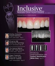
From Intraoral Scan to<br />
Final Custom Implant Restoration<br />
Go online for<br />
in-depth content<br />
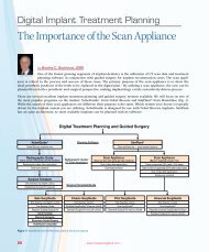
by Perry E. Jones, DDS, FAGD<br />
Introduction<br />
This case demonstrates the optical scanning of <strong>Glidewell</strong> Laboratories’ purpose-made Inclusive ®<br />
Scanning Abutments utilizing the iTero digital scanning system (Align Technology; San Jose, Calif.)<br />
with software version 4.0. Digital data was used in conjunction with laboratory CAD/CAM planning to<br />
fabricate custom all-ceramic implant abutments and a final 4-unit fixed prosthesis. The abutments and<br />
fixed prosthesis were fabricated using advanced computer-aided milling technology.<br />
Editor’s note: Cadent Inc. (Carlstadt, N.J.) was acquired by Align Technology (San Jose, Calif.) in May 2011.<br />
6<br />
– www.inclusivemagazine.com –
<strong>Dental</strong> History<br />
The patient in this case was a 52-year-old healthy Hispanic<br />
male who sustained a traumatic avulsion and loss of his<br />
maxillary incisors in an automobile accident. Following<br />
healing, the patient reported that a 4-tooth transitional<br />
removable partial denture was constructed. He was seen<br />
by the oral and maxillofacial surgery service of Virginia<br />
Commonwealth University, as he desired dental implant<br />
therapy. The patient reported multiple incidents of a<br />
“broken” provisional denture (Fig. 1).<br />
Treatment Plan<br />
The patient was informed of the alternatives, benefits and<br />
potential complications of various treatment options before<br />
confirming his desire to pursue implant restoration<br />
of his missing anterior teeth. The treatment plan included<br />
placement of two Replace ® Select Straight RP 4.3 x 13 mm<br />
implants (Nobel Biocare; Yorba Linda, Calif.) with 5 mm<br />
healing abutments, followed by a six-month healing period<br />
and restoration with all-zirconia custom abutments and a<br />
4-unit all-ceramic fixed prosthesis to restore the anterior<br />
incisors to form and function.<br />
Surgical Procedure<br />
Using local anesthesia, two Replace Select Straight RP implant<br />
fixtures were placed in the area of tooth #7 and #10<br />
using standard Nobel Biocare implant placement protocol.<br />
Placement angulation and depth were verified and appeared<br />
to be satisfactory (Fig. 2). Standard RP 5 mm healing<br />
abutments were placed, and the fully reflected tissue flap<br />
was closed with interrupted sutures (Fig. 3).<br />
Figure 1: Patient presents with broken RPD. Note tight anterior coupling.<br />
Figure 2: Osteotomies for implants #7 and #10 with guide pins<br />
The patient was informed of the<br />
alternatives, benefits and potential<br />
complications of various treatment<br />
options before confirming his<br />
desire to pursue implant restoration<br />
of his missing anterior teeth.<br />
Figure 3: Post placement with 5 mm healing abutments and sutures<br />
– From Intraoral Scan to Final Custom Implant Restoration – 7
Figure 4: Healing abutments at six months post implant placement<br />
Figure 5: Right buccal view<br />
Figure 6: Left buccal view<br />
Figure 7: Maxillary occlusal view<br />
Figure 8: Mandibular occlusal view<br />
Figure 9: Panoramic view of implants at six months<br />
Restorative Procedure<br />
Following six months of healing post implant placement,<br />
intraoral photos were taken to record and confirm<br />
the healthy remaining dentition (Figs. 4–8). Osseous integration<br />
was confirmed with a panoramic X-ray (Fig. 9),<br />
followed by resonance frequency analysis (RFA) using an<br />
Osstell ® ISQ implant stability meter with SmartPeg attachment<br />
(Osstell Inc. USA; Linthicum, Md.) (Fig. 10), which<br />
displayed an implant stability quotient (ISQ) of 78 on a<br />
8<br />
– www.inclusivemagazine.com –
Figure 10: Osstell ISQ implant stability meter<br />
Figure 11: Replace Select Straight RP implants (Nobel Biocare)<br />
with healing abutments<br />
The 5 mm healing abutments<br />
were removed and purpose-made<br />
Inclusive Scanning Abutments were<br />
placed and hand-tightened over the<br />
implants with the accompanying<br />
titanium screws.<br />
Figure 12: Inclusive Scanning Abutment with attachment screw<br />
Figure 13: Inclusive Scanning Abutments attached to implants (occlusal view)<br />
Figure 14: Inclusive Scanning Abutments attached to implants (labial view)<br />
minimum-to-maximum scale of 1–100. Counter rotation<br />
with a torque wrench confirmed no rotation to 35 Ncm.<br />
Based on this evidence of stability, the implant fixtures<br />
were deemed to be acceptable for restoration.<br />
The 5 mm healing abutments were removed (Fig. 11) and<br />
purpose-made Inclusive Scanning Abutments (Fig. 12) were<br />
placed and hand-tightened over the implants with the<br />
accompanying titanium screws (Figs. 13, 14).<br />
– From Intraoral Scan to Final Custom Implant Restoration – 9
Figure 15: iTero virtual scan (Align Technology)<br />
Figure 16: Registering scanning abutment library to iTero virtual scan<br />
Figure 17: Scanning abutments registered to iTero virtual scan<br />
Figure 18: Abutment planning (labial view) with 3Shape's<br />
<strong>Dental</strong>Designer software and Prismatik CZ add-on module<br />
The treatment plan included …<br />
restoration with all-zirconia<br />
custom abutments and a 4-unit<br />
all-ceramic fixed prosthesis to<br />
restore the anterior incisors<br />
to form and function.<br />
Figure 19: Abutment design (occlusal view)<br />
Using the iTero scanner with updated software (version 4.0),<br />
a full maxillary arch scan, full mandibular arch scan and<br />
centric bite in maximum intercuspation were completed.<br />
A three-dimensional digital record of the patient’s anatomy<br />
was created from these scans (Fig. 15) and electronically<br />
submitted to <strong>Glidewell</strong> Laboratories to be used in the CAD/<br />
CAM restoration process.<br />
At <strong>Glidewell</strong> Laboratories, the virtual scan was registered to<br />
the scanning abutments (Figs. 16–17). This provides the dental<br />
technicians with the implant system, size, axis, position relative<br />
to the adjacent anatomy and locking feature orientation.<br />
A virtual zirconia abutment was designed using 3Shape’s<br />
<strong>Dental</strong>Designer software (3Shape Inc.; New Providence,<br />
N.J.) and the <strong>Glidewell</strong> Digital Abutment Library (Figs. 18–21).<br />
10<br />
– www.inclusivemagazine.com –
Figure 20: Abutment design (profile view)<br />
Figure 21: Abutment design (lingual view)<br />
A virtual zirconia abutment<br />
was designed using 3Shape’s<br />
<strong>Dental</strong>Designer software and the<br />
<strong>Glidewell</strong> Digital Abutment Library.<br />
From this ... Inclusive All-Zirconia<br />
Custom Abutments were milled.<br />
Figure 22: Inclusive All-Zirconia Custom Abutments #7 and #10<br />
Figure 23: Inclusive All-Zirconia Custom Abutment #7<br />
Figure 24: Inclusive All-Zirconia Custom Abutment #10<br />
From this, the corresponding physical Inclusive All-Zirconia<br />
Custom Abutments (<strong>Glidewell</strong> Laboratories) were milled.<br />
Similarly, a BruxZir ® Solid Zirconia 4-unit fixed bridge<br />
(<strong>Glidewell</strong> Laboratories) was designed and milled using this<br />
state-of-the-art CAD/CAM technology.<br />
The custom zirconia abutments were trial-fitted in the<br />
patient’s mouth with some slight tissue blanching noted<br />
(Fig. 22). The individual close-up views demonstrate how<br />
close the labial path of insertion passed to the head of each<br />
abutment’s titanium screw (Figs. 23, 24).<br />
– From Intraoral Scan to Final Custom Implant Restoration – 11
Figure 25: 4-unit BruxZir Solid Zirconia fixed bridge (labial view)<br />
Figure 26: 4-unit BruxZir Solid Zirconia fixed bridge<br />
(internal abutment view)<br />
Figure 27: 4-unit BruxZir Solid Zirconia fixed bridge (labial view)<br />
Figure 28: 4-unit BruxZir Solid Zirconia fixed bridge (occlusal view)<br />
Figure 29: Final all-zirconia restoration<br />
Figure 30: Happy patient!<br />
12<br />
– www.inclusivemagazine.com –
In the same visit, the completed 4-unit all-ceramic milled<br />
BruxZir Solid Zirconia bridge was trial-fitted and examined<br />
for proper occlusion (Figs. 25, 26). There was “tight” anterior<br />
coupling for this case as evidenced by the history of provisional<br />
denture fracture. The occlusion was checked and<br />
presented as so precise that no adjustment was required.<br />
The anterior view of the final prosthesis demonstrates optimal<br />
mesial-distal width proportion, incisal edge proportion,<br />
pontic-tissue contact and excellent shade/esthetics (Fig. 27).<br />
Further, the occlusal view demonstrates an optimal incisal<br />
edge arch form (Fig 28). The soft tissue lip position and<br />
speech phonetics appeared to be optimal (Fig. 29). Following<br />
the trial fitting, the fixed bridge was removed, the zirconia<br />
abutment retention screws torqued to 35 Ncm, the abutment<br />
screws covered with cotton/Cavit Temporary Filling<br />
Material (3M ESPE ; St. Paul, Minn.), and the prosthesis<br />
cemented with GC Fuji PLUS (GC America; Alsip, Ill.).<br />
The final full-face photo demonstrates the pleasing smile<br />
achieved with the restorative result (Fig. 30). IM<br />
General References<br />
• Baldissara P, Llukacej A, Ciocca L, Valandro FL, Scotti R. Translucency of zirconia<br />
copings made with different CAD/CAM systems. J Prosthet Dent. 2010<br />
Jul;104(1):6-12.<br />
• Birnbaum NS, Aaronson HB. <strong>Dental</strong> impressions using 3D digital scanners: virtual<br />
becomes reality. Compend Contin Educ Dent. 2008 Oct;29(8): 494, 496, 498-505.<br />
• Chang YB, Xia JJ, Gateno J, Xiong X, Zhou X, Wong ST. An automatic and robust<br />
algorithm of reestablishment of digital dental occlusion. IEEE Trans Med Imaging.<br />
2010 Sep;29(9):1652-63.<br />
• Christensen GJ. Will digital impressions eliminate the current problem with conventional<br />
impressions? J Am Dent Assoc. 2008 Jun;139(6):761-3.<br />
• Drago C, Saldarriaga RL, Domagala D, Almasri R. Volumetric determination of the<br />
amount of misfit in CAD/CAM and cast implant frameworks: a multicenter laboratory<br />
study. Int J Oral Maxillofac Implants. 2010 Sep-Oct;25(5):920-9.<br />
• Ender A, Mehl A. Full arch scans: conventional versus digital impressions — an<br />
in-vitro study. Int J Comput Dent. 2011;14(1):11-21.<br />
• Fasbinder DJ. Digital dentistry: innovation for restorative treatment. Compend<br />
Contin Educ Dent. 2010;31(4):2-11.<br />
• Garg AK. Cadent iTero’s digital system for dental impressions: the end of trays and<br />
putty? Dent Implantol Update. 2008 Jan;19(1): 1-4.<br />
• Jones PE. Cadent iTero digital impression case study: full-arch fixed provisional<br />
bridge. DC <strong>Dental</strong>compare. 2009 Jul 8 [cited 2011 Jul 28]. Available from:<br />
http://www.dentalcompare.com/Featured-Articles/2082-Cadent-iTero-Digital-<br />
Impression-Case-Study-Full-Arch-Fixed-Provisional-Bridge/.<br />
• Jones PE. Cadent iTero optical scanning digital impressions for restorative and<br />
invisalign. <strong>Dental</strong> Product Shopper. 2011 Jun 28 [cited 2011 Jul 29]. Available from:<br />
http://dentalproductshopper.reachlocal.net/articles/cadent-itero-optical-scanningdigital-impressions-restorative-and-invisalign.<br />
• Kurbad A. Impression-free production techniques. Int J Comput Dent.2011;14(1):<br />
59-66.<br />
• Priest G. Virtual-designed and computer-milled implant abutments. J Oral Maxillofac<br />
Surg. 2005 Sep;63(9 Suppl 2):22-32.<br />
• Smith R. Creating well-fitting restorations with a digital impression system.<br />
Compend Contin Educ Dent. 2010 Oct;31(8):640-4.<br />
• Touchstone A, Nieting T, Ulmer N. Digital transition: the collaboration between<br />
dentists and laboratory technicians on CAD/CAM restorations. J Am Dent Assoc.<br />
2010;141 Suppl 2:15S-9S.<br />
• Zweig A. Improving impressions: go digital! Dent Today. 2009 Nov;28(11):100, 102,<br />
104.<br />
– From Intraoral Scan to Final Custom Implant Restoration – 13
Implant Q&A:<br />
An Interview with<br />
Dr. Michael McCracken<br />
Go online for<br />
in-depth content<br />
Interview of Michael McCracken, DDS, Ph.D<br />
by Bradley C. Bockhorst, DMD<br />
Dr. Michael McCracken is a prosthodontist<br />
and a professor at the University of Alabama<br />
School of Dentistry. He maintains an active<br />
research program within the university, as well<br />
as a private practice in Birmingham focused<br />
on implant dentistry. He sat down to discuss<br />
his practical approach to this field of dentistry<br />
during a recent visit to the <strong>Glidewell</strong> International<br />
Technology Center.<br />
– Implant Q&A: An Interview with Dr. Michael McCracken – 15
Dr. Bradley Bockhorst: Today, Mike, I’d like to talk<br />
about one of the things that is near and dear to your<br />
heart: the health effects of edentulism. Why don’t you<br />
go ahead and tell us a little bit about what you’ve been<br />
doing along that line, both at UAB School of Dentistry<br />
and professionally.<br />
Dr. Michael McCracken: Thanks, Brad. It’s nice to<br />
be here. We have been learning a lot about edentulism<br />
in the last 10 years or so. We are realizing how health<br />
can be affected by the oral state, and how somebody<br />
losing their teeth will lead to all kinds of systemic<br />
problems, such as atherosclerosis or cancer. People<br />
who have a denture, or who have a poor denture, take<br />
a lot more GI medicine. So we are looking at ways that<br />
we can treat that as a dental community. I think it’s an<br />
exciting time to be in dentistry because now we have<br />
implants. Now we have options that we didn’t have<br />
many years ago that we can offer to patients. Instead<br />
of telling them they have to have a denture, we can<br />
offer them some valuable alternatives.<br />
BB: One of the challenges we face as dentists is that<br />
it’s our obligation to communicate to our edentulous<br />
patients what is going on as far as bone loss. Maybe<br />
you can share your thoughts along that line.<br />
MM: I think about that sometimes. We know that one<br />
of the leading lawsuits against dentists is the failure<br />
to diagnose periodontal disease. So a patient goes to<br />
their dentist whom they’ve gotten along well with for<br />
20 years, and they’ve been going in every six months<br />
for their checkup. They’ve been doing what they think<br />
they should be doing on their side. Then one day the<br />
dentist walks in and says: “Well, I’m sorry. You have<br />
periodontal disease. And now you’re going to have to<br />
lose these teeth, or you’re going to have to have this<br />
surgery, or have these implants placed.” Understandingly,<br />
the patient is upset by this and says: “Why didn’t<br />
We know that one of<br />
the leading lawsuits<br />
against dentists is the<br />
failure to diagnose<br />
periodontal disease.<br />
We are realizing how<br />
health can be affected by<br />
the oral state, and how<br />
somebody losing their<br />
teeth will lead to all kinds<br />
of systemic problems.<br />
you ever tell me about periodontal disease? Why didn’t<br />
you ever tell me I had this disease in my mouth?”<br />
They’re upset, and this causes some problems.<br />
Sometimes I wonder: Will we see that with the edentulous<br />
patient? Because now we have a similar situation.<br />
We have a patient who has been going to a dentist<br />
for 20 years. Maybe they come in every year or two<br />
for a checkup or a denture adjustment. And then all<br />
of a sudden they have problems with a mandibular<br />
fracture, or they have a situation where they can no<br />
longer successfully wear a lower denture, or they are<br />
experiencing something else related to bone loss. And<br />
maybe they’re going to ask their dentist: “Why didn’t<br />
you ever tell me about this bone loss? Why didn’t you<br />
ever tell me this was going on? Why didn’t you tell me<br />
about this disease?” Because now we can effectively<br />
treat that with implants.<br />
BB: If dentists are not involved with implants, for<br />
whatever reason, do they have an obligation to offer<br />
them as an option to these patients to stop that potential<br />
bone loss?<br />
MM: Absolutely. Clearly, whether you offer those services<br />
in your office, or you refer to a surgeon for implant<br />
placement, the option has to be offered to the<br />
patient. They just need to understand what’s going on.<br />
We have some patients who learn the hard way the<br />
effects of bone loss. As an example, we had a lady<br />
who, after being edentulous for many, many years, had<br />
her mandible resorb and resorb, becoming the size of<br />
a pencil. She breaks her mandible as she is walking<br />
out to the pool — stepped too hard, hit her jaw, and<br />
now she has a fracture. It’s a very difficult revision<br />
surgery — usually bilateral hip grafts — and quite a<br />
bit of hospital experience. A lot a money and a lot of<br />
16<br />
– www.inclusivemagazine.com –
Not only are we<br />
maintaining the bone<br />
between the implants,<br />
we are actually getting<br />
bone maintenance or a<br />
bone gain of up to<br />
2 mm on average<br />
behind the implant.<br />
morbidity come with that when, if somebody had just<br />
told her at the right time that they needed to put some<br />
implants in there to maintain her bone levels, she<br />
would’ve been much better off. Then it’s not a hospital<br />
procedure; it’s an in-office procedure — very simple.<br />
Instead of three days in the hospital, you have three<br />
hours in the dental chair.<br />
BB: Are there any studies or any research coming out<br />
of UAB School of Dentistry that are related to being<br />
able to maintain that bone level, or even in some cases<br />
potentially increase it?<br />
MM: Yes. And we did see an increase in bone levels,<br />
surprisingly to me, in a study that was done by the<br />
periodontists at UAB, which was a prospective clinical<br />
trial, long-term, about eight years. And we restored<br />
these patients with five implants in the anterior mandible<br />
and a very traditional Brånemark style, with about<br />
3 mm between the prosthesis and the edentulous<br />
ridge. We noticed over time — this was back in the<br />
nineties — that the tissue would proliferate and touch<br />
the bottom of the bridge. The periodontist thought<br />
we had better clean that up or take that down, so the<br />
patient would have access to clean. When they went in<br />
there to remove that soft tissue, it wasn’t soft tissue; it<br />
was bone. So we measured that as part of this clinical<br />
trial, and we saw 1.5 mm, some patients 2 to 3 mm,<br />
of bone gain distal to the implant. So not only are we<br />
maintaining the bone between the implants, we are<br />
actually getting bone maintenance or a bone gain<br />
of up to 2 mm on average behind the implant. So as<br />
we are adding stress back to this system, the bone is<br />
responding by increasing in volume and density.<br />
BB: That leads into one of your other primary interests:<br />
talking to patients about bone loss, and giving them<br />
solutions that are affordable. Maybe you can share<br />
with us a little bit about what you’ve done at the school<br />
as far as low-cost options for restoring these patients.<br />
MM: Certainly. I do think that is critically important. If<br />
we believe that implants are important, as we do as a<br />
profession, then how can we help more of our patients<br />
get into implants? How can we assist our patients,<br />
let them experience implant dentistry and enjoy those<br />
benefits? At the school, we have developed a lowcost<br />
program that we have offered to our patients.<br />
Of course, keep in mind it’s a dental school, and we<br />
have students working on these. But we have provided<br />
the two-implant overdenture, which is just a basic,<br />
entry-level implant prosthesis. We give them the two<br />
implants, the two dentures and the two attachments<br />
for around $1,500. Most people we find can get into<br />
that with a little bit of desire. Most patients are very<br />
satisfied with that price point, and we are able to help<br />
them maintain their bone, get rid of a complete denture<br />
and move into an implant-supported prosthesis.<br />
BB: I believe you’re also doing some ongoing work<br />
with 3 mm diameter implants?<br />
MM: We are. To me, this is an interesting potential solution<br />
to some of the costs associated with traditional<br />
implant systems: single-piece overdenture implants.<br />
These are available generally in different sizes, around<br />
3 mm or a little smaller. We wanted to make sure that<br />
this treatment modality was going to be successful<br />
for our patients. We did a clinical trial with about 45<br />
patients, and we randomized those to two, three or<br />
four 3 mm diameter implants in the mandible. I was<br />
really surprised at the results. I’m generally conservative<br />
when it comes to loading protocols, time and so<br />
forth. Obviously, with a one-piece implant, you can’t<br />
have delayed loading. So we had immediate loading at<br />
the time of placement, and we had a relatively smalldiameter<br />
implant. Clinically, the results were excellent.<br />
I’m gaining much confidence in this treatment<br />
modality.<br />
BB: I know the results haven’t been published yet, but<br />
do you have a preference for the number of implants<br />
— two, three, four? Typically when we start getting into<br />
the smaller diameters, they’re saying four implants in<br />
the symphysis. What is your take on this?<br />
– Implant Q&A: An Interview with Dr. Michael McCracken – 17
We found no difference<br />
between two or four<br />
implants, in terms of<br />
implant survival or bone<br />
loss around the implants.<br />
MM: That was the main question: Do you have to do<br />
four? Because if you’re going for a low-cost alternative,<br />
it would be cheaper to do two. And, indeed, we found<br />
no difference between two or four implants, in terms<br />
of implant survival or bone loss around the implants.<br />
So two implants, in our study, worked very well.<br />
BB: Some people call the 3.0 implants “hybrids” because<br />
they are getting close to that conventional diameter,<br />
as opposed to the very narrow implants — the true<br />
small diameters. Would you have a different approach<br />
if you went smaller than a 3.0?<br />
MM: I’ve still been a little nervous about the smallerdiameter<br />
implants. I just haven’t had a lot of clinical<br />
experience with them myself, coming from a more<br />
conventional approach with standard-diameter implants.<br />
But the results that we got from the 3.0 are<br />
encouraging me to try something a little bit more narrow,<br />
because there are times when that’s very helpful.<br />
I mean, many patients have a narrow ridge, and you’re<br />
faced with the clinical decision of, am I going to remove<br />
6 or 7 mm of bone height so I can get sufficient<br />
width for my implant? Or am I going to simply place a<br />
small-diameter implant? I think maybe we’ll be going<br />
more toward the direction of the smaller implants as<br />
we move forward with this.<br />
BB: On the subject of bundling prices to get implant<br />
treatment to an affordable level for patients, you mentioned<br />
bundling two implants, two dentures and two<br />
attachments. Do you have something else if you’re going<br />
to do four 3.0? Have you gotten into a bundle for<br />
that, or is that still a work in progress?<br />
MM: For the students, it’s still a work in progress. For<br />
my own practice, I think that is very exciting. I love<br />
what <strong>Glidewell</strong> has done with the package concept<br />
because it really simplifies things for me as a clinician<br />
to know: This is your cost, these are your implants, get<br />
the overdenture for that. Then I can translate that into<br />
a clinical situation with a patient who really wants to<br />
get implants, and who I really want to get into implants.<br />
It simplifies things for everybody. I definitely<br />
plan to pass those cost savings on to the patients.<br />
BB: I understand that outside of the dental school, you<br />
are getting involved in a community clinic. Do you<br />
want to share a little bit of why you got involved with<br />
that and what your plans are with it?<br />
MM: Sure. We set up a community clinic outside of<br />
Birmingham. We’re associated with a drug-addiction<br />
recovery program down there, but we’re also open for<br />
community patients who don’t have much access to<br />
care. And I have to say, it is one of the most rewarding<br />
things I do — even with being a teacher, which is rewarding<br />
in itself. To help people who don’t have other<br />
avenues for dental work is extremely exciting. It’s a<br />
big volunteer effort from a number of organizations<br />
down there involved with that. But we’re planning on<br />
offering them the best dentistry we can, and that’s definitely<br />
going to include implants.<br />
BB: That ties right into bundled pricing, where you<br />
can offer services at very affordable prices.<br />
MM: That’s right. We have a lot of edentulous folks in<br />
Alabama — sixth highest in the States is our ranking<br />
now, I believe. So we have plenty of people needing<br />
implant overdentures.<br />
BB: Do you know what the percentage is?<br />
MM: For our seniors, age 65 and over, it’s more than<br />
30 percent now in Alabama that are edentulous. And<br />
that’s fairly consistent with other states.<br />
BB: We’ve talked a lot about restoring the lower edentulous<br />
ridge. What do you typically do in the maxilla?<br />
MM: The maxilla is a little more of a challenge. The<br />
bone is less dense, of course, and the implants are less<br />
predictable in the maxilla. I’ve always been an advocate<br />
of multiple implants tied together — be it with a<br />
bar, be it with a fixed prosthesis. But lately I’ve had<br />
success with individual implants and a cobalt chromium<br />
framework to give structure to the prosthesis, so<br />
that we have some form of cross-arch stabilization and<br />
some splinting from that rigid metal framework. So in<br />
the maxilla, now I’m moving more toward four implants<br />
with attachments using that metal substructure.<br />
18<br />
– www.inclusivemagazine.com –
BB: If you go that route — four implants and a cast<br />
framework — are you going palate-less, or are you still<br />
doing complete palatal coverage?<br />
MM: I have to say I’m about fifty-fifty on it. Occasionally<br />
I’ll take the palate out. I think that’s pushing the<br />
limits a little bit. I certainly see that it works in some<br />
patients, but I try to talk the patients into a palate. I<br />
think it gives me more comfort than anything else.<br />
BB: Another study coming?<br />
MM: That would be a great study — six implants, no<br />
worries.<br />
BB: Is there anything else exciting going on at the<br />
school or for you personally?<br />
MM: Tough question. I was walking through <strong>Glidewell</strong><br />
Laboratories, and I’m really excited about the<br />
milled BioTemps ® that are coming out now. They look<br />
beautiful. I’ve always been thrilled with BioTemps, the<br />
pricing and the esthetics, especially long-term. As a<br />
prosthodontist I have patients’ cases for 12, 15 months<br />
waiting for grafting or whatever, and the BioTemps<br />
have held up really well for me. I like the milled<br />
approach they’re taking now. It just seems to be a neat<br />
technological advancement.<br />
BB: Yes. Everything is going CAD/CAM. It provides a<br />
more predictable, consistent result.<br />
MM: I think it won’t be too long from now when I can<br />
just take a scan of the arch, not even have to make a<br />
cast, and you guys can send me a BioTemps full arch.<br />
BB: Yes, that’s coming. Let’s step back a minute and<br />
talk about your thoughts on cone-beam scanning,<br />
on using it as a diagnostic tool for those edentulous<br />
patients. Do you do it just for diagnostic purposes? Do<br />
you head toward guided surgery? When would you<br />
use a guide versus doing a flap?<br />
MM: For me, I find that a flap is useful in many of my<br />
surgical approaches. That may be because I need to<br />
manipulate the soft tissue. I may need a grafting in a<br />
certain situation. We may need to thicken the soft tissue.<br />
So, for a variety of reasons, I find that I’m laying a<br />
lot of flaps. For the perfect patient with abundant bone<br />
and abundant keratinized tissue, there’s nothing easier<br />
than a guided surgery. With a placement, to have the<br />
confidence and predictability of knowing the anatomy,<br />
you can’t beat that, knowing that your implant is going<br />
to come out in the right spot.<br />
BB: At the school, are you guys routinely CT scanning<br />
those patients?<br />
MM: Routinely? No. For me, if the patient has abundant<br />
bone, I don’t really need to scan. If the patient<br />
has very inadequate bone, sometimes I don’t need to<br />
scan to tell. I know I need to graft. It’s the patients<br />
in the middle, certainly large cases, where CBCT is a<br />
great help — especially for the patients where you really<br />
don’t know what your approach is going to be. Do<br />
we need to graft? Can we place the implant and graft<br />
simultaneously? Many of these questions are answered<br />
with a cone-beam scan.<br />
BB: We talked about the health effects of edentulism<br />
and keeping patients informed of implants as an option,<br />
particularly implants and prosthetics on top of<br />
them as an affordable option. Do you have any final<br />
thoughts or comments on this?<br />
MM: I think we should be using the fixed prosthesis<br />
more. I see a lot of people who are very comfortable<br />
with the two-implant overdenture, the four-implant<br />
overdenture. I think the fixed prosthesis, a traditional<br />
Brånemark hybrid prosthesis, is one of the best things<br />
we can do for folks, and I’d love it if we were doing a<br />
lot more.<br />
BB: How many implants do you usually like to do for<br />
your hybrids?<br />
MM: Traditionally, I like five, but I’m very comfortable<br />
with four. They can be straight. They don’t have to<br />
be tilted. The literature clearly supports four implants<br />
in the anterior mandible. And, just recently, I read an<br />
article that showed good success on three. So maybe<br />
we are even pushing the limit in that direction as well.<br />
But I think four or five implants is very reasonable.<br />
BB: OK, great. So what do they say in ’Bama?<br />
MM: Roll Tide.<br />
BB: There you go. IM<br />
– Implant Q&A: An Interview with Dr. Michael McCracken – 19
Optimizing the Design of Zirconia Implant<br />
Abutments: A Finite Element Analysis<br />
by Vaheh Golestanian, MSc; David Leeson, MSc;<br />
Grant Bullis, MBA; and Weihan Zhang, Ph.D<br />
INTRODUCTION<br />
Esthetic concerns are essential for anterior tooth restorations. Zirconia is a widely used engineering ceramic considered to<br />
have high load strength and fracture toughness compared to other ceramic materials used in dentistry. It is also a highly<br />
biocompatible ceramic material less prone to discoloring the cervical soft tissues than metal abutments. 1 Zirconia, like other<br />
ceramics, is sensitive to tensile stresses and extreme care must be taken to design the prosthetic connection to the implant<br />
so that tensile stresses are minimized. Manufacturing small, high-precision components from zirconia is challenging, and it<br />
requires rigorous attention to detail in every aspect of the manufacturing process. Small defects introduced during manufacturing<br />
can lead to fractures, and poor tolerance control can lead to rotational play between abutment and implant, which<br />
can result in loosening of the abutment’s retaining screw. 2,3<br />
– Optimizing the Design of Zirconia Implant Abutments: A Finite Element Analysis – 21
For proper prosthetic function, zirconia abutments must<br />
exhibit performance characteristics comparable to those<br />
of traditional titanium abutments. 4 Zirconia has a higher<br />
compressive strength compared to titanium alloy. However,<br />
under cyclic loading situations, zirconia abutments will<br />
fracture when overloaded, while a titanium abutment will<br />
undergo plastic deformation. ISO 14801:2007 is the fatigue<br />
testing standard for endosseous dental implants. 5 With this<br />
procedure, the implant and abutment assembly is cyclically<br />
loaded to determine its fatigue limit. The fatigue limit<br />
will be reached at lower loads if the prosthetic connection<br />
geometries of zirconia abutments are left identical to titanium,<br />
rather than being optimized for the intrinsic material<br />
properties of zirconia.<br />
METHODS AND MATERIALS<br />
The initial abutment design used in this study was <strong>Glidewell</strong><br />
Laboratories’ titanium abutment CAD model. A threedimensional<br />
finite element model was generated from the<br />
abutment and implant by importing these CAD models into<br />
COSMOSWorks software (Fig. 1). For simplicity, the implant<br />
threads were removed and the abutment screw was modeled<br />
by beam elements.<br />
The implant material was defined as commercially pure<br />
titanium, grade 4. The abutment screw material was<br />
defined as Ti-6AL-4V titanium alloy, and was tightened to<br />
35 Ncm torque.<br />
Since repeated cyclic loading of implants induces plastic<br />
deformation, it is normally recommended to conduct a<br />
nonlinear finite element analysis. 6 However, in this study,<br />
a linear analysis was performed as a simplification. This<br />
assumption is justified by the following:<br />
1. The maximum applied force (250 N) produces a very<br />
small region of plastic deformation on the implant,<br />
so the deviation between linear and nonlinear analysis<br />
would be relatively small and adequate for design<br />
optimization, but not an absolute indication of the<br />
strength of the abutment.<br />
2. Contact analysis is possible in linear mode with COS-<br />
MOSWorks. It was assumed that the relative movement<br />
between abutment and implant would be negligible<br />
and would not significantly affect the analysis results.<br />
The model was restrained from the implant’s body, 3 mm<br />
beneath the contact face of the abutment and implant, and<br />
a static, oblique force of 250 N was applied at a 30-degree<br />
For proper prosthetic<br />
function, zirconia abutments<br />
must exhibit performance<br />
characteristics comparable<br />
to those of traditional<br />
titanium abutments.<br />
Figure 1: CAD model of the abutment<br />
22<br />
– www.inclusivemagazine.com –
angle to the long axis of the implant. Three-dimensional<br />
tetrahedral solid elements were used to mesh the abutment<br />
and implant, and a beam element for the abutment screw<br />
(Fig. 2). Static analysis was conducted to optimize the design<br />
of the abutment.<br />
Several features of the abutment were changed during the<br />
design optimization to increase the strength of the zirconia<br />
abutment assembly. Some of these features were the<br />
abutment screw bore diameter and radius, the distance between<br />
the screw seat and contact face of the abutment and<br />
implant, the abutment screw shank bore diameter, and the<br />
profile of the platform (Fig. 3). A total of 46 iterations of<br />
these features were analyzed. Mohr-Colomb yield criterion<br />
was used for calculating the safety factor of the abutment,<br />
and Von-Mises yield criterion used for calculating the safety<br />
factor of the titanium implant.<br />
abutment screw<br />
head bore<br />
abutment screw<br />
shank bore<br />
screw head<br />
seat<br />
Figure 2: Meshing complete. The implant is constrained at its body and apex. A<br />
force of 250 N is applied to the abutment.<br />
Figure 3: Different features of abutment screw seat<br />
On the mating surface between the implant and abutment,<br />
a surface-to-surface contact condition without penetration<br />
was chosen. For the abutment connection, a node-to-surface<br />
contact condition was chosen. In both cases, the implant<br />
was selected as the source, and the abutment as the target.<br />
The abutment was selected as the target because it had a<br />
higher modulus of elasticity. 7 The mesh was refined in contact<br />
areas and around small features.<br />
RESULTS<br />
Several features of the<br />
abutment were changed<br />
during the design<br />
optimization to increase<br />
the strength of the zirconia<br />
abutment assembly.<br />
– Optimizing the Design of Zirconia Implant Abutments: A Finite Element Analysis – 23
On the abutment, there were three areas requiring attention<br />
to ensure an adequate factor of safety (FOS):<br />
1. The mating surface between the implant and abutment<br />
2. The abutment screw head mating surface<br />
3. The abutment prosthetic connection geometry<br />
Under load, localized areas on the implant’s mating surface<br />
reach the yield point, upon which this area expands downward.<br />
This pattern is similar to what has been observed<br />
during previous tests of titanium abutments according to<br />
ISO 14801:2007 (Fig. 4).<br />
For comparison, a zirconia abutment with connection<br />
geometry not optimized for zirconia was analyzed alongside<br />
a zirconia abutment with connection geometry optimized<br />
for zirconia. The abutments were identical except for<br />
the connection geometry. The results are shown in Figure 5.<br />
Figure 4: A force of 250 N applied to the abutment and implant with contact on<br />
the mating surface and connection geometry. The safety factor ranges from 0.704<br />
for the implant and 2.125 for the abutment optimized for zirconia vs. 0.202 for the<br />
implant and 0.903 for the non-optimized abutment.<br />
Model:<br />
Non-optimized connection<br />
Optimized (Inclusive ® ) connection<br />
Contact Condition: Implant and abutment are in contact only on the mating surface Implant and abutment are in contact only on the mating surface<br />
Min. FOS in Abutment: 2.519 2.429<br />
Min. FOS in Implant: 0.6731 0.7953<br />
Contact Condition:<br />
Implant and abutment are in contact on the mating surface and<br />
connection geometry<br />
Implant and abutment are in contact on the mating surface and<br />
connection geometry<br />
Min. FOS in Abutment: 0.9029 2.125<br />
Min. FOS in Implant: 0.2018 0.7041<br />
Figure 5: Comparison between non-optimized and optimized connection geometry<br />
24<br />
– www.inclusivemagazine.com –
DISCUSSION<br />
In this study, the zirconia abutment assemblies were analyzed<br />
in static and linear conditions. Figure 5 details the<br />
comparison between a zirconia abutment with geometry<br />
not optimized for zirconia and an otherwise identical zirconia<br />
abutment with connection geometry optimized for<br />
zirconia. The mating surface factors of safety for both<br />
abutments are nearly identical. However, when the abutment<br />
connection geometry contacts the implant connection<br />
geometry, the minimum factor of safety drops to 0.903 on<br />
the non-optimized zirconia abutment, compared to 2.125<br />
on the Inclusive ® All-Zirconia Custom Abutment from<br />
<strong>Glidewell</strong> Laboratories. The Inclusive All-Zirconia Custom<br />
Abutment achieves the higher factor of safety by optimizing<br />
the connection geometry for the material properties of the<br />
zirconia. Specifically, the connection height is reduced to<br />
minimize the potential transmission of tensile loads, sharp<br />
corners are removed from the connection, and the implant<br />
mating surface is undercut to provide clearance.<br />
The shanks of zirconia abutments screws are smaller compared<br />
to those used for titanium abutments. The smallerdiameter<br />
shanks stretch more and generate higher preload<br />
in the screw from the same amount of torque. This increased<br />
The Inclusive All-Zirconia<br />
Custom Abutment achieves<br />
the higher factor of safety by<br />
optimizing the connection<br />
geometry for the material<br />
properties of the zirconia.<br />
Increased preload improves<br />
the performance of the<br />
connection between the<br />
implant and abutment,<br />
inhibiting risk of the screw<br />
loosening over time.<br />
preload improves the performance of the connection between<br />
the implant and abutment, inhibiting risk of the screw<br />
loosening over time.<br />
The fracture toughness of fully sintered zirconia is about<br />
13 MPa(m ½ ) compared to titanium alloys, which are about<br />
75 MPa(m ½ ). This makes zirconia vulnerable to cracks<br />
and faults. The manufacturing process for zirconia abutments<br />
requires very precise, repeatable machinery and a<br />
well-controlled sintering process to produce abutments that<br />
fit and perform well.<br />
CONCLUSION<br />
Zirconia is an engineering ceramic with great potential for<br />
implant abutments. Zirconia has good esthetics and high<br />
compressive strength, but lower tensile strength and fracture<br />
toughness relative to titanium. Because of this, zirconia<br />
abutments have to be designed with these material properties<br />
in mind. The material properties of zirconia require a<br />
specially designed prosthetic connection to minimize the<br />
potential for breakage.<br />
– Optimizing the Design of Zirconia Implant Abutments: A Finite Element Analysis – 25
Finite element analysis (FEA) provides a valuable tool to<br />
evaluate and optimize multiple designs prior to manufacturing<br />
physical components. Using FEA, engineers can evaluate<br />
multiple zirconia abutment and screw designs to minimize<br />
tensile loads in the abutment connection geometry<br />
and maximize preload of the abutment screw. IM<br />
REFERENCES<br />
1. Butz F, Heydecke G, Okutan M, Strub JR. Survival rate, fracture strength and failure<br />
mode of ceramic implant abutments after chewing simulation. J Oral Rehabil.<br />
2005 Nov;32(11):838-43.<br />
2. Kim SK, Lee JB, Koak JY, Heo SJ, Lee KR, Cho LR, Lee SS. An abutment screw<br />
loosening study of a Diamond Like Carbon-coated CP titanium implant. J Oral<br />
Rehabil. 2005 May;32(5):346-50.<br />
3. Garine WN, Funkenbusch PD, Ercoli C, Wodenscheck J, Murphy WC. Measurement<br />
of the rotational misfit and implant-abutment gap of all-ceramic abutments.<br />
Int J Oral Maxillofac Implants. 2007 Nov-Dec;22(6):928-37.<br />
4. Gehrke P, Dhom G, Brunner J, Wolf D, Degidi M, Piattelli A. Zirconium implant<br />
abutments: fracture strength and influence of cyclic loading on retaining-screw<br />
loosening. Quintessence Int. 2006 Jan;37(1):19-26.<br />
5. ISO 14801:2007. Dentistry — Implants — Dynamic fatigue test for endosseous<br />
dental implants.<br />
6. Cehreli MC, K. Akça K, H. Iplikçioglu. Force transmission of one- and two-piece<br />
morse-taper oral implants: a nonlinear finite element analysis. Clin Oral Implants<br />
Res. 2004 Aug;15(4):481-89.<br />
7. SolidWorks Web Help<br />
26<br />
– www.inclusivemagazine.com –
Lab Corner:<br />
Accurately Seating<br />
Inclusive® Custom Abutments<br />
Using an Acrylic Jig<br />
Go online for<br />
in-depth content<br />
by Dzevad Ceranic, CDT<br />
In processing restorations for more than 100,000<br />
implant cases, the Implant department at <strong>Glidewell</strong><br />
Laboratories has accumulated a unique understanding of the<br />
industry as a whole, observing everything from shifting trends,<br />
to emerging techniques, to common difficulties experienced by<br />
practicing clinicians. In this column, we endeavor to share some<br />
of the insights we have obtained, in hopes of improving the quality<br />
and efficiency of cases everywhere.<br />
Among the most popular products in implant dentistry<br />
today are CAD/CAM custom abutments. An investment in<br />
cutting-edge digital technology and state-of-the-art milling<br />
equipment here at <strong>Glidewell</strong> Laboratories enables us<br />
to efficiently and precisely design and mill our own Inclusive<br />
® Custom Implant Abutments. In our experience, custom<br />
abutments are superior in almost every way to stock,<br />
off-the-shelf abutments. After all, a restoration is only as<br />
good as the foundation on which it is placed. And if that<br />
foundation is less than ideal in terms of size, shape, angulation<br />
or tissue contour, the success of that restoration could<br />
be compromised.<br />
Inclusive Custom Implant Abutments are available in three<br />
varieties: Titanium, All-Zirconia or Zirconia with Titanium<br />
Base. Titanium is most often the choice for posterior restorations<br />
because the popular perception among dentists<br />
is that this metal alloy must be stronger than zirconia. Our<br />
testing data suggests that this may not necessarily be true,<br />
in that a properly designed zirconia connection has been<br />
shown to tolerate greater loads than a titanium connection.<br />
The traditional opinion persists, it seems, due to the fundamental<br />
nature of a metal, which deforms under stress, versus<br />
a ceramic, which fractures. Regardless, the most widely<br />
accepted advantage of a zirconia abutment is its improved<br />
esthetics. Having a tooth-colored foundation, rather than a<br />
metal one, allows the lab technician to increase the translucency<br />
of the crown or bridge. It also eliminates the risk of<br />
the gray color of the metal shining through thin soft tissue.<br />
For this reason, zirconia abutments are more often used in<br />
the esthetic region (Fig. 1).<br />
This brings us to the question of which type of zirconia<br />
abutment — All-Zirconia or Zirconia with Titanium Base<br />
— should be used. Considerations here are two-fold. One<br />
is the length of the abutment connection (the post-like section<br />
of the abutment that engages into the implant). Zirconia<br />
connections are designed to be short for improved<br />
strength — superior even to the strength of a titanium connection*<br />
— but this shortened length can sometimes present<br />
a challenge in terms of verifying complete seating of<br />
the abutment onto the implant. Titanium connections are<br />
longer (Fig. 2), making them easier to seat, assuming adequate<br />
vertical clearance. The second consideration, however,<br />
goes back to the difference in esthetics. With a titanium<br />
base, there remains the small risk of the appearance of<br />
metal showing through around the base of the abutment.<br />
With an all-zirconia abutment, this potential drawback is<br />
eliminated.<br />
*Editor’s note: For more on the comparative strength of zirconia and titanium connections, see article on optimizing the design of zirconia implant abutments, page 21.<br />
28<br />
– www.inclusivemagazine.com –
Figure 1: Graph depicting usage of custom abutment type by tooth number at <strong>Glidewell</strong> Laboratories<br />
Figure 2: A visual comparison of titanium and zirconia abutment connections<br />
– Lab Corner: Accurately Seating Inclusive Custom Abutments Using an Acrylic Jig 29
In terms of practical use, how does the clinician who desires<br />
an all-zirconia custom abutment ensure proper seating? For<br />
the lab technician, seating the abutment on a model is easy.<br />
The model can be turned or twisted as needed to achieve<br />
optimal orientation, and there are no other anatomical<br />
structures or tissues to get in the way. A patient in the chair,<br />
however, is another matter. There’s only so much freedom<br />
the clinician has in terms of orientation to gain access to the<br />
implant site. And there are cheeks, teeth, the tongue and<br />
soft tissue to contend with. In addition, the lab technician<br />
is frequently more familiar with the line of draw as a result<br />
of the intimacy gained during the design process. Without<br />
spending the same amount of time relating the abutment to<br />
the patient’s mouth, the doctor cannot be expected to have<br />
this level of familiarity.<br />
To help solve this clinical challenge and ensure proper<br />
seating of the abutment, an acrylic jig can be made, which<br />
serves as a positioning index and placement aid. From<br />
<strong>Glidewell</strong>, this jig is shipped in the case box in a plastic<br />
baggie separate from the abutment (which is seated on the<br />
model). Upon close examination, you will see that both the<br />
jig and the abutment are marked with the appropriate tooth<br />
number along the facial wall (i.e., labial or buccal). Thus, if<br />
your case includes multiple abutments, each abutment can<br />
easily be matched to the correct jig.<br />
Laboratory Example<br />
Figures 3–5 illustrate an Inclusive All-Zirconia Abutment<br />
with jig, as prepared on a laboratory model.<br />
Figure 3: Jig designed to carry an Inclusive All-Zirconia Abutment<br />
Figure 4: Checking access opening for Torque Wrench Driver<br />
To … ensure proper seating<br />
of the abutment, an<br />
acrylic jig can be made,<br />
which serves as a positioning<br />
index and placement aid.<br />
Figure 5: Abutment seated on model<br />
30<br />
– www.inclusivemagazine.com –
Clinical Delivery<br />
The following procedure outlines the specific steps for placing<br />
an Inclusive All-Zirconia Abutment with its matching jig.<br />
As noted, the same steps may be applied when placing other<br />
Inclusive Custom Abutments or screw-retained restorations.<br />
To properly seat a custom abutment with its custommatched<br />
jig:<br />
1<br />
2<br />
Match the selected abutment to the jig with corresponding<br />
tooth number on the model (Fig. 6).<br />
Place the abutment in the jig. For proper orientation,<br />
vertically align the number marked on the abutment to<br />
the number marked on the jig. The two should slide<br />
together easily.<br />
3<br />
4<br />
5<br />
6<br />
Using the jig as a carrier, deliver the abutment to the<br />
patient’s mouth.<br />
Align the numbers marked on the jig and carrier with<br />
the facial wall of the patient’s arch (i.e., labial or buccal).<br />
When properly aligned, apply pressure to seat the jig<br />
and abutment. Proper seating of the jig will help ensure<br />
full seating of the abutment (Fig. 7).<br />
Using your driver, insert the abutment screw and tighten.<br />
Note that the jig will also maintain the position of<br />
the abutment while the screw is tightened to the recommended<br />
torque (Fig 8).<br />
Remove the jig, leaving the tightened, fully seated abutment<br />
in place (Fig. 9). A periapical film should be taken<br />
to ensure complete seating.<br />
Figure 6: Jig marked with corresponding tooth number<br />
Figure 7: Jig oriented in the mouth to ensure proper abutment alignment<br />
Figure 8: Tightening the abutment screw with jig in place<br />
Figure 9: Final seating of the Inclusive All-Zirconia Abutment<br />
– Lab Corner: Accurately Seating Inclusive Custom Abutments Using an Acrylic Jig 31
Alternate Uses<br />
of the Laboratory Jig<br />
®<br />
Screw-Retained BruxZir Solid Zirconia Crown<br />
The use of a jig is not limited solely to custom implant abutments.<br />
It may also be used to seat single-unit, screw-retained<br />
restorations. The following images (Figs. 10, 11) illustrate a<br />
screw-retained BruxZir ® Solid Zirconia crown with jig, as<br />
prepared on a laboratory model.<br />
Multiple-Unit Bridge<br />
A jig may also be used for multi-unit applications. The following<br />
images (Figs. 12–14) illustrate a pair of Inclusive<br />
Titanium Abutments with accompanying jig, as prepared on<br />
a laboratory model. In this case, the abutments will be used<br />
to support a multi-unit bridge.<br />
Figure 10: Checking Torque Wrench Driver access for a jig on a screw-retained<br />
BruxZir crown.<br />
Figure 11: Screw-retained BruxZir crown on model<br />
Figure 12: Jig carrying tooth #18 and #19 abutments; jig for tooth #21 seated<br />
Figure 13: Jigs and abutments on model<br />
Figure 14: Inclusive Titanium Abutments seated on model<br />
32<br />
– www.inclusivemagazine.com –
Delivery of a Screw-Retained BruxZir Solid Zirconia Crown<br />
The same procedure used to seat an Inclusive Custom Abutment can be used to ensure proper seating of a screw-retained<br />
BruxZir Solid Zirconia crown, as demonstrated by the following images (Figs. 15–17b).<br />
Figure 15: Jig used to carry and seat a screw-retained BruxZir crown<br />
Figure 16: Abutment screw tightened to recommended torque<br />
17a<br />
17b<br />
Figures 17a, 17b: Seated screw-retained BruxZir crown<br />
Summary<br />
All-zirconia custom implant abutments offer a natural esthetic<br />
and significant abutment connection strength, but<br />
the short length of the abutment connection can pose a<br />
clinical challenge when it comes to proper seating. Using<br />
the jig-assisted delivery technique outlined above makes<br />
the process of seating any Inclusive Custom Implant Abutment<br />
quick and convenient, no matter the length of the<br />
implant-abutment connection. It works well for single-unit<br />
restorations, and even better for bridges, where a single<br />
jig is used to seat multiple units. (This is typically limited<br />
to three units per jig, as larger spans can become cumbersome<br />
to handle in the mouth.) With this method, doctors<br />
have seated a full-arch roundhouse in a matter of minutes.<br />
All the clinician has to do is ensure proper alignment between<br />
abutment and jig, and then again between jig and<br />
implant site. If the lab has done its job correctly, the precise<br />
nature of digital CAD/CAM processing will ensure a<br />
successful outcome every time. IM<br />
– Lab Corner: Accurately Seating Inclusive Custom Abutments Using an Acrylic Jig 33
Clinical Case Report:<br />
Delivery of a Mini Implant-Retained<br />
Mandibular Overdenture<br />
Go online for<br />
in-depth content<br />
by Christopher P. Travis, DDS<br />
The placement of small-diameter<br />
“mini” implants in the edentulous<br />
mandible is designed to allow for the<br />
immediate loading of an implant-retained<br />
overdenture, provided primary stability is<br />
achieved. If the patient’s existing denture<br />
presents an acceptable fit with proper extensions and balanced occlusion, it may be used as the final prosthesis following<br />
a hard reline performed chairside to pick up the O-ring implant attachments. If the existing denture needs to be replaced,<br />
however, the accepted protocol is to perform a soft reline and use it as a provisional prosthesis only, while the attachments<br />
are incorporated into the new, lab-fabricated overdenture. 1 In this follow-up to a clinical case report documenting the placement<br />
of 3.0 mm diameter mini implants (Inclusive, Vol. 2, Issue 2), we detail the process of delivering a new mandibular<br />
overdenture to a patient following osseointegration.<br />
Case Planning and Surgical Review<br />
Seeking to improve the function and stability of her traditional mandibular denture, the fully edentulous patient in this<br />
case underwent the minimally invasive placement of four Inclusive ® Mini Implants (<strong>Glidewell</strong> Laboratories) in the anterior<br />
mandible utilizing a digital treatment plan and guided surgery. 2,3 The virtual planning process helped to confirm adequate<br />
bone width and quality, identify vital structures, and determine the ideal location and angle of insertion (Fig. 1). With the<br />
resulting surgical guide helping to ensure accuracy and parallelism during physical placement, there was no need for soft<br />
tissue reflection, thereby minimizing patient trauma, required healing time and the duration of the procedure (Figs. 2, 3).<br />
36<br />
– www.inclusivemagazine.com –
Figure 1: Preoperative digital treatment plan<br />
Figure 2: Guided surgical placement of mini implants<br />
Figure 3: Postoperative view of fully seated mini implants<br />
Figure 4: Soft reline of patient’s existing denture. Note lingual flange extensions.<br />
CASE TIMELINE<br />
Appointment<br />
#1<br />
Appointment<br />
#2<br />
Appointment<br />
#3<br />
Appointment<br />
#4<br />
Appointment<br />
#5<br />
Appointment<br />
#6<br />
Appointment<br />
#7<br />
Radiographic<br />
Markers Added<br />
to Denture<br />
CBCT<br />
Implant<br />
Placement and<br />
Soft Reline<br />
Preliminary<br />
Impressions<br />
Final<br />
Impression<br />
Occlusal<br />
Records<br />
Tooth/Shade<br />
Selection<br />
Trial Denture<br />
Try-in<br />
Delivery<br />
Digital<br />
Treatment Plan<br />
(4 days in lab)<br />
Patient Healing<br />
(0–3 months)<br />
Custom Tray<br />
(2 days in lab)<br />
Bite Block/<br />
Master Cast<br />
(2 days in lab)<br />
Trial Denture<br />
Setup<br />
(3 days in lab)<br />
Process<br />
Overdenture<br />
(5 days in lab)<br />
Fabrication of<br />
Surgical Guide<br />
(7 days in lab)<br />
The placement of small-diameter “mini” implants in the edentulous mandible<br />
is designed to allow for the immediate loading of an implant-retained overdenture,<br />
provided primary stability is achieved.<br />
Although primary stability of the implants was achieved, the patient’s existing denture had been heavily<br />
modified with deep extensions of the lingual flanges (Fig. 4). 4 It was therefore determined that she would be<br />
better served with a new prosthesis. After doubling as a radiographic guide in the digital planning phase,<br />
the patient’s existing denture was relieved and soft-relined at the time of surgery for a passive fit over the<br />
– Clinical Case Report: Delivery of a Mini Implant-Retained Mandibular Overdenture – 37
Figure 5: Initial impression of the mandibular arch<br />
Figure 6: Maxillary impression for the opposing cast<br />
Because Inclusive Mini Implants have a<br />
one-piece design, there is no abutmentto-implant<br />
interface, eliminating any gap<br />
problems or micro-leakage associated<br />
with standard, two-piece implant designs.<br />
Figure 7: Adjustment of the provisional prosthesis<br />
implant heads. The patient was thus able to wear her modified existing denture as a provisional prosthesis while the final<br />
Inclusive Mini Implant Overdenture was fabricated. With consideration given to the elderly patient’s bone quality, a timeline<br />
of two months was established to ensure full osseointegration prior to her first prosthetic appointment.<br />
First Prosthetic Appointment: Preliminary Impressions<br />
Approximately two months after guided surgical placement of the four mini implants, the patient returned to the office<br />
for an inspection of the implant sites. A sore spot was noted, due to a slight overextension of the denture border in the<br />
anterior section, but overall tissue health and implant stability was deemed acceptable for proceeding with the fabrication<br />
of a permanent prosthesis incorporating the O-ring attachments.<br />
For the purpose of making custom trays, an initial impression was made of the lower arch using irreversible hydrocolloid<br />
(alginate) material in a stock tray (Fig. 5). This impression revealed the location of the O-ball abutments. To avoid potential<br />
inaccuracies, the patient was instructed to close slightly, allowing the muscles of mastication to relax. Upon removal, the<br />
first impression revealed a minor imperfection caused by tongue placement during insertion of the stock tray. Rather than<br />
risk future complications, the impression was remade.<br />
Following a satisfactory lower impression, an initial impression was made of the upper denture for the opposing cast, to<br />
be saved for teeth-in-wax placement (Fig. 6). Both mandibular and maxillary impressions were poured up immediately with<br />
improved gypsum stone.<br />
The soft liner of the provisional prosthesis was adjusted slightly in the lingual flange area due to the patient’s sore spot<br />
(Fig. 7). The denture was then cleaned, and bilateral balancing occlusion was confirmed.<br />
38<br />
– www.inclusivemagazine.com –
Figure 8: Inclusive Mini Implant Impression Copings fully seated<br />
Figure 9: Border molding material applied to custom tray<br />
Figure 10: Border captured along first half of arch<br />
Figure 11: Border captured along second half of arch<br />
Second Prosthetic Appointment: Final Impression<br />
With a custom tray fabricated by the laboratory from the preliminary mandibular impression, the patient<br />
returned to have border-molded impressions made that would be used to create the master cast.<br />
The Inclusive Mini Implants were inspected and found to be clean. Because Inclusive Mini Implants have<br />
a one-piece design, there is no abutment-to-implant interface, eliminating any gap problems or microleakage<br />
associated with standard, two-piece implant designs. Mini Implant Impression Copings, another<br />
component of the Inclusive Mini Implant System, were snapped into place atop each O-ball abutment<br />
(Fig. 8). Using a mouth mirror to help guide insertion, the custom tray was tried in to ensure ample room<br />
for the impression copings.<br />
Border molding was performed by filling first one side of the custom tray with Adaptol ® impression material<br />
(J.F. Jelenko & Co.; New York, N.Y.) that had been heated in a warm water bath at 120 to 125 degrees<br />
Fahrenheit (Fig. 9). The patient was guided through a series of movements that exercised the muscles of<br />
mastication to create a highly accurate natural border along that half-arch (Fig. 10). The border mold on that<br />
side was cooled in ice water for approximately one minute and then dried with compressed air. Heated<br />
Adaptol was then placed in the other side of the tray, and the border molding process repeated for that half<br />
of the arch (Fig. 11). Minor adjustments were made as needed by warming one side at a time, keeping the<br />
other side cool to avoid unwanted movement. Border molding is a key step toward ensuring proper fit and<br />
function of the prosthesis itself, which will maximize patient comfort and reduce stress on the implants.<br />
After cooling and drying, excess Adaptol material was trimmed away from the intaglio surface of the<br />
border mold with a very sharp Bard-Parker surgical blade (Aspen Surgical Products; Grand Rapids, Mich.)<br />
– Clinical Case Report: Delivery of a Mini Implant-Retained Mandibular Overdenture – 39
Figure 12: Excess border material trimmed<br />
Figure 13: PVS adhesive applied to custom tray<br />
Figure 14: Impression material placed around implants<br />
Figure 15: Final impression with impression copings<br />
The impression was allowed to set in the mouth for four minutes, picking up the four<br />
impression copings upon removal.<br />
(Fig. 12). Duller blades may chip the border mold and should be avoided. The finished mold was cooled and dried again,<br />
prior to the application of adhesive on the intaglio surface of the custom tray and the Adaptol border, to ensure adhesion of<br />
the polyvinyl siloxane (PVS) impression material to both the border and tray (Fig. 13). This adhesive was allowed to set for<br />
seven minutes. Light-bodied PVS impression material was then placed around the implants, making sure not to place any<br />
of the material over the undercut areas of the impression copings (Fig. 14). The impression was allowed to set in the mouth<br />
for four minutes, picking up the four impression copings upon removal (Fig. 15). The overall quality of the impression was<br />
deemed excellent, having captured all of the borders and necessary anatomical landmarks. The impression was then sent<br />
to the lab for the insertion of Inclusive Mini Implant Analogs and pouring of the master cast.<br />
Third Prosthetic Appointment: Wax Rim Try-in<br />
With a mandibular wax occlusion rim (also known as a bite block) and master cast of her lower arch (complete with<br />
silicone-based soft tissue insert) (Fig. 16), the patient returned for jaw relation records, including vertical dimension of<br />
occlusion (VDO), centric relation and centric registration. The wax rim contained a pair of attachments to snap onto the<br />
patient’s distal implants, for stability during the relation processes (Fig. 17). The patient’s existing treatment dentures were<br />
used as a baseline measurement.<br />
A dot was placed on the patient’s nose and chin with an indelible marker. The patient was asked to lick her lips, swallow,<br />
and then close her jaw, teeth biting together gently. The distance between the two dots was measured, and the process<br />
repeated, to verify that the measured VDO was consistent (Fig. 18). The process was repeated yet again, but this time the<br />
40<br />
– www.inclusivemagazine.com –
Figure 16: Wax rim delivered on cast model<br />
Figure 17: Intaglio surface of the wax rim with distal implant attachments<br />
Figure 18: VDO measurement<br />
Figure 19: Reducing vertical height of the wax rim<br />
Figure 20: Notching the wax rim for bite registration<br />
Figure 21: Injecting PVS bite registration material<br />
patient was asked to relax her jaw, keeping her teeth apart, in order to measure the vertical dimension at<br />
rest (VDR). Spoken “s” sounds (i.e., “Mississippi” and “sixty-six”) revealed a 1 to 2 mm freeway space, or<br />
rest position. It is important not to coerce or guide the patient too much, as this can result in unnatural<br />
movements and inaccurate measurements. The locked guide was set aside to save the measurement.<br />
The treatment denture was removed and the wax occlusion rim inserted over the implants. A vertical opening<br />
of 5 mm was observed. A heated wax spatula was then used to decrease the height of the occlusal wax<br />
rim, maintaining the accuracy of the occlusal plane in reference to the existing maxillary denture (Fig. 19).<br />
The wax was removed gradually, with multiple try-ins, to avoid having to go back and add wax, which is<br />
much more difficult than wax removal. When the proper vertical height was established, a Bard-Parker surgical<br />
blade was used to notch the occlusion rim, and PVS occlusal registration material injected (Figs. 20, 21).<br />
– Clinical Case Report: Delivery of a Mini Implant-Retained Mandibular Overdenture – 41
Figure 22: Captured bite registration<br />
Figure 23: Selecting tooth shade<br />
Figure 24: Measuring the mesiodistal posterior space<br />
Figure 25: Taking a new bite registration to demonstrate desired centric relation<br />
The mandible was relaxed by mandibular manipulation to ensure a repeatable centric position. The PVS material was<br />
allowed to set for two minutes, resulting in a proper bite registration with the teeth in place at the correct VDO (Fig. 22).<br />
A natural tooth shade was selected and verified, using the teeth set in the treatment denture as a guide<br />
(Fig. 23). The desired tooth mould was then selected, again using the existing denture as a reference. A Boley gauge was<br />
used to measure the posterior area to help decide the number of teeth to be used (Fig. 24). In this case, four teeth were<br />
chosen for the distal progression in order to cover the retromolar pads and provide a nice permanent stop in the posterior,<br />
matching the design of the maxillary prosthesis.<br />
Fourth Prosthetic Appointment: Wax Denture Try-in<br />
Using the relation records and tooth selections (shade and mould) from the wax try-in, the lab fabricated and delivered a<br />
trial denture with teeth set in wax, mounted on an adjustable articulator. Before authorizing final processing of the denture<br />
in acrylic, the patient returned to the office for a try-in of the trial setup for evaluation of esthetics, phonetics, centric relation,<br />
VDO, tooth shade and arrangement.<br />
It was quickly discovered that the teeth were arranged in a standard, Class I occlusion. However, it was decided to recreate<br />
the patient’s existing Class II occlusion, in deference to the moderate bone loss that gave her jaw a mildly distended appearance.<br />
Keeping the Class I arrangement, with the teeth too far facial, would result in a pouty lower lip, sometimes referred<br />
to as the “George Washington” look (as seen on a U.S. one-dollar bill). Speaking function was also deemed better served by<br />
the desired Class II, with the teeth positioned more lingually.<br />
The anterior teeth needed to be pushed back at least 2 mm, especially on the left side. A chairside adjustment with Bunsen<br />
burner and spatula would necessitate keeping the patient in the chair for an hour or more, so the decision was made to<br />
send the case back to the lab. To transmit the desired information, a new bite registration was taken, demonstrating desired<br />
42<br />
– www.inclusivemagazine.com –
Figure 26: Articulated model with bite registration and laboratory prescription<br />
Figure 27: Evaluating occlusion, phonetics and esthetics<br />
Figure 28: Comparison of provisional and final prostheses<br />
Figure 29: Examining implant heads for cleanliness<br />
centric relation (Fig. 25). With this and the cast of the existing prosthesis, the laboratory technician can<br />
mount the information on an articulator and precisely determine the changes to be made (Fig. 26).<br />
The follow-up try-in appointment revealed a prosthesis with excellent occlusion, phonetics and esthetics<br />
(Fig. 27). By properly providing the lab technician with the necessary information (i.e., cast, centric relation<br />
record and detailed prescription) upon the first try-in, further try-in appointments were avoided.<br />
Delivery Appointment<br />
Final delivery of the lab-fabricated Inclusive Mini Implant Overdenture commenced with a demonstration of<br />
the connection between the implant analogs seated on the cast and the O-ring attachments housed within<br />
the prosthesis, so that the patient could hear the snapping sound indicating a proper, retentive fit.<br />
The patient’s existing denture was then removed for a side-by-side comparison (Fig. 28). The new overdenture<br />
exhibited a much cleaner look, without the transitional soft liner. Of particular note in the new<br />
prosthesis was the reduced size of the lingual flange extensions. While the patient had a lateral throat form<br />
conducive to such extensions, they were no longer needed because the retention provided by the O-ring<br />
attachments is far greater than that provided by any traditional denture modification.<br />
The patient’s implants were examined for cleanliness, which is critical to ensuring a proper, retentive fit<br />
(Fig. 29). Minor amounts of plaque and calculus were removed with a plastic scaling instrument. The patient<br />
was then shown how to fit the prosthesis in her mouth, sliding it gently into position, with the attachments<br />
aligned over the implant abutments. Once in position, two fingers were used to apply downward pressure<br />
upon the anterior laterals of the prosthesis. A patient should never “bite” the overdenture into place, as this<br />
can cause unnecessary wear on the O-rings.<br />
– Clinical Case Report: Delivery of a Mini Implant-Retained Mandibular Overdenture – 43
Figure 30: Evaluating phonetics and occlusion<br />
Figure 31: Verifying bilateral balancing occlusion<br />
Figure 32: Marking sore spots<br />
Figure 33: Relieving denture to eliminate patient soreness<br />
Figure 34: Postoperative CBCT scan showing mini implant placement<br />
Figure 35: Delivery of final prosthesis<br />
With the overdenture fully seated, the borders were inspected for proper alignment. Phonetics and occlusion were also<br />
evaluated (Fig. 30), using excursive movements to ensure bilateral balancing occlusion (Fig. 31). Centric relation marks were<br />
very close, with heavy marks on the posteriors and light marks on the four anteriors. While it is important not to overload<br />
the implants with pressure on the anteriors, there should be sufficient support to permit proper function. Excessive pressure<br />
on the patient’s upper denture in the anterior section could result in “combination syndrome,” marked by premaxillary<br />
resorption.<br />
The patient was asked to wait 10 minutes to allow for the manifestation of any sore spots. Two areas of tissue irritation were<br />
noted. The affected areas were marked for transfer to the prosthesis (Fig. 32). Relief of the marked areas was performed<br />
chairside with a carbide bur (Fig. 33), trimming away just enough acrylic to relieve the sore spot, after which the overdenture<br />
44<br />
– www.inclusivemagazine.com –
Implant-retained overdentures can offer dramatic improvement in form and function,<br />
and small-diameter implants can prove an ideal treatment option when conventional<br />
implants are contraindicated due to medical, anatomical or<br />
financial reasons.<br />
was cleaned and placed back in the mouth. The patient was<br />
encouraged to remove and reinsert the prosthesis herself. She<br />
did so without any pain or discomfort.<br />
Occlusion and phonetics were checked anew, as relieving the denture<br />
will cause it to settle a little bit in those areas that were previously too high.<br />
Both were deemed satisfactory. Esthetics were similarly pleasing, consisting of<br />
a nice maxillary overlap so that the lower teeth did not look too bulky, avoiding the<br />
unsightly “bulldog” or “George Washington” look.<br />
Figures 34 and 35 illustrate the desired surgical outcome and final prosthetic outcome. The<br />
patient was asked to return the next day for a follow-up to check for any new sore spots. She<br />
was further asked to limit herself, initially, to softer, easy-to-chew foods while acclimating to her new<br />
prosthetic reality. Though accustomed to cutting up her food, the patient was told she should no longer<br />
have to do so, due to the superior retention provided by the implant attachments. She was encouraged to<br />
keep her old, soft-lined denture as a backup prosthesis. A home care cleaning kit and instructions were<br />
provided for use with both the primary and backup dentures. In-office visits for ultrasonic cleaning of the<br />
prostheses were recommended every three months. When provided with a denture adhesive for use with<br />
her traditional maxillary denture, she was quite happy to receive confirmation that traditional adhesive<br />
would no longer be needed for her mandibular overdenture.<br />
Summary<br />
Traditional dentures have long been a source of frustration and discomfort for users, particularly in the<br />
edentulous mandible, where even simple, everyday oral movements may dislodge the prosthesis. Implantretained<br />
overdentures can offer dramatic improvement in form and function, and small-diameter implants<br />
can prove an ideal treatment option when conventional implants are contraindicated due to medical, anatomical<br />
or financial reasons. The ultimate solution, however, is still highly dependent upon proper delivery<br />
and adjustment of the final prosthesis. Whether utilizing the patient’s existing denture or providing a new<br />
one, establishing ideal fit, balance, occlusion, and overall patient comfort will help to maximize the shortand<br />
long-term success of any implant-retained removable solution. IM<br />
References<br />
1. Landesman HM. A technique for the delivery of complete dentures. J Prosthet Dent. 1980 Mar;43(3):348-51.<br />
2. Ganz SD. CT scan technology: an evolving tool for avoiding complications and achieving predictable implant placement and restoration. Int<br />
Mag Oral Implant. 2001;1:6-13.<br />
3. Marchack CB. An immediately loaded CAD/CAM-guided definitive prosthesis: a clinical report. J Prosthetic Dent. 2005 Jan;93(1):8-12.<br />
4. Lott F, Levin B. Flange technique: an anatomic and physiologic approach to increased retention, function, comfort, and appearance of dentures.<br />
J Prosthet Dent. 1966 May-Jun;16(3):394-413.<br />
– Clinical Case Report: Delivery of a Mini Implant-Retained Mandibular Overdenture – 45
Implant and Mandibular Canal Mapping<br />
by James Jesse, DDS<br />
As the saying goes, “The only constant in life<br />
is change.” This is certainly true of the dental<br />
industry, as emerging technologies continue to transform<br />
the everyday methods clinicians use to treat their patients.<br />
Fortunately, the purpose of these technologies is to<br />
improve the quality of care by making treatments safer,<br />
more accurate, more efficient and more cost-effective<br />
overall. Whatever the short-term cost in terms of monetary<br />
or educational investment, the long-term adoption of new<br />
technologies is designed to better our lives as dentists,<br />
and those of our patients.<br />
With 3-D imaging, we now can open the<br />
door and examine dental anatomy from any<br />
direction or angle, which gives us much<br />
more accurate information before we even<br />
begin treatment, enabling us to continually<br />
improve the quality of our work.<br />
The purpose of these technologies is to<br />
improve the quality of care by making<br />
treatments safer, more accurate, more<br />
efficient and more cost-effective overall.<br />
In the diagnostic realm of dentistry, the X-ray has<br />
evolved from 30-plus seconds of exposure to digital,<br />
where the exposure is fractions of a second. We have<br />
seen the panographic films change to digital, showing<br />
better detail and clarity. It is logical to now include 3-D<br />
imaging into the dental practice. With traditional 2-D<br />
images, the dental practitioner is limited to what information<br />
can be seen in that dimension, i.e. buccal-lingual<br />
views from panoramic, periapical and bitewing X-rays.<br />
With 3-D imaging, we now can open the door and<br />
examine dental anatomy from any direction or angle,<br />
which gives us much more accurate information before<br />
we even begin treatment, enabling us to continually<br />
improve the quality of our work.<br />
Three-dimensional Cone Beam Computed Tomography<br />
(CBCT) images have a wide range of diagnostic and<br />
treatment planning uses, including general dentistry,<br />
TMJ analysis, airway studies (snoring and sleep apnea),<br />
jaw and other tumors, impacted teeth, periodontal<br />
disease, endodontic anomalies, and oral surgery. One<br />
area in which 3-D CBCT images are quickly becoming a<br />
standard-of-care practice is in implant planning.<br />
CASE REPORT<br />
In April 2011, a 55-year-old patient with a lifelong history<br />
of serious dental problems presented for a dental<br />
implant in the area of tooth #29. Due to this patient’s<br />
history, it was critical to fully understand her anatomy<br />
— the location of her mandibular canal and mental<br />
foramina, bone structure and bone density — to verify<br />
that she had sufficient bone to support an implant. A<br />
Figure 1: Preoperative CBCT panographic image<br />
46<br />
– www.inclusivemagazine.com –
Figure 2: Sagittal MPR view with mapped canal<br />
Figure 3: Sagittal view with vertical measurements<br />
Due to this patient’s history, it was critical<br />
to fully understand her anatomy — the<br />
location of her mandibular canal and<br />
mental foramina, bone structure and<br />
bone density — to verify that she had<br />
sufficient bone to support an implant.<br />
3-D CBCT scan was taken using the PreXion 3D CBCT<br />
dental scanner (PreXion Inc.; San Mateo, Calif.) and a<br />
thorough evaluation performed. The first step in this<br />
evaluation was to examine the panographic image produced<br />
by the CBCT system to get an overall perspective<br />
of the patient’s anatomy (Fig. 1).<br />
A more comprehensive examination was performed<br />
using the multiplanar reconstruction (MPR) and threedimensional<br />
views. In the sagittal (side) view, the<br />
mandibular canal was easily identified and mapped to<br />
pinpoint its precise location and avoid potential problems<br />
(Fig. 2). Measurements were taken to determine<br />
Figure 4: Coronal view with width and length measurements<br />
the vertical distance from the ridge crest to the nerve<br />
below, thereby determining the maximum length of<br />
implant that could be used while allowing for sufficient<br />
margin to avoid hitting or damaging the alveolar nerve<br />
(Fig. 3). Bone density was also measured and found<br />
to be in good condition where the implant was to be<br />
anchored. The examination was continued in the coronal<br />
view (front to back), and additional measurements<br />
were taken to determine the bone width and also to<br />
reaffirm the distance from the ridge to the mandibular<br />
canal (Fig. 4).<br />
– Implant and Mandibular Canal Mapping – 47
It was determined from these highly accurate images<br />
and measurements that there was sufficient bone and<br />
bone density to allow for placement of a 3.75 x 13 mm<br />
implant and still have a 3 mm-plus margin for error.<br />
The CBCT images also revealed that tooth #31 was<br />
cracked, and thus this tooth was extracted prior to<br />
implant placement.<br />
CONCLUSION<br />
A few months postoperative, a follow-up CBCT scan was<br />
conducted and measurements taken to confirm proper<br />
implant placement and osseointegration (Figs. 5, 6).<br />
The advent of affordable, high-quality 3-D CBCT<br />
systems in dentistry has definitely improved our<br />
ability to better and more accurately diagnose and<br />
treatment plan. While there are significant financial<br />
benefits to having a cone beam system in your practice,<br />
These 3-D CBCT systems allow us<br />
to confidently know and understand<br />
our patients’ anatomy and to identify<br />
potential complications before we begin<br />
treatment, thus producing safer,<br />
more predictable outcomes.<br />
more critical is the quality and quantity of information<br />
provided to us by these systems. These 3-D CBCT<br />
systems allow us to confidently know and understand<br />
our patients’ anatomy and to identify potential complications<br />
before we begin treatment, thus producing<br />
safer, more predictable outcomes. IM<br />
Figure 5: Postoperative sagittal view with measurements<br />
Figure 6: Postoperative panoramic view with implant in place<br />
48<br />
– www.inclusivemagazine.com –
Understanding Zirconia Crown Esthetics<br />
and Optical Properties<br />
Go online for<br />
in-depth content<br />
by Ken Knapp<br />
Introduction<br />
Today’s state-of-the-art esthetic restorative crown & bridge<br />
materials consist of monolithic ceramics such as zirconia<br />
(ceramic) and lithium disilicate (glass-ceramic). Monolithic<br />
ceramic restorations made of partially stabilized zirconia<br />
(typically 3 percent yttria, 97 percent zirconia, by<br />
weight) are increasingly being used as an alternative to<br />
traditional PFM restorations and other porcelain-veneered<br />
ceramic substructures, such as porcelain-veneered zirconia<br />
frameworks. When compared to other all-ceramic crown<br />
& bridge materials, monolithic zirconia exhibits a unique<br />
combination of high flexural strength, fracture toughness,<br />
and toothlike esthetics that is redefining what constitutes<br />
a reliable and esthetic ceramic crown & bridge material<br />
(Fig. 1). Moreover, advanced CAD/CAM manufacturing<br />
technology provides for a cost-effective alternative to conventional<br />
PFM and full-cast restorations.<br />
BruxZir ® Solid Zirconia, the monolithic nanocrystalline zirconia<br />
material developed by <strong>Glidewell</strong> Laboratories, has helped<br />
to revolutionize crown & bridge manufacturing technology<br />
and set a new benchmark for esthetic monolithic ceramics.<br />
According to Robin Carden, senior director of research and<br />
development at the lab, “BruxZir Solid Zirconia … represents<br />
the state-of-the-art all-ceramic crown & bridge material, with<br />
its unique combination of toothlike esthetics and superior<br />
mechanical reliability.” BruxZir Solid Zirconia is helping to<br />
usher in a new age of biomimetic dental materials that are<br />
being engineered to emulate the optical, mechanical and<br />
biological characteristics and integrity of natural dentition.<br />
The future of dental restorative materials will be newly engineered<br />
nanostructures and nanocrystalline materials that<br />
replicate the esthetics, reliability and biological function of<br />
naturally occurring tooth structure.<br />
Material<br />
Flexural Strength (MPa)/<br />
K1C (MNm-3/2)<br />
Optical Transmission/<br />
Refractive Index<br />
Composition<br />
<strong>Dental</strong> enamel<br />
NA<br />
0.6–1.8<br />
53%<br />
1.66 @ 550 nm, 1 mm thickness<br />
96 wt.% inorganic calcium phosphate,<br />
4 wt.% organic and water<br />
Dentin<br />
Na<br />
3.1<br />
Na<br />
NA<br />
70 wt.% inorganic calcium phosphate,<br />
30 wt.% organic and water<br />
Leucite-reinforced<br />
feldspathic<br />
porcelain<br />
140<br />
2.6<br />
55%<br />
1.50 @ 550 nm, 1.25 mm thickness<br />
Leucite crystalline phase within glass matrix<br />
(KOAl 2<br />
O 3<br />
4SiO 2<br />
)<br />
Silica glassy amorphous matrix 60–70%.<br />
Lithium disilicate 400<br />
3.3<br />
47%<br />
~1.55 @ 550 nm, 1.25 mm thickness<br />
Lithium silicate crystals Li 2<br />
Si 2<br />
O 5<br />
(70% crystalline)<br />
BruxZir ® Solid<br />
Zirconia<br />
1400<br />
7<br />
42.5%<br />
2.20 @ 550 nm, 1.25 mm thickness<br />
Yttria-zirconia, partially stabilized<br />
(100% crystalline)<br />
Figure 1: A material properties comparison of BruxZir Solid Zirconia with other all-ceramic crown & bridge materials and naturally occurring tooth structure<br />
50<br />
– www.inclusivemagazine.com –
Scientific Principles of Optical Esthetics<br />
Restorative dentistry involves repairing and replacing natural<br />
tooth structure, dentin and enamel with crowns & bridges<br />
fabricated from man-made materials with machine-generated<br />
anatomy, while minimizing perturbation or alteration of the<br />
mechanical function, reliability and esthetics of natural tooth<br />
structures. A primary objective of engineering and manufacturing<br />
dental restorative ceramic materials, then, is to mimic<br />
the optical properties of natural dentition. For this purpose, an<br />
understanding of the fundamental structure and optical properties<br />
of tooth enamel and dentin is paramount, along with a<br />
thorough knowledge of scientific principles pertaining to the<br />
study of light (electromagnetic radiation) and its interaction<br />
with biomimetic dental materials.<br />
Organic Structure<br />
The intrinsic optical properties and characterization of natural<br />
dentition enamel and dentin is limited to date. Synthetic crown<br />
& bridge restorations generally replace the entire enamel layer<br />
(which is approximately 1.5 mm thick, depending on factors<br />
such as tooth location) and part of the dentin. 1 Natural tooth<br />
enamel is considered optically transparent, in that it transmits<br />
approximately 50 percent of the light it encounters (Fig. 2).<br />
Enamel is comprised of inorganic calcium phosphate (96<br />
weight percent) and organic molecules and water (4 weight<br />
percent). 2–7 The calcium phosphate crystals function as optical<br />
nanoprisms that are approximately 26 nm in diameter and<br />
about 100–1000 nm long, formed into columnar structures<br />
called nanorods. 2–4 These structures are aligned and parallel<br />
to one another, oriented with the nanorod’s long axis perpendicular<br />
to the outer surface of the tooth. Due to its structure<br />
and composition, enamel calcium phosphate nanorod material<br />
exhibits a unique, optical light-guiding effect. Figure 3 shows<br />
a cross section of a natural molar. When compared to enamel,<br />
the underlying dentin structure consists of a decreased<br />
ratio of inorganic calcium phosphate (70 weight percent)<br />
to organic molecules and water (30 weight percent).<br />
Optical Terminology<br />
Standardized language used by dentists and dental technicians<br />
to describe the esthetics of dental material include the optical<br />
properties of hue, value, chroma, translucency and opacity.<br />
Hue (see Glossary, page 53) is the color or dominant wavelength<br />
in the visible electromagnetic spectrum (400–700 nm)<br />
of a material (Fig. 4). Value is the brightness level, where<br />
white is assigned a higher value and black is assigned a lower<br />
value. 8,9 Chroma is the intensity of hue or color. In 1931, the<br />
Commission Internationale de l’Eclairage (International Commission<br />
on Illumination, or CIE) formulated a standardized<br />
colorimetry system by which to better quantify and physically<br />
describe the human color perception. 10 Hue, value and chroma<br />
terms are used by the CIE 1976 (L*, a*, b*) color space system<br />
(more commonly known as CIELAB), based on measurements<br />
made on a spectrophotometer. Translucency is the amount<br />
of light that transmits through a material, and opacity is the<br />
lack of light transmitting through a material.<br />
Figure 2: Optical transmission of tooth enamel, 1 mm thick<br />
Nanorod structures<br />
Figure 3: Optical image of a human molar<br />
Figure 4: Electromagnetic spectrum<br />
Enamel<br />
Dentin<br />
– Understanding Zirconia Crown Esthetics and Optical Properties – 51
Spectrophotometry<br />
A spectrophotometer (Fig. 5) is a sophisticated analytical<br />
optical instrument consisting of a stable and precise<br />
light source and light detector (photo detector) capable of<br />
measuring discrete colors or wavelengths with a 1 nm resolution<br />
measured between the ultraviolet and infrared wavelengths<br />
within the visible light spectrum. True colors, shades<br />
and optical properties can be reproducibly quantified by a<br />
spectrophotometer, which engineers and scientists use to<br />
characterize optical ceramic and dental ceramic materials<br />
by measuring the transmission, reflection and absorption of<br />
light as a function of wavelength. The latest digital dental<br />
shade-taking systems use a simplified spectrophotometer to<br />
quantify tooth shades.<br />
Determining Shade<br />
Ceramic crown & bridge restorations are fabricated to the<br />
desired shade and esthetic detail based typically on a standardized<br />
shade guide system, such as the VITA Classical<br />
Shade Guide or VITA 3D-Master Shade Guide. The VITA<br />
Classical Shade Guide was introduced in 1956 and is considered<br />
the gold standard for dental tooth shade quantification.<br />
This guide classifies dental shades into 16 different shade<br />
guide tabs. The VITA 3D-Master Shade Guide introduced<br />
in the 1990s is based on the earlier Munsell color space<br />
and the CIELAB colorimetry system. The VITA 3D-Master<br />
Shade Guide tabs are categorized by value, hue and chroma<br />
colorimetry parameters. The dentist and dental laboratory<br />
technician use the shade guide tabs to determine the appropriate<br />
tooth shade by visually comparing the shade guide<br />
tabs against the patient’s tooth and against the ceramic<br />
dental restoration — in ambient background lighting. This<br />
method, although common, is inherently subjective, dependent<br />
on myriad variations arising from ambient<br />
light interactions and color sensitivity of the<br />
human eye.<br />
Figure 5: PerkinElmer Lambda 35 UV/VIS<br />
Spectrophotometer with <strong>Labs</strong>phere RSA-PE-20<br />
Reflectance Spectroscopy Accessory<br />
Color and the Human Eye<br />
The eye detects three primary colors: red, green and blue.<br />
The optical focal plane is the retina, which contains two<br />
kinds of light detection sites: rods and cones. Rods make<br />
up the majority of light sensors in the retina. They are extremely<br />
sensitive to light intensity variation, but are not<br />
color-sensitive. Cones are sensitive to specific colors — or<br />
rather the electromagnetic wavelengths that are responsible<br />
for color vision. Cones consist of three primary lengths<br />
attuned to specific colors or wavelengths: long (L-cones),<br />
medium (M-cones) and short (S-cones). L-cones detect red<br />
colors at a peak wavelength of 565 nm, while M-cones<br />
detect green colors at a peak of 540 nm and S-cones<br />
detect blue colors at a peak of 440 nm. The majority of<br />
these retinal cones are of the long and medium variety.<br />
The superpositioning of the three different color signals<br />
results in a peak sensitivity to light wavelength at 550 nm.<br />
The human brain can perceive the continuum of visible<br />
colors between blue (the shortest wavelength the retina<br />
is sensitive to at 400 nm) and red (the longest light wavelength<br />
the retina is sensitive to at 700 nm). Except for red,<br />
green and blue, color is a perception, a result of the brain<br />
processing the additive intensities of the three primary<br />
colors detected by the cones.<br />
Visible Light and the<br />
Electromagnetic Spectrum<br />
The color-related esthetics of natural dentition and dental<br />
ceramic materials result from the interaction of light<br />
with the material in the visible part of the electromagnetic<br />
spectrum (400–700 nm). This visible range, of course,<br />
represents only a small portion of the larger electromagnetic<br />
spectrum, which includes ultraviolet rays, X-rays,<br />
and gamma rays smaller than 400 nm in wavelength; and<br />
near-infrared, infrared, microwaves, radio waves, and longwaves<br />
larger than 700 nm in wavelength (Fig. 4). Wavelengths<br />
that fall within the visible electromagnetic spectrum<br />
are expressed in nanometer units, where 1 nm equals<br />
one billionth of a meter (1 nm=1x10 -9 m). Expressed in<br />
colors, the visible electromagnetic spectrum ranges from<br />
violet (400 nm) to red (700 nm). As described earlier, the<br />
human eye is most sensitive to the yellow-orange color<br />
at a wavelength of 550 nm.<br />
Dielectrics<br />
<strong>Dental</strong> ceramic materials such as veneering porcelains<br />
and alumina/zirconia crown & bridge frameworks are<br />
electrically insulating materials commonly known<br />
as dielectrics. Dielectric materials are generally<br />
comprised of inorganic oxides, such as silicon<br />
dioxide (SiO 2<br />
), zirconium dioxide (ZrO 2<br />
), titanium<br />
dioxide (TiO 2<br />
) and many others. Additionally,<br />
the calcium phosphate of natural dentition and<br />
polymer materials such as composites are typically<br />
dielectrics consisting also of inorganic nitrides and<br />
some carbides.<br />
52<br />
– www.inclusivemagazine.com –
Refraction and Permittivity<br />
The refractive index (n) of a material can be defined as the<br />
ratio of the speed of light (c) propagating in a vacuum to the<br />
velocity of light (v) propagating in that material, expressed<br />
as n=c/v. l1 The refractive index is a function of permittivity,<br />
which is the measure of the resistance that is encountered<br />
when forming an electric field in a medium. More<br />
specifically, permittivity is determined by a material’s ability<br />
to polarize in an applied alternating electric field. Dielectric<br />
materials are susceptible to this polarization from the<br />
electric field component of the propagating electromagnetic<br />
waves. The relative permittivity (ε r ) of a dielectric material<br />
is determined by its composition, crystal structure and the<br />
applied electromagnetic field wavelength or frequency. In<br />
nonmagnetic dielectric materials, the refractive index is<br />
equal to the square root of its relative permittivity (expressed<br />
as n= ε r ). 12 The index of refraction for some common dental<br />
materials can be compared to that of natural dentition in<br />
Figure 1.<br />
Transmission vs. Reflection<br />
When visible light interacts with dielectric dentition and<br />
dental ceramic materials, wavelengths are either transmitted,<br />
reflected or absorbed, the sum of these values equaling<br />
the incident light source energy. This can be expressed as<br />
1=T+R+A, where T is the value of transmission, R is the value<br />
of reflection and A is the value of absorption. A schematic<br />
of optical material-light interaction is shown in Figure 6.<br />
The optical esthetics of dental ceramics are based on the<br />
wavelength dependence of light reflected from the ceramic<br />
restoration and the depth perception of transmitted light.<br />
An observer’s eye will see light reflected from the ceramic.<br />
This reflected light is comprised of first (initial) surface<br />
reflection, and also light partially transmitting from the dental<br />
ceramic and reflecting from a second interface or lightscattering<br />
surface. Additionally, backlighting of the ceramic<br />
is transmitted through the material. The observer’s visual<br />
perception is based on the summation of these optical reflections<br />
and transmissions that result from interaction with<br />
the restorative ceramic material.<br />
Light Interaction in Dielectric Materials<br />
The wavelength dependence of light interaction with dielectric<br />
materials is a complex phenomenon. Light-dielectric material<br />
interaction ranges from light scattering from material<br />
porosity on the order of the effective wavelength (Mie theory)<br />
to quantum mechanical interaction with light and the crystalline<br />
order and atomic structure of the ceramic. 12–18 Additionally,<br />
light scattering caused by birefringence (double refraction)<br />
is the driving force behind recent research into optically<br />
transparent nanocrystalline ceramic materials. Birefringence<br />
is caused by anisotropic crystalline index of refraction, as<br />
found in non-symmetric crystal structures — typically noncubic<br />
or strained. This results in the refractive index being<br />
different for various crystallographic plane orientations<br />
with respect to the direction of light propagation (Fig. 7).<br />
Figure 6: Optical material schematic<br />
Crystal orientation 2<br />
Crystal orientation 3<br />
Crystal orientation 4<br />
Crystal orientation 1<br />
Figure 7: Birefringence light-scattering model<br />
Hue – A color, as it corresponds to<br />
the dominant wavelength in the visible<br />
electromagnetic spectrum.<br />
Value – A level of brightness, ranging<br />
from black (low value) to white (high<br />
value).<br />
Chroma – The intensity or purity of<br />
a color, combining hue and saturation.<br />
Translucency – The amount of light<br />
that transmits through a material.<br />
Opacity – The lack of light transmitting<br />
through a material.<br />
Spectrophotometry – Measuring<br />
the relative intensities of light in different<br />
parts of a spectrum.<br />
Superpositioning – A principle<br />
stating that, for all linear systems,<br />
the net response at a given place and<br />
Glossary<br />
Light scattering<br />
caused by different<br />
indexes of refraction<br />
from different zirconia<br />
crystal orientations<br />
time caused by two or more stimuli is<br />
the sum of the responses that would<br />
have been caused by each stimulus<br />
individually.<br />
Dielectric – A nonconductor of<br />
direct electric current.<br />
Refractive Index – The ratio of<br />
the speed of light (electromagnetic<br />
radiation) in a vacuum to the velocity<br />
of light in another medium (material).<br />
Permittivity – The ability of a material<br />
to store electrical potential energy<br />
under the influence of an electric field.<br />
Birefringence – The refraction of<br />
light in an anisotropic material in two<br />
slightly different directions to form<br />
two rays.<br />
Anisotropic – Having unequal physical<br />
properties along different axes.<br />
– Understanding Zirconia Crown Esthetics and Optical Properties – 53
The key to increasing light transmission in materials such as<br />
zirconia, then, is to reduce the crystalline grain size, thereby<br />
reducing birefringent light scattering and increasing transmission.<br />
Restorative Ceramic Materials of Today<br />
There are primarily three different types of esthetic dental<br />
ceramic materials used today for crown & bridge restorations:<br />
glassy phase porcelains used in veneering, glassceramics<br />
such as lithium disilicate, and ceramics such as<br />
zirconia and alumina.<br />
Glassy Phase Porcelains<br />
Materials comprised of mainly glassy silica in the amorphous<br />
solid state (glassy matrix) make up the majority of<br />
the dental ceramics used today. Glassy phase veneering<br />
porcelains and pressable ceramics over substructures typically<br />
consist of glassy matrix feldspathic material with a leucite<br />
crystal phase. Typically, feldspathic leucite-reinforced<br />
glassy materials consist mainly of an amorphous silica phase<br />
(approximately 70 weight percent amorphous silica). The<br />
glassy phase veneering porcelains have been used for more<br />
than 30 years, and have become the benchmark for esthetics<br />
in dental restorations. These are typically used as the esthetic<br />
layer over substructures. Their low flexural strength and<br />
fracture toughness limit their indication to veneering layers,<br />
inlays and onlays (Fig. 1). However, glassy phase porcelains<br />
have the most esthetic optical properties in terms of simulating<br />
the optical transmission and color of natural dentition,<br />
due largely to the fact that these materials have the highest<br />
optical transmission when compared to other restorative<br />
ceramic materials (Fig. 8).<br />
Glass Ceramics<br />
Lithium disilicate glass-ceramics are approximately 30<br />
weight percent amorphous silica and 70 weight percent<br />
crystalline lithium disilicate crystals, as shown via scanning<br />
electron microscopy (Fig. 9). These glass-ceramics are typically<br />
used for pressable all-ceramic crowns and monolithic<br />
ceramic CAD/CAM crown restorations. The optical transmission<br />
and resulting esthetics of shaded lithium disilicate are<br />
currently the benchmark for esthetic monolithic CAD/CAM<br />
ceramic crowns (Fig. 8). However, the flexural strength and<br />
fracture toughness limit their indication to single crown restorations<br />
(Fig. 1).<br />
Ceramics<br />
Zirconia and alumina dental ceramic materials are typically<br />
comprised of a nearly 100 weight percent crystalline phase,<br />
as shown via scanning electron microscopy (Fig. 10). These<br />
ceramics have been used in dentistry for the last 15 years<br />
due to their high flexural strength and fracture toughness<br />
(Fig. 1). The indications for partially stabilized tetragonal<br />
zirconia range from single crown restorations to full-arch<br />
frameworks, due to the material’s unique blend of strength<br />
and color when compared to other crystalline dental ceramics.<br />
The limitation to date has been that zirconia tends to<br />
have a higher opacity, which would seem to contraindicate<br />
use in the esthetic zone. Nevertheless, recent advances in<br />
zirconia ceramic processing technology have resulted in<br />
highly popular monolithic crown & bridge products, prescribed<br />
for use primarily in the posterior tooth region, and<br />
strides have been made to improve the material’s esthetic<br />
qualities. BruxZir Solid Zirconia, for example, which undergoes<br />
a unique, colloidal processing technique (patent pending),<br />
has been shown to exhibit improved optical transmission<br />
compared to zirconia that has undergone conventional<br />
processing such as cold isostatic pressing (CIP) (Figs. 11, 12).<br />
The Future of Zirconia Restorations<br />
Ongoing advances in zirconia processing technology are resulting<br />
in dramatically improved zirconia esthetics, which in<br />
turn has caused a paradigm shift in CAD/CAM all-ceramic<br />
crown & bridge restoration materials and technology.<br />
Figure 9: Lithium disilicate SEM image<br />
Figure 8: Optical transmission of common dental ceramics, 1.25 mm thick<br />
Figure 10: BruxZir Solid Zirconia SEM image<br />
54<br />
– www.inclusivemagazine.com –
The intrinsic physical limit for toothlike optical transmission<br />
of tetragonal zirconia is currently within reach. The<br />
theoretical optical transmission limit of tetragonal zirconia<br />
is governed by birefringence as a result of grain or crystal<br />
size. The optical transmission of tetragonal zirconia is<br />
increased exponentially as the sintered grain size is reduced<br />
(Fig. 13). 13,14 Toward this end, the research and development<br />
team at <strong>Glidewell</strong> Laboratories is among those<br />
known to be leading the effort to develop sub-50 nm crystalline<br />
sintered zirconia by developing sub-4 nm crystal<br />
zirconia starting powder.<br />
As it appears today, crown & bridge restorations with toothlike<br />
esthetics created from monolithic tetragonal zirconia are<br />
the future of dental restorations. The inherent mechanical<br />
strength and reliability of tetragonal zirconia, along with<br />
the continued development of more natural, toothlike esthetics,<br />
will make monolithic zirconia a dominant choice for<br />
the majority of crown & bridge restorations, expanding from<br />
the posterior tooth region to crowns, bridges and veneers<br />
placed in the anterior esthetic zone. IM<br />
References<br />
1. Smith TM, Olejniczak AJ, Reid DJ, Ferrell RJ, Hublin JJ. Modern human<br />
molar enamel thickness and enamel-dentine junction shape. Arch Oral Biol. 2006<br />
Nov;51(11):974-95.<br />
2. Hannig M, Hannig C. Nanomaterials in preventive dentistry. Nat Nanotechnol. 2010<br />
Aug;5(8):565-9.<br />
3. Uskokovic V, Bertassoni LE. Nanotechnology in dental sciences: moving towards a<br />
finer way of doing dentistry. Materials. 2010;3(3):1674-1691.<br />
4. Gutierrez-Salazar MP, Reyes-Gasga J. Microhardness and chemical composition of<br />
human tooth. Mat Res. 2003;6(3):367-73.<br />
5. Marshall GW Jr, Marshall SJ, Kinney JH, Balooch M. The dentin substrate: structure<br />
and properties related to bonding. J Dent. 1997 Nov;25(6)441-58.<br />
6. Brodbelt RH, O’Brien WJ, Fan PL, Frazer-Dib JG, Yu R. Translucency of human<br />
dental enamel. J Dent Res. 1981 Oct;60(10):1749-53.<br />
7. Xiong F, Chao Y, Zhu Z. Translucency of newly extracted maxillary central incisors at<br />
nine locations. J Prosthet Dent. 2008 Jul;100(1):11-7.<br />
8. Anusavice KJ, ed. Phillips’ Science of <strong>Dental</strong> Materials. 11th ed. St. Louis:<br />
WB Saunders; 2003.<br />
9. Craig RG, Powers JM, eds. Restorative <strong>Dental</strong> Materials. 11th ed. St. Louis:<br />
Mosby Inc; 2002.<br />
10. Paravina RD. Color in dentistry: is “everything we know” really so? Inside <strong>Dental</strong><br />
Assisting. 2010 Jun;6(6) Suppl:10-19.<br />
11. Wangness RK. Electromagnetic Fields. 2nd ed. Canada: John Wiley & Sons; 1986,<br />
pg 378.<br />
12. Alaniz JE, Perez-Gutierrez FG, Aguilar G, Garay JE. Optical properties of transparent<br />
nanocrystalline yttria stabilized zirconia. Opt Mater. 2009 Nov;32(1):62-8.<br />
13. Krell A, Klimke J, Hutzler T. Transparent compact ceramics: inherent physical<br />
issues. Optical Materials. 2009 Jun;31(8):1140-50.<br />
14. Klimke J, Trunec M, Krell A. Transparent tetragonal yttria-stabilized zirconia<br />
ceramics: influence of scattering caused by birefringence. J Am Ceram Soc. 2011<br />
Jun;94(6);1850-58.<br />
15. Tsukuma K, Yamashita I, Kusunose T. Transparent 8 mol% Y2O3-ZrO2 (8Y) ceramics.<br />
J Am Ceram Soc. 2008 Mar;91(3):813-18.<br />
16. Apetz R, van Bruggen MPB. Transparent alumina: a light-scattering model.<br />
J Am Ceram Soc. 2003 Mar;86(3):480-86.<br />
17. Wood DL, Nassau K. Refractive index of cubic zirconia stabilized with yttria. Appl<br />
Opt. 1982 Aug 15;21(16):2978-81.<br />
18. Simmons JH, Potter KS. Optical Materials. San Diego: Academic Press; 2000.<br />
Figure 11: Optical transmission of colloidal-processed BruxZir Solid Zirconia versus<br />
that of zirconia that has undergone cold isostatic pressing (CIP), 1.25 mm thick<br />
Figure 12: Optical properties of BruxZir Solid Zirconia, 1.25 mm thick<br />
Figure 13: Theoretical optical transmission versus grain size of tetragonal zirconia,<br />
1 mm thick<br />
– Understanding Zirconia Crown Esthetics and Optical Properties – 55
Inclusive ® Image Contest: Name That Implant<br />
How many implants can you identify? In the box beneath each radiograph, write the letter (A–J) corresponding to<br />
the name of the implant pictured.<br />
The microgrooves<br />
and abutment connection<br />
are clues.<br />
Vents are unique.<br />
Body shape and<br />
thread pattern will<br />
lead to the answer.<br />
Thread pattern is<br />
the giveaway.<br />
The neck gives it<br />
away.<br />
Threads and apical<br />
design are the<br />
telling features.<br />
No clues are<br />
needed.<br />
Can’t miss that<br />
thread pattern.<br />
No internal threads<br />
are present.<br />
Press-fit with<br />
coronal grooves.<br />
A. NobelActive - Internal Connection (Nobel Biocare)<br />
B. Hexed-Head Press Fit Spike Universal (3M ESPE)<br />
C. Sustain Cylinder External Hex (Keystone <strong>Dental</strong>)<br />
D. Core-Vent (Zimmer <strong>Dental</strong>)<br />
E. Tapered Internal (BioHorizons)<br />
F. OsseoSpeed (Astra Tech <strong>Dental</strong>)<br />
G. Hollow Cylinder (Straumann)<br />
H. NanoTite Tapered Prevail (Biomet 3i)<br />
I. NobelReplace Tapered (Nobel Biocare)<br />
J. Screw-Vent (Zimmer <strong>Dental</strong>)<br />
To submit your answers, tear out this page and send it to:<br />
<strong>Glidewell</strong> Laboratories<br />
Attn: Inclusive magazine<br />
4141 MacArthur Blvd.<br />
Newport Beach, CA 92660<br />
Or scan your entry and e-mail it to<br />
inclusive@glidewelldental.com<br />
The first 100 correct entries received will each be awarded $100 in <strong>Glidewell</strong> lab credit good toward any implant-related product or service.<br />
Entries must be received by Dec. 30, 2011. The results will be announced in the winter issue of Inclusive magazine.<br />
Due to legibility issues, faxed entries will not be accepted. One entry per office. Participation grants Inclusive magazine permission to print<br />
your name in a future issue or on its website.<br />
________________________________________ _________________________________________ __________________________<br />
Name City, State of Practice Phone<br />
56<br />
– www.inclusivemagazine.com –