Pendant EEG Manual - Bio-Medical Instruments, Inc.
Pendant EEG Manual - Bio-Medical Instruments, Inc.
Pendant EEG Manual - Bio-Medical Instruments, Inc.
You also want an ePaper? Increase the reach of your titles
YUMPU automatically turns print PDFs into web optimized ePapers that Google loves.
<strong>Pendant</strong>® Pod User <strong>Manual</strong> Rel 3.6<br />
Pocket Neurobics<br />
Appendix 1: Procedure to place Electrodes and the 10‐20 system<br />
To measure a brainwave signal, the electrodes can either be in pairs, with the difference in voltage between the two<br />
electrodes captured (this is called bipolar mode), or there can be a common probe to which all other (unpaired)<br />
electrodes are referenced. This is called referential or monopolar mode. The bipolar mode has the advantage of being<br />
able to measure the differences between various parts of the brain, whilst the referential mode allows multiple signals<br />
whilst minimising the number of electrodes. Both modes are in common usage. Note that the reference probe can be<br />
attached to the body anywhere, however most commonly it is attached to the ear on the side of the brain being<br />
studied. If both hemispheres are being exercised, the reference probe can be attached to either ear or to both (using a<br />
“linked‐ear” cable), or along the mid‐line of the brain.<br />
It is also required to attach a neutral connector to the user to ensure that the user and the eeg machine are of equal<br />
potential. This is done in such a way so as to ensure only minute currents flow between the user and the instrument.<br />
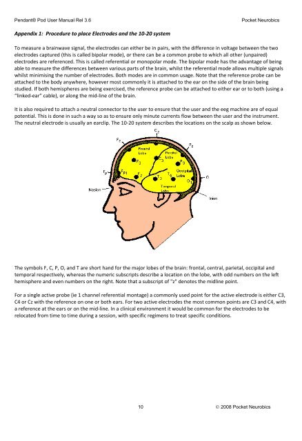
The neutral electrode is usually an earclip. The 10‐20 system describes the locations on the scalp as shown below.<br />
The symbols F, C, P, O, and T are short hand for the major lobes of the brain: frontal, central, parietal, occipital and<br />
temporal respectively, whereas the numeric subscripts describe a location on the lobe, with odd numbers on the left<br />
hemisphere and even numbers on the right. Note that a subscript of "z" denotes the midline point.<br />
For a single active probe (ie 1 channel referential montage) a commonly used point for the active electrode is either C3,<br />
C4 or Cz with the reference on one or both ears. For two active electrodes the most common points are C3 and C4, with<br />
a reference at the ears or on the mid‐line. In a clinical environment it would be common for the electrodes to be<br />
relocated from time to time during a session, with specific regimens to treat specific conditions.<br />
10 © 2008 Pocket Neurobics


