VISY-X - FAFNIR Gmbh
VISY-X - FAFNIR Gmbh
VISY-X - FAFNIR Gmbh

You also want an ePaper? Increase the reach of your titles
YUMPU automatically turns print PDFs into web optimized ePapers that Google loves.
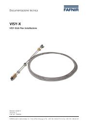
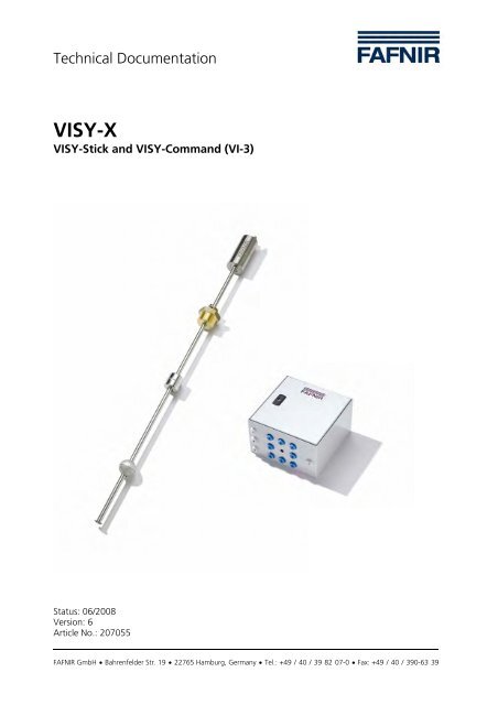
Technical Documentation<br />
<strong>VISY</strong>-X<br />
<strong>VISY</strong>-Stick and <strong>VISY</strong>-Command (VI-3)<br />
Status: 06/2008<br />
Version: 6<br />
Article No.: 207055<br />
<strong>FAFNIR</strong> GmbH • Bahrenfelder Str. 19 • 22765 Hamburg, Germany • Tel.: +49 / 40 / 39 82 07-0 • Fax: +49 / 40 / 390-63 39
List of Contents<br />
1 Introduction ...................................................................................3<br />
1.1 In this manual….................................................................................................4<br />
1.2 Contractor certification requirements .................................................................4<br />
1.3 Safety precautions..............................................................................................4<br />
2 Components of the <strong>VISY</strong>-X-System ..............................................6<br />
2.1 Wired version (standard).....................................................................................6<br />
2.2 Wireless version (radio system)............................................................................6<br />
3 Measuring value sensor <strong>VISY</strong>-Stick ..............................................7<br />
3.1 Design and operation .........................................................................................7<br />
3.2 Installation .........................................................................................................9<br />
3.3 Replacement instructions..................................................................................12<br />
3.4 <strong>VISY</strong>-Stick measuring value sensor dimensions..................................................13<br />
3.5 Electrical connection.........................................................................................18<br />
3.6 Specifying the installation offset .......................................................................19<br />
3.7 Technical data for <strong>VISY</strong>-Stick measuring value sensor........................................20<br />
3.8 Connection diagrams .......................................................................................21<br />
4 Measurement analysis system <strong>VISY</strong>-Command 8/16 ................24<br />
4.1 Design and operation .......................................................................................24<br />
4.2 VI-… interface card components ......................................................................25<br />
4.3 Installation .......................................................................................................27<br />
4.4 Auxiliary tank content measurement.................................................................28<br />
4.5 Fault diagnosis .................................................................................................31<br />
4.6 Replacement of components ............................................................................32<br />
4.7 Technical data for VP-… measuring transducer.................................................32<br />
5 Options .........................................................................................33<br />
5.1 Installation kit for LPG liquid gas.......................................................................33<br />
5.2 1" installation kit..............................................................................................34<br />
6 List of figures ...............................................................................35<br />
7 List of tables.................................................................................36<br />
8 APPENDIX .....................................................................................37<br />
8.1 EU Declaration of Conformity – <strong>VISY</strong>-Stick........................................................37<br />
8.2 EU Declaration of Conformity – VP-1, VP-2, VP-4..............................................38<br />
8.3 EU Declaration of Conformity – VI-3 .................................................................39<br />
8.4 EU type approval certificate – <strong>VISY</strong>-Stick ...........................................................40<br />
8.5 EU type approval certificate – VP-1 ...................................................................45<br />
© Copyright:<br />
Reproduction and translation only with the written consent of the <strong>FAFNIR</strong> company.<br />
<strong>FAFNIR</strong> reserves the right to carry out product alterations without prior notice.<br />
Page 2/48 <strong>VISY</strong>-Stick and <strong>VISY</strong>-Command
1 Introduction<br />
With the <strong>VISY</strong>-X system (volume information system), highly precise, continuous filling<br />
level measurements in up to 16 tanks are carried out directly at the filling station. The<br />
product temperature and the water level on the tank bottom are measured simultaneously.<br />
The system includes one or more <strong>VISY</strong>-Stick measuring value sensors, the <strong>VISY</strong>-Command<br />
measurement analysis system and the <strong>VISY</strong>-Setup configuration software.<br />
The robust <strong>VISY</strong>-Stick measuring value sensor can be installed without difficulty both by<br />
means of the screw-in unit with external threads as well as by using a riser installation.<br />
The freely adjustable height of the screw-in unit variant provides optimum adaptation to<br />
suit the onsite conditions. The probes can be used in ex-zone 0.<br />
The <strong>VISY</strong>-Stick measuring value sensors fitted in the tank are linked to the <strong>VISY</strong>-<br />
Command interface system installed in the filling station building.<br />
All parameters are set with a PC (notebook) at the <strong>VISY</strong>-Command measurement analyser.<br />
The parameters for the measuring value sensors and the tanks and, if needed, the<br />
measuring tables, are input or calculated using the easy to use <strong>VISY</strong>-Setup software. The<br />
temperature-compensated filling volume can also be calculated.<br />
<strong>VISY</strong>-Command gathers data from the measuring value sensors and transmits this on request<br />
to a higher-order system (e.g. POS).<br />
In most cases, the data transfer between the <strong>VISY</strong>-Stick measuring value sensors and the<br />
<strong>VISY</strong>-Command measurement analyser is made by cable. In this case, the power supply of<br />
the <strong>VISY</strong>-Stick measuring value sensor is ensured by the cable.<br />
In cases where there are no more free cable ducts available at the filling station, the radio<br />
system (wireless) can be used. In this case, power is supplied to the <strong>VISY</strong>-Stick measuring<br />
value sensors and the <strong>VISY</strong>-RFT transmitter by a battery. The installation of the radio system<br />
is a complex installation procedure and is described in detail in the “<strong>VISY</strong>-X wireless<br />
system” manual.<br />
• Technical documentation for <strong>VISY</strong>-X wireless system (German) – Art. No. 207115<br />
• Technical documentation for <strong>VISY</strong>-X wireless system (English) – Art. No. 207116<br />
If using the radio solution at the filling station, varying reception conditions must<br />
be anticipated as a result of the heavy passenger car and lorry traffic encountered<br />
there. This could, under certain circumstances, cause data reception in the <strong>VISY</strong>-<br />
Command to fail for some time. This would mean that the tank data are not updated<br />
at the set transmission intervals and that delivery data may, under certain<br />
circumstances, be lost.<br />
<strong>VISY</strong>-Stick and <strong>VISY</strong>-Command Page 3/48
1.1 In this manual…<br />
... you are guided through the installation and set-up of the <strong>VISY</strong>-Sticks and <strong>VISY</strong>-<br />
Command.<br />
These instructions contain a description of all steps needed to install the <strong>VISY</strong>-Sticks and<br />
the <strong>VISY</strong>-Command system.<br />
The <strong>VISY</strong>-Command system must be configured by using the <strong>VISY</strong>-Setup software after<br />
installation of the <strong>VISY</strong>-Sticks and the <strong>VISY</strong>-Command. Please follow the appropriate instructions<br />
in the <strong>VISY</strong>-Setup instructions.<br />
• Technical Documentation for <strong>VISY</strong>-Setup (German) – Art. No. 207112<br />
• Technical Documentation for <strong>VISY</strong>-Setup (English) – Art. No. 207113<br />
1.2 Contractor certification requirements<br />
The installation of the whole <strong>VISY</strong>-X system should only be performed by trained service<br />
engineers.<br />
1.3 Safety precautions<br />
The <strong>VISY</strong>-X system has been optimised for use at filling stations and may be employed for<br />
all conventional fuels. It is used for measuring and evaluating the filling levels in the filling<br />
station tanks. Please only use the system for this purpose. Observe and follow all product<br />
safety notes and operating instructions. The manufacturer accepts no liability for any<br />
form of damage resulting from improper use!<br />
The <strong>VISY</strong>-Stick measuring value sensor and the <strong>VISY</strong>-Command measurement analyser<br />
have been developed, manufactured and tested in accordance with state-of-the-art technology<br />
and with recognised safety rules and regulations. Nevertheless, hazards may arise<br />
from their use.<br />
The following precautions must be observed in order to reduce the risk of injury, the risk<br />
of electric shocks, fire or damage to the equipment:<br />
• Opening or removing the cover from the <strong>VISY</strong>-Command could result in a risk of<br />
electric shock.<br />
• Do not change or modify the system or add any equipment without the prior<br />
consent of the manufacturer.<br />
• Only use original spare parts. These comply with the technical requirements<br />
specified by the manufacturer.<br />
• The installation, operation and maintenance of the <strong>VISY</strong>-Stick measuring value<br />
sensor and the <strong>VISY</strong>-Command measurement analyser must only be carried out<br />
by expert, authorised personnel. The <strong>VISY</strong>-Command measurement analyser may<br />
only be installed and serviced by experienced electricians. Specialised knowledge<br />
must be obtained by undergoing regular training.<br />
Page 4/48 <strong>VISY</strong>-Stick and <strong>VISY</strong>-Command
• Operators, installers and service technicians must comply with all applicable<br />
safety regulations. This also applies to any local safety regulations and accident<br />
prevention regulations which are not stated in these operating instructions.<br />
• The <strong>VISY</strong>-Command measurement analyser is not suitable for outdoor installation<br />
and not for use in areas subject to explosion hazards. It is only intended for use<br />
within the <strong>VISY</strong>-X system.<br />
• The type VP-1 measuring transducer, and the type VI-... interface included in the<br />
<strong>VISY</strong>-Command measurement analyser must always be undamaged and clean.<br />
• During normal operation, the case cover of the <strong>VISY</strong>-Command measurement<br />
analyser system must be closed.<br />
• The product should only be powered with the permissible auxiliary power supply.<br />
The safety instructions in this manual are labelled as follows:<br />
If you do not observe these safety instructions, risk of an accident exists<br />
or the <strong>VISY</strong>-X system could be damaged.<br />
Useful information in these instructions that should be observed is printed in italics<br />
are marked with this symbol.<br />
<strong>VISY</strong>-Stick and <strong>VISY</strong>-Command Page 5/48
2 Components of the <strong>VISY</strong>-X-System<br />
There are two variants of the <strong>VISY</strong>-X system which differ in their data transmission technologies,<br />
the ...<br />
• ... wired version (standard)<br />
• ... wireless version (radio system)<br />
The different components of the two versions are covered in more detail in the points 2.1<br />
and 2.2.<br />
2.1 Wired version (standard)<br />
The wired version of the <strong>VISY</strong>-X system is the standard version. This version consists of<br />
the following components:<br />
• <strong>VISY</strong>-Stick measuring value sensor – this identical to that of the wireless version<br />
• <strong>VISY</strong>-Command 2/4/8/16 measurement analyser<br />
2.2 Wireless version (radio system)<br />
In cases in which there is no cable link from the <strong>VISY</strong>-Stick measuring value sensor to the<br />
<strong>VISY</strong>-Command measurement analyser, use can be made of the wireless version of the<br />
<strong>VISY</strong>-X system. In such cases, it is beneficial to install the wireless solution as this involves<br />
no excavation work. This version consists of the following components:<br />
• <strong>VISY</strong>-Stick measuring value sensor – this identical to that of the wired version<br />
• <strong>VISY</strong>-RFT transmitter<br />
• <strong>VISY</strong>-Command RF<br />
If using the radio solution at the filling station, varying reception conditions must<br />
be anticipated as a result of the heavy passenger car and lorry traffic encountered<br />
there. This could, under certain circumstances, cause data reception in the <strong>VISY</strong>-<br />
Command to fail for some time. This would mean that the tank data are not updated<br />
at the set transmission intervals and that delivery data may, under certain<br />
circumstances, be lost.<br />
Page 6/48 <strong>VISY</strong>-Stick and <strong>VISY</strong>-Command
3 Measuring value sensor <strong>VISY</strong>-Stick<br />
The <strong>VISY</strong>-Stick measuring value sensor is identical for the wired version and for the wireless<br />
version (radio solution).<br />
We provide the respective, appropriate version of the <strong>VISY</strong>-Stick for two possible installation<br />
methods (the riser installation and the installation in the manhole cover with screw-in<br />
unit):<br />
• <strong>VISY</strong>-Stick V M12 for a pipe installation (riser)<br />
• <strong>VISY</strong>-STICK M12 for installation in the manhole cover with a screw-in unit, brass<br />
R1½“ SW 55<br />
3.1 Design and operation<br />
The measuring value sensor consists of the housing (1) and a stainless steel probe tube (2)<br />
which is installed in the tank in height-adjustable form using the screw-in unit (3). A float<br />
(4) for measuring the product filling level and an additional float (5) for continuous water<br />
detection (Figure 1) move on this probe tube.<br />
The screw-in unit (3) is not required for the measuring value sensor for riser installation.<br />
A height adjustment is not needed with the pipe installation as the measuring<br />
value sensor is on the tank bottom and can move freely within the pipe.<br />
The water float must be removed for products with a density greater than<br />
0.9kg/l!<br />
<strong>VISY</strong>-Stick and <strong>VISY</strong>-Command Page 7/48
Figure 1: Mode of operation of the magnetostrictive measuring principle<br />
1 – Case 5 – Water float 9 – Permanent magnet<br />
2 – Probe tube 6 – Magnetostrictive wire 10 – Torsion pulse<br />
3 – Screw-in unit 7 – Sensor electronics<br />
4 – Product float 8 - Circular magnetic field<br />
The measuring value sensor operates according to the magnetostrictive measuring principle.<br />
The probe tube contains a wire (6) made of magnetostrictive material. The sensor<br />
electronics transmit pulses through the wire that generate a circular magnetic field (8).<br />
Permanent magnets (9) are used as filling level sensors and are installed in both the product<br />
float and the water float. The magnetic fields of the float magnets axially magnetise<br />
the wire in this area. Due to the overlapping of the two magnetic fields, a torsion pulse<br />
(10), which runs in both directions through the wire from the float position, is created in<br />
the area of the float magnets. One torsion pulse runs directly to the probe head and the<br />
other one is reflected at the bottom end of the probe tube. The time between the current<br />
pulse being transmitted and the two torsion pulses arriving at the probe head is measured<br />
and the float position calculated. The position of the water float is calculated by<br />
measuring a second pulse.<br />
Page 8/48 <strong>VISY</strong>-Stick and <strong>VISY</strong>-Command
3.2 Installation<br />
When installing and servicing the <strong>VISY</strong>-Stick measuring value sensor, the<br />
requirements of the expo and BetrSichV regulations and of equipment<br />
safety law must be observed, as must the generally accepted technical<br />
regulations and these operating instructions.<br />
Also observe any local safety regulations and accident prevention regulations<br />
which are not stated in these operating instructions.<br />
The <strong>VISY</strong>-Stick measuring value sensors must only be connected to measuring transducers<br />
that have been certified by a recognised European testing authority and the electrical<br />
data of which meet the following requirements:<br />
• U i 15 V<br />
• I i 60 mA<br />
• P i 0.1 W<br />
You can connect several <strong>VISY</strong>-Stick measuring value sensors to the <strong>VISY</strong>-Command<br />
measurement analyser. First of all, however, install the <strong>VISY</strong>-Stick measuring value sensors<br />
in the tanks by positioning the sensors as centrally as possible in the middle of the tank.<br />
Height differences between the deepest point of the tank bottom and the end of the<br />
probe tube (= installation offset) must be input later in the <strong>VISY</strong>-Setup configuration program.<br />
Figure 2 shows the height difference for various tank diameters of cylindrical tanks according<br />
to DIN 6608, 6616, 6617 and 6624 if the installation is carried out deviating from<br />
the longitudinal axis and the probe has direct contact with the tank bottom.<br />
The value to be input for the installation offset consists of the height difference b<br />
from Figure 2 and the displacement of the probe tube toward the top.<br />
During installation, make a note of which measuring value sensor is connected to<br />
which port on the VP board. Also write down the corresponding tank and product<br />
in which the each measuring value sensor is installed. You will need these<br />
data later for the configuration with <strong>VISY</strong>-Setup.<br />
<strong>VISY</strong>-Stick and <strong>VISY</strong>-Command Page 9/48
Height difference for cylindrical tanks according to DIN 6608, 6616, 6624 deviating<br />
from the longitudinal axis.<br />
b: Height difference tank bottom – bottom end of probe tube [mm]<br />
Tank diameter:<br />
a: Deviation from longitudinal axis [mm]<br />
Figure 2: Installation offset for measuring value sensors<br />
Page 10/48 <strong>VISY</strong>-Stick and <strong>VISY</strong>-Command
3.2.1 Tank pipe coupling ≥ 1½ inch (2" for <strong>VISY</strong>-Stick Advanced)<br />
During assembly, it is important to make sure that the probe tube is not<br />
bent.<br />
If the tank pipe coupling provided for assembly has an internal thread of at least 1½<br />
inches, the installation of the probe (see Figure 4) must be carried out in the following<br />
steps. For internal threads that are larger than 1½ inches, the corresponding reduction<br />
pieces must be used:<br />
• Check that the circlip on the end of the probe is securely located so that the float<br />
is unable to fall off into the tank.<br />
The floats must be pushed onto the probe tube with the marking "TOP" facing<br />
upward so that the measurement can be carried out.<br />
• Use a hexagon socket key (5 mm) to loosen the stuffing box (SW 30, SW = spanner<br />
width) and the locking screw so that the screw-in unit can be moved easily<br />
on the probe tube.<br />
• Provide the screw-in unit with suitable sealing material and then screw it into the<br />
tank thread together with the measuring value sensor.<br />
• Finish assembly by gently pressing the probe tube onto the tank bottom and then<br />
pulling it up 5 … 10 mm.<br />
• Connect earthing and equipotential bonding cables with the exterior earth terminal<br />
A 1" installation kit is also available as an option. This optional installation kit<br />
consists of product and water floats and a screw-in unit. It makes possible the installation<br />
of a <strong>VISY</strong>-Stick using an R1 threaded sleeve.<br />
3.2.2 Pipe installation (riser)<br />
During the assembly work, it is important to make sure that the probe<br />
tube is not bent.<br />
The usual pipe installation is made with 3" or 4" pipes. Installation of the <strong>VISY</strong>-Stick V<br />
M12 probe (see Figure 4) is made in the following steps:<br />
• Check that the circlip on the end of the probe is securely located so that the float<br />
is unable to fall off into the tank.<br />
The floats must be pushed onto the probe tube with the marking "TOP" facing<br />
upward so that the measurement can be carried out.<br />
<strong>VISY</strong>-Stick and <strong>VISY</strong>-Command Page 11/48
• Pull the riser installation kit (article no.: 900074) for centering the head of the<br />
probe of the <strong>VISY</strong>-Stick in the installation tube over the probe head and adapt to<br />
a 3" pipe if required.<br />
• Connect and secure the supplied <strong>VISY</strong>-Stick connection cable to the <strong>VISY</strong>-Stick.<br />
• Let the <strong>VISY</strong>-Stick measuring value sensor slowly slide into the riser and place<br />
carefully on the bottom of the tank.<br />
• Install a suitable cable grommet in the sealing cap of the pipe (riser) and guide<br />
the supplied connection cable through this.<br />
Figure 3: <strong>VISY</strong>-Stick V M12 installed in pipe and <strong>VISY</strong>-Stick M12 with screw-in unit<br />
3.3 Replacement instructions<br />
Sealing cap with cable gland<br />
Connection cable<br />
Screw-in coupling<br />
Pipe installation kit<br />
After replacing the <strong>VISY</strong>-Stick measuring value sensor, the following values must be entered<br />
again using <strong>VISY</strong>-Setup:<br />
• The device number of the new <strong>VISY</strong>-Stick measuring value sensor<br />
• Check the installation offset value and correct as necessary<br />
Page 12/48 <strong>VISY</strong>-Stick and <strong>VISY</strong>-Command
3.4 <strong>VISY</strong>-Stick measuring value sensor dimensions<br />
The measuring value sensors are distinguished according to the installation method (pipe<br />
installation or installation in the manhole cover) and according to the version (Basic/Standard<br />
or Advanced).<br />
3.4.1 Basic/Standard measuring value sensors<br />
Probe length<br />
M12 connector<br />
1. brown +<br />
2. white A<br />
3. blue -<br />
4. black B<br />
Earth connector<br />
Sensor head<br />
Stuffing box<br />
Locking screw<br />
Screw-in unit MS<br />
R1 1/2 SW 55<br />
Probe tube Ø 12<br />
Product float<br />
Ø 43x43<br />
Water float<br />
Ø 43<br />
Removable circlip<br />
Figure 4: <strong>VISY</strong>-Stick M12 advanced for installation in the manhole cover<br />
Dimensions in mm<br />
<strong>VISY</strong>-Stick and <strong>VISY</strong>-Command Page 13/48
Probe length<br />
M12 connector<br />
1. brown +<br />
2. white A<br />
3. blue -<br />
4. black B<br />
Earth connector<br />
Figure 5: <strong>VISY</strong>-Stick V M12 advanced for pipe installation<br />
Pipe installation kit<br />
Marking applied by laser<br />
Sensor head<br />
Probe tube Ø Ø 12 12<br />
Product float<br />
Ø 43x43<br />
Water float<br />
Ø 43<br />
Removable circlip<br />
Dimensions in mm<br />
Page 14/48 <strong>VISY</strong>-Stick and <strong>VISY</strong>-Command
3.4.2 Advanced measuring value sensors<br />
Probe length<br />
M12 connector<br />
1. brown +<br />
2. white A<br />
3. blue -<br />
4. black B<br />
Earth connector<br />
Marking applied by laser<br />
Sensor head<br />
Stuffing box<br />
Locking screw<br />
Screw-in unit MS<br />
R1 1/2 SW 55<br />
Probe tube Ø 12<br />
Product float<br />
Ø 43x43<br />
Water float<br />
Ø 43<br />
Removable circlip<br />
Figure 6: <strong>VISY</strong>-Stick M12 Advanced for installation in manhole cover<br />
Dimensions in mm<br />
<strong>VISY</strong>-Stick and <strong>VISY</strong>-Command Page 15/48
Probe length<br />
Figure 7: <strong>VISY</strong>-Stick V M12 Advanced for pipe installation<br />
M12 connector<br />
1. brown +<br />
2. white A<br />
3. blue -<br />
4. black B<br />
Earth connector<br />
Pipe installation kit<br />
Marking applied by laser<br />
Sensor head<br />
Probe tube Ø 12 Ø 12<br />
Product float<br />
Ø 54<br />
Water float<br />
Ø 43<br />
Removable circlip<br />
Dimensions in mm<br />
Page 16/48 <strong>VISY</strong>-Stick and <strong>VISY</strong>-Command
3.4.3 Measuring value sensor for AdBlue<br />
Probe length<br />
M12 connector<br />
1. brown +<br />
2. white A<br />
3. blue -<br />
4. black B<br />
Earth connector<br />
Sensor head<br />
Screw-in unit G3/8<br />
(cutting ring coupling)<br />
Reducer R 1 1/2,<br />
stainless steel<br />
Probe tube Ø 12<br />
Product float<br />
Ø 43x43<br />
Removable circlip<br />
Dimensions in mm<br />
Figure 8: <strong>VISY</strong>-Stick N M12 for AdBlue with screw-in unit for installation in manhole cover<br />
<strong>VISY</strong>-Stick and <strong>VISY</strong>-Command Page 17/48
3.5 Electrical connection<br />
Proceed as follows for wiring each <strong>VISY</strong>-Stick measuring value sensor to the <strong>VISY</strong>-<br />
Command measurement analyser.<br />
Supplied connection cable: Connect M12 coupling to M12 connector on the probe head.<br />
Connect the other end of the cable to the cable laid in the dome shaft (coming from<br />
<strong>VISY</strong>-Command) e.g. using an installation sleeve.<br />
Note the M12 socket connection labelling of the supplied connection cable in order to<br />
connect the connecting cable correctly to the <strong>VISY</strong>-Command measurement analyser:<br />
• brown+ socket 1<br />
• white A socket 2<br />
• blue - socket 3<br />
• black B socket 4<br />
Figure 9: Connection assignment of socket<br />
The connection cable between measuring value sensor and measurement analyser has<br />
the following specification:<br />
• Four-core unshielded cable<br />
• Oil-resistant<br />
• Refer to the following table for the required wire cross section:<br />
Cable length Wire cross section<br />
up to 100 m 4 x 0.5 mm²<br />
up to 200 m 4 x 1.0 mm²<br />
Table 1: Cable length and wire cross section<br />
• The connecting cable to the measurement analyser must be blue or labelled in<br />
blue as it is a cable for intrinsically safe electric circuits. The cable is allowed to<br />
have a diameter between 6 - 10 mm so that it can still be safely sealed by the cable<br />
gland in the <strong>VISY</strong>-Command unit.<br />
The earth connector in the probe head can be used for earthing or equipotential bonding.<br />
The earthing or equipotential bonding must be carried out by the installer in accordance<br />
with the national installation regulations applicable in each case.<br />
Please comply with general installation regulations concerning equipotential<br />
bonding<br />
Page 18/48 <strong>VISY</strong>-Stick and <strong>VISY</strong>-Command
3.6 Specifying the installation offset<br />
3.6.1 <strong>VISY</strong>-Stick with screw-in unit<br />
At the end of the assembly, the probe tube is pressed lightly onto the tank bottom and<br />
then pulled up about 10 mm (see also Point 3.2.1). This position must be maintained by<br />
tightening down the stuffing box and the locking screw.<br />
If you do not pull up the probe tube slightly again, it could be bent when<br />
the stuffing box is tightened down.<br />
During later configuration of the individual measuring points with the <strong>VISY</strong>-Setup program,<br />
the installation offset and device number of each probe is required. This data<br />
should now be written down together with the tank number and the product.<br />
The installation offset consists of the distance of the end of the probe from the<br />
tank bottom plus the value determined from the table (Figure 2 on page ).<br />
3.6.2 <strong>VISY</strong>-Stick without screw-in unit (pipe installation)<br />
A possible installation offset results exclusively from the installation position if this could<br />
not be carried out in the longitudinal axis of the tank (see also the table in Figure 2 on<br />
page 10).<br />
During later configuration of the individual measuring points with the <strong>VISY</strong>-Setup program,<br />
the installation offset and device number of each probe is required. This data<br />
should now be written down together with the tank number and the product.<br />
3.6.3 <strong>VISY</strong>-Stick N M12 (for AdBlue) with cutting ring coupling<br />
as per point 3.6.1<br />
<strong>VISY</strong>-Stick and <strong>VISY</strong>-Command Page 19/48
3.7 Technical data for <strong>VISY</strong>-Stick measuring value sensor<br />
Explosion protection EEx ia IIC T6<br />
Approval TÜV 99 ATEX 1496<br />
Protection class IP 68<br />
Permissible ambient temperature<br />
(probe head)<br />
-25 °C to 75 °C in T4<br />
-25 °C to 65 °C in T5<br />
-25 °C to 50 °C in T6<br />
Connection data U i 15 V<br />
P i 0.1 W<br />
I i 60 mA<br />
C i 10 nF<br />
L i 0.1 mH<br />
Probe length 2000 mm (tank diameter 1600 mm)<br />
2400 mm (tank diameter 2000 mm)<br />
2900 mm (tank diameter 2500 mm)<br />
3300 mm (tank diameter 2900 mm)<br />
Probe head Basic / Standard: Ø 50 mm x 107 mm<br />
Advanced:<br />
Product float Basic / Standard: cylinder Ø 43 mm, height 40 mm<br />
Advanced: cylinder Ø 54 mm, height 33 mm<br />
Water float Ball Ø 43 mm<br />
Connection Screw-in unit with the option of<br />
freely variable height adjustment (standard R 1½)<br />
Measurement accuracy: Product Basic: ± 2 mm<br />
Standard: better than ± 0.5 mm<br />
Advanced: ± 0.1 mm<br />
Measurement accuracy: temperature<br />
Basic: ± 1 °C<br />
Standard: better than ± 0.3 °C<br />
Advanced: better than ± 0.3 °C<br />
Water detection continuous from 30 mm<br />
Table 2: Technical data for <strong>VISY</strong>-Stick measuring value sensor<br />
Page 20/48 <strong>VISY</strong>-Stick and <strong>VISY</strong>-Command
3.8 Connection diagrams<br />
Figure 10: Connection diagram for max. 8 measuring value sensors<br />
<strong>VISY</strong>-Stick and <strong>VISY</strong>-Command Page 21/48
Figure 11: Connection diagram for max. 16 measuring value sensors<br />
Page 22/48 <strong>VISY</strong>-Stick and <strong>VISY</strong>-Command
Figure 12: Connection diagram for <strong>VISY</strong>-Command RF for max. 16 measuring value sensors<br />
<strong>VISY</strong>-Stick and <strong>VISY</strong>-Command Page 23/48
4 Measurement analysis system <strong>VISY</strong>-Command 8/16<br />
The <strong>VISY</strong>-Command units for the <strong>VISY</strong>-X system in the wired version (standard) and the<br />
wireless version (radio solution) are different and have the following designations:<br />
• <strong>VISY</strong>-Command 2/4/8/16 - for the wired version (standard)<br />
• <strong>VISY</strong>-Command RF - for the wireless version (radio system)<br />
4.1 Design and operation<br />
4.1.1 <strong>VISY</strong>-Command 2/4/8/16 - wired version (standard)<br />
The <strong>VISY</strong>-Command 2/4/8/16 measurement analyser is available for connecting up a<br />
maximum number of 2/4/8 or 16 <strong>VISY</strong>-Stick measuring value sensors. It comprises a VI-…<br />
interface card and one or two VP-… measuring transducers fitted in an IP 55 control unit.<br />
The measurement analyser electrifies the measuring value sensor. The measurement analyser<br />
receives the measured values from the measuring value sensors, stores these data<br />
temporarily and makes the data available to a higher level system (e.g. central computer).<br />
Communication runs via a serial interface, either the RS232 or RS485 (2-wire). There are<br />
various reports available for the usual filling station computers.<br />
The EPSI and IFSF/LON interfaces and ethernet are also optionally available.<br />
• IFSF-LON interface converter operating instructions in German, Art.-No. 207090<br />
• IFSF-LON interface converter operating instructions in English, Art.-No. 207092<br />
• EPSI interface converter operating instructions in German, Art.-No. 207117<br />
• EPSI interface converter operating instructions in English, Art.-No. 207118<br />
4.1.2 <strong>VISY</strong>-Command RF - wireless version (radio solution)<br />
The <strong>VISY</strong>-Command RF measurement analyser is able to process data from up to 16 <strong>VISY</strong>-<br />
Stick measuring value sensors. It comprises a VI-… interface card and an RF receiver<br />
board fitted in an IP 55 control unit.<br />
Each measuring value sensor is supplied with electric power via a <strong>VISY</strong>-RF transmitter<br />
module (connected directly to the <strong>VISY</strong>-Stick measuring value sensor). The <strong>VISY</strong>-RF transmitter<br />
module reads the data from the <strong>VISY</strong>-Stick and sends these to the <strong>VISY</strong>-Command<br />
RF measurement analyser. The data received from the <strong>VISY</strong>-Command RF are evaluated,<br />
stored temporarily and made available to a higher level system (e.g. central computer).<br />
Communication runs via a serial interface, either the RS232 or RS485 (2-wire). There are<br />
various reports available for the usual filling station computers.<br />
The EPSI and IFSF/LON interfaces and ethernet are also optionally available. See also point<br />
4.1.1 for the operating instructions.<br />
Page 24/48 <strong>VISY</strong>-Stick and <strong>VISY</strong>-Command
If using the radio solution at the filling station, varying reception conditions must<br />
be anticipated as a result of the heavy passenger car and lorry traffic encountered<br />
there. This could, under certain circumstances, cause data reception in the <strong>VISY</strong>-<br />
Command to fail for some time. This would mean that the tank data are not updated<br />
at the set transmission intervals and that delivery data may, under certain<br />
circumstances, be lost.<br />
4.2 VI-… interface card components<br />
(see Figure 11 and Figure 10)<br />
4.2.1 Status display<br />
After switching on or resetting the VI-… interface card, the software version of the interface<br />
card is initially shown. This is represented by three numbers which appear one after<br />
the other on the display, e.g. 3 – 1 – 5 corresponds to Version 3.15.<br />
Afterwards, the status of the measuring value sensors 1 to 16 is automatically displayed.<br />
First the number (1 to 16) of the measuring value sensor, followed by the equal sign (=)<br />
and finally the status (0 to 99; see the connection diagram or the <strong>VISY</strong>-Setup documentation<br />
for the meaning). After a short pause, the status of the next measuring value sensor<br />
is shown.<br />
4.2.2 Service socket<br />
The 9-pin D-Sub socket on the serial RS232 interface is used for connecting, e.g <strong>VISY</strong>-<br />
Setup, <strong>VISY</strong>-Quick, auxiliary tank content measurement, etc.<br />
4.2.3 DIP switch S1<br />
Service mode<br />
Activation of the serial RS232 service interface for system configuration using the <strong>VISY</strong>-<br />
Setup program. The DIP switches S11 and S12 must be in the "OFF" position.<br />
<strong>VISY</strong>-Quick protocol<br />
To activate the serial RS232 service interface and to link up with the <strong>VISY</strong>-Quick protocol<br />
(<strong>FAFNIR</strong> protocol): DIP switch S11 must be in the "OFF" position and S12 must be in the<br />
"ON" position.<br />
Auxiliary tank content measurement<br />
To activate the serial RS232 service interface for connecting up an auxiliary tank content<br />
measurement: DIP switch S11 must be in the "ON" position and S12 must be in the<br />
"OFF" position.<br />
<strong>VISY</strong>-Stick and <strong>VISY</strong>-Command Page 25/48
4.2.4 Host<br />
The serial host interface (galvanically isolated) for communication with a higher level system,<br />
e.g. filling station computer or PC, is configured as an RS232 and as an RS485 interface<br />
(2-wire). Depending on requirements, the host can be connected to the RS232 interface<br />
or to the RS485 interface. The data protocol used by the interface is selected with<br />
the <strong>VISY</strong>-Setup software using the input of the host code. The VI-… interface card automatically<br />
recognises the interface to which the host is connected.<br />
Simultaneous operation of the RS232 interface and the RS485 interface is<br />
not possible.<br />
If the RS485 interface is being used, it is advisable for reasons of interference resistance<br />
to use a 3-core cable and in addition to the ports A+ and B- also to connect the interface<br />
earth (┴ - terminal on host interface) of the <strong>VISY</strong>-Command to the interface earth on the<br />
host system (if provided there as connection terminal).<br />
4.2.5 LED - RxD Host<br />
This light-emitting diode (LED) indicates incoming data from the host computer.<br />
4.2.6 LED - TxD Host<br />
This light-emitting diode (LED) indicates data going to the host computer.<br />
4.2.7 Expansion - RS485 interface<br />
Serial RS485 port (galvanically isolated) using which the data can be transmitted to other<br />
system components (e.g. <strong>VISY</strong>-View if the host interface is busy). This interface is unidirectional.<br />
This means that data are only sent from the <strong>VISY</strong>-Command to the system<br />
components connected there. The system components receive the data without having to<br />
send a request. This means that in contrast to bidirectional interfaces, it is possible to<br />
connect several system components (e.g. several <strong>VISY</strong>-Views) to the expansion interface<br />
in parallel. Theoretically, up to 31 system components can be connected to this interface.<br />
This interface is deactivated at the factory. It can be activated with the <strong>VISY</strong>-Setup program.<br />
Please refer to the technical documentation supplied with the device being connected<br />
to determine whether other settings are required. If a shielded cable is used, the<br />
cable shield must be placed on the reference earth of the interfaces ( ┴ - connection terminal).<br />
4.2.8 LED – TxD expansion<br />
This light-emitting diode (LED) indicates that data is being transmitted via the extension<br />
interface.<br />
Page 26/48 <strong>VISY</strong>-Stick and <strong>VISY</strong>-Command
4.2.9 Reset<br />
This button can be used to effect a reset of the VI-… interface card.<br />
4.3 Installation<br />
The <strong>VISY</strong>-Command measurement analyser must be securely fixed to a wall inside the<br />
filling station building. The supply of auxiliary power (electrical connection) requires a<br />
permanent installation (no plug assembly) and is made via the bottom right cable entry<br />
(grey). Connect the supply voltage to the terminal blocks provided. The VP-… measuring<br />
transducer and the VI-… interface card are already wired at the factory.<br />
The <strong>VISY</strong>-Command measurement analyser is not suitable for outdoor<br />
installation.<br />
When installing/operating the <strong>VISY</strong>-Command measuring analyser, the<br />
requirements of the ExVo and BetrSichV regulations and of equipment<br />
safety law must be observed, as must the generally accepted technical<br />
regulations and these operating instructions.<br />
4.3.1 <strong>VISY</strong>-Command - wired version (standard)<br />
Connect up the <strong>VISY</strong>-Stick measuring value sensor in the door of the control unit according<br />
to the connection diagram (see Figure 10 and Figure 11). For this, use the blue cable<br />
entries, which are provided for the intrinsically safe electric circuits for the measuring<br />
value sensors.<br />
The maximum external inductance including the cable must not exceed 40 mH and the<br />
maximum capacitance must not exceed 680 nF (see data sheet of the cable used).<br />
Connect the "Host" terminal with the host computer as shown in the connection diagram.<br />
After connecting the <strong>VISY</strong>-Stick measuring analysis sensors, you can start configuration<br />
(see operating instructions for the <strong>VISY</strong>-Setup configuration program).<br />
4.3.2 <strong>VISY</strong>-Command RF - wireless version (radio solution)<br />
The installation of the radio system is a complex installation procedure and is described in<br />
detail in the <strong>VISY</strong>-X wireless system manual:<br />
• <strong>VISY</strong>-X wireless system operating instructions in German – Art. No. 207115.<br />
• <strong>VISY</strong>-X wireless system operating instructions in English – Art. No. 207116.<br />
<strong>VISY</strong>-Stick and <strong>VISY</strong>-Command Page 27/48
4.4 Auxiliary tank content measurement<br />
The <strong>VISY</strong>-X system is able to communicate a lower-order auxiliary tank content measurement<br />
to call up filling level and temperature data. The benefit of this function is its ability<br />
to continue using older, previously installed tank content measurement systems for which<br />
spare parts are no longer available. Normally, a failure of one of the individual measuring<br />
value sensors would mean that the complete system would have to be replaced, including<br />
all measuring value sensors that are still working. The function of the auxiliary tank content<br />
measurement allows old tank content measurement components that are still working<br />
to remain in use. Only defective measuring value sensors have to replaced with a<br />
<strong>VISY</strong>-Stick connected to a <strong>VISY</strong>-Command system. Old measuring value sensors that are<br />
still working remain with the existing measurement analysis system. This then no longer<br />
supplies data directly to the filling station control system and to the cashier system, but<br />
rather to the <strong>VISY</strong>-Command.<br />
Old measuring<br />
value<br />
sensor<br />
Tank 1<br />
OK<br />
Old measurement<br />
analysis<br />
Tank 2<br />
DEFECTI<br />
RS232 RS232<br />
Tank 3<br />
OK<br />
Figure 13: Tank content measurement with defective measuring value sensor in tank 2<br />
Tank 1<br />
OK<br />
<strong>FAFNIR</strong><br />
<strong>VISY</strong>-<br />
Old measurement<br />
analysis<br />
system<br />
Tank 2<br />
OK<br />
Data for tanks 1 and 3:<br />
exclusively product filling<br />
Data for tanks 1 to 3: All<br />
level, water filling level,<br />
available measured and<br />
temperature<br />
alarm data<br />
RS232<br />
Service<br />
<strong>FAFNIR</strong><br />
<strong>VISY</strong>-<br />
RS232<br />
Command Host inter-<br />
interface<br />
face<br />
Tank 3<br />
OK<br />
Filling station<br />
control<br />
system,<br />
cashier<br />
Filling station<br />
control system,<br />
cashier<br />
system, mo-<br />
Figure 14: Tank content measurement with <strong>VISY</strong>-Command, <strong>VISY</strong>-Stick and an old measurement<br />
analysis system<br />
Page 28/48 <strong>VISY</strong>-Stick and <strong>VISY</strong>-Command
4.4.1 Necessary conditions<br />
The following fundamental conditions must be fulfilled to install and operate an auxiliary<br />
tank content measurement system such as the one described in Figure 14 with a <strong>VISY</strong>-<br />
Command system.<br />
• For an installed tank content measurement system to be operated as an auxiliary<br />
tank content measurement at the <strong>VISY</strong>-Command, it must be equipped for data<br />
communication via an RS232 interface that can work in 3-wire mode (RxD, TxD,<br />
GND) without control wires (hardware handshake).<br />
• For an installed tank content measurement system to be operated as an auxiliary<br />
tank content measurement at the <strong>VISY</strong>-Command, it must support one of the serial<br />
data protocols that are commonly used in the field of filling stations.<br />
• The serial interface parameters and data protocol used between the tank content<br />
measurement system installed and the cashier system / filling station control system<br />
must be known and supported by the <strong>VISY</strong>-X system. If this is not known,<br />
the interface parameters and the data protocol can be identified with the aid of<br />
the "<strong>FAFNIR</strong> Serial Monitor" program. This requires technical experience in using<br />
serial interfaces and knowledge of the ASCII character set, in particular regarding<br />
the control characters.<br />
• The auxiliary tank content measurement system is connected to the service interface<br />
of the <strong>VISY</strong>-Command measurement analyser, ruling out any other special<br />
function for the service interface, e.g. for connecting up a modem or ethernet<br />
converter. (modem or ethernet converter can only be connected to the host interface.)<br />
• The VI-... interface card in the <strong>VISY</strong>-Command system must be equipped with<br />
firmware version V 3.15 or a later version for it to work with an auxiliary tank<br />
content measurement system. Version older than V 3.15 must be updated to the<br />
current firmware version.<br />
• The program <strong>VISY</strong>-Setup Version 3.2 or later is needed for configuring an auxiliary<br />
tank content measurement system in <strong>VISY</strong>-Command.<br />
• If measuring tables and/or alarm settings are stored in the auxiliary tank content<br />
measurement system, it must be possible to read these out or off so that they<br />
can be transmitted to <strong>VISY</strong>-Command via <strong>VISY</strong>-Setup.<br />
<strong>VISY</strong>-Stick and <strong>VISY</strong>-Command Page 29/48
4.4.2 Installation<br />
The following additional documentation must be noted during installation:<br />
• <strong>VISY</strong>-Setup technical documentation<br />
• <strong>FAFNIR</strong> Serial Monitor<br />
• Technical documentation for old tank content measurement system<br />
• Technical documentation for filling station control system or cashier system<br />
(1) Install <strong>VISY</strong>-Stick and <strong>VISY</strong>-Command as described in Chapter 3.2 Installation.<br />
(2) Configure the <strong>VISY</strong>-Command measurement analyser with the <strong>VISY</strong>-Setup configuration<br />
software.<br />
If measuring tables and/or alarm thresholds are configured in the auxiliary tank<br />
content measurement system, the same settings must be made for <strong>VISY</strong>-<br />
Command with <strong>VISY</strong>-Setup.<br />
(3) Separate the RS232 connection between the filling station control system or<br />
cashier system and the old tank content measurement system.<br />
(4) Set up a new RS232 connection between the old tank content measurement system<br />
and the service interface (9-pin D-Sub socket on the VI-… card) of <strong>VISY</strong>-<br />
Command with a 3-core cable. <strong>FAFNIR</strong> is able to supply the D-Sub 9M adapter as<br />
an accessory. This is equipped with terminals, eliminating the need to solder a D-<br />
Sub connector. A cable length of 12 metres should not be exceeded. Screening<br />
of <strong>VISY</strong>-Command is not necessary. If the auxiliary tank content measurement<br />
system requires a screened cable, the screening should be located in <strong>VISY</strong>-<br />
Command on an earth point or directly on the housing earth.<br />
Auxiliary tank content<br />
measurement<br />
RS232 interface<br />
GND TxD RxD<br />
<strong>FAFNIR</strong> <strong>VISY</strong>-Command<br />
VI-… interface card<br />
TxD<br />
RxD S1<br />
GND<br />
Service interface<br />
DIP switch S1:mode<br />
OFF OFF - <strong>VISY</strong>-Setup<br />
OFF ON - <strong>VISY</strong>-Quick<br />
ON OFF - Auxiliary tank content<br />
measurement<br />
ON ON - not used<br />
Connection Sub-D-9: assignment<br />
Pin 2: TxD<br />
Pin 3: RxD<br />
Pin 5: GND<br />
Figure 15: Connecting auxiliary tank content measurement system to <strong>VISY</strong>-Command<br />
Page 30/48 <strong>VISY</strong>-Stick and <strong>VISY</strong>-Command
(5) Set the DIP switches on the VI-… interface card to the ON OFF position (see<br />
Figure 15). The interface card now starts data interrogation of the auxiliary tank<br />
content measurement system. If everything is correctly wired and configured, the<br />
data for all tanks should now be available in the filling station control system or<br />
cashier system. Delays could arise if the cashier system or filling station control<br />
system only occasionally interrogates the tank content measurement system data.<br />
(6) If you want to check whether data from the auxiliary tank content measurement<br />
system has been correctly read by <strong>VISY</strong>-Command, set the DIP switches back to<br />
the OFF OFF position (service interface mode = <strong>VISY</strong>-Setup) and connect <strong>VISY</strong>-<br />
Setup to the service interface again. When doing this, make sure that the DIP<br />
switches are in the OFF OFF position before you disconnect the cable to the auxiliary<br />
tank content measurement system. By observing this sequence, the data read<br />
from the auxiliary tank content measurement system remain in <strong>VISY</strong>-Command<br />
for as long as it has been defined in <strong>VISY</strong>-Setup, configuration item "Timeout...".<br />
If you were to disconnect the cable first, <strong>VISY</strong>-Command would continue trying<br />
to interrogate and then delete the data as it would no longer receive a reply<br />
(status code: 11).<br />
4.5 Fault diagnosis<br />
As soon as configuration has been completed with <strong>VISY</strong>-Setup, you can monitor the operation<br />
of the measuring value sensors using the status display on the VI interface. The<br />
display shows, one after the other, the number of a measuring value sensors (e.g. 5 =<br />
measuring value sensor on connection 5), an equal sign and the corresponding status<br />
(e.g. 0 = in operation). Accordingly, one measuring value sensor after another is interrogated<br />
in a continuous loop operation. The meanings of the status reports are explained in<br />
the door of the control unit (see Table 3)<br />
Status code Status of the measuring value sensor<br />
0 in operation<br />
1 not ready for operation<br />
5 temperature measurement not possible<br />
6 filling level measurement not possible<br />
7 reduced measuring accuracy<br />
8 1) data transmission interference between <strong>VISY</strong>-Stick and <strong>VISY</strong>-<br />
RFT<br />
9 1) no data transmission between <strong>VISY</strong>-Stick and <strong>VISY</strong>-RFT<br />
10 data transmission interference<br />
11 no data transmission<br />
13 1) waiting for first radio data transmission<br />
99 not configured<br />
after Reset firmware version of the VI interface<br />
1)<br />
Only in the wireless version<br />
Table 3: Error codes table<br />
<strong>VISY</strong>-Stick and <strong>VISY</strong>-Command Page 31/48
4.6 Replacement of components<br />
Only the VI-… interface card or VP-… measuring transducer can be replaced. These must<br />
be replaced as complete assembly groups. The printed circuit boards are mounted on a<br />
support rail from which they can be easily detached with a screwdriver.<br />
4.7 Technical data for VP-… measuring transducer<br />
Explosion protection [EEx ia] IIC<br />
EC type approval certificate TÜV 98 ATEX 1380<br />
Permissible ambient<br />
temperatures:<br />
-20 °C to +40 °C<br />
Supply circuit a<br />
(terminals L, N, PE)<br />
Sensor circuits<br />
(terminals + A B -)<br />
Measurement and control<br />
circuits<br />
(plug connector S1)<br />
Table 4: Technical data for VP-… measuring transducer<br />
Alternating voltage 230 V ±10 %; approx. 2 VA<br />
Maximum voltage for safety reasons Um = 253 V<br />
in ignition protection class intrinsic safety EEx ia IIC<br />
(linear output characteristic)<br />
Maximum values U0 = 14.3 V<br />
I0 = 28 mA<br />
P0 = 98 mW<br />
Maximum permitted external inductance 40 mH<br />
Maximum permitted external capacitance 680 nF<br />
Interface electric circuit U N = 5 V<br />
Maximum voltage for safety reasons U m = 100 V<br />
The intrinsically safe sensor electric circuits are safely galvanically separated from the supply<br />
circuit (auxiliary power) up to a peak rated voltage value of 375 V. The measurement<br />
and control circuits are safely galvanically separated up to a peak rated voltage value of<br />
190 V.<br />
Page 32/48 <strong>VISY</strong>-Stick and <strong>VISY</strong>-Command
5 Options<br />
5.1 Installation kit for LPG liquid gas<br />
The optional LPG installation kit comprises a jacketed pipe with flange and a special LPG<br />
float. After installing the LPG installation kit in the tank, the <strong>VISY</strong>-Stick filling level sensor<br />
(without float) is inserted in the jacketed pipe and screwed tight. This makes it possible to<br />
replace the sensor at any time without opening the tank.<br />
Figure 16: LPG installation kit<br />
Dimensions in mm<br />
<strong>VISY</strong>-Stick and <strong>VISY</strong>-Command Page 33/48
5.2 1" installation kit<br />
The optional 1" installation kit consists of product and water floats and a 1" screw-in<br />
unit. This optional installation kit makes possible the installation of a <strong>VISY</strong>-Stick using an<br />
R1 threaded sleeve.<br />
Figure 17: Screw-in unit Ms G1<br />
Figure 18: Product float 1"<br />
Figure 19: Water float 1"<br />
Dimensions in mm<br />
Page 34/48 <strong>VISY</strong>-Stick and <strong>VISY</strong>-Command
6 List of figures<br />
Figure 1: Mode of operation of the magnetostrictive measuring principle ....................... 8<br />
Figure 2: Installation offset for measuring value sensors................................................ 10<br />
Figure 3: <strong>VISY</strong>-Stick V M12 installed in pipe and <strong>VISY</strong>-Stick M12 with screw-in unit ...... 12<br />
Figure 4: <strong>VISY</strong>-Stick M12 advanced for installation in the manhole cover ...................... 13<br />
Figure 5: <strong>VISY</strong>-Stick V M12 advanced for pipe installation............................................. 14<br />
Figure 6: <strong>VISY</strong>-Stick M12 Advanced for installation in manhole cover............................ 15<br />
Figure 7: <strong>VISY</strong>-Stick V M12 Advanced for pipe installation ............................................ 16<br />
Figure 8: <strong>VISY</strong>-Stick N M12 for AdBlue with screw-in unit for installation in manhole<br />
cover ........................................................................................................................... 17<br />
Figure 9: Connection assignment of socket .................................................................. 18<br />
Figure 10: Connection diagram for max. 8 measuring value sensors.............................. 21<br />
Figure 11: Connection diagram for max. 16 measuring value sensors............................ 22<br />
Figure 12: Connection diagram for <strong>VISY</strong>-Command RF for max. 16 measuring value<br />
sensors ........................................................................................................................ 23<br />
Figure 13: Tank content measurement with defective measuring value sensor in tank 2 28<br />
Figure 14: Tank content measurement with <strong>VISY</strong>-Command, <strong>VISY</strong>-Stick and an old<br />
measurement analysis system....................................................................................... 28<br />
Figure 15: Connecting auxiliary tank content measurement system to <strong>VISY</strong>-Command . 30<br />
Figure 16: LPG installation kit ....................................................................................... 33<br />
Figure 17: Screw-in unit Ms G1 .................................................................................... 34<br />
Figure 18: Product float 1"........................................................................................... 34<br />
Figure 19: Water float 1" ............................................................................................. 34<br />
<strong>VISY</strong>-Stick and <strong>VISY</strong>-Command Page 35/48
7 List of tables<br />
Table 1: Cable length and wire cross section .................................................................18<br />
Table 2: Technical data for <strong>VISY</strong>-Stick measuring value sensor .......................................20<br />
Table 3: Error codes table..............................................................................................31<br />
Table 4: Technical data for VP-… measuring transducer ................................................32<br />
Page 36/48 <strong>VISY</strong>-Stick and <strong>VISY</strong>-Command
8 APPENDIX<br />
8.1 EU Declaration of Conformity – <strong>VISY</strong>-Stick<br />
<strong>VISY</strong>-Stick and <strong>VISY</strong>-Command Page 37/48
8.2 EU Declaration of Conformity – VP-1, VP-2, VP-4<br />
Page 38/48 <strong>VISY</strong>-Stick and <strong>VISY</strong>-Command
8.3 EU Declaration of Conformity – VI-3<br />
<strong>VISY</strong>-Stick and <strong>VISY</strong>-Command Page 39/48
8.4 EU type approval certificate – <strong>VISY</strong>-Stick<br />
Page 40/48 <strong>VISY</strong>-Stick and <strong>VISY</strong>-Command
<strong>VISY</strong>-Stick and <strong>VISY</strong>-Command Page 41/48
Page 42/48 <strong>VISY</strong>-Stick and <strong>VISY</strong>-Command
<strong>VISY</strong>-Stick and <strong>VISY</strong>-Command Page 43/48
Page 44/48 <strong>VISY</strong>-Stick and <strong>VISY</strong>-Command
8.5 EU type approval certificate – VP-1<br />
<strong>VISY</strong>-Stick and <strong>VISY</strong>-Command Page 45/48
Page 46/48 <strong>VISY</strong>-Stick and <strong>VISY</strong>-Command
<strong>VISY</strong>-Stick and <strong>VISY</strong>-Command Page 47/48
Page 48/48 <strong>VISY</strong>-Stick and <strong>VISY</strong>-Command