Asian Publishers - Talim Rojgar
Asian Publishers - Talim Rojgar
Asian Publishers - Talim Rojgar

Create successful ePaper yourself
Turn your PDF publications into a flip-book with our unique Google optimized e-Paper software.
SYLLABUS FOR<br />
ELECTRONIC MECHANIC<br />
UNDER<br />
APPRENTICESHIP TRAINING SCHEME<br />
As approved by<br />
GOVERNMENT OF INDIA<br />
In consultations with<br />
CENTRAL APPRENTICESHIP COUNCIL<br />
Issued by<br />
GOVERNMEN OF INDIA<br />
MINISTRY OF LABOUR<br />
DIRECTORATE GENERAL OF<br />
EMPLOYMENT & TRAINING<br />
NEW DELHI<br />
2000<br />
() COPYRIGHT RESERVED<br />
<strong>Asian</strong><br />
Sole <strong>Publishers</strong> & Distribute of<br />
All Trades Syllabi<br />
<strong>Publishers</strong><br />
3911, Roshanpura Nai Sarak<br />
Delhi- 110006(India)<br />
Phone: 2915650, 2941531<br />
Fax: 011-2915650
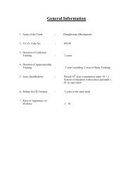
General Information<br />
1. Name of the : Electronic Mechanic<br />
2. N.C.O. Code No. : 852.20<br />
3. Duration of Craftsmen Training : 2 years<br />
4. Duration of Apprenticeship<br />
Training<br />
: 3 years<br />
5. Entry Qualification : Passed in Matriculation Examination under<br />
10 + 2 system of education with Mathematics<br />
and Science or its equivalent.<br />
6. Rebate for Ex-craftsmen : 2 years (Mech. Radio & T. V. or<br />
Trainees<br />
Mech. General Electronics)<br />
7. Ratio of Apprentice to Workers : 1:5
LIST OF MEMBERS OF THE TRADE COMMITTEE<br />
CHAIRMAN<br />
Shri P.K. Chakraborty<br />
Director<br />
CSTARI, Calcutta<br />
MEMBERS<br />
S/Shri<br />
1. B. Sarkar, Rifle Factory<br />
Asstt. Works Manager Ishapur<br />
2. Debal Kr. Roy, Keltron, Calcutta<br />
Service In-charge<br />
3. D. Basu ERTL, Calcutta<br />
Jt. Director<br />
4. U.D. Bhatia S.I.S.I.<br />
Asstt.Director<br />
Calcutta<br />
5. A.K. Das Sharma Peico Electronics Ltd.<br />
Trg. Officer<br />
Calcutta<br />
6. N.C.Samanta BARC, Calcutta<br />
7. B.K.Majumdar ECIL, Calcutta<br />
8. P.K. Biswas B.I.S.<br />
Jt. Director<br />
Calcutta<br />
9. B.A. Ingwle I.T.I. Anudh,<br />
Foreman<br />
Pune<br />
10. S.K. Pal A.I.R.<br />
Station Engineer<br />
Calcutta<br />
11. S.R. Pal CSTARI<br />
Joint Director<br />
Calcutta<br />
SECRETARY<br />
B.K. Chatterjee<br />
Training Officer<br />
CSTARI,<br />
Calcutta.
SYLLABUS FOR THE TRADE OF LECTRONIC MECHANIC<br />
UNDER CRAFTSMEN TRAINING SCHEME<br />
Period of Training: 2 years<br />
Note:<br />
1. The syllabus given below is a guide for the Instructors to prepare their own<br />
Schedule of training. The portion in respect of different subjects which has<br />
been indicated against different weeks may be adjusted according to the<br />
training schedule prepared by the Instructors concerned. While teaching<br />
Engineering Drawing, emphasis should be laid on free hand sketching, blue<br />
print reading, drawing of circuits and parts related to the trade. Similarly<br />
emphasis should be given on problems related to the trade according to the<br />
syllabus given for Workshop Calculation and Science.<br />
Note : 2. BIS Publications for components and measurements for Radio and TVs are<br />
available as standard publications. The Instructors should emphasis the use<br />
of these specifications during course of teaching.<br />
No. of<br />
Weeks<br />
Syllabus<br />
List<br />
Theory Practical Equipment<br />
Required<br />
Engineering<br />
Drawing<br />
1 2 3 4 5 6 7<br />
1. Know<br />
your<br />
Institute<br />
(a)Organization of<br />
the Institute<br />
Departments<br />
various trades &<br />
functions<br />
(b) Types of work,<br />
responsibility to be<br />
undertaken,<br />
incentives and<br />
future. Planning of<br />
profession<br />
©Safety<br />
precautions to be<br />
observed in the<br />
trade oath during<br />
‘Theoretical<br />
Periods’ and<br />
‘Practical<br />
hours/workshop<br />
hours.’<br />
(d) Elementary<br />
First Aid<br />
(e)Earthingtypes<br />
and importance.<br />
(a) Visit to the<br />
Institute<br />
(b) Introduction with<br />
the Principal & other<br />
teaching<br />
staffs.<br />
© Demonstration of<br />
various systems of<br />
the ‘Trade’ like<br />
Radio, Tape, and<br />
T.V. controls, etc.<br />
(d) Care & Safe<br />
working habits,<br />
safety precautions to<br />
be demonstrated to<br />
the trainees.<br />
(e) ‘Elementary First<br />
Aid’ practice,<br />
‘Artificial<br />
respiration’<br />
practice<br />
Power<br />
Supply<br />
switch<br />
gears. Fire<br />
extinguishe<br />
rs<br />
First Aid<br />
Kit<br />
First Aid<br />
Chart<br />
Artificial<br />
Respiration<br />
Chart<br />
Instrument<br />
boxes and<br />
Drawing<br />
materials<br />
Students<br />
tool kits<br />
and<br />
workshop<br />
tools<br />
What is<br />
Engineering<br />
Drawing?<br />
Importance,<br />
Free hand<br />
sketching of<br />
St.lines,<br />
rectangles,<br />
square, circles,<br />
polygons, etc.<br />
Free hand<br />
sketching of<br />
tools. Reading<br />
of simple<br />
drawings and<br />
concept of<br />
dimensions and<br />
dotted lines,<br />
chain line etc.<br />
Magnifying<br />
glass<br />
Workshop<br />
Calculation&<br />
Science<br />
Introduction<br />
to electricity<br />
supply<br />
systems.<br />
Properties<br />
and uses<br />
metals and<br />
non-metals<br />
related to<br />
trade.<br />
Copper,<br />
Zinc, Tin<br />
Aluminum,<br />
Brass,<br />
Bronze<br />
2. & 3. Hand<br />
Tools<br />
Identification,<br />
specifications, uses<br />
and maintenance<br />
Demonstration &<br />
uses of trade hand<br />
tools-Screw-
of hand tools<br />
driver,plier,etc.Simpl<br />
e mechanical<br />
fixtures, types of<br />
screws, bolds,<br />
washers, clamps,<br />
rivets, taps,<br />
connectors.<br />
Simple fitting<br />
practice, fitting and<br />
drilling practice.<br />
Simple threading<br />
practice<br />
Simple sheet metal<br />
works.<br />
Demonstration on<br />
Pneumatic screw<br />
driver.<br />
4. Introduction<br />
to<br />
Electricity<br />
Matter, molecule,<br />
atom, conductor,<br />
Insulator, Semiconductor,<br />
Classifications,<br />
voltage, current,<br />
resistance, Ohm’s<br />
Law, specific<br />
resistance &<br />
O.S.W.G.<br />
5.&6. Resistors Classification of<br />
resistors with<br />
specifications &<br />
use. Construction<br />
of resistors. Colour<br />
Code.<br />
Kirchhoff’s Law<br />
and its application.<br />
Explanation and<br />
only use of<br />
multimeter<br />
Identification of<br />
conductors,<br />
Insulators, with<br />
specifications.<br />
Use S.W.G.<br />
demonstrations of<br />
different soldering<br />
iron. Practice of<br />
soldering & desoldering.<br />
Practice of simple<br />
series and parallel<br />
ckts and mixed.<br />
Verification of<br />
OHM’s Law.<br />
Identification of<br />
resistors. Colour code<br />
practice. Use of<br />
multimeter<br />
measurement of<br />
voltage, current and<br />
resistance.<br />
Experiments on<br />
P.T.C.resistors<br />
“““N.T.C.<br />
resistors<br />
“ “ “ Thermister<br />
resistors<br />
PTC VCR<br />
Resistors<br />
PTC LCR<br />
Resistors<br />
Tests on and use of<br />
classified resistors<br />
Carbon (various W),<br />
W/W, PCT(Log &<br />
Linear) Pre-set,etc.<br />
S.W.G.<br />
Multimeter<br />
soldering<br />
iron.<br />
Temp.<br />
controlled<br />
soldering<br />
station.<br />
SWG<br />
Millimeter<br />
Soldering<br />
iron.<br />
Lead acid<br />
Battery,<br />
cells,<br />
Multimeter.<br />
Reading of<br />
simple drawing,<br />
Free hand<br />
sketching of<br />
simple solids<br />
with dimension<br />
Free hand sketch<br />
of solids viewed<br />
perpendicularly<br />
to their surface<br />
and axes<br />
Solder<br />
Timber,<br />
Rubber Diff.<br />
types of<br />
P.V.C.<br />
Materials<br />
used in<br />
Electronic<br />
Industry.<br />
Use of diff.<br />
Sheets<br />
ferrous and<br />
non-<br />
Ferrous.<br />
Decimals<br />
addition,<br />
subtraction,<br />
Multiplicatio<br />
n,<br />
division ,con<br />
version of<br />
decimals to<br />
common<br />
fractions and<br />
vice versa.<br />
7. Battery Explanation of<br />
cells. Leclanches<br />
cell. Primary cells,<br />
Secondary cells,<br />
Battery<br />
constructioncharging<br />
rate.<br />
Efficiency-<br />
Amp.hr.capacity.<br />
Testing of primary<br />
and secondary cells.<br />
Use of cells and<br />
battery in ckts.<br />
Preparation of<br />
Electrolyte.Preparation<br />
of Charging by a<br />
charger.<br />
Use of sp.gr.tube/<br />
Assorted<br />
cells and<br />
batteries<br />
Assorted<br />
rheostat,<br />
Hydromete<br />
r. Battery<br />
charger,<br />
Battery<br />
Free hand<br />
sketches of nuts<br />
& bolts with<br />
dimensions from<br />
samples. Ckts<br />
and wiring<br />
diagram.<br />
Reduction of<br />
common<br />
fraction to<br />
decimals<br />
fractions.<br />
Brief<br />
description<br />
of<br />
manufacturin
Types of charging-<br />
Silver oxide.<br />
L.C.R.bottom<br />
cells. Alkali cellsconstructioncharging<br />
efficiency-use,<br />
advantages.<br />
Hydrometer<br />
Tester,<br />
Cells<br />
Tester<br />
g process of<br />
steel, copper,<br />
aluminium.<br />
8.& 9<br />
10.&11.<br />
Electro-<br />
Magnetic<br />
Alternati<br />
ng<br />
Current<br />
12. Inductan<br />
ce<br />
Demonstration on the<br />
properties of P.M.<br />
Use of magnetic<br />
needle.<br />
Simple practice of<br />
converting a<br />
magnetic materials<br />
into a magnet by a<br />
bar magnet.<br />
Preparation of a<br />
solenoid. Use of<br />
magnetic needle.<br />
Preparation of a<br />
solenoid. Use of<br />
magnetic needle.<br />
Preparation of<br />
electro-magnets for a<br />
calling bell/buzzer.<br />
Preparation of E.M.<br />
relay. Testing of<br />
types of relays.<br />
Rewinding of E.M.<br />
Relays & small<br />
repairs.<br />
Building of E.M.F. in<br />
a Generator starting<br />
of a D.C. Shunt<br />
motor<br />
Demonstration of<br />
A.C. & D.C.<br />
Demonstration on<br />
Induced E.M.F.<br />
Demonstration on<br />
L.H. & R.H. Rules.<br />
Demonstration on<br />
Instantaneous values<br />
and R.M.S. values.<br />
Demonstration on<br />
phase, cycle, ‘f’<br />
Measurement A.C.<br />
voltages and current<br />
Principle<br />
classification uses.<br />
Identification of<br />
assorted inductive<br />
reactance’s-checking,<br />
testing & rewinding<br />
unto a specification.<br />
Impedance &<br />
P.F.measurements.<br />
Assorted<br />
paramagnet<br />
s. Magnetic<br />
needles.<br />
Assorted<br />
Bells &<br />
Buzzers.<br />
Assorted<br />
relays.<br />
D.C.Shut<br />
generators/<br />
motor.<br />
Small<br />
assorted<br />
D.C.<br />
motors.<br />
Oscillo-<br />
Scope A.C.<br />
Auto var<br />
Models on<br />
L.H. &<br />
R.M.rules.<br />
Low<br />
Frequency<br />
Oscillator<br />
Multimeter<br />
‘f’<br />
Counter<br />
Explanation of<br />
magnetism.<br />
Classification of<br />
magnets and their<br />
materials.<br />
Properties of<br />
magnets, uses and<br />
preparation of<br />
artificial magnets.<br />
Magnetic neddle.<br />
Magnetic keepers.<br />
Explanation of<br />
Electromagnetism.<br />
Properties<br />
advantages,<br />
disadvantagesapplication-types<br />
of cores.<br />
E.M.relays-typesuses.<br />
Concept of<br />
generators &<br />
motors only.<br />
Principle<br />
classification. To<br />
build up E.M.F.in<br />
a generator only<br />
starting of a<br />
D.C.motor only<br />
miniature motors.<br />
Explanation of<br />
A.C.Comparison<br />
with D.C.Expl. of<br />
Induction &<br />
induced E.M.F.<br />
Faraday’s Law,<br />
Lenz’s Law A.C.<br />
Generator-Left<br />
hand and Right<br />
hand rules.<br />
Instantaneous<br />
valves<br />
R.M.S.VALUES-<br />
Phase-cycle-Time<br />
period-frequency.<br />
Single phase<br />
motor. Three phase<br />
motor. Fractional<br />
H.P.Motors..Capacitor<br />
motor<br />
Define-Inductance.<br />
Explanation of<br />
Inductive<br />
reactance, types<br />
specification.<br />
Behavior with<br />
A.C.Impedence.<br />
Coil concept-<br />
Oscillo-<br />
Scope A.C.<br />
Auto Var<br />
Models on<br />
L.H.&R.H.<br />
Rules.<br />
Low<br />
frequency<br />
Expl.of simple<br />
orthographic<br />
projection 1 st<br />
angle.<br />
Expl. Of simple<br />
Orthographic<br />
Projection<br />
3 rd angle.<br />
Expl. of simple<br />
Orthographic<br />
Projection<br />
3 rd angle.<br />
Metric<br />
system<br />
metric<br />
weights and<br />
metric<br />
measurement<br />
s, units<br />
conversion<br />
factors.<br />
Manufacture<br />
of plastic and<br />
resims.<br />
Meaning of<br />
tenancity<br />
Elasticity<br />
Malleability<br />
brittleness<br />
hardness<br />
compressibili<br />
ty and<br />
ductility with<br />
examples.<br />
The weight<br />
of a body,<br />
units of<br />
weights &<br />
shop<br />
problem<br />
percentage &<br />
its
Resonance<br />
14 to 16 Simple<br />
Analogu<br />
e<br />
Meters<br />
power factor. Self<br />
&mutual<br />
induction coefficient<br />
of<br />
coupling.<br />
Expl. Of<br />
Transformer-typesturns<br />
ratio-useslosses-efficiency.<br />
Hysterisis & eddy<br />
current-types of<br />
cores to be used<br />
for L.F.H.F.<br />
&V.H.F.<br />
Transformer.<br />
Expl.of<br />
capacitance &<br />
capacitive<br />
reactance.<br />
Classification of<br />
capacitors with<br />
specification<br />
Electrostatic action<br />
dielectric<br />
constants,<br />
materials used.<br />
Series and parallel<br />
Connection.<br />
Colour cores uses.<br />
Expl.of resonance.<br />
Importanceequations<br />
Series<br />
and parallel<br />
resonance.<br />
Ckt.elementsnatural<br />
resonance,<br />
tuning, voltage<br />
gain Antiresonance<br />
ckt.of<br />
faster.<br />
Uses in electronic<br />
ckts.<br />
What is meter ?<br />
Importance of<br />
meter.<br />
Classification of<br />
meter. Forces<br />
necessary to work<br />
a meter. M.C.<br />
Instruments. M.I.<br />
Instruments.<br />
Universal<br />
Instruments. Range<br />
Extension of<br />
meters. Need of<br />
calibration.<br />
Multimeter.<br />
Characteristics of<br />
meters.<br />
Use of meters in<br />
different ckts.<br />
Use of<br />
multimeters.<br />
Servicing, care &<br />
maintenance.<br />
Use of Insulation<br />
tester.<br />
Demonstration on<br />
self and mutual<br />
induction.<br />
Identification of<br />
assorted<br />
transformers-testing<br />
and rewinding up to a<br />
specification.<br />
Identification and<br />
testing of different<br />
types capacitors.<br />
Colour code practice.<br />
Behaviour of<br />
capacitor at different<br />
frequencies<br />
Determination of<br />
resonance.<br />
Characters for series<br />
and parallel.<br />
Turning to a given ‘f’<br />
Demonstration on the<br />
function of M.C. &<br />
M.I. meters<br />
Measurement of<br />
resistance, voltage,<br />
current frequency,<br />
etc. by Am-meter,<br />
Voltmeter, frequency<br />
meter. Expts on<br />
‘range extension’ of<br />
meters.<br />
Use of multimeters.<br />
Servicing of<br />
multimeters.<br />
Servicing of<br />
multimeters.<br />
Demonstration on<br />
calibration of meters<br />
Demonstration on<br />
insulation tester.<br />
Oscillator.<br />
Multimeter<br />
‘f’ counter<br />
Assorted<br />
Inductive<br />
reactances.<br />
Assorted<br />
Transforme<br />
rs.<br />
13. Capacitance.<br />
Bridges-<br />
RCL or<br />
Digital<br />
Multimeter,<br />
Power<br />
supply,<br />
Oscillator,<br />
E.V.M.<br />
Oscilloscop<br />
e, signal<br />
generator<br />
E.V.M.<br />
Assorted<br />
analogue<br />
meters.<br />
Multimeter<br />
s. Models/<br />
Kits for<br />
assorted<br />
Ckts. Shunt<br />
&series<br />
Resistors.<br />
Standard<br />
Meters.<br />
Expl.of simple<br />
orthographic<br />
projection 3 rd<br />
angle.<br />
Simple isometric<br />
drawings,<br />
isometric views<br />
of simple<br />
objects such as<br />
square, cube<br />
rectangular<br />
blocks. Detailed<br />
diagram of<br />
Electromagnets.<br />
Familiarising<br />
and sketching<br />
the details of<br />
components.<br />
application.<br />
Shop<br />
problems.<br />
C.G.S.M.K.S<br />
And their<br />
conversion<br />
problem.<br />
Ratio and<br />
proportion<br />
shop<br />
problems,<br />
plotting and<br />
reading of<br />
simple<br />
graphs.<br />
Works unit<br />
of work,<br />
energy<br />
power.<br />
Applied<br />
problems.<br />
Algebraic<br />
symbols<br />
addition,<br />
subtraction,<br />
multiplication<br />
division.<br />
Standard<br />
algebraic<br />
formula<br />
(a+b)2.<br />
Simple<br />
simultaneous<br />
equations<br />
with two unknown<br />
measuring of<br />
friction<br />
examples,<br />
meaning of<br />
C.G.
17. Semi-<br />
Conductor<br />
Define ‘Semiconductor’<br />
Intrinsic &<br />
Extrinsic semiconductors.<br />
Temperature coefficient.<br />
Definition of ‘P’<br />
and ‘N’ types of<br />
semi-conductor.<br />
Development of<br />
P.N.Junction-<br />
Barrier potential<br />
symbol.<br />
Symbolsasper<br />
B.I.S./graphic.<br />
18 to 19 DIODE Expl. of Diode<br />
Classifications of<br />
Diodes. Characters<br />
of Diode. Zener<br />
diode.<br />
Temperature<br />
effect. Diode as<br />
rectifier-Half<br />
wave-Full wave<br />
Bridge<br />
CodingofDiodes.<br />
Study of the diode<br />
function<br />
parameter.<br />
20. Filter<br />
Circuits<br />
21. to<br />
23`<br />
24<br />
to<br />
26<br />
Transistor<br />
Amplifie<br />
r<br />
What is filter<br />
circuits?<br />
Types of Filter<br />
circuits.<br />
expl.of XC ,X L.<br />
Hipass, Low pass,<br />
Band pass filters<br />
Bi-polar junction<br />
Device.<br />
Expl. of transistor.<br />
Types of transistor.<br />
Tests of transistor.<br />
Symbol as per<br />
B.I.S.Biasing of<br />
Transistor & mode<br />
of application.<br />
Arrangement of a<br />
Transistor in a ckt.<br />
Conditions for the<br />
use of a transistors,<br />
current flow in a<br />
transistor, ALPHA<br />
&BETAofa<br />
transistor. Thermal<br />
run way,<br />
Transistor CB, CC,<br />
CE amplification.<br />
Explanation of<br />
Amplifier ‘f’<br />
spectrum.<br />
Classification of<br />
Amplifiers, Class<br />
Film on Semiconductor.<br />
Film on<br />
P.N. Junction.<br />
Demonstration on<br />
Barrier-Potential for<br />
G&Si.<br />
Testing of a Diode.<br />
Characteristics of<br />
Diode.<br />
Characteristics of<br />
Zener-diode.<br />
Half wave rectifier<br />
ckt.<br />
Full wave rectifier<br />
Ckt.<br />
Bridge rectifier ckt.<br />
Demonstration on<br />
various filter ckts.<br />
Assembly, testing &<br />
‘L’ ‘T’ & PAI filters<br />
Demonstration on<br />
H.P., L.P., & B.P.<br />
Filter circuits.<br />
Identification and<br />
testing of a transistor.<br />
To study alpha &<br />
Beta of a<br />
transistor/characterist<br />
ics of a transistor<br />
(Static and<br />
Dynamic). To study<br />
the function of a<br />
transistor as an<br />
amplifier.<br />
Demonstration,<br />
assembly and testing<br />
of a transistor<br />
amplifier in Class<br />
A,B,C, P-P<br />
Video<br />
Films on<br />
Semi-<br />
Conductor<br />
Video<br />
Films on<br />
P.N.<br />
Junction<br />
Digital<br />
Multimeter<br />
Multi-<br />
Meter<br />
E.V.M.<br />
Oscilloscope<br />
Multi-<br />
Meter oscilloscope<br />
Multimeter,<br />
milliammeter,<br />
microammeter,<br />
millivoltmeter.<br />
Transistor<br />
tests.<br />
Signal<br />
Generator.<br />
Oscilloscope<br />
Multimeter,<br />
D.C.Low<br />
voltage<br />
power<br />
supply.<br />
Use of drawing<br />
instruments. ‘T’<br />
Square, drawing<br />
board<br />
construction<br />
Of simple<br />
figures & solids<br />
with<br />
dimensions.<br />
Use of different<br />
types of scales<br />
in inch &<br />
millimeters.<br />
Lettering<br />
numbers and<br />
alphabets.<br />
Specification<br />
gravity<br />
Balancing<br />
examples.<br />
Areas of<br />
rectangles,<br />
circles,<br />
regular,<br />
polygons,<br />
Calculation<br />
of areas,<br />
volume,<br />
weight of<br />
simple<br />
solids-cubes<br />
squares,<br />
hexagonal<br />
prisms shop<br />
problems.<br />
--- Heat and<br />
temperature<br />
thermometric<br />
scales-<br />
Fahrenheit,<br />
centigrade<br />
and t heir<br />
conversion<br />
Kelvin<br />
Reamer<br />
Celsius.<br />
Drawing of<br />
various<br />
electrical ckts.<br />
With<br />
B.I.S.symbols of<br />
ckt.series and<br />
parallel ckt.<br />
Power<br />
transformer<br />
instrument<br />
transformer,etc.<br />
Free hand<br />
sketching of<br />
plan & elevation<br />
of simple<br />
objects-<br />
Meaning of<br />
stress<br />
modules of<br />
Elasticity,<br />
ultimate<br />
strength B-<br />
11 curve.<br />
Simple<br />
problems on<br />
Lines,<br />
angles,<br />
triangles and
27 to 30 Power<br />
Supply<br />
31 to 33 Stereo<br />
system<br />
A.B.C.A-B<br />
A.F.amplifierwave<br />
– length,<br />
propagation, Val.<br />
of sound, Hifi,<br />
.R.F. amplifier.<br />
Voltage amplifier.<br />
Small signal,<br />
Large signal,<br />
Signal to noise<br />
ratio. Power<br />
amplifier-types.<br />
Push-pull,<br />
Complementary<br />
symmetry<br />
(transformeters out<br />
put)<br />
Thermal stability<br />
and heat<br />
dissipation.<br />
Biasing and<br />
couplings.<br />
Frequency<br />
compensation, preamplifier.<br />
Cascading of<br />
amplifiers. FC of<br />
amplifier.<br />
Vol.control tape<br />
control, bass<br />
control, Treble<br />
control and master<br />
control P.A.<br />
system.<br />
Explanation of<br />
power supply,<br />
Importance, typesun<br />
regulated,<br />
regulated-types of<br />
regulation.<br />
Stabilizers-types.<br />
On S.M.P.S.<br />
Blocks Investor<br />
ckts. And<br />
convatorckts.<br />
Blocks of U.P.S.<br />
Explanation of<br />
sound propagation,<br />
sound, importance<br />
of channels in<br />
sound system.<br />
Explanation of<br />
microphonestypes,<br />
uses<br />
specifications etc.<br />
Explanation of<br />
Loud-Speakerstypes<br />
matching of<br />
speakers/Horns/<br />
Baffles/enclosures.<br />
complementary<br />
symmetry modes.<br />
Assembly, testing<br />
and frequency<br />
response of a single<br />
stage A.F. amplifier<br />
and R.F. amplifier.<br />
Assembly, testing<br />
and frequency<br />
response of a five<br />
stage amplifier with<br />
voltage amplifier and<br />
power amplifier.<br />
StudyofP.C.B.ofan<br />
amplifier. Fault<br />
location and<br />
servicingofa<br />
amplifier. Study of<br />
Vol.tone, Bass,<br />
Treble and master<br />
control ckts.<br />
Demonstration of<br />
various power<br />
supply. Assembly &<br />
testing of an<br />
unregulated power<br />
supply. Assembly &<br />
testing of a series<br />
regulated, shunt<br />
regulated F.S.<br />
Assembly & testing<br />
of a voltage stabilizer<br />
as per specifications<br />
to be used for a T.V.<br />
Refrigerator.<br />
Demonstration on<br />
U.P.S. system.<br />
Assembly & testing<br />
of a S.M.P.S. for<br />
C.T.V.<br />
Demonstration and<br />
testing of various<br />
microphones.<br />
Identification, testing<br />
servicing of<br />
microphone spares.<br />
Identification testing<br />
& servicing of Loud<br />
Speakers.<br />
Arrangement of<br />
speaker/Horns in a<br />
room/ Auditorium &<br />
for a open gathering.<br />
Impedence matching.<br />
Signal<br />
generator.<br />
A.F.<br />
-Do-<br />
R.F.HF<br />
oscilloscop<br />
eoutput<br />
meter.<br />
Reading of<br />
simple ckts.<br />
Assorted<br />
microphones.<br />
Assorted<br />
Loud-<br />
Speakers.<br />
Assorted<br />
Horns A.F.<br />
amplifier<br />
Line<br />
transformer<br />
.Multi<br />
channel<br />
stereo<br />
hexagonal bar,<br />
Sq.bar, circular<br />
bar, tapard bar,<br />
hollow bar, etc.<br />
Calculation of<br />
areas of<br />
triangles.<br />
Polygons with<br />
the aid of<br />
trigonometry.<br />
Symbols as per<br />
different semiconductor<br />
devices L.D.R.,<br />
V.D.R.<br />
thermister, &<br />
their use in ckts.<br />
circles.<br />
Calculation<br />
of current<br />
voltage, in<br />
voltage<br />
dividing net<br />
work using<br />
thermister,<br />
V.D.R.,<br />
L.D.R. at<br />
different<br />
temp.,<br />
voltage, light<br />
intensity etc.
Line transformers.<br />
Explanation of<br />
stereo system.<br />
Stereo amplifiers.<br />
Arrangement of<br />
stereo for a<br />
specified area.<br />
Surround sound<br />
systems.<br />
34 to 35 Intercom Definition &<br />
Explanation of<br />
‘Intercom’ system.<br />
Block diagram of<br />
‘Intercom’ system.<br />
Explanation of<br />
cradles/ Receiver<br />
types, function and<br />
testing.<br />
Explanation of<br />
‘Ex-changes’ used,<br />
Explanation of<br />
36 to 38 Oscillato<br />
r<br />
power supply.<br />
Define oscillator<br />
Importance,<br />
applications to<br />
electronic<br />
Ckts<br />
Explanations of<br />
vibration and<br />
oscillation.<br />
Factors controlling<br />
oscillations Types-<br />
A.F.-R.F. Feed<br />
back, Tank ckts,<br />
crystal oscillator,<br />
Oscillators-used in<br />
Radio ckts,<br />
T.V.ckts. Tape<br />
recorder. etc.<br />
Function<br />
Generator other<br />
applications of<br />
oscillators. Tone<br />
generation,<br />
Remote etc.<br />
Demonstration on<br />
2/4/6 channel stereo<br />
system.<br />
Demonstration of<br />
‘Intercom’ system.<br />
Studyofcradles/<br />
Receiver study of<br />
Exchanges. Study of<br />
power supply of<br />
‘Intercom’ system.<br />
Fault finding and<br />
Servicing of<br />
‘Intercom’ system.<br />
Demonstration on<br />
various oscillators.<br />
StudyofFeedbackin<br />
an oscillator ckt.<br />
Assembly of an A.F.<br />
oscillator testing &<br />
measuring the ‘f’ of<br />
generated<br />
oscillations.<br />
StudyofanR.F.<br />
oscillator. Fault<br />
finding & servicing<br />
of oscillator.<br />
system.<br />
Multimeter<br />
E.V.M.<br />
oscilloscop<br />
e<br />
12 line<br />
intercom<br />
system<br />
with<br />
‘exchange’<br />
Multimeter.<br />
Various AF<br />
&RF<br />
oscillators.<br />
Multimeter<br />
oscilloscop<br />
e.<br />
Frequency<br />
counter.<br />
Remote<br />
control<br />
Devices-<br />
Toys etc.<br />
Drawing of A.F.<br />
amplifier ckt.<br />
With six stage<br />
and with types<br />
of out-put P-P.<br />
Block diagram<br />
of an oscillator.<br />
Symbols for<br />
different wave<br />
shapes – square,<br />
Saw tooth, Sine,<br />
Triangular etc.<br />
To calculate<br />
current in<br />
different<br />
resistive net<br />
work using<br />
Diode.<br />
Zener in F.B.<br />
&R.B.<br />
Calculation<br />
of ‘f’<br />
V from f=v<br />
Time period<br />
Giga heat z<br />
Mega heat z<br />
Micro etc,<br />
39 Modulation<br />
40 to 42 Radio<br />
Receivers<br />
Define modulation<br />
types of mode-<br />
A.M. F.M., P.M. –<br />
application<br />
Broadcasting.<br />
Bandwidth mode<br />
index. Definition<br />
and importance<br />
and démodé.<br />
Full explanation of<br />
Radio receiver<br />
Superheterodyne<br />
principle of<br />
‘frequency<br />
changing’ chain,<br />
termsusedinradio<br />
transmission-<br />
Ionosphere, ground<br />
wave propagations<br />
Electromagnetive<br />
Demonstration on a<br />
multiband Radiko<br />
Receiver.<br />
Studyofradiockt.<br />
M.W.<br />
-DO- Multiband.<br />
Identification of R.F.<br />
stage.<br />
Identification of I.F.<br />
stage<br />
Identification of A.F.<br />
Assorted<br />
Radio<br />
Receivers<br />
(Multiband<br />
)<br />
Multimeter<br />
oscilloscope<br />
Drawing of AM<br />
&FM<br />
modulated wave<br />
at various<br />
nmodulation-<br />
100 pc, 50 pc.<br />
Etc.<br />
Exercise on<br />
Blue print<br />
reading/ckt.<br />
Reading of<br />
house service<br />
connections and<br />
small power<br />
ckts. Connection<br />
of Ammeter<br />
Volt meter,<br />
Watt-meter Kwh<br />
Determination<br />
of<br />
Velocity<br />
ratio,<br />
mechanical<br />
advantage &<br />
efficiency<br />
Logarithm.<br />
Use of logtables<br />
for<br />
multiplicatio<br />
nand<br />
division.<br />
Determination<br />
of<br />
efficiency of<br />
simple<br />
machines-
43. Tuning<br />
Section<br />
(R.F.<br />
Section)<br />
44. I.F.<br />
Stage<br />
And<br />
Detection<br />
45. Audio<br />
Stage<br />
waves, reflection,<br />
speed of<br />
transmission, wave<br />
length.<br />
Explanation of<br />
‘frequency’ ranges<br />
Resonance. Image<br />
frequency,<br />
acceptor ckt. &<br />
rejector ckt.<br />
Disadvantages of<br />
R.F. amplification.<br />
Sensitivity and<br />
selectivity.<br />
Fideality. Singnal<br />
to noise ratio.<br />
Block diagram of a<br />
radio receiver.<br />
Explanation of<br />
tuning section/R.F.<br />
Section. Block<br />
diagram<br />
Antenna ckt.<br />
Oscillator ckt.<br />
Mixer stage. I.F.<br />
generation. R.F.<br />
amplifier A.G.E.,<br />
types of transistors<br />
used.<br />
Specifications of<br />
Ant. & oscillator<br />
coils with types of<br />
‘Gang condensers.’<br />
Types of ‘band’<br />
switches. Usedconnections<br />
conditions for<br />
better selectivity<br />
ant. Sensitivity.<br />
Explanation of I.F.<br />
the importance of<br />
I.F. range for<br />
M.W. & S.W. Ckt.<br />
Analysis of I.F.<br />
stage.<br />
Transistors/I.C.<br />
used their<br />
characters.<br />
Alignment of I.F.<br />
stage.<br />
Explanation of<br />
detection/demodul<br />
ation.<br />
R.F. by pass.<br />
Tuning indicators<br />
with their ckt.<br />
Arrangement<br />
types.<br />
A.V.C./A.G.C.<br />
Line, importance.<br />
Explanation of<br />
audio stage, types<br />
of amplification,<br />
driver stage, output<br />
stage. Transistors<br />
used.<br />
Tone control, Vol.<br />
stage.<br />
Study of assorted<br />
‘Bank Switches’<br />
Practice on ‘Dial<br />
Threading’<br />
Study of the PCB of<br />
the R/Rckt.<br />
StudyofR.F.section<br />
of R/Rs for both<br />
P.N.P./N.P.N. Ant. &<br />
oscillator alignments.<br />
Study of different<br />
band switches. Fault<br />
finding and servicing<br />
of R.F. stage.<br />
Checking of<br />
selectivity. Checking<br />
of sensitivity.<br />
StudyofI.F.Stageof<br />
R/R for both<br />
PNP/NPN.<br />
Studyofdetector<br />
stage of R/R/ for both<br />
PNP/NPN.<br />
Study of<br />
A.V.C./S.G.C. ckt.<br />
Alignment of I.F.T.<br />
for desired I.F. for<br />
desired I.F. Testing<br />
of I.F.T.s.<br />
replacement of<br />
I.F.Ts. and<br />
realignment.\<br />
Fault finding by<br />
meter/by signal<br />
traces/by scope.<br />
StudyofAudiostage,<br />
driver stage, output<br />
stage, tone and vol.<br />
Control stage.<br />
Fault finding and<br />
servicing.<br />
R/R-both<br />
P.N.P. and<br />
N.P.N.<br />
Multimeter<br />
signal<br />
generator.<br />
Oscilloscope<br />
D.C.<br />
power<br />
supply<br />
R/R-both<br />
N.P. and<br />
N.P.N.<br />
Multimeter<br />
E.V.M.<br />
Signal<br />
Generator.<br />
Signal<br />
tracer<br />
oscilloscope<br />
-do-<br />
meter with<br />
I.S.I.symbol<br />
ckt.reading and<br />
drawing of<br />
different stages<br />
of R/R/.<br />
Free hand<br />
sketching of<br />
trade objects.<br />
Ckts.of<br />
magnetic<br />
controller with<br />
dynamic<br />
breading.<br />
Drawing of<br />
conversion.<br />
Stage of R/R/<br />
both PNP/NPN.<br />
Layout of<br />
Battery charging<br />
ckt. From D.C.<br />
Shunt generator.<br />
Drawing of I.F.<br />
Stage of both<br />
P.N.P. and<br />
N.P.N. ckts.<br />
Details of<br />
electrical control<br />
panel<br />
Wrench,<br />
pulley<br />
blocks,<br />
wheels and<br />
compound<br />
axles.<br />
Problems of<br />
mensurtion,<br />
Sq.hexagon,<br />
Prism<br />
Atmospheric<br />
pressure,<br />
pressure<br />
gauges,<br />
absolute<br />
pressure<br />
properties of<br />
matter.<br />
Defect of<br />
force on<br />
material in<br />
such<br />
applications<br />
as extending,<br />
bending,<br />
twisting and<br />
shearing.<br />
Trigonometri<br />
ctables,appl<br />
ied<br />
problems.<br />
Calculation<br />
of bias.<br />
Determination<br />
of gain<br />
of air at<br />
different<br />
load.
46 to 48 Fault<br />
Finding<br />
49 to 50 Record<br />
Player &<br />
Changer<br />
Control.<br />
Preparation of<br />
servicing charts for<br />
fault finding in<br />
Audio Amplifiers<br />
are in R/Receivers.<br />
Data sheet &<br />
history sheet.<br />
Replacement<br />
charts/equivalent<br />
charts.<br />
Expl.of record<br />
player and record<br />
changer, block<br />
diagrams.<br />
Principle of<br />
operation of<br />
pickup (types)<br />
speed changer,<br />
mechanical<br />
assembly.<br />
Stylus adjustment,<br />
replacement study<br />
of the motors and<br />
speed control.<br />
Servicing practices<br />
Demonstration on<br />
Record player and<br />
record changer.<br />
StudyofRecord<br />
Player.<br />
StudyofRecord<br />
changer.<br />
Identification, testing<br />
& replacement<br />
various pick ups,<br />
idlers and motorsspeed<br />
testing by<br />
stroboscope.<br />
Signal<br />
tracer<br />
Oscilloscope<br />
Record<br />
player<br />
Record<br />
changer<br />
stroboscope<br />
.<br />
51. REVISI<br />
ON<br />
+Need of<br />
standards-types of<br />
standards<br />
+National<br />
standards-diff.<br />
standard bodiesimplementation.<br />
52 T E S T<br />
Drawings of<br />
C.B.,C.E.&<br />
C.C. Ckts<br />
Typical voltage<br />
Amplifier ckt<br />
Drawing of<br />
Class A & B<br />
amplifier ckt.<br />
Different power<br />
output stages P-<br />
P<br />
complementary<br />
symmetry etc.<br />
Drawing of the<br />
mechanical<br />
assembly of<br />
speed changer.<br />
Drawing of<br />
transistorized<br />
R/R set<br />
Simple<br />
calculation<br />
of power<br />
output and<br />
ilasing.<br />
Simple<br />
problems on<br />
lefting<br />
devices.<br />
Solution of<br />
problems by<br />
vectors. Ex.<br />
On simple<br />
supported<br />
load.<br />
Calculation<br />
of area Vol.<br />
And weight<br />
of simple<br />
solids<br />
bodiescubes,<br />
squares,<br />
hexagons,<br />
prism,.<br />
Achieve<br />
ment:<br />
53 to 58 Tape<br />
Recorder<br />
And<br />
Compact<br />
Disc.<br />
At the end of first<br />
year, trainees will<br />
be in a position to<br />
assemble/test and<br />
repair different<br />
power supplier,<br />
Audio amplifier<br />
and A.M. radio<br />
receivers<br />
Expl.of magnetic<br />
recording principle<br />
with block diagram<br />
types. Function &<br />
use of magnetic<br />
tapes, recording<br />
heads, erasing<br />
heads. Bias<br />
oscillator. Doily<br />
system. Motors<br />
used and speed<br />
control speeds of<br />
tapes. Care and<br />
maintenance idea<br />
of stereophonic<br />
Demonstration on<br />
magnetic recording,<br />
play back, fast<br />
forward and Rewind<br />
Studyofrecording<br />
and erasing circuit.<br />
Study of Mechanical<br />
Assemble with<br />
motor. Cleaning of<br />
Heads. Fault finding<br />
and Servicing Study<br />
of ‘Auto Stop’.<br />
Study of two-in-one<br />
circuit. Study of a car<br />
stereo circuit.<br />
Tape<br />
Recorder<br />
i)Cassettee<br />
ii) Spool<br />
Multimeter<br />
i)<br />
Block diagram<br />
of a tape<br />
recorder.<br />
Circuit diagram<br />
of C/L relay<br />
Drawing of a<br />
limit switch<br />
Problems of<br />
mensuration<br />
General<br />
condition of<br />
equilibrium<br />
for series of<br />
forces on a<br />
body.<br />
Plotting of<br />
graper.<br />
Simple<br />
problems of<br />
graper.<br />
Brief<br />
description
59 to 61 Special<br />
Semiconducto<br />
rs<br />
62 to 63 Transmit<br />
ter<br />
64 to<br />
65.<br />
66 to<br />
75.<br />
Oscillosc<br />
ope.<br />
Televisio<br />
n<br />
systems.<br />
recording and<br />
reproduction<br />
system.<br />
Servicing charts.<br />
Specification of<br />
tapes and cassettes.<br />
Idea of standard<br />
Recorder. Idea of<br />
equalizers.<br />
Example of Car-<br />
Stereo system.<br />
Expl. of compact<br />
Disc system.<br />
Expl.of<br />
characteristics,<br />
uses of U.J.T.,<br />
F.E.T.,<br />
M.O.S.,F.E.T.,<br />
S.C.R., S.C.S.,<br />
S.B.S.,C.DIAC<br />
TRIAC,I.C.<br />
Example of<br />
transmission<br />
systems. Block<br />
diagram.<br />
Frequency<br />
multiplier. Feeders<br />
&Antena&Phase<br />
modulation. Police<br />
wireless,<br />
microwave link<br />
and satellite<br />
communication.<br />
(Example & Block<br />
dia only)<br />
Expl. of<br />
oscilloscope,<br />
importance,<br />
applications. Block<br />
diagram.<br />
Introduction to<br />
VALVE only.<br />
Construction &<br />
function of C.R.T.<br />
–C.R.O.Useof<br />
C.R.O. Care and<br />
maintenance.<br />
Lissajer’s fig.<br />
Expl. of T.V.<br />
systems B&W<br />
Block diagrams for<br />
Azimuth correction.<br />
Demonstration on<br />
C.D. player.<br />
Study & assembly of<br />
a U.J.T. triggered ckt<br />
Study and assembly<br />
of F.E.T. amplifier<br />
ckt. Study of a ckt.<br />
Using MOSFET<br />
Studyofackt.S.B.S.<br />
&S.C.S.Studyof<br />
S.C.R. in D.C.<br />
StudyofS.C.R.in<br />
A.C.<br />
Study of voltage<br />
control by S.C.R.<br />
Study of DIAC,<br />
StudyofI.C.ckts.-<br />
amplifier, switching<br />
ckt.<br />
Demonstration on<br />
various transmitting<br />
Systems.<br />
Studyinblocksthe<br />
ckts. Of transmitters.<br />
Demonstration a<br />
C.R.O. Example of<br />
‘X’ & ‘Y’ axes<br />
controls.<br />
Measurements of<br />
D.C. voltages, A.C.<br />
voltages frequency<br />
etc. Comparison of<br />
waver. Use of<br />
‘scope’intesting&<br />
fault location.<br />
Practice on scope for<br />
measurements.<br />
Test on Lissejus<br />
pattern.<br />
Demonstrationona<br />
B&W T.V.<br />
Identification of diff.<br />
Models of<br />
U.J.T.<br />
triggered<br />
ckt. FET as<br />
power<br />
Amplifier.<br />
Models as<br />
S.B.S.<br />
S.C.S<br />
Electronic<br />
power<br />
regulator.<br />
Analogue<br />
I.C. tester.<br />
Mocroproc<br />
essor kit.<br />
Oscillocope<br />
Multimeter<br />
E.V.M.<br />
Function<br />
generator.<br />
Transmitter<br />
(if<br />
available)<br />
C.R.O. ,<br />
L.P. & H.F.<br />
signal<br />
generation<br />
‘VIDEO<br />
FILM’<br />
‘Oscillosco<br />
pe’.<br />
‘Video<br />
film’<br />
‘How T.V.<br />
Drawing of<br />
U.J.T. triggered<br />
ckt. With<br />
I.S.I.symbol.<br />
Power amplifier<br />
ckt.with<br />
F.E.T.,I.S.I.sym<br />
bols of<br />
S.B.S.,S.C.S.vol<br />
tage regulator<br />
ckt. Motor<br />
control ckts.<br />
A.F.amplifier<br />
ckt is I.C.<br />
Remote control<br />
by L.S.I. and<br />
M.S.I. Block<br />
diagram of<br />
microprocessor<br />
Flow chart of<br />
microprocessor.<br />
(if drawing of<br />
ckt. Of signal<br />
generator,<br />
E>V>M><br />
function<br />
generator.<br />
d.c. speed<br />
control ckts.<br />
With I>S>I><br />
symbols.<br />
Drawing of<br />
Block diagram<br />
of oscilloscope,<br />
C.R.T. circuits<br />
diagram of<br />
oscilloscope.<br />
Drawing of the<br />
block diagram<br />
of a T.V. set.<br />
and<br />
properties of<br />
silicon,<br />
Nichrome<br />
silver etc.<br />
Problems on<br />
mesuration<br />
problems.<br />
Atmospheric<br />
pressure.<br />
Pressure<br />
gauges<br />
Absolute<br />
pressure.<br />
Properties of<br />
Matter. The<br />
molecule and<br />
atoms.<br />
Different<br />
between<br />
mass and<br />
weight<br />
Representati<br />
on of forces<br />
by vectors,<br />
simple<br />
problems on<br />
lifting<br />
tackles Jig,<br />
wall cranes<br />
solution by<br />
vectors.<br />
General<br />
condition of<br />
equilibrium<br />
for series of<br />
forces on a<br />
body.<br />
Plotting of<br />
graph.<br />
simple<br />
equation of<br />
graphs.<br />
Trigonometri<br />
c function –<br />
Use of
76 to 83 Colour<br />
T.V.<br />
both. Transmitter<br />
& Receiver. Idea<br />
about video<br />
camera. Scanning<br />
system. Frame,<br />
Field, Raster,<br />
Picture elements.<br />
Composite video<br />
signal. Aspect<br />
ratio, resolution,<br />
flickering,<br />
contrast,<br />
Brightness video<br />
signal, sound<br />
signal channels,<br />
Bands. Expl.data<br />
preparation for<br />
Tuners.-<br />
i)Mechanical<br />
ii)Electronic –do-<br />
Fitter ckt. SWAF –<br />
do- Video<br />
amplifier &<br />
picture tube –dosweep<br />
section &<br />
E.H.T. –do- Sound<br />
Section -do-<br />
Power supply T.V.<br />
Antenna- YAGI &<br />
feeder cables.<br />
Expl.of colour<br />
T.V. Functional<br />
Block diagram.<br />
Expl.ckt.<br />
description and<br />
test points of<br />
Tuner<br />
-do-V.I.F.<br />
-do- A.G.C.<br />
-do-Video<br />
Amplifier<br />
-do-Synchronisation<br />
& sweep ckt.<br />
-do-Matrix<br />
-do-Picture tube<br />
-do-Sound Section<br />
-do-Power supply<br />
Preparation of<br />
servicing<br />
charts/data sheet.<br />
Fault finding step<br />
by step. Balancing<br />
of white colour<br />
Controls.<br />
-do- Tuner, testing &<br />
replacement.<br />
-do- wave trap ckt. &<br />
testing.<br />
-do- video I.F. –do-<br />
-do- staggered tuning<br />
of video I.F.<br />
-do- Video amplifier<br />
–do-<br />
-do- picture tube-do-<br />
-do- sweep ckt.<br />
-do-<br />
-Haizcutal-<br />
E.H.T.<br />
-do- F.M. Sound –dosection.<br />
-do- power supply<br />
-do- S.M.P.S.<br />
-do- S.T.R.<br />
-do- S.T.R.<br />
-do- Preparation<br />
servicing<br />
charts.<br />
Installation of T.V.<br />
Antenna.<br />
Demonstration on<br />
C.T.V. Identification<br />
&useof<br />
diff.controls.<br />
Identification, study<br />
& test points of<br />
Tuner.<br />
-do- V.I.F.<br />
-do-Video Amplifier<br />
-do-Sync.ckt<br />
-do-sweep ckt.<br />
-do-Picture tube<br />
-do-Sound sec.<br />
-do-Power supply<br />
Fault finding.<br />
Adjustment of white<br />
colour<br />
works’.<br />
T.V. sets<br />
B&W<br />
make diff.<br />
Company<br />
With<br />
servicing<br />
manual.<br />
Pattern<br />
generator.<br />
Multimeter<br />
DATA<br />
Book T.V.<br />
demonstrati<br />
on kit.<br />
Sweep<br />
generator<br />
with ‘X-Y’<br />
display.<br />
C.T.V.(diff.<br />
Make with<br />
manual.<br />
Colour<br />
pattern<br />
generator.<br />
Multimeter.<br />
CTV<br />
demonstrati<br />
on. Oscillocope.<br />
Sweep<br />
generator<br />
with ‘X-Y’<br />
Display.<br />
Video film<br />
‘How CTV<br />
works’.<br />
Drawing of<br />
picture tube.<br />
-do- Electronic<br />
gum.<br />
-do- Deffection<br />
yoke.<br />
-do- Speaker<br />
-do- Video<br />
Amplifier ckt.<br />
-do-S.W.A.F.<br />
-do- E.H.T. ckt.<br />
-do- E.H.T.ckt<br />
-do- ‘YAGI’<br />
Antenna<br />
-do- the circuit<br />
of wabbulator.<br />
-do- Vidicon<br />
camera-tube.<br />
Drawing of<br />
different turner<br />
diagrams,<br />
V.H.F. Channel<br />
charts. Typical<br />
video I.F.<br />
response curve,<br />
staggered tuned<br />
amplifier ckt.<br />
F.M.detector<br />
response curve.<br />
Sound section<br />
ckt. Diagram<br />
trigonometri<br />
ctables.<br />
Applied<br />
problems.<br />
Calculation<br />
of areas of<br />
triangles,<br />
polygons etc.<br />
Density of<br />
solids,<br />
liquids &<br />
simple<br />
experiment<br />
for its<br />
determinatio<br />
n.<br />
Magnetic<br />
defection<br />
Theory<br />
Photo<br />
conductivity<br />
Demodulation<br />
Principle.<br />
Qty. of heat,<br />
specific heat<br />
of solids,<br />
liquids &<br />
gases, Heat<br />
gained heat<br />
lost.<br />
Problems on<br />
mensuration.<br />
Resolution<br />
and<br />
composition<br />
of forces.<br />
Principle of<br />
video<br />
regarding.<br />
Cutting &<br />
bending of<br />
Aluminum<br />
pipes<br />
principle &<br />
calculations<br />
for different<br />
channels.<br />
Calculation<br />
of<br />
frequencies<br />
due to<br />
channel<br />
interference.<br />
Calculation<br />
of Video and<br />
Sound I.F.<br />
frequencies<br />
for different<br />
channels.<br />
84 to 86 Commu- Function Block Study/demonstration Model of Drawing of Simple
nication<br />
System<br />
87 to 90 D.C.<br />
Motors<br />
91. A.C.<br />
Motors<br />
92 to 93 Wave<br />
Shaping<br />
Ckt<br />
diagram &<br />
Example of<br />
Telegraph system<br />
-do-Tele-Phone “<br />
-do-Radio Photo “<br />
-do-Trans<br />
Receivers<br />
-do-U.H.F.,V.H.F.<br />
micro wave and<br />
Radar system<br />
-do-Satellite<br />
system<br />
-do-Navigation<br />
I.L.S.<br />
Expl. D.C.motor,<br />
parts required<br />
principle of<br />
operation, types,<br />
speed control by<br />
S.C.R./Diac and<br />
Triac.<br />
Example of micro<br />
meter<br />
Expl.of principle<br />
A.C.1 phase<br />
motors, types,<br />
construction<br />
-do-3 Ph.motors<br />
Expl.of pulse/wave<br />
Shaping ckts.<br />
-do-Differentiation<br />
and Integration<br />
ckt.<br />
on Telegraph system.<br />
-do-Telephone<br />
-do-Digital phone<br />
-do-Trans receiver<br />
VISIT to Different<br />
Transmitting stn.<br />
(if possible) Video<br />
Film show on<br />
satellite<br />
communication.<br />
Demonstration in<br />
different types of<br />
motors study of<br />
speed control by<br />
S.C.R.<br />
By Diac & Triac<br />
Speed control of<br />
micro-meters.<br />
Identification, testing<br />
& running of 1<br />
ph.motors<br />
-do- 3 ph. Motors.<br />
Study of different<br />
pulse shaping ckts.<br />
Assembly & testing<br />
of a differentiation<br />
and a integration ckt.<br />
Telegraph<br />
&<br />
Telephone<br />
system.<br />
Trans<br />
Receiver<br />
D.C.<br />
motors,<br />
series ,<br />
shunt,<br />
Micrometer<br />
Electronic<br />
Starter<br />
Capacitor<br />
Motor<br />
Electric<br />
Fan<br />
Grinder<br />
Washing<br />
Machine<br />
Function<br />
Generator<br />
oscilloscop<br />
e.<br />
T.V. set<br />
separated sync.<br />
pulses,<br />
A.G.C.and sync<br />
separator ckt.<br />
calculation<br />
of<br />
compensatin<br />
g<br />
components<br />
values for<br />
frequency<br />
ranges.<br />
Calculation<br />
of votage<br />
dividing net<br />
work using<br />
resistance.<br />
--- Calculation<br />
of R.C.<br />
constant in<br />
A.G.C. ckt.<br />
Frequency<br />
calculation<br />
of R-C and<br />
L-C<br />
oscillator<br />
Power supply<br />
ckts. Solid state.<br />
Drawing of<br />
different wave<br />
shaping<br />
ckt.,timer ckt.<br />
Of amp.etc.<br />
Calculation<br />
of voltage in<br />
resistive net<br />
work using<br />
V.C.P. Zener<br />
etc.<br />
Timer<br />
Expl.of Timer,<br />
Types of Time<br />
constant etc.<br />
Studyofrelayckts.<br />
-do-D.C.timer<br />
Operatio<br />
nal<br />
Amplifie<br />
r<br />
94 to 98 Digital<br />
Electronics<br />
99 to<br />
102<br />
Specific<br />
Devices.<br />
Example of op-<br />
Amp.-uses.<br />
Expl.of Digital<br />
system,<br />
comparison with<br />
Analogue.<br />
Advantagesapplication.<br />
No.systems-<br />
Binary, Hex.<br />
conversion. Octal<br />
basic logic gates,<br />
Truth Table<br />
Multivibratory<br />
Memory, FLIP-<br />
FLOP, counter,<br />
Binary, M.S.I.,<br />
L.S.I., V.L.S.I.C.<br />
mets & Bipolar<br />
and proper use.<br />
Study of<br />
1.Photo devices<br />
2.R.F.heating<br />
Introduction<br />
heating<br />
-do-A.C. timer<br />
-do-of op.Amp.ckt.<br />
StudyofDigitalI.C.<br />
Verification of logic<br />
gates.<br />
-do-Multivibrator<br />
-do-FLIP-FLOP<br />
-do-Counter<br />
StudyofPhoto<br />
devices.<br />
-do-R.F.heating ckt.<br />
-do-Temperature<br />
control ckt.<br />
I.C.<br />
Models of<br />
photo<br />
device.<br />
a)operating<br />
ckt.
3.Thermocouple &<br />
R.T.D.<br />
4. Level controls<br />
5. Tacho generator<br />
6.Alarm ckts.<br />
7.Digital meter and<br />
introduction to<br />
‘micro-processor’<br />
&computerand<br />
perilherate<br />
8.L.E.D.<br />
9.Remote control<br />
-do-Level control ckt.<br />
-do-Tacho generator<br />
ckt<br />
-do- Digital meter<br />
Demonstration on<br />
Ferasel computer<br />
-do-L.E.D.<br />
Remote control<br />
b) R.F.<br />
heating ckt.<br />
c)Temperat<br />
ure control<br />
ckt.<br />
d)Level<br />
control ckt.<br />
e)Tacho<br />
generators<br />
f)Alarm<br />
ckt.<br />
g)Assorted<br />
Digital<br />
meter<br />
h)Personal<br />
computer<br />
103. PROJECT WORK<br />
104 REVISION<br />
LIST OF TOOLS & EQUIPMENT<br />
FOR THE TRADE OF ‘ELECTRONIC MECHANIC’<br />
(For a batch of 16 trainees)<br />
Sl.No.<br />
(1)<br />
Description<br />
(2)<br />
Quantity<br />
(3)<br />
TRAINEES’ KIT<br />
01 Combination Pliers 15 cms. Insulated 16<br />
02 Long nose insulated pliers 15 cms. 16<br />
03 Diagonal cutter 15 cms insulated 16<br />
04. End Cutting nipper insulated 15 cms. 16<br />
05. Tweezers 10 cms.insulated 16<br />
06. Heat sink plier 08<br />
07 I.C. Tweezer/Puller 16<br />
08 Neon glow tester 16<br />
09 Knob Screw driver insulated 10 cms 16<br />
10 Screw driver set of 6 08<br />
11 Watch maker screw 08<br />
12 Knife electrician 16<br />
13 Adjustable spanner/slide wrench (15-20 cis.) 08<br />
14 Wire stripper 08 sets<br />
15 Allen key 01 set<br />
WORKSHOP TOOLS & EQUIPMENT<br />
16 Fire extinguisher 01 No.<br />
17 Fire aid kit 01 NO.<br />
18 Artificial Respiration Chart 02 Nos.<br />
19 Work benches 120 x 400 x 75 cm 04<br />
20 Rubber mat – 180 x 45 x 2.5 cm 03<br />
21 Rubber gloves pair 01 set<br />
22 Steel ruler 30 cm 08 nos<br />
23 Scriber 15 to 20 cm 04<br />
24 Centre punch 10 cm 04<br />
25 Hammer crosspane 110 cm with handle 04<br />
26 Hammer bar pane 220 cm with handle 04<br />
27 Spanners double ended metric system 6 mm to 19 mm by 1.6 04 sets
mm<br />
28 Spanners single ended 6 mm to 25 mm by 1.6 mm 02 sets<br />
29 Box spanners set of (4-15)mm 01 set<br />
30 Mallet 8 oz.` 02 Nos.<br />
31 Gimlet 02 Nos.<br />
32 Saw tenon 25 cms. 02 Nos.<br />
33 Chisel wood 15 cms set of 6 mm to 25 mm 02 sets<br />
34 Chisel cold flat 10 mm 02 Nos.<br />
35 Hand shares metal cutting 25 cms 02 Nos.<br />
36 Bradawl 02 Nos.<br />
37 Ratchet brace drill 10 mm 02 Nos.`<br />
38. Electric drill 10 mm with polishing and buffing accessories 02 Nos.<br />
39. Hacksaw 20-25 cm (adjustable) 04 Nos.<br />
40 Value based cutter 02 sets<br />
41 Hand operated bending breake` 02 sets<br />
42 Fly press 4 to 5 ton 01 No.<br />
43 Junior saw 20 cms 02 Nos.<br />
44 File flat 20 cms 2 nd cut 04 Nos.<br />
45 -do- 15 cms bustard 04 Nos.<br />
46 -do- half round 20 cms bustard 04 Nos.<br />
47 -do- round 20 cms 2 nd cut 04 Nos.<br />
48 -do- flat 20 cms. 04 Nos<br />
49 Instrument files set of 12 02 sets<br />
50 Vice Bench 10 cms Jaw 02 Nos.`<br />
51 -do- 5cmsJaw 04Nos<br />
52 Taps set 3 mm to 10 mm (set of 9) 02 sets<br />
53 Dies set 3 mm to 10 mm 02 sets<br />
54 Grinder bench electric 01 No.<br />
55 Equipment soldering iron 35 W 20 Nos.<br />
56 -do- 250 W 02 Nos.<br />
57 -do- 65 W 20 Nos.<br />
58 -do- 10 W 10 Nos.<br />
59 Temperature controlled soldering station 15 W 01 No.<br />
60 Disoldering pump and desolderwive 02 Nos.<br />
61 Wire gauge set 02 Nos.<br />
62 Feeler gauge` 02 Nos.<br />
63 Permanent Bar magnet 15 cms 02 Nos.<br />
64 Solenoid with core 02 Nos.<br />
65 Electric Bells 16 Nos.<br />
66 -do- 04 Nos.<br />
67 Battery eleminator 08 Nos.<br />
68 Battery storage lead acid 02 Nos.<br />
69 Hydrometer 02 Nos.<br />
70 Rheostats asserted vahes and rating 25 Nos.<br />
71 Variable resistance/Potentiometer 25 Nos.<br />
72 Fractional H.P. AC meters 02 Nos.<br />
73 -do- DC 02 Nos.<br />
74 Constant voltage transformer/Auto 04 Nos.<br />
75 Coil winding m/c. (manual) 01 NO.<br />
76 D.C./A.C.Ammeter 0-50 mA 02 Nos.<br />
77 -do- 0-500 mA 02 Nos<br />
78 -do- 0-1 mA 04 Nos.<br />
79 -do- 0-5 mA 04 Nos.<br />
80 -do- 0-100 mA 02 Nos<br />
81 Multimeter small 20 Nos.<br />
82 D.C./A.C. Ammeter 0-50 mA 02 Nos.<br />
83 Multimeter Big 02 Nos.<br />
84 Digital multimeter 02 Nos.
85 E.V.M. 02 Nos<br />
86 Thermo-couple meter R.F. 100 mA 01 No.<br />
87 -do- 0-500 mA 01 No.<br />
88 D.C./A.C.Voltmeter 0-5V 04 Nos<br />
89 -do- 0-10 V 04 Nos<br />
90 -do- 0-50V 04 Nos.<br />
91 -do- 0-500V 02 Nos.<br />
92 -do- 0-5 KV 02 Nos.<br />
93 Commercial receiver transistorized 02 Nos.<br />
94 Watt meter 5/250 V 01 No.<br />
95 P.A. amplifier 02 Nos.<br />
96 Loudspeakers 16 Nos.<br />
97 Microphone (assorted) 06 Nos.<br />
98 Head phone earphone 04 each<br />
99 Receiver aco real kit 02 Nos.<br />
100 Transistors Consumable<br />
101 Electrical components for assemble -do-<br />
102 Insulation tester 02 Nos.<br />
103 Service Oscillator 04 Nos.<br />
104 Signal tracer 04 Nos.<br />
105 A.F.Oscillator 04 Nos.<br />
106 Frequency Modulator 02 Nos.<br />
107 Output meter 02 Nos.<br />
108 C.R.O. 06 Nos.<br />
109 Power Supply 0-30V/DC<br />
0-300V<br />
02 Nos.<br />
each<br />
110 Sweep generator with X-Y display with marker 02 Nos.<br />
111 T.V. Camera B/W & Colour 01 each<br />
112 A.C. Bridge 01 No.<br />
113 Record Player 02 Nos.<br />
114 Record changer 01 No.<br />
115 Styles pressure gauge 01 No.<br />
116 Tape recorder and stereotype 03 Nos.<br />
117 T.V.Trainer 01 No.<br />
118. T.V. Receiver B/W (solid state) 02 Nos.<br />
119. T.V. Receiver coloured with latest technology 03 Nos.<br />
120 Pattern generator B/W and colour 02 Nos each<br />
121 Signal generator Am/Fm 04 Nos.<br />
122 Transistor Tester 01 No.<br />
123 I.C. Tester 01 NO.<br />
124 Signal injector 02 Nos.<br />
125 Distortion meter 01 No.<br />
126 Loud speaker 02 Nos.<br />
127 Strain gauge with load cell 02 No.<br />
128. V.C.P. 01 No.<br />
129 V.C.R. 01 No<br />
130 Micro processor training kit 01 NO.<br />
131 Steel cabinet 120 x 60 x 45 cm 04 Nos.<br />
132 Steel lockers with 16 drawers 02 Nos.<br />
133 Digital I.C. Trainer 01 No.<br />
134 Logic Probes 01 No.<br />
135 Frequency Counter 01 No.<br />
136 A.F./R.F. Oscillator 02 Nos.<br />
137 Inter Com. System 01 No.
SYLLABUS FOR THE TRADE OF ELECTRONIC<br />
MECHANIC UNDER APPRENTICESHIP<br />
TRAINING SCHEME<br />
Period of Training- 3 Years<br />
The period of training for this trade is 3 years. The first two years training should be<br />
the same as practical operations/skills of the two years course for the I.T.I. trainees of trade<br />
Mech. (Radio & TV) or Mechanic(general Electronic). For the remaining period i.e. in 3 rd<br />
year the shop training would include the operations/skills as per the syllabus for this trade.<br />
(The syllabus for this trade should be considered as guide for imparting<br />
apprenticeship training according to the facilities available in Industry/Establishment).<br />
List of operations/skills to be learnt during Apprenticeship Training:<br />
1. First Year<br />
The practical training during the first year of apprenticeship training should have the<br />
same operations/skills as that of the first year of the two year course of the I.T.I. in<br />
the trade of Mech.(Radio & TV)/Mechanic(General Electronic) using the Tools &<br />
Equipment prescribed for these trades.<br />
2. Second Year<br />
The practical Training during the second year of the training should also have the<br />
same operations/skills as that of the second year of the two year course of the I.T.I. in<br />
the trade of Mechanic (Radio & TV)/ Mechanic (General Electronic) using the Tools<br />
& Equipment prescribed for these trades.<br />
3. Third year<br />
In the third year of Apprenticeship Training, the apprentice will receive shop Floor<br />
Training with special reference to safety, manufacturing<br />
Process, general testing, and maintenance techniques of electronics components<br />
and equipments, etc. He should develop his method of work, speed, accuracy and<br />
finish in jobs, which would normally consist of operations/skills already leant by<br />
him earlier. Also, the apprentice will receive Shop Floor Training in one of the<br />
major areas of activities of the industries/establishment, which would fall in at<br />
least any one of the identified groups in this syllabus.<br />
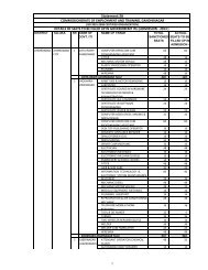
Common Shop Floor Training (4 months approx.)<br />
1. Safety: Safety precautions, first aid and artificial respiration, Elements of fire<br />
Fighting-various types of fire fighting equipments.<br />
2. Manufacturing Techniques/Processes : The shop floor training to be given in as many<br />
manufacturing techniques/processes as possible depending upon the facilities<br />
available in the industry concerned e.g.<br />
i) Soldering, brazing and welding<br />
ii) Wire stripping & forming<br />
iii) Sheet metal working, punching & drilling<br />
iv) Finishing processes-polishing, buffing, spray painting<br />
v) Electrode position of metals on non-conductors<br />
vi) Electroplating processes<br />
vii) P.C.B.single layer-multilayer.
viii) Vacuum impregnation<br />
ix) Bakelite and plastic moulding<br />
3. General Testing<br />
(a) Testing of components such as :<br />
(i)<br />
(ii)<br />
(iii)<br />
(iv)<br />
(v)<br />
(vi)<br />
Resistors<br />
Coils<br />
Capacitors<br />
Ferrite components<br />
Transducers<br />
Crystals<br />
(vii)<br />
(viii)<br />
(ix)<br />
(x)<br />
(xi)<br />
Relays<br />
Micro-switches<br />
Plugs and sockets<br />
Active components<br />
Plated metal parts<br />
(b) Bulk Testing of Electronic Components using Test Rigs & Jigs.<br />
(c) Use of Test Instruments such as :<br />
(i)<br />
(ii)<br />
(iii)<br />
(iv)<br />
(v)<br />
Insulator Tester<br />
Vacuum Tube Tester<br />
Transistor Tester<br />
I.C. tester<br />
Logic circuit Tester<br />
4. Inspection<br />
Step-wise and final inspection procedures and other quality control techniques.<br />
5. Maintenance<br />
5. Transformers & Coils<br />
(a) Wiring of an electronic maintenance/test bench<br />
(b) Modern trouble shooting sequences & techniques for electronic<br />
equipments.<br />
(c) Replacement of defective components in –<br />
(i) Simple electronic circuits on chasis.<br />
(ii) P.C.B. circuits<br />
(iii) Hybrid circuits<br />
(d) Care and replacement of sockets for –<br />
(i) Vacuum tubes<br />
(ii) Transistors<br />
(iii) I.Cs.
(a) Care and maintenance of the following transformers :<br />
(i)<br />
(ii)<br />
(iii)<br />
(iv)<br />
(v)<br />
(vi)<br />
Power<br />
A.F.-Input-Driver-output<br />
I.F.<br />
R.F.<br />
Rewinding of small transformers<br />
Winding of R.F. coils, deflection coils , etc.<br />
MAJOR GROUPS<br />
(At least One Group to be covered during shop-floor training-8 months approx.)<br />
Group – A<br />
Domestic Electronics<br />
Shop Training is assembling, aligning, testing and servicing of any one or more of the<br />
following equipment :<br />
(a) Radio Receiver (Tube, Transistor & Hybrid Versions)<br />
(b) Black and White T.V. Receiver (Tube, Transistor and Hybrid Versions)<br />
(c) F.A. Systems, Stereo Amplifier Systems etc,<br />
(d) Tape Recorder (Cassette and Spool Type).<br />
(e) Colour T.V. Receivers<br />
Group –B<br />
Industrial Electronics<br />
Shop Training in assembling, aligning, testing and servicing of any one of or more of<br />
the following equipment/systems<br />
(a) Speed control<br />
(b) Photo Electric Control<br />
(c) Welding control and Servo control<br />
(d) Process control<br />
Group-C<br />
Medical Electronics<br />
Shop Training in assembling, aligning, testing and servicing of any on or more of the<br />
following medical equipment/systems. :<br />
(a) E.C.G. systems<br />
(b) Recording Systems<br />
(c) Patient Monitor systems<br />
(d) X-Rays system<br />
(e) Other Medical Electronics<br />
Group – D<br />
Professional Electronics
Shop Training in assembling, aligning, testing and servicing of any one or more of the<br />
following equipment :<br />
(a) A.F. Signal generator, pulse generator.<br />
(b) R.F. Signal generator<br />
(c) V.T.V.M. and multimeters<br />
(d) C.R.O.<br />
(e) Power supplies and stabilizers.<br />
(f) Electronic desk calculators<br />
(g) Digital systems<br />
(h) Electronic exchanges.<br />
Group _E<br />
Electronic Components.<br />
Shop Training in manufacture and testing of Electronic materials and components.<br />
SYLLABUS FOR RELATED INSTRUCTIONS :<br />
Related Instruction should be imported to all apprentices during the entire period of<br />
training. The syllabus given for related instruction should be considered as a<br />
guideline.<br />
The syllabus to be taught to the apprentices in related instruction would be under the<br />
following headings :<br />
(1) Trade Theory<br />
(2) Technical Calculations and Estimating<br />
(3) Engineering Drawing<br />
(4) Industrial Development<br />
The contents of the syllabus in the above headings during first two years should be the<br />
same as the contents of the two years training course for he I.T.I. trainees in the trade<br />
of Mechanic (Radio & T.V.) /Mechanic (General Electronic)<br />
THIRD YEAR<br />
1. Trade Theory (3 hours per week or 150 hrs. per year approx.)<br />
(The number of hours to be spent on the different topics in the Trade Theory has<br />
been indicated. The hours indicated are flexible and are only intended as a guide).<br />
(1) Safety at Work<br />
Safety devices and measures in handling electrical and electronic<br />
equipment. Fire fighting equipment.<br />
(2) Revision of the work of previous two years.<br />
(3) Small Motors : Constructional features, principle of operation and<br />
applications of fractional hours power motors and micro motors.<br />
(4) Electro Mechanical/Magnetic Devices & components :
i. Various types of relays and their applications<br />
ii. Micro switches, limit switches and other types of switches and<br />
their applications in electronic systems<br />
iii. Transformers : Input, output, power, driver, EHT & pulse<br />
transformers, their windings and applications.<br />
iv. Plugs, sockets, multipin connectors, PCB connectors, R.F. & A.F.<br />
connectors, tube, transistor and I.C. sockets.<br />
(5) Electronics Devices<br />
Passive Devices.<br />
Various types of resistors, their rating and performance characteristics.<br />
Various type of coils such as A.F., I.F. and I.F. , coils, various types of<br />
capacitors such as electrolytic, paper, mica, ceramic, tantalum, polyester,<br />
styreflex, oil filled etc. their performance ratings and applications.<br />
Ferrites : Ferrite components and their applications.<br />
Transducers : Types of transducers and their application in electric<br />
systems.<br />
Crystals : Types of crystals and their applications.<br />
Insulators : Electrical properties of ceramic, plastic bakelite, mica and<br />
other insulating materials and their applications in electronic components<br />
and systems.<br />
Active Components<br />
Principle of operations and performance characteristics of devices such as<br />
vacuum tubes, gas tubes, photo-tubes, CRT (including picture tubes),semiconductor<br />
diodes (zener, rectifying, detection, tunnel, switching, diodes,<br />
gunn diodes, varactor diode and photo diodes) thermistors, VDRs, silicon<br />
and Germanium transistors, FET’S UJT, DIAC’S, TRIAC’S etc. and<br />
integrated circuits.<br />
Application of the above components in common electronic equipment.<br />
Display devices-Nixie tubes, LEDs, LCDs, etc.<br />
(6) Electronic Modules<br />
Operating principles, testing and maintenance of electronic modules such<br />
as<br />
(i) Rectifier<br />
(ii) Amplifier modules<br />
(iii) Detector modules<br />
(iv) Modulator modules<br />
(v) Oscillator modules<br />
(a) Sine Wave<br />
(b) Square Wave<br />
© Saw Tooth Wave<br />
(vi) Mixer modules<br />
(vii) Differentiating modules<br />
(viii) Integrating modules<br />
(ix) Logic circuit modules<br />
(x) Multivibrator modules
(xi) Multiplexer modules<br />
(xii) Recorder modules<br />
(xiii) Timer modules<br />
(xiv) Voltage regulator modules<br />
(7) System Assembly<br />
General principles of the working and block diagrams of systems such as<br />
(i) Radio<br />
(ii) TV (Black and White )/TV(Colour)<br />
(iii) P.A. systems<br />
(iv) Tape recorders<br />
(v) Slide/Cine projectors<br />
(vi) V.T.V.M.<br />
(vii) C.R.O.<br />
(viii) Signal generators<br />
(ix) Pulse generators<br />
(x) X-Ray equipment<br />
(xi) Electro cardiographs<br />
(xii) Recording systems<br />
(xiii) Speed control DC motors etc.<br />
(xiv) Analytical instruments (Electronic)<br />
(xv) Communication systems.<br />
(8) Testing and Calibrations<br />
Testing procedures for domestic and professional electronic equipments<br />
Calibration standards,.<br />
ISI standards for various electronic equipment<br />
Quality testing of components and systems<br />
(9) Maintenance and Servicing<br />
Trouble shooting techniques, modern techniques etc. proper use of electronic<br />
testing instruments/equipments for servicing electronic systems. Use of test<br />
rigs & jigs, components substitution in handling of P.C.B. circuits and hybrid<br />
circuits etc.<br />
General manufacturing techniques adopted to be studied for the processes such<br />
as :<br />
`<br />
(i) Printed circuit boards-layout, manufacture, etc.<br />
(ii) Soldering techniques, brazing, welding, etc.<br />
(iii) Jointing techniques.<br />
(iv) Electroplating-anodizing, nickel plating, galvanizing etc.<br />
(v) Electro-deposition of metals on non-conductors<br />
(vi) Carpentry work, fret working machines, cabinet making etc.<br />
(vii) Bakelite and plastic moulding<br />
(viii) Sheet metal work-shearing, punching<br />
(ix) Thread cutting-use of taps and dies.<br />
(x) Vacuum impregnating<br />
(xi) Polishing, buffing etc.
II.<br />
Technical Calculation and Estimating<br />
1. Review of mathematics taught in the first two years.<br />
2. Use of Logarithmic tables for all technical calculations.<br />
3. Trigonometry-Use of trigonometric tables, simple problems in basic<br />
trigonometry.<br />
4. Slide Rule-Use in technical calculations.<br />
5. Electronic Desk Calculators : Use in technical calculations.<br />
6. Simple calculations on<br />
(i) Rating, efficiency, etc. of small motors, transformers.<br />
(ii) Rating of resistors.<br />
(iii) Frequency response, amplification, biasing etc, of amplifiers.<br />
(iv) Choice of rectifier, determination of rating etc.<br />
(v) Simple LCR circuits, resonance and oscillators etc.<br />
(vi) Coils, Q.factor, mutual inductance, etc.<br />
7. Estimating the cost of<br />
(i) Domestic electronic equipment<br />
(ii) Professional electronic equipment<br />
(iii) Industrial control equipment<br />
III.<br />
Engineering Drawing<br />
(i) Revision of previous two years work<br />
(ii) Blue print reading<br />
(iii) Advanced circuit diagrams, their reading and drawing<br />
(iv) Code of practice for General Engineering Drawings according to BIS<br />
IS : 696-1960)<br />
(v) Undertaking of basic tool assembly drawings<br />
(vi)_ Free-hand sketching of actual parts of simple electrical and electronic<br />
components.