Trigenflex Ceiling, Wall, Stand Model Dr. Mach
Trigenflex Ceiling, Wall, Stand Model Dr. Mach
Trigenflex Ceiling, Wall, Stand Model Dr. Mach

You also want an ePaper? Increase the reach of your titles
YUMPU automatically turns print PDFs into web optimized ePapers that Google loves.
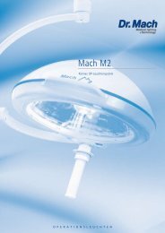
<strong>Trigenflex</strong> <strong>Ceiling</strong>, <strong>Wall</strong>, <strong>Stand</strong> <strong>Model</strong><br />
DIRECTIONS FOR USE<br />
<strong>Trigenflex</strong><br />
<strong>Dr</strong>. <strong>Mach</strong><br />
Lamps and Engineering<br />
Single ceiling with central spring arm,<br />
for room heights up to 2,7m ______________________ Order No. 3051 3031 25<br />
Single ceiling with central spring arm,<br />
for room heights between 2,7m and 3,0m ___________ Order No. 3051 3031 30<br />
<strong>Ceiling</strong> lamps - combinations<br />
<strong>Dr</strong>. <strong>Mach</strong> GmbH u. Co., Flossmannstrasse 28, D-85560 Ebersberg<br />
Tel.: +49 (0)8092 2093 0, Fax +49 (0)8092 2093 50<br />
Internet: www.dr-mach.com, E-mail: info@dr-mach.de<br />
59230002 Edition 02 18.02.2002 / Bak Page 1/24
<strong>Trigenflex</strong> <strong>Ceiling</strong>, <strong>Wall</strong>, <strong>Stand</strong> <strong>Model</strong><br />
List of contents<br />
<strong>Dr</strong>. <strong>Mach</strong><br />
Lamps and Engineering<br />
1. Safety instructions ......................................................................................Page 3<br />
2. Operating the lamp <strong>Trigenflex</strong>.....................................................................Page 4<br />
2.1 Checking the lamp <strong>Trigenflex</strong> with light intensity control.......................Page 4<br />
2.2 ON/OFF switch, light intensity adjustment ............................................Page 6<br />
2.3 Positioning ............................................................................................Page 7<br />
2.4 Light field adjustment (merging of light fields).......................................Page 7<br />
3. Cleaning......................................................................................................Page 8<br />
3.1 Sterilizable handle ................................................................................Page 8<br />
3.2 Lamp head, splinter protection disk ......................................................Page 8<br />
4. Maintenance ...............................................................................................Page 9<br />
4.1 Adjustments at the ceiling/ wall attachment ..........................................Page 9<br />
4.2 Adjustments at the stand ......................................................................Page 10<br />
4.3 Adjustments at the lamp head ..............................................................Page 10<br />
4.4 Changing of spare parts .......................................................................Page 11<br />
4.4.1 Changing the halogen bulbs........................................................Page 11<br />
4.4.2 Changing the fuses .....................................................................Page 12<br />
4.4.3 Changing the filter disk................................................................Page 13<br />
4.4.4 Changing the splinter protection disk ..........................................Page 13<br />
5. Data ............................................................................................................Page 14<br />
5.1 Technical data ......................................................................................Page 14<br />
5.2 Wiring ...................................................................................................Page 15<br />
5.3 Environmental conditions......................................................................Page 16<br />
6. Marking.......................................................................................................Page 16<br />
6.1 Specification of bulb .............................................................................Page 16<br />
6.2 Specification of fuse .............................................................................Page 17<br />
6.3 CE-mark ...............................................................................................Page 17<br />
7. Disposal ......................................................................................................Page 17<br />
8. Spare parts .................................................................................................Page 18<br />
8.1 Design with power supply 230V/120V ..................................................Page 18<br />
8.2 Design with power supply 24V..............................................................Page 19<br />
8.3 Swivel arm – stand model.....................................................................Page 19<br />
8.4 Spare part list .......................................................................................Page 20<br />
59230002 Edition 02 18.02.2002 / Bak Page 2/24
<strong>Trigenflex</strong> <strong>Ceiling</strong>, <strong>Wall</strong>, <strong>Stand</strong> <strong>Model</strong><br />
Dear customer!<br />
<strong>Dr</strong>. <strong>Mach</strong><br />
Lamps and Engineering<br />
Please read the safety instructions and product description carefully before working with<br />
these lamps for the first time.<br />
Please follow the separate mounting instructions for ceiling and wall-mounted lamps, and for<br />
fitting the stand foot and stand tube.<br />
1. Safety instructions<br />
Please pay attention to the directions for use when handling the lamp.<br />
Attention:<br />
This device is not suitable for use in hazardous locations. The lamp is classified<br />
as a Group 1 device according to the MedGV (Medical Ordinance).<br />
Repairs to the lamp and special installation work on the reflector or plug-in socket<br />
should only be carried out by ourselves or a company expressly authorised by ourselves.<br />
The manufacturer is only responsible for the safety of the lamp if repairs and alterations<br />
have been carried out by themselves or a company who can guarantee that the<br />
safety regulations have been observed.<br />
The manufacturer is not liable for personal or material damages if the lamp is misappropriately<br />
or incorrectly operated or misused.<br />
Make sure that the lamp is in perfect working order before use.<br />
59230002 Edition 02 18.02.2002 / Bak Page 3/24
<strong>Trigenflex</strong> <strong>Ceiling</strong>, <strong>Wall</strong>, <strong>Stand</strong> <strong>Model</strong><br />
2. Operating the lamp <strong>Trigenflex</strong><br />
<strong>Dr</strong>. <strong>Mach</strong><br />
Lamps and Engineering<br />
The dielectric filter disk between reflector and splinter protection disk prevents a damaging heating of the<br />
illuminated area.<br />
The lamp may not be used without the dielectric filter disk.<br />
2.1 Checking the lamp <strong>Trigenflex</strong> with electronic light intensity control<br />
• Voltage measurement and setting<br />
Before using the OT-lamps, a voltage measurement and, if necessary, a voltage setting has to be done.<br />
Only in this way a perfect functioning can be ensured.<br />
If the location of the lamp is changed, the voltage measurement and setting must be repeated.<br />
♦ Voltage measurement at the halogen bulbs<br />
Screw<br />
Measuring points 3+4<br />
Measuring points 1+2<br />
♦ Voltage setting at the halogen bulbs<br />
Measuring points 1+2<br />
To measure the voltage proceed as follows:<br />
Mount the lamp to the ceiling or wall attachment.<br />
Switch on the lamp.<br />
In order to make the measurement remove the<br />
cover. Remove the screw in the middle of the cover<br />
and take off the cover.<br />
The measuring points for checking the voltage are<br />
in the same position on all <strong>Trigenflex</strong> lamps.<br />
The measuring points are shown in the figure.<br />
At measuring points 1 + 2 measure the voltage<br />
applied at the halogen bulbs. The lamp is set to<br />
the maximum intensity.<br />
The AC or DC voltage depends on the external<br />
power supply.<br />
Rated voltage 22,8-23,8V.<br />
If the voltage measured is too high or too low, it<br />
must be adjusted at the power supply.<br />
The setting at the transformer is made by reconnecting<br />
the wires on the secondary side.<br />
59230002 Edition 02 18.02.2002 / Bak Page 4/24
<strong>Trigenflex</strong> <strong>Ceiling</strong>, <strong>Wall</strong>, <strong>Stand</strong> <strong>Model</strong><br />
♦ Voltage measurement at the control board<br />
Please check, whether the power supply is supplying AC or DC.<br />
<strong>Dr</strong>. <strong>Mach</strong><br />
Lamps and Engineering<br />
Voltage measurement at DC<br />
Pay attention to the polarisation during the installation.<br />
If the light intensity control does not function as desired, the PLUS- and MINUS-pole at the power<br />
supply have to be changed.<br />
Voltage measurement at AC<br />
For installation at AC proceed as described below:<br />
Measuring points3+4<br />
♦ Voltage setting at the control board<br />
J5<br />
J4<br />
Control board<br />
J4 J5<br />
• Preparation<br />
The lamp is already switched on. Set the lamp to<br />
the lowest light intensity.<br />
• Measurement<br />
Measure the voltage at measuring points 3 + 4. The<br />
voltage must be less than 40V DC.<br />
If this value is exceeded, reset as described below:<br />
Switch the lamp off.<br />
The position of the control board is shown in the<br />
figure.<br />
Adjust the standard setting by changing the jumpers<br />
(see arrow).<br />
Three settings enable you to ideally set your lamp<br />
system (J4 and J5).<br />
J5 J5 J5<br />
J4 J4 J4<br />
I. II. III.<br />
Take off one jumper and put it into position as<br />
shown in figure II. or III.<br />
Switch on the lamp. Set the lamp to the lowest<br />
light intensity.<br />
Repeat the voltage measurement at measuring<br />
points 3 + 4.<br />
If the voltage is less than 40V DC, keep the chosen<br />
setting.<br />
59230002 Edition 02 18.02.2002 / Bak Page 5/24
<strong>Trigenflex</strong> <strong>Ceiling</strong>, <strong>Wall</strong>, <strong>Stand</strong> <strong>Model</strong><br />
If you measure a voltage in excess of 40V DC, switch off the lamp.<br />
Return the first jumper to the initial position.<br />
Take off the second jumper and place it back on one of the two pins.<br />
<strong>Dr</strong>. <strong>Mach</strong><br />
Lamps and Engineering<br />
Switch on the lamp again. Finally repeat the voltage measurement. The voltage is now adjusted.<br />
Close the lamp by replacing the cover.<br />
2.2 ON/OFF switch, light intensity control<br />
A<br />
B<br />
C<br />
1<br />
2<br />
♦ Design for power supply 24V (figure A)<br />
<strong>Ceiling</strong>/ wall model<br />
There are no ON/OFF switches on the lamp.<br />
The customer must provide a two-pole ON/OFF switch.<br />
Remark: In case of <strong>Trigenflex</strong> lamps with power supply<br />
24V, there is no switch for two-step light intensity adjustment.<br />
♦ Power supply for 230V/120V AC<br />
toroid transformer design (figure B)<br />
<strong>Ceiling</strong>/ wall model<br />
The rocker switch 1 switches the lamp ON and OFF.<br />
The rocker switch 2 adjusts the light intensity from<br />
STRONG to WEAK.<br />
♦ <strong>Stand</strong> model (figure C)<br />
3<br />
The ON/OFF switch is positioned in the<br />
counter balance 3.<br />
There are no ON/OFF switches on the<br />
lamp housing.<br />
59230002 Edition 02 18.02.2002 / Bak Page 6/24
<strong>Trigenflex</strong> <strong>Ceiling</strong>, <strong>Wall</strong>, <strong>Stand</strong> <strong>Model</strong><br />
5<br />
6<br />
3<br />
7 3 4<br />
3<br />
4<br />
2.3 Positioning<br />
♦ <strong>Ceiling</strong>/ wall model<br />
<strong>Dr</strong>. <strong>Mach</strong><br />
Lamps and Engineering<br />
For positioning use sterilizable handle 3.<br />
Handle rail 4 is used for adjusting the lights from the<br />
outside.<br />
The cardan bow 5 is used for convenient, fully cardanic<br />
adjustment of the lamp.<br />
The cardan bow is delivered separately.<br />
The coupling for the bow of the lamp body is fitted<br />
with a needle bearing. The inner ring 6 of this needle<br />
bearing has already been pushed onto the axis<br />
of lamp body bow.<br />
♦ <strong>Stand</strong> model<br />
For positioning use sterilizable handle 3.<br />
Handle rail 4 is used for adjusting the lamps from<br />
the outside.<br />
For stand models, the bow of the lamp body is directly<br />
coupled to the bracket 7. Neither part 5 or 6<br />
are used in this case.<br />
2.4 Light field adjustment<br />
(merging of light fields)<br />
The <strong>Trigenflex</strong> lamps are equipped with the function<br />
of lightfield realignment.<br />
That means, you can merge the separated light<br />
fields to one spot as shown in the figure.<br />
To activate the merging of light fields, turn the sterilizable<br />
handle 3.<br />
59230002 Edition 02 18.02.2002 / Bak Page 7/24
<strong>Trigenflex</strong> <strong>Ceiling</strong>, <strong>Wall</strong>, <strong>Stand</strong> <strong>Model</strong><br />
Cleaning / disinfection and sterilisation<br />
3. Cleaning<br />
V<br />
8<br />
3.1 Sterilisable handle<br />
<strong>Dr</strong>. <strong>Mach</strong><br />
Lamps and Engineering<br />
At delivery the lamp is equipped with the handle<br />
sleeve 1. The handle sleeve is removable and sterilisable.<br />
Before using the first time and before every<br />
use the handle sleeve must be cleaned, disinfected<br />
and sterilised.<br />
The handle sleeve must be removed for sterilisation:<br />
• To remove press the lock V and pull off the<br />
sterilisable handle sleeve 1 while keeping the<br />
lock pressed.<br />
• To attach, push on and slightly twist the handle<br />
until the lock V engages securely.<br />
Handles often become unsterile during an OP;<br />
therefore always keep additional handles available<br />
for exchange.<br />
Basics<br />
Efficient cleaning / disinfection is an essential requirement for effective sterilisation of the handle.<br />
Within the scope of responsibility for the sterility of the products it should be noted that only sufficiently<br />
validated equipment and product specific processes are used for cleaning / disinfection and that the validated<br />
parameters are complied with in every cycle.<br />
In addition, the hospital / clinic hygiene regulations must be observed.<br />
Cleaning / disinfection<br />
Cleaning and disinfection must be carried out immediately after use.<br />
A mechanised process (disinfector) should be used for cleaning / disinfection. The efficiency of the process<br />
used must be recognised and validated in principle (e.g. listed under disinfectants and disinfection<br />
procedures tested and recognised by Robert-Koch-Institute / DGHM).<br />
When using other procedures (e.g. a manual procedure), proof and process efficiency in principle must<br />
be provided within the scope of validation.<br />
Proof in principle of the suitability of the handles for efficient cleaning / disinfection was provided using a<br />
cyclic cleaning system (Netsch-Bellmed T-600-IUDT/AN, programme 2 for small parts; code B).<br />
It is not allowed to use agents / disinfectants, which contain the following substances, as these may<br />
cause changes in the material:<br />
- High-concentration organic and inorganic acids<br />
- Chlorinated hydrocarbons<br />
- 2-ethoxyethanol<br />
59230002 Edition 02 18.02.2002 / Bak Page 8/24
<strong>Trigenflex</strong> <strong>Ceiling</strong>, <strong>Wall</strong>, <strong>Stand</strong> <strong>Model</strong><br />
When cleaning / disinfecting, the following procedures must be followed:<br />
<strong>Dr</strong>. <strong>Mach</strong><br />
Lamps and Engineering<br />
Process Time (sec.)<br />
Zone 1 Pre-rinse, external, cold, 10 – 15°C 45<br />
Washing, acidic, external 35°C 120<br />
<strong>Dr</strong>aining time 10<br />
Re-rinse, external approx. 80°C *10<br />
<strong>Dr</strong>aining time *15<br />
Re-rinse, external approx. 80°C *15<br />
<strong>Dr</strong>aining time 15<br />
Zone 2 Washing, alkaline, external, 93°C 135<br />
<strong>Dr</strong>aining time 10<br />
Re-rinse, external, acidic, 90°C 10<br />
<strong>Dr</strong>aining time 15<br />
Re-rinse, external 90°C 15<br />
<strong>Dr</strong>aining time 15<br />
Zone 3 <strong>Dr</strong>ying, external 100 – 120°C 200<br />
Zone 4 <strong>Dr</strong>ying, external 100 – 120°C 200<br />
Door open / close & transport 60<br />
(sluice discharge)<br />
Cycle time overall ca. 290<br />
≈ 5 minutes<br />
* When occupying the disinfection zone (washing zone 2), the re-rinse and draining times will depend<br />
on the respective objects being washed therein!<br />
Sterilisation<br />
Only previously cleaned and disinfected handles may be sterilised.<br />
The handles are placed in a suitable sterilisation pack (one-way sterilisation pack, e.g. foil / paper sterilisation<br />
bags, single or double pack) in accordance with DIN EN 868 / ISO 11607 for steam sterilisation<br />
and then sterilised.<br />
Use only the sterilisation procedure listed below for sterilisation. Other sterilisation procedures (e.g. ethylene<br />
oxide, formaldehyde and low-temperature plasma sterilisation) are not permissible.<br />
Steam sterilisation procedure<br />
Validated in accordance with DIN EN 554/ISO 11134<br />
Maximum sterilisation temperature 134°C<br />
Proof in principle of the handles’ suitability for effective sterilisation was provided using a fractional vacuum<br />
process (Euroselectomat 666 by MMM Münchner Medizin Mechanik GmbH, sterilising temperature<br />
134°C, holding time 7 min.)<br />
Inspection / durability<br />
The handles should be inspected for damage and changed before re-use, if required.<br />
The handles may be cleaned / disinfected, sterilised and re-used for a maximum of 1000 times. If the<br />
handles are re-used more than 1000 times, then this will be the responsibility of the hospital / clinic.<br />
59230002 Edition 02 18.02.2002 / Bak Page 9/24
<strong>Trigenflex</strong> <strong>Ceiling</strong>, <strong>Wall</strong>, <strong>Stand</strong> <strong>Model</strong><br />
2<br />
3<br />
Alc. ≤ 20 %<br />
<strong>Dr</strong>. <strong>Mach</strong><br />
Lamps and Engineering<br />
3.2 Lamp head, splinter protection disk<br />
The lamp head 2 has a high-quality surface, which<br />
can be cleaned with conventional cleaning agents.<br />
The splinter protection disks 3 are made of a highquality<br />
plastic. Pay attention to the following during<br />
cleaning:<br />
• Wipe the splinter protection disks 3 always with<br />
a wet cloth. Do not wipe dry!<br />
• Only use disinfectant with less than 20% alcohol.<br />
Wipe the splinter protection disks 3 after cleaning<br />
with an antistatic, non-fluffy cloth.<br />
59230002 Edition 02 18.02.2002 / Bak Page 10/24
<strong>Trigenflex</strong> <strong>Ceiling</strong>, <strong>Wall</strong>, <strong>Stand</strong> <strong>Model</strong><br />
4. Maintenance<br />
<strong>Dr</strong>. <strong>Mach</strong><br />
Lamps and Engineering<br />
The lamp has been designed and built so that regular maintenance intervals are not necessary.<br />
In order to keep the system easy running throughout its life span, we recommend, that the hinges should<br />
be greased once a year with an acid-free grease.<br />
+<br />
X<br />
Width 5<br />
Hole 1<br />
1<br />
2<br />
10°<br />
-<br />
4.1 Adjustments at the ceiling /<br />
wall attachment<br />
♦ Adjusting the spring arm<br />
Note:<br />
Maximum additional load at spring arms: Spring<br />
arms are equipped with different springs to<br />
compensate the lamp / device weight.<br />
To adjust the spring force make sure that the spring<br />
arm with the lamp / device can come to rest in any<br />
desired position.<br />
• A hole 1 is located at the position marked by<br />
detail X.<br />
• Position the spring arm 2 with the lamp / device<br />
approximately 10° above horizontal.<br />
• Insert Allan key (width 5, included in the scope<br />
of supply) into the hole 1.<br />
If the spring arm drops, the spring force is too low:<br />
- Rotate the adjustment screw to the left (counter<br />
clockwise) in the + direction.<br />
If the spring arm rises, the spring force is too high:<br />
- Rotate the adjustment screw to the right<br />
(clockwise) in the - direction.<br />
If the spring arm with the lamp / device cannot<br />
come to rest in any desired position after the<br />
spring force has been adjusted, the springs<br />
must be replaced by a service technician.<br />
59230002 Edition 02 18.02.2002 / Bak Page 11/24
<strong>Trigenflex</strong> <strong>Ceiling</strong>, <strong>Wall</strong>, <strong>Stand</strong> <strong>Model</strong><br />
5<br />
1<br />
9<br />
6<br />
2<br />
8<br />
7<br />
4.2 Adjustments at the stand<br />
♦ Swivel arm<br />
<strong>Dr</strong>. <strong>Mach</strong><br />
Lamps and Engineering<br />
You can fasten the move of the swivel arm 1 by<br />
adjusting lever 2.<br />
4.3 Adjustments at the lamp head<br />
♦ Adjusting the lamp bow<br />
In case you notice that the lamp no longer remains<br />
at its set position, it may be necessary to adjust the<br />
lamp bow 9.<br />
For adjusting the lamp bow proceed as follows:<br />
• Turn off the lamp.<br />
• Unscrew the raised countersunk screw 5 using<br />
a cross screw driver.<br />
• Remove the upper part of the lamp housing.<br />
• Screw the nuts 6 on both sides a little tighter<br />
using an open-ended or ring wrench SW 14, or<br />
loosen these nuts while at the same time holding<br />
the screw slot 7 in each case with a screw<br />
driver.<br />
• Once the adjustment has been made, place<br />
seal 8 correctly on the housing lower part and<br />
position the upper part of the lamp housing<br />
slightly diagonally from one side, so that the<br />
seal lies cleanly around the circumference.<br />
• Using a round object (drawing pin or small<br />
screw driver) lift the seal and lower the lamp<br />
housing upper part, until it sits evenly around<br />
the whole circumference.<br />
• Tighten with the raised countersunk screw 5.<br />
59230002 Edition 02 18.02.2002 / Bak Page 12/24
<strong>Trigenflex</strong> <strong>Ceiling</strong>, <strong>Wall</strong>, <strong>Stand</strong> <strong>Model</strong><br />
1<br />
1<br />
2<br />
3<br />
4<br />
4.4 Changing of spare parts<br />
<strong>Dr</strong>. <strong>Mach</strong><br />
Lamps and Engineering<br />
4.4.1 Changing the halogen bulbs<br />
<strong>Dr</strong>. <strong>Mach</strong> uses special halogen bulbs as illuminants.<br />
Only original <strong>Dr</strong>. <strong>Mach</strong> replacement bulbs may<br />
be used.<br />
The use of other bulbs can lead to a considerable<br />
reduction of the light power and increase in the<br />
thermal load.<br />
To change the halogen bulbs proceed as follows:<br />
• Turn off the lamp.<br />
• Rotate the three quick-release fasteners 1 half<br />
a turn anticlockwise so that the corresponding<br />
disk bearer can be removed from the bottom<br />
part of the lamp housing.<br />
• Press outwards security clip 2 and turn shade<br />
holder 3 down.<br />
• Carefully remove the halogen bulb 4 (22,8-<br />
24V/50W) from its socket, change and replace.<br />
• Replace shadeholder and the disk bearer onto<br />
the bottom part of the lamp housing and rotate<br />
the quick-release fasteners 1 clockwise.<br />
Do not touch the halogen bulb with naked hands.<br />
Remove stains with a clean cloth and alcohol since<br />
otherwise these can burn into the glass and lead to<br />
early failures.<br />
Remark:<br />
The halogen bulbs have a service life of approx.<br />
1000 hours without any deterioration in their<br />
luminosity.<br />
If after approx. six months of average use of eight<br />
hours daily one of the halogen light bulbs should<br />
fail, we recommend, that the whole set should be<br />
replaced.<br />
59230002 Edition 02 18.02.2002 / Bak Page 13/24
<strong>Trigenflex</strong> <strong>Ceiling</strong>, <strong>Wall</strong>, <strong>Stand</strong> <strong>Model</strong><br />
1<br />
2<br />
1<br />
1<br />
4.4.2 Changing the fuses<br />
<strong>Dr</strong>. <strong>Mach</strong><br />
Lamps and Engineering<br />
♦ <strong>Ceiling</strong>/ wall/ stand model<br />
Power supply with 24V AC/DC<br />
In case of designs for power supply with 24V<br />
AC/DC the necessary fuses are provided by the<br />
customer.<br />
Pay attention to the instructions from the local<br />
installer.<br />
♦ <strong>Ceiling</strong>/ wall model<br />
Power supply with 230V/120V AC<br />
built in toroid transformer<br />
The fuses in the lamp housing (toroid transformer<br />
design) prevent the transformer burning through in<br />
the event of a short-circuit.<br />
Visible type 5x20/2,00A/250V/T for 230 V<br />
Visible type 5x20/4,00A/250V/T for 120 V<br />
If the bulb is no longer on, check the bulb first, then<br />
the fuses.<br />
To change the fuses proceed as follows:<br />
• Turn off the lamp.<br />
• Turn the black fuse holder (1) ¼ of a rotation<br />
anticlockwise with a screw driver.<br />
• Change the fuses.<br />
• Insert the fuse holder under slight pressure and<br />
rotate in a clockwise direction (bayonet catch).<br />
♦ <strong>Stand</strong> model<br />
Power supply with 230V AC<br />
The fuses are positioned in the counter balance 2<br />
as shown in the figure.<br />
Visible type 5x20/2,00A/250V/T for 230 V<br />
To change the fuses proceed as follows:<br />
• Turn off the lamp.<br />
• Turn the black fuse holder (1) ¼ of a rotation<br />
anticlockwise with a screw driver.<br />
• Change the fuses.<br />
• Insert the fuse holder under slight pressure and<br />
rotate in a clockwise direction (bayonet catch).<br />
59230002 Edition 02 18.02.2002 / Bak Page 14/24
<strong>Trigenflex</strong> <strong>Ceiling</strong>, <strong>Wall</strong>, <strong>Stand</strong> <strong>Model</strong><br />
1<br />
4<br />
4<br />
2<br />
3<br />
5<br />
6<br />
7<br />
4.4.3 Changing the filter disk<br />
<strong>Dr</strong>. <strong>Mach</strong><br />
Lamps and Engineering<br />
The dielectric filter disk between reflector and splinter<br />
protection disk prevents a damaging heating of<br />
the illuminated area.<br />
The lamp may not be used without this filter.<br />
To change the filter disk proceed as follows:<br />
• Turn off the lamp.<br />
• Rotate the three quick-release fasteners 1 half<br />
a turn anticlockwise so that the corresponding<br />
disk bearer can be removed from the bottom<br />
part of the lamp housing.<br />
• Slightly loosen nuts 2, carefully bend the retaining<br />
springs 3 apart and change filter disk 4.<br />
Only use filter disks which have been cleaned<br />
accordingly.<br />
4.4.4 Changing the splinter protection<br />
disk<br />
In case the light quality is getting worse because of<br />
a dull splinter protection disk, it may be necessary<br />
to change the disk.<br />
To change the splinter protection disk proceed as<br />
follows:<br />
• Turn off the lamp.<br />
• Rotate the quick-release fasteners 1 half of a<br />
turn anticlockwise so that the corresponding disk<br />
bearer can be removed from the bottom part of<br />
the lamp housing.<br />
• Remove filter disk 4 as described at 4.4.3.<br />
• Loosen three nuts 2 M3, remove retaining spring<br />
3 and retaining ring 5.<br />
• Change splinter protection disk 6 and lay stay<br />
tube 7, retaining ring and retaining spring in the<br />
correct order on the disk bearer according to the<br />
illustration.<br />
• Place nuts 2 onto the threaded bolts according<br />
to the illustration and tighten.<br />
• Carefully bend the retaining springs 3 apart and<br />
replace filter disk.<br />
Only use filter disks which have been cleaned<br />
accordingly.<br />
• Replace disk bearer and fasten by turning the<br />
three quick-release fasteners 1.<br />
59230002 Edition 02 18.02.2002 / Bak Page 15/24
<strong>Trigenflex</strong> <strong>Ceiling</strong>, <strong>Wall</strong>, <strong>Stand</strong> <strong>Model</strong><br />
5.1 Technical data<br />
5. Data<br />
Power supply with 24 Volt<br />
Power supply with 230 Volt<br />
Power supply with 120 Volt<br />
alternating current<br />
rated voltage<br />
rated current<br />
frequency Hertz<br />
fuse<br />
class of protection<br />
alternating current<br />
primary side<br />
secondary side<br />
frequency Hertz<br />
fuse<br />
class of protection<br />
alternating current<br />
primary side<br />
secondary side<br />
frequency Hertz<br />
fuse<br />
class of protection<br />
<strong>Dr</strong>. <strong>Mach</strong><br />
Lamps and Engineering<br />
59230002 Edition 02 18.02.2002 / Bak Page 16/24
<strong>Trigenflex</strong> <strong>Ceiling</strong>, <strong>Wall</strong>, <strong>Stand</strong> <strong>Model</strong><br />
5.2 Wiring<br />
N<br />
22,8/24V<br />
L 0V<br />
1 – two-step switch, depending on design<br />
N<br />
Power supply with 24 Volt<br />
Power supply with 230 Volt<br />
1<br />
250V<br />
230V<br />
L 0V<br />
1 – two-step switch, depending on design<br />
23,5V<br />
Power supply with 120 Volt<br />
1<br />
127V<br />
110V<br />
23,5V<br />
<strong>Dr</strong>. <strong>Mach</strong><br />
Lamps and Engineering<br />
59230002 Edition 02 18.02.2002 / Bak Page 17/24
<strong>Trigenflex</strong> <strong>Ceiling</strong>, <strong>Wall</strong>, <strong>Stand</strong> <strong>Model</strong><br />
5.3 Environmental conditions<br />
Operation<br />
Min. Max.<br />
<strong>Dr</strong>. <strong>Mach</strong><br />
Lamps and Engineering<br />
Temperature +10°C +40°C<br />
Relative atmospheric humidity 30% 75%<br />
Air pressure 700 hPa 1060 hPa<br />
Transport / Storage<br />
Min. Max.<br />
Temperature -10°C +50°C<br />
Relative atmospheric humidity 20% 90%<br />
Air pressure 700 hPa 1060 hPa<br />
6.1 Specification of bulb<br />
6. Marking<br />
Protective conductor<br />
ON/OFF switch<br />
Voltage, power<br />
Socket<br />
Mode of operation<br />
59230002 Edition 02 18.02.2002 / Bak Page 18/24
<strong>Trigenflex</strong> <strong>Ceiling</strong>, <strong>Wall</strong>, <strong>Stand</strong> <strong>Model</strong><br />
6.2 Specification of fuse<br />
The lamps do not have fuses in the lamp housing.<br />
6.3 CE-mark<br />
Power supply with 24 Volt<br />
Power supply with 230 Volt<br />
Power supply with 120 Volt<br />
Visible fuse 5x20<br />
Delay action 2,00A<br />
Visible fuse 5x20<br />
Delay action 4,00A<br />
<strong>Dr</strong>. <strong>Mach</strong><br />
Lamps and Engineering<br />
The products <strong>Trigenflex</strong> comply to the standards 93/42/EEC for medical products of the<br />
European Community’s Council.<br />
7. Disposal<br />
The OT-lamp <strong>Trigenflex</strong> does not contain any danger goods.<br />
The components of the OT-lamp should be properly disposed at the end of its shelf life.<br />
Make sure, that the materials are separated accordingly.<br />
For disposal proceed as follows:<br />
• PC-boards should be submitted to an appropriate recycling.<br />
• The rest of the components should be disposed according to the contained materials.<br />
59230002 Edition 02 18.02.2002 / Bak Page 19/24
<strong>Trigenflex</strong> <strong>Ceiling</strong>, <strong>Wall</strong>, <strong>Stand</strong> <strong>Model</strong><br />
8. Spare parts<br />
<strong>Dr</strong>. <strong>Mach</strong><br />
Lamps and Engineering<br />
8.1 Power supply with 230/120 Volt – built in transformer (ceiling-/ wall model)<br />
59230002 Edition 02 18.02.2002 / Bak Page 20/24
<strong>Trigenflex</strong> <strong>Ceiling</strong>, <strong>Wall</strong>, <strong>Stand</strong> <strong>Model</strong><br />
8.2 Power supply with 24 Volt (ceiling-/ wall-/ stand model)<br />
<strong>Dr</strong>. <strong>Mach</strong><br />
Lamps and Engineering<br />
The lamp does not have a built in transformer, fuses, ON/OFF switch and change-over switch.<br />
For spare parts see point 8.1, except the parts mentioned above.<br />
8.3 Swivel arm (stand model)<br />
53<br />
54<br />
59<br />
55<br />
65<br />
56<br />
60<br />
57<br />
61<br />
62,63,64<br />
33,34<br />
59230002 Edition 02 18.02.2002 / Bak Page 21/24<br />
36<br />
58<br />
41
<strong>Trigenflex</strong> <strong>Ceiling</strong>, <strong>Wall</strong>, <strong>Stand</strong> <strong>Model</strong><br />
8.3 Spare part list<br />
<strong>Dr</strong>. <strong>Mach</strong><br />
Lamps and Engineering<br />
Item Qty. Name EDVNO Remark<br />
01<br />
02<br />
1 Lamp bow standard, complete 23100002 alternate<br />
03 2 Sliding contact – pin 07102001 1x in 1<br />
and in 25 or 26<br />
04 2 Bolt 22080203<br />
05 2 Corrugated washer 65542002<br />
06 2 Pressure washer 07011204<br />
07 2 Hexagonal nut M10x1 DIN 439 67900001<br />
08 1 Sterilisable handle sleeve 21150002<br />
09<br />
10<br />
1 Handle coupling 23052001<br />
11 1 Seal 23000201<br />
12 1 Housing lower part for toroid transformer 23012007 230V/120V<br />
13 1 Housing lower part for external transformer 23012008 24V<br />
14<br />
15<br />
2 Bolt, complete 23082202<br />
16 1 Housing upper part 23011201<br />
17 1 Raised countersunk screw M4x12 DIN 966 65112007<br />
18 1 Washer 22080206<br />
19<br />
20<br />
3 Reflector unit, complete 23060001<br />
21 3 Reflector 10060213<br />
22 3 Flange 74011003<br />
23 3 Cooling body 23060214<br />
24 1 Handle bow, complete 23040001<br />
25<br />
26<br />
1 Cardan bow, complete 23110001<br />
27 1 Inner ring for needle bearing in part 25 23110202<br />
28 1 Semi-circular spring 23110203<br />
29 1 Locking screw for semi-circular spring 65112002<br />
30 3 Socket 67320005<br />
31 3 Halogen bulb 22,8-24V/50W 67100201<br />
32 3 Tracer pin 23060207<br />
33 1 Change-over STRONG/WEAK 67340001 230V/120V<br />
34<br />
35<br />
1 Two-pole illuminated ON/OFF switch 67340002 230V/120V<br />
36 2 Fuse holder 67370001 230V/120V,<br />
stand model<br />
37 2 Visible fuse 5x20 2,00A/250V/t 67370005 230V<br />
38 2 Visible fuse 5x20 4,00A/250V/t 67370007 120V<br />
39 1 Toroid transformer<br />
67010106 230V<br />
150VA/prim.230V AC /sec.22/24V AC<br />
RFT BV381187<br />
40 1 Toroid transformer<br />
67010110 120V<br />
150VA/prim.120V AC /sec.22/24V AC<br />
41 1 Toroid transformer 150VA 67010108 Swivel arm<br />
42 1 Central axle, complete 23050001<br />
43<br />
59230002 Edition 02 18.02.2002 / Bak Page 22/24
<strong>Trigenflex</strong> <strong>Ceiling</strong>, <strong>Wall</strong>, <strong>Stand</strong> <strong>Model</strong><br />
<strong>Dr</strong>. <strong>Mach</strong><br />
Lamps and Engineering<br />
Item Qty. Name EDVNO Remark<br />
44 3 Disk bearer, complete 23160001<br />
45 3 Disk bearer ring with quick-release fastener 23161001<br />
46 3 Tubular rivet 65702003<br />
47 3 Splinter protection disk 23200201<br />
48 3 Dielectric filter disk 23250202<br />
49 3 Retaining ring 23160205<br />
50 9 Retaining spring 23160202<br />
51<br />
52 9 Nut M3 DIN 934 65332002<br />
53 1 Raised head screw DIN7985 HM4x10 -4,8Ni 65152010<br />
54 2 Lock washer A4,3 DIN6797 -Zn 65582004<br />
55 1 Brake ring 07100202<br />
56 1 Semi-circular spring 74011001<br />
57 1 Countersunk screw DIN966 HM3x12 -4,8Zn 65112004<br />
58 1 Housing 53237210<br />
59 1 Sliding sleeve for semi-circular spring 53070208<br />
60 1 Sliding contact – receptacle 67330001<br />
61 1 Sliding contact – pin 67330002<br />
62 1 Washer A8,4 DIN125 -Zn 65512008<br />
63 2 Brake disk 53237212<br />
64 1 Adjusting lever 74503002<br />
65 4 Thread pin DIN551 M4x4 14H 65212002<br />
66 1 Acrylic glass box for transformer 300VA 67610101 Not shown<br />
59230002 Edition 02 18.02.2002 / Bak Page 23/24
<strong>Trigenflex</strong> <strong>Ceiling</strong>, <strong>Wall</strong>, <strong>Stand</strong> <strong>Model</strong><br />
<strong>Dr</strong>. <strong>Mach</strong><br />
Lamps and Engineering<br />
59230002 Edition 02 18.02.2002 / Bak Page 24/24