Software Operational Manual for ACS306 - Leadshine
Software Operational Manual for ACS306 - Leadshine
Software Operational Manual for ACS306 - Leadshine

Create successful ePaper yourself
Turn your PDF publications into a flip-book with our unique Google optimized e-Paper software.
<strong>Software</strong> <strong>Operational</strong> <strong>Manual</strong><br />
<strong>for</strong> <strong>ACS306</strong><br />
www.leadshine.com<br />
SM‐<strong>ACS306</strong>‐R20110826
ii<br />
<strong>Leadshine</strong> reserves the right to make changes without further notice to any products<br />
herein to improve reliability, function or design. <strong>Leadshine</strong> does not assume any<br />
liability arising out of the application or use of any product or circuit described<br />
herein; neither does it convey any license under its patent rights of others.<br />
<strong>Leadshine</strong>’s general policy does not recommend the use of its products in life<br />
support or aircraft applications wherein a failure or malfunction of the product may<br />
directly threaten life or injury. According to <strong>Leadshine</strong>’s terms and conditions of<br />
sales, the user of <strong>Leadshine</strong>’s products in life support or aircraft applications<br />
assumes all risks of such use and indemnifies <strong>Leadshine</strong> against all damages.<br />
©2011 by <strong>Leadshine</strong> Technology, All Rights Reserved<br />
Change Log<br />
Revision Date Changes Version<br />
2011-8-26 Original Create SM-<strong>ACS306</strong>-R20110826<br />
SM‐<strong>ACS306</strong>‐R20110826
iii<br />
Table of Contents<br />
Introduction..................................................................................................................................................................... 1<br />
Workspace ............................................................................................................................................................... 1<br />
Menus and Toolbar.......................................................................................................................................... 1<br />
Using the <strong>Software</strong> .................................................................................................................................................. 3<br />
Opening a file .................................................................................................................................................. 3<br />
Save a file........................................................................................................................................................ 3<br />
Save as a file.................................................................................................................................................... 3<br />
Close................................................................................................................................................................ 3<br />
Connecting Drive ............................................................................................................................................ 3<br />
Property Window............................................................................................................................................. 4<br />
Current Loop Tuning Window......................................................................................................................... 6<br />
Position Loop Tuning Window........................................................................................................................ 7<br />
Scope ............................................................................................................................................................. 11<br />
Error Log Window......................................................................................................................................... 12<br />
Configuring the Drive ................................................................................................................................................... 13<br />
Current Loop Tuning............................................................................................................................................. 13<br />
Tuning the 1 st Position Loop Parameters............................................................................................................... 19<br />
Tuning the 2 nd Position Loop Parameters.............................................................................................................. 26<br />
Contact Us..................................................................................................................................................................... 32<br />
SM‐<strong>ACS306</strong>‐R20110826
<strong>Software</strong> <strong>Operational</strong> <strong>Manual</strong> <strong>for</strong> <strong>ACS306</strong><br />
Introduction<br />
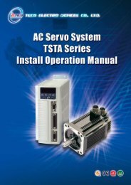
The ProTuner <strong>for</strong> <strong>ACS306</strong> is a software tool designed to configure and tune the <strong>Leadshine</strong> digital servo drive <strong>ACS306</strong>. The user can<br />
tune the current loop and adjust the position loop parameters in this software.<br />
Workspace<br />
Menu<br />
Toolbar<br />
PID Tuning<br />
Window<br />
Menus and Toolbar<br />
Menus and toolbars are at the top of the workspace. You can click menu bar to view the pull-down menu. The toolbar below the menu<br />
offers the most frequency used commands.<br />
SW‐<strong>ACS306</strong>‐R20110826<br />
1
<strong>Software</strong> <strong>Operational</strong> <strong>Manual</strong> <strong>for</strong> <strong>ACS306</strong><br />
Menu Pull Down Toolbar Function Short cut<br />
File -> Open Open a file Ctrl + O<br />
Save Save a file Ctrl + S<br />
Save As - Save as a file -<br />
Close - Close the current file -<br />
Exit - Exit from the software Ctrl + X<br />
Drive -> Connect - Connect to drive Ctrl + N<br />
Properties<br />
Set drive properties like I/O logic,<br />
motor parameters.<br />
-<br />
Current Loop<br />
Set current loop parameters Kp and Ki<br />
and test.<br />
-<br />
Position Loop<br />
Set position loop PID parameters and<br />
test.<br />
-<br />
Download to Drive Download all data to drive -<br />
Reset Drive Restore factory setting -<br />
Open the scope and check the<br />
Tools-><br />
Scope<br />
measured current, position following<br />
-<br />
error and motor velocity.<br />
Error Log Check the error log. -<br />
Help-> User <strong>Manual</strong> on Web Hardware manual -<br />
<strong>Software</strong> <strong>Manual</strong> on Web<br />
<strong>Software</strong> manual<br />
About <strong>Leadshine</strong> ProTuner <strong>Software</strong> in<strong>for</strong>mation -<br />
SW‐<strong>ACS306</strong>‐R20110826<br />
2
<strong>Software</strong> <strong>Operational</strong> <strong>Manual</strong> <strong>for</strong> <strong>ACS306</strong><br />
Using the <strong>Software</strong><br />
Opening a file<br />
If you want to reload the configuration data from a file in the PC, click on the File->Open. The parameters in the software’s workspace<br />
will be updated. The file name will appear on the right of the tile bar.<br />
File Name<br />
Save a file<br />
Click Drive->Save to save the data of current workspace to the opened file. If there is no a file opened, the Save dialog box appears and<br />
you can type in the file name.<br />
Save as a file<br />
Click Drive->Save As to save the data in current workspace to a file and rename it.<br />
Close<br />
Click Drive->Close to close the current file.<br />
Connecting Drive<br />
Connect to Drive window appears when you open the software. You can open it by clicking Drive->Connect any time. Select the right<br />
serial port and click on the Open button. The software will try to connect to the drive and read the settings. It may take several minutes.<br />
Please wait.<br />
SW‐<strong>ACS306</strong>‐R20110826<br />
3
<strong>Software</strong> <strong>Operational</strong> <strong>Manual</strong> <strong>for</strong> <strong>ACS306</strong><br />
!<br />
Notice<br />
Be<strong>for</strong>e clicking on the Open button, please make sure:<br />
1) The RS232 cable .has been connected between the drive and the PC’s serial port.<br />
2) The drive has been powered on and the green LED is turned on.<br />
The motor is unnecessary connecting to the drive if you just want to change the parameters but not tuning.<br />
!<br />
Caution<br />
Do not connect or disconnect serial cable when the drive is powered on. The drive’s communication circuit may be<br />
damaged.<br />
Property Window<br />
Click Drive->Properties to open the Properties window. The user can set the command’s active edge, direction logic, active level of the<br />
Enable and Alarm signal, position following error, electronic gear and motor pole pairs according the motor and application.<br />
!<br />
Notice<br />
The Motor Pole Pairs is very important parameter. .It is 2 <strong>for</strong> <strong>Leadshine</strong>’s BLM series motor and 4 <strong>for</strong> <strong>Leadshine</strong>’s ACM<br />
series motor.<br />
SW‐<strong>ACS306</strong>‐R20110826<br />
4
<strong>Software</strong> <strong>Operational</strong> <strong>Manual</strong> <strong>for</strong> <strong>ACS306</strong><br />
Item Description Range<br />
Active Edge Setting the triggered edge of pulse command signal. Up-rising / Falling<br />
Setting Default motor rotate direction.<br />
Direction<br />
Note: The default direction is also related to motor coil<br />
connections.<br />
Positive / Negative<br />
Enable Signal Setting active level of Enable signal. High Level/ Low Level<br />
Alarm Signal Setting active level of Enable signal. High / Low<br />
Encoder Resolution <strong>for</strong> the Internal Pulse Generator.<br />
Encoder Resolution<br />
Note: This parameter is only used <strong>for</strong> the Internal Pulse<br />
Generator. It is 4 times of the encoder lines.<br />
400 – 60000<br />
Position Following Error Limit<br />
The limit of the difference between commanded position and<br />
the actual measured position. When position following error<br />
exceeds the Position Following Error Limit in the drive, the<br />
following error protection will be activated.<br />
0 – 65535<br />
Electronic Gear<br />
This parameter includes numerator and denominator. You can<br />
scale the pulse frequency and calculate the motor speed as<br />
follows:<br />
( Pulse Input Frequence)<br />
60 Numerator<br />
RPM <br />
<br />
Deno min ator<br />
( Encoder Re solution)<br />
4<br />
1/255 – 512/1<br />
Motor Pole Paris Motor poles divided by 2. Please refer to motor datasheet. 1 – 20<br />
SW‐<strong>ACS306</strong>‐R20110826<br />
5
<strong>Software</strong> <strong>Operational</strong> <strong>Manual</strong> <strong>for</strong> <strong>ACS306</strong><br />
Current Loop Tuning Window<br />
Red Curve:<br />
Target Current of Step Test<br />
Green Curve:<br />
Actual Current of Step Test<br />
Click Drive->Current Loop to open the current loop tuning window. It is used to configure current loop parameters according to different<br />
motor. In the tuning window, the user can adjust the proportional gain, integral gain and test Current.<br />
Item Description Range<br />
Proportional Gain<br />
Increase this parameter to make current rise fast. Proportional Gain<br />
determines the response of the drive to current setting command. Low<br />
Proportional Gain provides a stable system (doesn’t oscillate), has low<br />
stiffness, and large current error, causing poor per<strong>for</strong>mances in tracking<br />
current setting command in each step. Too large Proportional Gain<br />
values will cause oscillations and unstable systems.<br />
1 – 65535<br />
Integral Gain<br />
Adjust this parameter to reduce the steady error. Integral Gain helps the<br />
drive to overcome static current errors. A low or zero value <strong>for</strong> the<br />
Integral Gain may have current errors at rest. Increasing the Integral<br />
Gain can reduce the error. If the Integral Gain is too large, the systems<br />
may “hunt” (oscillate) about the desired position.<br />
1 – 65535<br />
Test Current The current amplitude <strong>for</strong> the step response. 0.5 – 6 A<br />
Test Button<br />
Click this button to activate the test. A target curve (red) and an actual<br />
curve (green) will be displayed on the screen <strong>for</strong> user analysis.<br />
-<br />
SW‐<strong>ACS306</strong>‐R20110826<br />
6
<strong>Software</strong> <strong>Operational</strong> <strong>Manual</strong> <strong>for</strong> <strong>ACS306</strong><br />
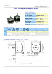
Position Loop Tuning Window<br />
Digital Scope<br />
Pulse Generator Settings<br />
Scope Settings<br />
The 1 st Dynamic Position Loop Parameter<br />
The 2 nd Position Loop Parameter<br />
Click Drive->Position Loop to open the position loop tuning window. The user can adjust the position loop PID parameters and see the<br />
result by clicking the Start button. A build-in Pulse Generator per<strong>for</strong>ms trapezoid velocity motion and the Digital Scope displays the<br />
motor’s actual velocity, current and position following error.<br />
Digital Scope<br />
Item Description Range<br />
Current (A) Current axis of the digital scope. Unit: Amp. -<br />
Velocity (rpm) Velocity axis of the digital scope. Unit: rpm -<br />
Position Error (p) Axis of Position following error in digital scope. Unit: Pulse -<br />
SW‐<strong>ACS306</strong>‐R20110826<br />
7
<strong>Software</strong> <strong>Operational</strong> <strong>Manual</strong> <strong>for</strong> <strong>ACS306</strong><br />
ProTuner Pulse Generator Settings<br />
Item Description Range<br />
Velocity (rpm) Target velocity of Pulse Generator. 1– 65535 rpm<br />
Acceleration (r/s^2) Acceleration of Pulse Generator. 1 – 65536 r/s^2<br />
Distance (s) Move distance of Pulse Generator. 1 – 65536 pulses<br />
Interval Interval between the positive and negative move. 1 – 65535 ms<br />
Repeat Times Repeat times. 1– 65535<br />
Scope Settings<br />
Item Description Range<br />
Current Actual measured current. Click to display it in the scope. -<br />
Position Error<br />
Position following error. The difference between commanded<br />
position and the actual measured position.<br />
-<br />
Velocity<br />
Actual measured velocity measured by the encoder. Ideally, this<br />
value should be as close as possible to the commanded velocity.<br />
-<br />
Trace Time Trace time of the digital scope. 100 – 3000ms<br />
SW‐<strong>ACS306</strong>‐R20110826<br />
8
<strong>Software</strong> <strong>Operational</strong> <strong>Manual</strong> <strong>for</strong> <strong>ACS306</strong><br />
The 1 st Position Loop Parameters<br />
When the motor speed is > APPROX. 500RPM, the 1 st position loop parameters take effect immediately <strong>for</strong> the motor behavior.<br />
Note: The 2 nd position loop parameters will be used when the motor speed is < APPROX. 10 RPM. If the motor speed is between 10 to<br />
500 RPM, the control parameter will switch to the 2 nd position loop smoothly.<br />
Item Description Range<br />
Kp<br />
Position Proportional Gain. Proportional Gain determines the<br />
response of the system to position errors. Low Proportional Gain<br />
provides a stable system (doesn’t oscillate), has low stiffness,<br />
and large position errors under load. Too large Proportional<br />
Gain values will cause oscillations and unstable systems.<br />
0 – 65536<br />
Kvff<br />
Velocity feed-<strong>for</strong>ward gain. Velocity feed-<strong>for</strong>ward speeds up<br />
the system response.<br />
0 – 65536<br />
Kd<br />
Position Derivative Gain. Derivative Gain provides damping<br />
by adjusting the output value as a function of the rate of change<br />
of error. A low value provides very little damping, which may<br />
cause overshoot after a step change in position. Large values<br />
have slower step response but may allow higher Proportional<br />
Gain to be used without oscillation.<br />
0 – 65536<br />
Vp<br />
Velocity Proportional Gain. Vp has similar effect as Kp but it<br />
is in the velocity loop.<br />
0 – 65536<br />
Vi<br />
Velocity Integral Gain. It can be used to reduce the steady error<br />
of velocity when the velocity is settled.<br />
0 – 65536<br />
Kaff<br />
Position Acceleration feed-<strong>for</strong>ward gain. It is used to reduce<br />
the position following error during acceleration and<br />
deceleration.<br />
0 – 65536<br />
SW‐<strong>ACS306</strong>‐R20110826<br />
9
<strong>Software</strong> <strong>Operational</strong> <strong>Manual</strong> <strong>for</strong> <strong>ACS306</strong><br />
The 2 nd Position Loop Parameters<br />
When the motor speed is< APPROX 10 RPM, the 2 nd position loop parameters take effect immediately <strong>for</strong> the motor behavior.<br />
Note: The 1 st position loop parameters will be used when the motor speed is > APPROX. 500 RPM. If the motor speed is between 10 to<br />
500 RPM, the control parameter will switch to the 1 st position loop smoothly.<br />
Item Description Range<br />
Kp<br />
Position Proportional Gain. Proportional Gain determines the<br />
response of the system to position errors. Low Proportional Gain<br />
provides a stable system (doesn’t oscillate), has low stiffness,<br />
and large position errors under load. Too large Proportional<br />
Gain values will cause oscillations and unstable systems.<br />
0 – 65536<br />
Ki<br />
Integral Gain. Integral Gain helps the control system<br />
overcome static position errors caused by friction or loading.<br />
The integrator increases the output value as a function of the<br />
position error summation over time. A low or zero value <strong>for</strong> the<br />
Integral Gain may have position errors at rest (that depend on<br />
the static or frictional loads and the Proportional Gain).<br />
Increasing the Integral Gain can reduce these errors. If the<br />
Integral Gain is too large, the systems may “hunt” (oscillate at<br />
low frequency) about the desired position.<br />
0 – 65536<br />
Kd<br />
Position Derivative Gain. Derivative Gain provides damping<br />
by adjusting the output value as a function of the rate of change<br />
of error. A low value provides very little damping, which may<br />
cause overshoot after a step change in position. Large values<br />
have slower step response but may allow higher Proportional<br />
Gain to be used without oscillation.<br />
0 – 65536<br />
Vp<br />
Velocity Proportional Gain. Vp has similar effect as Kp but it<br />
is in the velocity loop.<br />
0 – 65536<br />
Vi<br />
Velocity Integral Gain. It is used to adjust the steady velocity<br />
error when the velocity is stable.<br />
0 – 65536<br />
SW‐<strong>ACS306</strong>‐R20110826<br />
10
<strong>Software</strong> <strong>Operational</strong> <strong>Manual</strong> <strong>for</strong> <strong>ACS306</strong><br />
Scope<br />
Click Tool->Scope to open the scope which is built inside the drive. You can check the actual measured velocity, current and position<br />
following error in this window.<br />
Item Description Range<br />
Current (A) Current axis of the digital scope. Unit: Amp. -<br />
Velocity (rpm) Velocity axis of the digital scope. Unit: rpm -<br />
Position Error (p) Axis of Position following error in digital scope. Unit: Pulse -<br />
Current Actual measured current. Click to display it in the scope. -<br />
Position Error<br />
Position following error. The difference between commanded<br />
position and the actual measured position.<br />
-<br />
Velocity<br />
Actual measured velocity measured by the encoder. Ideally, this<br />
value should be as close as possible to the commanded velocity.<br />
-<br />
Trace Time Trace time of the digital scope. 100 – 3000ms<br />
Start/Sop button Click to turn on/off the scope. -<br />
SW‐<strong>ACS306</strong>‐R20110826<br />
11
<strong>Software</strong> <strong>Operational</strong> <strong>Manual</strong> <strong>for</strong> <strong>ACS306</strong><br />
Error Log Window<br />
Click Tool->Error Log to open the error log window. This window shows both the present status of each error event and their history.<br />
Item<br />
Description<br />
Over Current Protection will be activated when the motor current is over 20A.<br />
Over Voltage<br />
Protection will be activated when the input voltage is over 40+/-1V.<br />
Low Voltage<br />
N/A.<br />
Phase Error<br />
N/A.<br />
Encoder Error<br />
Protection will be activated when no encoder feedback signals or wrong encoder/hall sensor<br />
feedback signals connected to the <strong>ACS306</strong>.<br />
Limit Error<br />
N/A.<br />
Following Error<br />
Protection will be activated when position following error exceeds the Position Following<br />
Error Limit.<br />
Brake Error<br />
N/A.<br />
Sampling Error<br />
N/A.<br />
EEprom Error<br />
N/A.<br />
Error Counter<br />
Display the No. of the errors.<br />
Erase All Errors<br />
Clear the error log.<br />
SW‐<strong>ACS306</strong>‐R20110826<br />
12
<strong>Software</strong> <strong>Operational</strong> <strong>Manual</strong> <strong>for</strong> <strong>ACS306</strong><br />
Configuring the Drive<br />
If it is the first time setup, you can follow the steps below to configure the drive.<br />
1) Set motor related parameters such as motor pole pairs, encoder resolution and position following error.<br />
2) Tune the current loop parameters according to motor.<br />
3) Tune the 1 st position loop parameters <strong>for</strong> the high-speed per<strong>for</strong>mance.<br />
4) Tune the 2 nd position loop parameters <strong>for</strong> the low-speed per<strong>for</strong>mance.<br />
5) Save the changes to drive’s nonvolatile memory.<br />
!<br />
Notice<br />
The motor must be connected to the drive be<strong>for</strong>e trying to configure the drive.<br />
Current Loop Tuning<br />
The <strong>ACS306</strong>’s current loop need to be tuned be<strong>for</strong>e normal operation in order to get optimize responses with different motors. Otherwise<br />
the motor will be easily stall or howls when power-up. Below is the tuning process <strong>for</strong> a NEMA 23 motor with 24VDC supply voltage.<br />
Step 1: Click Drive->Current Loop to open the tuning window. Set Test Current 1 and start the tuning with small Kp and “zero” Ki.<br />
Here we set Kp 2000.<br />
Initial Value<br />
Kp = 2000<br />
Ki =0<br />
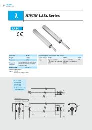
Step 2: Click the Test button and the plot window will show two curves. The red one is target current and the green one is actual<br />
current. There is large gap between them in the scope. It indicates that a large Kp needs to be introduced.<br />
SW‐<strong>ACS306</strong>‐R20110826<br />
13
<strong>Software</strong> <strong>Operational</strong> <strong>Manual</strong> <strong>for</strong> <strong>ACS306</strong><br />
Start Test:<br />
Proportional Gain = 2000<br />
Integral Gain = 0<br />
Step 3: Increase Kp to 3000 and click Test. The distance between target value and actual value is smaller but a higher Kp is still<br />
needed.<br />
↑ Proportional Gain:<br />
Kp = 3000<br />
Ki = 0<br />
Step 3: Give Kp 5000, 7000, 9000 and click the Test button, respectively. The green curve is getting more and more close to the red<br />
curve. Intersection appears when we increase Kp to 6000. It indicates that you need to stop increasing Kp and back off. Our purpose is<br />
to make the green curve (the actual current) close to the red curve (the target).<br />
SW‐<strong>ACS306</strong>‐R20110826<br />
14
<strong>Software</strong> <strong>Operational</strong> <strong>Manual</strong> <strong>for</strong> <strong>ACS306</strong><br />
↑ Proportional Gain:<br />
Kp =5000<br />
Ki = 0<br />
↑ Proportional Gain:<br />
Kp =7000<br />
Ki = 0<br />
SW‐<strong>ACS306</strong>‐R20110826<br />
15
<strong>Software</strong> <strong>Operational</strong> <strong>Manual</strong> <strong>for</strong> <strong>ACS306</strong><br />
Intersection<br />
↑ Proportional Gain:<br />
Kp =9000<br />
Ki = 0<br />
Step 4: Now the Kp is relatively good enough. But there is still distance between the green curve and the red curve when we use the<br />
mouse to zoom in the green curve. So we need to introduce Ki to reduce the distance or steady error at the constant part. It follows the<br />
same procedure as Kp. High Ki causes big vibration, system lag and makes the per<strong>for</strong>mance worse. The following figures show how to<br />
tune the Ki.<br />
Drag a triangle to zoom in<br />
SW‐<strong>ACS306</strong>‐R20110826<br />
16
<strong>Software</strong> <strong>Operational</strong> <strong>Manual</strong> <strong>for</strong> <strong>ACS306</strong><br />
Zero Integral Gain:<br />
Kp =9000<br />
Ki = 1<br />
↑Integral Gain:<br />
Kp =9000<br />
Ki = 200<br />
SW‐<strong>ACS306</strong>‐R20110826<br />
17
<strong>Software</strong> <strong>Operational</strong> <strong>Manual</strong> <strong>for</strong> <strong>ACS306</strong><br />
↑Integral Gain:<br />
Kp =Ki<br />
Ki = 400<br />
Step 5: The current loop tuning is basically finished. You can continue to adjust Kp and Ki <strong>for</strong> better per<strong>for</strong>mance. Now the updated<br />
Kp and Ki is just stored in the driver’s RAM. They will be lost when we power off the driver. Don’t <strong>for</strong>get to click Drive->Download<br />
To Drive to store the changed value to the drive’s nonvolatile EEPROM.<br />
!<br />
Notice<br />
You can reduce the Kp if the motor’s noise can not be accepted <strong>for</strong> the application.<br />
Save all the changes to the drive’s<br />
non-violated nonvolatile memory.<br />
SW‐<strong>ACS306</strong>‐R20110826<br />
18
<strong>Software</strong> <strong>Operational</strong> <strong>Manual</strong> <strong>for</strong> <strong>ACS306</strong><br />
Tuning the 1 st Position Loop Parameters<br />
Click Drive->Position Loop to open the tuning window. The follow example demonstrates the tuning of the 1 st position loop base on a<br />
NEMA23 motor with 24VDC input.<br />
!<br />
Notice<br />
The motor should be installed to the machine and connected to load be<strong>for</strong>e the position loop tuning.<br />
!<br />
Caution<br />
Move the load to the middle of the axis and make sure (40000/Encoder Resolution) turns of motor shaft will not hit<br />
anything. Otherwise, please reduce the distance setting in the pulse generator.<br />
Be<strong>for</strong>e tuning the 1 st position loop parameters, set pulse generator parameter as the following figure. We select the actual velocity and<br />
position following error to be displayed in the digital scope. Trace Time affects the display length of the curve. Here we select 1200ms.<br />
Pulse Generator and Scope Settings in this Example:<br />
Velocity = 1200rpm, Acceleration = 200r/s^2, Distance = 40000Pulse, Repeat Times = 1<br />
Check the Velocity and Position Error Curve, Trace Time = 1200ms<br />
SW‐<strong>ACS306</strong>‐R20110826<br />
19
<strong>Software</strong> <strong>Operational</strong> <strong>Manual</strong> <strong>for</strong> <strong>ACS306</strong><br />
The pulse generator will generate the following command trapezoid velocity profile. It takes 100ms to make the motor to accelerate<br />
from 0 to 1200 rpm.<br />
Velocity(RPM)<br />
1200<br />
900<br />
600<br />
300<br />
0<br />
-300<br />
-600<br />
-900<br />
-1200<br />
Commanded Trapezoid Velocity Curve<br />
Our purpose is to get the highest system stiffness but lower motor noise. The actual measured velocity should be similar as the<br />
commanded velocity curve. However, sometimes we need to trade off between them because high proportional gain leads to big<br />
overshoot and vibration. In this example, we start with small proportional gain then increase it. We will stop increasing when the motor<br />
noise can not be accepted. The Kaff and Kvff (Feed-<strong>for</strong>ward gain) will be increased to further reduce the position following error if<br />
necessary. The tuning procedure is shown as follows:<br />
1Kvff = 0, Kd = 100, Vi =0, Kaff = 0, Small Vp and Kp<br />
2Vp↑ , motor noise begins, Vp↓<br />
3Kp↑ , motor noise begins , Kp↓ 4Kaff↑, Kvff↑, Kd↑ (If necessary)<br />
Step 1: Set Vp = 100, Vi = 0, Kp = 500, Kaff = 0, Kd = 0. The initial value is depending on supply voltage, motor and reflected load<br />
inertia. The above valuses may not suitable <strong>for</strong> your system. Please adjust them according to different symptom as follows:<br />
• Decrease Vp/Kp if the motor generates big noise.<br />
• Increase Vp/Kp if the drive’s red LED blinks (Protection mode).<br />
Tip: Giving an external torque by rotating the motor shaft (or moving the load) manually is good way to check whether the Vp and Vd<br />
are suitable or not. If it is hard to rotate/move and the motor generates big noise, you should lower down Vp/Kp. If it is easy to<br />
rotate/move and even the drive goes into protection mode (the red LED blinks), you should increase Vp/Kp.<br />
Encoder<br />
Servo Motor<br />
Observe the motor noise/vibration when increasing loop gain<br />
Press the Start button to start the test. The motor shaft will move (40000/Encoder Resolution) turns in two directions. Several seconds<br />
later the actual measured velocity and position error curve are displayed in the scope as follows. We see that the position error is large<br />
and the velocity curve is very bad when comparing to the commanded one.<br />
SW‐<strong>ACS306</strong>‐R20110826<br />
20
<strong>Software</strong> <strong>Operational</strong> <strong>Manual</strong> <strong>for</strong> <strong>ACS306</strong><br />
Green Curve:<br />
Actual Measured Velocity.<br />
Pink Curve:<br />
Position Following Error.<br />
Kp = 500, Vp = 100,<br />
Kvff = Kd = Vi = Kaff = 0<br />
Step 2: Increase Vp until the actual velocity curve is like the commanded one. If the motor noise is large and can not be accepted,<br />
decrease it until it can be accepted. To activate the noise/vibration, sometimes you need to give a disturbance to the load by either<br />
clicking the Start button or trying to push/pull the load. In this example, we give Vp 400, 800, 1000 and find that the noise/vibration at<br />
Vp=1000 can be accepted. So we stop increasing Vp.<br />
Kp = 500, ↑Vp = 400,<br />
Kvff = Kd = Vi = Kaff = 0<br />
SW‐<strong>ACS306</strong>‐R20110826<br />
21
<strong>Software</strong> <strong>Operational</strong> <strong>Manual</strong> <strong>for</strong> <strong>ACS306</strong><br />
Kp = 500, ↑Vp = 800,<br />
Kvff = Kd = Vi = Kaff = 0<br />
Kp = 500, ↑Vp = 1000,<br />
Kvff = Kd = Vi = Kaff = 0<br />
SW‐<strong>ACS306</strong>‐R20110826<br />
22
<strong>Software</strong> <strong>Operational</strong> <strong>Manual</strong> <strong>for</strong> <strong>ACS306</strong><br />
Step 3: Increase Kp to maximize the system stiffness or minimize the position error until the motor noise/vibration can not be accepted,<br />
following the same way as Vp. See the figures below. We see that the peak position error reduce from 350 to 180 when<br />
increasing Kp to 4000.<br />
↑Kp = 1000, Vp = 1000,<br />
Kvff = Kd = Vi = Kaff = 0<br />
Position Error = 350<br />
↑Kp = 4000, Vp = 1000,<br />
Kvff = Kd = Vi = Kaff = 0<br />
Position Error = 180<br />
SW‐<strong>ACS306</strong>‐R20110826<br />
23
<strong>Software</strong> <strong>Operational</strong> <strong>Manual</strong> <strong>for</strong> <strong>ACS306</strong><br />
↑Kp = 8000, Vp = 1000,<br />
Kvff = Kd = Vi = Kaff = 0<br />
Position Error = 170<br />
↑Kp = 12000, Vp = 1000,<br />
Kvff = Kd = Vi = Kaff = 0<br />
Position Error = 160<br />
Now the system has been basically tuned. In the following step, the user can increase Kvff to further reduce the position<br />
following error if necessary. However, big noise may be introduced if high Kvff.<br />
Step 4: Increase the Kvff to 5000 and 10000. The position following error reduces to 80 and 30, respectively. See figures.<br />
SW‐<strong>ACS306</strong>‐R20110826<br />
24
<strong>Software</strong> <strong>Operational</strong> <strong>Manual</strong> <strong>for</strong> <strong>ACS306</strong><br />
Kp = 12000, Vp = 1000,<br />
↑Kvff = 5000<br />
Kd = Vi = Kaff = 0<br />
Position Error = 80<br />
Kp = 12000, Vp = 1000,<br />
↑Kvff = 10000<br />
Kd = Vi = Kaff = 0<br />
Position Error = 30<br />
Remember that tuning the servo is to get satisfying per<strong>for</strong>mances, getting the best per<strong>for</strong>mances of the servo is a time consuming work.<br />
So if the servo per<strong>for</strong>mance can meet your application requirements, then the easier tuning way the better. Just like if the per<strong>for</strong>mances of<br />
the products can meet your application requirements, then the cheaper the better.<br />
Step 5: Don’t <strong>for</strong>get to click Drive->Download To Drive to store the changed value to the drive’s nonvolatile EEPROM.<br />
SW‐<strong>ACS306</strong>‐R20110826<br />
25
<strong>Software</strong> <strong>Operational</strong> <strong>Manual</strong> <strong>for</strong> <strong>ACS306</strong><br />
Tuning the 2 nd Position Loop Parameters<br />
Click Drive->Position Loop to open the tuning window. The follow example demonstrates the tuning of the 1 st position loop base on a<br />
NEMA23 motor with 24VDC input.<br />
!<br />
Notice<br />
The motor should be installed to the machine and connected to load be<strong>for</strong>e the position loop tuning.<br />
!<br />
Caution<br />
Move the load to the middle of the axis and make sure (1000/Encoder Resolution) turns of motor shaft will not hit<br />
anything. Otherwise, please reduce the distance setting in the pulse generator.<br />
Be<strong>for</strong>e tuning the 2 nd position loop parameters, set pulse generator parameter as the following figure. We select the actual velocity and<br />
position following error to be displayed in the digital scope. Trace Time affects the display length of the curve. Here we select 1200ms.<br />
Pulse Generator and Scope Settings in this Example:<br />
Velocity = 30rpm, Acceleration = 200r/s^2, Distance = 1000Pulse, Repeat Times = 1<br />
Check the Velocity and Position Error Curve, Trace Time = 1200ms<br />
SW‐<strong>ACS306</strong>‐R20110826<br />
26
<strong>Software</strong> <strong>Operational</strong> <strong>Manual</strong> <strong>for</strong> <strong>ACS306</strong><br />
The pulse generator will generate the following command trapezoid velocity profile. It takes 2.5ms to make the motor to accelerate from<br />
0 to 30 rpm.<br />
Velocity(RPM)<br />
120<br />
90<br />
60<br />
30<br />
0<br />
-30<br />
-60<br />
-90<br />
-120<br />
Commanded Trapezoid Velocity Curve<br />
Our purpose is to get the highest system stiffness but lower motor noise. The actual measured velocity should be similar as the<br />
commanded velocity curve. However, sometimes we need to trade off between them because high proportional gain leads to big<br />
overshoot and vibration. In this example, we start with small proportional gain then increase it. We will stop increasing when the motor<br />
noise can not be accepted. The tuning procedure is shown as follows:<br />
1Kd = 100, Ki =100, Vi = 0, Small Vp and Kp<br />
2Vp↑ , motor noise begins, Vp↓<br />
3Kp↑ , motor noise begins , Kp↓ 4Kd↑, Ki↑(If necessary)<br />
Step 1: Set Vp = 400, Vi = 0, Kp = 1000, Ki= 100, Kd = 100. The initial value is depending on supply voltage, motor and reflected<br />
load inertia. The above valuses may not suitable <strong>for</strong> your system. Please adjust them according to different symptom as follows:<br />
• Decrease Vp/Kp if the motor generates big noise.<br />
• Increase Vp/Kp if the drive’s red LED blinks (Protection mode) or the motor vibrates.<br />
Tip: Giving an external torque by rotating the motor shaft (or moving the load) manually is good way to check whether the Vp and Kp<br />
are suitable or not. If it is hard to rotate/move and the motor generates big noise, you should lower down Vp/Kp. If it is easy to<br />
rotate/move and even the drive goes into protection mode (the red LED blinks), you should increase Vp/Kp.<br />
Encoder<br />
Servo Motor<br />
Observe the motor noise/vibration when increasing loop gain<br />
Press the Start button to start the test. The motor shaft will move (1000/Encoder Resolution) turns in two directions. Several seconds<br />
later the actual measured velocity and position error curve are displayed in the scope as follows. We see that the position error is large<br />
and the velocity curve is very bad when comparing to the commanded one.<br />
SW‐<strong>ACS306</strong>‐R20110826<br />
27
<strong>Software</strong> <strong>Operational</strong> <strong>Manual</strong> <strong>for</strong> <strong>ACS306</strong><br />
Green Curve:<br />
Actual Measured Velocity.<br />
Pink Curve:<br />
Position Following Error.<br />
Kp = 1000, Vp = 400<br />
Ki= Kd = 100, Vi = 0<br />
Step 2: Increase Vp until the actual velocity curve is like the commanded one. If the motor noise is large and can not be accepted,<br />
decrease it until it can be accepted. To activate the noise/vibration, sometimes you need to give a disturbance to the load by either<br />
clicking the Start button or trying to push/pull the load. In this example, we give Vp 600, 700,800 and find that the noise/vibration at<br />
Vp=800 can be accepted. So we stop increasing Vp.<br />
The velocity curve looks better.<br />
Kp = 1000, ↑Vp = 600<br />
Ki= Kd = 100, Vi = 0<br />
SW‐<strong>ACS306</strong>‐R20110826<br />
28
<strong>Software</strong> <strong>Operational</strong> <strong>Manual</strong> <strong>for</strong> <strong>ACS306</strong><br />
Kp = 1000, ↑Vp = 700<br />
Ki= Kd = 100, Vi = 0<br />
Kp = 1000, ↑Vp = 800<br />
Ki= Kd = 100, Vi = 0<br />
SW‐<strong>ACS306</strong>‐R20110826<br />
29
<strong>Software</strong> <strong>Operational</strong> <strong>Manual</strong> <strong>for</strong> <strong>ACS306</strong><br />
Step 3: Increase Kp to maximize the system stiffness or minimize the position error until the motor noise/vibration can not be accepted,<br />
following the same way as Vp. See the figures below. We see that the peak position error reduce a lot when increasing Kp to 2000.<br />
The velocity curve looks better.<br />
↑Kp = 2000, Vp = 800<br />
Ki= Kd = 100, Vi = 0<br />
↑Kp = 2500, Vp = 800<br />
Ki= Kd = 100, Vi = 0<br />
Now the system has been basically tuned. In the following step, the user can increase Kd to make the curve look more like the<br />
commanded one if necessary. However, the Kd is not sensitive.<br />
SW‐<strong>ACS306</strong>‐R20110826<br />
30
<strong>Software</strong> <strong>Operational</strong> <strong>Manual</strong> <strong>for</strong> <strong>ACS306</strong><br />
Step 4: Increase the Kvff to 5000 and 10000. The position following error reduces to 80 and 30, respectively. See figures.<br />
Kp = 2500, Vp = 800<br />
↑Kd = 1000<br />
Ki= 100, Vi = 0<br />
Remember that tuning the servo is to get satisfying per<strong>for</strong>mances, getting the best per<strong>for</strong>mances of the servo is a time consuming work.<br />
So if the servo per<strong>for</strong>mance can meet your application requirements, then the easier tuning way the better. Just like if the per<strong>for</strong>mances of<br />
the products can meet your application requirements, then the cheaper the better.<br />
Step 5: Don’t <strong>for</strong>get to click Drive->Download To Drive to store the changed value to the drive’s nonvolatile EEPROM.<br />
SW‐<strong>ACS306</strong>‐R20110826<br />
31
<strong>Software</strong> <strong>Operational</strong> <strong>Manual</strong> <strong>for</strong> <strong>ACS306</strong><br />
Contact Us<br />
China Headquarters<br />
Address: 3/F, Block 2, Nanyou Tianan Industrial Park, Nanshan District Shenzhen, China<br />
Web: http://www.leadshine.com<br />
Sales Hot Line:<br />
Tel: 86-755-2641-7674 (<strong>for</strong> Asia, Australia, Africa areas)<br />
86-755-2640-9254 (<strong>for</strong> Europe areas)<br />
86-755-2641-7617 (<strong>for</strong> Europe areas)<br />
Fax: 86-755-2640-2718<br />
Email: sales@leadshine.com.<br />
Technical Support:<br />
Tel: 86-755-2641-8447, 86-755-2641-8774, 86-755-2641-0546<br />
Fax: 86-755-2640-2718<br />
Email: tech@leadshine.com(<strong>for</strong> All)<br />
<strong>Leadshine</strong> U.S.A<br />
Address: 25 Mauchly, Suite 318 Irvine, Cali<strong>for</strong>nia 92618<br />
Tel: 1-949-608-7270<br />
Fax: 1-949-608-7298<br />
Web: http://www.leadshineUSA.com<br />
Email: sales@leadshineUSA.com and support@leadshineUSA.com.<br />
SW‐<strong>ACS306</strong>‐R20110826<br />
32