
Create successful ePaper yourself
Turn your PDF publications into a flip-book with our unique Google optimized e-Paper software.
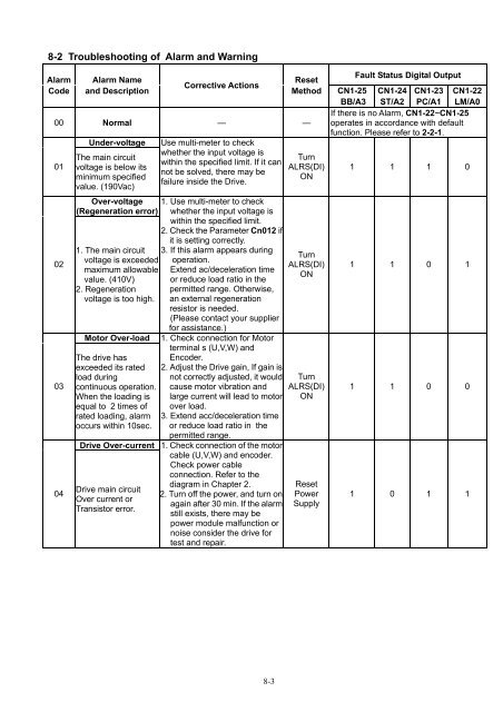
8-2 Troubleshooting of Alarm and Warning<br />
Alarm<br />
Code<br />
Alarm Name<br />
and Description<br />
Corrective Actions<br />
Reset<br />
Method<br />
00 Normal — —<br />
01<br />
02<br />
03<br />
04<br />
Under-voltage<br />
The main circuit<br />
voltage is below its<br />
minimum specified<br />
value. (190Vac)<br />
Over-voltage<br />
(Regeneration error)<br />
1. The main circuit<br />
voltage is exceeded<br />
maximum allowable<br />
value. (410V)<br />
2. Regeneration<br />
voltage is too high.<br />
Motor Over-load<br />
The drive has<br />
exceeded its rated<br />
load during<br />
continuous operation.<br />
When the loading is<br />
equal to 2 times of<br />
rated loading, alarm<br />
occurs within 10sec.<br />
Drive Over-current<br />
Drive main circuit<br />
Over current or<br />
Transistor error.<br />
Use multi-meter to check<br />
whether the input voltage is<br />
within the specified limit. If it can<br />
not be solved, there may be<br />
failure inside the Drive.<br />
1. Use multi-meter to check<br />
whether the input voltage is<br />
within the specified limit.<br />
2. Check the Parameter Cn012 if<br />
it is setting correctly.<br />
3. If this alarm appears during<br />
operation.<br />
Extend ac/deceleration time<br />
or reduce load ratio in the<br />
permitted range. Otherwise,<br />
an external regeneration<br />
resistor is needed.<br />
(Please contact your supplier<br />
for assistance.)<br />
1. Check connection for Motor<br />
terminal s (U,V,W) and<br />
Encoder.<br />
2. Adjust the Drive gain, If gain is<br />
not correctly adjusted, it would<br />
cause motor vibration and<br />
large current will lead to motor<br />
over load.<br />
3. Extend acc/deceleration time<br />
or reduce load ratio in the<br />
permitted range.<br />
1. Check connection of the motor<br />
cable (U,V,W) and encoder.<br />
Check power cable<br />
connection. Refer to the<br />
diagram in Chapter 2.<br />
2. Turn off the power, and turn on<br />
again after 30 min. If the alarm<br />
still exists, there may be<br />
power module malfunction or<br />
noise consider the drive for<br />
test and repair.<br />
Turn<br />
ALRS(DI)<br />
ON<br />
Turn<br />
ALRS(DI)<br />
ON<br />
Turn<br />
ALRS(DI)<br />
ON<br />
Reset<br />
Power<br />
Supply<br />
Fault Status Digital Output<br />
CN1-25<br />
BB/A3<br />
CN1-24<br />
ST/A2<br />
CN1-23<br />
PC/A1<br />
CN1-22<br />
LM/A0<br />
If there is no Alarm, CN1-22~CN1-25<br />
operates in accordance with default<br />
function. Please refer to 2-2-1.<br />
1 1 1 0<br />
1 1 0 1<br />
1 1 0 0<br />
1 0 1 1<br />
8-3