Create successful ePaper yourself
Turn your PDF publications into a flip-book with our unique Google optimized e-Paper software.
Timing for Brake output signal<br />
Set the required time for the operation of brake output signal (BI) according to the following.<br />
BI output can be used to control the function of an external electro-mechanical brake.<br />
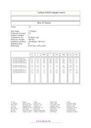
Parameter Name Default Default Setting Range Control Mode<br />
Cn003<br />
Output time setting for<br />
Mechanical Brake<br />
Signal<br />
0 msec -2000~2000 ALL<br />
Note!<br />
To use brake output signal set Cn008 (Brake mode) to selections 1 or 3 as required.<br />
When the servo system has vertical loading, please set Cn003 to a Positive Number.<br />
For definition of a time value with a positive or a negative sign refer to the following<br />
notes and timing diagrams.<br />
(1) Cn003 set to a time value with a Positive sign.<br />
AS soon as the input contact SON is switched on, Servo on is activated at the same time,<br />
then after a time delay set by parameter Cn003,Output Contact BI is switched on. (Signal to release the<br />
brake).<br />
When SON input contact is switched off, BI output contact is also switched off (Signal to operate the<br />
brake).<br />
Then after a time delay set by parameter Cn003, Servo ON is de-activated.<br />
(2) Cn003 set to a time value with a Negative sign.<br />
AS soon as the input contact SON is switched on, Output Contact BI is switched on at the same time.<br />
(Signal to release the brake). then after a time delay set by parameter Cn003, Servo on is activated.<br />
When SON input contact is switched off, Servo ON is de-activated at the same time.<br />
then after a time delay set by parameter Cn003, Output Contact BI is switched off. (Signal to operate the<br />
brake).<br />
1<br />
1<br />
1<br />
1<br />
1<br />
1<br />
Note: Input contacts status of above time sequence diagram “1” (ON) and “0” (OFF).<br />
Please check 5-6-1 to set the required high /Low signal levels (PNP/NPN) selection.<br />
5-67