Inverter V5/F5 Series - T2 CNC
Inverter V5/F5 Series - T2 CNC
Inverter V5/F5 Series - T2 CNC

Create successful ePaper yourself
Turn your PDF publications into a flip-book with our unique Google optimized e-Paper software.
<strong>Inverter</strong> <strong>V5</strong>/<strong>F5</strong> <strong>Series</strong><br />
User Manual<br />
Xinje Electronic Co., Ltd.<br />
2008.01
<strong>V5</strong>/<strong>F5</strong> series inverter<br />
<strong>V5</strong> <strong>Series</strong><br />
<strong>Inverter</strong><br />
User Manual<br />
Table of Contents<br />
Preface<br />
———————————————<br />
Safty Precautions<br />
———————————————<br />
Product Introductions<br />
———————————————<br />
Installation<br />
ation and Wiring<br />
———————————————<br />
Operation<br />
Descriptions<br />
———————————————<br />
Function Parameters<br />
———————————————<br />
Fault Diagnos<br />
iagnosis<br />
is and Disposal<br />
———————————————<br />
Maintenance<br />
———————————————<br />
Communication Protocol<br />
———————————————<br />
1<br />
3<br />
11<br />
22<br />
42<br />
59<br />
181<br />
189<br />
193
<strong>V5</strong>/<strong>F5</strong> seires inverter<br />
This manual includes the basic caution items that you should obey to ensure your<br />
personal safety, as well as to protect the product and the connected equipments.<br />
These items are highlighted in the manual by a warning triangle. Please comply with<br />
the essential electric operation rules that are not indicated in this manual.<br />
Installing Precautions<br />
Please comply with these items, incorrect operation may cause the system<br />
error working even abnormal. More serious would cause possession loss.<br />
Correct Applications<br />
The device and its components can only be used in the applications described in<br />
the catalog and the technical manuals, can only be connected with devices or<br />
components from other manufacturers which have been approved or<br />
recommended by Xinje.<br />
The products will run normally in the condition of been transported, stored,<br />
configured and installed correctly, been operated and maintained as<br />
recommended.<br />
Xinje Electronic Co., Ltd. Copyright reserved<br />
Without written authority, please do not copy, transfer or use this document and its<br />
content. Anyone who disobeys this should take responsibility for the loss.<br />
Obligation Declare<br />
We have checked and confirmed that the contents in this manual were compatible<br />
with the hardware and software described. Since mistakes are hard to avoid, we<br />
cannot promise total accordant. This manual is subject to change without notices.
<strong>V5</strong>/<strong>F5</strong> series inverter<br />
Table of Contents<br />
Preface.......................................................................................................1<br />
Safety Precautions.....................................................................................3<br />
1 Product Instruction............................................................................... 11<br />
1-1. Product Overview.................................................................... 11<br />
1-2. Product Technical Specification.............................................. 13<br />
1-3. Product Appearance:................................................................ 18<br />
1-4. Product Dimension...................................................................19<br />
1-5. Choose The Accessories.......................................................... 20<br />
2 Installation and Wiring.........................................................................22<br />
2-1. Installation Environment......................................................... 22<br />
2-1-1. Environment Requirement..............................................22<br />
2-1-2. Mounting Direction and Space.......................................22<br />
2-1-3. Mounting and Removing of The Frontal Panel..............23<br />
2-2. Precautions When Wiring........................................................ 24<br />
2-3. Wiring With The Main Circuit’s Terminals..............................26<br />
2-3-1. Wiring Diagram.............................................................. 26<br />
2-3-2. Terminal Description...................................................... 26<br />
2-4. Basic Running Wiring..............................................................28<br />
2-5. Configuration and Wiring of Control Circuit.......................... 29<br />
2-5-1.Relative Position Between Terminals and jumpers and<br />
function Descriptions................................................................ 29<br />
2-5-2.Description of Terminals On The Control Board............ 30<br />
2-5-3. Wiring of Analog input/output terminals........................34<br />
2-5-4. Connection of The Communication Terminals...............36<br />
2-6. Installation Guidance According To EMC Requirement.........38<br />
i
<strong>V5</strong>/<strong>F5</strong> seires inverter<br />
2-6-1. Suppressing The Noise................................................... 38<br />
2-6-2. Local Wiring And Grounding......................................... 40<br />
3 Operating Instructions..........................................................................42<br />
3-1. Running of The <strong>Inverter</strong>...........................................................42<br />
3-1-1. Control mode of running command................................42<br />
3-1-2. Frequence setting mode.................................................. 43<br />
3-1-3. Running state.................................................................. 43<br />
3-1-4. Running modes............................................................... 43<br />
3-2. Panel and its operation methods.............................................. 46<br />
3-2-1. Panel description.............................................................46<br />
3-2-2. Function description of panel keys.................................47<br />
3-2-3. Fucntion description of LED and indicator.................... 48<br />
3-2-4. Display of the operation panel........................................49<br />
3-2-5. Panel operation procedure.............................................. 52<br />
3-3. Start-up.....................................................................................57<br />
3-3-1. Checking before starting up............................................57<br />
3-3-2. Start up the inverter for the first time............................. 57<br />
4 Function Parameters.............................................................................59<br />
4-1. Function parameter table......................................................... 59<br />
4-2. Parameter description.............................................................105<br />
4-2-1. Basic operating function parameters(Group P0).....105<br />
4-2-2. Parameters of reference frequency(Group P1)........117<br />
4-2-3. Starting and braking parameters(Group P2)........... 120<br />
4-2-4. Auxiliary running parameters(Group P3)................124<br />
4-2-5. Function parameters of terminal(Group P4)........... 135<br />
4-2-6. Protective function parameters(Group P5)............. 153<br />
4-2-7. Fault recording parameters(Group P6)....................158<br />
4-2-8.Close-loop control parameters (Group P7)................... 159<br />
ii
<strong>V5</strong>/<strong>F5</strong> series inverter<br />
4-2-9. Simple PLC operation parameters.(Group P8)....... 167<br />
4-2-10.Traverse and measure function parameters(Group P9)<br />
................................................................................................. 172<br />
4-2-11. Vector control parameters(Group PA)................... 176<br />
4-2-12. Specail application function parameters(Group PB)<br />
................................................................................................. 179<br />
4-2-13. Factory setting(Group PF).....................................180<br />
5 Fault Diagnosis and Countermeasures...............................................182<br />
5-1. Fault diagnosis and countermeasurs...................................... 182<br />
5-2. Fault records...........................................................................187<br />
5-3. Fault reset...............................................................................187<br />
6 Maintenance....................................................................................... 189<br />
6-1. Maintenance...........................................................................189<br />
6-1-1. Routine maintenance.................................................... 189<br />
6-2. Periodical care and maintenance............................................190<br />
6-2-1.Periodical care............................................................... 190<br />
6-2-2. Periodical maintenance.................................................191<br />
6-3. Warranty of the inverter......................................................... 191<br />
7 Communication Protocol................................................................... 193<br />
7-1. Overview of communication protocol...................................193<br />
7-2. Instruction of communication protocal..................................194<br />
7-2-1. Communicating mode...................................................194<br />
7-2-2. Communication modes................................................. 195<br />
7-2-3. Mode of communication port....................................... 195<br />
7-3.Modbus-RTU communication protocol..................................196<br />
7-3-1. Structure........................................................................196<br />
7-3-2. Communication information.........................................196<br />
7-3-3.Communication parameter............................................ 199<br />
iii
<strong>V5</strong>/<strong>F5</strong> seires inverter<br />
iv
<strong>V5</strong>/<strong>F5</strong> series inverter<br />
Preface<br />
——Essential introduction for this manual<br />
Thank you for purchasing <strong>V5</strong>/<strong>F5</strong> series inverter manufactured by Xinje<br />
Electronic Co., Ltd, this manual should be read and understood before<br />
attempting relevant operations.<br />
1. Purpose of this manual<br />
This manual offers guidance and introductions about how to use and<br />
maintains the inverter correctly, including functions, usages,<br />
installation, maintenance, etc.<br />
2. Qualified personnel<br />
This manual is intent for the following personnel:<br />
‣ <strong>Inverter</strong> installation personnel<br />
‣ Project technical personnel(electric engineer, electrician)<br />
‣ Design personnel<br />
The above personnel should read and understand this manual carefully<br />
before operating and debugging.<br />
3. Validity of this manual<br />
This manual may only be used for inverters made by Xinje.<br />
4. Electronic Documents<br />
In addition to our written manuals, we offer electronic documentations<br />
of our products by the following ways.<br />
1
<strong>V5</strong>/<strong>F5</strong> seires inverter<br />
‣ User CD<br />
There are software, user manual and application tip of relevant products.<br />
‣ Website<br />
Please visit Thinget Electronic Co.,Ltd. at www.thinget.com to obtain all<br />
variable electronic documents.<br />
2
<strong>V5</strong>/<strong>F5</strong> series inverter<br />
Safety Precautions<br />
——Essential<br />
introduction about product operation<br />
Upon unpacking, please confirm that: Check whether the model and the<br />
rated values on the nameplate of the inverter are in accordance with your<br />
order. Check if there is any damage occurred during transportation;<br />
pleases contact us or the distributor if you find any missing or damage of<br />
the products.<br />
In order to use this product correctly, the user who uses the product for<br />
the first time must read this manual carefully and pay close attention to<br />
the safety precautions.<br />
Please keep this manual properly, hand it to the terminal user and lay it<br />
on the place where the operators can read it easily.<br />
◎ Safty Precautions ◎<br />
Confirmations Upon Delivery<br />
• Installation<br />
Notice<br />
1. Never install an inverter that is damaged or missing components.<br />
Doing so can result in injury.<br />
Notice<br />
1. Always hold the bottom of the inverter when carrying it. If the<br />
inverter is held by the front cover, the main body of the inverter may<br />
3
<strong>V5</strong>/<strong>F5</strong> series inverter<br />
fall, possible resulting in injury.<br />
2. Attach the inverter to metal or other noncombustible materials. Fire<br />
can result if the inverter is attached to a combustible material.<br />
3. Install a cooling fan or other cooling device when installing more<br />
than one inverter in the same enclosure so that the temperature of<br />
the air entering the inverters is below 45℃. Overheating can result<br />
in fires or other accidents.<br />
• Wiring<br />
4<br />
Danger<br />
1. Always turn off the input power supply before wiring. Otherwise, an<br />
electric shock or fire may occur.<br />
3. Wiring must be operated by an authorized person qualified in<br />
electrical work. Otherwise, an electric shock or fire may occur.<br />
5. Make sure to ground the ground terminals. Otherwise, an electric<br />
shock or fire may occur.<br />
7. Always check the operation of any emergency stop circuits after<br />
they are wired. Otherwise, possibly result in injury ( user<br />
responsibility for the wiring).<br />
9. Never touch the output terminal directly by your hands or let the<br />
output terminals to come into contact with the inverter case. Never<br />
short the output terminals. Otherwise, an electric short or ground<br />
short may occur.<br />
6. Never touch the internal circuit or the zero-component until power<br />
off and the charge indicator is off as there may still be high voltage i
<strong>V5</strong>/<strong>F5</strong> series inverter<br />
nside the AC motor dirver.<br />
Notice<br />
1. Confirm that the voltage of the main AC power supply satisfies the<br />
rated voltage of the <strong>Inverter</strong>. Injury and fire may occur if the voltage<br />
is not right.<br />
2. Do not perform voltage withstand tests on the <strong>Inverter</strong>. Otherwise,<br />
semiconductor elements and other devices can be damaged.<br />
4. Connect braking resistors, Braking Resistor Units, and Braking<br />
Units as shown in the I/O wiring examples. Otherwise, a fire may<br />
occur.<br />
4. Tighten all terminal screws to the specified tightening torque.<br />
Otherwise, a fire may occur.<br />
5. Do not connect AC power to output terminals U, V, and W.<br />
The interior parts of the <strong>Inverter</strong> will be damaged if voltage is<br />
applied to the output terminals.<br />
6. Do not connect phase-advancing capacitors or LC/RC noise filters<br />
to the output circuits.The <strong>Inverter</strong> may be damaged or internal parts<br />
burnt if these devices are connected.<br />
7. Do not connect electromagnetism switch, electromagnetism<br />
contactor to output circuit. When the inverter is running with load,<br />
the electromagnetism switch and electromagnetism contactor will<br />
generate inrush current which will cause inverter’s over current<br />
protection.<br />
8. Do not disassemble the whole front cover as disassembling the top<br />
front while wiring is ok. Otherwise, inverter internal parts may be<br />
damaged.<br />
5
<strong>V5</strong>/<strong>F5</strong> series inverter<br />
• Maintenance<br />
and Inspection<br />
Danger<br />
1. Do not touch the inverter terminals, as they may carry high voltage.<br />
Otherwise, an electric short may occur.<br />
2. Make sure to have protective cover .Always have the protective<br />
cover in place when power is being supplied to the <strong>Inverter</strong>. When<br />
attaching the cover, please with the power turns off.<br />
Otherwise, an electric short may occur.<br />
3. Maintenance, inspection, must be performed only by authorized<br />
personnel.<br />
Otherwise, an electric short may occur.<br />
Notice<br />
1. A CMOS IC is used in the control board. Handle the control board<br />
and CMOS IC carefully. The CMOS IC can be destroyed by static<br />
electricity if touched directly.<br />
2 . Do not change the wiring, or remove connectors or the Digital<br />
Operator, during operation.<br />
Otherwise, The devices may be damaged.<br />
6
<strong>V5</strong>/<strong>F5</strong> series inverter<br />
◎ Usage Precautions ◎<br />
‣ Constant torque low speed running<br />
When the inverter outputs to a common motor at low speed for a long<br />
term, the output rated torque should be derated due to the worsening<br />
radiating effect. If low speed constant torque long term running is<br />
required, then a special variable frequency motor is needed.<br />
‣ Motor insulation<br />
When using the <strong>V5</strong>/<strong>F5</strong> series inverter, make sure to confirm the<br />
insulation of the motor which will be used to avoid device damage.<br />
Besides, do the periodic check for the insulation condition of the motor<br />
located in the bad environment to guarantee the system can operate<br />
safely.<br />
‣ Negative torque over load<br />
If in the case of improving over load, negative torque may occur.<br />
Braking units should be connected with the inverter, or over current and<br />
over voltage fault may happen.<br />
‣ Mechanical<br />
resonance point of load<br />
The inverter may encounter the mechanical resonance point of load<br />
within certain output frequency range. Jump frequencies have to set to<br />
avoid it.<br />
‣ Capacitor and resistor<br />
Because the inverter output pulse wave, capacitor and resistors shouldn't<br />
be connected with the output terminals of the inverter, or the inverter<br />
may trip or components may be damaged; Besides, don’t connect switch<br />
components such as air switch and contactor with the output terminals is<br />
7
<strong>V5</strong>/<strong>F5</strong> series inverter<br />
recommended, as shown in Fig.0-1(If switch components need to be<br />
connected with the output terminals, make sure output current of the<br />
inverter is zero when switch is acting).<br />
8<br />
Fig.0-1 Capacitor is prohibited to be connected with<br />
output terminals of inverter<br />
‣ Deration according to basic frequency setting<br />
When the basic frequency is lower than the reference frequency, please<br />
consider duration for the motor so as to avoid motor’s damage caused by<br />
overheating.<br />
‣ Running at frequency above 50Hz<br />
If running at frequency above 50Hz, besides the increment of vibration<br />
and noise, the ranges of running speed of motor shaft and mechanical<br />
device have to be guaranteed. Be sure to make an enquiry first.<br />
‣ The electro-thermal protective value of motor<br />
If the applicable motor is selected as per requirements, the inverter can<br />
perform the thermal protection to the motor. If the ratings of applied<br />
motor are not in compliance with the inverter, be sure to adjust the<br />
protective value or adopt other protective measures to guarantee the safe
<strong>V5</strong>/<strong>F5</strong> series inverter<br />
running of motor.<br />
‣ Altitude and deration<br />
When the altitude is higher than 1000m, the cooling effect of inverter is<br />
deteriorated because of the rareness of air, deration must be considered,<br />
shown in Fig.0-2 which indicates the relationship between the altitude<br />
and rated current of frequency inverter.<br />
Fig. 0-2 The relationship between the altitude and rated<br />
‣ About protection<br />
classes<br />
current of frequency inverter<br />
The protection class of <strong>V5</strong>/<strong>F5</strong> series inverter IP20 is reached in the case<br />
of status display unit or keyboard.<br />
9
<strong>V5</strong>/<strong>F5</strong> series inverter<br />
◎ Note Regarding Disposal ◎<br />
When you dispose inverter, please pay attention that:<br />
Explosion risk of capacitor: The capacitors in the main circuits may<br />
explode when they are burned.<br />
Waste gas when plastic parts are burned: Poisonous gas may be<br />
generated when front panel is burned.<br />
Dispose method: Please dispose as industrial rubbish.<br />
10
<strong>V5</strong>/<strong>F5</strong> series inverter<br />
1 Product Instruction<br />
1-1. Product overview<br />
<strong>V5</strong>/<strong>F5</strong> series inverter is produced by Thinget Co., Ltd with high<br />
performance, easy operating and low noise. It is a innovative product<br />
with a series advanced and practical running and control functions such<br />
as practical PI, flexible input and output terminals, parameter<br />
modification online, fixed length control, traverse operation, RS485<br />
control, bus-mastering. It provides OEM customers with high integrated,<br />
reliable, cost-effective solution.<br />
Name Designation Rules<br />
V 5 - 2 0 P 7<br />
<strong>Inverter</strong> <strong>Series</strong><br />
<strong>V5</strong>: VVVF<br />
<strong>F5</strong>:Vector Control<br />
Voltage Level<br />
2:200V<br />
4:400V<br />
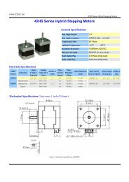
Max Motor's Capacity<br />
0P7:0.75KW<br />
1P5:1.5KW<br />
The rest may be deduced by<br />
analogy<br />
(P:Stands for radix Point)<br />
型<br />
11
<strong>V5</strong>/<strong>F5</strong> series inverter<br />
<strong>V5</strong> <strong>Series</strong> of <strong>Inverter</strong><br />
Input Voltage<br />
220V<br />
Single-phase<br />
Model<br />
Rated Capacity<br />
(KVA)<br />
Rated Output Current<br />
(A)<br />
Motor's Power<br />
(KW)<br />
<strong>V5</strong>-20P7 1.5 4.7 0.75<br />
<strong>V5</strong>-21P5 2.8 7.5 1.5<br />
380V<br />
Three-phase<br />
<strong>V5</strong>-41P5 2.5 4.0 1.5<br />
<strong>V5</strong>-42P2 3.0 6.0 2.2<br />
<strong>V5</strong>-43P7 5.9 9.6 3.7<br />
<strong>V5</strong>-45P5 8.5 14.0 5.5<br />
<strong>V5</strong>-47P5 11 17.0 7.5<br />
12
<strong>V5</strong>/<strong>F5</strong> series inverter<br />
1-2. Product technical<br />
specification<br />
1.Technical<br />
specification<br />
200V<br />
Type <strong>V5</strong>-2 _ _ _ 0P7<br />
1P5<br />
Output Match Motor(KW) 0.75 1.5<br />
Output Current(A) 4.7 7.5<br />
Voltage(V) AC 200<br />
Frequency Range(Hz) 0~500<br />
Frequency Resolution(Hz) 0.01<br />
Over-loading Ability<br />
150%Rated Current for 1 minutes,180%<br />
Rated Current for 1 second<br />
Input Rated Voltage/Frequency Single-phase 220V,50/60Hz<br />
AC voltage permit<br />
fluctuate range<br />
Frequency fluctuate Range<br />
Voltage:-20% ~ +20%<br />
Voltage Unbalance Rate:
<strong>V5</strong>/<strong>F5</strong> series inverter<br />
Model <strong>V5</strong>-4_ _ _<br />
1P5<br />
2P2<br />
3P7<br />
5P5<br />
7P5<br />
Output Motor(KW) 1.5 2.2 3.7 5.5 7.5<br />
Input<br />
Output Current(A) 4.0 6.0 9.6 14.0 17.0<br />
Voltage(V) AC 380<br />
Frequency Range (Hz)<br />
Frequency<br />
(Hz)<br />
Over load Ability<br />
Rated Current<br />
/Frequency<br />
accuracy<br />
AC voltage fluctuate<br />
range<br />
Frequency<br />
range<br />
fluctuate<br />
0 ~500<br />
0.01<br />
150% Rated Current for 1 minute,180% Rated<br />
Current for 1 Second<br />
Three-phase 380V;50Hz/60Hz<br />
Voltage:-20% ~ +20%<br />
Voltage Unbalance Rate:
<strong>V5</strong>/<strong>F5</strong> series inverter<br />
Vibration<br />
Less than 5.9 m/s 2 (0.6M)<br />
Storage Temperature -20℃~+60℃<br />
Structure Protect Configuration IP20(In the state of "state display units"<br />
or "keyboard")<br />
Cooling Manner Fan cooling<br />
Installation<br />
Surface mounted or install inside cabinet<br />
2. General Specification<br />
15
models<br />
<strong>V5</strong>/<strong>F5</strong> series inverter<br />
Main<br />
Control<br />
Function<br />
16<br />
Modulation<br />
Control models<br />
Frequency<br />
definition<br />
Frequency<br />
accuracy<br />
Start frequency<br />
Torque boost<br />
V/F curve<br />
Acc/Dec curve<br />
DC injection<br />
braking<br />
Dynamic<br />
braking<br />
Jog<br />
Internal PI<br />
Multi-step<br />
speed running<br />
Auto<br />
Traverse<br />
operation<br />
regulation<br />
voltage<br />
Optimized space voltage vector SVPWM<br />
modulation<br />
Space voltage vector SVPWM control(Optimized<br />
compensation characteristic in low frequency dead<br />
zone)<br />
Digital Setting: ×±0. 01% highest frequency;<br />
Analog Setup: ×±0.2% highest frequency<br />
Digital Setting:0.01Hz;<br />
Analog Setup:×0.1% highest frequency<br />
0.40Hz~20.00Hz<br />
Auto torque boost,manual torque boost 0.1%~<br />
30.0%<br />
Five modes : constant torque V/F curve, 1 V/F<br />
curve mode by user and 3 kinds of torque-derating<br />
modes (2.0 order, 1.7 order, 1.2 order)<br />
Two modes:linear Acc/Dec, S ramp Acc/Dec;<br />
seven kinds of Acc/Dec time (Maximum:6000<br />
minutes) and unit(minute or second) is selectable.<br />
Initial frequency of DC injection braking process:<br />
0~15.00Hz<br />
Braking time:0~60.0 s<br />
Braking current:0~80%<br />
Internal dynamic braking,can be connected with<br />
external braking resistor<br />
Range of jog frequendy : 0.1Hz ~ 50.00Hz,<br />
Acc/Dec time of jog operation 0.1~60.0s<br />
Be able to form close loop control system easily<br />
Multi-step speed running can be realized by internal<br />
PLC or control terminals<br />
Traverse operation with adjustable central<br />
frequency<br />
When souce voltage changes, the modulationg rate<br />
can be adjusted automatically,so the output voltage
<strong>V5</strong>/<strong>F5</strong> series inverter<br />
17
<strong>V5</strong>/<strong>F5</strong> series inverter<br />
1-3. Product appearance:<br />
Top cover<br />
Operation panel<br />
Control circuit<br />
termianls<br />
Power terminals<br />
Panel<br />
Ventilation hole<br />
FA<br />
Mounting hole<br />
Nameplate<br />
18
<strong>V5</strong>/<strong>F5</strong> series inverter<br />
1-4. Product dimension<br />
Dimension of Installation Holes(Unit<br />
Unit:mm<br />
mm)<br />
Specification W D1 L D2 H<br />
<strong>V5</strong>-20P7<br />
<strong>V5</strong>-21P5<br />
<strong>V5</strong>-41P5<br />
<strong>V5</strong>-42P2<br />
<strong>V5</strong>-43P7<br />
<strong>V5</strong>-45P5<br />
<strong>V5</strong>-47P5<br />
138 114 215 204 152<br />
182 140 325 319 152<br />
19
<strong>V5</strong>/<strong>F5</strong> series inverter<br />
1-5. Choose fittings<br />
‣ Brake Resistor<br />
<strong>V5</strong> series inverter include brake unit. If you have any energy expenditure<br />
brake requirement, please choose suitable brake resistance according to<br />
figure 1-1.<br />
Figure 1-1 Wiring of inverter and brake units<br />
Table 1-1 Brake resistor selection<br />
Model<br />
Motor Power<br />
Resistor Value<br />
Resistor power<br />
(KW)<br />
(Ω)<br />
(W)<br />
<strong>V5</strong>-20P7 0.75 150 200<br />
<strong>V5</strong>-21P5 1.5 100 400<br />
<strong>V5</strong>-41P5 1.5 300 400<br />
<strong>V5</strong>-42P2 2.2 200 500<br />
<strong>V5</strong>-43P7 3.7 200 500<br />
<strong>V5</strong>-45P5 5.5 100 500<br />
<strong>V5</strong>-47P5 7.5 75 1000<br />
20
<strong>V5</strong>/<strong>F5</strong> series inverter<br />
21
<strong>V5</strong>/<strong>F5</strong> series inverter<br />
2 Installation and Wiring<br />
2-1. Installation environment<br />
2-1-1. Environment requirement<br />
‣ Ambient tempeature: It is required to be within the range of -<br />
10ºC~40ºC. The inverter should be derated when the temperature<br />
over 40ºC, at the same time ventilation and heat dissipation should<br />
be enhanced.<br />
‣ Far away from the location with direct sunlight, dust, floating fiber<br />
or metal powder.<br />
‣ Mount in the location free of corrosive gas and combustible gas.<br />
‣ Mount in the location free of condensing, dry bulb and the humidity<br />
should less then 95%RH.<br />
‣ Mount in the location where vibration less than 5.9m/s²(0.6G)<br />
‣ Far away from electramagnetism interfere source and other electric<br />
instruments sensitive with electramagnetism interfere.<br />
2-1-2. Mounting location<br />
‣ Mount the inverter vertically under general condition.<br />
‣ The requirement of space and distance are shown in Fig. 2-1.<br />
‣ When several inverters are mounted up and down, air flow diverting<br />
plate should be fixed in between as shown in Fig. 2-2.<br />
22
<strong>V5</strong>/<strong>F5</strong> series inverter<br />
Air flow<br />
diverting plate<br />
Fig. 2-1 Mounting Space<br />
Fig.2-2 Mounting of Multiple <strong>Inverter</strong>s<br />
2-1-3. Mounting and removing<br />
‣ Removing: Romove the four screws on the cover with phillips<br />
screwdriver<br />
‣ Mounting: Allign the mounting holes and then fix the screws.<br />
23
<strong>V5</strong>/<strong>F5</strong> series inverter<br />
2-2. Wiring<br />
Caution<br />
• Wiring after power off for at least 10 minutes, otherwise, an<br />
electronic short may occur.<br />
• Do not connect AC power to output terminals U, V and W.<br />
• Both the inverter and the motor should be grounded to guarantee<br />
safty as there may be leakage current with the inverter.The cross<br />
section of earthing copper cable must be above 3.5mm².<br />
• Dielectric strength test of the inverter has been done in factory, so<br />
you need not do it again.<br />
• Do not install electromagnetic contactor, absorption capacitor or<br />
other absorption resistance-capacitance devices, as shown in Fig3-3.<br />
• The inverter should be connected with the power supply via breaker<br />
to provide over-current protection and convenience for<br />
disconnecting the AC supply to maintain the inveter.<br />
• The wiring of relay input and output circuit (X1~X6, FWD, REV,<br />
OC, DO) should select the twisted-pair or shield cable with cross<br />
section over 0.75 mm². One terminal of the shield layer should be<br />
hung in air and the other terminal should be connected with the<br />
inverter’s grounding terminal E with lenth less than 50m.<br />
24<br />
Danger
<strong>V5</strong>/<strong>F5</strong> series inverter<br />
• The cover can be removed only when the power is switched off,<br />
all the LEDs on the panel are off and waiting at least for 10<br />
minutes.<br />
• Wiring work can be performed until the voltage between internal<br />
electrolesis capacity “+” and “–“ below DC36V.<br />
• Wiring work can only be done by trained and professional<br />
personnel.<br />
• Before usage, check whether the main voltage is suitable for the<br />
requirement of inverter input voltage.Otherwise, injury and<br />
device damage may be occur.<br />
25
<strong>V5</strong>/<strong>F5</strong> series inverter<br />
2-3. Wiring of main<br />
circuit terminals<br />
2-3-1. Wiring diagram<br />
Fig. 2-3 Wiring of main circuit<br />
2-3-2. Terminal description<br />
Main circuit input/output terminals are shown in Table2-1.<br />
Table 2-1 Main circuit input/output terminals description<br />
Applied<br />
Type<br />
<strong>V5</strong>-20P7<br />
<strong>V5</strong>-21P5<br />
26<br />
<strong>V5</strong>-41P5<br />
Main Loop terminals<br />
Voltage Terminal<br />
Class<br />
Singlephase<br />
220V<br />
Three-<br />
Name<br />
L,N<br />
U,V,W<br />
P+,PB<br />
E<br />
R,S,T<br />
Function Description<br />
Single-phase AC 220V<br />
input terminals<br />
Three-phase AC output<br />
terminals<br />
Wiring terminals for<br />
brake resistor<br />
Earth terminals<br />
Three-phase AC 380V in
<strong>V5</strong>-42P2<br />
<strong>V5</strong>-43P7<br />
<strong>V5</strong>-45P5<br />
<strong>V5</strong>-47P5<br />
(<strong>V5</strong>-41P5 without terminal E)<br />
phase<br />
380V<br />
<strong>V5</strong>/<strong>F5</strong> series inverter<br />
put terminals<br />
Three-phase AC output<br />
U,V,W<br />
terminals<br />
Wiring terminals for<br />
P+、PB<br />
brake resistor<br />
E<br />
Earth terminals<br />
27
<strong>V5</strong>/<strong>F5</strong> series inverter<br />
2-4. Basic run<br />
wiring<br />
Note:<strong>V5</strong>-41P5 without E terminals (earth terminals)<br />
28
<strong>V5</strong>/<strong>F5</strong> series inverter<br />
2-5. Setting and wiring of control loop<br />
2-5-1.Relative<br />
position and function descriptions of terminals and<br />
jumpers in control board<br />
Fig. 2-4 position of terminals and jumpers in control board<br />
The relative position of terminals and jumpers in control board are shown in Fig. 2-4, the<br />
function descriptions of terminals are shown in Table 2-3 and the function descriptions of<br />
jumper and their setup method are shown in Table2-2.Before usage, all the terminals<br />
should be wiring correctly and all the jumpers in the control board should be set up in<br />
right mode.Cross section over 1mm² is recommended as the terminals’ wiring.<br />
Table 2-2 Function of jumpers<br />
Jumper Function Setup Default<br />
JP1<br />
Pulse output terminal<br />
DO power selection<br />
1-2 connect:External power supply<br />
2 - 3 connect : <strong>Inverter</strong>’s internal<br />
24V power supply<br />
External<br />
Setup<br />
power<br />
supply<br />
29
<strong>V5</strong>/<strong>F5</strong> series inverter<br />
1 - 2 connect : 4~20mA , AO<br />
JP2<br />
Analog output<br />
terminal AO output<br />
terminal output current signal<br />
2-3 connect:0~10V,AO terminal<br />
0~10V<br />
output voltage signal<br />
1-2 connect :V side:0~10V voltage<br />
JP3<br />
CI current/voltage<br />
input modes selection<br />
signal<br />
2 -3 connect :I side:4~20mA<br />
4~20mA<br />
current signal<br />
2-5-2.Description<br />
of terminals in control board<br />
1. Functions of terminal are shown below in Table 2-3:<br />
Type<br />
Relay<br />
output<br />
terminal<br />
Term<br />
inal<br />
Mark<br />
TA<br />
TB<br />
TC<br />
Table 2-3 Function of CN1 in control board<br />
Name<br />
<strong>Inverter</strong><br />
Multifunctional<br />
relay output<br />
terminals<br />
Function<br />
Specification<br />
Description<br />
<strong>Inverter</strong><br />
Multifunctional<br />
TA-TC: normally close,<br />
relay output<br />
TA-TB: normally open<br />
terminals. Please<br />
Contact Capacity:<br />
refer to terminal<br />
AC250V/2A (COSΦ=1)<br />
function<br />
AC250V/1A (COSΦ=0.4)<br />
parameters P4.11<br />
DC30V/1A<br />
and description of<br />
output terminals<br />
30
<strong>V5</strong>/<strong>F5</strong> series inverter<br />
2. CN2 Terminals which control loop:<br />
Fig. 2-5 Terminals in control board<br />
3. CN2 terminals’ function description is show below:<br />
Table 2-4 CN2 terminals’ function description<br />
Type Terminal Name<br />
Multifunction<br />
output terminal<br />
Pulse output<br />
terminal<br />
A<br />
B<br />
OC<br />
DO<br />
RS485<br />
port<br />
Open<br />
collector<br />
output<br />
terminal 1<br />
Open<br />
collector<br />
pulse<br />
output<br />
terminal<br />
Terminal Function<br />
Description<br />
Specification<br />
Plus terminal of RS485<br />
standard RS485 port,<br />
differential signal<br />
please use twisted cable or<br />
Minus terminal of RS485<br />
shielded cable<br />
differential signal<br />
Multi-function digital value<br />
optical coupling isolation<br />
output terminal, Refer to<br />
output<br />
output terminals’ function<br />
voltage range:9~30V<br />
description of terminal<br />
highest output<br />
function parameters P4.10<br />
current:50mA<br />
for details.<br />
usage please refer to P4.10<br />
(common terminals:COM)<br />
Multi-function digital value<br />
output terminal, Refer to<br />
output terminals’ function<br />
description of terminal<br />
function parameters P4.20,<br />
P4.21 for details<br />
Output frequency range:<br />
Decided by function code<br />
P4.21,highest 20KHz<br />
31
<strong>V5</strong>/<strong>F5</strong> series inverter<br />
Analog input<br />
Analog output<br />
Running control<br />
terminal<br />
Multifunction<br />
input terminal<br />
VI<br />
CI<br />
AO<br />
FWD<br />
REV<br />
X1<br />
X2<br />
(common terminals:COM)<br />
Input voltage range :<br />
Analog analog voltage input 0~10V (input resistance:<br />
input VI (reference ground:GND) 47KΩ)<br />
accuracy:1/1000<br />
Analog current/voltage Input voltage range :<br />
input,voltage and current 0~10V (input resistance:<br />
are selected by jumper 47KΩ)<br />
Analog<br />
JP3 and the default is Input current range :<br />
input CI<br />
current.<br />
4~20mA (input<br />
(reference ground:GND) resistance:500Ω)<br />
accuracy:1/1000<br />
Analog voltage/current<br />
ouput, They are selected Voltage output range:<br />
Analog by jumper JP2 and the 0~10V<br />
output AO default is voltage which Current output range:<br />
can indicate 7 values. 4~mA<br />
(reference ground:GND)<br />
Forward Forware/reverse digital<br />
running value command. Optical coupling isolation<br />
command Refer to P4.08 for details input<br />
Reverse (instruction about 2-wire Input resistance: R=2KΩ<br />
running and 3-wire control Highest input<br />
command function).<br />
frequency:200Hz<br />
Multifuncti Multi-function digital Input voltage range: 9~<br />
on input 1 value input terminals,refer 30V<br />
Multifuncti to input terminals’<br />
32
<strong>V5</strong>/<strong>F5</strong> series inverter<br />
on input 2<br />
X3<br />
X4<br />
X5<br />
Multifuncti<br />
on input 3<br />
function description in<br />
Multifuncti<br />
terminals’ function<br />
on input 4<br />
parameters P4.<br />
Multifuncti<br />
(common terminal:COM)<br />
on input 5<br />
X6<br />
Multifuncti<br />
on input 6<br />
24V<br />
+24V<br />
power<br />
supply<br />
Offer +24V power supply<br />
(negative terminal:COM)<br />
-<br />
10V<br />
+10V<br />
power<br />
supply<br />
Offer +10V power supply<br />
(negative terminal:GND)<br />
Hightest output<br />
current:50mA<br />
+10V<br />
Power supply<br />
GND<br />
power<br />
supply<br />
common<br />
Reference of analog signal<br />
and +10V power supply<br />
terminal<br />
COM in isolated with<br />
+24V<br />
GND<br />
COM<br />
power<br />
supply<br />
common<br />
Digital signalsinput,<br />
output common terminaol<br />
terminal<br />
33
<strong>V5</strong>/<strong>F5</strong> series inverter<br />
2-5-3. Analog input/output terminal wiring<br />
1. VI terminal analog voltage signal input,wiring as shown below:<br />
Fig.<br />
2-6 VI terminal wiring diagram<br />
2. CI terminals analog signal input, jumper select input voltage (0~10V)<br />
and input current (4~20mA), wiring are as shown below:<br />
34
<strong>V5</strong>/<strong>F5</strong> series inverter<br />
Fig. 2-7 CI terminals’ wiring<br />
3. Analog ouput terminal AO’s wiring<br />
Analog output terminal AO can indicate various physical quantities with<br />
external analog meter, output voltage 0~10V, output current 4~20mA,<br />
wiring is shown in Fig.2-8.<br />
Note:<br />
Fig.<br />
2-8 Analog input/output wiring<br />
(1) When use analog input, you can install filter capacitance or inductor<br />
common between VI and GND, or CI and GND.<br />
(2) Because analog input signal is easily interference by external<br />
disturbance, the shield cable must be used, the cable length must be<br />
short and the shield layer must be grounded well.<br />
2-5-4. Connection of communication terminals<br />
The communication port of this inverter is standard RS485 port.<br />
With the following wiring method, you can buildup control system of<br />
one host with one slave or one host with several slaves. Also, youu can<br />
realize the functions such as real time monitor, remote control, high level<br />
automation and others for the inveter with the host (PC or PLC) software.<br />
35
<strong>V5</strong>/<strong>F5</strong> series inverter<br />
‣ Connection of inverter’s RS485 port and the host:<br />
Fig. 2-9 RS485-(RS485/232)<br />
(RS485/232)-RS232<br />
RS232 cable connection<br />
‣ More than one inveter can be connected through RS485 with the<br />
PLC(or PC) as the host, as shown in Fig.2-10; Also, you can select<br />
one inveter as host and the other inverters as slaves, as shown in 2-<br />
11.Because with the inverter’s number increasing, the<br />
communication system will be interfered easier, the following<br />
wiring is recommended.<br />
Fig. 2-10 Connection of PLC and inverters<br />
36
<strong>V5</strong>/<strong>F5</strong> series inverter<br />
(<strong>Inverter</strong>s and motors are all well grounded)<br />
Fig. 2-11 Connection of several inverters<br />
(<strong>Inverter</strong>s and motors are all well grounded)<br />
If the communication is still failed with the above connection, you can<br />
adopt the following measures:<br />
(1) Power supply PLC (or PC) separately or isolate its power supply.<br />
(2) Use with the communication wire and reduce the inverter’s carrier<br />
frequency.<br />
37
<strong>V5</strong>/<strong>F5</strong> series inverter<br />
2-6. Installation guidance according to EMC requirement<br />
As the inverter’s output wave is PWM, electromagnetic noise will be<br />
inevitably generated while it working.To reduce the inverter’s<br />
disturbance for the external devices, this chapter introduces the<br />
installation method with the following aspects: suppressing the noise,<br />
local wiring , grounding, leak current, usage of power supply filter.<br />
2-6-1. Suppressing the noise<br />
1. Noise type<br />
The noise made by inverter may be effect the neaby instruments and<br />
devices and the effection is related to inveter’s control system, noise<br />
interference rejection of the devices, wiring environment, safty distance,<br />
grounding method and other factors.The noise contains the following<br />
types: electrostatic induction, circuit transmit, space transmit, electro<br />
magnetic induction and so on.<br />
38
<strong>V5</strong>/<strong>F5</strong> series inverter<br />
2. Essential countermeasure for suppressing noise<br />
Table 2-5 Countermeasures for suppressing noise<br />
Noise<br />
transmit<br />
path<br />
Countermeasure<br />
When the external equipment forms a loop with the inverter, the equipment<br />
may operated incorrectly due to the inverter’s earth leakage current. The<br />
problem can be solved if the equipment is not grounded.<br />
If the external equipment shares the same AC supply with the inverter, the<br />
inverter’s noise may be transmitted along its input power supply cables,<br />
which may cause interference to other external equipments. Take the<br />
following actions to solve this problem: Install noise filter at the input side<br />
of the inverter, and use an isolation transformer or line filter to prevent the<br />
noise from disturbing the external equipment.<br />
(1)The equipment and the signal cables should be as far away as possible<br />
from the inverter. The signal cables should be shielded and the shielding<br />
layer should be grounded. The signal cables should be located as far away<br />
as possible from the input/output cables of the inverter. If the signal cables<br />
must cross over the power cables, they should be placed at right angle to<br />
one another.<br />
(2) Install high-frequency noise filter (ferrite common-mode choke) at the<br />
input and output of the inverter to suppress the emission noise of power<br />
lines.<br />
(3) Motor cables should be placed in a tube thicker than 2mm or buried in a<br />
cement conduit. Power cables should be placed inside a metal tube and be<br />
39
<strong>V5</strong>/<strong>F5</strong> series inverter<br />
grounded by shielding layer (Motor cable should be a 4-core cable, where<br />
one core should be connected to the grounding of the inverter and another<br />
should be connected to the motor’s enclosure).<br />
Don’t route the signal cables in parallel with the power cables or bundle<br />
these cables together. Other equipment should also be located as far away<br />
as possible from the inverter.The signal cables should be placed as far away<br />
as possible from the input/output cables of the inverter. The signal cables<br />
and power cables should be shielded cables. Devices with electric field and<br />
magnetic field should be placed keep certain distance and at right angle to<br />
the inverter.<br />
2-6-2. Local wiring and grounding<br />
(1) Parallel arrangement should be avoided between cable from inverter<br />
to motor (from U, V, W) and power supply calbe (R, S, T or L, N<br />
terminal input wire). The distance should be more than 30cm.<br />
(2) <strong>Inverter</strong>’s output cables from U, V, W terminals is recommend to<br />
through metal tube or metal slot.<br />
(3) Control signal cables should be shield and the shield layer should be<br />
connected with inveter’s E terminal with well grounding.<br />
(4) Gounding cables connected with inverter’s E terminal should be<br />
grounded directly.It can’t be shared with other devices.<br />
(5) Don’t route the signal cables in parallel with the power cables (R, S,<br />
T or L, N with U, V, W) or bundle these cables together, at least<br />
20~60 cm distance shoule be kept(related with power current), If the<br />
signal cables and power cables needed to be intersected, they should<br />
40
<strong>V5</strong>/<strong>F5</strong> series inverter<br />
vertical to each other, as shown in Fig2-12.<br />
Fig. 2-12 Wiring requirement of system<br />
(6) Feeble current cables of Signal control and sensor should be<br />
grounded respectively.<br />
(7) Connect other devices with inverter’s power input terminals (R,S,T or<br />
L,N) is Prohibited.<br />
41
<strong>V5</strong>/<strong>F5</strong> series inverter<br />
3 Operating Instructions<br />
3-1. Running of the inverter<br />
3-1-1. Control mode of running command<br />
The inveter control START, STOP, JOG and other running actions via<br />
three command modes.<br />
1. Operation panel<br />
Control by , and keys on the operation panel (default<br />
setting)<br />
2. Control terminals<br />
Control by terminals FWD, REV, COM to form 2-wire modes, or control<br />
by one terminal from X1~X6, FWD and REV to form 3-wire modes.<br />
3. Serial port<br />
The operations such as START, STOP can be controlled by the upstream<br />
host or other devices which can communicate with the inverter.<br />
The control mode can be selected by parameter 0.03 and multi-function<br />
input terminal (No. 23, 24 can be selected by P4.00~ P4.07).<br />
Warning :<br />
The user must ensure that the control mode selected is<br />
suitable for the application.Wrong selection may cause damage to<br />
enquirement or human injury.<br />
42
<strong>V5</strong>/<strong>F5</strong> series inverter<br />
3-1-2. Frequence setting<br />
mode<br />
In common operating mode, the inverter has 8 possible routes to input<br />
reference frequency, the reference frequency can be input by:<br />
0:keypad analog potentiometer<br />
1: and keys on the panel<br />
2:Operation panel function code digital<br />
3:Terminals UP/DOWN<br />
4:Serial port<br />
5:Analog VI<br />
6:Analog CI<br />
7:Pulse terminal(PULSE)<br />
8:Combination<br />
3-1-3. Running state<br />
There are two running state: stopping state, running state.<br />
Stopping state: After the inverter is switched on and initialized, If no<br />
operating command is executed, then the inverter enters<br />
stopping state.<br />
Running state:The inverter enters running state after it receive the<br />
running command.<br />
3-1-4. Running modes<br />
<strong>V5</strong> inverter has 5 kinds of running modes which can be sequenced<br />
43
<strong>V5</strong>/<strong>F5</strong> series inverter<br />
according to the priority: Jog running→Close loop running→PLC<br />
running→Multi-step speed running→Simple running, as shown in Fig.<br />
3-1.<br />
0:Jog<br />
running<br />
When the inverter is in the stopping state, it will<br />
44<br />
runnin<br />
g according to jog frequency (refer to P3.06~P3.08 for details) after<br />
receiving jog running command (e.g after pressing key)<br />
1:Close<br />
loop<br />
If the close loop running function is enabled (P7.00=1), the inverter<br />
will select the close loop running modes, that is, it will perform PI<br />
regulation according to the reference and feedback value(refer to<br />
parameters in group P7), PI regulation ouput is the esstial command<br />
of inverter’s output frequency. Close loop running can be disabled by<br />
multi-function terminal (No.27 function) and the inverter will select<br />
a running mode with low priority.<br />
2:PLC<br />
running<br />
If PLC function is enabled (Unit’s place of P8.00 is set to a non-zero<br />
value), the inverter will enter PLC running mode and running in the<br />
pre-defined running mode (refer to parameter description in group<br />
P8). PLC running can be disabled by multi-function terminal (No.29<br />
funcition) and the inverter will select a running mode with low<br />
priority.<br />
3:Multi-speed<br />
running<br />
Select Multi-frequency 1~7 (P3.26 ~ P3.32) to realize multi-speed<br />
running by no-zero combination of multi-function terminal (No.1, 2<br />
and 3 functions)<br />
4:Common<br />
running<br />
Common running is actually the open loop running mode.
<strong>V5</strong>/<strong>F5</strong> series inverter<br />
Fig. 3-1 Running state of <strong>V5</strong>/<strong>F5</strong><br />
Except “Jog running”, other 4 kinds running modes can be enabled by<br />
multi-frequency setting method. Besides, “PLC running”, “multi-speed<br />
running”, “common running” can be used as traverse frequency.<br />
45
<strong>V5</strong>/<strong>F5</strong> series inverter<br />
3-2. Panel<br />
and its operation methods<br />
3-2-1. Panel description<br />
Start, speed, stop, brake, running parameter setting and control of the<br />
peripheral can be performed by inverter’s operation panel and control<br />
terminals, operation panel is shown in Fig.3-2.<br />
Fig. 3-2 Illustration of operation panel<br />
46
<strong>V5</strong>/<strong>F5</strong> series inverter<br />
3-2-2. Function description of panel keys<br />
There are 8 keys and 1 analog potentiometer in operation panel and the<br />
function of each is shown in the following table.<br />
Key<br />
Name<br />
Function<br />
Forward run<br />
In panel control mode, press this key to start to<br />
forward run<br />
This key is for stopping the running of the invertere<br />
Stop/Reset<br />
with keyboard control mode in inverter’s running<br />
state, and for resetting in fault state.<br />
Program/Exit<br />
Enter or exit programming state<br />
Jog/Reverse run<br />
P3.45=0,start to jog<br />
P3.45=1,start to reverse run<br />
Increase<br />
Increase data or code<br />
Decrease<br />
Decrease data or code<br />
In editing state, press this key to select the bit to<br />
Shift<br />
Function selection<br />
/data<br />
be changed; in other state, this key is used to scroll<br />
through the parameters.<br />
In program state, press this key to enter the next<br />
menu or saving the parameters.<br />
47
<strong>V5</strong>/<strong>F5</strong> series inverter<br />
Analog<br />
potentiometer<br />
When P0.01=0, select this key and adjust analog<br />
potentiometer to control the inverter’s output<br />
frequency.<br />
3-2-3. Fucntion description of LED and indicator<br />
The operation panel consists of a 4-digit 8 segments LED display, 3 unit<br />
indicators and 3 state indicators. The three unit indicators have 6<br />
different combinations and each combination corresponds to one type of<br />
unit while settting parameters.The relationship between the combination<br />
of the indicators and the unit is shown in Fig.3-3.<br />
Fig. 3-3 Unit represted by combination of the indicators<br />
3 status indicators are above LED display in the panel and from left to<br />
right are: forward indicator FWD, reverse indicator REV, alarm indicator<br />
ALM. The function s of these indicators are shown in Table3-1<br />
Table 3-1 Functions of status indicators<br />
Item<br />
Function<br />
48
<strong>V5</strong>/<strong>F5</strong> series inverter<br />
Display functions<br />
LED display<br />
FWD<br />
Status indicators<br />
REV<br />
Display inverter’s current status parameters and setting<br />
parameters<br />
Positive phase , Forward indicator,<br />
show inverter output positive<br />
phase.After connecting with motor,<br />
the motor will run forward<br />
Reverse indicator , show inverter<br />
output negative phase.The motor will<br />
run in reverse after connected<br />
FWD and REV<br />
indicators are all on<br />
means that the inverter<br />
are in DC braking status<br />
ALM<br />
This indicator will on when the inverter occur fault alarm.<br />
3-2-4<br />
2-4. Display of the operation panel<br />
The inverter’s operation panel can display four paraters in stopping,<br />
editing, fault alarming and running.<br />
1. Parameters displayed in stopping status<br />
When the inverter stops operation, operation panel displays monitor<br />
parameters in stopping status, the normally content is setting frequency<br />
(b-01 monitor parameter). As shown in Fig.3-4,the unit indicator on the<br />
top right indicates the unit of this parameter.<br />
Pressing key can display other monitor parameters in stopping<br />
status circularly (the first seven monitor parameters in B group are fault<br />
displayed value and the other monitor parameters can be defined by<br />
function code P3.41 and P3.42, please refer to Chapter 5 for details).Press<br />
49
<strong>V5</strong>/<strong>F5</strong> series inverter<br />
in display status can shift to b-01 which can set frequency, otherwise the<br />
panel will display the last monitor parameter constantly.<br />
A<br />
Initialize at power on,<br />
display dynamic image<br />
2. Parameters displayed in running status<br />
When the inverter receive the running command, it starts to enter running<br />
status and operation panel will display running monitor parameters, the<br />
default parameter is output frequency (b-00 monitor parameter),as shown<br />
in Fig.3-4-B, the unit indicator on the top right indicates the unit of this<br />
parameter<br />
Press<br />
50<br />
key can display parameter in running status circularly<br />
(defined by function code P3.41 and P3.42).While displaying, press jkjk<br />
key to shift to the default parameter b-00,that is output frequency,<br />
Otherwise, the operation panel will display the last monitor parameter<br />
constantly.<br />
B<br />
Stopping state, display<br />
stopping information<br />
Fig. 3-4 Display during initialize, STOP and RUN<br />
3. Alarm information<br />
C<br />
Running state, display<br />
running information<br />
When then inverter detects a fault signal, the panel will display fault
<strong>V5</strong>/<strong>F5</strong> series inverter<br />
code, the code will flash to catch your attention as shown in Fig.3-5;<br />
Press key to view the relative fault parameters in stopping status,<br />
and then press to shift to fault code display.<br />
If you want to view fault information, press<br />
to view P6 parameter<br />
in editing status.After you finding out and solve the default, the inverter<br />
can be reset by<br />
key in operation panel or control terminals or<br />
communication command. The fault code will not disappear until the<br />
fault is cleared.<br />
Note: For some serious default such as over current, over voltage etc.<br />
please do not reset the inverter to rerun before confirming that the<br />
default is cleared, otherwise the inverter may be damaged.<br />
4. Editing status<br />
Fig.3—5 Alarming display status<br />
This status can be entered by pressing<br />
key in stopping ,running or<br />
fault alarming status(if there is a user’s password, you should input<br />
correct password, refer to P0.00 and Fig 3-9 for details).This status can<br />
51
<strong>V5</strong>/<strong>F5</strong> series inverter<br />
be displayed in three level menu, they are: code gruop→code No. →<br />
code parameter, you can enter the sub-menu by pressing .In code<br />
parameter status, press to save parameter and press to exit<br />
without saving.<br />
Fig. 3-6 Editing status<br />
3-2-5<br />
2-5. Panel operation procedure<br />
The following shows how to do various operation by operation panel.<br />
1. Parameter Display<br />
Press key to display monitor parameters in b group.First display<br />
the parameter No, then shift to display parameter value automatically in<br />
one second.The shift method is shown below in Fig 4-<br />
52
<strong>V5</strong>/<strong>F5</strong> series inverter<br />
7<br />
Fig. 3-7 Setting the parameters in running status<br />
1)State parameter can only display seven parameters from b-00 to b-06<br />
with factory setting, you can view other status parameters by<br />
changeing P3.41 and P3.42.<br />
(2) When you want to view status monitor parameter, press can<br />
shift to default monitor parameter display status.The default monitor<br />
parameter in stopping states is setting frequency and in running states<br />
is output frequency.<br />
2. Function parameter<br />
Take the following as an example: reset function parameter P3.065 from<br />
5.00Hz to 8.50Hz.<br />
Fig.<br />
3-8 Parameter editing<br />
53
<strong>V5</strong>/<strong>F5</strong> series inverter<br />
In three level menu states, the parameter can’t be changed if none digit of<br />
the parameter is flashing, the possible reasons are:<br />
(1) The setting of this parameter can not be changed, such as the actural<br />
detected parameters or recorded parameters.<br />
(2) This parameters can only be changed in stopping state and can not be<br />
changed in running state.<br />
(3) Parameters have been protected. If P 3.01 is set to 1 or 2, the setting<br />
of all the parameters can not be changed by wrong operation. If you<br />
really want to change the setting, first set P3.01 to 0.<br />
3. Jog<br />
LED<br />
When the inverter in stop state, press JOG key and holde it, the panel will<br />
display start output frequency and the frequency will ramp to 5Hz, then<br />
releasing the JOG key, the frequency will drop to 0Hz and the inverter<br />
will stop.<br />
Dispaly<br />
Key Operation<br />
Fig. 3-9 Jog Operation<br />
4. Setting user’s password<br />
Setting P0.00 as “2345” and let it as user’s password. The bold digit<br />
indicates flashing digit.<br />
54
<strong>V5</strong>/<strong>F5</strong> series inverter<br />
Fig. 3-10 Input user’s password<br />
5. Inquiry fault parameters:<br />
Fig. 3-11 Inquiry operation in fault status<br />
55
<strong>V5</strong>/<strong>F5</strong> series inverter<br />
Note:<br />
(1) You can press key to inquire P6 function parameter group in<br />
the status of parameters displayed in fault, the range of the parameters is<br />
P6.01 ~ P6.06, when you press key, parameter No. will firstly<br />
displayed and the parameter value will be displayed automatically in one<br />
second.<br />
(2)While inquiring, You can press key to back to fault parameter<br />
displayed status.<br />
6. Setting<br />
ting freuqnecy via<br />
and<br />
Suppose that the parameters at stop is displaying, P0.01=1, the operation<br />
mode is shown below:<br />
(1)Frequency adjustment adopt integral mode;<br />
(2)When pressing , the digital increases from unit’ place of LED,<br />
then it carries from unit’s place to ten’s place, the digital of ten’s place<br />
starts to increase, as the same, when it carries from ten’s place to<br />
hundred’s place, the digital of hundred’s place starts to increase, so does<br />
the digital of thousand’s place. If you release and press it again, the<br />
digital will restart to increase from the unit’s place of LED.<br />
(3)When pressing , the digital decreases from unit’s place of LED,<br />
then it borrow from ten’s place , the digital of ten’s place starts to<br />
decrease. So does the digital in hundred’place and thousand’s place.If<br />
you realse key and press it again, it will restart to descrease from<br />
the unit’s place of LED.<br />
7. Lock the panel<br />
If the panel is unlocked, press<br />
56<br />
key for five seconds can lock the
<strong>V5</strong>/<strong>F5</strong> series inverter<br />
panel.<br />
8. Unlock the panel<br />
If the panel is locked, press<br />
panel.<br />
key for five seconds can unlock the<br />
3-3. Start-up<br />
3-3-1. Checking before starting<br />
up<br />
Please wire the inverter according to “Wiring”in this manual.<br />
3-3-2. Start up the inverter for the first time<br />
After checking the wiring and AC power, switch on the AC power supply<br />
to electrify the inverter.The inverter’s panel will display dynamic screen<br />
and then the contactor closes. When the LED displays preset frequency,<br />
the initialization of this inverter is completed.The procedure is shown as<br />
Fig. 3-12:<br />
57
<strong>V5</strong>/<strong>F5</strong> series inverter<br />
Fig. 3-12 Procedures of starting the driver for the first time<br />
58
<strong>V5</strong>/<strong>F5</strong> series inverter<br />
4 Function Parameters<br />
4-1. Function parameter table<br />
“ ○ ”: Parameters can be changed while running<br />
“ × ”: Parameters can not be changed while running<br />
“* ”: Parameters can only be read, user can not changed<br />
1. Basic running parameters (Group<br />
P0)<br />
Parameter<br />
Name<br />
P0.00 Control<br />
mode<br />
selection<br />
P0.01 Frequency<br />
setting<br />
mode<br />
Group P0:Basic<br />
running parameters<br />
Setting Range<br />
0:V/F control<br />
1: open-loop<br />
vector control<br />
0:Analog<br />
potentiometer in<br />
the panel<br />
1 :<br />
Increase/Decrease<br />
key<br />
2:digit setting 1 ,<br />
via keys on the<br />
panel<br />
3:digit setting 2 ,<br />
via terminal<br />
UP/DOWN<br />
4:digit setting 3 ,<br />
via serial port<br />
5:VI analog input<br />
(VI-GND)<br />
Minmum<br />
unit<br />
Factory<br />
setting<br />
1 0 ×<br />
1 0 ○<br />
Change<br />
59
<strong>V5</strong>/<strong>F5</strong> series inverter<br />
6:CI analog input<br />
(CI-GND)<br />
7 : Pulse<br />
input(PULSE)<br />
8 : Combined<br />
setting mode(refer<br />
to P3.00)<br />
P0.02 Running<br />
frequency<br />
in digit<br />
mode<br />
P0.03 Running<br />
command<br />
selection<br />
P0.04 Running<br />
direction<br />
setting<br />
P0.05 Run<br />
forward/re<br />
verse dead<br />
time<br />
P0.19<br />
High frequency<br />
limit ~ P0.20 low<br />
frequency limit<br />
0 : Running<br />
frequency via<br />
operation panel<br />
control<br />
1:Teminal control<br />
2 : serial port<br />
control<br />
Unit’s place:<br />
0: jog forward<br />
via panel<br />
1:jog reverse via<br />
panel<br />
Ten’s place:<br />
0 : permit<br />
reverse<br />
1 : prohibit<br />
reverse<br />
0.01HZ 50.00HZ ○<br />
1 0 ○<br />
1 00 ○<br />
0.0~120.0s 0.1s 0.1s ○<br />
60
<strong>V5</strong>/<strong>F5</strong> series inverter<br />
P0.06 Highest<br />
ouput<br />
frequency<br />
P0.07 Basic<br />
running<br />
frequency<br />
P0.08 Highest<br />
output<br />
voltage<br />
P0.09 Torque<br />
boost<br />
P0.10 Cut-off<br />
frequency<br />
for torque<br />
boost<br />
P0.11 Torque<br />
boost<br />
mode<br />
P0.12 Carrier<br />
frequency<br />
P0.13 Acc/Dec<br />
direction<br />
selection<br />
P0.14 Low speed<br />
time of S<br />
ramp<br />
P0.15 Linear time<br />
of S ramp<br />
P0.16 Acc/Dec<br />
time unit<br />
50.00Hz<br />
500.00Hz<br />
1.00Hz<br />
500.00Hz<br />
~<br />
~<br />
0.01Hz 50.00Hz ×<br />
0.01Hz 50.00Hz ×<br />
1~480V 1V <strong>Inverter</strong><br />
rated<br />
voltage<br />
0.0%~30.0% 0.1% 2.0% ○<br />
0.00Hz ~ basic<br />
running<br />
frequencyP0.07<br />
0:manual<br />
1:automatical<br />
×<br />
0.00 25.00Hz ○<br />
1 0 ○<br />
1.0K~14.0K 0.1K 8.0K ×<br />
0:linear Acc/Dec<br />
1:S curve Acc/Dec<br />
10.0 % ~ 50.0 %<br />
(Acc/Dec time)<br />
P0.14+P0.15
<strong>V5</strong>/<strong>F5</strong> series inverter<br />
P0.17 Acc time 1 0.1~6000.0 0.1 10.0 ○<br />
P0.18 Dec time 1 0.1~6000.0 0.1 10.0 ○<br />
P0.19 High<br />
frequency<br />
limit<br />
P0.20 Low<br />
frequency<br />
limit<br />
P0.21 Running<br />
mode of<br />
low<br />
frequency<br />
limit<br />
P0.22 V/F curve<br />
setting<br />
P0.23 V/F<br />
frequency<br />
value P1<br />
P0.24 V/F<br />
voltage<br />
value V1<br />
P0.25 V/F<br />
frequency<br />
62<br />
Low frequency<br />
limit ~ highest<br />
output frequency<br />
P0.06<br />
0.00Hz ~ high<br />
frequency limit<br />
0:running at low<br />
frequency limit<br />
1:stop<br />
0:constant torque<br />
curve<br />
1 : torquereducing<br />
curve<br />
1(1.2 order)<br />
2:torque-reducing<br />
curve 2(1.7 order)<br />
3:torque-reducing<br />
curve 3(2.0 order)<br />
4 : multi-segment<br />
V/F curve<br />
0.01Hz 50.00Hz ×<br />
0.01Hz 0.00Hz ×<br />
1 0 ×<br />
1 0 ×<br />
0.00~P0.25 0.01Hz 0.00Hz ×<br />
0~ P0.26 0.1% 0.0% ×<br />
P0.23 ~ P0.27 0.01Hz 0.00Hz ×
<strong>V5</strong>/<strong>F5</strong> series inverter<br />
value P2<br />
P0.26 V/F<br />
voltage<br />
value V2<br />
P0.27 V/F<br />
frequency<br />
value P3<br />
P0.28 V/F<br />
voltage<br />
value V3<br />
P0.24 ~ P0.28 0.1% 0.0% ×<br />
P0.25 ~ P0.07<br />
basic running<br />
frequency<br />
0.01Hz 0.00Hz ×<br />
P0.26 ~ 100.0% 0.1% 0.0% ×<br />
2. Reference frequency parameter (Group<br />
P1)<br />
Parameter<br />
Group P1:reference<br />
frequency parameter<br />
Name<br />
P1.00 Time constant<br />
of<br />
filter<br />
analog<br />
P1.01 VI Gain of<br />
reference<br />
frequency<br />
selsector<br />
P1.02 min reference<br />
of VI<br />
P1.03 Frequency<br />
corresponding<br />
to<br />
reference<br />
VI<br />
min<br />
of<br />
Setting range<br />
Minmum<br />
unit<br />
Factory<br />
setting<br />
Change<br />
0.01~30.00s 0.01s 0.20s ○<br />
0.01~9.99 0.01 1.00 ○<br />
0.00~P1.04 0.01V 0.00V ○<br />
0.00 ~ high<br />
frequency limit<br />
0.01Hz 0.00Hz ○<br />
63
<strong>V5</strong>/<strong>F5</strong> series inverter<br />
P1.04 Max<br />
reference of<br />
VI<br />
P1.05 Frequency<br />
corresponding<br />
to max<br />
reference of<br />
VI<br />
P1.06 Gain of<br />
reference<br />
frequency<br />
selector of CI<br />
P1.07 Min reference<br />
of CI<br />
P1.08 Frequency<br />
corresponding<br />
to min<br />
reference of<br />
CI<br />
P1.09 Max<br />
reference of<br />
CI<br />
P1.10 Frequency<br />
corresponding<br />
to max<br />
reference of<br />
CI<br />
P1.04~10.00V 0.01V 10.00V ○<br />
0.00 ~ high 0.01Hz 50.00Hz ○<br />
frequency limit<br />
0.01~ 9.99 0.01 1.00 ○<br />
0.00~ P1.09 0.01V 0.00V ○<br />
0.00 ~ high 0.01Hz 0.00Hz ○<br />
frequency limit<br />
P1.07 ~10.00V 0.01V 10.00V ○<br />
0.00 ~ high 0.01Hz 50.00Hz ○<br />
frequency limit<br />
64
<strong>V5</strong>/<strong>F5</strong> series inverter<br />
P1.11 Max input<br />
pulse<br />
frequency of<br />
PULSE<br />
P1.12 Min reference<br />
of PULSE<br />
P1.13 Frequency<br />
corresponding<br />
to min<br />
reference of<br />
PULSE<br />
P1.14 Max<br />
reference of<br />
PULSE<br />
P1.15 Frequency<br />
corresponding<br />
to max<br />
reference of<br />
PULSE<br />
P1.16 Input mode of<br />
CI<br />
0.1~20.0K 0.1K 10.0K ○<br />
0.0~P1.14 0.1K 0.1K ○<br />
(Max reference<br />
of PULSE)<br />
0.00 ~ high 0.01Hz 0.00Hz ○<br />
frequency limit<br />
P1.12 ( Min 0.1K 10.0K ○<br />
reference of<br />
PULSE)~P1.11<br />
( Max input<br />
frequency)<br />
0.00 ~ high 0.01Hz 50.00Hz ○<br />
frequency limit<br />
0:4~20mA - 0 ○<br />
1:0~10V<br />
3. Starting and Braking Prameters (Group<br />
P2)<br />
65
<strong>V5</strong>/<strong>F5</strong> series inverter<br />
Parameter<br />
Group P2:Starting<br />
and Braking Prameters<br />
Name<br />
Range<br />
P2.00 Starting mode 0:Start from the<br />
P2.01 Starting<br />
frequency<br />
P2.02 Holding time<br />
of<br />
frequency<br />
starting<br />
P2.03 DC injection<br />
braking current<br />
at start<br />
P2.04 DC injection<br />
braking time at<br />
start<br />
P2.05 Stopping mode<br />
starting<br />
frequency<br />
1 : Brake first<br />
and then start<br />
from the starting<br />
frequency<br />
2 : Start on the<br />
fly<br />
Minmum<br />
unit<br />
Factory<br />
setting<br />
1 0 ×<br />
Change<br />
0.20~20.00Hz 0.01Hz 0.50Hz ○<br />
0.0~30.0s 0.1s 0.0s ○<br />
0.0~80.0% 0.1% 0% ○<br />
0.0~60.0s 0.1s 0.0s ○<br />
0:Dec-to-stop<br />
1:Coast-to-stop<br />
2: Dec-to-stop<br />
+DC braking<br />
1 0 ×<br />
66
<strong>V5</strong>/<strong>F5</strong> series inverter<br />
P2.06 DC injection<br />
braking initial<br />
frequency at<br />
stop<br />
P2.07 DC injection<br />
braking waiting<br />
time at stop<br />
P2.08 DC injection<br />
braking current<br />
at stop<br />
0.0~15.00Hz 0.0Hz 3.00Hz ○<br />
0.0~60.0s 0.1s 0.0s ○<br />
0.0~80.0% 0.1% 0.0% ○<br />
4. Auxiliary running parameters (Group<br />
P3)<br />
Parameter<br />
Group P3:Auxiliary<br />
running parameters<br />
Name<br />
P3.00 Combination<br />
of<br />
input<br />
frequency<br />
Range<br />
0: VI+CI<br />
1: VI-CI<br />
2 : External pulse<br />
reference + VI +<br />
Increase/Decrease<br />
key reference<br />
3 : External pulse<br />
reference - VI -<br />
Increase/Decrease<br />
key reference<br />
4 : External pulse<br />
reference+CI<br />
Minmum<br />
unit<br />
Factory<br />
setting<br />
Chang<br />
1 0 ×<br />
67<br />
e
<strong>V5</strong>/<strong>F5</strong> series inverter<br />
68<br />
5 : External pulse<br />
reference-CI<br />
6 : RS485 + VI +<br />
Increase/Decrease<br />
key reference<br />
7 : RS485 - VI -<br />
Increase/Decrease<br />
Key reference<br />
8 : RS485 + CI +<br />
Increase/Decrease<br />
key reference<br />
9 : RS485 - CI -<br />
Increase/Decrease<br />
key reference<br />
10 : RS485 + CI +<br />
External pulse<br />
reference<br />
11 : RS485 - CI -<br />
External pulse<br />
reference<br />
12 : RS485 + VI +<br />
External pulse<br />
reference<br />
13 : RS485 - VI -<br />
External pulse<br />
reference<br />
14 : VI + CI +<br />
Increase/Decrease ke
<strong>V5</strong>/<strong>F5</strong> series inverter<br />
y reference + Digital<br />
setting<br />
15 : VI + CI -<br />
Increase/Decrease<br />
key reference +<br />
Digital setting<br />
16:MAX(VI,CI)<br />
17:MIN(VI,CI)<br />
18:MAX(VI,CI,<br />
PULSE)<br />
19:MIN(VI,CI,<br />
PULSE)<br />
20:VI,CI none-zero<br />
is valid,VI priority<br />
P3.01 Parameter Unit’s place: 1 00 ×<br />
initialization<br />
locking up<br />
0: All parameters are<br />
allowed modifying<br />
1: Only P3.01 can be<br />
modified<br />
2:Only P0.02 and<br />
P3.01 can be<br />
modified<br />
Ten’s place:<br />
0:disabled<br />
1:Restore to factory<br />
setting<br />
2:Clear fault record<br />
P3.02 Parameter cop 0:disabled 1 0 ×<br />
69
<strong>V5</strong>/<strong>F5</strong> series inverter<br />
y<br />
1:parameter upload<br />
2:parameter<br />
download<br />
Note:Function is still<br />
in developing<br />
P3.03 Auto energysaving<br />
0:disabled<br />
1:Enabled<br />
function<br />
P3.04 AVR function 0:disabled<br />
1:enable all the time<br />
2: Disabled in Dec<br />
process<br />
P3.05 Gain of slip 0~150%<br />
compensation<br />
P3.06 Jog operating<br />
frequency<br />
0.10~50.00Hz<br />
P3.07 Acc time of 0.1~60.0s<br />
jog operation<br />
P3.08 Dec time of 0.1~60.0s<br />
jog operation<br />
P3.09 Communicati LED unit’s place :<br />
on<br />
baud rate selection<br />
config 0:1200BPS<br />
1:2400BPS<br />
2:4800BPS<br />
3:9600BPS<br />
4:19200BPS<br />
1 0 ×<br />
1 0 ×<br />
1% 0%<br />
×<br />
0.01Hz 5.00Hz<br />
○<br />
0.1s 5.0s<br />
○<br />
0.1s 5.0s<br />
○<br />
1 054 ×<br />
70
<strong>V5</strong>/<strong>F5</strong> series inverter<br />
5:38400BPS<br />
LED ten’s place:data<br />
format<br />
0:1-7-2 foramt,<br />
no parity check<br />
1:1-7-1 format,<br />
Odd<br />
2:1-7-1 format,<br />
Even<br />
3:1-8-2 format,<br />
None<br />
4:1-8-1 format,<br />
Odd<br />
5:1-8-1 format,<br />
Even<br />
6:1-8-1 format,<br />
None<br />
(When use Modbus-<br />
RTU communication<br />
mode ,please select<br />
data mode 3~6。)<br />
LED hundred’s place:<br />
undefined<br />
P3.10 Local address 0~248<br />
0:broadcast address<br />
248 : inverter as the<br />
host address<br />
1 1 ×<br />
71
<strong>V5</strong>/<strong>F5</strong> series inverter<br />
Delay for 0.0~1000.0s<br />
P3.11 responding to 0.0 : Detection 0.1s 0.0s ×<br />
control PLC disabled<br />
P3.12 Delay for 0~1000ms 1 5ms ×<br />
responding to<br />
control PLC<br />
P3.13 Reference 0.01~1.00 0.01 1.00 ×<br />
proportion of<br />
communicatio<br />
n frequency<br />
P3.14 Acc time 2 0.1~6000.0 0.1 10.0 ○<br />
P3.15 Dec time 2 0.1~6000.0 0.1 10.0 ○<br />
P3.16 Acc time 3 0.1~6000.0 0.1 10.0 ○<br />
P3.17 Dec time 3 0.1~6000.0 0.1 10.0 ○<br />
P3.18 Acc time 4 0.1~6000.0 0.1 10.0 ○<br />
P3.19 Dec time 4 0.1~6000.0 0.1 10.0 ○<br />
P3.20 Acc time 5 0.1~6000.0 0.1 10.0 ○<br />
P3.21 Dec time 5 0.1~6000.0 0.1 10.0 ○<br />
P3.22 Acc time 6 0.1~6000.0 0.1 10.0 ○<br />
P3.23 Dec time 6 0.1~6000.0 0.1 10.0 ○<br />
P3.24 Acc time 7 0.1~6000.0 0.1 10.0 ○<br />
P3.25 Dec time 7 0.1~6000.0 0.1 10.0 ○<br />
P3.26 Multifrequency<br />
Lower limit<br />
0.01Hz 5.00Hz ○<br />
1 frequency~upper<br />
limit of frequency<br />
P3.27 Multifrequency<br />
2<br />
Lower limit<br />
frequency~upper li<br />
0.01Hz 10.00Hz ○<br />
72
P3.28 Multifrequency<br />
3<br />
P3.29 Multifrequency<br />
4<br />
P3.30 Multifrequency<br />
5<br />
P3.31 Multifrequency<br />
6<br />
P3.32 Multifrequency<br />
7<br />
P3.33 Jump<br />
frequency 1<br />
P3.34 Range of<br />
jump<br />
frequency 1<br />
P3.35 Jump<br />
frequency 2<br />
P3.36 Range of<br />
jump<br />
frequency 2<br />
<strong>V5</strong>/<strong>F5</strong> series inverter<br />
mit of frequency<br />
Lower limit<br />
0.01Hz 20.00Hz ○<br />
frequency~upper<br />
limit of frequency<br />
Lower limit<br />
0.01Hz 30.00Hz ○<br />
frequency~upper<br />
limit of frequency<br />
Lower limit<br />
0.01Hz 40.00Hz ○<br />
frequency~upper<br />
limit of frequency<br />
Lower limit<br />
frequency~upper<br />
limit of frequency<br />
0.01Hz 45.00Hz ○<br />
Lower limit<br />
0.01Hz 50.00Hz ○<br />
frequency~upper<br />
limit of frequency<br />
0.00~500.00Hz 0.01Hz 0.00Hz ×<br />
0.00~30.00Hz 0.01Hz 0.00Hz ×<br />
0.00~500.00Hz 0.01Hz 0.00Hz ×<br />
0.00~30.00Hz 0.01Hz 0.00Hz ×<br />
P3.37 Jump 0.00~500.00Hz 0.01Hz 0.00Hz ×<br />
73
<strong>V5</strong>/<strong>F5</strong> series inverter<br />
frequency 3<br />
P3.38 Range of 0.00~30.00Hz 0.01Hz 0.00Hz ×<br />
jump<br />
frequency 3<br />
P3.39 Set running 0~65.535K hour 0.001K 0.000K ○<br />
time<br />
P3.40 Accumulate 0~65.535K hour 0.001K 0.000K *<br />
running time<br />
P3.41 Display 0000~FFFF<br />
1 0000 ○<br />
parameters Unit’s place:b-09~b<br />
selection 1 -12<br />
Ten’s place:b-13~b<br />
-16<br />
Hundred’s place : b-<br />
17~b-20<br />
Thousand’s place:b-<br />
21~b-24<br />
P3.42 Display 0000~FFFF<br />
1 0000 ○<br />
parameters Unit’s place:b-25~b<br />
selection 2 -28<br />
Ten’s place :b-29~<br />
b-32<br />
Hundred’s place : b-<br />
33~b-36<br />
Thousand’s place:b-<br />
37~b-40<br />
P3.43 Display 0000~4040 1 0001 ○<br />
74
<strong>V5</strong>/<strong>F5</strong> series inverter<br />
parameters<br />
selection 3<br />
P3.44 Display<br />
coefficient<br />
without unit<br />
P3.45 JOG/REV<br />
shift control<br />
mode<br />
Ten’s place, unit’s<br />
pladce :stop<br />
displayed parameter<br />
selection<br />
Thousand’s place,<br />
hundred’s place :<br />
run displayed<br />
parameter selection<br />
0.1~60.0 0.1 1.0 ○<br />
0:select JOG to start 1 0 ×<br />
jog<br />
1 : select REV start<br />
reverse<br />
5. Function parameters of terminal (Group P4)<br />
Parameter<br />
Group P4:Function<br />
Parameters of Teriminal<br />
Name<br />
P4.00 Function<br />
selection<br />
of<br />
input terminal<br />
X1<br />
Range<br />
0 : Control<br />
terminal free<br />
1: Multi-step<br />
speed<br />
terminal 1<br />
control<br />
2 : Multi-step<br />
Minmum<br />
unit<br />
Factory<br />
setting<br />
1 1 ×<br />
Change<br />
75
<strong>V5</strong>/<strong>F5</strong> series inverter<br />
76<br />
speed control<br />
terminal 2<br />
3 : Multi-step<br />
speed control<br />
terminal 3<br />
4 : Exteral<br />
terminal for<br />
forward jog<br />
operation<br />
5 : Exteral<br />
terminal for<br />
reverse jog<br />
operation<br />
6 : Acc/Dec<br />
time terminal 1<br />
7 : Acc/Dec<br />
time terminal 2<br />
8 : Acc/Dec<br />
time terminal 3<br />
9 : 3-wire<br />
operation<br />
control<br />
10: Coast-tostop(FRS)<br />
11 : External<br />
stop command<br />
12 : DC<br />
injection brakin
<strong>V5</strong>/<strong>F5</strong> series inverter<br />
g command DB<br />
13 : <strong>Inverter</strong><br />
running<br />
prohibit<br />
14:Frequency<br />
ramp up(UP)<br />
15:Frequency<br />
ramp<br />
dow n(DOWN)<br />
16 : Acc/Dec<br />
prohibit<br />
17:Reset signal<br />
(clear fault)<br />
18 : External<br />
fault signal<br />
normally open<br />
input<br />
19:Frequency<br />
selector 1<br />
20:Frequency<br />
selector 2<br />
21:Frequency<br />
selector 3<br />
22 : Terminal<br />
control mode is<br />
forcibly<br />
enabled<br />
23:Control mo<br />
77
<strong>V5</strong>/<strong>F5</strong> series inverter<br />
78<br />
de selector 1<br />
24 : Control<br />
mode selector 2<br />
25 : Start<br />
traverse<br />
operation<br />
26 : Reset the<br />
traverse<br />
operation status<br />
27:Close-loop<br />
disabled<br />
28 : Pause the<br />
PLC operation<br />
29 : PLC<br />
disabled<br />
30:Reset PLC<br />
stopping status<br />
31: Frequency<br />
reference is<br />
input via CI<br />
32: Counter’s<br />
trig signal input<br />
33: Counter’s<br />
zero-cleaning<br />
signal input<br />
34 : External<br />
interrupt input<br />
35: Pulse freq
P4.01 Function<br />
selection of<br />
input terminal<br />
X2<br />
P4.02 Function<br />
selection of<br />
input terminal<br />
X3<br />
P4.03 Function<br />
selection of<br />
input terminal<br />
X4<br />
P4.04 Function<br />
selection of<br />
input terminal<br />
X5<br />
P4.05 Function<br />
selection of<br />
input terminal<br />
X6<br />
<strong>V5</strong>/<strong>F5</strong> series inverter<br />
uency<br />
input ( only<br />
valid for X6)<br />
36: Actual<br />
length clearing<br />
input<br />
1 2 ×<br />
As above<br />
1 3 ×<br />
As above<br />
1 10 ×<br />
As above<br />
1 17 ×<br />
As above<br />
1 18 ×<br />
As above<br />
P4.06 Function As above 1 0 ×<br />
79
<strong>V5</strong>/<strong>F5</strong> series inverter<br />
selection of<br />
input terminal<br />
X7 FWD<br />
P4.07 Function<br />
selection of<br />
input terminal<br />
X8 REV<br />
P4.08 FWD/REV<br />
Operation<br />
mode<br />
selection<br />
P4.09 UP/DN speed<br />
rate<br />
P4.10 Bi-direction<br />
open-collector<br />
output<br />
terminal OC<br />
As above<br />
0 : 2-wire<br />
control mode 1<br />
1 : 2-wire<br />
control mode 2<br />
2 : 3-wire<br />
control mode 1<br />
3 : 3-wire<br />
control mode 2<br />
0.01 -<br />
99.99Hz/s<br />
0 : <strong>Inverter</strong><br />
running(RUN)<br />
1 : Frequency<br />
arriving signal<br />
(FAR)<br />
2 : Frequency<br />
detection<br />
threshold(FDT<br />
1)<br />
3 : Frequency<br />
1 0 ×<br />
1 0 ×<br />
0.01 1.00Hz/s ○<br />
1 0 ×<br />
80
<strong>V5</strong>/<strong>F5</strong> series inverter<br />
detection<br />
threshold(FDT<br />
2)<br />
4 : Overload<br />
pre-alarm(OL)<br />
5 : <strong>Inverter</strong><br />
under voltage<br />
locking(LU)<br />
6 : External<br />
fault<br />
stop(EXT)<br />
7 : Output<br />
frequency<br />
arrive upper<br />
limit of(FH)<br />
8 : Output<br />
frequency<br />
arrive lower<br />
limit(FL)<br />
9:<strong>Inverter</strong> zero<br />
speed running<br />
10:Simple PLC<br />
Pause running<br />
finished<br />
11 : PLC is<br />
finished after<br />
one cycle<br />
running<br />
81
<strong>V5</strong>/<strong>F5</strong> series inverter<br />
12:Specified<br />
counting value<br />
arriving<br />
13 : Mid<br />
counting value<br />
arriving<br />
14 : <strong>Inverter</strong><br />
Ready running<br />
finished(RDY)<br />
15 : <strong>Inverter</strong><br />
fault<br />
16 : Start<br />
frenquence<br />
running time<br />
17: Start DC<br />
injection<br />
braking time<br />
18 : Stop<br />
braking time<br />
19: High and<br />
lower limits of<br />
traverse<br />
operating<br />
frequency<br />
20 : set<br />
running time<br />
arrive<br />
P4.11 Relay output s As above 1 15 ×<br />
82
<strong>V5</strong>/<strong>F5</strong> series inverter<br />
elector<br />
P4.12 Detecting<br />
0.01Hz 5.00Hz ○<br />
range of<br />
frequency<br />
0.00~50.00Hz<br />
arrive (FAR)<br />
P4.13 FD T 1(frequen 0.00 ~ upper 0.01Hz 10.00Hz ○<br />
cy)level limit of of<br />
frequency<br />
P4.14 FDT1 lag 0.00~50.00Hz 0.01Hz 1.00Hz ○<br />
P4.15 FD T 2(frequen 0.00 ~ upper 0.01Hz 10.00Hz ○<br />
cy)level limit of of<br />
frequency<br />
P4.16 FD<strong>T2</strong> lag 0.00~50.00Hz 0.01Hz 1.00Hz ○<br />
P4.17 Analog output 0 : Output 1 0 ○<br />
(AO) frequency(0~<br />
)<br />
1 : Output<br />
current ( 0 ~ 2<br />
times of rated<br />
current)<br />
2 : Output<br />
voltage(0~1.2<br />
inverter’s rated<br />
voltage)<br />
3:Bus voltage<br />
(0~800V)<br />
4 : PID<br />
83
<strong>V5</strong>/<strong>F5</strong> series inverter<br />
P4.18 Analog output<br />
( AO ) gain<br />
setup<br />
P4.19 AO output<br />
mode<br />
P4.20 DO output<br />
terminal<br />
reference<br />
5 : PID<br />
feedback<br />
6:V I(0~10V)<br />
7 : CI(0 ~<br />
10V/4~20mA)<br />
0.50~2.00 0.01 1.00 ○<br />
0:4~20mA - 1 ○<br />
1:0~10V<br />
0 : Output 1 0 ○<br />
frequency(0~<br />
upper limit of<br />
of frequency)<br />
1 : Output<br />
current ( 0 ~ 2<br />
times motor<br />
rated current)<br />
2 : Output<br />
voltage(0~1.2<br />
inverter’s rated<br />
voltage)<br />
3:Bus voltage<br />
(0~800V)<br />
4 : PID<br />
reference<br />
84
<strong>V5</strong>/<strong>F5</strong> series inverter<br />
P4.21 DO max pulse<br />
oupt<br />
frequency<br />
P4.22 preset<br />
counting value<br />
arriving<br />
Mid counting<br />
P4.23<br />
value arriving<br />
Overload prealarm<br />
P4.24<br />
detection level<br />
Delay time of<br />
P4.25 over load prealarm<br />
5 : PID<br />
feedback<br />
6:V I(0~10V)<br />
7 : CI(0 ~<br />
10V/4~20mA)<br />
0.1K ~ 20.0K 0.1KHz 10.0KHz ○<br />
(Max: 20KHz)<br />
P4.23~9999 1 0 ○<br />
0~P4.22 1 0 ○<br />
20%~200% 1 130% ○<br />
0.0~20.0s 0.1s 5.0s ○<br />
6. Protective function parameters (Group P5)<br />
Parameter<br />
P5.00 Motor<br />
Group P5:Protective<br />
Protective function parameters<br />
Name<br />
overload<br />
Range<br />
0 : <strong>Inverter</strong><br />
locking output<br />
Minmum<br />
unit<br />
Factory<br />
setting<br />
1 0 ×<br />
Change<br />
85
<strong>V5</strong>/<strong>F5</strong> series inverter<br />
protection 1:Disabled<br />
mode selection<br />
P5.01 Motor’s 20~120% 1 100% ×<br />
overload<br />
protection<br />
coefficient<br />
P5.02 Protection of 0:Disabled 1 1 ×<br />
over load at 1:Enabled<br />
stall<br />
P5.03 Over voltage 380V:120~150 1% 140% ○<br />
point at stall %<br />
120%<br />
220V:110~130<br />
%<br />
P5.04 Auto current 110%~200% 1% 150% ×<br />
limiting<br />
threshold<br />
P5.05 Frequeny 0.00~99.99Hz/s 0.01Hz/s 10.00Hz/s ○<br />
decrease rate<br />
when current<br />
limiting<br />
P5.06 Auto current 0 : Disabled in 1 1 ×<br />
limiting constant speed<br />
selection 1 : Enabled in<br />
constant speed<br />
Note:Enabled at<br />
Acc/Dec<br />
P5.07 setting of the 0:Disabled 1 0 ×<br />
86
<strong>V5</strong>/<strong>F5</strong> series inverter<br />
restart after<br />
power off<br />
P5.08 Holding time<br />
of restart after<br />
power off<br />
P5.09 Auto reset<br />
times of fault<br />
P5.10 Auto reset<br />
interval of<br />
fault<br />
1:Enabled<br />
0.1s 0.5s ×<br />
0.0~10.0s<br />
0~10<br />
1 0 ×<br />
0:No auto reset<br />
function(Note:<br />
overload and<br />
overheat have no<br />
recovery<br />
function)<br />
0.5~20.0s 0.1s 5.0s ×<br />
7. Fault recording<br />
parameter (Group P6)<br />
Parameter<br />
Group P6:Fault<br />
recording parameter<br />
Name<br />
P6.00 Previous fault<br />
record<br />
P6.01 Output<br />
frequency<br />
of<br />
previous fault<br />
Description<br />
Previous<br />
record<br />
fault<br />
Output frequency of<br />
previous<br />
record<br />
fault<br />
Minmun<br />
unit<br />
Factory<br />
setting<br />
1 0 *<br />
0.01Hz 0 *<br />
P6.02 Setting Setting frequency 0.01Hz 0 *<br />
Change<br />
87
<strong>V5</strong>/<strong>F5</strong> series inverter<br />
frequency of<br />
previous fault<br />
P6.03 Output<br />
current of<br />
previous fault<br />
P6.04 Output<br />
voltage of<br />
previous fault<br />
P6.05 DC injectiong<br />
bus voltage of<br />
previous fault<br />
P6.06 Module<br />
temperature<br />
of previous<br />
fault<br />
P6.07 2 latest fault<br />
record<br />
P6.08 3 latest fault<br />
record<br />
P6.09 4 latest fault<br />
record<br />
P6.10 5 latest fault<br />
record<br />
P6.11 6 latest fault<br />
record<br />
of previous fault<br />
record<br />
Output current of<br />
0.1A 0 *<br />
previous fault<br />
Output voltage of<br />
1V 0 *<br />
previous fault<br />
DC injectiong bus<br />
voltage of previous<br />
fault<br />
1V 0 *<br />
10C 0 *<br />
Module temperature<br />
of previous fault<br />
2 latest fault record 1 0 *<br />
3 latest fault record 1 0 *<br />
4 latest fault record 1 0 *<br />
5 latest fault record 1 0 *<br />
6 latest fault record 1 0 *<br />
8. Close-loop control parameters (Group P7)<br />
88
Parameter<br />
Group P7:Close-loop<br />
control parameters<br />
Name<br />
P7.00 Close-loop<br />
function<br />
selection<br />
P7.01 Reference<br />
channel<br />
selection<br />
P7.02 Feedback<br />
channel<br />
selection<br />
Range<br />
0:Disabled<br />
1:Enabled<br />
0:Digit input<br />
1:VI (0~10V)<br />
2 : Analog<br />
reference<br />
CI<br />
by<br />
0:VI (0~10V)<br />
1 : Analog<br />
reference<br />
CI<br />
2:VI+CI<br />
3:VI-CI<br />
by<br />
4:Min{VI ,<br />
CI}<br />
5:Max{VI ,<br />
CI}<br />
Minmum<br />
unit<br />
<strong>V5</strong>/<strong>F5</strong> series inverter<br />
Factory<br />
setting<br />
1 0 ×<br />
1 1 ○<br />
1 1 ○<br />
P7.03 Reference filter 0.01~50.00s 0.01s 0.50s ○<br />
P7.04 Feedback filter 0.01~50.00s 0.01s 0.50s ○<br />
P7.05 Set reference in<br />
digital mode<br />
P7.06 Min reference 0.0 ~ Max<br />
0.00~10.00V 0.01V 0.00V ○<br />
reference<br />
0.1% 0.0% ○<br />
Change<br />
89
<strong>V5</strong>/<strong>F5</strong> series inverter<br />
P7.08<br />
P7.07 Feedback value 0.0~100.0% 0.1% 0.0% ○<br />
corresponding<br />
to min reference<br />
P7.08 Max reference Min reference 0.1% 100.0% ○<br />
P7.06 ~ 100.0<br />
%<br />
P7.09 Feedback value 0.0~100.0% 0.1% 100.0% ○<br />
corresponding<br />
to max<br />
reference<br />
P7.10 Proportional KP 0.000~9.999 0.001 0.050 ○<br />
P7.11 Integral KI 0.001~9.999 0.001 0.050 ○<br />
P7.12 Sampling cycle 0.01~10.00S 0.01 1.00 ○<br />
T<br />
P7.13 Limits of 0.0~20.0% 1% 2.0% ○<br />
deviation<br />
P7.14 Close loop 0:Forward 1 0 ×<br />
adjustment 1:Reverse<br />
characteristic Note:<br />
relationship<br />
between<br />
reference<br />
temperature<br />
and speed<br />
P7.15<br />
Integral 0 : Stop<br />
adjustment integral<br />
1 0 ×<br />
90
<strong>V5</strong>/<strong>F5</strong> series inverter<br />
selection<br />
P7.16 Close loop<br />
preset<br />
frequency<br />
P7.17<br />
P7.18<br />
P7.19<br />
Holding time of<br />
close loop<br />
Threhold of<br />
zero-frequency<br />
operation<br />
Hysteresis of<br />
zero-frequency<br />
operation<br />
adjustment<br />
selection when<br />
the frequency<br />
reaches upper<br />
limit or lower<br />
limits<br />
1 : Continue<br />
the integral<br />
adjustment<br />
selection when<br />
the frequency<br />
reaches high<br />
limit or lower<br />
limits<br />
0~upper limit 0.01Hz 0.00Hz ○<br />
of of<br />
frequency<br />
0.0~250.0s<br />
0.1s 0.1s ×<br />
0.00 ~<br />
500.00Hz 0.01Hz 0.01Hz ×<br />
0.00 ~<br />
0.01Hz 0.01Hz ×<br />
500.00Hz<br />
9. Simple PLC operation parameters (Group<br />
P8)<br />
91
<strong>V5</strong>/<strong>F5</strong> series inverter<br />
Parameters<br />
92<br />
Group P8:Simple<br />
PLC operation parameters<br />
Name<br />
P8.00 Simple<br />
PLC<br />
operation<br />
mode<br />
selection<br />
Range<br />
0000~1113<br />
Unit’s place: mode<br />
selection<br />
0:Disabled<br />
1:Stop after single<br />
cycle of operation<br />
2 : Holding at the<br />
final value after<br />
single cycle of<br />
operation<br />
3 : Operate<br />
continuously<br />
Ten’s place:<br />
PLC restarting mode<br />
after stopping<br />
0 : Run again from<br />
stage 1<br />
1: Continue to run<br />
from the stopping<br />
stage<br />
Hundred’s place:<br />
Save at power off<br />
0:Not saving<br />
1 : Save the time<br />
and frequency at po<br />
Minmum<br />
unit<br />
Factory<br />
setting<br />
1 0000 ×<br />
Change
<strong>V5</strong>/<strong>F5</strong> series inverter<br />
P8.01 Stage 1<br />
setup<br />
wer off<br />
Thousand’s place<br />
:Selecting the unit<br />
of time<br />
0:second<br />
1:minute<br />
000~621<br />
Unit’s place of<br />
LED : frequency<br />
setup<br />
0:Multi i(i=1~7)<br />
1: Frequency is<br />
decide by P0.01<br />
Ten’s place of LED :<br />
Operating direction<br />
selection<br />
0:Run forward<br />
1:Run reverse<br />
2 : Decided by<br />
operating<br />
instructions<br />
Hundred’s place of<br />
LED:Acc/Dec time<br />
selection<br />
0:Acc/Dec time 1<br />
1:Acc/Dec time 2<br />
2:Acc/Dec time 3<br />
3:Acc/Dec time 4<br />
1 000 ○<br />
93
<strong>V5</strong>/<strong>F5</strong> series inverter<br />
4:Acc/Dec time 5<br />
5:Acc/Dec time 6<br />
6:Acc/Dec time 7<br />
P8.02 Operating 0.1~6000.0 0.1 10.0 ○<br />
time in<br />
stage 1<br />
P8.03 Stage 2 000~621 1 000 ○<br />
setup<br />
P8.04 Operating 0.1~6000.0 0.1 10.0 ○<br />
time in<br />
stage 2<br />
P8.05 Stage 3 000~621 1 000 ○<br />
setup<br />
P8.06 Operating 0.1~6000.0 0.1 10.0 ○<br />
time in<br />
stage 3<br />
P8.07 Stage 4 000~621 1 000 ○<br />
setup<br />
P8.08 Operating 0.1~6000.0 0.1 10.0 ○<br />
time in<br />
stage 4<br />
P8.09 Stage 5 000~621 1 000 ○<br />
setup<br />
P8.10 Operating 0.1~6000.0 0.1 10.0 ○<br />
time in<br />
stage 5<br />
P8.11 Stage 6 000~621 1 000 ○<br />
94
<strong>V5</strong>/<strong>F5</strong> series inverter<br />
setup<br />
P8.12 Operating<br />
time in<br />
stage 6<br />
P8.13 Stage 7<br />
setup<br />
P8.14 Operating<br />
time in<br />
stage 7<br />
0.1~6000.0 0.1 10.0 ○<br />
000~621 1 000 ○<br />
0.1~6000.0 0.1 10.0 ○<br />
10. Traverse and measure function parameters (Group 9)<br />
Parameters<br />
Group P9:Traverse<br />
and measure function parameters<br />
Name<br />
P9.00 Traverse<br />
function<br />
selection<br />
P9.01 Traverse<br />
operation<br />
control<br />
mode<br />
Range<br />
0:Disabled<br />
1:Enabled<br />
00~11<br />
Unit’s place of<br />
LED:Start mode<br />
0:Auto mode<br />
1:Manual mode<br />
Ten’s place of<br />
LED :Amplitude<br />
control<br />
0 : Variable<br />
Minmum<br />
unit<br />
Factory<br />
setting<br />
1 0 ×<br />
1 00 ×<br />
Change<br />
95
<strong>V5</strong>/<strong>F5</strong> series inverter<br />
amplitude<br />
1 : Fixed<br />
amplitude<br />
P9.02<br />
Pre-traverse<br />
frequecncy<br />
0.00~500.00Hz 0.01Hz 0.00Hz ○<br />
Waiting<br />
P9.03<br />
time before<br />
pre-traverse<br />
0.0~3600.0s 0.1s 0.0s ○<br />
frequency<br />
P9.04 Traverse 0.0~50.0% 0.1% 0.0% ○<br />
operating<br />
amplitude<br />
P9.05 Jitter<br />
frequency<br />
P9.06 Traverse<br />
operating<br />
cycle<br />
P9.07 Rising time<br />
of trangle<br />
wave<br />
P9.08 Reference<br />
length<br />
P9.09 Actual<br />
length<br />
0.0~50.0%<br />
(with reference to<br />
P9.04)<br />
0.1% 0.0% ○<br />
0.1~999.9s 0.1s 10.0s ○<br />
0.0~98.0% 0.1% 50.0% ○<br />
(with )<br />
0.000 ~ 0.001km 0.000km ○<br />
65.535(km)<br />
0.0~65.535km 0.001km 0.000km ○<br />
(Saving at power<br />
off )<br />
P9.10 Times of 0.001~30.000 0.001 1.000 ○<br />
96
<strong>V5</strong>/<strong>F5</strong> series inverter<br />
length<br />
P9.11 correction<br />
0.001~1.000 0.001 1.000 ○<br />
coefficient<br />
of<br />
length<br />
P9.12 Perimeter<br />
0.01~100.00cm 0.01cm 10.00cm ○<br />
of shaft<br />
P9.13 Number of<br />
1~9999 1 1 ○<br />
pulses<br />
per<br />
revolution<br />
11.Vector<br />
control parameters<br />
(Group<br />
PA, Valid for <strong>F5</strong> serial inverters)<br />
Group PA:Vector<br />
Control Parameters<br />
Parameter<br />
Name<br />
Range<br />
Minmum<br />
unit<br />
Factory<br />
setting<br />
Change<br />
PA.00 Motor autoturning<br />
0:No turning<br />
1 : Static<br />
turning<br />
1 0 ×<br />
PA.01<br />
Rated voltage<br />
0~400V 1 Dependent<br />
×<br />
of motor<br />
on<br />
inverter’s<br />
model<br />
PA.02<br />
Rated current<br />
0.01 ~<br />
0.01A Dependent<br />
×<br />
of motor<br />
500.00A<br />
on<br />
97
<strong>V5</strong>/<strong>F5</strong> series inverter<br />
inverter’s<br />
model<br />
PA.03 Rated 1~99Hz 1Hz Dependent ×<br />
frequency of<br />
on<br />
motor<br />
inverter’s<br />
model<br />
PA.04 Rated rotated 1~9999 r/min 1r/min Dependent ×<br />
speed of<br />
on<br />
motor<br />
inverter’s<br />
model<br />
PA.05 Polarity of 2~48 1 Dependent ×<br />
motor<br />
on<br />
inverter’s<br />
model<br />
PA.06 Stator 0.1 ~ 0.1mH Dependent ×<br />
inductance of 5000.0mH<br />
on<br />
motor<br />
inverter’s<br />
model<br />
PA.07 Rotor 0.1 ~ 0.1mH Dependent ×<br />
inductance of 5000.0mH<br />
on<br />
motor<br />
inverter’s<br />
model<br />
PA.08 Exciting 0.1 ~ 0.1mH Dependent ×<br />
induction of 5000.0mH<br />
on<br />
motor<br />
inverter’s<br />
model<br />
PA.09 Stator 0.001~50.000 0.001Ω Dependent ×<br />
98
<strong>V5</strong>/<strong>F5</strong> series inverter<br />
resistance of Ω<br />
on<br />
motor<br />
inverter’s<br />
model<br />
PA.10 Rotor 0.001~50.000 0.001Ω Dependent ×<br />
resistance of Ω<br />
on<br />
motor<br />
inverter’s<br />
model<br />
PA.11 Over current 0~15 1 15 ×<br />
protection<br />
coefficient of<br />
torque<br />
PA.12 Percentage 50~120 1 85 ×<br />
adjustment<br />
coefficient of<br />
speed<br />
deviation<br />
PA.13 Integral 100~500 1 360 ×<br />
adjustment<br />
coefficient of<br />
speed<br />
deviation<br />
PA.14 Vector torque 100~150 1 80 ×<br />
boost<br />
PA.15 Reversed 0 0 0 ×<br />
PA.16 Reversed 1~5 1 4 ×<br />
PA.17 Reversed 100~150 1 100 ×<br />
(excitation)<br />
99
<strong>V5</strong>/<strong>F5</strong> series inverter<br />
PA.18 Reversed 150 1 150 ×<br />
PA.19 Reversed 0~2 1 0<br />
12.Specail<br />
Application function parameters (Group PB)<br />
Parameter<br />
PB.00<br />
PB.01<br />
Group PB:Specail<br />
Application function parameters<br />
Jog<br />
Name<br />
frequency<br />
source<br />
selection of<br />
forward/<br />
reverse<br />
dead time<br />
0~4<br />
0:P3.06<br />
Range<br />
1 : Panel<br />
potentiometer<br />
2:P0.02<br />
3:VI<br />
4:CI<br />
0、1<br />
0 : Dead time is<br />
enabled (Min 0.1S)<br />
1:dead time can be<br />
set<br />
to<br />
0 ( P0.05=0.0S 、<br />
P0.20 ≥ 0.5Hz is<br />
needed)<br />
Minmum<br />
unit<br />
Factory<br />
setting<br />
0 0 ○<br />
1 0 ○<br />
Change<br />
13. Factory setting (Group PF)<br />
Parameter<br />
Name<br />
Group PP:Factory<br />
Setting<br />
Range<br />
Minmum<br />
unit<br />
Factory<br />
setting<br />
Change<br />
100
PF.00<br />
PF.01<br />
PF.02<br />
PF.03<br />
PF.10<br />
~<br />
<strong>V5</strong>/<strong>F5</strong> series inverter<br />
Default - - - *<br />
password<br />
User’s 0:With no password 1 0000 ○<br />
password protection<br />
0001 - 9999 :<br />
passwor protection<br />
Software - - - *<br />
version<br />
Reversed - - - *<br />
14. B—Monitor<br />
function parameters<br />
Code<br />
Name<br />
b-00 Output<br />
frequency<br />
b-01 Reference<br />
frequency<br />
b-02 Output<br />
voltage<br />
b-03 Output<br />
current<br />
B—Monitor<br />
function parameters<br />
Present<br />
frequency<br />
Presetn<br />
frequency<br />
Description<br />
output<br />
reference<br />
Valid value of present<br />
output voltage<br />
Valid value of present<br />
output current<br />
Minmum<br />
unit<br />
Factory<br />
setting<br />
0.01Hz *<br />
0.01Hz *<br />
1V *<br />
0.1A *<br />
b-04 Bus voltage Present DC bus voltage 1V *<br />
b-05 Module<br />
temperature<br />
IGBT Temperature of<br />
heatsink<br />
10C *<br />
b-06 Motor overl Present motor overload 1r/min *<br />
Change<br />
101
<strong>V5</strong>/<strong>F5</strong> series inverter<br />
oad speed speed<br />
b-07 Operating<br />
time<br />
b-08 Input/output<br />
terminal’s<br />
status<br />
b-09 Analog<br />
input VI<br />
b-10 Analog<br />
input CI<br />
b-11 External<br />
pulse input<br />
b-12 <strong>Inverter</strong><br />
rated current<br />
b-13 <strong>Inverter</strong><br />
rated<br />
voltage<br />
b-14 no unit<br />
dispaly<br />
b-15 <strong>Inverter</strong><br />
power class<br />
b-16 Display<br />
present<br />
one continusly 1 hour *<br />
operating time of<br />
inverter<br />
Digital input/output —— *<br />
terminal’s status<br />
Value of analog input 0.01V *<br />
VI<br />
Value of analog input 0.01V *<br />
CI<br />
Input value of external<br />
pulse range<br />
1ms *<br />
<strong>Inverter</strong> rated current 0.1A *<br />
<strong>Inverter</strong> rated voltage 1V *<br />
no unit dispaly 1 *<br />
<strong>Inverter</strong> power class - *<br />
Display present - *<br />
counter value<br />
counter<br />
value<br />
b-17 Reversed - - *<br />
102
<strong>V5</strong>/<strong>F5</strong> series inverter<br />
…… Reversed - - *<br />
b-40 Reversed - - *<br />
Note : The corresponding relationship of monitor parameter<br />
input/output terminals and their status display are shown below:<br />
“ ”shows disabled(lamp off), “ ”shows enabled(lamp on)<br />
103
<strong>V5</strong>/<strong>F5</strong> series inverter<br />
4-2. Parameter description<br />
4-2-1. Basic operating function parameters(Group<br />
P0)<br />
P0.00<br />
Control mode<br />
selection<br />
Range:0~1 0<br />
0:V/F<br />
control<br />
1:Open<br />
loop vector control<br />
P0.01 Reference<br />
selection<br />
frequnce<br />
Range:1~8 0<br />
0:Panel<br />
analog potentiometer setting<br />
1: and<br />
104<br />
keys on the panel<br />
You can set the reference frequency via and keys on the<br />
panel.<br />
2:Keyboard<br />
digital<br />
Initial frequency is the value of P0.02, to set the reference frequency via<br />
keyboard by modifying the value of P0.02.<br />
3:Terminal<br />
UP/DOWN<br />
Initial frequency is the value of P0.02, to set the frequency via terminal<br />
UP/DOWN.<br />
4:Serial<br />
port (remote<br />
control)<br />
Initial frequency is the value of P0.02, to set the frequency via serial port.<br />
5:VI<br />
analog<br />
input (VI-GND)<br />
The reference frequency is set by analog voltage input via terminal VI,<br />
the input voltage range is DC 0~10V. The corresponding relationship
<strong>V5</strong>/<strong>F5</strong> series inverter<br />
between frequency and VI is decided by parameters P1.00~P1.05.<br />
6:CI<br />
analog input (CI-GND)<br />
The reference requency is set by analog voltage/current of terminal CI<br />
and the input range is DC: 0~10V (if jumper JP3 is placed on “V” side ),<br />
DC:4~20mA (if jumper JP3 is placed on “A” side). Then corresponding<br />
relationship between frequency and CI input is decided by parameter<br />
P1.06~P1.10.<br />
7:Pulse<br />
input (PLUSE)<br />
The referency frequency is set by pulse input via pulse terminal (can only<br />
be input via terminal X6). The corresponding relationship between<br />
frequency and PLUSE input is decided by parameters P1.11~P1.15.<br />
8:Combination<br />
Please refer to P3.00,to set the reference frequency via combination of<br />
channels.<br />
P0.02<br />
Digital frequency<br />
setting<br />
Range:Upper<br />
limit of of<br />
frequncy~lower<br />
limit of<br />
frequency<br />
50.00Hz<br />
When the reference frequency is set in digital mode(P0.01=1,2,3,4),<br />
The setting of P0.02 is the inverter’s initial frequency value.<br />
P0.03<br />
Methods<br />
of inputting<br />
operating commands<br />
Range:0,1,2 0<br />
0:Panel<br />
control<br />
Input operating commands via panel start or stop the inverter by<br />
pressing , and on the panel.<br />
105
<strong>V5</strong>/<strong>F5</strong> series inverter<br />
1:Terminal<br />
control<br />
Input operating commands via externals such as FWD, REV, X1~X6 to<br />
start or stop the inverter.<br />
2:Serial<br />
port control<br />
To start or stop the inverter via RS485 port.<br />
Note:The control modes can be controlled by modifying P0.03, while<br />
please be careful to use this method during operating.<br />
P0.04 Set running direction<br />
Range:00<br />
00~11<br />
00<br />
The unit’s place of this parameter is active with panel control mode to<br />
operate jog.<br />
Unit’s place of LED:<br />
0:Jog<br />
forward in panel control mode<br />
1:Jog<br />
reverse in panel control mode<br />
Ten’s place of LED:<br />
0:Reverse<br />
running is permissible.<br />
1:Reverse<br />
running is prohibit.The inverter will stop output when<br />
reverse command is input.<br />
P0.05<br />
Run forward/<br />
orward/reverse<br />
dead time<br />
Range:0.0<br />
0.0~120.0s<br />
0.1s<br />
It is the transition time at zero frequency time when the inverter<br />
switching its running direction, as shown in Fig.4-1 as t 1.<br />
106
<strong>V5</strong>/<strong>F5</strong> series inverter<br />
Fig. 4-1 Run forward/reverse dead time<br />
P0.06 Max output frequency<br />
P0.07 Basic running frequency<br />
P0.08 Max output voltage<br />
Range:50.00Hz<br />
50.00Hz~500<br />
500.0Hz<br />
Range:1.00Hz<br />
1.00Hz~500.00Hz<br />
Range:1~480V<br />
50.00Hz<br />
50.00Hz<br />
Rated<br />
The max output frequency is the highest permissible frequency of the<br />
inverter, as shown in Fig.4-2.<br />
Basic running frequency is the lowest frequency when the inverter output<br />
the highest voltage and it is usually rated frequency of the motor, as<br />
shown in Fig4-2 as FB.<br />
The max output voltage is the relevant output voltage when the inverter<br />
output basic running frequency and it is usually rated voltage of the<br />
motor, as shown in Fig.4-2 as Vmax.<br />
107
<strong>V5</strong>/<strong>F5</strong> series inverter<br />
Fig. 4-2 Characteristic parameter<br />
FH, FL are defined by P0.19 and P0.20 as upper limit of of frequency and<br />
lower limit of frequency.<br />
P0.09 Torque boost<br />
In order to compensate the torque drop at low frequency, the inverter can<br />
be boost the output voltage so as to boost the torque, the torque boost of<br />
constant torque curve and square torque curve are shown in Fig. 4-3 as a,<br />
b.<br />
Range:0.0<br />
0.0%~30.0<br />
30.0% 2.0%<br />
108
<strong>V5</strong>/<strong>F5</strong> series inverter<br />
(a)Torque boost of constant torque curve<br />
P0.10<br />
(b)Torque boost of square torque curve<br />
Cut-off frequency of<br />
torque boost<br />
Fig. 4—3<br />
Torque boost<br />
Range:0.00Hz<br />
0.00Hz~Basic<br />
running<br />
frequency<br />
25.00Hz<br />
This function defines the cut-off frequency of torque boost, as shown in<br />
109
<strong>V5</strong>/<strong>F5</strong> series inverter<br />
Fig. 4-3 as Fz. Then cut-off frequency is suitable for any V/F curve<br />
defined by P0.02.<br />
P0.11 Torque boost mode<br />
Range:0,1 0<br />
0:Manual<br />
torque boost<br />
Torque boost voltage is defined by parameter P0.09. The boost voltage is<br />
fixed while motor will be easily magnetism saturation with light load.<br />
1:Auto<br />
torque boost<br />
Torque boost voltage will change with the motor stator’s current changes.<br />
The bigger the stator is, the higher the boost voltage.<br />
P0.12 Carrier frequency<br />
Range :1.0K<br />
1.0K~14.0K<br />
14.0K 8.0K<br />
Carrier frequency will effects the motor’s noise and heat waste.The<br />
relationship among carier frequency, motor noise, leak current, and dist<br />
are shown below:<br />
Note : (1) In order to achieve better performances, the ratio of<br />
carrierfrequency to the maximum running frequency of the<br />
inverter should be less than 36.<br />
110
<strong>V5</strong>/<strong>F5</strong> series inverter<br />
(2) When the carrier frequency is low, the current display value<br />
may has error.<br />
P0.13 Acc/Dec mode<br />
Range:0、1 0<br />
0:Linear<br />
Acc/Dec mode<br />
Output frequency increases or decreases according to a constant rate,as<br />
shown in Fig. 4-4.<br />
1:S ramp Acc/Dec mode<br />
Output frequency increases or decreases according to a S-shape curve, as<br />
shown in Fig.4-5.<br />
Fig.4-4<br />
Linear Acc/Dec<br />
111
<strong>V5</strong>/<strong>F5</strong> series inverter<br />
Fig.4-5<br />
S-shape<br />
curve<br />
P0.14<br />
Low<br />
speed<br />
time of S ramp<br />
Range:10.0<br />
10.0%~50.0<br />
50.0%( Acc/Dec time),<br />
P0.14+P0.15
<strong>V5</strong>/<strong>F5</strong> series inverter<br />
limit of frequency, as t 1 in Fig.4-6; Dec time is the time taken for the<br />
motor to decelerate from upper limit of frequency to 0 Hz, as t 2 in Fig.4-<br />
6.<br />
Fig.4-6<br />
Acc/Dec time<br />
Note:(1)This series inverter defines seven kinds of Acc/Dec time. Here<br />
only defines Acc/Dec time 1, Acc/Dec time 2~7 are defined in<br />
P3.14~P3.25.<br />
(2)Minute and second as the time unit of Acc/Dec time 1~7 can<br />
be selected via P0.09 and the default unit is second.<br />
P0.19<br />
Upper limit of<br />
frequency<br />
Range : lower<br />
frequency ~ max<br />
frequency<br />
limit<br />
of<br />
output<br />
50.00Hz<br />
P0.20<br />
P0.21<br />
Lower limit of<br />
frequency<br />
Lower mimit of<br />
frequency mode<br />
Range:0.00Hz<br />
0.00Hz~upper<br />
limit of<br />
frequency<br />
Range:<br />
0 : running with lower limit of<br />
frequency<br />
0.00HZ<br />
0<br />
113
<strong>V5</strong>/<strong>F5</strong> series inverter<br />
1:stop<br />
P0.19 and P0.20 define the upper and lower frequency of frequencies<br />
respectively, as shown in Fig.4-2 as FH and FL.<br />
When the actual frequency is lower than the lower limit of frequency,<br />
inverter will accelerate with the accelerate time which you have set, and<br />
then after reaching the lower limit of frequency, inverter will running with<br />
the lower limit of frequency if the running mode is 0 and it will decelerate<br />
output frequency continuously until 0Hz with the running mode is 1.<br />
P0.22<br />
P0.23<br />
P0.24<br />
P0.25<br />
P0.26<br />
P0.27<br />
P0.28<br />
V/F curve<br />
setting<br />
V/F frequency<br />
value F1<br />
V/F voltage<br />
valueV1<br />
V/F frequency<br />
value F2<br />
V/F voltage<br />
value V2<br />
V/F frequency<br />
value F3<br />
V/F voltage<br />
value V3<br />
Range:0~4 0<br />
Range:0.00<br />
0.00~P0.25<br />
0.00Hz<br />
Range:0~ P0.26 0.0%<br />
Range:P0.23<br />
~ P0.27 0.00Hz<br />
Range:P0.24<br />
~ P0.28 0.0%<br />
Range:P0.25<br />
~ P0.07 basic running<br />
frequency<br />
0.00Hz<br />
Range:P0.26<br />
~ 100.0% 0.0%<br />
This group of parameters defines the flexible V/F setting modes of this<br />
inverter to satisfy the requirement of different loads. Four fixed curves<br />
and one user-defined curve can be selected according to P0.22.<br />
114
<strong>V5</strong>/<strong>F5</strong> series inverter<br />
P0.22=0,V/F curve is constant torque curve, as shown in Fig.4-7 as<br />
curve 0.<br />
P0.22=1,V/F cuve is 1.2 order torque-reducing curve,as shown in Fig.<br />
4-7 as curve 1.<br />
P0.22=2,V/Fcuve is 1.7 order torque-reducing curve,as shown in<br />
Fig.4-7 as curve 2.<br />
P0.22=3,V/Fcuve is 2.0 order torque-reducing curve,as shown in<br />
Fig.4-7 as curve 3.<br />
To achieve best energy-saving effect, you can select 1,2 or 3 V/F curves<br />
according to the actual loads such as fans and pumps.<br />
Fig.4-7<br />
V/F curve<br />
115
<strong>V5</strong>/<strong>F5</strong> series inverter<br />
Fig. 4-8<br />
User-defined<br />
V/F curve<br />
When P0.22 is set to 4,you can define V/F curve via modifying (V1,<br />
F1), (V2,F2), (V3,F3) to satisfy the special load requirement, as shown<br />
in Fig.4-8. Torque boost is suitable for user-defined V/F curve.In Fig.4-8.<br />
Vb =Torque boost(P0.09)× V1<br />
4-2-2. Parameters of reference frequency(Group<br />
P1)<br />
P1.00<br />
Time constant of<br />
analog filter<br />
Range:0.01<br />
0.01~30.00s<br />
0.20s<br />
It is the constant time of the filter that is for internal sample picking by<br />
inverter when reference frequency is set by external analog<br />
channel.When the wire is too long or the interference is serious which<br />
can lead to reference frequency becomes wavy, you can increase filter<br />
time to improve the situation.The bigger the time constant is, the higher<br />
the immunity level, but the response time is prolonged with the increase<br />
of the time constant. That is, the smaller the time constant is, the shorter<br />
the response time, but the lower the immunity level.<br />
116
<strong>V5</strong>/<strong>F5</strong> series inverter<br />
P1.01<br />
Gain<br />
of<br />
reference<br />
frequency selector of VI<br />
P1.02 Min reference of VI<br />
P1.03<br />
Frequency corresponding<br />
to min reference of VI<br />
P1.04 Max reference of VI<br />
P1.05<br />
P1.06<br />
Frequency corresponding<br />
to max reference of VI<br />
Gain<br />
of<br />
reference<br />
frequency selector of CI<br />
P1.07 Min reference of CI<br />
P1.08<br />
Frequency<br />
according<br />
min reference of CI<br />
P1.09 Max frequency of CI<br />
P1.10<br />
P1.11<br />
Frequency<br />
according<br />
max reference of CI<br />
Max<br />
input<br />
frequency of PULSE<br />
to<br />
to<br />
pulse<br />
P1.12 Min reference of PULSE<br />
P1.13<br />
Frequency corresponding<br />
to<br />
min<br />
PULSE<br />
reference<br />
P1.14 Max reference of PULSE<br />
P1.15<br />
of<br />
Frequency corresponding<br />
to<br />
max<br />
PULSE<br />
reference<br />
P1.16 Input mode of CI<br />
of<br />
Range:0.01<br />
0.01~9.99<br />
1.00<br />
Range:0.00<br />
0.00~P1.04<br />
0.00V<br />
Range:0.00<br />
0.00~upper<br />
limit<br />
of frequency<br />
0.00Hz<br />
Range:P1.04<br />
P1.04~10.00V<br />
10.00V 10.00V<br />
Range:0.00<br />
0.00~upper<br />
limit<br />
of frequency<br />
50.00Hz<br />
Range:0.01<br />
0.01~ 9.99 1.00<br />
Range:0.00<br />
0.00~ P1.09 0.00V<br />
Range:0.00<br />
0.00~upper<br />
limit<br />
of frequency<br />
0.00Hz<br />
Range:P1.07<br />
~10.00V<br />
10.00V<br />
Range:0.00<br />
0.00~upper<br />
limit<br />
of frequency<br />
50.00Hz<br />
Range:0.1<br />
0.1~20.0K<br />
10.0K<br />
Range:0.0<br />
0.0~P1.14<br />
0.1K<br />
Range:0.00<br />
0.00~upper<br />
limit<br />
of frequency<br />
0.00Hz<br />
Range:P1.12<br />
P1.12~P1.11<br />
P1.11 10.0K<br />
Range:0.00<br />
.00~upper<br />
limit<br />
of frequency<br />
50.00Hz<br />
Range:0、1 0<br />
117
<strong>V5</strong>/<strong>F5</strong> series inverter<br />
When VI, CI and PULSE are selected, the relationship between reference<br />
and the present frequency is shown below:<br />
The relationship between VI and preset frequency is shown below:<br />
The relationship between CI and reference frequency is shown below:<br />
118
<strong>V5</strong>/<strong>F5</strong> series inverter<br />
The relationship between PULSE and reference frequency is shown<br />
below:<br />
4-2-3. Starting and braking parameters(Group<br />
P2)<br />
119
<strong>V5</strong>/<strong>F5</strong> series inverter<br />
P2.00 Starting mode<br />
Range:0,1,2 0<br />
0:Start<br />
from the starting frequency<br />
<strong>Inverter</strong> starts at the starting frequency (P2.01) within the holding time of<br />
starting frequency (P2.02).<br />
1:Brake<br />
first and then start<br />
Brake with DC braking current (P2.03) within braking time (P2.04) and<br />
then start at starting frequency.<br />
2:Start<br />
on the fly<br />
When P2.00 is set to 2, it is suitable for repowering after instantaneous<br />
power off or restarting after external fault. As shown in Fig.4-9.<br />
120<br />
Fig.4-9<br />
Start on the fly<br />
Note:(1) Starting mode 0: It is recommended in general application or<br />
when the inverter drives synchromous motor.<br />
(2) Starting mode 1: It is suitable for starting the motor that is<br />
running in forward or reverse with small inertial load, and it<br />
is not recommended for big inertial load.<br />
(3) Starting mode 2: It is suitable for starting the motor that is in<br />
free stop or for restarting after instantaneous power off.
<strong>V5</strong>/<strong>F5</strong> series inverter<br />
P2.01 Starting<br />
frequency<br />
P2.02<br />
Holding time of<br />
starting frequency<br />
Range:0.20<br />
0.20~20.00Hz<br />
20.00Hz 0.50 Hz<br />
Range:0.0<br />
0.0~30.0S<br />
0.0S<br />
Starting frequency points to the initial frequency when inverter starts, as<br />
shown in Fig.4-10 as Fs. Holding time of starting frequency points to the<br />
holding time while inverter is running at the starting frequency, as shown<br />
in Fig.4-10 as t 1.<br />
Note:Starting frequency is not stricted by the lower limit of frequency<br />
Fig.4-10<br />
Starting frequency and starting time<br />
P2.03<br />
P2.04<br />
DC injection braking<br />
current at start<br />
DC injection braking<br />
time at start<br />
Range:0~80(<br />
80(%) 0(%)<br />
Range:0.0<br />
0.0~60.0S<br />
0.0S<br />
When P2.00 is set to 1,P2.03 and P2.04 are active,as shown in Fig. 4-11<br />
121
<strong>V5</strong>/<strong>F5</strong> series inverter<br />
DC injection braking current at start is a percentage value of inverter’s<br />
rated current. There is no DC injection braking when the braking time is<br />
0.00s.<br />
Fig.4-11<br />
Starting mode 1<br />
Fig. 4-12 Dec-to-stop+DC<br />
DC injection braking<br />
P2.05 Stopping mode<br />
Range:0,1,2 0<br />
0:Dec-to-stop<br />
After receiving the stopping command, the inverter reduces its output<br />
frequency within its Dec time and stops when the frequency becomes 0.<br />
1:Coast<br />
to stop<br />
After receiving the stopping command, the inverter stops output power<br />
immediately and the motor stops according to mechanical inertia.<br />
2:Dec-to-stop<br />
Dec-to-stop+DC<br />
DC injection braking<br />
After receiving the stopping command, the inverter reduces its output<br />
frequency according to Dec time and then start to DC injection braking<br />
122
<strong>V5</strong>/<strong>F5</strong> series inverter<br />
after the output frequency reaching the initial frequency of braking at<br />
stop as in P2.06.<br />
P2.06<br />
P2.07<br />
P2.08<br />
DC injection braking<br />
initial frequency at stop<br />
DC injection braking<br />
time at stop<br />
injection braking<br />
current at stop<br />
Range:0.0<br />
0.0~15.00Hz<br />
3.00Hz<br />
Range:0.0<br />
0.0~60.0S<br />
0.0S<br />
Range:0~80<br />
80(%) 0(%)<br />
P2.08 refers to the set of DC injection braking current at stop which is<br />
the percentage value of inverter’s rated current.There is no DC injection<br />
braking when the braking time is 0.0, as shown in Fig.4-12.<br />
4-2-4. Auxiliary running parameters(Group<br />
P3)<br />
P3.00<br />
Combination of<br />
frequency setting<br />
Range:0~20<br />
0<br />
When P0.01(Frequency setting mode) is set to 8 , combination of<br />
frequency setting can be set through this parameter.<br />
0:VI+CI<br />
1:VI-CI<br />
2:External pulse reference+VI+Increase/Decrease key reference<br />
3:External pulse reference-VI-Increase/Decrease key reference<br />
4:External pulse reference+CI<br />
5:External pulse reference-CI<br />
6:RS485+VI+Increase/Decrease key reference<br />
7:RS485-VI-Increase/Decrease key reference<br />
123
<strong>V5</strong>/<strong>F5</strong> series inverter<br />
P3.01<br />
124<br />
8:RS485+CI+Increase/Decrease key reference<br />
9:RS485-CI-Increase/Decrease key reference<br />
10:RS485+CI+External pulse reference<br />
11:RS485-CI-External pulse reference<br />
12:RS485+VI+External pulse reference<br />
13:RS485-VI-External pulse reference<br />
14 : VI + CI + Increase/Decrease key reference + Digital setting<br />
P0.02<br />
15 : VI + CI - Increase/Decrease key reference + Digital setting<br />
P0.02<br />
16:MAX(VI,CI)<br />
17:MIN(VI,CI)<br />
18:MAX(VI,CI,PLUSE)<br />
19:MIN(VI,CI,PLUSE)<br />
20:VI,CI is active,VI is priority<br />
Parameter<br />
initialization<br />
locking up<br />
LED unit’s place<br />
0:All the parameters are allowed modifying.<br />
1:Only P3.01 can be modified.<br />
2:Only P0.02 and P3.01 can be modified.<br />
LED ten’s place<br />
0:Disabled<br />
1:Restore to factory setting<br />
Range:LED<br />
unit’s place 0~2,<br />
LED ten’s place 0~2<br />
2:Clear fault record<br />
Note:(1) The factory setting of P3.01 is 0 and allow all the parameters to<br />
00
<strong>V5</strong>/<strong>F5</strong> series inverter<br />
be modified.After modifying this parameter, please set it as 0<br />
if you want to modify other parameters.Also ,you can set<br />
protective grade.<br />
(2) P3.01 will be changed to 0 automatically after restoring to<br />
factory setting.<br />
P3.02 Parameter copy<br />
Range:0,1,2 0<br />
0:Disabled<br />
1:Parameter<br />
up load:Up load the parameters from inverter to remote<br />
opration panel.<br />
2 : Parameter down load : Down load the parameters from remote<br />
operation panel to inverter.<br />
Note :This<br />
function is still in develop<br />
oping<br />
ing.<br />
P3.03<br />
Auto energy-saving<br />
function<br />
Range:0,1 0<br />
0:Disabled<br />
1:Enabled<br />
<strong>Inverter</strong> can regulate output voltage through detecting load current to<br />
achieve energy-saving when the motor running without load or with light<br />
load. Auto energy-saving is suitable for the application with steady load<br />
and speed.<br />
P3.04 AVR funciton<br />
Range:0,1,2 0<br />
AVR function points to regulating voltage automatically.When the input<br />
voltage of inverter fluctuates, AVR function can keep it steady.<br />
In Dec-to-stop process, if AVR is disabled, the Dec time is short and the<br />
running current is big; if AVR is enabled, the motor decelerates steadily,<br />
125
<strong>V5</strong>/<strong>F5</strong> series inverter<br />
the running current is small and the Dec time is prolonged.<br />
0:Disabled<br />
1:Enabled<br />
2:Disabled<br />
in Dec process<br />
P3.05<br />
Gain of slip<br />
compensation<br />
Range:0~150(<br />
150(%) 0(%)<br />
This function can make suitable regulation for inverter’s output<br />
frequency according to the load changes, and control the speed at a<br />
certain value with dynamic compensation for slip frequency of<br />
asynchronism motor. If use auto-torque boost function in addition, better<br />
low speed moment characteristic can be get. As shown in Fig.4-13.<br />
Fig.4-13<br />
Slip Compensation<br />
P3.06 Jog operating frequency<br />
Range:0.10<br />
0.10~50.00Hz<br />
5.00Hz<br />
P3.07 Acc time of jog operation<br />
Range:0.1<br />
0.1~60.0S<br />
5.0S<br />
126
<strong>V5</strong>/<strong>F5</strong> series inverter<br />
P3.08 Dec time of jog operation<br />
Range:0.1<br />
0.1~60.0S<br />
5.0S<br />
Jog operating frequency has the highest priority. No matter what status<br />
the inverter is in, once there is a jog operating command input, the<br />
inverter will run into jog operating frequency within Acc/Dec time of jog<br />
operation, as shown in Fig.4-14.<br />
Acc time of jog operation means the time needed for inverter from 0 Hz<br />
to upper limit of frequency, Dec time of jog operation means the time<br />
needed for inverter from upper limit of frequency to 0 Hz.<br />
Fig 4-14 Jog operation<br />
Note:(1) Jog operation can be controlled by panel, terminal and serial<br />
port.<br />
(2) If jog operation command has been canceled, the inverter will<br />
stop according to Dec-to-time.<br />
P3.09<br />
Communication<br />
configuration<br />
Range:000<br />
000~155<br />
054<br />
127
<strong>V5</strong>/<strong>F5</strong> series inverter<br />
You can change baud rate, digital format and communication mode by<br />
setting unit’s place, ten’s place and hundred’s place of P3.09.<br />
Unit’s place of LED:Set baud rate, the values are shown below:<br />
0:1200BPS<br />
1:2400BPS<br />
2:4800BPS<br />
3:9600BPS<br />
4:19200BPS<br />
5:38400BPS<br />
Ten’s place of LED: Set digital format, the values are show below:<br />
0:1-7-2 format,no parity check;1 stop bit ,7 data bits,2 stop<br />
bits,no parity check.<br />
1:1-7-1 format,odd;1 stop bit,7 data bits,1 stop bits,odd<br />
2:1-7-1 format,even;1 stop bit,7 data bits,1 stop bit,even<br />
3:1-8-2 format,no parity check;1 stop bit,8 data bits,2 stop<br />
bits,no parity check.<br />
4:1-8-1 format,odd;1 stop bit,8 data bits,1 stop bit, odd<br />
5:1-8-1 format,even;1 stop bit,8 data bits,1 stop bit,even<br />
6:1-8-1 format, no parity check;1 stop bit,8 data bits,1 stop<br />
bit,no parity check.<br />
Hundred’s place of LED :undefined<br />
Note:when choose Modbus-RTU communication mode,you should<br />
select digital format 3~6.<br />
P3.10 Local address<br />
Range:0~248<br />
1<br />
This parameter is used for identify the inverter’s address in serial<br />
communication.<br />
0 is the broadcast address. If take inverter as a slave, it will receive the<br />
128
<strong>V5</strong>/<strong>F5</strong> series inverter<br />
command with 0 as broadcast address and will not answer the PC.<br />
248 is the address with inverter as a host. If take inverter as host and set<br />
P3.10 as 248,it can send broadcast command to other inverters to realize<br />
multi-machine .<br />
P3.11<br />
Time threshod for<br />
judging<br />
communication<br />
status<br />
Range:0.0<br />
0.0~1000.0S<br />
0.0S<br />
When serial port failed and the duration over the reference value, the<br />
inverter will judge it as communication fault.<br />
When set the value as 0, the inverter will not detect the serial<br />
communication port and this function disabled.<br />
P3.12<br />
Host PC response<br />
delay<br />
Range:0~1000ms<br />
5ms<br />
It refers to time from inverter’s serial port receiving and executing the<br />
command of host PC to returning response to it.<br />
P3.13<br />
Reference proportion<br />
of communication<br />
frequency<br />
Range:0.01<br />
0.01~1.00<br />
1.00 1.00<br />
This parameter is used for setting the proportion coefficient according to<br />
frequency setting command which is receiving by inverter through<br />
RS485, the actual running frequency equivalent to this parameter<br />
multiply the frequency value receiving through RS485.<br />
This parameter can also set running frequency proportion of several<br />
inverters in multimachine linkage mode.<br />
129
<strong>V5</strong>/<strong>F5</strong> series inverter<br />
P3.14 Acc time 2<br />
P3.15 Dec time 2<br />
P3.16 Acc time 3<br />
P3.17 Dec time 3<br />
P3.18 Acc time 4<br />
P3.19 Dec time 4<br />
P3.20 Acc time 5<br />
P3.21 Dec time 5<br />
P3.22 Acc time 6<br />
P3.23 Dec time 6<br />
P3.24 Acc time 7<br />
P3.25 Dec time 7<br />
Range:0.1<br />
0.1~6000.0<br />
10.0<br />
Range:0.1<br />
0.1~6000.0<br />
10.0<br />
Range:0.1<br />
0.1~6000.0<br />
10.0<br />
Range:0.1<br />
0.1~6000.0<br />
10.0<br />
Range:0.1<br />
0.1~6000.0<br />
10.0<br />
Range:0.1<br />
0.1~6000.0<br />
10.0<br />
Range:0.1<br />
0.1~6000.0<br />
10.0<br />
Range:0.1<br />
0.1~6000.0<br />
10.0<br />
Range:0.1<br />
0.1~6000.0<br />
10.0<br />
Range:0.1<br />
0.1~6000.0<br />
10.0<br />
Range:0.1<br />
0.1~6000.0<br />
10.0<br />
Range:0.1<br />
0.1~6000.0<br />
10.0<br />
Seven kinds of Acc/Dec time can be defined, and the inverter’s Acc/Dec time<br />
1~7 can be selected by different combination of control terminals. Please<br />
refer to the introductions of P4.00~P4.05 for the definitions of terminals<br />
used to select Acc/Dec time, also, you can refer to Acc/Dec time defined in<br />
P0.17 and P0.18.<br />
P3.26 Multi-frequency 1<br />
P3.27 Multi-frequency 2<br />
P3.28 Multi-frequency 3<br />
P3.29 Multi-frequency 4<br />
P3.30 Multi-frequency 5<br />
130<br />
Range:lower<br />
limit of frequency~<br />
upper limit of frequency<br />
Range:lower<br />
limit of frequency~<br />
upper limit of frequency<br />
Range:lower<br />
limit of frequency~<br />
upper limit of frequency<br />
Range:lower<br />
limit of frequency~<br />
upper limit of frequency<br />
Range:lower<br />
limit of frequency~<br />
upper limit of frequency<br />
5.00Hz<br />
10.00Hz<br />
20.00Hz<br />
30.00Hz<br />
40.00Hz
<strong>V5</strong>/<strong>F5</strong> series inverter<br />
P3.31 Multi-frequency 6<br />
P3.32 Multi-frequency 7<br />
Range:lower<br />
limit of frequency~<br />
upper limit of frequency<br />
Range:lower<br />
limit of frequency~<br />
upper limit of frequency<br />
45.00H<br />
.00Hz<br />
50.00H<br />
0.00Hz<br />
These frequencies will be used in multi-step speed operation and simple<br />
PLC operation, please refer to the instructions of P4.00~P4.05 and P8.<br />
P3.33 Jump frequency 1<br />
P3.34<br />
1 Range of jump<br />
frequency 1<br />
P3.35 Jump frequency 2<br />
P3.36<br />
Range of jump<br />
frequency 2<br />
P3.37 Jump frequency 3<br />
P3.38<br />
Range of jump<br />
frequency 3<br />
Range:0.00<br />
0.00-500.00Hz<br />
Range:0.00<br />
0.00-30.00Hz<br />
Range:0.00<br />
0.00-500.00Hz<br />
Range:0.00<br />
0.00-30.00Hz<br />
Range:0.00<br />
0.00-500.00Hz<br />
Range:0.00<br />
0.00-30.00Hz<br />
0.00Hz<br />
0.00Hz<br />
0.00Hz<br />
0.00Hz<br />
0.00Hz<br />
0.00Hz<br />
P3.33~P3.38 define the functions that will let output frequency of the<br />
inverter avoid resonant point of mechnical load.The reference frequency<br />
of the inverter can do jump operation in the certain range of some jump<br />
frequency point, as shown in Fig. 6-15, you can define three ranges of<br />
jump frequency at most.<br />
131
<strong>V5</strong>/<strong>F5</strong> series inverter<br />
P3.39 Set running time<br />
P3.40<br />
Accumu<br />
mulate<br />
running time<br />
Fig.4-15<br />
Jump frequency and range<br />
Range:0~65.535K<br />
hour 0.000K<br />
Range:0~65.535K<br />
hour *<br />
Acculate running time to reach the reference time (P3.39), the inverter<br />
will output signal, refer to function instruction of P4.08~P4.09.<br />
P3.40 refers to the accumulating running time from factory till now.<br />
P3.41<br />
Display parameters<br />
selection 1<br />
Range:0000<br />
0000~FFFF<br />
0000<br />
P3.41 controls that if the monitor parameters b-09 ~ b-24 can be<br />
displayed in parameter group by four figures. The parameter values are in<br />
hex which should be changed to binary ones according to the sequence of<br />
monitor parameters when using. The relationship between four figures<br />
and parameters are shown in Fig.4-16.<br />
A B C D<br />
b-09 ~ b-12<br />
132<br />
b-13 ~ b-16<br />
b-17 ~ b-20
<strong>V5</strong>/<strong>F5</strong> series inverter<br />
P3.42<br />
Fig.4-16<br />
Display parameters selection 1<br />
Note: A: Thousand’s place, B: Hundred’s place,<br />
Display parameters<br />
selection 2<br />
C: Ten’s place, D: Unit’s place<br />
Range:00<br />
0000<br />
00~FFFF<br />
0000<br />
P3.42 controls that if b-25~b-40 can be displayed in parameter group by<br />
four figures. The parameter values are in hex which should be changed to<br />
binary ones according to the sequency of monitor parameters when<br />
using.The relationship between four figures and parameters are shown in<br />
Fig. 4-17.<br />
A B C D<br />
b-25 ~ b-28<br />
P3.43<br />
b-37 ~ b-40<br />
Fig.4-17<br />
Display parameters selection 2<br />
(Refer<br />
to P73 for b-09 ~ b-40)<br />
Note: A: Thousand’s place, B: Hundred’s place,<br />
Display<br />
parameters 3<br />
b-29 ~ b-32<br />
b-33 ~ b-36<br />
C: Ten’s place, D: Unit’s place<br />
Range:0000<br />
0000~4040<br />
0001<br />
Ten’s place, unit’s place:used to set stop status<br />
Thousand’s place, hundred’s place:used to set running status<br />
Example: When you want to let the inverter display current value in<br />
133
<strong>V5</strong>/<strong>F5</strong> series inverter<br />
running status and display DC injucetion bus voltage value, you can set<br />
P3.43=0304. You can also press the key to view other monitor<br />
parameters.<br />
P3.44<br />
Display coefficient<br />
without unit<br />
Range:0.1<br />
0.1~60.0<br />
1.0<br />
P3.44:It is used to set proportion value between display value and output<br />
frequency of monitor parameter b-14.<br />
P3.45<br />
Display value of b-14<br />
14=Output<br />
frequency of inverter×P3.44<br />
JOG/REV shift<br />
control mode<br />
P3.45 is used to select the usage of JOG/REV key in the panel , the<br />
references are shown below:<br />
0:select to JOG<br />
1:select to REV<br />
Range:0,1 0<br />
4-2-5. Function parameters of terminal(Group<br />
P4)<br />
P4.00<br />
P4.01<br />
P4.02<br />
P4.03<br />
134<br />
Function<br />
selection<br />
input terminal X1<br />
Function selection of<br />
input terminal X2<br />
Function selection of<br />
input terminal X3<br />
Function selection of<br />
input terminal X4<br />
of<br />
Range:0~37<br />
1<br />
Range:0~37<br />
2<br />
Range:0~37<br />
3<br />
Range:0~37<br />
10
P4.04<br />
P4.05<br />
P4.06<br />
P4.07<br />
Function selection of<br />
input terminal X5<br />
Function selection of<br />
input terminal X6<br />
Function selection of<br />
input terminal X7<br />
Function selection of<br />
input terminal X8<br />
<strong>V5</strong>/<strong>F5</strong> series inverter<br />
Range:0~37<br />
17<br />
Range:0~37<br />
18<br />
Range:0~37<br />
0<br />
Range:0~37<br />
0<br />
Multi-function input terminals X1~X8 support various functions<br />
which you can select freely to satisfy your requirement. You can<br />
define the function of X1~X8 by setting the value of P4.00~P4.07,<br />
refer to Table 4-1 for details, Among these terminals, X7 corresponds<br />
to FWD and X8 corresponds to REV.<br />
Setting<br />
0<br />
1<br />
2<br />
3<br />
4<br />
5<br />
Functions<br />
Table 4-1 Multi-function selection<br />
Control terminal leave<br />
unused<br />
Multi-step speed control<br />
terminal 1<br />
Multi-step speed control<br />
terminal 2<br />
Multi-step speed control<br />
terminal 3<br />
Exteral terminal for forward<br />
jog operation<br />
Exteral terminal for reverse<br />
jog operation<br />
Setting<br />
Functions<br />
19 Frequency selector 1<br />
20 Frequency selector 2<br />
21 Frequency selector 3<br />
22<br />
Terminal control mode is<br />
forcibly enabled<br />
23 Control mode selector 1<br />
24 Control mode selector 2<br />
6 Acc/Dec time terminal 1 25 Start traverse operation<br />
7 Acc/Dec time terminal 2 26 Reset traverse operation<br />
135
<strong>V5</strong>/<strong>F5</strong> series inverter<br />
8 Acc/Dec time terminal 3 27 Close-loop disabled<br />
9 3-wire operation control 28 Pause the PLC operation<br />
10 Coast-to-stop(FRS) 29 PLC disabled<br />
11 External stop command 30 Reset PLC stopping status<br />
DC injection braking<br />
Frequency reference is input via<br />
12<br />
31<br />
command DB<br />
CI<br />
13 <strong>Inverter</strong> running prohibit 32 Counter’s trig signal input<br />
14 Frequency ramp up(UP) 33<br />
15<br />
Frequency ramp<br />
down(DOWN)<br />
16 Acc/Dec prohibit 35<br />
Counter’s zero-cleaning signal<br />
input<br />
34 External interrupt input<br />
Pulse frequency input<br />
valid for X6)<br />
17 Reset signal(clear fault) 36 Autual length clearing input<br />
( only<br />
18<br />
External fault signal normally<br />
open input<br />
37<br />
Introductions of the functions shown in Table4-1:<br />
1~3:Multi-step<br />
speed control terminals. Up to 7 speed reference can<br />
be set by different ON/OFF (open/close) combination of the function<br />
terminals, at the same time, you can select corresponding Acc/Dec time.<br />
Table 4-2 On/Off<br />
combination of function terminals<br />
K 3 K 2 K 1 Frequency setting<br />
OFF OFF OFF<br />
Common running<br />
frequency<br />
Acc/Dec time<br />
Acc/Dec time 1<br />
OFF OFF ON Multi-step frequency 1 Acc/Dec time 1<br />
OFF ON OFF Multi-step frequency 2 Acc/Dec time 2<br />
136
<strong>V5</strong>/<strong>F5</strong> series inverter<br />
OFF ON ON Multi-step frequency 3 Acc/Dec time 3<br />
ON OFF OFF Multi-step frequency 4 Acc/Dec time 4<br />
ON OFF ON Multi-step frequency 5 Acc/Dec time 5<br />
ON ON OFF Multi-step frequency 6<br />
Acc/Dec time 6<br />
ON ON ON Multi-step frequency 7 Acc/Dec time 7<br />
The above frequencies can be used in multi-step speed running and<br />
simple PLC running, this manual take multi-step speed running as an<br />
example.<br />
The definition of X1, X2 and X3 are shown below:<br />
P4.00=1, P4.01=2, P4.03=3 , X1, X2 and X3 can be used to achieve<br />
multi-step speed operation, as shown in Fig.4-18.<br />
Fig.4-18<br />
Multi-step speed operation<br />
In Fig.4-19 terminal control is selected, the operating direction is<br />
137
<strong>V5</strong>/<strong>F5</strong> series inverter<br />
controlled by K 7 、K 8. In Fig.4-18, Common operating frequency or 1~7<br />
multi-step frequency can be controlled by different combination of K 1 ,<br />
K 2 , K 3 .<br />
Fig.4-19<br />
Wire of multi-step<br />
speed operation<br />
Fig.4-20<br />
External device fault input<br />
4~5:External<br />
terminals control jog operation JOGP/JOGR. When<br />
choose terminal control (P0.03=1),<br />
JOGP is used as forward jog<br />
operation , JOGR is used as reverse jog operation. Jog operating<br />
frequency and jog Acc/Dec time are defined in P3.06~P3.08.<br />
6~8:Acc/Dec<br />
time selection<br />
Table 4-3Acc/Dec<br />
time selection<br />
Terminal 3<br />
Terminal 2<br />
Terminal1<br />
Acc/Dec time selection<br />
OFF OFF OFF Acc time 1/Dec time 1<br />
OFF OFF ON Acc time 2/ Dec time 2<br />
OFF ON OFF Acc time 3/ Dec time 3<br />
OFF ON ON Acc time 4/ Dec time 4<br />
138
<strong>V5</strong>/<strong>F5</strong> series inverter<br />
ON OFF OFF Acc time 5/ Dec time 5<br />
ON OFF ON Acc time 6/ Dec time 6<br />
ON ON OFF Acc time 7/ Dec time 7<br />
Through the ON/OFF combination of Dec time terminal, you can select dec<br />
time 1~7.<br />
9: 3-wire operation control, refer to functional instruction of P4.08.<br />
10:Coast-to-stop<br />
Coast-to-stop(FRS<br />
FRS), this function has the same meaning as the<br />
description in P2.05, while here it is achieved by terminal controlling<br />
which is convenient for remote control.<br />
11:External<br />
stop command, this command is valid for all the running<br />
channels and it can stop the inverter according to the setting mode in<br />
P2.05.<br />
12: DC injection braking command DB, the terminal can be used to<br />
perform DC injection braking to the motor that is running so as to realize the<br />
emergent stop and accurate location of the motor. Initial braking frequency,<br />
braking time and braking current are defined by P2.06~P2.08. Braking time<br />
is the greater value between P2.07 and the effective continuous time defined<br />
by this control terminal.<br />
13:<strong>Inverter</strong><br />
running prohibit. When the terminal is enabled, the inverter<br />
that is operating will coast to stop and it is prohibited to restart. This function<br />
is mainly used in application with requirements of safety protection.<br />
14~15<br />
15: Frequency ramp up (UP<br />
UP)/Frequency<br />
ramp down(DOWN)<br />
The terminal can be used to increase or decrease the frequency. Its<br />
function is the same with operating keys on the panel, which enables<br />
remote control. This terminal is enabled when P0.01=3. Increase or<br />
decrease rate is determined by P4.09.<br />
139
<strong>V5</strong>/<strong>F5</strong> series inverter<br />
16: Acc/Dec prohibit. The terminal can make the motor operate at<br />
present speed without being influenced by external signal (except<br />
stopping command).<br />
Note: Disabled in normal dec-to-stop.<br />
17: Reset signal. The inverter can be reset via this terminal when the<br />
inverter has a fault. The function of this terminal is the same with that of<br />
on the panel.<br />
18: External fault signal normally open input. The fault signal of<br />
external equipment can be input via the terminal, which is convenient for<br />
the inverter to monitor the external equipment. Once the inverter receives<br />
the fault signal, it will display “E-13”. Refer to Fig.4-20.<br />
19~21<br />
21: Frequency selector 1. Different ON/OFF combination of<br />
terminals 19, 20 and 21 can select reference frequency as shown in Table<br />
4-4. The inverter will be active this function and P0.01 later.<br />
Frequency<br />
selector 3<br />
140<br />
Frequency<br />
selector 2<br />
Table 4-4 Frequency selector<br />
Frequency<br />
selector 1<br />
22:Terminal<br />
control mode is forcibly enabled.When this terminal is<br />
enabled, the running mode will be turn to terminal control.<br />
Frequency selector<br />
OFF OFF OFF Hold the setting<br />
OFF OFF ON Digital setting<br />
OFF ON OFF Terminal UP/DOWN setting<br />
OFF ON ON Serial port setting<br />
ON OFF OFF VI<br />
ON OFF ON CI<br />
ON ON OFF PULSE<br />
ON ON ON<br />
Combination setting<br />
(refer to P3.01)
<strong>V5</strong>/<strong>F5</strong> series inverter<br />
23 ~ 24: Control mode selection. Control mode can be selected via<br />
ON/OFF combination of terminals.The inverter will be active this<br />
function and P0.03 later.<br />
Table 4-5 Control mode<br />
Terminal 2<br />
Terminal 1<br />
Control mode<br />
25 : Start traverse operation. When the traverse operation is as<br />
“manual”, the traverse function will be enabled if this terminal is enabled,<br />
see Group P9 for details.<br />
26 : Reset traverse operation. No matter the traverse operation is<br />
“Manual” or “Auto”, close-loop this terminal will clear all the<br />
memorized information of traverse operation. Disconncet this terminal<br />
can restart traverse operation. Refer to P9 for parameters instruction.<br />
27:Close-loop<br />
disabled. The terminal can be used to flexible switching<br />
the close-loop operation and low level operation, and the setting of<br />
start/stop control, direction, Acc/Dec time mode in low level operation.<br />
Note:Switching between close-loop operation and low level operation<br />
can be realized only when close-loop is enabled (P7.00 =1).<br />
28:Pause<br />
the PLC operation. The terminal is used to realize pause<br />
control, when this terminal is enabled, the inverter will run in 0 Hz and<br />
PLC will not accumulate time; when this terminal is disabled, inverter<br />
will start with auto speed and PLC continue to run. Refer to group P8 for<br />
instructions.<br />
OFF OFF Hold the control mode<br />
OFF ON Panel control mode<br />
ON OFF Terminal control mode<br />
ON ON Serial port control mode<br />
141
<strong>V5</strong>/<strong>F5</strong> series inverter<br />
29:PLC<br />
disabled. This terminal can be used to flexible switching the<br />
PLC operation and low level operation.<br />
Note:The switching between PLC operation and low level operation<br />
only when PLC is running (the unit’s place of P8.00 is not to 0 )<br />
30 : Reset PLC stopping status. When PLC is in stopping status, the<br />
enabled terminal can clear PLC running stage, running time, running<br />
frequency and other informations of PLC stopping memory. Refer to P8<br />
for instructions.<br />
31:Frequency<br />
reference is input via CI. Frequency reference is input<br />
via CI forcibly when the terminal is enabled, and it will involute when<br />
the terminal is disabled.<br />
32:Counter<br />
Counter’s trig signal input. This terminal is used to input pulse<br />
signal to the internal counter of the inverter. The highest pulse frequency<br />
is 200Hz. The present counting value can be saved at power off. See<br />
P4.22 and P4.23 for details.<br />
33:Counter<br />
Counter’s zero-cleaning signal input.It is used to clear the counter<br />
to zero in conjunction with terminal 43.<br />
34: External interrupt input.After receiving external interrupt input<br />
signal, inverter will lock output and running in 0 Hz, once the interrupt<br />
input signal release, the inverter will start on the fly and continue the<br />
PLC operation.<br />
35:Pulse<br />
frequency input (only<br />
valid for X6).This terminal can<br />
receive pulse signal as reference frequency, please refer to P1.11~P1.15<br />
for the relationship between pulse frequency of input signal and<br />
reference frequency.<br />
36: Autual length clearing input. If this terminal is enabled, the autual<br />
length parameter P9.09 will be cleared to zero.<br />
P4.08 FWD/REV operation m<br />
Range:0~3 0<br />
142
<strong>V5</strong>/<strong>F5</strong> series inverter<br />
ode selection<br />
This parameter defineds four operaion modes via which external<br />
terminals can control inverter.<br />
0:2-wire<br />
control mode 1<br />
Fig.4-21<br />
2-wire operation mode 1<br />
1:2-wire<br />
control mode 2<br />
Fig.4-22<br />
2-wire operation mode 2<br />
2:3-wire<br />
control mode 1<br />
SB1:Stop button<br />
SB2:Forward button<br />
SB3:Reverse button<br />
143
<strong>V5</strong>/<strong>F5</strong> series inverter<br />
Fig. 4-23 3-wire operation mode 1<br />
Xi is the multi-function input terminal of X1~X6, here you should define<br />
its function as No.9 “3-wire control mode”.<br />
3:3-wire<br />
3-wire control mode 2<br />
SB1:Stop button<br />
SB2:Running button<br />
Fig.4-24<br />
3-wire control mode 2<br />
144
<strong>V5</strong>/<strong>F5</strong> series inverter<br />
Xi is the multi-function input terminal of X1~X6,here you should define<br />
its function as No.9 “3-wire control mode”.<br />
Note:When the inverter stops due to fault, it will start immediately if the<br />
terminal control mode and terminal FWD/REV are enabled and the fault<br />
is cleared.<br />
P4.09 UP/DOW<br />
OWN speed rate<br />
Range:0.01<br />
0.01~99.99H<br />
99.99Hz/<br />
z/s 1.00 Hz/<br />
z/s<br />
This parameter defines the change rate of reference frequency that is<br />
changed by UP/DOWN.<br />
P4.10<br />
Bi-direction open-collector<br />
output terminal OC<br />
P4.11 Relay output selector<br />
Range:0~20<br />
0<br />
Range:0~20<br />
15<br />
Bi-direction oper-collector output terminal OC , the options of this<br />
parameter are shown in Table 4-6.<br />
Setting<br />
Table 4-6 Functions of output terminals<br />
Functions<br />
Setting<br />
Functions<br />
0 <strong>Inverter</strong> running (RUN) 11 PLC is finished after one cycle<br />
1 Frequency arriving signal(FAR) 12 running Specified counting value arriving<br />
2<br />
3<br />
Frequency detection threshold<br />
(FDT1)<br />
Frequency detection threshold<br />
(FD<strong>T2</strong>)<br />
13<br />
14<br />
Mid counting value arriving<br />
<strong>Inverter</strong> Ready running<br />
finished(RDY)<br />
4 Overload pre-alarm(OL) 15 <strong>Inverter</strong> fault<br />
5<br />
<strong>Inverter</strong> under voltage locking<br />
(LU)<br />
16 Start frenquence running time<br />
6 External fault stop(EXT) 17 Start DC injection braking time<br />
145
<strong>V5</strong>/<strong>F5</strong> series inverter<br />
7<br />
8<br />
Instructions<br />
finished<br />
of the functions shown in Tabel 4-6:<br />
0:<strong>Inverter</strong><br />
running(RUN<br />
RUN). <strong>Inverter</strong> is in the running status and the<br />
terminal outputs indication signal.<br />
1:Frequency<br />
arriving signal(FAR<br />
FAR) . Refer to P4.12 for function<br />
instruction.<br />
2:Frequency<br />
detection threshold(FDT1<br />
FDT1). Refer to P4.11~ P4.12 for<br />
function instruction.<br />
3:Frequency<br />
detection threshold(FD<strong>T2</strong><br />
FD<strong>T2</strong>). Refer to P4.13~P4.14 for<br />
function instruction.<br />
4:Overload<br />
pre-alarm(OL<br />
OL). If the output current is higher than the<br />
value defined by P4.24<br />
and the time is longer than the value defined by P4.25, the inverter will<br />
output indicate signals. This function is mainly used in pre-alarm.<br />
5:<strong>Inverter</strong><br />
under voltage locking(LU<br />
LU). While inverter is in running<br />
process, if the DC injection bus voltage is lower than the limit value, “E-<br />
11” will be displayed in LED and indicate signal will be output.<br />
6:External<br />
fault stop(EXT<br />
EXT). An indicate signal will be output if<br />
inverter outputs trigging signal caused by external fault.<br />
7:Output<br />
frequency arrive upper limit(FH<br />
FH). An indicate signal will<br />
be output if reference frequency≥upper limit of frequency and the<br />
running frequency arrives the upper limit of frequency.<br />
146<br />
Output frequency arrive upper<br />
limit(FH)<br />
Output frequency arrive lower<br />
limit(FL)<br />
18<br />
19<br />
Stop braking time<br />
High and lower limits of traverse<br />
operating frequency<br />
9 <strong>Inverter</strong> zero speed running 20 set running time arriving<br />
10 Simple PLC Pause running<br />
21
<strong>V5</strong>/<strong>F5</strong> series inverter<br />
8:Output<br />
frequency arrive lower limit(FL). An indicate signal will be<br />
output if reference frequency≤lower limit of frequency and the running<br />
frequency is lower than low limit of frequency.<br />
9:<strong>Inverter</strong><br />
zero speed running. The output frequency of inverter is 0 ,<br />
while the terminal will output indicate signal when inverter is in running<br />
status.<br />
10: Simple PLC Pause running finished. An indicate signal (single<br />
pulse signal, 500ms width) will be output if the present stage of PLC<br />
operation is finised.<br />
11: PLC is finished after one cycle running. An indicate signal (single<br />
pulse signal, 500ms width) will be output if one cycle running of simple<br />
PLC is finished.<br />
12:Specified<br />
counting value arriving<br />
13:Mid<br />
counting value arriving<br />
12,13 refer to P4.22~P4.23 for function instruction.<br />
14:<strong>Inverter</strong><br />
Ready running finished(RDY<br />
RDY).If RDY signal is output, it<br />
means the drive has no fault, its DC bus voltage is normal and it can<br />
receive starting command.<br />
15:<strong>Inverter</strong><br />
fault. If there is fault with inverter, indicate signal will be<br />
output.<br />
16:Start<br />
frenquence running time<br />
17:Start<br />
DC injection braking time<br />
18:Stop<br />
braking time<br />
19 : Upper and lower limits of traverse operating frequency.An<br />
indicate signal will be output if the traverse operating frequency<br />
calculated by central frequency is higher than upper limit of frequency<br />
(P0.19) or lower than the lower limit of frequency (F0.20), as shown in<br />
Fig. 4-25.<br />
147
<strong>V5</strong>/<strong>F5</strong> series inverter<br />
Fig.4-25<br />
Upper and lower limits of traverse operating frequency<br />
20:Set running time arriving.When the accumulating tim e(P3.40)arrive<br />
the reference time (P3.39), an indication signal will be output.<br />
P4.12<br />
Detecting range of frequency<br />
arrive(FAR<br />
FAR)<br />
Range:0.00<br />
0.00~<br />
50.00Hz<br />
5.00Hz<br />
This parameter is the additional definition of No. 1 function in Table4-6.<br />
As shown in Fig.4-26, when the output frequency of inverter is within<br />
the detecting range of reference frequency, pulse signal will be output.<br />
148<br />
Fig 4-26 Frequency arriving signal
<strong>V5</strong>/<strong>F5</strong> series inverter<br />
P4.13 FDT1(freqeuncy<br />
freqeuncy)level<br />
P4.14 FDT1 lag<br />
P4.15 FD<strong>T2</strong>(frequency<br />
frequency)level<br />
P4.16 FD<strong>T2</strong> lag<br />
Range : 0.00 ~ upper<br />
limit of frequency<br />
Range:0.00<br />
0.00~50.00H<br />
50.00Hz<br />
Range : 0.00 ~ upper<br />
limit of frequency<br />
Range:0.00<br />
0.00~50.00H<br />
50.00Hz<br />
10.00Hz<br />
1.00Hz<br />
10.00Hz<br />
1.00Hz<br />
P4.13~P4.14 is the additional definition of No.2 function in Fig.4-6,<br />
P4.15~P4.16 is the additional definition of No.3 function in Fig.4-6, The<br />
both have the same usage and the following take P4.13~P4.14 as an<br />
example to introduce.When the output frequency over a certain<br />
frequency(FDT1 level), indication signal will be output until the output<br />
frequency fall to the value which is lower than the certain frequency<br />
(FDT1 level-FDT1 lag),as shown in Fig. 4-27.<br />
Fig.4-27<br />
FDT level<br />
P4.17 Analog output selection (AO)<br />
Range:0~7 0<br />
P4.18 Analog output gain (AO)<br />
Range:0.50<br />
0.50~2.0<br />
2.00 1.00<br />
149
<strong>V5</strong>/<strong>F5</strong> series inverter<br />
No.<br />
Table 4-7 Output terminals<br />
Function<br />
Range<br />
0 Output frequency 0~upper limit of frequency<br />
1 Output current 0-2×rated current<br />
2 Output voltage 0-1.2×rated voltage of load motor<br />
3 Bus voltage 0-800V<br />
4 PID reference 0~10V<br />
5 PID feedback 0~10V<br />
6 VI 0~10V<br />
7 CI 0~10V/4~20mA<br />
As to the analog output of AO, you can adjust the output gain to change<br />
the measuring range or calibrate the meter.<br />
P4.19 AO output mode<br />
0:4 ~20mA<br />
1:0 ~10V<br />
Range:0、1 1<br />
P4.20 DO output terminal<br />
Range:0~7 0<br />
Refer to Table 4-7 for function selection of DO output terminal.<br />
P4.21<br />
DO max pulse output<br />
frequency<br />
Range:0.1<br />
0.1~2 0 .0(max<br />
20K) 10.0K<br />
This parameter defines the max output frequency of DO terminal.<br />
P4.22 Preset counting value arriving<br />
P4.23 Mid counting value arriving<br />
Range:P4.23<br />
P4.23~9999<br />
0<br />
Range:0~P4.22<br />
0<br />
P4.22, P4.23 are the additional definition of No.12,13 functions in table<br />
4-6.<br />
150
<strong>V5</strong>/<strong>F5</strong> series inverter<br />
Preset counting value arriving: It defines after Xi receives the relay or<br />
OC (bi-direction open-collector output terminal) will output a signal.<br />
For example: as shown in Fig. 4-28, when the eighth pulse signal is<br />
received by terminal Xi, OC outputs an indicating signal and F7.33=8 at<br />
this time.<br />
Mid counting value arriving: When Xi receives the number of pulse<br />
F7.34, OC or the relay will output a signal which will last until preset<br />
counting value arrives.<br />
As shown in Fig. 4-28, when Xi receives the 5th pulse, the realy outputs<br />
an indication signal. It lasts until X1 receives the 8th pulse. At this time,<br />
P4.23=5. The mid counting value will be disabled if it is bigger than<br />
preset counting value.<br />
Fig.4—28<br />
Preset counting value arriving and Mid counting value arriving<br />
P4.24<br />
P4.25<br />
Overload pre-alarm<br />
detection level<br />
Overload pre-alarm delay<br />
time<br />
Range:20<br />
20-200(<br />
200(%) 130(%)<br />
Range:0.0<br />
0.0-20.0S<br />
5.0S<br />
If output current over the detecting level set by P4.24<br />
continuously(Actual detecting current level=P4.24×inverter’s rated<br />
current), Bi-direction open-collector will output available signal after<br />
the delay time set by P4.25(refer to Fig.4-29 and P4.11 for details).<br />
151
<strong>V5</strong>/<strong>F5</strong> series inverter<br />
Fig.4-29<br />
Overload pre-alarm<br />
4-2-6. Protective function parameters(Group<br />
P5)<br />
P5.00<br />
Motor overload protection<br />
mode selection<br />
Range:0,1 0<br />
This parameter defines the protection mode when overload or overheat<br />
occurs.<br />
0:<strong>Inverter</strong><br />
locking output. When overload or overheat occurs, inverter will<br />
lock output and the motor will coast-to-stop.<br />
1:Disabled<br />
Disabled. Motor will be without overload protection and inverter will do<br />
the overload protection for the motor.(Cautions to using)<br />
P5.01<br />
Motor’s overload protection<br />
coefficient<br />
Range:20(%)<br />
20(%)-120(%)<br />
100(%)<br />
This parmeter is used to set sensitivity of thermal relay protection from<br />
inverter to overload. When the output current value of load motor can not<br />
152
<strong>V5</strong>/<strong>F5</strong> series inverter<br />
match the rated current of the inverter, correct thermal protection can be<br />
realized by setting this parameter, as shown in Fig.4-30.<br />
Use the following coefficient to calculate.<br />
Fig.4-30<br />
Thermal relay protection<br />
Note : When one inverter run with multi-motors, inverter’s thermal relay<br />
protection will be disabled. Therefore, please install thermal relay in<br />
the wire end of each motor to protect motor more efficiently.<br />
P5.02<br />
Protection of over load<br />
at stall<br />
P5.03 Over voltage point at<br />
stall<br />
Range:0,1 1<br />
Range:380V<br />
380V:120<br />
120~150(%)<br />
150(%)<br />
220V:110<br />
110~130(%)<br />
130(%)<br />
140(%)<br />
120(%)<br />
0:Prohitit<br />
153
<strong>V5</strong>/<strong>F5</strong> series inverter<br />
1:Permit<br />
During deceleration, the motor’s decelerate rate may be lower than that<br />
of inverter’s output frequency due to the load inertia. At this time, the<br />
motor will feedback the energy to the drive, resulting in the voltage rise<br />
on the inverter's DC bus. If no measures taken, the inverter will trip due<br />
to over voltage.<br />
During the deceleration, the inverter detects the bus voltage and<br />
compares it with the over voltage point at stall defined by P5.03. If the<br />
bus voltage exceeds the stall overvoltage point, the inverter will stop<br />
reducing its output frequency. When the bus voltage becomes lower than<br />
the point, the deceleration continues, as shown in Fig.4-31.<br />
P5.04<br />
P5.05<br />
154<br />
Auto current limiting<br />
threshold<br />
Frequeny decrease rate<br />
when current limiting<br />
Fig. 4-31 Over voltage function<br />
Range:110<br />
110~200(<br />
200(%) 150(%)<br />
Range:0.00<br />
0.00~99.99Hz<br />
99.99Hz/S<br />
10.00Hz/S<br />
P5.06 Auto current limiting sele Range:0, 1 1
<strong>V5</strong>/<strong>F5</strong> series inverter<br />
ction<br />
Auto current limiting function is used to limit the load current smaller<br />
than the value defined by P0.54 in real time. Therefore the inverter will<br />
not trip due to surge over-current. This function is especially useful for<br />
the applications with big load inertia or big change of load.<br />
Auto current limiting threshold (P5.04) defines the threshold of auto<br />
current limiting.The range of it is a percentage of the inverter’s rated<br />
current.<br />
Frequency decrease rate when current limiting (P5.05) defines the rate of<br />
output frequency when the inverter is in auto current limiting status.<br />
If the decrease rate is set too small, auto current limiting status may not<br />
be switched and overload fault may occur. If it is set too big, the<br />
frequency will change too sharply and thus the inverter may be in<br />
generating status for long time, which may result in overvoltage<br />
protection.<br />
Auto current limiting function is always enabled in Acc or Dec process.<br />
Whether it is enabled in constant speed operating process is decided by<br />
auto current limiting selection (P5.06).<br />
P5.06=0, Auto current limiting function is disabled in constant speed<br />
operating process;<br />
<strong>F5</strong>.06=1, Auto current limiting function is enabled in constant speed<br />
operating process;<br />
In auto current limiting process, the inverter’s output frequency may<br />
change; therefore, when the inverter’s output frequency is required to be<br />
stable, this function is not recommended.<br />
155
<strong>V5</strong>/<strong>F5</strong> series inverter<br />
P5.07<br />
P5.08<br />
Setting of restart after power<br />
off<br />
Holding time of restart after<br />
power off<br />
Range:0,1 0<br />
Range:0.0<br />
0.0~10.0S<br />
0.5S<br />
P5.07 = 0,Restart<br />
after instantaneous<br />
aneous power off is disabled.<br />
P5.07 = 1,Restart<br />
after instanteaneous power off is enabled.<br />
If instantaneous powe off (E-11 displayed in inverter’s LED) occurs<br />
when inverter is in running status, after repowering, it will detect speed<br />
automatically and then restart after the reference holding time (set by<br />
P5.08). During the holding time of restart, the inverter will not start even<br />
if you input running command, while if you input stop command, the<br />
inverter will stop detecting and restarting.<br />
P5.09 Auto reset times of fault<br />
Range:0~10<br />
0<br />
P5.10 Auto reset interval of fault<br />
When the inverter is in running process, it may occur fault and stop<br />
output by accident for overload fluctuating.To avoid the pause of the<br />
device, you can use auto reset times of fault. In the reseting process,<br />
inverter will restart with detecting function. If the inverter can not reset<br />
to running successfully in the reference times, fault protection will be<br />
enabled and output will be stopped.<br />
Note: (1) When use this function, make sure that it is permissible by<br />
device and there is no substantiality fault with inverter.<br />
(2) This function is disabled with the fault protection caused by<br />
overload and overheat.<br />
Range:0.5<br />
0.5~20.0S<br />
5.0S<br />
156
<strong>V5</strong>/<strong>F5</strong> series inverter<br />
4-2-7. Fault recording parameters(Group<br />
P6)<br />
P6.00 Previous fault record<br />
P6.07 2 latest fault record<br />
P6.08 3 latest fault record<br />
P6.09 4 latest fault record<br />
P6.10 5 latest fault record<br />
P6.11 6 latest fault record<br />
Range: 0~23 0<br />
Range: 0~23 0<br />
Range: 0~23 0<br />
Range: 0~23 0<br />
Range: 0~23 0<br />
Range: 0~23 0<br />
0:no<br />
fault<br />
1~17<br />
17:E-01<br />
E-01~E-17<br />
E-17 fault,refer<br />
to chapter 5 for fault types.<br />
P6.01<br />
Output frequency of previous<br />
fault<br />
Range:0~upper<br />
limit of frequency<br />
0<br />
P6.02<br />
Setting frequency of previous<br />
fault<br />
Range:0~upper<br />
limit of frequency<br />
0<br />
P6.03<br />
P6.04<br />
P6.05<br />
P6.06<br />
Output current of previous<br />
fault<br />
Output voltage of previous<br />
fault<br />
DC injectiong bus voltage of<br />
previous fault<br />
Module temperature of<br />
previous fault<br />
Range:0~999.9A<br />
0<br />
Range:0~999V<br />
0<br />
Range:0~800V<br />
0<br />
Range:0~100<br />
0<br />
157
<strong>V5</strong>/<strong>F5</strong> series inverter<br />
4-2-8.Close-loop<br />
control parameters (Group P7)<br />
Analog feedback control system<br />
Reference pressure is input via VI, and feedback value (4~20mA) of<br />
pressure sensor is input to inverter via CI. Also, there is an internal PI<br />
adjustor to form analog close-loop control system, as shown in Fig4-32.<br />
Fig.4-32<br />
Analog feedback control system with internal PI<br />
Principle diagram of inverter’s internal PI is shown below:<br />
Fig. 4-33 PI block diagram<br />
158
<strong>V5</strong>/<strong>F5</strong> series inverter<br />
Close-loop reference, feedback, limits of deviation, proportional and<br />
integral parameters which are as same as common PI adjustment are<br />
defined in P7.01~P7.11. The relationship between reference and<br />
feedback are shown in Fig4-34, thereinto, 10V corresponds to 100% of<br />
reference and 20mA corresponds to 100% of feedback.<br />
The aim of reference adjustment and feedback adjustment is to confirm<br />
the corresponding relationship and dimension of unification, as shown in<br />
Fig.4-33.<br />
If the motor’s speed is required to increases with the reference speed, this<br />
kind of control characteristic is called positive characteristic. On the<br />
contrary, if the motor speed is required to decrease when the reference<br />
value increases, this control characteristic is called negative<br />
characteristic.<br />
The two close-loop characteristic can be set by P7.14, as shown in Fig4-<br />
35.<br />
Fig.4-34<br />
Reference and<br />
anticipant feedback<br />
Fig.4-35 Close-loop adjustment<br />
characteristic diagram<br />
After conforming the system, the procedure of setting close-loop<br />
159
<strong>V5</strong>/<strong>F5</strong> series inverter<br />
parameters is shown below:<br />
(1) Confirm the close-loop reference and feedback channel (P7.01,<br />
P7.02).<br />
(2) The relationship between close-loop reference and feedback value<br />
(P7.06~P7.09) should be defined for close-loop control.<br />
(3) If reference and required motor’s speed is opposite, please set closeloop<br />
characteristic as negative to confirm close-loop adjustment<br />
characteristic (P7.14=1), as shown in Fig4-35.<br />
(4) Set the function of close-loop preset frequency (P7.16~ P7.17).<br />
(5) Set close-loop filter time, sampling cycle T, limits of deviation and<br />
gain coefficient (P7.03, P7.04, P7.12, P7.13).<br />
P7.00 Close-loop function selection<br />
Range:0, 1 0<br />
0:Close-loop<br />
control is disabled<br />
1:PI<br />
close-loop control is enabled<br />
P7.01 Reference channel selection<br />
Range:0, 1, 2 1<br />
0:Digit<br />
input<br />
1:VI<br />
(0-10V<br />
10V)<br />
2: CI. 0~10V voltage or 4~20mA current reference, for speed close-loop,<br />
analog reference of 10V corresponds to the synchronized speed of the<br />
motor’s max output frequency.<br />
P7.02 Feedback channel selection Range:0~6<br />
1<br />
0:VI<br />
(0-10V<br />
10V)<br />
1:CI<br />
2:VI<br />
+CI<br />
3:VI<br />
- CI<br />
160
<strong>V5</strong>/<strong>F5</strong> series inverter<br />
4:Min<br />
Min{VI<br />
VI, CI}<br />
5:Max<br />
Max{VI<br />
VI, CI}<br />
P7.03 Reference<br />
filter<br />
Range:0.01~50.00S<br />
0.50S<br />
P7.04 Feedback filter<br />
Both the external reference signal and feedback signal have interferences,<br />
while these can be filtered by setting the time constant of filter (P7.03 and<br />
P7.04), the longer the filter time, the better the immunity capability, but the<br />
slower the response; on the contrary, the shorter the filter time , the worse the<br />
immunitycapability, but the quicker the response.<br />
Range:0.01~50.00S<br />
0.50S<br />
P7.05 Set reference in digital mode<br />
Range:0.00<br />
0.00-10.00V<br />
0.00V<br />
If P7.01=0, the value set by P7.05 will be as the reference of close-loop<br />
control system. Therefore, you can modify the value of P7.05 to change if<br />
via operation keyboard or serial port.<br />
P7.06 Min reference<br />
Range:0.0<br />
0.0-Max<br />
reference 0.0%<br />
P7.07<br />
Feedback value<br />
corresponding to min<br />
reference<br />
Range:0.0<br />
0.0-100.0(%)<br />
0.0%<br />
P7.08 Max reference<br />
Range:min<br />
reference -<br />
100.0(%)<br />
100.0%<br />
P7.09<br />
Feedback value<br />
corresponding to max<br />
reference<br />
Range:0.0%<br />
0.0%-100.0(<br />
100.0(%) 100.0%<br />
P7.06 ~ P7.09 define the relationship curve of analog close-loop<br />
reference and expecting feedback.The reference value is the percentage<br />
of real value of feedback corresponding to benchmark value (10V or<br />
161
<strong>V5</strong>/<strong>F5</strong> series inverter<br />
20mA), as shown in Fig.4-36.<br />
Fig. 4-36 reference and feedback curve<br />
P7.10 Proportional<br />
gain KP<br />
Range:0.000~9.999<br />
0.050<br />
P7.11 Integral gain KI<br />
P7.12 Sampling cycle T<br />
The bigger the proportion gain KP, the quicker the response, while too<br />
bigger of it may lead to surge easily.<br />
As only with proportiaon gian KP, deviation can not be eliminated, integral<br />
gain KI can be used to to form PI control to eliminate the deviation. The<br />
bigger of the Ki, the quicker the response of changing deviation, while too<br />
big of the Ki may lead to surge easily.<br />
Sampling cycle T is the sampling cycle of feedback value.PI regulator<br />
calculate once in every sampling clcle, the longer the cycle , the slower<br />
the response.<br />
Range:0.000~9.999<br />
0.050<br />
Range:0.01<br />
0.01-10.00S<br />
10.00S 1.00S<br />
P7.13 Limits of deviation<br />
Range:0.0<br />
0.0-20.0(<br />
20.0(%) 2.0(%)<br />
The max deviation value of close-loop reference is shown in Fig.4-37, if the<br />
feedback value is within this range, PI regulator will stop operation. This<br />
function is useful to improve accuracy and stability of the system.<br />
162
<strong>V5</strong>/<strong>F5</strong> series inverter<br />
Fig.4-37<br />
Limits of deviation<br />
Fig.4-38<br />
close-loop preset frequency<br />
P7.14<br />
Close loop adjustment<br />
characteristic<br />
Range:0, 1 0<br />
0: Positive.When the reference increases, it will be enabled when the<br />
motor speed increase.<br />
1: Negative.When the reference increases, it will be enabled when the<br />
motor speed reduces<br />
Note:Define the relationship of reference and speed.<br />
P7.15<br />
0: Stop integral adjustment selection when the frequency reaches upper<br />
limit or lower limits<br />
Integral adjustment<br />
selection<br />
1 : Continue the integral adjustment selection when the frequency<br />
reaches high limit or lower limits<br />
Range:0, 1 0<br />
For the system need quick response, cancel the continuouse integral<br />
163
<strong>V5</strong>/<strong>F5</strong> series inverter<br />
adjustment is recommended.<br />
P7.16 Close-loop preset frequency<br />
Range:0-upper<br />
limit of<br />
frequency<br />
0.00Hz<br />
P7.17<br />
Holding time of close-loop<br />
preset frequency<br />
Range:0.0<br />
0.0-250.0S<br />
0.1S<br />
This function can make the close-loop adjustment enter stable stage<br />
quickly.<br />
When the close-loop starts, the frequency will accelerate to the preset value<br />
set by P7.16 according to Acc time and the inverter will running with this<br />
freuquency in the holding time set by P7.17, then running according to closelood<br />
character, as shown in Fig4-38.<br />
Note:If the function of close-loop preset frequency is not needed, you<br />
can set the preset frequency and holding time as 0.<br />
P7.18<br />
PI Threshold of zero-<br />
frequency operation<br />
Range:0.00<br />
0.00-500.0Hz<br />
0.01Hz<br />
P7.19<br />
PI hysteresis of zero-<br />
frequency operation<br />
Range:0.00<br />
0.00-500.0Hz<br />
0.01Hz<br />
The two function parameter is used for setting PI threshold and hysteresis<br />
of zero-frequency operation.<br />
If you set the frequency as 0 Hz, PI threshold of zero-frequency operation<br />
will be disabled.<br />
164
<strong>V5</strong>/<strong>F5</strong> series inverter<br />
Fig.4-39<br />
zero-frequency hysteresis<br />
As shown in Fig.4-39<br />
Start process:<br />
After start command is set out, the motor will start and accelerate to the<br />
frequency in the Acc time until the setting frequency reach or exceeds the<br />
certain value Fb.<br />
Stop process:<br />
The inverter will not stop immediatelyif the setting frequency is lower<br />
than Fb, only when the setting frequency reach Fa, the inverter will stop<br />
output.<br />
Fa points to zero-frequency threshold which is defined by P7.18, the<br />
value among Fb-Fa point to zero-frequency hysteresis which is defined<br />
by P7.19.<br />
This function can enable the inverter to enter domant state so as to save<br />
energy, besides, the inverter will not start at the threshold of zero-<br />
165
<strong>V5</strong>/<strong>F5</strong> series inverter<br />
frequency operation if the hysteresis is set properly.<br />
4-2-9. Simple PLC operation parameters.(Group<br />
P8)<br />
Simple PLC function can enable the inverter to change its operating<br />
frequency and directions automatically to satisfy the manufacturing<br />
requirements, as shown in Fig4-40.<br />
166<br />
Fig.4-40<br />
Simple PLC diagram<br />
In Fig,4-40,a 1 ~a 7 、d 1 ~d 7 are the Acc/Dec time of different stages and they<br />
are set by Acc/Dec time parameters P0.17,P0.18 and P3.14~P3.2, F 1 ~F 7 、<br />
T 1 ~T 7 are the running frequency and running time and they are set by<br />
P8.01~P8.14.<br />
P8.00<br />
Simple PLC operation<br />
mode selection<br />
Range(LED)<br />
(LED):<br />
Unit’s place :0~3<br />
0~3;Ten<br />
Ten’s place:0,1;<br />
Hundred’s place: 0,1;<br />
Thousand’s place:0,1<br />
Unit’s place of LED:PLC operation mode selection<br />
0:Disabled.<br />
0000
<strong>V5</strong>/<strong>F5</strong> series inverter<br />
1:Stop<br />
after operating for one cycle. As shown in Fig.4-41. If inverter<br />
stop after single cycle operation, running command should be give once<br />
again to start the inverter.<br />
Fig. 4-41 PLC stop mode after single cycle of operation<br />
2:Holding at the final value after single cycle of operation. As shown in<br />
Fig.4-42,<strong>Inverter</strong> will keep the running frequency, direction of the last<br />
setting automatically after single cycle is completed, then it will stop<br />
with the reference Dec time if stop command is input.<br />
Fig. 4-42 PLC holding mode after single cycle<br />
167
<strong>V5</strong>/<strong>F5</strong> series inverter<br />
Fig. 4-43 PLC operate continuously<br />
nuously mode<br />
3: Operate continuously. As in Fig.4-43 , inverter start next cycle<br />
automatically after operating for one cycle, it will stop until stop<br />
command is input.<br />
Ten’s place:<br />
Restarting mode after stopping<br />
0:Run again for stage 1<br />
1: Continue to run from the stopping stage<br />
Hundred’s place:<br />
Save at power off<br />
0:Not saving<br />
1:Save the time and frequency at power off<br />
Thousand’s place: Selecting the unit of time<br />
0: second<br />
1: minute<br />
Ten’s place of LED:PLC restarting mode after stopping<br />
168
<strong>V5</strong>/<strong>F5</strong> series inverter<br />
0: Run again from stage 1. <strong>Inverter</strong> will start to run from stage 1 if the<br />
stop is caused by stop command, fault or power off.<br />
1: Continue to run from the stopping stage. For the stop caused by stop<br />
command or fault, inverter will recorc the time in current phase<br />
automatically, then restart to enter this stage with the same frequency and<br />
run continuously in the rest time, as shown in Fig.4-44.<br />
Fig.4-44<br />
PLC start mode 1<br />
Ten’s place of LED:Save at power off<br />
0:Not<br />
saving. The inverter does not save the PLC operating status after<br />
power off and restart to operate in first stage.<br />
1:Save.<br />
Save the operating parameters of PLC operation after power off,<br />
including the operating stage, operating frequency and operating time.<br />
The inverter will continue to operate in the mode defined by the ten’s<br />
place.<br />
Thousand’s place of LED:PLC running time<br />
0:second<br />
1:minute<br />
This unit only valid for the definition of PLC running time. The unit of<br />
Acc/Dec time durning PLC is running is set by P0.16.<br />
169
<strong>V5</strong>/<strong>F5</strong> series inverter<br />
Note:(1) This stage is invalid when the PLC running time is set as 0.<br />
(2) You can control pause, invalidation, run and others for the PLC<br />
process via terminals, refer to group P4 for details.<br />
P8.01 Stage<br />
1 setup<br />
P8.02 Operating time of stage1<br />
P8.03 Stage 2 setup<br />
P8.04 Operating time of stage 2<br />
P8.05 Stage 3 setup<br />
P8.06 Operating time of stage 3<br />
P8.07 Stage 4 setup<br />
P8.08 Operating time of stage 4<br />
P8.09 Stage 5 setup<br />
P8.10 Operating time of stage 5<br />
Range:000<br />
000-621<br />
000<br />
Range:0.1<br />
0.1-6000.0<br />
10.0<br />
Range:000<br />
000-621<br />
000<br />
Range:0.1<br />
0.1-6000.0<br />
10.0<br />
Range:000<br />
000-621<br />
000<br />
Range:0.1<br />
0.1-6000.0<br />
10.0<br />
Range:000<br />
000-621<br />
000<br />
Range:0.1<br />
0.1-6000.0<br />
10.0<br />
Range:000<br />
000-621<br />
000<br />
Range:0.1<br />
0.1-6000.0<br />
10.0<br />
P8.11 Stage 6 setup<br />
P8.12 Operating time of stage 6<br />
P8.13 Stage 7 setup<br />
P8.14 Operating time of stage 7<br />
Frequency setup<br />
0:Multi i(i=1~7)<br />
1: Frequency is decide by P0.01<br />
Ten’s place of LED:Operating direction selection<br />
0:Run forward<br />
1:Run reverse<br />
2:Decided by operating instructions<br />
Hundred’s place of LED:Acc/Dec time selection<br />
With the unit’s place, ten’s place and hundred’s place of LED,<br />
170<br />
Range:000<br />
000-621<br />
000<br />
Range:0.1<br />
0.1-6000.0<br />
10.0<br />
Range:000<br />
000-621<br />
000<br />
Range:0.1<br />
0.1-6000.0<br />
10.0
<strong>V5</strong>/<strong>F5</strong> series inverter<br />
P8.01~P8.14 defined the running frequency, direction and Acc/Dec time<br />
of PLC:<br />
Unit’s place of LED:<br />
0:Multi-frequency<br />
i, i=1~7, defined by P3.26~P3.32.<br />
1:Frequency<br />
is set by P0.01<br />
Ten’s place of LED:Operating direction selection<br />
0:Run<br />
forward<br />
1:Run<br />
reverse<br />
2:Decided<br />
by operating instructions<br />
Hundred’s place of LED:Acc/Dec time selection<br />
0:Acc/Dec<br />
time 1<br />
1:Acc/Dec<br />
time 2<br />
2:Acc/Dec<br />
time 3<br />
3:Acc/Dec<br />
time 4<br />
4:Acc/Dec<br />
time 5<br />
5:Acc/Dec<br />
time 6<br />
6:Acc/Dec<br />
time 7<br />
4-2-10.Traverse<br />
and measure function parameters(Group<br />
P9)<br />
Traverse operation is widely used in textile and chemical fiber industry.<br />
The typical application is shown in Fig. 5-37. Traverse operation process:<br />
First, the drive accelerates to the preset frequency of traverse operation<br />
(F6.02) within the Acc time and then waits for certain time (F6.03). The<br />
drive transits to the central frequency within Acc/Dec time, and at last the<br />
drive traverse according to the preset traverse amplitude (F6.04), jitter<br />
frequency (F6.05), traverse cycle (F6.06) and rising time of traverse<br />
operation (F6.07) until it receives a stopping command and stops within<br />
Dec time.<br />
The central frequency is actually the preset frequency of simple<br />
171
<strong>V5</strong>/<strong>F5</strong> series inverter<br />
operation (except PLC, traverse operation, jog ), multi-step speed<br />
operation or PLC operations;<br />
Traverse operating function is disabled automatically in Jog operation or<br />
close-loop operation process.<br />
If PLC operation and traverse operation start at the same time, the<br />
traverse operation is disabled when the drive transits from one PLC<br />
operating stage to another stage. The drive will accelerate to the preset<br />
frequency of PLC operation and then start traverse operation. The drive<br />
will decelerate to stop within the Dec time set in PLC operating stage.<br />
Fig.4-45<br />
45 Traverse<br />
operation<br />
P9.00<br />
Traverse operation<br />
selection<br />
Range:0, 1 0<br />
0:Disabled<br />
172
<strong>V5</strong>/<strong>F5</strong> series inverter<br />
1:Enabled<br />
P9.01<br />
Traverse operation control<br />
mode<br />
Range:00<br />
00~11<br />
0<br />
Unit’s place of LED:start mode<br />
0:Auto<br />
mode.The inverter will running at preset frequency (P9.02) for<br />
certain time (P9.03), and then enter the traverse operation.<br />
1 : Manual mode. If the multi-function terminal (Xi is set to No.25<br />
function) is enabled, the inverter will enter traverse mode. If the terminal<br />
is disabled, the drive will end traverse operation and operate at the pretraverse<br />
frequency (P9.02).<br />
Ten’s place of LED:Traverse operating amplitude<br />
0:Variable<br />
amplitude. Traverse operating amplitude AW changes with<br />
the central frequency and the change rate is defined by P9.04.<br />
1:Fixed<br />
amplitude. Traverse operating amplitudeAW is decided by max<br />
frequency and P9.04.<br />
P9.02 Pre-traverse frequency<br />
Range:0.00<br />
0.00-650.00Hz<br />
0.00Hz<br />
P9.03<br />
Waiting time before pre-<br />
traverse frequency<br />
Range:0.0<br />
0.0-6000.0s<br />
0.0s<br />
P9.02 is used to set running frequency before inverter enter traverse<br />
state.<br />
If you select auto start mode, P9.03 is used to set the holding time with<br />
pre-traverse frequency before the inverter enter traverse state; if you<br />
select manual start mode,P9.03 is disabled. Refer to Fig. 4 -45 for<br />
introduction.<br />
P9.04 Traverse operating Range:0.0<br />
0.0~50.0<br />
50.0% 0.0%<br />
173
<strong>V5</strong>/<strong>F5</strong> series inverter<br />
amplitude<br />
Variable amplitude:Aw=Central frequency×P9.04<br />
Fixed amplitude:Aw=Max operting frequency P0.06×P9.04<br />
Prompt :The traverse frequency will be limit by upper/lower limit of<br />
frequency, and the traverse operation will not work abnormally with<br />
unsuitable setup.<br />
P9.05 Jitter frequency<br />
Range:0.0<br />
0.0~50.0<br />
50.0% 0.0%<br />
As shown in Fig4-45, there is no jitter frequency if P9.05 is set to 0.<br />
P9.06 Traverse operating cycle<br />
Range:0.1<br />
0.1~999.9s<br />
10.0s<br />
It defines the time of a complete traverse operation cycle including rising<br />
and falling processes.<br />
P9.07 Rising time of trangle wave Range:0.0<br />
0.0~98.0<br />
98.0% 50.0%<br />
Running time of traverse rising stage=P9.06×P9.07(s),Time of falling<br />
stage=P9.06×(1-P9.07)(s)。Refer Fig.4-45 for introduction<br />
Note:You can select S-curve Acc/Dec mode along with traverse so as to<br />
make the traverse operating more smoothly.<br />
P9.08 Reference length<br />
P9.09 Actual length<br />
Range:0.000<br />
0.000~65.535km<br />
Range:0.000<br />
0.000~65.535km<br />
0.000(km)<br />
0.000(km)<br />
P9.10 Times of length<br />
Range:0.001<br />
0.001~30.000<br />
1.000<br />
P9.11<br />
correction coefficient of<br />
length<br />
Range:0.001<br />
0.001~1.000<br />
1.000 1.000<br />
P9.12 Perimeter of shaft<br />
Range:0.01<br />
0.01~100.00(cm)<br />
100.00(cm)<br />
10.00(cm)<br />
P9.13<br />
Number of pulses per<br />
revolution<br />
Range:1~9999<br />
1<br />
This group of parameters are used for fixed length control.<br />
174
<strong>V5</strong>/<strong>F5</strong> series inverter<br />
The drive inputs counting pulses via terminals (X6, defined as function<br />
35), and calculate length according to the number of pulses per<br />
revolution (P9.13) and perimeter of shaft (P9.12).<br />
Calculated length=Number of pulses÷number of pulses per revolution<br />
×perimeter of shaft<br />
The calculated length can be corrected through times of length (P9.10)<br />
and correction coefficient of length (P9.11), and the corrected length is<br />
the actual length.<br />
Actual length =calculated length×correction coefficient of length÷<br />
correcting coefficient of length<br />
When actual length(P9.09)≥preset length(P9.08), the inverter will send<br />
out a STOP command to stop.When the inverter restarts, it needs to clear<br />
the actual length (P9.09) or modify actual length (P9.09)< Reference<br />
length (P9.08), otherwise the inverter will not start.<br />
Note: (1)The actual length (terminal Xi is defined as function 36) can be<br />
cleared by multi-function input terminal. The actual length can be<br />
calculated only after this terminal is disconnected.<br />
(2) Actual length (P9.09) will be saved after power off automatically.<br />
(3) Function of stopping at fixed length is disabled if P9.08 I set as 0,<br />
but the calculated length is still effective.<br />
4-2-11. Vector control parameters(Group<br />
PA)<br />
PA.00<br />
Motor auto-turning<br />
Range: 0, 1 0<br />
0:No<br />
turning<br />
1:Static<br />
turning<br />
175
<strong>V5</strong>/<strong>F5</strong> series inverter<br />
PA.01<br />
PA.02<br />
PA.03<br />
PA.04<br />
PA.05<br />
PA.06<br />
PA.07<br />
PA.08<br />
PA.09<br />
Rated voltage of motor<br />
Rated current of motor<br />
Rated frequency of motor<br />
Rated speed of motor<br />
Polarity of motor<br />
Stator<br />
motor<br />
inductance<br />
of<br />
Rotor inductance of motor<br />
Exciting<br />
motor<br />
inductance<br />
of<br />
Stator resis<br />
sistance<br />
of motor<br />
Range:0~400V<br />
Range:0.01<br />
0.01~500.00A<br />
Range:1~99Hz<br />
Range:1~9999<br />
r/min<br />
Range:2~48<br />
Range:0.1<br />
0.1~5000.0mH<br />
Range:0.1<br />
0.1~5000.0mH<br />
Range:0.1<br />
0.1~5000.0mH<br />
Dependent<br />
on inverter’s<br />
model<br />
Dependent<br />
on inverter’s<br />
model<br />
Dependent<br />
on inverter’s<br />
model<br />
Dependent<br />
on inverter’s<br />
model<br />
Dependent<br />
on inverter’s<br />
model<br />
Dependent<br />
on inverter’s<br />
model<br />
Dependent<br />
on inverter’s<br />
model<br />
Dependent<br />
on inverter’s<br />
model<br />
Range:0.001<br />
0.001~50.000<br />
50.000Ω Dependent<br />
on inverter’s<br />
176
<strong>V5</strong>/<strong>F5</strong> series inverter<br />
model<br />
Dependent<br />
PA.10<br />
Rotor resistance of motor<br />
Range:0.001<br />
0.001~50.000<br />
50.000Ω<br />
on inverter’s<br />
model<br />
PA.01~PA.10 are set as motor parameters which have default setting<br />
dependent on inverter’s modle by the factory, you can reset these<br />
parameters according to the motor parameters of yours. PA.01~PA.10 are<br />
used for vector control, which should be input correctly so as to realize<br />
the expecting effect.<br />
PA.11<br />
Over current<br />
protection coefficient of<br />
torque<br />
Range: 0~15<br />
15<br />
In vector control, this parameter is used to control torque current to avoid<br />
over current, 0~15 correspond to50%~200%.<br />
PA.12<br />
PA.13<br />
Percentage adjustment<br />
coefficient of speed<br />
deviation<br />
Integral adjustment<br />
coefficient of speed<br />
deviation<br />
Range:50<br />
50~120<br />
85<br />
Range:100<br />
100~500<br />
360<br />
In vector control, PA.12~PA.13 are used for control motor speed.Adjust the<br />
two parameters can realize better effect for motor speed control.<br />
PA.14<br />
Vector torque boost<br />
Range:100<br />
100~150<br />
150 80<br />
177
<strong>V5</strong>/<strong>F5</strong> series inverter<br />
In vector control, this parameter is used for boosting motor’s output torque.<br />
You can increase this parameter to boost motor’s output torque in the place<br />
with too heavy load.<br />
4-2-12. Specail application<br />
function parameters(Group<br />
PB)<br />
PB.00<br />
Jog frequency source<br />
Range<br />
ge: 0~4 0<br />
0:P3.06<br />
1:Panel<br />
potentiometer<br />
tiometer<br />
2:P0.02<br />
3:VI<br />
4:CI<br />
PB.01<br />
selection of forward/<br />
reverse dead time<br />
Range: 0,1 0<br />
0:Dead<br />
time is enabled. According to the value set by P0.05 with the<br />
minimum value 0.1S。<br />
1:Dead<br />
time can be set to 0(no<br />
dead time).You should set P0.05=0.0s,<br />
P0.20≥0.5Hz。(P0.17≤0.5S,P0.18≤0.5S,P0.20≥2.0Hz, P2.01≥<br />
2.0Hz)。This function is usually used in the control process of continuous toand-for<br />
control. If swift turn-around is needed, reduce the Acc/Dec time and<br />
increasethe lower limit of frequency/start frequency.(P0.17≤0.5S,P0.18<br />
178
<strong>V5</strong>/<strong>F5</strong> series inverter<br />
≤0.5S,P0.20≥2.0Hz, P2.01≥2.0Hz).<br />
4-2-13. Factory setting(Group<br />
PF)<br />
PF.00<br />
Default password - -<br />
PF.01<br />
User’s password<br />
Range:0000<br />
0000~9999<br />
0000<br />
This parameter can be protect against unauthorized personnel to view or<br />
modify function parameters.<br />
If user’s password don’t need, you can set 0000 as its value.<br />
If usre’s password is needed, input four figures as password ,then press<br />
to confirm, the password will be valid immediately.<br />
Modification:Press<br />
key to validate password, with correct<br />
password you can enter parameter editing status.After selecting PF.01<br />
(PF.01=0000) , input new password and press to confirm,then<br />
the password will be valid immediately. The password for super user is<br />
“2644”.<br />
MENU<br />
ESC<br />
PF.02<br />
Software version - -<br />
Software version is set by factory and it can not be modified by user.<br />
179
<strong>V5</strong>/<strong>F5</strong> series inverter<br />
180
5 Fault Diagnosis and Countermeasures<br />
<strong>V5</strong>/<strong>F5</strong> series inverter<br />
5-1. Fault diagnosis and countermeasurs<br />
When fault occurs, the function code and its contents will be shown in<br />
LED display, the protection function starts, the inverter stops outputting<br />
and the fault relay contact point is activated.Before seeking services, the<br />
subscriber may conduct the self-check according to the prompt given in<br />
this section, analyze the fault causes, and find out the solutions.If the fault<br />
belongs to the causes described in the broken line box, please seek the<br />
service by contacting the inverter agent or directly contacting our<br />
corporationl.<br />
Table 5-1 Fault content and countermeasures<br />
Fault<br />
Code<br />
E-01<br />
E-02<br />
Fault Type<br />
Over-current<br />
during<br />
acceleration<br />
Over-current<br />
during<br />
deceleration<br />
Possible reason<br />
of fault<br />
Too heavy the load and too<br />
short the Acc time<br />
V/F curve is not suitable<br />
The rotating motor restarts<br />
after stop<br />
Too large the value of<br />
torque boost<br />
<strong>Inverter</strong> power is too low<br />
Too short Dec time<br />
The load generates energy<br />
or the load inertial is too<br />
big<br />
<strong>Inverter</strong> power is too low<br />
countermeasure<br />
Prolong the Acc time<br />
Adjust V/F curve<br />
Set as “start on fly” function<br />
Adjust the value of manual torque<br />
boost or change it as auto torque<br />
Select a high 据 矩 power 提 升 inverter<br />
Prolong the Dec time<br />
Connect suitable braking kit<br />
Select a high power inverter<br />
181
<strong>V5</strong>/<strong>F5</strong> series inverter<br />
E-03<br />
Over-current<br />
during<br />
constant speed<br />
Sudden change of load<br />
Too short Acc/Dec time<br />
Abnormal load<br />
AC supply voltage is low<br />
Check and reduce the change of<br />
load<br />
Prolong Acc/Dec time<br />
Check the load<br />
Check AC supply voltage<br />
<strong>Inverter</strong> power is too low<br />
Select a high power inverter<br />
E-04<br />
Over-voltage<br />
durning<br />
acceleration<br />
Abnormal input voltage<br />
Too short Acc time<br />
The rotating motor restarts<br />
after stop<br />
Check input voltage<br />
Prolong Acc time<br />
Set as “start on fly” function<br />
E-05<br />
Over-voltage<br />
durning<br />
deceleration<br />
Too short Dec time<br />
The load generates energy<br />
or the load inertial is too<br />
big<br />
Prolong Dec time<br />
Connect suitable braking kit<br />
E-06<br />
Over-voltage<br />
Durning<br />
constant speed<br />
operation<br />
<strong>Inverter</strong>’s<br />
Abnormal input voltage<br />
Too short Acc/Dec time<br />
Abnormal change of input<br />
voltage<br />
Too big the load inertial<br />
Check input voltage<br />
Prolong Acc/Dec time<br />
Install input reactor<br />
Connect suitable braking kit<br />
E-07<br />
control power<br />
supply over<br />
Abnormal input voltage<br />
Check input power or ask for<br />
service<br />
voltage<br />
Vent obstructed<br />
Clean the vent<br />
E-08<br />
<strong>Inverter</strong><br />
overheat<br />
Over temperature<br />
Fan does not work<br />
Improve condition and decrease<br />
carrier frequency<br />
Change the fan<br />
IGBT module is abnormal<br />
Ask for help<br />
182
<strong>V5</strong>/<strong>F5</strong> series inverter<br />
E-09 <strong>Inverter</strong><br />
overload<br />
Too short Acc time<br />
DC injection braking<br />
current is too big<br />
V/F curve is not suitable<br />
The rotating motor restarts<br />
after stop<br />
Low AC supply voltage<br />
Too heavy load<br />
V/F curve is not suitable<br />
Low AC supply voltage<br />
Prolong Acc time<br />
Reduce DC injection braking<br />
current and prolong braking time<br />
Adjust V/F curve and torque<br />
boost value<br />
Set “start of fly” function<br />
Check AC supply voltage<br />
Select a high power inverter<br />
Adjust V/F curve and torque<br />
boost value<br />
Check AC supply voltage<br />
E-10<br />
E-11<br />
Motor<br />
overload<br />
Low<br />
durning<br />
operating<br />
E-12 IGBT<br />
protection<br />
voltage<br />
Common motor has<br />
operated with heavy load<br />
at low speed for a long<br />
Unsuitable timemotor’s<br />
overload protection<br />
coefficient<br />
The motor is blocked or<br />
the load is too big<br />
Too low AC supply voltage<br />
Instant over current of<br />
inverter<br />
Short-circuit among 3-<br />
phase output or<br />
Select motor with frequency<br />
conversion if it requires to<br />
operate for a long time<br />
Set motor’s overload protection<br />
coefficient correctly<br />
Check load<br />
Check AC supply voltage<br />
Refer to countermeasure of over<br />
current<br />
Rewiring<br />
183
<strong>V5</strong>/<strong>F5</strong> series inverter<br />
line-to-ground short circuit<br />
Vent is obstructed or fan is<br />
damaged<br />
Clean the vent or change the fan<br />
Over-temperature<br />
Reduce environment temperature<br />
Wires or connectors of<br />
control board are loose<br />
Check and rewiring<br />
Current waveform<br />
distorted due to output<br />
Check wiring<br />
phase loss<br />
Auxiliary power is<br />
damaged and inverter<br />
Seek factory or agent for service<br />
voltage is low<br />
Abnormal control board<br />
Seek factory or agent for service<br />
E-13<br />
Peripheral<br />
equipment<br />
fault<br />
Emergency stop for<br />
peripheral equipment<br />
terminal close<br />
Break external fault terminal after<br />
dealing with the external fault<br />
E-14<br />
E-15<br />
Wires or connectors of<br />
Current control board are loose<br />
Check and rewiring<br />
detection Auxiliary powe is damaged Seek factory or agent for service<br />
circuit Hall sensor is damaged Seek factory or agent for service<br />
has fault Amplifying circuit is<br />
abnormal<br />
Seek factory or agent for service<br />
Baud rate is not suitable Set suitable baud rate<br />
RS485<br />
Serial port communication Press key to reset,or<br />
Communication<br />
error<br />
seek service<br />
error<br />
Improper setting of alarm Modify the setting of P3.09~P3.<br />
184
parameter 12<br />
<strong>V5</strong>/<strong>F5</strong> series inverter<br />
Host PC does not work<br />
Check host PC, check the wiring<br />
Press<br />
key to reset or<br />
E-16<br />
System<br />
disturbance<br />
Severe disturbance<br />
install power filter at the input<br />
side of the inverter<br />
W/R error of DSP in main<br />
control board<br />
Press keys to reset or seek service<br />
E-17<br />
E 2 PROM<br />
W/R error<br />
W/R error of control Press<br />
parameter<br />
seek service<br />
key to reset or<br />
5-2. Fault<br />
records<br />
This series inverter records the codes of latest 6 fault and operating<br />
parameters of last 1 fault which can be help for finding the possible<br />
185
<strong>V5</strong>/<strong>F5</strong> series inverter<br />
reason of faults. All of these fault informations are saved in group P6.<br />
Please refer operation methord of keyboard to enter group P6.<br />
5-3. Fault reset<br />
Once the fault occurs, select one of the following operations to restart the<br />
inverter:<br />
(1) When fault code displayed in the operation panel, press key<br />
after you confirm the inverter can be reset.<br />
(2) After setting one terminal among X1~X8 as external RESET input<br />
(P4.00 ~ P4.07=17), connect it with COM terminal and then<br />
disconnect them.<br />
(3) Cut off the power supply<br />
(1) Please make sure you know the reason of the fault and get rid of it<br />
before resetting, otherwise the inverter may be damaged permanently.<br />
(2) If the inverter can not be reset or fault reoccurred after resetting ,<br />
please check the reason as the inverter may be damaged by resetting<br />
continuously.<br />
(3) Delay 5 minutes to reset when overload and overheat protection are<br />
enabled.<br />
Note:<br />
186
<strong>V5</strong>/<strong>F5</strong> series inverter<br />
187
<strong>V5</strong>/<strong>F5</strong> series inverter<br />
6 Maintenan<br />
ance<br />
6-1. Maintenance<br />
Environment effections such as ambient temperature, humidity, fog ,internal<br />
component aging and other factors will give rise to the occurrence of potential faults.<br />
Therefore, it is necessary to conduct daily check and routine maintenance to the<br />
inverters.<br />
6-1-1. Routine maintenance<br />
Please confirm the following items when start the inverter.<br />
(1)If there is abnormal noise and vibration with th motor.<br />
(2)If the inverter and motor heat unusually.<br />
(3)If the environment temperature is too high.<br />
(4)If the value of load amperometer is as usual.<br />
(5)If the fan of inverter can operate normally.<br />
188
<strong>V5</strong>/<strong>F5</strong> series inverter<br />
6-2. Periodical care and maint<br />
ntenance<br />
nce<br />
6-2-1.Periodical<br />
care<br />
Before check and maintenance the inverter, please make sure that the<br />
inverter is power off, monitor has no display content and the indication<br />
lamp of main circuit power is off.The checked contents are shown in<br />
Tabel 6-1.<br />
Table 6-1 periodical maintenance<br />
Items Contents Countermeasures<br />
Main circuit<br />
terminals, control<br />
circuit terminals<br />
Heatsink<br />
PCB print circuit<br />
board<br />
Cooling fan<br />
Power component<br />
Aluminium<br />
electrolytic<br />
capacitors<br />
If the screws are loose<br />
If there is dust<br />
If there is dust<br />
There is abnormal noise,<br />
vibration, or if it has run for<br />
more than 20 000 hours.<br />
If there is dust<br />
If it has changed color ,<br />
particular smell or bubble<br />
Tighten the screws with<br />
screw drivers<br />
Use dry compressed air<br />
with 4~6kgcm 2 pressure<br />
Use dry compressed air<br />
with 4~6kgcm 2 pressure<br />
Change cooling fan<br />
Use dry compressed air<br />
with 4~6kgcm 2 pressure<br />
Change aluminium<br />
electrolytic capacitors<br />
189
<strong>V5</strong>/<strong>F5</strong> series inverter<br />
6-2-2.<br />
2. Periodical maintenance<br />
To make the inverter work normally for long time, periodical care and<br />
maintenance for inverter’s internal electronic component should be done.<br />
The electronic component’s lifetime depends largely on their application<br />
environment and preservation. Normally, lifetime is:<br />
Table 6-2 Lifetime of inverter components<br />
Component<br />
Life<br />
Cooling fan<br />
2~3 year<br />
Electrolytic capacitors<br />
4~5 year<br />
Print circuit boare<br />
5~8 year<br />
Fuse<br />
10 year<br />
The usage conditions of the above components are shown below:<br />
(1)Environmental temperature:30℃ as average.<br />
(2)Load coefficient:below 80%.<br />
(3)Running time :below 12 hour per day.<br />
6-3. Warranty of the inverter<br />
Xinje electronic Co.,Ltd will offer warranty service in the case of the<br />
following situations:<br />
(1) The warranty clause is only confined to the inverter;<br />
(2) We will take the responsibility of 15 months defects liability period<br />
for any faults or damages under the normal operation conditions. After15<br />
months, maintenance will be charged;<br />
(3) Even within 15 months, maintenance would be charged under the<br />
following conditions:<br />
190
<strong>V5</strong>/<strong>F5</strong> series inverter<br />
<strong>Inverter</strong> is damaged due to incorrect operation, which are not in<br />
compliance with “User Manual”;<br />
<strong>Inverter</strong> is damaged due to fire, flood, abnormal voltage and so on;<br />
<strong>Inverter</strong> is damaged due to wiring fault.<br />
<strong>Inverter</strong> is damaged due to the improper use of drive functions;<br />
(4) Service fee will be charged according to the actual costs. If there are<br />
any maintenance contracts, the contract prevail.<br />
191
<strong>V5</strong>/<strong>F5</strong> series inverter<br />
7 Communication Protocol<br />
7-1. Overview<br />
of communication protocol<br />
These series inverter supply RS485 communication port and adopt<br />
MODBUS startded communication protocol. Therefore, the inverter can<br />
be set as a slave to communicate with the marter (such as PLC and PC)<br />
which has the same communicatin port and protocol; also, user can use a<br />
inverter as the master to communicate with several inverters produced by<br />
our company via RS485 port to realize multi-machine linkage. Besides,<br />
you can connect the RS485 port to remote keyboard to realize remote<br />
operation.<br />
This inverter support MODBUS-RTU, the following is the particular<br />
instruction for the inverter’s communication protocol.<br />
192
<strong>V5</strong>/<strong>F5</strong> series inverter<br />
7-2. Instruction of communication protocal<br />
7-2-1. Communicating mode<br />
<strong>Inverter</strong> as a slave<br />
Fig.7-1<br />
Networking diagram of inverter<br />
Multi-device linkage<br />
Fig 7-2 Networking diagram of multi-device linkage<br />
193
<strong>V5</strong>/<strong>F5</strong> series inverter<br />
The inverter can be used as both master and slave in RS485 net. If it is<br />
used as a master, it can control other inverters made by our company to<br />
realize multi-machine linkage.If it is used as a slave, PC or PLC can be<br />
set as a master to control it. The concrete communication modes are<br />
shown below:<br />
(1) (1) The inverter is a slave in the network. It communicates in<br />
‘point to point’ mode. The inverter will not response to the command<br />
sent by the master via broadcast address.<br />
(2) The inverter is a master in the network, the slave will not response to<br />
the command sent by the inverter via broadcast address.<br />
(3) Users can set the inverter’s current address, baud rate and data format<br />
by using the inverter’s keypad or through the serialcommunication port.<br />
(4) The drive can report the current fault information when polled by the<br />
master.<br />
7-2-2. Communication modes<br />
7-2-3. Mode of communication port<br />
RS485, asynchronous, semi-duplex<br />
Default: 1bit of start bit, 8 bits of data bit, 1 bit of stop bit, 9600bps. See<br />
Group P3.09~P3.12 for parameter settings.<br />
194
<strong>V5</strong>/<strong>F5</strong> series inverter<br />
7-3.Modbus-RTU communication protocol<br />
7-3-1. Structure<br />
7-3-2. Communication information<br />
1. RTU mode:<br />
START<br />
Address<br />
Function<br />
Keep the time no signal >=10ms<br />
Communication address:8-bit binary address<br />
Function code:8-bit binary address<br />
195
<strong>V5</strong>/<strong>F5</strong> series inverter<br />
DATA(n - 1)<br />
……………<br />
DATA 0<br />
CRC CHK Low<br />
CRC CHK High<br />
END<br />
Data:<br />
N*8-bit data,N=10ms<br />
2. Communication address:<br />
00H:broadcast for all the inverters(broadcast)<br />
01H:communicate with the inverter addressed 01<br />
0FH:communicate with the inverter addressed 15<br />
10H:communicate with the inverter addressed 16<br />
By parity of reasoning……….,max can reach 254(FEH)<br />
3. Function code and Data<br />
ata:<br />
03H : Read data from registers, can read several registers with the<br />
numbers less than 31 and only can read the data in the same<br />
group every time.<br />
06H: Write data into the register.<br />
08H: Diagnosis<br />
(1)Function code 03H:read<br />
register<br />
For example:Read data from address2104H(Output current):<br />
RTU Mode:<br />
Request mode<br />
Response mode<br />
196<br />
Address 01H Address 01H<br />
Function code 03H Function code 03H
<strong>V5</strong>/<strong>F5</strong> series inverter<br />
Register address<br />
21H<br />
04H<br />
Byte No.<br />
02H<br />
Register No.<br />
00H<br />
01H<br />
Dada<br />
00H<br />
00H<br />
CRC CHECK Low CFH CRC CHECK Low B8H<br />
CRC CHECK High F7H CRC CHECK High 44H<br />
(2)Function code 06H:Write to register<br />
For example:01H,write function code P0.02=50.00HZ.<br />
RTU Mode:<br />
Request mode<br />
Response mode<br />
Address 01H Address 01H<br />
Function code 06H Function code 06H<br />
Register address<br />
00H<br />
02H<br />
Register address<br />
00H<br />
02H<br />
Data<br />
13H<br />
88H<br />
Data<br />
13H<br />
88H<br />
CRC CHECK Low 25H CRC CHECK Low 25H<br />
CRC CHECK High 5CH CRC CHECK High 5CH<br />
(3)Command mode:08H Diagnosis<br />
This command is used for testing that if the communication between the<br />
client device (master) and inverter(slave) is normal.<strong>Inverter</strong> will sent the<br />
data to control device.<br />
RTU mode:<br />
Request mode<br />
Response mode<br />
197
<strong>V5</strong>/<strong>F5</strong> series inverter<br />
Address 01H Address 01H<br />
Function code 08H Function code 08H<br />
01H<br />
01H<br />
Data<br />
02H<br />
03H<br />
Data<br />
02H<br />
03H<br />
04H<br />
04H<br />
CRC CHECK Low 41H CRC CHECK Low 41H<br />
CRC CHECK High 04H CRC CHECK High 04H<br />
5. Verify code<br />
RTU mode:Double bytes with hex<br />
CRC field is the binary value has two bytes (16 bits), it is added to the<br />
message after calculating; when added, the first is low byte and the<br />
second is high byte, therefore, the last byte of the sended message is<br />
high byte.Then the receiving device cauculate CRC which has received<br />
message again and compared it with the value in CRC field.If the two<br />
values are not the same, the device will take this message as fault and<br />
abandond it without any responses, and then receive next frame data.<br />
Please refer to MODBUS protocol instruction for calculate method of<br />
CRC verification.<br />
7-3-3.Communication<br />
parameter<br />
Name<br />
Internal<br />
reference<br />
parameters<br />
Parameter<br />
address<br />
GGnnH<br />
Function<br />
GG stands for parameter group , nn stands for<br />
parameter No.<br />
198
<strong>V5</strong>/<strong>F5</strong> series inverter<br />
Command<br />
to inverter<br />
(06H)<br />
Monitor<br />
inverter’s<br />
status<br />
(03H)<br />
2000H<br />
2001H<br />
2100H<br />
2101H<br />
0001H:Running command(Forward)<br />
0002H:Forward command<br />
0003H:Reverse command<br />
0004H:Jog command(Forward)<br />
0005H:Jog forward command<br />
0006H:Jog reverse command<br />
0007H:Dec stop command<br />
0008H:Emergency stop command<br />
0009H:Jog stop command<br />
000AH:Fault reset command<br />
Set frequenc command via port<br />
Read inverter’s fault parameter<br />
Read inverter’s status<br />
BIT0:stop indicate,0:Stop;1:Run<br />
BIT1: ,1:low voltage;0:normal<br />
BI<strong>T2</strong>:forward/reverse indicate,1:forward;0:reverse<br />
BIT3:jog indicate 1:jog;0: none<br />
BIT4:close loop control selection,1:close loop;0:<br />
none<br />
BIT5:traverse mode running flag,1:traverse;0:<br />
none<br />
BIT6:PLC running flag,1:PLC running ,0:no<br />
BIT7:Multi-speed running flag of terminals , 1 :<br />
Multi-speed;0: none<br />
BIT8:Common running flag,1:common running;0:<br />
no<br />
BIT9:Main frequency from communication<br />
interface,1:yes;0:no<br />
BIT10:Analog input from main frequency,1:yes;0:<br />
no<br />
BIT11:Running command from communication<br />
interface,1:yes;0:no<br />
199
<strong>V5</strong>/<strong>F5</strong> series inverter<br />
Read data<br />
from<br />
function<br />
code(03H<br />
)<br />
Write data<br />
to function<br />
200<br />
2102H<br />
2103H<br />
2104H<br />
2105H<br />
2106H<br />
2107H<br />
2108H<br />
2109H<br />
210AH<br />
210BH<br />
210CH<br />
GGnnH<br />
(GG:Group<br />
No. of<br />
function code<br />
nn :No.<br />
function<br />
code)<br />
GGnnH<br />
(GG:Group<br />
BIT12:Password protection for parameters,1:yes;<br />
0:no<br />
Read inverter’s reference frequency<br />
Read inverter’s output frequency<br />
Read inverter’s output current<br />
Read inverter’s bus voltage<br />
Read inverter’s output voltage<br />
Read motor’s speed<br />
Read module temperature<br />
Read analog input via VI<br />
Read analog input via CI<br />
Read inverter’s software version<br />
I/O terminal status<br />
Bit0:X1<br />
Bit1:X2<br />
Bit2:X3<br />
Bit3:X4<br />
Bit4:X5<br />
Bit5:X6<br />
Bit6:FWD<br />
Bit7:REV<br />
Bit8:OC<br />
Bit9:relay output<br />
<strong>Inverter</strong> responses to the data<br />
(When use Modbus address, the nn must be turned<br />
into hex)<br />
Data be wrote in the inverter<br />
(When use Modbus address, the nn must be turned in
<strong>V5</strong>/<strong>F5</strong> series inverter<br />
code(06H<br />
)<br />
No. of<br />
function code<br />
nn :No.<br />
function<br />
code)<br />
to hex)<br />
Take the following as examples:<br />
Read function code P1.02:<br />
01H,03H,01H,02H,00H,01H,CRC1,CRC2<br />
Read the reference frequency of inverter:<br />
01H,03H,21H,02H,00H,01H,CRC1,CRC2<br />
Write function code P1.02,the write value is 1<br />
01H,06H,01H,02H,00H,01H,CRC1,CRC2<br />
Running command:<br />
01H,06H,20H,00H,00H,01H,CRC1,CRC2<br />
Definition of fault code:<br />
Fault code<br />
01H<br />
02H<br />
03H<br />
Instruction<br />
Fault function code. <strong>Inverter</strong> can not find :03H,06H,08H。<br />
Fault data address. <strong>Inverter</strong> can not find data address<br />
Fault data. data over the limit<br />
Note:The parameter address must in hex format, as the function codes of<br />
parameters are in decimal system, so you must let them turn to hex.For<br />
example, the Modbus address of function code P2.11 is 020BH.<br />
201
无 锡 市 信 捷 科 技 电 子 有 限 公 司<br />
江 苏 省 无 锡 市 蠡 园 开 发 区<br />
创 意 产 业 园 7 号 楼 四 楼<br />
邮 编 : 214072<br />
电 话 : 86-510-85134136<br />
传 真 : 86-510-85111290<br />
Xinje Electronic Co., Ltd.<br />
4th Floor Building 7,Orignality Industry park,<br />
Liyuan Development Zone, Wuxi City, Jiangsu<br />
Province, China 214072<br />
Tel: 86-510-85134136<br />
Fax: 86-510-85111290