general catalogue - T RACE SpA
general catalogue - T RACE SpA
general catalogue - T RACE SpA

Create successful ePaper yourself
Turn your PDF publications into a flip-book with our unique Google optimized e-Paper software.
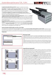
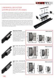
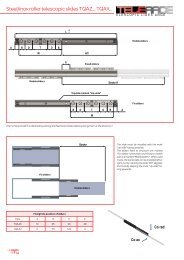
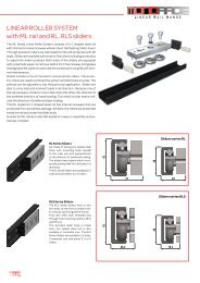
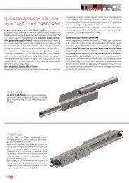
Roller telescopic slides TLR.., TLRX..<br />
T elescopic s lides R ANGE<br />
The TLR slides are the world’s only telescopic slides system which incorporated<br />
self-aligning feature to absorb parallelism errors of the mounting surfaces,<br />
when used in pairs.<br />
The TLR slides are designed for heavy duty High-Tech telescopic applications,<br />
with precise motorized movement, requiring constant smooth sliding performance<br />
with no play. Recommended for high frequency applications.<br />
The high performance is provide by use of double-row precision bearings, strong rails<br />
with hardened and honed raceways, fixed to a rigid intermediate S-shaped steel plate, assuring<br />
high load capacities and low flexion at even fully extended position.<br />
The TLR slides guarantee maintenance free operation, thanks to strong raceway wipers<br />
and longitudinal seals for dust and impurity protection. An integrated lubed for-life greasing<br />
system, assuring a constant thin layer of lubrication on the raceway surfaces, for a long<br />
operation period.<br />
TLR system offers unique possibilities and benefits for all kind of automation applications<br />
with variable strokes, for which a ball-cage slide often has ball-cage creeping problems, i.e.<br />
friction problems to reach full extension, as ball-cage is forced out to end position, instead<br />
of rolling.<br />
TLRX slides for corrosive ambients<br />
For corrosive ambients is available TLRX, with all components and intermediate element in stainless steel INOX, except the rails, which have T<br />
<strong>RACE</strong>-NOX anti-corrosion treatment; a oxidation treatment and impregnation in hot oil, to offer a good corrosion resistance.<br />
Extension<br />
The TLR slides allow for an extension equal to the closed slide plus a small constant.<br />
The extension is obtained by movement of the intermediate element and the lower rail, while<br />
the upper rail is fixed to structure.<br />
As it can be seen on left figure, the movement of the lower rail is more than the upper rail, due<br />
to optimizing of load capacity and the fact that the rollers are positioned on the intermediate<br />
element to offer max load capacity in this position. Hereby the TLR slides are asymmetric,<br />
so the slides must be ordered as left side slide TLRS and right side slide TLRD and when installed<br />
the product code must be on top side.<br />
The load capacities are all indicated per single rail, with centered load position, equal to half<br />
the rail in extended position.<br />
Compensation<br />
Self-aligning capacity<br />
When TLR slides are used in pairs, they offer the possibility to absorb minor structural errors<br />
or non-precise installation, which otherwise would much increase the required force for<br />
moving the mobile part, in both extending and closing direction. A typical problem for ballcage<br />
telescopic slides.<br />
Using a pair of self-aligning TLR slides, smooth low friction movement is assured, along with<br />
a more easy installation and/or less precise workings of structure, i.e. cost savings. The selfaligning<br />
feature is obtained by having a combination of floating rollers and guiding rollers in<br />
the TLR..A. i.e. allowing for a minor rotation of the rails, maintaining the preload in both upper<br />
and lower rails of the TLR..A slide.<br />
The suffix A in TLR..A, indicates “Aligning” The concept is well illustrated in the <strong>catalogue</strong> section<br />
MONO<strong>RACE</strong> , for which the base components have their origin.<br />
To be noted that the rotation of the TLR..A slide hereby changes the nominal value of 18,6mm<br />
to 17,2mmm ( S min) – 19,0mm ( S max) while compensating dimensional errors on mobile<br />
structure or distance errors between the two lateral sides of fixed structure, for which the<br />
upper rails are fixed to. Herewith avoiding binding-problems, with would much increase friction<br />
force, with consequent reduced load capacity and expected life-time.<br />
The TLR..A is in <strong>general</strong> always used in pair with a standard TLR, to assure good lateral stability.<br />
However good self-aligning can also be obtained for movement of vertical panels, with<br />
use of TLR..A at top to absorb some mis-alignment, and with some retainer guidance at lower<br />
part. Please refer to page 70, for further information.<br />
46