general catalogue - T RACE SpA
general catalogue - T RACE SpA general catalogue - T RACE SpA
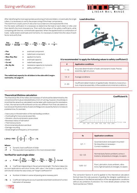
Sizing verification L INEAR R AIL R ANGE After identifying the most appropriate positioning of rails and sliders, or eventually the single rollers, it is necessary to verify the proper sizing of the linear components. This both from a static point of view and in accordance to the expected life-time. For the static verification it is necessary to determine the load on each slider or roller, and then identify the most stressed one. Then verify the values of the safety coefficients, while comparing with the max. nominal load capacities. When the applied load is a combination of loads; radial and/or axial loads and moments, it is necessary to determine the value of each factor and verify that: Load direction Mz Co rad Pax Co ax Prad Mex Mey Mez + + + + = 1 The radial load capacity for all sliders is the side with 2 engraved marks, ref. page 31. It is recommended to apply the following values to safety coefficient Z: Z 1 - 1,5 Application conditions Accurate determination of static and dynamic loads. Precise assembly, tight structure. 1,5 - 2 Avarage conditions 2 - 3,5 Insufficient determination of applied loads. Vibrations, loose structure. Imprecise assembly. Unfavourable einvironmental conditions. Theoretical lifetime calculation The theoretical life of the rollers and raceways of rail should be determined by the conventional formula as indicated below in km of running, however, should keep in mind that the value thus calculated must be taken with caution just for orientation, in fact, the real service life achieved can be very different from that calculated value, because the phenomena of wear and fatigue are caused by factors not easy to predetermine, for example: Coefficient fc • Inaccuracy in the estimation of the real loading condition • Overloading for inaccuracies assembly • Vibration, shock and dynamic pulse stress • Raceways status of lubrication • Thermal excursions • Environmental pollution and dust • Damage mounting • Stroke length and frequency of movement 3 L (Km) = 100 • C fc • P n • fa Where: - C = Dynamic load coefficient of slider - P = The equivalent load applied on the most stressed slider Verified for each single slider - P = ( ) ( P rad + Pax Mex Mey Mez Co ax + Mx + My + Mz • Co rad - fc = Coefficient depending on the actual stroke length. This factor takes into account applications with short stroke. With value 1 the stroke is superior to 2m, with shorter stroke the value is less, ref “Graph Coefficient Fc” ( fa 0,7 - 1 0,2 - 0,5 0,05 - 0,1 Application conditions Good lubrication and wipers mounted – No impurities on raceways – Correct installation Normal dusty factory ambient, some vibrations, temperature changes, no wipers Poor Lubrication, dusty ambient, vibrations, high temperature changes, no wipers - n = Number of sliders in same rail passing same raceway point - fa = Coefficient taking into account operational ambient and level of correct lubrication of raceways The correction factors fc and fa applied to the theoretical calculation formula have the sole purpose of guiding the designer qualitatively on the influence in the lifetime estimation of the real application conditions without any pretense of precision. For more details please contact the Technical Service T RACE. 38
Materials and treatments The MR and ML rails are both made from high precision cold drawn profiles, produced from specific carbon steel to provide high dept hardness, by nitriding hardening treatment. This innovative process is called T-NOX, and is developed by T RACE to assure high hardness, low wear and a high resistance to corrosion. This chemical heat treatment is conducted in three phases: 1) High depth nitriding 2) Black oxidation 3) Impregnation with corrosion inhibitors and mineral oil. The T NOX treatment is done on the complete rail surfaces, to also provide high corrosion protection on the raceways. Rails Material Treatments MR Series Steel for nitriding nitriding ML Series Steel for nitriding nitriding LAZ Series Steel Zinc plating LAX Series Stainless steel inox AISI 303 no The sliders use different materials according to below table Material Slider R. Series R.T, R.S Series RL, RLS Series PAZ Series R.SX Series PAX Series Slider body Zinc plated steel Zinc plated steel Zinc plated steel Zinc plated steel Stainless steel inox AISI 304 Lateral seals Polycarbonate no no no no no Wipers Polycarbonate elastomer Polycarbonate elastomer Polycarbonate elastomer no Polycarbonate elastomer no Pre-oiled sponge Sintetic fibre with bearing oil no Sintetic fibre with bearing oil no Screws Bright zinc plated steel Stainless steel inox Pins and spring washer Spring steel no Stainless steel inox no Washer Hardened steel Stainless steel inox AISI 440C Bearing seals Neopren Zinc plated steel Neopren Bearing cage Polyamide Zinc plated steel Polyamide Working temperature The operation temperature for sliders are -30° / +130° Celsius, for which max, temperature is limited by the 2RS seals. For the sliders RL. and PAZ, with 2Z seals the max operation temperature is 170° . On request special greased rollers can be supplied for higher/lower temperature. 39
- Page 1 and 2: T elescopic s lides R ANGE L INEAR
- Page 3 and 4: T RACE T RACE is a young and dynami
- Page 5 and 6: T elescopic s lides R ANGE Index TE
- Page 7 and 8: Monorace RANGE 28 18 43 MR rails wi
- Page 9 and 10: Sliders are available with either 3
- Page 11 and 12: 3 Rollers slider for R. series D C
- Page 13 and 14: R.T sliders for MR rails 3 Rollers
- Page 15 and 16: R.S and R.SX sliders for MR Rotatin
- Page 17 and 18: ML rails Lenght L (mm) 40 PITCH 80
- Page 19 and 20: RL sliders for ML rails Guiding sli
- Page 21 and 22: PAZ and PAX sliders 30 n°2 holes M
- Page 23 and 24: R. rollers for MR, FXR rails Roller
- Page 25 and 26: P. rollers for LA rails M The rolle
- Page 27 and 28: FXR rails The rail is made from spe
- Page 29 and 30: L INEAR R AIL R ANGE BSC curve rail
- Page 31 and 32: Examples of Mounting Arrangements a
- Page 33 and 34: Procedure for preload setting of sl
- Page 35 and 36: Thrust force The force required to
- Page 37: Assembly tolerances for two paralle
- Page 41 and 42: BALLrace range SF standard The seri
- Page 43 and 44: Ball-cage linear rail SF43, SFX43 W
- Page 45 and 46: 45 TLA.26 65 23 TLA.40 90 28,3 TQA.
- Page 47 and 48: Roller telescopic slides TLQ.., TLQ
- Page 49 and 50: Roller telescopic slides TLR.., TLR
- Page 51 and 52: Roller telescopic slides TLQ.., TLQ
- Page 53 and 54: Steel/inox roller telescopic slides
- Page 55 and 56: Steel/inox roller telescopic slides
- Page 57 and 58: TLS The TLS are full telescopic sli
- Page 59 and 60: Ball-cage telescopic slides TLS..,
- Page 61 and 62: Ball-cage telescopic slides TLS..D,
- Page 63 and 64: Ball-cage telescopic slides TSQ..,
- Page 65 and 66: Ball-cage telescopic slides TSQR..,
- Page 67 and 68: Ball-cage telescopic slides TSH..,
- Page 69 and 70: Synchronized telescopic slides TSH.
- Page 71 and 72: Semi-telescopic slides SR.., SRX..
- Page 73 and 74: Installation of telescopic slides M
- Page 75 and 76: Verification of load capacity Mz Co
- Page 77 and 78: Speed limitation The speed of the s
- Page 79 and 80: Versions and accessories SYNCHRONIS
- Page 81 and 82: Versions and accessories execution
- Page 84: T RACE S.p.A Via Eligio Brigatti 52
Sizing verification<br />
L INEAR R AIL R ANGE<br />
After identifying the most appropriate positioning of rails and sliders, or eventually the single<br />
rollers, it is necessary to verify the proper sizing of the linear components.<br />
This both from a static point of view and in accordance to the expected life-time.<br />
For the static verification it is necessary to determine the load on each slider or roller, and<br />
then identify the most stressed one. Then verify the values of the safety coefficients, while<br />
comparing with the max. nominal load capacities. When the applied load is a combination of<br />
loads; radial and/or axial loads and moments, it is necessary to determine the value of each<br />
factor and verify that:<br />
Load direction<br />
Mz<br />
Co rad<br />
Pax<br />
Co ax<br />
Prad Mex Mey Mez<br />
+ +<br />
+ +<br />
= 1<br />
The radial load capacity for all sliders is the side with 2 engraved<br />
marks, ref. page 31.<br />
It is recommended to apply the following values to safety coefficient Z:<br />
Z<br />
1 - 1,5<br />
Application conditions<br />
Accurate determination of static and dynamic loads. Precise<br />
assembly, tight structure.<br />
1,5 - 2 Avarage conditions<br />
2 - 3,5<br />
Insufficient determination of applied loads. Vibrations, loose structure.<br />
Imprecise assembly. Unfavourable einvironmental conditions.<br />
Theoretical lifetime calculation<br />
The theoretical life of the rollers and raceways of rail should be determined by the<br />
conventional formula as indicated below in km of running, however, should keep in<br />
mind that the value thus calculated must be taken with caution just for orientation,<br />
in fact, the real service life achieved can be very different from that calculated value,<br />
because the phenomena of wear and fatigue are caused by factors not easy to<br />
predetermine, for example:<br />
Coefficient fc<br />
• Inaccuracy in the estimation of the real loading condition<br />
• Overloading for inaccuracies assembly<br />
• Vibration, shock and dynamic pulse stress<br />
• Raceways status of lubrication<br />
• Thermal excursions<br />
• Environmental pollution and dust<br />
• Damage mounting<br />
• Stroke length and frequency of movement<br />
3<br />
L (Km) = 100 •<br />
C<br />
fc<br />
•<br />
P<br />
n<br />
• fa<br />
Where:<br />
- C = Dynamic load coefficient of slider<br />
- P = The equivalent load applied on the most stressed slider<br />
Verified for each single slider<br />
- P =<br />
( )<br />
(<br />
P rad + Pax Mex Mey Mez<br />
Co ax<br />
+ Mx<br />
+ My<br />
+ Mz<br />
• Co rad<br />
- fc = Coefficient depending on the actual stroke length. This factor takes into<br />
account applications with short stroke. With value 1 the stroke is superior to 2m,<br />
with shorter stroke the value is less, ref “Graph Coefficient Fc”<br />
(<br />
fa<br />
0,7 - 1<br />
0,2 - 0,5<br />
0,05 - 0,1<br />
Application conditions<br />
Good lubrication and wipers mounted –<br />
No impurities on raceways –<br />
Correct installation<br />
Normal dusty factory ambient, some vibrations,<br />
temperature changes, no wipers<br />
Poor Lubrication, dusty ambient, vibrations,<br />
high temperature changes, no wipers<br />
- n = Number of sliders in same rail passing same raceway point<br />
- fa = Coefficient taking into account operational ambient and level of correct<br />
lubrication of raceways<br />
The correction factors fc and fa applied to the theoretical calculation<br />
formula have the sole purpose of guiding the designer qualitatively on<br />
the influence in the lifetime estimation of the real application conditions<br />
without any pretense of precision. For more details please contact the<br />
Technical Service T <strong>RACE</strong>.<br />
38


