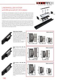
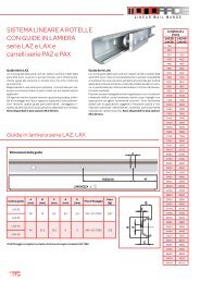
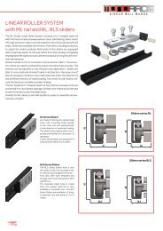
Construction tolerances The construction tolerances for the assembled dimensions of rails with their relative sliders are shown in below table. This too in relation to the rail mounting hole tolerances and mounting holes of the sliders. In particular, it is necessary to take into account the possibility that the axis of slider symmetry, may be slightly misaligned with the axis of L INEAR R AIL R ANGE symmetry of the rails. This mismatch may be larger in case of use of two sliders in same rail, of which one is postioned with load direction in opporsite load directions. This misalignments can be compensated while making the fixing holes sligthly larger on both fixed and mobile parts. F E D C G A B Rail type Slider type Tolerance A B C D E F G MRG18 R.G18 +0,15/-0,1 +0,2/-0,25 0/-0,1 +0,2/-0,2 +0,3/-0,35 0,2 0,8 R.28 +0,15/-0,1 +0,2/-0,25 0/-0,1 +0,2/-0,2 +0,3/-0,35 0,2 0,8 MR28 R.S28 +0,1/-0,15 +0,25/-0,25 0/-0,1 +0,2/-0,2 +0,35/-0,35 0,3 1,0 R.T28 +0,1/-0,15 +0,25/-0,25 0/-0,1 +0,2/-0,2 0,2 0,8 R.43 +0,15/-0,1 +0,2/-0,25 0/-0,1 +0,2/-0,2 +0,3/-0,35 0,2 0,8 MR43 R.S43 +0,1/-0,15 +0,25/-0,25 0/-0,1 +0,2/-0,2 +0,3/-0,35 0,3 1,0 R.T43 +0,1/-0,15 +0,25/-0,25 0/-0,1 +0,2/-0,2 0,2 0,8 ML28 RL28 +0,1/-0,15 +0,25/-0,25 0/-0,1 +0,2/-0,2 +0,35/-0,35 0,2 1,0 RLS28 +0,1/-0,15 +0,25/-0,25 0/-0,1 +0,2/-0,2 +0,35/-0,35 0,2 1,0 ML43 RL43 +0,1/-0,15 +0,25/-0,25 0/-0,1 +0,2/-0,2 +0,35/-0,35 0,2 1,0 RLS43 +0,1/-0,15 +0,25/-0,25 0/-0,1 +0,2/-0,2 +0,35/-0,35 0,2 1,0 LAZ26, LAX26 PAZ26, PAX26 +0,25/-0,25 +0,4/-0,4 0/-0,1 +0,3/-0,3 +0,5/-0,5 0,3 1,0 LAZ40, LAX40 PAZ40, PAX40 +0,25/-0,25 +0,4/-0,4 0/-0,1 +0,3/-0,3 +0,5/-0,5 0,3 1,0 Linear Precision The linear precision as the deviation of the sliders actual trajectory in relation to a theoretical straight line, is determined by the straightness of the surface in which the rail is fixed and the intrinsic precision of the rail. In reference to the linear precision of the sole rail, it is determined by the parallelism of the slider movement with respect to the two longitudinal planes of the rail, plan A and B. The values of A and B are shown in the below chart, as a function of the rail length = actual slider movement. The linear accuracy indicated in relation to plane A, is only achievable if the rail is fixed onto a perfectly straight/flat surfaces, using A all mounting holes. The linear accuracy indicated in relation to the side B is achievable only for rails with counterbored mounting holes, of series “L” , after having aligned the rail against a perfectly A straight reference side. In case rails with c’sunk mounting holes is used, the linear precision is related to the straightness of the structures mounting holes. The guide does not set free may not be perfectly straight (slightly arched on plan A) with no problem once clamped to a rigid structure. B B 36
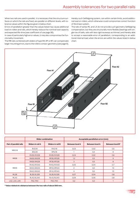
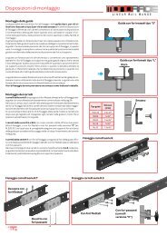
Assembly tolerances for two parallel rails When two rails are used in parallel, it is necessary that the structure surfaces on which the rails are fixed, are parallel on different levels, with tolerance values within the figures given in below chart. Errors of parallelism greater than the values listed may cause additional load on rollers and rails, which hereby reduce the nominal load capacity and expected life-time (see coefficient of use page 38). In case of particularly high error values, it may also compromise the functionality movement. The MR rails combined with sliders of type RA, RP or RF can compensate larger mounting errors, due to the rollers contact geometry (see page 9). Hereby such Selfaligning system, can within certain limits, avoid additional load on rollers, which otherwise could compromise correct function of the linear system. The rails of series ML and LA do not provide such geometry Selfaligning compensation, but they are structurally more flexible (bearings with single row of balls, rails with less rigid raceways as thinner) and hereby able to accept a reasonable error of parallelism, corresponding to an additional internal load, when the errors are within the values listed in below chart. Floor A1 Floor A2 Floor B1 Floor B2 Slider combination Acceptable parallelism error (mm) Pair of parallel rails Sliders in rail A Sliders in rail B Between level A Between level A Between level B* MRG18 RVG18 RVG18 0,03 0,02 0,5 RAG18 RPG18 1 0,4 8 RV28, RVS28 RV28, RVS28 0,04 0,02 0,6 MR28 RA28, RAS28 RP28, RPS28 1,2 0,5 9 RA28, RAS28 RF28, RFS28 3 0,5 8 RV43, RVS43 RV43, RVS43 0,05 0,04 0,7 MR43 RA43, RAS43 RP43, RPS43 2 0,6 10 RA43, RAS43 RF43, RFS43 4 0,6 10 ML28 RL28, RLS28 RL28, RLS28 0,07 0,04 0,8 ML43 RL43, RLS43 RL43, RLS43 0,09 0,06 0,8 LAZ, LAX, LAN PAZ, PAX PAZ, PAX 0,2 0,2 1 * Value related at a distance between the two rails of about 500 mm.. 37
- Page 1 and 2: T elescopic s lides R ANGE L INEAR
- Page 3 and 4: T RACE T RACE is a young and dynami
- Page 5 and 6: T elescopic s lides R ANGE Index TE
- Page 7 and 8: Monorace RANGE 28 18 43 MR rails wi
- Page 9 and 10: Sliders are available with either 3
- Page 11 and 12: 3 Rollers slider for R. series D C
- Page 13 and 14: R.T sliders for MR rails 3 Rollers
- Page 15 and 16: R.S and R.SX sliders for MR Rotatin
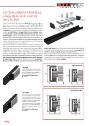
- Page 17 and 18: ML rails Lenght L (mm) 40 PITCH 80
- Page 19 and 20: RL sliders for ML rails Guiding sli
- Page 21 and 22: PAZ and PAX sliders 30 n°2 holes M
- Page 23 and 24: R. rollers for MR, FXR rails Roller
- Page 25 and 26: P. rollers for LA rails M The rolle
- Page 27 and 28: FXR rails The rail is made from spe
- Page 29 and 30: L INEAR R AIL R ANGE BSC curve rail
- Page 31 and 32: Examples of Mounting Arrangements a
- Page 33 and 34: Procedure for preload setting of sl
- Page 35: Thrust force The force required to
- Page 39 and 40: Materials and treatments The MR and
- Page 41 and 42: BALLrace range SF standard The seri
- Page 43 and 44: Ball-cage linear rail SF43, SFX43 W
- Page 45 and 46: 45 TLA.26 65 23 TLA.40 90 28,3 TQA.
- Page 47 and 48: Roller telescopic slides TLQ.., TLQ
- Page 49 and 50: Roller telescopic slides TLR.., TLR
- Page 51 and 52: Roller telescopic slides TLQ.., TLQ
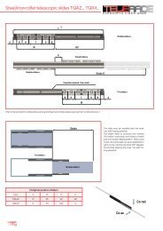
- Page 53 and 54: Steel/inox roller telescopic slides
- Page 55 and 56: Steel/inox roller telescopic slides
- Page 57 and 58: TLS The TLS are full telescopic sli
- Page 59 and 60: Ball-cage telescopic slides TLS..,
- Page 61 and 62: Ball-cage telescopic slides TLS..D,
- Page 63 and 64: Ball-cage telescopic slides TSQ..,
- Page 65 and 66: Ball-cage telescopic slides TSQR..,
- Page 67 and 68: Ball-cage telescopic slides TSH..,
- Page 69 and 70: Synchronized telescopic slides TSH.
- Page 71 and 72: Semi-telescopic slides SR.., SRX..
- Page 73 and 74: Installation of telescopic slides M
- Page 75 and 76: Verification of load capacity Mz Co
- Page 77 and 78: Speed limitation The speed of the s
- Page 79 and 80: Versions and accessories SYNCHRONIS
- Page 81 and 82: Versions and accessories execution
- Page 84: T RACE S.p.A Via Eligio Brigatti 52