general catalogue - T RACE SpA
general catalogue - T RACE SpA
general catalogue - T RACE SpA

Create successful ePaper yourself
Turn your PDF publications into a flip-book with our unique Google optimized e-Paper software.
T elescopic s lides R ANGE<br />
L INEAR R AIL R ANGE<br />
<strong>general</strong> <strong>catalogue</strong>
The writing of this <strong>catalogue</strong> was done with<br />
diligence, but it does not accept liability for any<br />
errors or omissions. We also reserve the right<br />
to make technical changes, recommend that<br />
you verify the update of the information here<br />
confronted with our engineering department.<br />
The reproduction of this <strong>catalogue</strong> is permitted<br />
only after our approval.<br />
Product Safety<br />
The products must be used following the<br />
instructions below. Given the variety of<br />
applications where the product can be used we<br />
are not able to assess whether a malfunction<br />
can cause damage to property or persons.<br />
The designer and the buyer are responsible<br />
for defining and implementing the safety<br />
instructions to enforce the end user.<br />
T <strong>RACE</strong> <strong>SpA</strong> , August 2013
T <strong>RACE</strong><br />
T <strong>RACE</strong> is a young and dynamic company, specialized in the design, manufacture and sales of new and<br />
innovative linear guides and telescopic slides. Although a newly established society, T <strong>RACE</strong> is composed<br />
of highly qualified people with comprehensive experience in the field of linear motion. T <strong>RACE</strong> has its own<br />
facilities in Italy and Germany, and a network of distributors in all major industrialized countries in the world, to<br />
ensure the presence of its products internationally.<br />
T <strong>RACE</strong> has the honour to present this new <strong>catalogue</strong>, in which the range of products has been further<br />
expanded with solutions, that are more responsive to the needs of its customers by pursuing the principles of<br />
continuous innovation of its product range, as a function of gained applied experience.<br />
The T <strong>RACE</strong> products are characterized by a strong originality for both the dimensions and geometric shapes<br />
and for the innovative production process. The C-shaped rails with internal raceways coupled with their roller<br />
sliders or ball cage sliders offer the best performance / size, available on the market. The innovative heat<br />
treatment of surface hardening, provides a high levels of wear resistance and excellent protection against<br />
corrosion due to post-treatment chemical oxidation, which also gives the original black color, the unique<br />
characteristics of the T <strong>RACE</strong> products.<br />
The linear rails and telescopic slides from T <strong>RACE</strong>, with their own design features, are particularly suitable<br />
in all applications, where the environmental conditions of use are critical and where the request is easily<br />
adaptable to mounting structures and ease of installation. The application areas are very diverse, ranging<br />
from CNC-machines and <strong>general</strong>-automation to civilian and military transport vehicles, medical equipment,<br />
civil construction, High-Tech furniture and countless other applications, where traditional re-circulating ball<br />
slides are not an adequate linear solution.<br />
The added value offered by T <strong>RACE</strong>, is the availability to adapt their standard products to specific applications,<br />
by developing customized versions for their clients, by providing its engineering service for the study, analysis<br />
and research of the optimal solution,- thanks also to its multidisciplinary experience gained in various sectors.<br />
The contents of the catalog are available online at www.t-race.com.<br />
Thanks to the collaboration with the company Traceparts, on the portal www.traceparts.com, all 3D models<br />
of products of this catalog are available for download in the native CAD format used by the designer.<br />
3
L INEAR R AIL R ANGE<br />
Index<br />
MONO<strong>RACE</strong> RANGE .................................................................... 6<br />
MR RAILS .......................................................................................10<br />
- R sliders...............................................................................11<br />
- R.T sliders........................................................................... 12<br />
- R.S sliders........................................................................... 14<br />
ML RAILS........................................................................................ 16<br />
- RL sliders............................................................................ 18<br />
- RLS sliders......................................................................... 19<br />
LA RAILS.........................................................................................20<br />
- PA sliders........................................................................... 21<br />
BSC CURVE RAILS .....................................................................29<br />
- RBS sliders.........................................................................29<br />
ROLLERS R.. FOR MR, FXR RAILS ......................................... 22<br />
ROLLERS L.. FOR ML RAILS .................................................... 24<br />
ROLLERS P.. FOR LA RAILS ..................................................... 25<br />
Linear Roller system<br />
Linear roller-slides selfalignment with high<br />
performance. DOUBLE row ball-bearings<br />
Rail series MR<br />
Slider series<br />
RV, RA, RP, RF<br />
RVT,RAT,RPT,RFT<br />
RVS, RAS, RPS, RFS / RVSX, RASX, RPSX<br />
Linear roller-slides standard system<br />
with single Row ball-bearings<br />
Rail series ML<br />
Slider series RL, RLS<br />
Pag. 8<br />
Pag. 16<br />
ASSEMBLY INSTRUCTIONS......................................................30<br />
SLIDER ORIENTATION .............................................................. 31<br />
PRELOAD SETTING OF SLIDERS ........................................... 32<br />
LUBRICATION OF <strong>RACE</strong>WAYS ............................................... 33<br />
SPLICED LONG RAILS ................................................................34<br />
THRUST FORCE ........................................................................... 35<br />
SPEED LIMITATIONS................................................................... 35<br />
CONSTRUCTION TOLERANCES............................................36<br />
ASSEMBLY TOLERANCES ........................................................ 37<br />
SIZING & LIFE- VERIFICATION................................................38<br />
MATERIALS AND TREATMENTS.............................................39<br />
WORKING TEMPERATURE .......................................................39<br />
Linear roller-slides rolled steel rails with<br />
roller-sliders<br />
Rail series LAZ, LAX<br />
Slider series PAZ, PAX<br />
CURVE RAILS ROLLER system<br />
Customized curve rails with<br />
roller sliders<br />
Pag. 20<br />
Rails series BCS<br />
Sliders series RBS<br />
Pag. 29<br />
F LEXIBLE R AIL R ANGE<br />
Index<br />
FXR RAILS .....................................................................................26<br />
- CONFIGURATIONS WITH FXR RAILS............................ 28<br />
flexible linear roller system<br />
Unique rail with 3 raceways<br />
for optimal configuration<br />
Rails series FXR<br />
Rollers series RCV, RCP, RCF<br />
Pag. 26<br />
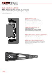
B ALL-CAGE L INEAR R ANGE<br />
Index<br />
BALL<strong>RACE</strong> RANGE ..................................................................... 40<br />
Ball-cage LINEAR system ............................................... 41<br />
- SF28 Ball-cage LINEAR rail ....................................42<br />
- SF43 Ball-cage LINEAR rail ....................................43<br />
ball-cage linear system<br />
Ball-cage linear rail<br />
Rails series SF, SFX<br />
4<br />
Pag. 40
T elescopic s lides R ANGE<br />
Index<br />
TELE<strong>RACE</strong> RANGE ......................................................................44<br />
INTRODUCTION TO ROLLER Telescopic slides ....46<br />
- TLR ROLLER Telescopic slides .............................48<br />
- TLQ ROLLER Telescopic slides .............................50<br />
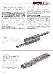
INTRODUCTION TO steel/inox telescopics ......... 52<br />
- TLAZ ROLLER Telescopic slides .......................... 53<br />
- TQAZ ROLLER Telescopic slides .........................54<br />
INTRODUCTION TO Ball-cage Telescopic slides .....56<br />
- TLS Ball-cage Telescopic slides .....................58<br />
- TLS.D Ball-cage Telescopic slides ............... 60<br />
- TSQ Ball-cage Telescopic slides ....................62<br />
- TSQR Ball-cage Telescopic slides .................64<br />
- TSH Ball-cage Telescopic slides ....................66<br />
- TSH..DSY Ball-cage Telescopic slides .........68<br />
- SR SEMI-Telescopic slides, Ball-cage ...........70<br />
INSTALLATION OF TELESCOPIC SLIDES........................... 72<br />
SIZING OF TELESCOPIC APPLICATIONS .......................... 74<br />
VERIFICATION OF LOAD CAPACITY..................................... 75<br />
LIFE-TIME VERIFICATION......................................................... 75<br />
CALCULATION OF FLEXION................................................... 76<br />
EXTENDING & CLOSING FORCE............................................ 76<br />
SPEED LIMITATION..................................................................... 77<br />
MATERIALS AND TREATMENTS............................................. 77<br />
OPERATING TEMPERATURE .................................................. 81<br />
Versions and accessories ............................................ 78<br />
- ADDITIONAL EXTERNAL stoppers ......................... 78<br />
- BLOCKING SYSTEM .......................................................... 78<br />
- synchronisation system .......................................79<br />
- synchronisation for tls, tlr ........................... 80<br />
- synchronisation for tsq, tlq ........................... 81<br />
REQUESTED TECHNICAL APPLICATION DATA .............. 82<br />
ROLLER TELESCOPIC slides<br />
Telescopic slides with<br />
double row ball-bearings<br />
Series TLR, TLRX<br />
Telescopic slides with variable<br />
stroke, and double row<br />
ball-bearings<br />
Series TLQ, TLQX<br />
Telescopic slides with<br />
ball-bearings, INOX (s/s)<br />
version also<br />
Series TLAZ, TLAX<br />
Telescopic slides with variable<br />
stroke, and ball-bearings,<br />
INOX (s/s) version also<br />
Series TQAZ, TQAX<br />
BALL-CAGE TELESCOPIC SLIDES<br />
Telescopic slides<br />
with ball-cage<br />
Series TLS, TLSX<br />
Pag. 48<br />
Pag. 50<br />
Pag. 53<br />
Pag. 54<br />
Pag. 58<br />
Compact telescopic slides<br />
with ball-cage.<br />
Series TSQ, TSQX<br />
TSQR, TSQRX<br />
Pag. 62/64<br />
Telescopic slides with ball-cage,<br />
syncronized version<br />
Series TSH, TSHX, TSH.DSY<br />
Pag. 66/68<br />
Semi-telescopic slides<br />
with ball-cage<br />
Series SR, SRX<br />
Pag. 70
L INEAR R AIL R ANGE<br />
Linear Roller system<br />
T <strong>RACE</strong>’s range of linear bearings are setting new standards due to its<br />
innovative design and technical concepts.<br />
The family MONO<strong>RACE</strong>, based on different C-shaped rails with a wide range<br />
of sliders, is offering unique linear solutions for all kinds of automation<br />
applications for many industries.<br />
T <strong>RACE</strong>’s system with roller sliders and internal raceways, offer the markets<br />
highest performing system, along with being size wise the most compact<br />
system.<br />
The rails series MR – ML are high precision cold-drawn profiles, made from a<br />
specific Casehardening steel alloy, to assure optimal surface hardening by<br />
nitrogen diffusion. In addition the treatment too provides a strong resistance<br />
against corrosion, meanwhile reducing the friction and wear, to assure a long<br />
life of the rail.<br />
The rails of series LA, are rolled steel profiles for simple applications. INOX<br />
version also available for severe conditions.<br />
The unique design of T <strong>RACE</strong>’s linear bearings, along with the products<br />
capability to fit non precise installation constructions, assures an optimal<br />
linear solution for the wide range of applications outside the typical machine<br />
tool market as: handling equipment, transport/military vehicles, office<br />
furniture, etc.<br />
6
Monorace RANGE<br />
28<br />
18<br />
43<br />
MR rails with<br />
R. series sliders.<br />
37 24 16,5<br />
43<br />
28<br />
MR rails with<br />
R.T series sliders.<br />
37,2 24,3<br />
28<br />
18<br />
43<br />
MR rails with<br />
R.S series sliders.<br />
28,20 18,30<br />
14,8<br />
ML rails with<br />
RL series sliders.<br />
ML rails with<br />
R.S series sliders.<br />
28<br />
28<br />
43<br />
43<br />
37 24<br />
28,2<br />
18,2<br />
40<br />
26<br />
LA rails with<br />
PA. series sliders.<br />
28,6<br />
22<br />
7
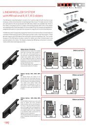
L INEAR R AIL R ANGE<br />
Linear Roller System<br />
with MR rail and R, R.T, R.S sliders<br />
The MR Series Linear Rail System consists of a C-section steel rail with internal convex<br />
raceways, where robust double row ball bearing rollers travel. The high precision rollers<br />
are lubricated for life and protected with 2RS seals. Sliders are available with three or<br />
five rollers, including eccentrics to adjust the bearing preload. Both ends of the sliders<br />
are equipped with polyamide wipers to remove debris from the raceway and grease impregnated<br />
felt wipers to lubricate the raceways for long life with minimal maintenance.<br />
The MR rail system is especially equiped for harsh environments where contamination is<br />
a problem. Most bearing systems utilize a groove that a roller or ball travel within. These<br />
grooves capture and hold debris that eventually cause the bearing to fail. The convex<br />
raceway of the MR Series provides a place for debris and other contaminates to be<br />
pushed aside by the rollers. This feature enables the MR Series to function in environments<br />
where other bearings quickly fail.<br />
Sliders Series: RV, RP, RA<br />
R Sliders Series are made of zinc plated<br />
steel with mounting holes parallel to<br />
the roller axis and perpendicular to<br />
the direction of preferred loading.The<br />
sliders have sealed rollers, axial wipers,<br />
and longitudinal seals for optimal<br />
protection of the internal parts and a<br />
sealing strip to prevent accidental tampering<br />
of the fixed rollers.<br />
The R Series Sliders are available in 3<br />
sizes and with either 3 or 5 rollers.<br />
43<br />
28<br />
18<br />
Sliders series R.<br />
37 24 16,5<br />
Sliders Series: RVT, RAT, RPT,<br />
RFT<br />
R.T Sliders Series are made of zinc<br />
plated steel with mounting holes perpendicular<br />
to the roller axis and parallel<br />
with the direction of preferred loading.<br />
The sliders have sealed rollers and<br />
axial wipers for protection of the internal<br />
parts. The R.T Series Sliders are<br />
available in 2 sizes and with either 3 or<br />
5 rollers<br />
43<br />
45<br />
28<br />
Sliders series R.T<br />
30<br />
37,2<br />
15<br />
10<br />
24,3<br />
Sliders Series: RVS, RAS, RPS,<br />
RFS<br />
The R.S Sliders Series have a very slim<br />
body to obtain the most compact<br />
slider possible, without sacrificing performance.<br />
They also offer both threaded<br />
and through hole mounting options.<br />
The standard slider body is made from<br />
zinc plated steel but is also available<br />
in all Stainless Steel construction for<br />
higher corrosion resistance.<br />
The R.S Series Sliders are available in 2<br />
sizes, 2 materials, and with either 3, 4 or<br />
5 rollers.<br />
43<br />
28,20<br />
28<br />
18,30<br />
Sliders series R.S<br />
18<br />
14,8<br />
8
Sliders are available with either 3 or 5 rollers. For the 3 roller version,<br />
the first and third roller are fixed, concentric rollers that run on the<br />
same raceway. The second roller is eccentric and runs on the opposite<br />
raceway.<br />
The eccentric feature is used to adjust the slider preload in the rail.<br />
For the 5 roller version, the two lateral and the central roller are fixed,<br />
and run on the same raceway.<br />
The second and fourth roller are eccentric and run on the opposite<br />
raceway. The eccentric feature is used to adjust the slider preload in<br />
the rail. Because one raceway contacts more rollers than the other<br />
raceway, the sliders have a preferred loading direction.<br />
The slider is marked with two small circular notches indicating the direction<br />
with the most rollers and direction of preferred loading. Care<br />
during assembly is required to ensure the maximum load capacity of<br />
the system is achieved.<br />
Roller loading position<br />
Slider with 3 rollers<br />
Slider with 5 rollers<br />
The rollers used in the sliders consist of two different geometries to<br />
achieve different levels of constraint within the linear rails Guiding<br />
Rollers (RCV, REV) contact the raceway at two points creating a well<br />
constrained rollers on the raceway. Floating Rollers (RCP, REP) engage<br />
only the peak of the raceway which constrains it radially but allows it to<br />
float in the axial direction between the two shoulders.<br />
By using different combinations of guiding and floating rollers, sliders<br />
with different performance characteristics are obtained. These combinations<br />
can be used to avoid the binding that can occur because of<br />
alignment problems when mounting two linear bearings in parallel.<br />
Guiding Sliders: By utilizing all guiding rollers RV, RTV, and RSV sliders<br />
are obtained, they are fully constrained and will support loads and moments<br />
in all directions with the greatest capacity in the radial direction.<br />
Roller contact points<br />
Guiding roller<br />
REV, RCV<br />
Floating roller<br />
REP, RCP<br />
Extra float roller<br />
REF, RCF<br />
Floating Sliders: By utilizing all floating rollers to construct RP, RSP,<br />
and RTP sliders are obtained, these sliders are able to carry full load in<br />
the radial direction and also float and rotate a small amount in the rail<br />
without affecting the preload or quality of the movement and without<br />
binding. Floating sliders are used in 2 rail systems to absorb parallelism<br />
errors in the mounting surfaces. For size 43 sliders, RF, RFT, and<br />
RFS sliders are available which allow even greater axial displacement.<br />
Rotating Sliders: By mixing guiding and floating rollers to construct<br />
RA, RSA, and RTA sliders are obtained, these sliders are able to carry<br />
full load in the radial direction and also rotate slightly without affecting<br />
the preload or quality of movement. These sliders also retain the ability<br />
to guide the payload as it travels. Rotating sliders are used in 2 rail<br />
systems to absorb angular errors in the mounting surfaces, that cause<br />
traditional bearings to bind.<br />
Slider contact points<br />
Combination: By combining a floating and rotating slider together in a<br />
2 rail system, the MR rail system can carry and guide a full payload while<br />
compensating for parallelism and angular errors in the rail mounting<br />
surfaces. These types of errors are often found when mounting to<br />
welded frames, structural Aluminum frames, sheet metal structures,<br />
etc. The self alignment capability can eliminate the need to machine<br />
the rail mounting surfaces.<br />
Guiding<br />
Slider<br />
RV, RVT, RVS<br />
Rotating<br />
Slider<br />
RA, RAT, RAS<br />
Floating<br />
Slider<br />
RP, RPT, RPS<br />
Slider with<br />
Extra Float<br />
RF, RFT, RFS<br />
Selfaligning combination<br />
Error on longitude parallelism<br />
Load guidance and<br />
Rotating movement<br />
Error on<br />
installation<br />
level<br />
Rotation<br />
slider<br />
RA.<br />
Floating<br />
slider<br />
RP. , RF.<br />
Floating and<br />
Rotating movement<br />
9
MR rails<br />
L INEAR R AIL R ANGE<br />
Code<br />
40<br />
A<br />
d<br />
A<br />
(mm)<br />
TECHNICAL DATA<br />
PITCH 80<br />
C<br />
S<br />
B<br />
(mm)<br />
D<br />
MR..L Counterbored holes<br />
(Example od order code: MR28L - 640)<br />
C<br />
(mm)<br />
S<br />
(mm)<br />
D<br />
(mm)<br />
d<br />
(mm)<br />
E<br />
(mm)<br />
d2<br />
(mm)<br />
Screw type<br />
MRG18S<br />
4,5 M4 DIN7991<br />
18 9,5 7,1 2,8<br />
MRG18L 9 5 1,9 M4 TORX *<br />
MR28S<br />
5,5 M5 DIN7991<br />
28 12 8 3<br />
MR28L 11 6 2 M5 TORX *<br />
MR43S<br />
8,5 M8 DIN7991<br />
43 18 13,2 5<br />
MR43L 18 10 3,2 M8 TORX *<br />
* Special flat-head TORX screws supplied with rails.<br />
Screw type<br />
B<br />
G<br />
(mm)<br />
E<br />
S<br />
(mm)<br />
L +2<br />
- 4<br />
V<br />
(mm)<br />
Tightening<br />
Torque<br />
M4 TORX M4 8 1,9 8 T20 3,5 Nm<br />
M5 TORX M5 10 2 10 T25 10Nm<br />
M8 TORX M8 16 3 16 T40 20Nm<br />
40<br />
d2<br />
90°<br />
MR..S Countersunk holes<br />
G<br />
S<br />
Weight<br />
(Kg/m)<br />
0,68<br />
1,25<br />
3,04<br />
MR Series Rails are made in 3 sizes 18mm, 28mm and 43mm<br />
with two types of mounting holes: MR .. L with counterbored<br />
mounting holes for special low head TORX mounting screws<br />
that are provided with the rail. MR .. S with countersunk<br />
mounting holes for UNI-standard ISO5933 fasteners.<br />
The rail has a “C” shaped cross-section with interior, convex<br />
raceways. The convex raceways are polished for smooth, low<br />
noise motion. The interior raceways are protected from accidental<br />
bumps and other damages, that can spoil the surface.<br />
The shape also protects the rollers from similar types of<br />
damages. MR Series Rails are made from carbon steel that<br />
is hardened through high depth nitriding. The rails are then<br />
treated with the innovative T<strong>RACE</strong>-NOX process, which delivers<br />
excellent corrosion resistance. This treatment is not a<br />
plating which can flake off but instead penetrates and alters<br />
the material surface. The result is a very hard and durable,<br />
corrosion resistance linear rail, that is black in color, due to<br />
the microimpregnation of oil and antioxidants.<br />
V<br />
Lenght L (mm)<br />
MRG18 MR28 MR43<br />
160<br />
240 240<br />
320 320<br />
400 400 400<br />
480 480 480<br />
560 560 560<br />
640 640 640<br />
720 720 720<br />
800 800 800<br />
880 880 880<br />
960 960 960<br />
1040 1040 1040<br />
1120 1120 1120<br />
1200 1200 1200<br />
1280 1280 1280<br />
1360 1360 1360<br />
1440 1440 1440<br />
1520 1520 1520<br />
1600 1600 1600<br />
1680 1680 1680<br />
1760 1760 1760<br />
1840 1840 1840<br />
1920 1920 1920<br />
2000 2000 2000<br />
2080 2080 2080<br />
2160 2160 2160<br />
2240 2240 2240<br />
2320 2320 2320<br />
2400 2400 2400<br />
2480 2480 2480<br />
2560 2560 2560<br />
2640 2640 2640<br />
2720 2720 2720<br />
2800 2800 2800<br />
2880 2880 2880<br />
2960 2960 2960<br />
3040 3040<br />
3120 3120<br />
3200 3200<br />
3280 3280<br />
3360 3360<br />
3440 3440<br />
3520 3520<br />
3600 3600<br />
3680 3680<br />
3760 3760<br />
3840 3840<br />
3920 3920<br />
4000 4000<br />
10
3 Rollers slider for R. series<br />
D<br />
C<br />
Mz<br />
R. sliders for MR rails<br />
RV Guiding slider dimensions<br />
B<br />
A<br />
n° 4<br />
holes M<br />
Co rad<br />
Cax<br />
Mx<br />
My<br />
H<br />
I<br />
C C C<br />
5 Rollers slider for R. series<br />
E<br />
M<br />
L<br />
B<br />
A<br />
n° 4 holes M<br />
G<br />
F<br />
Code<br />
RVG18-3<br />
Rail<br />
type<br />
E<br />
(mm)<br />
F<br />
(mm)<br />
G<br />
(mm)<br />
H<br />
(mm)<br />
I<br />
(mm)<br />
L<br />
(mm)<br />
M<br />
(mm)<br />
A<br />
(mm)<br />
B<br />
(mm)<br />
C<br />
(mm)<br />
Dynamic<br />
D Weight<br />
coeff.<br />
(mm) (g)<br />
C (N)<br />
Co rad<br />
(N)<br />
Co ax<br />
(N)<br />
Load capacity<br />
RPG18-3 78 70 20 52 75 3300 1600 0 0 0 15<br />
RAG18-3 3300 1600 460 3 9 15<br />
MRG18 18 16,5 9,5 7,1 4,8 16 M5<br />
RVG18-5<br />
4455 2160 1150 6 18 48<br />
Mx<br />
(Nm)<br />
My<br />
(Nm)<br />
Mz<br />
(Nm)<br />
3300 1600 690 3 9 15<br />
RPG18-5 120 112 20 120 4455 2160 0 0 0 48<br />
RAG18-5 4455 2160 690 6 18 48<br />
RV28-3<br />
6000 3200 1380 9 27 46<br />
RP28-3 102 94 35 78 240 6000 3200 0 0 0 46<br />
RA28-3 6000 3200 920 9 27 46<br />
MR28 28 24 12 8 9,7 25 M5<br />
RV28-5<br />
8100 4320 2300 18 46 120<br />
RP28-5 148 140 25 360 8100 4320 0 0 0 120<br />
RA28-5 8100 4320 1380 18 46 120<br />
RV43-3<br />
14200 7200 3210 32 92 155<br />
RP43-3 14200 7200 0 0 0 155<br />
147 136 55 114 730<br />
RA43-3 14200 7200 2080 32 92 155<br />
RF43-3 14200 7200 0 0 0 155<br />
MR43 43 37 18 13,2 14,8 40 M8<br />
RV43-5<br />
19170 9720 5350 64 165 418<br />
RP43-5 19170 9720 0 0 0 418<br />
218 207 40 1130<br />
RA43-5 19170 9720 3560 64 165 418<br />
RF43-5 19170 9720 0 0 0 418<br />
RA series – Rotating slider RP series – Floating slider RF series – Extra floating slider<br />
Series (+/-) a°<br />
RA18 1,5<br />
RA28 1,5<br />
RA43 1,5<br />
Series (+/-) a° F Min F Max<br />
RP18 1,5 16 17<br />
RP28 1,5 23,4 24,6<br />
RP43 1,5 36 38<br />
Series (+/-) a° F Min F Max<br />
RF43 1,5 36 40<br />
a° a°<br />
F Min<br />
F Max<br />
F Min<br />
F Max
R.T sliders for MR rails<br />
L INEAR R AIL R ANGE<br />
Sliders of series RVT, RAT, RPT , RFT, provide fixing holes parallel to the preferable radial load<br />
direction. As the slider body protrudes from rail level, the moving part can be resting on top of<br />
the linear system, while being fixed from above with threaded holes or from below with through<br />
passing holes.<br />
RVT Guiding slider dimensions<br />
d1<br />
N<br />
Slider type<br />
Threaded holes for<br />
top mounting<br />
Passing holes for bottom mounting, screw UNI 5931<br />
R.T28-3<br />
R.T28-5<br />
d1<br />
(mm)<br />
N<br />
(mm)<br />
Tipo vite<br />
d2<br />
(mm)<br />
S<br />
(mm)<br />
D<br />
(mm)<br />
M6 15 M5 Ø 5,5 5 Ø 9<br />
d2<br />
S<br />
R.T43-3<br />
R.T43-5<br />
M8 20 M6 Ø 6,5 6,5 Ø 11<br />
D<br />
The A and B versions differ only in the arrangement of the rollers providing maximum radial load capacity<br />
either toward or against the mounting surface. The preferential loading direction is marked by two circular<br />
notches. (Ordering code example: RVT28-3A or RVT28-3B) The slider body allows two methods of<br />
mounting. One method is to pass a fastener through the counterbored hole into the payload or to pass a<br />
fastener through the payload into the tapped hole at M.<br />
RVT Guiding slider dimensions<br />
H<br />
I<br />
Version A<br />
Version B<br />
Q<br />
E<br />
L<br />
G<br />
R<br />
F<br />
Rotation slider series RAT Floating slider series RPT Extra floating slider series RFT<br />
Series (+/-) a°<br />
RAT28 1,5<br />
RAT43 1,5<br />
Series (+/-) a° F Min F Max<br />
RPT28 1,5 23,7 24,9<br />
RPT43 1,5 36,2 38,2<br />
Series (+/-) a° F Min F Max<br />
RFT43 1,5 36,2 40,2<br />
a° a°<br />
F Min<br />
F Max<br />
F Min<br />
F Max<br />
12
R.T sliders for MR rails<br />
3 Rollers slider for R.T series – Version A 3 Rollers slider for R.T series – Version B<br />
C<br />
C<br />
B<br />
A<br />
B<br />
A<br />
5 Rollers slider for R.T series – Version A 5 Rollers slider for R.T series – Version A<br />
C<br />
C<br />
C<br />
C<br />
C<br />
C<br />
B<br />
B<br />
A<br />
A<br />
Code<br />
Rail<br />
E<br />
(mm)<br />
F<br />
(mm)<br />
G<br />
(mm)<br />
H<br />
(mm)<br />
I<br />
(mm)<br />
L<br />
(mm)<br />
N<br />
(mm)<br />
Q<br />
(mm)<br />
R<br />
(mm)<br />
A<br />
(mm)<br />
B<br />
(mm)<br />
Dynamic<br />
C Weight<br />
coeff.<br />
(mm) (g)<br />
C (N)<br />
Co rad<br />
(N)<br />
Load capacity<br />
Co ax<br />
(N)<br />
Mx<br />
(Nm)<br />
My<br />
(Nm)<br />
Mz<br />
(Nm)<br />
RVT28-3.<br />
6000 3200 1380 9 27 46<br />
RPT28-3. 102 94 36 280 6000 3200 0 0 0 46<br />
RAT28-3. 6000 3200 920 9 27 46<br />
MR28 28 24,3 12 8 10 30 15 32 19,5<br />
RVT28-5.<br />
8100 4320 2300 18 46 120<br />
RPT28-5. 148 140 27 430 8100 4320 0 0 0 120<br />
RAT28-5. 8100 4320 1380 18 46 120<br />
RVT43-3.<br />
14200 7200 3210 32 92 155<br />
RPT43-3. 14200 7200 0 0 0 155<br />
151 140 56 860<br />
RAT43-3. 14200 7200 2140 32 92 155<br />
RFT43-3. 14200 7200 0 0 0 155<br />
MR43 43 37,2 18 13,2 15 45 20 47 30<br />
RVT43-5.<br />
19170 9720 5350 64 165 418<br />
RPT43-5. 19170 9720 0 0 0 418<br />
235 224 42 1200<br />
RAT43-5. 19170 9720 3210 64 165 418<br />
RFT43-5. 19170 9720 0 0 0 418<br />
Mz<br />
Co rad<br />
Mx<br />
Example of order code.<br />
RVT28-3B : Guiding slider with 3 roller, version B<br />
Cax<br />
My<br />
13
R.S and R.SX sliders for MR rails<br />
L INEAR R AIL R ANGE<br />
Very compact slider, with slim strong slider body, for application with limited space. Performance like standard R-sliders including self aligning<br />
concept. Featuring extra long 4-roller version to optimize performance with only 1 slider, instead of 2 sliders.<br />
Guiding slider series RVS.<br />
Version R.S.-.. standard with<br />
threaded holes<br />
H<br />
Version R.S.-..C version<br />
with cylindrical holes<br />
I M M<br />
The sliders are available in standard version with threaded fixing<br />
holes R.S-.. and in version …C with through passing holes for<br />
inside fixing with standard cylindrical screws DIN912, with no<br />
interference with the rollers.<br />
Slider type M Type of fixing screws<br />
E<br />
D<br />
L<br />
D<br />
R.GS18-..<br />
M4<br />
R.GS18-..C Ø 4,5 M4 DIN912<br />
R.S.28-..<br />
M5<br />
G<br />
F<br />
R.S.28-..C Ø 5,5 M5 DIN912<br />
R.S.43-..<br />
M6<br />
R.S.43-..C Ø 6,5 M6 DIN912<br />
3 Rollers slider for R.S series 5 Rollers slider for R.S series<br />
n° 4 holes M<br />
C<br />
n° 4 holes M<br />
C<br />
B<br />
A<br />
B<br />
A<br />
n° 4 holes M<br />
C<br />
Long slider with 4 rollers R.S series<br />
INOX Versions<br />
The sliders in dimensions 28 and 43 are also<br />
available in INOX for version RVSX, RASX and<br />
RPSX. The rollers are hardened AISI 440C,<br />
while slider body AISI 304.<br />
The load capacities are identical to the<br />
standard version of RVS and RPS.<br />
B<br />
A<br />
The extra long slider body for 4-roller sliders<br />
R.S..-4L are made to offer an economical alternative<br />
for the many cases where 2 sliders<br />
are used, merely for proportional reasoning,<br />
rather than for load capacities.<br />
Also, option for very economical sliders for<br />
high Mz and My moment capacities.<br />
Mz<br />
Co rad<br />
Mx<br />
My<br />
Example of order codes.<br />
RVS28-3 : Guiding Slim-slider with 3 roller<br />
RPS43-4LC : Extra long rotation Slim-slider with 4 rollers<br />
and cylindrical fixing holes<br />
RVSX28-5: INOX guiding Slim-slider with 5 rollers<br />
14
R.S and R.SX sliders for MR<br />
Rotating slider RAS series Floating slider RPS series Extra floating slider RFS series<br />
Series (+/-) a°<br />
RAS18 1,5<br />
RAS28 1,5<br />
RAS43 1,5<br />
Series (+/-) a° F Min F Max<br />
RPS18 1,5 14,3 15,3<br />
RPS28 1,5 17,6 18,8<br />
RPS43 1,5 27,2 29,2<br />
Series (+/-) a° F Min F Max<br />
RFS43 1,5 27,2 31,2<br />
a° a°<br />
F Min F Max F Min F Max<br />
Code<br />
Rail<br />
Type<br />
E<br />
(mm)<br />
F<br />
(mm)<br />
G<br />
(mm)<br />
H<br />
(mm)<br />
I<br />
(mm)<br />
L<br />
(mm)<br />
A<br />
(mm)<br />
B<br />
(mm)<br />
C<br />
(mm)<br />
D<br />
(mm)<br />
Weight<br />
(g)<br />
Dynamic<br />
coeff.<br />
C (N)<br />
Co rad<br />
(N)<br />
Load capacity<br />
Co ax<br />
(N)<br />
Mx<br />
(Nm)<br />
My<br />
(Nm)<br />
Mz<br />
(Nm)<br />
RVGS18-3<br />
3300 1600 690 3 9 16<br />
RPGS18-3 81 73 21 8 75 3300 1600 0 0 0 16<br />
RAGS18-3 3300 1600 460 3 9 16<br />
RVGS18-5<br />
4455 2160 1150 6 19 49<br />
RPGS18-5 MRG18 18 14,7 9,5 7,1 3 15 110 102 50 8 120 4455 2160 0 0 0 49<br />
RAGS18-5 4455 2160 690 6 19 49<br />
RVGS18-4L<br />
3300 1600 920 6 27 78<br />
RPGS18-4L 158 150 98 8 125 3300 1600 0 0 0 78<br />
RAGS18-4L 3300 1600 460 6 27 78<br />
RVS.28-3.<br />
6000 3200 1380 9 30 52<br />
RPS.28-3. 114 106 32 10 140 6000 3200 0 0 0 52<br />
RAS.28-3. 6000 3200 920 9 30 52<br />
RVS.28-5.<br />
8100 4320 2300 18 52 130<br />
RPS.28-5. MR28 28 18,3 12 8 4 25 164 156 82 10 210 8100 4320 0 0 0 130<br />
RAS.28-5. 8100 4320 1380 18 52 130<br />
RVS.28-4L.<br />
6000 3200 1840 18 73 202<br />
RPS.28-4L. 208 200 126 10 230 6000 3200 0 0 0 202<br />
RAS.28-4L. 6000 3200 920 18 73 202<br />
RVS.43-3.<br />
14200 7200 3210 32 98 165<br />
RPS.43-3. 14200 7200 0 0 0 165<br />
164 153 46 16 440<br />
RAS.43-3. 14200 7200 1240 32 98 165<br />
RFS.43-3. 14200 7200 0 0 0 165<br />
RVS.43-5.<br />
19170 9720 5350 64 180 440<br />
RPS.43-5. 19170 9720 0 0 0 440<br />
MR43 43 28,2 18 13,2 6 40 241 230 124 16 670<br />
RAS.43-5. 19170 9720 3210 64 180 440<br />
RFS.43-5. 19170 9720 0 0 0 440<br />
RVS.43-4L.<br />
14200 7200 4280 64 257 698<br />
RPS.43-4L. 14200 7200 0 0 0 698<br />
311 300 194 16 750<br />
RAS.43-4L. 14200 7200 2140 64 257 698<br />
RFS.43-4L. 14200 7200 0 0 0 698<br />
15
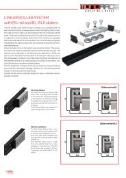
L INEAR R AIL R ANGE<br />
Linear Roller System<br />
with ML rail and RL, RLS sliders<br />
The ML Series Linear Roller System consists of a C shaped steel rail<br />
with internal concave raceways where robust ball bearing rollers travel.<br />
The high precision rollers are lubricated for life and protected with 2Z<br />
seals. Sliders are available with three or five rollers including eccentrics<br />
to adjust the slider’s preload. Both ends of the sliders are equipped<br />
with polyamide wipers to remove debris from the raceway and grease<br />
impregnated felt wipers to lubricate the raceways for long life with minimal<br />
maintenance.<br />
Sliders include a mix of concentric and eccentric rollers. The eccentric<br />
rollers are used to preload the system and eliminate any play. The<br />
preload can be adjusted to suit the particular application. Sliders are<br />
able to carry load and moment loads in all direction. Because one of<br />
the rail raceways contacts more rollers than the other, this direction is<br />
the prefered direction of radial loading. Two small circular marks indicate<br />
the direction of preferred slider loading.<br />
The ML Systems’s C shaped steel rail has internal raceways that are<br />
protected from accidental damage. Similarly, the rollers are protected<br />
inside the rail and under the slider body.<br />
Overall, the ML Series Linear Rail Systems is easy to assembly and extremely<br />
compact.<br />
RL Series Sliders<br />
are made of strong zinc plated steel<br />
body, with mounting holes parallel<br />
to the roller axis and perpendicular<br />
to the direction of preferred loading.<br />
The sliders have wipers which incorporate<br />
preoiled felt for lubrication of<br />
raceways.<br />
The RL Series Sliders are available in 2<br />
sizes and with either 3 or 5 rollers.<br />
43<br />
28<br />
Sliders series RL<br />
37<br />
24<br />
Sliders series RLS<br />
RLS Series Sliders<br />
The RLS Series Sliders have a very<br />
slim body, as the most compact slider,<br />
without sacrificing performance.<br />
They also offer both threaded and<br />
through hole mounting options (RLS<br />
and RLS..C).<br />
The standard slider body is made<br />
from zinc plated steel but is also<br />
available in complete inox. The RLS<br />
Series Sliders are available in 2 sizes,<br />
2 materials, and with either 3, 4 or 5<br />
rollers.<br />
43<br />
28<br />
28,2<br />
18,2<br />
16
ML rails<br />
Lenght L (mm)<br />
40<br />
PITCH 80<br />
40<br />
ML28<br />
ML43<br />
G<br />
Code<br />
A<br />
(mm)<br />
TECHNICAL DATA<br />
B<br />
(mm)<br />
C<br />
(mm)<br />
S<br />
(mm)<br />
D<br />
(mm)<br />
ML Series Rails are made in two sizes 28mm and 43mm with two<br />
types of mounting holes: ML .. L with counterbored mounting<br />
holes for special low head TORX mounting screws that are provided<br />
with the rail. ML .. S with countersunk mounting holes for<br />
UNI-standard ISO5933 fasteners. The rail has a “C” shaped crosssection<br />
with interior, concave raceways.<br />
The concave raceways are polished for smooth, low noise motion.<br />
The interior raceways are protected from accidental bumps<br />
d<br />
(mm)<br />
E<br />
(mm)<br />
d2<br />
(mm)<br />
Screw type<br />
ML28S<br />
5,5 M5 DIN7991<br />
28 11,5 8,2 3<br />
ML28L 11 6 2 M5 TORX*<br />
ML43S<br />
8,5 M8 DIN7991<br />
43 18,3 12,65 4,5<br />
ML43L 18 10 3,2 M8 TORX*<br />
S<br />
A<br />
d<br />
V<br />
C<br />
S<br />
E<br />
B<br />
D<br />
Counterbored holes ML..L<br />
(Code example: ML28L - 640)<br />
L +2<br />
- 4<br />
Screw type<br />
d2<br />
G<br />
(mm)<br />
S<br />
(mm)<br />
V<br />
(mm)<br />
Weight<br />
(kg/m)<br />
and other damage that can spoil the surface. The shape also protects<br />
the rollers from similar types of damage.<br />
ML Series Rails are made from carbon steel, that is hardened<br />
through high depth nitiriding.The rails are then treated with the innovative<br />
T<strong>RACE</strong>-NOX process which delivers excellent corrosion<br />
resistance. This treatment is not a plating which can flake off, but<br />
instead penetrates and alters the material surface.<br />
The result is a very hard and durable, corrosion resistant linear<br />
rail that is black in color, due to the microimpregnation of oil and<br />
antioxidants.<br />
1<br />
2,3<br />
Tightening<br />
Torque<br />
M5 TORX M5 10 2 10 T25 10Nm<br />
M8 TORX M8 16 3 16 T40 20Nm<br />
90°<br />
Countersunk holes ML..S<br />
240<br />
320<br />
400 400<br />
480 480<br />
560 560<br />
640 640<br />
720 720<br />
800 800<br />
880 880<br />
960 960<br />
1040 1040<br />
1120 1120<br />
1200 1200<br />
1280 1280<br />
1360 1360<br />
1440 1440<br />
1520 1520<br />
1600 1600<br />
1680 1680<br />
1760 1760<br />
1840 1840<br />
1920 1920<br />
2000 2000<br />
2080 2080<br />
2160 2160<br />
2240 2240<br />
2320 2320<br />
2400 2400<br />
2480 2480<br />
2560 2560<br />
2640 2640<br />
2720 2720<br />
2800 2800<br />
2880 2880<br />
2960 2960<br />
3040 3040<br />
3120 3120<br />
3200 3200<br />
3280 3280<br />
3360 3360<br />
3440 3440<br />
3520 3520<br />
3600 3600<br />
3680 3680<br />
3760 3760<br />
3840 3840<br />
3920 3920<br />
4000 4000<br />
17
RL sliders for ML rails<br />
L INEAR R AIL R ANGE<br />
The sliders of series RL offer a strong body with 4 fixing<br />
holes.<br />
3 Rollers slider RL<br />
D<br />
H<br />
I<br />
n° 4 holes M<br />
C<br />
E<br />
M<br />
L<br />
B<br />
A<br />
G<br />
5 Rollers slider RL<br />
F<br />
n° 4 holes M<br />
C C C<br />
B<br />
A<br />
Code<br />
Rail<br />
type<br />
E<br />
(mm)<br />
F<br />
(mm)<br />
G<br />
(mm)<br />
H<br />
(mm)<br />
I<br />
(mm)<br />
L<br />
(mm)<br />
M<br />
(mm)<br />
A<br />
(mm)<br />
B<br />
(mm)<br />
C<br />
(mm)<br />
D<br />
(mm)<br />
Dynamic<br />
Weight<br />
coeff.<br />
(g)<br />
C (N)<br />
Co rad<br />
(N)<br />
Co ax<br />
(N)<br />
Load capacity<br />
Mx<br />
(Nm)<br />
My<br />
(Nm)<br />
Mz<br />
(Nm)<br />
RL28-3<br />
105 97 35 78 220 4800 2000 750 5 13 27<br />
ML28 28 24 11,5 8,2 10 25 M5<br />
RL28-5 151 143 25 330 6480 2700 1250 10 25 75<br />
RL43-3<br />
152 143 55 114 700 11600 5000 1875 21 54 107<br />
ML43 43 37 18,3 12,65 15 40 M8<br />
RL43-5 226 215 40 1070 15660 6750 3125 41 95 285<br />
My<br />
Co rad<br />
Mx<br />
Cax<br />
Mz<br />
18
RL sliders for ML rails<br />
Guiding slider series RLS.<br />
Very compact slider, with thin strong slider body, for application<br />
with limited space. Performance like standard RL-sliders.<br />
Featuring extra long 4-roller version to optimize performance<br />
with only 1 slider, instead of 2 sliders.<br />
H<br />
I M M<br />
The sliders are available in standard version with threaded fixing<br />
holes RL.S-.. and in version …C with through passing holes<br />
for inside fixing with standard cylindrical screws DIN912, with<br />
no interference with the rollers.<br />
E<br />
D<br />
L<br />
D<br />
Slider type M Type of fixing screws<br />
G<br />
F<br />
Version RLS-.. standard with threaded holes<br />
Version RLS-..C version with cylindrical<br />
holes<br />
RLS28-..<br />
M5<br />
RLS28-..C Ø 5,5 M5 DIN912<br />
RLS43-..<br />
M6<br />
RLS43-..C Ø 6,5 M6 DIN912<br />
3 Rollers slider RLS. 5 Rollers slider RLS.<br />
n° 4 holes M<br />
C<br />
n° 4 holes M<br />
C<br />
B<br />
A<br />
B<br />
A<br />
n° 4 holes M<br />
C<br />
Long slider with 4 rollers RL.S series<br />
B<br />
A<br />
Code<br />
Rail<br />
type<br />
E<br />
(mm)<br />
F<br />
(mm)<br />
G<br />
(mm)<br />
H<br />
(mm)<br />
I<br />
(mm)<br />
L<br />
(mm)<br />
A<br />
(mm)<br />
B<br />
(mm)<br />
C<br />
(mm)<br />
D<br />
(mm)<br />
Weight<br />
(g)<br />
Dynamic<br />
coeff.<br />
C (N)<br />
Co rad<br />
(N)<br />
Co ax<br />
(N)<br />
Load capacity<br />
Mx<br />
(Nm)<br />
My<br />
(Nm)<br />
Mz<br />
(Nm)<br />
RLS28-3<br />
114 106 32 10 140 4800 2000 750 5 16 32<br />
RLS28-5 ML28 28 18,2 11,5 8,2 4 25 164 156 82 10 210 6480 2700 1250 10 28 82<br />
RLS28-4L 208 200 126 10 230 4800 2000 1000 10 39 126<br />
RLS43-3<br />
164 153 46 16 440 11600 5000 1875 19 57 115<br />
RLS43-5 ML43 43 28,2 18,3 12,65 6 40 241 230 124 16 670 15660 6750 3125 37 106 310<br />
RLS43-4L 311 300 194 16 750 11600 5000 2500 37 150 485<br />
19
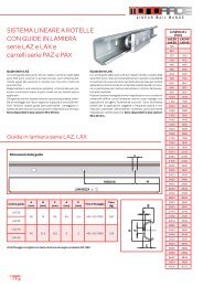
L INEAR R AIL R ANGE<br />
Roller linear system<br />
Sheet iron LAZ, LAX rails<br />
and PAZ, PAX sliders<br />
LAZ series rails<br />
LAZ series rails and PAZ series sliders are dimensionally identical<br />
to the LAX and PAX Series but are much lower in cost because<br />
they are made of Zinc plated steel.<br />
The LA series is a simple and functional solution for linear motion.<br />
The minimum space requirements, internal protected<br />
raceways, ease of assembly, and good load capacity makes this<br />
linear bearing system an excellent choice compared to other<br />
solutions available on the market.<br />
LAZ and LAX sheet iron rails<br />
Linear rail dimensions<br />
Rail code<br />
LAZ 26<br />
LAX 26<br />
LAZ 40<br />
LAX 40<br />
A<br />
(mm)<br />
B<br />
(mm)<br />
Suitable fixing screws of type ISO 7380<br />
C<br />
(mm)<br />
d<br />
(mm)<br />
LENGHT L +2<br />
- 4<br />
E<br />
(mm)<br />
Fixing screws<br />
Weight<br />
(kg)<br />
26 14 9,5 6,5 2,5 M5 - ISO 7380 0,67<br />
40 21,3 13,3 9 3 M8 - ISO 7380 1,55<br />
LAX series rails<br />
LAX series rails and PAX series sliders are constructed entirely<br />
of stainless steel and are a simple and functional solution for applications<br />
that require high corrosion resistance,.<br />
The rails and sliders bodies are made from 300 Series stainless<br />
with rollers made from 440C.<br />
These are particularly suitable for food processing, pharmaceutical,<br />
and medical applications or in difficult environments such<br />
as marine environments where there is exposure to highly corrosive<br />
agents.<br />
The slider is equipped with 3 rollers. The middle roller is eccentric<br />
and is used to adjust the slider preload.<br />
PITCH 80 40<br />
d<br />
A<br />
d<br />
E<br />
C<br />
B<br />
Lenght L (mm)<br />
LAZ 26<br />
LAX 26<br />
160<br />
240<br />
LAZ 40<br />
LAX 40<br />
320 320<br />
400 400<br />
480 480<br />
560 560<br />
640 640<br />
720 720<br />
800 800<br />
880 880<br />
960 960<br />
1040 1040<br />
1120 1120<br />
1200 1200<br />
1280 1280<br />
1360 1360<br />
1440 1440<br />
1520 1520<br />
1600 1600<br />
1680 1680<br />
1760 1760<br />
1840 1840<br />
1920 1920<br />
2000 2000<br />
2080 2080<br />
2160 2160<br />
2240 2240<br />
2320 2320<br />
2400 2400<br />
2480 2480<br />
2560 2560<br />
2640 2640<br />
2720 2720<br />
2800 2800<br />
2880 2880<br />
2960 2960<br />
3040 3040<br />
3120 3120<br />
3200 3200<br />
3280 3280<br />
3360 3360<br />
3440 3440<br />
3520 3520<br />
3600 3600<br />
3680 3680<br />
3760 3760<br />
3840 3840<br />
3920 3920<br />
4000 4000<br />
20
PAZ and PAX sliders<br />
30<br />
n°2 holes M5<br />
Sliders series<br />
PAZ26, PAX26<br />
with 3 rollers<br />
80<br />
3,7 4<br />
26<br />
25<br />
With LAZ<br />
and LAX rail<br />
22<br />
Mz<br />
Co rad<br />
Code Co rad (N) Co ax (N) Mx (Nm) My (Nm) Mz (Nm) Weight (g)<br />
PAZ26<br />
PAX26<br />
800 400 3 9 12 100<br />
Cax<br />
Mx<br />
My<br />
120<br />
n°4 holes M6<br />
23<br />
Sliders series<br />
PAZ40, PAX40<br />
with 3 rollers<br />
135<br />
5,3<br />
6<br />
40<br />
35<br />
with LAZ<br />
and LAX rail<br />
28,6<br />
Code Co rad (N) Co ax (N) Mx (Nm) My (Nm) Mz (Nm) Weight (g)<br />
PAZ40<br />
PAX40<br />
1600 800 9 23 32 430<br />
21
R. rollers for MR, FXR rails<br />
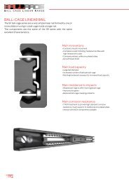
The ROLLE<strong>RACE</strong> rollers are designed around a double-row<br />
precision ball bearing to guarantee both high<br />
radial and axial load capacities. The rollers are protected<br />
by a double lip sealing system (2RS) to assure long<br />
lifetime, even in difficult environments. The integrated<br />
roller pivot has concentric or eccentric shape, to allow<br />
for preload setting in the different systems.<br />
The bearings are made to precision class DIN620 of<br />
core-hardened carbon steel. The rollers are available<br />
in series R.V with 2 contact points on the protruding<br />
raceways to obtain, a rigid guiding movement.<br />
The R.P has the rollers with some limited floating/compensation<br />
capacity, as only having one contact point at<br />
the central part of the raceways.<br />
The R.F rollers offer much more floating capacity, as<br />
one side is completly flat (only rollers in size 43/63) .<br />
The rollers of size 28 and 43 are also available in INOX<br />
stainless steel series R..X. All made from AISI440 steel,<br />
core hardened and ground, for applications in corrosive<br />
ambients.<br />
L INEAR R AIL R ANGE<br />
Only size<br />
63<br />
Guiding roller<br />
R.V<br />
Floating roller<br />
R.P<br />
Freely floating<br />
roller R.F<br />
Plain roller<br />
R.U<br />
R<br />
F<br />
L<br />
H<br />
δx<br />
δx<br />
δx<br />
22
R. rollers for MR, FXR rails<br />
Roller<br />
code<br />
Type<br />
E<br />
(mm)<br />
D C M G<br />
(mm) (mm) (mm) (mm)<br />
N<br />
Flat key<br />
A<br />
(mm)<br />
B<br />
(mm)<br />
P<br />
(mm)<br />
R<br />
(mm)<br />
F<br />
(mm)<br />
L<br />
(mm)<br />
Lateral<br />
H<br />
(mm) Version floating<br />
x<br />
For<br />
rail<br />
Dynamic<br />
coeff.<br />
C (N)<br />
Load capacity<br />
(N)<br />
Co rad<br />
Co ax<br />
Weight<br />
(g)<br />
RCV18G concentric 0<br />
REV18G eccentric 0,4<br />
RCP18G concentric 0<br />
REP18G eccentric 0,4<br />
13,2 7,0 4,6 1,1<br />
Allen key<br />
3<br />
6,8 M4 5,4 8,8<br />
11,4 guiding<br />
11,9 2,5 3,4 floating<br />
1<br />
(+/-0,5)<br />
MRG18 1650 800 230 10<br />
RCV28<br />
RCVX28<br />
REV28<br />
REVX28<br />
RCP28<br />
RCPX28<br />
REP28<br />
REPX28<br />
concentric 0<br />
eccentric 0,6<br />
concentric 0<br />
eccentric 0,6<br />
20,0<br />
9,0 6,3 1,75<br />
Allen key<br />
4<br />
10,8<br />
M5 7,0 13,9<br />
17,6 guiding<br />
17,9 3,0 4,8 floating<br />
1,2<br />
(+/-0,6)<br />
MR28 3000 1600 460 20<br />
RCU28 concentric 0<br />
REU28 eccentric 0,6<br />
17,8<br />
9,7 17,8 9 1,8 plain<br />
2<br />
(+/- 1)<br />
RCV43<br />
RCVX43<br />
REV43<br />
REVX43<br />
concentric 0<br />
eccentric 0,8<br />
30,8<br />
27 guiding<br />
RCP43<br />
RCPX43<br />
REP43<br />
REPX43<br />
concentric 0<br />
eccentric 0,8<br />
Allen key<br />
14,0 9,0 2,0 15,0 M8 10,5 21,3<br />
6<br />
30,4 27,2<br />
4,0 7,0 floating<br />
2<br />
(+/-1)<br />
MR43<br />
FXR<br />
7100 3600 1070 50<br />
RCF43 concentric 0<br />
REF43 eccentric 0,8<br />
9,0 7,0<br />
freely<br />
floating<br />
4<br />
(+3/-1)<br />
RCU43 concentric 0<br />
REU43 eccentric 0,8<br />
27,2 27,2 14 2 plain<br />
4,5<br />
(+3/-1,5)<br />
RCV63 concentric 0<br />
REV63 eccentric 1,2<br />
42,4 15,7 10,95 3,1<br />
Flat key 17<br />
Outer<br />
dim.<br />
for KMR<br />
63<br />
22,1 M10 18,8 38,4 guiding FXR 11200 6400 2000 80<br />
Position R refered to FXR rail is indicated at page 26<br />
23
L. rollers for ML rails<br />
L INEAR R AIL R ANGE<br />
The rollers of series L.V and P.Z are single row bearings with 2Z steel seals.<br />
The integrated roller pivot has concentric or eccentric shape, to allow for preload setting in<br />
the different systems.<br />
The bearings are made to precision class DIN620 of core-hardened carbon steel.<br />
The inner ball-retainer is too made of steel for high temperature applications to withstand<br />
high temperature.<br />
Roller<br />
code<br />
Type<br />
E<br />
(mm)<br />
D<br />
(mm)<br />
C<br />
(mm)<br />
M<br />
(mm)<br />
G<br />
(mm)<br />
N<br />
Flat key<br />
B<br />
(mm)<br />
R<br />
(mm)<br />
For<br />
rail<br />
Dynamic<br />
coeff.<br />
C (N)<br />
Load capacity<br />
(N)<br />
Co rad<br />
Co ax<br />
Weight<br />
(g)<br />
LCV28 concentric 0<br />
LEV28 eccentric 0,6<br />
LCV43 concentric 0<br />
LEV43 eccentric 0,8<br />
23,25 7,0 5,9 2,4<br />
35,7 11,0 9,4 3,85<br />
Flat key<br />
Outer dim. 10<br />
for KML 28<br />
Flat key<br />
Outer dim. 13<br />
for KML 43<br />
M5 14 ML28 2.400 1.000 250 20<br />
M8 22 ML43 5800 2500 625 50<br />
24
P. rollers for LA rails<br />
M<br />
The rollers series P.. Are also available in stainless steel INOX AISI440 hardened steel for<br />
corrosive ambients.<br />
The INOX rollers comes with 2RS seals and lubricated for life with mineral oil for alimentary<br />
application or low temperature applications.<br />
Roller<br />
code<br />
Type<br />
E<br />
(mm)<br />
D<br />
(mm)<br />
C<br />
(mm)<br />
M<br />
(mm)<br />
G<br />
(mm)<br />
N<br />
Flat key<br />
A<br />
(mm)<br />
B<br />
(mm)<br />
R<br />
(mm)<br />
For<br />
rail<br />
Dynamic<br />
coeff.<br />
C (N)<br />
Load capacity<br />
(N)<br />
Co rad<br />
Co ax<br />
Weight<br />
(g)<br />
PCZ26 concentric 0<br />
PEZ26 eccentric 0,6<br />
PCX26 concentric 0<br />
PEX26 eccentric 0,6<br />
20,3 6 8,5 5,5 Allen key 3 11,2 M5 13<br />
LAZ26<br />
LAX26<br />
900 400 148 10<br />
PCZ40 concentric 0<br />
PEZ40 eccentric 0,7<br />
PCX40 concentric 0<br />
PEX40 eccentric 0,7<br />
31,5 10 9,65 4,65 Allen key 5 15,0 M6 19,6<br />
LAZ40<br />
LAX40<br />
1800 800 296 40<br />
25
F LEXIBLE R AIL R ANGE<br />
Flexible linear system<br />
FLEX<strong>RACE</strong> a very flexible linear system with unique assembly possibilities.<br />
The FLEX<strong>RACE</strong> system provides an extremely versatile linear system, with great variety of rail /<br />
roller configurations for a wide range of applications. FLEX<strong>RACE</strong> is designed to be a strong and<br />
simple multitask linear system for larger handling and automation applications. It is a Low -cost,<br />
easy to assemble system, that offers smooth motion even on inaccurate surfaces.<br />
FXR rail with rollers<br />
Depending on space and capacity requirements, two dimensions of rollers are<br />
available, size 43 - 63. The standard rollers are guiding of type R.V, but with use<br />
of the floating-rollers R.P43 o r R.F43 and R.F63 a Selfaligning system is easily<br />
obtained.<br />
For corrosive ambients INOX rollers are also available in size 43.<br />
Fig. 1 Fig. 2 Fig. 3<br />
Rail with roller<br />
R.V63<br />
Possible roller positioning with FXR rail<br />
Roller type<br />
A<br />
(mm)<br />
B<br />
(mm)<br />
C<br />
(mm)<br />
For complete data and dimensions for rollers, please refer to page 23.<br />
D<br />
(mm)<br />
E<br />
(mm)<br />
F<br />
(mm)<br />
R.V43 22,85 0,8 27,9 33,73 38,78 22,85<br />
R.V63 24,8 1,71 29,85 39,41 44,46 24,8<br />
For R.F43=4mm<br />
Rail with roller<br />
R.V43<br />
Lateral floating 1mm<br />
(+/-0,5) only for R.P43<br />
Lateral floating<br />
Rail with guiding<br />
roller R.V<br />
Rail with floating<br />
roller R.P<br />
Rail with freely<br />
floating roller R.F<br />
26
FXR rails<br />
The rail is made from special carbon steel alloy to assure a good nitride hardening with our T <strong>RACE</strong>-NOX<br />
treatment. An innovative hardening technology applied to the linear rail products able to increase the<br />
hardness on the surface and in depth, enough to guarantee to support the typical Hertz’s stress in the point of<br />
contacts with the rollers, and to grant a strong resistance against corrosion, reducing the friction and the wear,<br />
for a long life of the rail.<br />
After nitride hardening the rails are processed with an oxidation treatment and subsequently a hot-oil<br />
impregnation to assure a nice black color and a high corrosion resistance. Now is also available the version<br />
FXR-P80 with holes pitches 80 mm, reccomended for high load application.<br />
+2<br />
- 4<br />
L (mm)<br />
400 560 720 880 1040 1200 1360 1520 1680 1840 2000 2160<br />
2320 2480 2640 2800 2960 3120 3280 3440 3600 3760 3920<br />
Weight (kg/m)<br />
2,09<br />
Roller positioning<br />
Co rad<br />
Co ax<br />
The roller must be correctly positioned with regards to load<br />
direction and also with sufficient number of rollers to assure<br />
requested load capacity and life-time.<br />
The load capacities are listed on page 23. Generally it is always<br />
preferable to position the rollers so the main loads are acting<br />
radially on the rollers, as highest load capacity for the rollers,<br />
i.e. Co rad. Load capacity is higher than axial load capacity Co<br />
ax, as the axial load is only acting on one raceway, compared to<br />
two raceways for radial loads.<br />
The rollers must be fixed to complete rigid and plan steel support<br />
and fixed with the below indicated tigthning torques for<br />
each type of rollers.<br />
While fixing screw of the rollers is maintained blocked with the<br />
key on the rear-end, each type of rollers has its own key/tool.<br />
When use of eccentric rollers, it is suggested to use a springwasher,<br />
between screw and roller, to facilitate the preload<br />
regulation before final tightening of roller.<br />
The preloading of the eccentric rollers are done, like explained<br />
for the sliders on page 32.<br />
Standard<br />
Allenkey<br />
Roller type<br />
Roller key<br />
Screw<br />
type<br />
Tightening torgue<br />
(Nm)<br />
R..18 Allenkey 3 M4 3<br />
R..28 Allenkey 4 M5 7<br />
R..43 Allenkey 6 M8 23<br />
R..63 KMR63 M10 38<br />
L..28 KLM28 M5 7<br />
L..43 KLM43 M8 23<br />
P..26 Allenkey 3 M5 7<br />
P..40 Allenkey 5 M6 11<br />
Lubrication of rails and rollers<br />
The correct lubrication of rails and rollers is very important to assure long life of the products, in<br />
case of high frequency applications. In such cases it is suggested to clean raceways and rollers<br />
and re-lubricate every approx. 100.000 cycles, in normal operation conditions.<br />
We suggest to use grease for high precision of type “Classe NLGI2 (ISO2137) .<br />
Special flatkey<br />
KM. KL.<br />
27
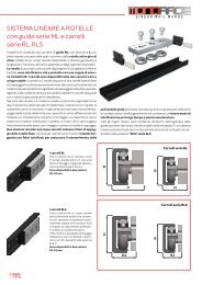
Possible configurations with FXR rails<br />
F LEXIBLE R AIL R ANGE<br />
The FXR rail allows for many different rail configurations for linear<br />
moments with 2 or more parallel rails fixed to plan or tubolar supports,<br />
on which rollers or carriers are running. With its unique 3-raceways,<br />
compact and space saving linear solutions can be obtained.<br />
The below illustrated configurations are all customized solutions<br />
T <strong>RACE</strong> have been offering its customers and are made to order.<br />
Naturally these solutions can also be made locally by end user, just<br />
buying the components, FXR rails and rollers.<br />
If requested T <strong>RACE</strong>’s Technical office can assist to assure correct<br />
dimensioning according to requested load/moment capacities.<br />
Main advantages are that linear solutions with high Mx moment<br />
capacities can easily be assembled. Solutions which too can substitute<br />
a monorail solution with parallel rails.<br />
Wide rail with inner carrier<br />
Wide rail with outer carrier<br />
Tubolar rail with external<br />
carrier for heavy loads/<br />
moments.<br />
Telescopic slide with rollers.<br />
Two elements moving<br />
to assure 100% extension.<br />
28
L INEAR R AIL R ANGE<br />
BSC curve rails<br />
The curve rails of series BSC are made to customers request, based on required radius,<br />
not inferior of 500mm, see below table.<br />
The curves radius is according to the requested angle a° with the limitation of lengths<br />
of one single rail-length. The rail is made from cold-drawn steel profiles with bright zincplating.<br />
The rails radial fixing points are also customized according to the below table.<br />
On the rail is running 3-roller sliders, which also is ordered on request, based on the radius.<br />
The rollers are single row bearings with 2Z seals.<br />
To assure a good lifetime of the system, we propose to grease regulary, based on the<br />
frequency, with grease of type “Class NLGI2” (ISO2137).<br />
Rail of series BSC<br />
Rail<br />
code<br />
Radius<br />
of curve<br />
R<br />
(mm)<br />
Lengths<br />
of rails<br />
(mm)<br />
Arch of<br />
curve<br />
a°<br />
Rails fixing holes<br />
position<br />
b°<br />
pitch<br />
c°<br />
M<br />
(mm)<br />
BSC28<br />
500 min<br />
3000<br />
max.<br />
on request Ø 5,5<br />
BSC43<br />
600 min<br />
4000<br />
max.<br />
on request Ø 6,5<br />
The fixing holes are for screws with cylindrical heads DIN.<br />
Slider series RBS<br />
Mz<br />
Co rad<br />
Cax<br />
Mx<br />
My<br />
Rail code<br />
A<br />
(mm)<br />
B<br />
(mm)<br />
C<br />
(mm)<br />
D<br />
(mm)<br />
F<br />
(mm)<br />
N<br />
(mm)<br />
H<br />
(mm)<br />
G<br />
(mm)<br />
E<br />
(mm)<br />
Load capacity (N)<br />
Co rad Co ax Mx My Mz<br />
RBS28-3 60 50 40 35 17,3 53,7 6,4 14,4 M5 800 400 2 6 8<br />
RBS43-3 90 80 60 58 24,7 90,7 12,2 21 M6 1600 800 6 18 24<br />
29
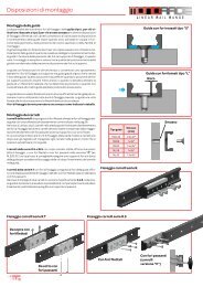
Assembly Instructions<br />
L INEAR R AIL R ANGE<br />
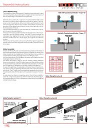
Linear Rail Mounting<br />
The availability of both countersunk (S-type) and counterbored (L-type)<br />
rail mounting holes allows optimization of alignment and orientation of<br />
the rails, depending on load direction and geometry.<br />
Generally the countersunk S-type rail is mounted with flathead screws<br />
and does not require special alignment, because the taper of the fastener<br />
and rail mounting hole, forces a rail into a specific position. Such<br />
rail mounting holes, allow for easy and fast rail installation, however the<br />
precision of the tapped hole placement in the mounting surface will affect<br />
the position of the rail.<br />
The counterbored holes in L-type rails allows for a small amount of lateral<br />
movement during installation.<br />
This type of mounting is preferred when the tapped holes in the mounting<br />
surface are not precisely placed. This type of mounting holes are<br />
necessary, when aligning the rail with an external reference surface, as<br />
the holes will allow the rail to move slightly, to sit against the reference<br />
surface.<br />
The rail must be secured to a structure sufficiently rigid to support the<br />
full load. The surface mounting holes should include a chamfer as shown<br />
in the table.<br />
Rail with Countersunk holes – Type-“S”<br />
Rail with Counterbored holes – Type –“L”<br />
Clearance<br />
Slider Assembly<br />
R sliders for MR and ML rails, have threaded holes parallel with the holes of<br />
the rail and aligned within the tolerance shown on page 36. In case of more<br />
sliders in same rail, the misalignment of the fixing holes of various sliders is<br />
compensated by making a bit larger holes on the fixing structure.<br />
It is recommended to only fully tighten the sliders mounting screws after<br />
installing all sliders in all the rails.<br />
This allows the sliders to align to the rail, avoiding creating additional<br />
stress on the sliders.R_S and RLS sliders have a slim slider body and allow<br />
for double slider fixing, with either threaded holes (standard) or a through<br />
hole, by adding a “C” designation to the part number (i.e. RLS28C-3).<br />
In case of through holes, it is advisable to drill some holes in the rail for access<br />
to the screws, for tightening after the sliders with screws are inserted<br />
into the rail. The RT sliders have mounting holes perpendicular to the rail<br />
mounting holes and offer the options of mounting from above or from below.<br />
In case where two sliders in respective version A and B, are installed in<br />
same rail, it might be necessary to shim the slider body thicknessupport,<br />
as eventual presence of minor misalignement (see tolerance on page 36)<br />
of slider body thickness.<br />
Rail<br />
type<br />
Chamfer<br />
(mm)<br />
MRG18 0.5x45°<br />
MR28 1x45°<br />
MR43 1.5x45°<br />
ML28 1x45°<br />
ML43 1.5x45°<br />
Slider fixing for series R.<br />
Chamfer<br />
Slider fixing for series R.T<br />
Slider fixing for series R.S<br />
Top-side fixing<br />
with threaded<br />
holes<br />
Bottom-side fixing<br />
with through passing holes<br />
Threaded holes<br />
Through passing<br />
holes<br />
(version “C”)<br />
30
Examples of Mounting Arrangements<br />
a) A pair of rails mounted on facing walls with S-type mounting<br />
holes, for fast installation. Combined with self-aligning RA sliders<br />
(rotating) and RP or RF sliders (floating), such linear system<br />
is capable of self adjusting for some mm of parallelism errors<br />
between the two walls, see also page 37 for further info.<br />
a)<br />
b) A pair of rails mounted to the same horizontal surface with<br />
“L” brackets to rotate the rails so they are loaded radially. The “L”<br />
type rails with counterbored holes are used to ensure full support<br />
of the rail on the horizontal surface. RVT sliders are fixed<br />
to a plate from above. Use of “L” type rails provides maximum<br />
rigidity of parallel rails.<br />
c) Rails are mounted on perpendicullar surfaces. The upper rail<br />
is of type S with countersunk<br />
holes for quick mounting and<br />
combined with a RAT slider to<br />
support the weight, but also MR43S/RAT43-3<br />
for allowing some rotational<br />
movement. The lower rail is<br />
with counterbored holes to<br />
allow rail adjustment against<br />
the vertical surface and is<br />
combinded with an RFS slider<br />
to allow for unlimited vertical<br />
compensation. The system<br />
simplifies installation and allows<br />
alignment of the rails on<br />
both the vertical plane and<br />
horizontal plane.<br />
MR43S/RA43-3<br />
MR43L/RVT43-3<br />
b)<br />
MR43S/RF43-3<br />
MR43L/RVT43-3<br />
d) Rails are mounted flat on a<br />
horizontal surface and loaded<br />
axially.<br />
The two rails are “L” type with<br />
counterbored mounting holes<br />
to allow proper rail alignment.<br />
One of the two rails should be<br />
pushed against a lateral support<br />
for precise alignment of<br />
the movement‘s linearity. The<br />
sliders are fixed to a carriage<br />
plate and the second rail is fastened<br />
in place while moving<br />
the carriage assembly along<br />
the full travel to ensure parallelism<br />
of the rails. The RV-sliders<br />
offer maximum stiffness<br />
and load capacity in the axial<br />
direction<br />
MR43L/RFS43-3<br />
c)<br />
MR43L/RV43-3<br />
d)<br />
MR43L/RV43-3<br />
Slider orientation<br />
Slider with 3 rollers<br />
P<br />
Mark on Slider<br />
Sliders with 3 and 5 rollers provide maximum load capacity in the radial<br />
direction with the greater number of rollers on the same raceway<br />
of the rail. The side is marked with two circular impressions on the<br />
slider body.<br />
For example, sliders carrying a load as shown in the picture below<br />
should be oriented with the marks opposite the load direction.<br />
The marks indicate where the maximum reaction force is available.<br />
P<br />
Slider positioning with<br />
overhanging loads<br />
Slider with 5 rollers<br />
P<br />
Mark on Slider<br />
31
Preload setting of sliders<br />
L INEAR R AIL R ANGE<br />
Preload setting of sliders series R.<br />
When the sliders are ordered mounted in rail, the preload setting is<br />
done in factory, with our regolation instruments to assure a standard<br />
light preload P1, to assure no play and with optimal smooth running.<br />
As there might be minor differences of internal raceway distance,<br />
between same type of rails, already preload set sliders should not be<br />
used for other rails. I.e. each slider must be preload set to each rail.<br />
When sliders are purchased separately from the rail, the preload setting<br />
is done according to below procedure, depending on whether<br />
the slider is type R_ or RL or LA.Preload setting is permitted for all<br />
sliders by the eccentric roller; one for 3 roller-sliders or two eccentric<br />
rollers in case of 5 roller-sliders. The adjustable eccentric rollers<br />
should be in contact with the opposite raceway of the fixed-rollers,<br />
which are all concentric rollers :<br />
1)<br />
Procedure for preload setting of sliders serie R.<br />
To make the preload setting, one must act on the top screw, tightening<br />
the eccentric wheel (only accessible screw left on the top cover<br />
band) and the pivot of the eccentric roller, - on the other side. 2 Allen<br />
keys are needed.<br />
1 - Verify that the raceways are clean, take the wipers off, to obtain<br />
a more sensitive feeling for correct preload setting and smooth running.<br />
2 - Tighten the top-screw, but not too much, to allow a firm turning of<br />
the eccentric bottom-pivot, maintaining the roller tight to slider body.<br />
3 - Turn the eccentric pivot so that the roller is roughly aligned with<br />
the concentric rollers or slightly in the opposite direction of the concentric<br />
rollers.<br />
4 - Block the rail on a stable support, so hands are free. Insert the<br />
slider into the rail. Insert the Allen key into the pivot, through the rail<br />
fixing hole. Turn the Allen key slightly, so that the eccentric roller is<br />
coming in light contact with the raceways, opposite the fixed rollers.<br />
During the rotation, accompany the top-screw while rotating in the<br />
same direction with second Allen key, in order to avoid any loosening<br />
or change in preload setting.<br />
5 - Move the slider along the whole rail length to find the part/point,<br />
where the slider moves with less friction/most oscillations. By pressing/pulling<br />
the slider ends, any oscillation is detected. If any oscillation/play<br />
is noted, the eccentric roller must be re-adjusted. Perfect<br />
preload setting is achieved, when the slider moves very smoothly and<br />
with no play at this point, with “widest” raceway distance.<br />
The checking for oscilation is not possible for type: RA rotation slider<br />
or floating sliders RP, RF.<br />
6 - Holding firm against the Allen key, engaged in eccentric pivot with<br />
one hand, while with other Allen key rotate and tighten the top-screw<br />
fastening the roller. WARNING! Do not lock or unlock the eccentric<br />
roller by turning the pivot, always only act on the top-screw for blocking/loosening<br />
the roller.<br />
7 - It’s possible to verify the amount of preload by slowly inserting the<br />
slider at the end. The inserting force Fi is proportional to the preload.<br />
In <strong>general</strong> a good setting correspond to the following min/max. forces<br />
shown in Table 6b.<br />
8 - Then make final roller/screw blocking using a torque wrench, to<br />
assure right closing torque (Mt) according to the values in Table 7b,<br />
while maintaining the Allen key in pivot, to prevent any change of<br />
preload setting.<br />
2)<br />
Fixed<br />
concentric<br />
roller<br />
3)<br />
4)<br />
5)<br />
Pivoting<br />
eccentric<br />
roller<br />
6)<br />
Fixed<br />
concentric<br />
roller<br />
For 5-roller sliders, the above steps are repeated for each of the<br />
two eccentric rollers. When adjusting the second eccentric roller, it<br />
is necessary to visually assure, that the roller has got in contact with<br />
the raceway, to hereby rotate in opposite direction, compared to the<br />
fixed rollers, when moving the slider. This can be seen through the<br />
rails fixing holes. The homogeneity of preload setting, between the<br />
two eccentric rollers, can be verified by simply inserting the slider<br />
with the other end, i.e. after turning the slider 180 degrees.<br />
WARNING! After preload setting, assure that slider is inserted with<br />
fixed rollers positioned in direction of applied load.<br />
In case the rail is already installed, so no longer accessable from behind,<br />
the preload is set outside the rail, by tentatively positioning of<br />
the eccentric roller in more steps, to finally obtain a smooth movement<br />
with no slider oscillation in the installed rail.<br />
32<br />
7)<br />
Slider type<br />
Fi - Inserting force<br />
min<br />
max<br />
R.18 0,5 N 2 N<br />
R.28 1 N 5 N<br />
R.43 2 N 10 N<br />
Slider type<br />
Mt - Tightning torque<br />
R.18 3 Nm<br />
R.28 9 Nm<br />
R.43 22 Nm
Procedure for preload setting of sliders serie<br />
PAZ, PAX .<br />
The PAZ/PAX sliders, like the R-sliders, have the preload setting done<br />
by adjustments of the central roller with eccentric pivot.<br />
The preload setting is done with 2 Allen keys and is similar to R-sliders,<br />
described on page 32.<br />
The closing torque Mt and inserting force for these sliders are shown<br />
in below tables.<br />
Preload setting of slider series PA.<br />
Slider type<br />
PAZ/PAX 26<br />
PAZ/PAX 40<br />
Mt - Tightning torque<br />
7 Nm<br />
23 Nm<br />
Slider type<br />
Fi - Inserting force<br />
min<br />
max<br />
PAZ/PAX 26 1 N 5 N<br />
PAZ/PAX 40 1 N 5 N<br />
Preload setting of slider series RL.<br />
Procedure for preload setting of sliders series RL.<br />
The RL sliders have unlike the R series, a special central square pivot<br />
accessable with a flat key inserted between slider body and eccentric<br />
roller.<br />
With this flat key, provided by T<strong>RACE</strong>, the correct preload setting is<br />
done following the concepts of adjustments described in page 32.<br />
While having the slider already inserted in rail.<br />
With this pivot concept, slider preload setting is too possible, while<br />
having both rail and slider already been installed.<br />
Regulation key KML<br />
Wipers for replacement series KT.<br />
Slider type<br />
RL28<br />
RL43<br />
Mt - Tightning torque<br />
7 Nm<br />
23 Nm<br />
Slider type<br />
Fi - Inserting force<br />
min<br />
max<br />
RL28 1 N 5 N<br />
RL43 2 N 10 N<br />
The flat key for preload<br />
setting of RL-sliders<br />
is supplied free of<br />
charge, on request. NB<br />
two type of keys, ref.<br />
below table.<br />
Slider type<br />
RL28<br />
RL43<br />
Lubrication of raceways<br />
Code for flat key<br />
KML28<br />
KML43<br />
All sliders, except PAZ and PAX series, are supplied with strong wipers with incorporated pre-oiled<br />
sponge, to provide a good greasing for a long period of operation. See table a right side for wiper codes<br />
for all sliders. The duration of this self-lubrication dependents on the employmental conditions and<br />
the level of environmental pollution. Usually under normal conditions, the self-lubricant wipers can last<br />
about 700 km, however they can easily be replaced with a kit of new wipers with sponge.<br />
The rollers are all, lubricated for life with grease of lithium type soap. The R_sliders have 2RS seals, while<br />
RL-sliders have metal 2Z seals.<br />
Lubrication is very important to assure a long operation life. For applications with high frequency and<br />
continuous movement, it is advisable to regularly clean the raceways and relubricate the sliders for<br />
every 100,000 cycles, depending on the operation environment. Grease of class NLGI2 (ISO 2137) is<br />
then recommended.<br />
Wiper codes<br />
Slider type<br />
KT- 18 R.18<br />
KT-28<br />
R.28, R. T28<br />
KT-43<br />
R.43, R. T43<br />
KTL-28<br />
RL28<br />
KTL-43<br />
RL43<br />
KTS-28<br />
R. S28<br />
KTS-43<br />
R. S43<br />
KTLS-28<br />
RLS28<br />
KTLS-43<br />
RLS43<br />
33
Spliced rails, composed of shorter preselected rails<br />
L INEAR R AIL R ANGE<br />
MR and ML rails can be supplied in longer lengths than offered<br />
in catalog, by splicing multiple rail segments together. These<br />
spliced rails must be ordered from the factory, while specifying<br />
the total length and the lengths of individual segments : “Example:<br />
MR43-6000 (4000 + 2000)” The spliced rail will be delivered<br />
in preselected segments length and with additional counterbored<br />
mounting holes added to the joining locations, in addtion<br />
to ground ends.<br />
The customer must add additional mounting holes in his structure<br />
for these additional holes at the joining location. End-screws<br />
for joining is too supplied free, same type as the standard screws<br />
for rails with cylindrical fixing holes.<br />
Alignment tool for spliced rails DAGA.<br />
To assure a correct<br />
alignment of the rail<br />
ends, an appropriate<br />
alignment tool can be<br />
purchased as a separate<br />
item. See drawing/table<br />
for product<br />
describtion and<br />
codes, at right side.<br />
Joining area for spliced rails<br />
PITCH 80<br />
A<br />
Additional<br />
holes at joint<br />
Rail type Joining screws Alignment tool A D d E<br />
MRG18 M4-TORX SP DAGA-MR18 16 9 5 1,9<br />
MR28 M5-TORX SP DAGA-MR28 16 11 6 2<br />
MR43 M8-TORX SP DAGA-MR43 22 18 10 3,2<br />
ML28 M5-TORX SP DAGA-ML28 16 11 6 2<br />
ML43 M8-TORX SP DAGA-ML43 22 18 10 3,2<br />
FXR M6-DIN 7984 DAGA-FXR 20 10,5 6,5 4,4<br />
d<br />
E<br />
D<br />
1)<br />
Installation instructions for rails composed of more lengths<br />
1) Begin by supporting the two rail segments at the splice location. Develop a support guide in the area of joining<br />
lengths. Insert the alignment tool DAGA from one end of the rail. Install the mounting screws including the<br />
two at the splice location, but do not fully tighten them, to allow for small rail movements.<br />
2) Place the alignment tool over the splice. Tighten the alignment tool screws to align the rail segments.<br />
Support<br />
3) Verify that rail mounting surfaces (back side and lateral side of the rail) are aligned. If not, it may be neccessary<br />
by use of shims, to maintain aligment after the mounting bolts are tightened and the alignment tool is<br />
removed.<br />
2)<br />
4) Tighten the bolts at the splice location by passing the Allen key through the holes in the alignment tool.<br />
Tighten the other mounting bolts in the rails.<br />
5) Loosen the alignment tool and remove it from one end.<br />
DAGA<br />
3) 4) 5)<br />
Shims<br />
34
Thrust force<br />
The force required to move a slider is contingent on several factors, which are summarized to each other<br />
in releation to the application. I.e. the actual load applied, the direction of the load, the preload setting of<br />
the slider, friction of wipers/lateral seals and bearing seals. In principle the slider, when preload in rail without<br />
a load applied, may require a thrust force of Fw, which is mainly due to the preload setting, than friction<br />
caused by wipers. Especially the friction generated by wipers/lateral seals/preoiled sponges tends to<br />
decrease after an initial period, as adapting their shapes the raceways. If removing the wipers, the thrust<br />
force Fo is then only based on the slider preload setting. The thrust<br />
force from slider preload setting may varie along the rail, due to minor<br />
parallellism tolerance of the rails internal raceways.<br />
The thrust force Ft of the slider with a radial load P applied, is approximately<br />
proportional to the load as a coefficient function of friction<br />
of the wheels, increased by the thrust force Fw from wipers and<br />
preload setting.<br />
Ft =(P x μ)+Fw<br />
In case that slider is without wipers the value Ft results by:<br />
Ft =(P x μ)+Fo<br />
The below table shows the indicative values of Fw and Fo of a minimum<br />
value and a maximum value, depending on the preload setting<br />
of the slider. The result of Ft simplified formula is reasonably valid for<br />
applied loads greater than 10% of the maximum permissible load.<br />
For lower loads the coefficient of friction is increased up to twice the<br />
original value.<br />
P<br />
Ft<br />
Slider type<br />
Fo<br />
Static friction of slider without load<br />
and without wipers<br />
Fw<br />
Static friction of slider without load<br />
and with wipers<br />
μ μ<br />
Friction coefficient of rollers<br />
R.18 from 0,2 N to 0,5 N from 1 N to 1,5 N 0,005<br />
R.28 from 0,5 N to 1,5 N from 2,5 N to 3,5 N 0,005<br />
R.43 from 1 N to 3,5 N from 6 N to 10 N 0,005<br />
RL/RLS/R.S28 from 0,5 N to 1,5 N from 2,5 N to 3,5 N 0,005<br />
RL/RLS/R.S43 from 1 N to 3,5 N from 6 N to 10 N 0,005<br />
PAZ-PAX from 0,1 N to 0,6 N 0,008<br />
Noise and speed<br />
T <strong>RACE</strong>’s roller sliders offer high operating speed up to 10m/s, with almost no noise, when compared to recirculating ball-sliders. The table on right side, shows the max.<br />
speed for different slider types. The R sliders with wipers and lateral seals, may emit a minor friction noise at no applied load, which however tends to decrease during<br />
use, as the parts adapt to the shapes of the raceways<br />
Slider type<br />
Max. speed<br />
R.18 5 m/s<br />
R.28 7 m/s<br />
R.43 10 m/s<br />
RL/RLS/R.S28<br />
7 m/s<br />
RL/RLS/R.S43<br />
10 m/s<br />
PAZ-PAX<br />
5 m/s<br />
35
Construction tolerances<br />
The construction tolerances for the assembled dimensions of rails with<br />
their relative sliders are shown in below table. This too in relation to the<br />
rail mounting hole tolerances and mounting holes of the sliders.<br />
In particular, it is necessary to take into account the possibility that<br />
the axis of slider symmetry, may be slightly misaligned with the axis of<br />
L INEAR R AIL R ANGE<br />
symmetry of the rails. This mismatch may be larger in case of use of two<br />
sliders in same rail, of which one is postioned with load direction in opporsite<br />
load directions.<br />
This misalignments can be compensated while making the fixing holes<br />
sligthly larger on both fixed and mobile parts.<br />
F<br />
E<br />
D<br />
C<br />
G<br />
A<br />
B<br />
Rail type<br />
Slider type<br />
Tolerance<br />
A B C D E F G<br />
MRG18 R.G18 +0,15/-0,1 +0,2/-0,25 0/-0,1 +0,2/-0,2 +0,3/-0,35 0,2 0,8<br />
R.28 +0,15/-0,1 +0,2/-0,25 0/-0,1 +0,2/-0,2 +0,3/-0,35 0,2 0,8<br />
MR28<br />
R.S28 +0,1/-0,15 +0,25/-0,25 0/-0,1 +0,2/-0,2 +0,35/-0,35 0,3 1,0<br />
R.T28 +0,1/-0,15 +0,25/-0,25 0/-0,1 +0,2/-0,2 0,2 0,8<br />
R.43 +0,15/-0,1 +0,2/-0,25 0/-0,1 +0,2/-0,2 +0,3/-0,35 0,2 0,8<br />
MR43<br />
R.S43 +0,1/-0,15 +0,25/-0,25 0/-0,1 +0,2/-0,2 +0,3/-0,35 0,3 1,0<br />
R.T43 +0,1/-0,15 +0,25/-0,25 0/-0,1 +0,2/-0,2 0,2 0,8<br />
ML28<br />
RL28 +0,1/-0,15 +0,25/-0,25 0/-0,1 +0,2/-0,2 +0,35/-0,35 0,2 1,0<br />
RLS28 +0,1/-0,15 +0,25/-0,25 0/-0,1 +0,2/-0,2 +0,35/-0,35 0,2 1,0<br />
ML43<br />
RL43 +0,1/-0,15 +0,25/-0,25 0/-0,1 +0,2/-0,2 +0,35/-0,35 0,2 1,0<br />
RLS43 +0,1/-0,15 +0,25/-0,25 0/-0,1 +0,2/-0,2 +0,35/-0,35 0,2 1,0<br />
LAZ26, LAX26 PAZ26, PAX26 +0,25/-0,25 +0,4/-0,4 0/-0,1 +0,3/-0,3 +0,5/-0,5 0,3 1,0<br />
LAZ40, LAX40 PAZ40, PAX40 +0,25/-0,25 +0,4/-0,4 0/-0,1 +0,3/-0,3 +0,5/-0,5 0,3 1,0<br />
Linear Precision<br />
The linear precision as the deviation of the sliders actual trajectory in relation to a theoretical straight line, is determined by the straightness of the surface in which the<br />
rail is fixed and the intrinsic precision of the rail. In reference to the linear precision of the sole rail, it is determined by the parallelism of the slider movement with respect<br />
to the two longitudinal planes of the rail, plan A and B.<br />
The values of A and B are shown in the below chart, as a function of<br />
the rail length = actual slider movement.<br />
The linear accuracy indicated in relation to plane A, is only achievable<br />
if the rail is fixed onto a perfectly straight/flat surfaces, using<br />
A<br />
all mounting holes. The linear accuracy indicated in relation to the<br />
side B is achievable only for rails with counterbored mounting holes,<br />
of series “L” , after having aligned the rail against a perfectly<br />
A<br />
straight reference side. In case rails with c’sunk mounting holes is<br />
used, the linear precision is related to the straightness of the structures<br />
mounting holes.<br />
The guide does not set free may not be perfectly straight (slightly<br />
arched on plan A) with no problem once clamped to a rigid structure.<br />
B<br />
B<br />
36
Assembly tolerances for two parallel rails<br />
When two rails are used in parallel, it is necessary that the structure surfaces<br />
on which the rails are fixed, are parallel on different levels, with tolerance<br />
values within the figures given in below chart.<br />
Errors of parallelism greater than the values listed may cause additional<br />
load on rollers and rails, which hereby reduce the nominal load capacity<br />
and expected life-time (see coefficient of use page 38).<br />
In case of particularly high error values, it may also compromise the functionality<br />
movement.<br />
The MR rails combined with sliders of type RA, RP or RF can compensate<br />
larger mounting errors, due to the rollers contact geometry (see page 9).<br />
Hereby such Selfaligning system, can within certain limits, avoid additional<br />
load on rollers, which otherwise could compromise correct function<br />
of the linear system.<br />
The rails of series ML and LA do not provide such geometry Selfaligning<br />
compensation, but they are structurally more flexible (bearings with single<br />
row of balls, rails with less rigid raceways as thinner) and hereby able<br />
to accept a reasonable error of parallelism, corresponding to an additional<br />
internal load, when the errors are within the values listed in below<br />
chart.<br />
Floor A1<br />
Floor A2<br />
Floor B1<br />
Floor B2<br />
Slider combination<br />
Acceptable parallelism error (mm)<br />
Pair of parallel rails Sliders in rail A Sliders in rail B Between level A Between level A Between level B*<br />
MRG18<br />
RVG18 RVG18 0,03 0,02 0,5<br />
RAG18 RPG18 1 0,4 8<br />
RV28, RVS28 RV28, RVS28 0,04 0,02 0,6<br />
MR28<br />
RA28, RAS28 RP28, RPS28 1,2 0,5 9<br />
RA28, RAS28 RF28, RFS28 3 0,5 8<br />
RV43, RVS43 RV43, RVS43 0,05 0,04 0,7<br />
MR43<br />
RA43, RAS43 RP43, RPS43 2 0,6 10<br />
RA43, RAS43 RF43, RFS43 4 0,6 10<br />
ML28 RL28, RLS28 RL28, RLS28 0,07 0,04 0,8<br />
ML43 RL43, RLS43 RL43, RLS43 0,09 0,06 0,8<br />
LAZ, LAX, LAN PAZ, PAX PAZ, PAX 0,2 0,2 1<br />
* Value related at a distance between the two rails of about 500 mm..<br />
37
Sizing verification<br />
L INEAR R AIL R ANGE<br />
After identifying the most appropriate positioning of rails and sliders, or eventually the single<br />
rollers, it is necessary to verify the proper sizing of the linear components.<br />
This both from a static point of view and in accordance to the expected life-time.<br />
For the static verification it is necessary to determine the load on each slider or roller, and<br />
then identify the most stressed one. Then verify the values of the safety coefficients, while<br />
comparing with the max. nominal load capacities. When the applied load is a combination of<br />
loads; radial and/or axial loads and moments, it is necessary to determine the value of each<br />
factor and verify that:<br />
Load direction<br />
Mz<br />
Co rad<br />
Pax<br />
Co ax<br />
Prad Mex Mey Mez<br />
+ +<br />
+ +<br />
= 1<br />
The radial load capacity for all sliders is the side with 2 engraved<br />
marks, ref. page 31.<br />
It is recommended to apply the following values to safety coefficient Z:<br />
Z<br />
1 - 1,5<br />
Application conditions<br />
Accurate determination of static and dynamic loads. Precise<br />
assembly, tight structure.<br />
1,5 - 2 Avarage conditions<br />
2 - 3,5<br />
Insufficient determination of applied loads. Vibrations, loose structure.<br />
Imprecise assembly. Unfavourable einvironmental conditions.<br />
Theoretical lifetime calculation<br />
The theoretical life of the rollers and raceways of rail should be determined by the<br />
conventional formula as indicated below in km of running, however, should keep in<br />
mind that the value thus calculated must be taken with caution just for orientation,<br />
in fact, the real service life achieved can be very different from that calculated value,<br />
because the phenomena of wear and fatigue are caused by factors not easy to<br />
predetermine, for example:<br />
Coefficient fc<br />
• Inaccuracy in the estimation of the real loading condition<br />
• Overloading for inaccuracies assembly<br />
• Vibration, shock and dynamic pulse stress<br />
• Raceways status of lubrication<br />
• Thermal excursions<br />
• Environmental pollution and dust<br />
• Damage mounting<br />
• Stroke length and frequency of movement<br />
3<br />
L (Km) = 100 •<br />
C<br />
fc<br />
•<br />
P<br />
n<br />
• fa<br />
Where:<br />
- C = Dynamic load coefficient of slider<br />
- P = The equivalent load applied on the most stressed slider<br />
Verified for each single slider<br />
- P =<br />
( )<br />
(<br />
P rad + Pax Mex Mey Mez<br />
Co ax<br />
+ Mx<br />
+ My<br />
+ Mz<br />
• Co rad<br />
- fc = Coefficient depending on the actual stroke length. This factor takes into<br />
account applications with short stroke. With value 1 the stroke is superior to 2m,<br />
with shorter stroke the value is less, ref “Graph Coefficient Fc”<br />
(<br />
fa<br />
0,7 - 1<br />
0,2 - 0,5<br />
0,05 - 0,1<br />
Application conditions<br />
Good lubrication and wipers mounted –<br />
No impurities on raceways –<br />
Correct installation<br />
Normal dusty factory ambient, some vibrations,<br />
temperature changes, no wipers<br />
Poor Lubrication, dusty ambient, vibrations,<br />
high temperature changes, no wipers<br />
- n = Number of sliders in same rail passing same raceway point<br />
- fa = Coefficient taking into account operational ambient and level of correct<br />
lubrication of raceways<br />
The correction factors fc and fa applied to the theoretical calculation<br />
formula have the sole purpose of guiding the designer qualitatively on<br />
the influence in the lifetime estimation of the real application conditions<br />
without any pretense of precision. For more details please contact the<br />
Technical Service T <strong>RACE</strong>.<br />
38
Materials and treatments<br />
The MR and ML rails are both made from high precision cold<br />
drawn profiles, produced from specific carbon steel to provide<br />
high dept hardness, by nitriding hardening treatment. This innovative<br />
process is called T-NOX, and is developed by T <strong>RACE</strong> to<br />
assure high hardness, low wear and a high resistance to corrosion.<br />
This chemical heat treatment is conducted in three phases:<br />
1) High depth nitriding<br />
2) Black oxidation<br />
3) Impregnation with corrosion inhibitors and mineral oil.<br />
The T NOX treatment is done on the complete rail surfaces, to<br />
also provide high corrosion protection on the raceways.<br />
Rails Material Treatments<br />
MR Series Steel for nitriding nitriding<br />
ML Series Steel for nitriding nitriding<br />
LAZ Series Steel Zinc plating<br />
LAX Series Stainless steel inox AISI 303 no<br />
The sliders use different materials according to below table<br />
Material<br />
Slider<br />
R. Series R.T, R.S Series RL, RLS Series PAZ Series R.SX Series PAX Series<br />
Slider body Zinc plated steel Zinc plated steel Zinc plated steel Zinc plated steel Stainless steel inox AISI 304<br />
Lateral seals Polycarbonate no no no no no<br />
Wipers<br />
Polycarbonate<br />
elastomer<br />
Polycarbonate<br />
elastomer<br />
Polycarbonate<br />
elastomer<br />
no<br />
Polycarbonate<br />
elastomer<br />
no<br />
Pre-oiled sponge Sintetic fibre with bearing oil no<br />
Sintetic fibre<br />
with bearing oil<br />
no<br />
Screws Bright zinc plated steel Stainless steel inox<br />
Pins and spring washer Spring steel no Stainless steel inox no<br />
Washer Hardened steel Stainless steel inox AISI 440C<br />
Bearing seals Neopren Zinc plated steel Neopren<br />
Bearing cage Polyamide Zinc plated steel Polyamide<br />
Working temperature<br />
The operation temperature for sliders are -30° / +130° Celsius, for which max, temperature is limited by the 2RS seals. For the sliders RL. and PAZ, with 2Z seals<br />
the max operation temperature is 170° . On request special greased rollers can be supplied for higher/lower temperature.<br />
39
B ALL-CAGE L INEAR R ANGE<br />
Ball-cage linear rail<br />
The SF ball-cage series are a very simple linear rail formed by one or<br />
more sliders moving in a ball-cage inside a longer rail.<br />
The components are the same of the SR series with the same<br />
excellent characteristics.<br />
Main innovations<br />
• Constant smooth movement<br />
• Complete overall nitritiding hardened profiles with<br />
high resistance to wear<br />
• Constant preload, unlike zinc plated slides<br />
• Smooth black finish<br />
Main load capacity<br />
• Large ball diameter<br />
• Increased number of balls per ball-cage<br />
• Nitriding hardened raceways for increased load capacity<br />
Main resistance to impacts<br />
• Shaped ball-cage to offer more rigid ball-cage<br />
• Improved stoppers<br />
• Reduced ball-cage creeping problems<br />
Main corrosion resistance<br />
• T NOX treatment to provide high standard corrosion<br />
resistance, much superior to traditional zinc plated slides<br />
• Version with INOX components available<br />
40
BALLrace range<br />
SF standard<br />
The series SF is conposed of a slider, moving inside the outer rail<br />
and ball-cage. The stroke is limited by the ball-cage and length of<br />
outer rail.<br />
Many standard versions are available.<br />
SF with double sliders<br />
in same ball-cage<br />
On request is provided 2 sliders moving along the same rail and ballcage.<br />
Version dedicated for applications with a long mobile part.<br />
The slider and rail versions are selected among the standard versions.<br />
SF with double slider<br />
in indipendent ball-cages<br />
On request is provided version with 2 sliders, each moving in its own<br />
independent ball-cage, to allow opposite movement direction, hence<br />
a 2 door sliding system.<br />
The slider and rail versions are selected among the standard versions.<br />
41
Ball-cage linear rail SF28, SFX28<br />
B ALL-CAGE L INEAR R ANGE<br />
W/2 Slider F<br />
Stroke H<br />
W/2<br />
a<br />
b<br />
b<br />
a<br />
Passo d<br />
c<br />
Rail L<br />
+2<br />
- 1<br />
= F+H+W<br />
28<br />
Holes for M5 c-sunk<br />
screw DIN7991<br />
13<br />
Series SF28<br />
6<br />
M5<br />
14,5<br />
Order code ex.:<br />
SF28-80-250-370<br />
Slider<br />
lenght F<br />
Stroke H<br />
Rail<br />
lenght L<br />
The SF ball-cage series are a linear rail with one or<br />
more sliders moving in a ball-cage, inside a longer<br />
rail. The components are the same as SR.<br />
The product code is obtained, by first selecting the<br />
slider length, then based on required stroke, is selected<br />
the rail length, according to : L = F+H+W.<br />
Where W is a constant of 40 mm for series SF28.<br />
The version SRX28 for high corrosion resistance,<br />
have all components in INOX, except the profiles.<br />
SXR28 has same dimensions and performance as<br />
SR28.<br />
11,5<br />
Slider<br />
Weight: 0,7 kg/m<br />
Rail<br />
Weight: 1 kg/m<br />
F<br />
(mm)<br />
a<br />
(mm)<br />
b<br />
(mm)<br />
n°<br />
holes<br />
C<br />
Dynamic<br />
Co rad<br />
(N)<br />
Co ax<br />
(N)<br />
Load capacity<br />
Mx<br />
(Nm)<br />
My<br />
(Nm)<br />
60 10 20 3 3672 3600 2280 26 23 36<br />
80 10 20 4 4896 4800 3040 35 41 64<br />
Mz<br />
(Nm)<br />
130 25 80 2 7956 7800 4940 57 107 169<br />
210 25 80 3 12852 12600 7980 93 279 441<br />
290 25 80 4 17748 17400 11020 128 533 841<br />
370 25 80 5 22644 22200 14060 163 867 1369<br />
450 25 80 6 27540 27000 17100 198 1283 2025<br />
Can be produced on request solutions with<br />
more sliders within the same ball-cage or<br />
with more sliders inside separate ball-cages.<br />
The sliders (F) and the rails (L) length<br />
could be selected among the standard versions.<br />
Mz<br />
Co rad<br />
L<br />
(mm)<br />
c<br />
(mm)<br />
d<br />
(mm)<br />
n°<br />
holes<br />
W<br />
(mm)<br />
130 25 80 2 40<br />
210 25 80 3 40<br />
290 25 80 4 40<br />
370 25 80 5 40<br />
450 25 80 6 40<br />
530 25 80 7 40<br />
610 25 80 8 40<br />
690 25 80 9 40<br />
770 25 80 10 40<br />
850 25 80 11 40<br />
930 25 80 12 40<br />
1010 25 80 13 40<br />
Cax<br />
Mx<br />
My<br />
1170 25 80 15 40<br />
1330 25 80 17 40<br />
1490 25 80 19 40<br />
1650 25 80 21 40<br />
42
Ball-cage linear rail SF43, SFX43<br />
W/2 Slider F<br />
Stroke H<br />
W/2<br />
a<br />
b<br />
b<br />
a<br />
Pitch d<br />
c<br />
+2<br />
Rail L - 1 = F+H+W<br />
43<br />
Holes for M8 c-sunk<br />
DIN7991<br />
22<br />
Series SF43<br />
11,5<br />
M8<br />
21<br />
Order code ex.:<br />
SF43-210-350-610<br />
Slider<br />
lenght F<br />
Stroke H<br />
Rail<br />
lenght L<br />
The SF ball-cage series are a linear rail with one or<br />
more sliders moving in a ball-cage, inside a longer<br />
rail. The components are the same as SR.<br />
The product code is obtained, by first selecting the<br />
slider length, then based on required stroke, is selected<br />
the rail length, according to : L = F+H+W.<br />
Where W is a constant of 50 mm for series SF43.<br />
The version SRX43 for high corrosion resistance,<br />
have all components in INOX, except the profiles.<br />
SXR43 has same dimensions and performance as<br />
SR43.<br />
18,30<br />
Slider<br />
Weight:1,8 kg/m<br />
Rail<br />
Weight: 2,4 kg/m<br />
F<br />
(mm)<br />
a<br />
(mm)<br />
b<br />
(mm)<br />
n°<br />
holes<br />
C<br />
Dynamic<br />
Co rad<br />
(N)<br />
Co ax<br />
(N)<br />
Load capacity<br />
Mx<br />
(Nm)<br />
My<br />
(Nm)<br />
Mz<br />
(Nm)<br />
L<br />
(mm)<br />
c<br />
(mm)<br />
d<br />
(mm)<br />
n°<br />
holes<br />
W<br />
(mm)<br />
290 25 80 4 50<br />
370 25 80 5 50<br />
130 25 80 2 15587 14300 9230 162 200 310<br />
210 25 80 3 25179 23100 14910 262 522 809<br />
290 25 80 4 34771 31900 20590 361 995 1542<br />
370 25 80 5 44363 40700 26270 461 1620 2510<br />
450 25 80 6 53955 49500 31950 561 2396 3713<br />
530 25 80 7 63547 58300 37630 660 3324 5150<br />
610 25 80 8 73139 67100 43310 760 4403 6822<br />
Can be produced on request solutions with more sliders within the same ball-cage or with more sliders<br />
inside separate ball-cages. The sliders (F) and the rails (L) length could be selected among the standard<br />
versions.<br />
450 25 80 6 50<br />
530 25 80 7 50<br />
610 25 80 8 50<br />
690 25 80 9 50<br />
770 25 80 10 50<br />
850 25 80 11 50<br />
930 25 80 12 50<br />
1010 25 80 13 50<br />
1170 25 80 15 50<br />
1330 25 80 17 50<br />
1490 25 80 19 50<br />
1650 25 80 21 50<br />
1810 25 80 23 50<br />
1970 25 80 25 50<br />
43
T elescopic s lides R ANGE<br />
roller telescopic slides<br />
The roller telescopic slides of series TLR and TLQ are designed for continous<br />
movements and for variable stroke, for both horizontal and vertical<br />
applications.<br />
The TLR series allow for unique compensation of misalignment, when<br />
mounted in pair, to hereby much reduce binding from minor installation<br />
error.<br />
These telescopic slides have incorporated wipers and pregreased sponge,<br />
to provide clean and lubricated raceways.<br />
The versions TLRX and TQAX offer high corrosion resistance, as all parts are<br />
made in INOX, except the rails, which come with T <strong>RACE</strong>-NOX innovative<br />
anti-corrosion treatment .<br />
Three section-dimensions are available : 18, 28 and 43mm .<br />
The roller telescopic slides of series TLA and TQA are available in two<br />
versions of material : The TLAZ and TQAZ with rolled zinkplated rails and<br />
rollers in hardened steel. The TLAZ and TQAX are fully made of INOX<br />
AISI 304 and the rollers in AISI440 for high corrosion resistance and for<br />
applications requiring only INOX components.<br />
This series are designed for applications with medium load capacity,<br />
requiring smooth and silent movement, at a lower price level.<br />
Two section-dimensions are available : 26 and 40mm.<br />
Ball-cage Telescopic slides<br />
The ball-cage telescopic slides of series TLS, TSQ and TSH are designed<br />
high load applications, requiring min. flexion.<br />
The semi-telescopic slides of series SR is the base component for<br />
mentioned telescopic slides .<br />
The optimized design and nitriding hardened raceways provide superior<br />
performance compared to traditional induction hardened and subsequent<br />
zinc plated raceways, which soon become un-stable as the zinc plating is<br />
consumed after short usage.<br />
The versions TLSX, TSQX, TSHX and SRX offer high corrosion resistance, as<br />
all parts are made in stainless steel INOX, except the rails, which come with<br />
T <strong>RACE</strong>-NOX innovative anti-corrosion treatment .<br />
Two section-dimensions are available : 28 and 43mm .<br />
44
45<br />
TLA.26<br />
65<br />
23<br />
TLA.40<br />
90<br />
28,3<br />
TQA.40<br />
40<br />
57,2<br />
TQA.26<br />
26<br />
44<br />
SR.43<br />
43<br />
22<br />
SR.28<br />
28<br />
13<br />
TSQ.43<br />
43<br />
44<br />
TSQ.28<br />
28<br />
26<br />
TLS.43<br />
120<br />
28<br />
TLS.28<br />
84<br />
17<br />
TLR.43<br />
116<br />
28,4<br />
TSH.43<br />
100<br />
47<br />
TLR.28<br />
80<br />
18,6<br />
TSH.28<br />
80<br />
28,5<br />
TLR.18<br />
52<br />
15,2<br />
TLQ.28<br />
28<br />
36,6<br />
TLQ.18<br />
18<br />
29,4<br />
TLQ.43<br />
43<br />
56,4<br />
telescopic slides
Roller telescopic slides TLR.., TLRX..<br />
T elescopic s lides R ANGE<br />
The TLR slides are the world’s only telescopic slides system which incorporated<br />
self-aligning feature to absorb parallelism errors of the mounting surfaces,<br />
when used in pairs.<br />
The TLR slides are designed for heavy duty High-Tech telescopic applications,<br />
with precise motorized movement, requiring constant smooth sliding performance<br />
with no play. Recommended for high frequency applications.<br />
The high performance is provide by use of double-row precision bearings, strong rails<br />
with hardened and honed raceways, fixed to a rigid intermediate S-shaped steel plate, assuring<br />
high load capacities and low flexion at even fully extended position.<br />
The TLR slides guarantee maintenance free operation, thanks to strong raceway wipers<br />
and longitudinal seals for dust and impurity protection. An integrated lubed for-life greasing<br />
system, assuring a constant thin layer of lubrication on the raceway surfaces, for a long<br />
operation period.<br />
TLR system offers unique possibilities and benefits for all kind of automation applications<br />
with variable strokes, for which a ball-cage slide often has ball-cage creeping problems, i.e.<br />
friction problems to reach full extension, as ball-cage is forced out to end position, instead<br />
of rolling.<br />
TLRX slides for corrosive ambients<br />
For corrosive ambients is available TLRX, with all components and intermediate element in stainless steel INOX, except the rails, which have T<br />
<strong>RACE</strong>-NOX anti-corrosion treatment; a oxidation treatment and impregnation in hot oil, to offer a good corrosion resistance.<br />
Extension<br />
The TLR slides allow for an extension equal to the closed slide plus a small constant.<br />
The extension is obtained by movement of the intermediate element and the lower rail, while<br />
the upper rail is fixed to structure.<br />
As it can be seen on left figure, the movement of the lower rail is more than the upper rail, due<br />
to optimizing of load capacity and the fact that the rollers are positioned on the intermediate<br />
element to offer max load capacity in this position. Hereby the TLR slides are asymmetric,<br />
so the slides must be ordered as left side slide TLRS and right side slide TLRD and when installed<br />
the product code must be on top side.<br />
The load capacities are all indicated per single rail, with centered load position, equal to half<br />
the rail in extended position.<br />
Compensation<br />
Self-aligning capacity<br />
When TLR slides are used in pairs, they offer the possibility to absorb minor structural errors<br />
or non-precise installation, which otherwise would much increase the required force for<br />
moving the mobile part, in both extending and closing direction. A typical problem for ballcage<br />
telescopic slides.<br />
Using a pair of self-aligning TLR slides, smooth low friction movement is assured, along with<br />
a more easy installation and/or less precise workings of structure, i.e. cost savings. The selfaligning<br />
feature is obtained by having a combination of floating rollers and guiding rollers in<br />
the TLR..A. i.e. allowing for a minor rotation of the rails, maintaining the preload in both upper<br />
and lower rails of the TLR..A slide.<br />
The suffix A in TLR..A, indicates “Aligning” The concept is well illustrated in the <strong>catalogue</strong> section<br />
MONO<strong>RACE</strong> , for which the base components have their origin.<br />
To be noted that the rotation of the TLR..A slide hereby changes the nominal value of 18,6mm<br />
to 17,2mmm ( S min) – 19,0mm ( S max) while compensating dimensional errors on mobile<br />
structure or distance errors between the two lateral sides of fixed structure, for which the<br />
upper rails are fixed to. Herewith avoiding binding-problems, with would much increase friction<br />
force, with consequent reduced load capacity and expected life-time.<br />
The TLR..A is in <strong>general</strong> always used in pair with a standard TLR, to assure good lateral stability.<br />
However good self-aligning can also be obtained for movement of vertical panels, with<br />
use of TLR..A at top to absorb some mis-alignment, and with some retainer guidance at lower<br />
part. Please refer to page 70, for further information.<br />
46
Roller telescopic slides TLQ.., TLQX..<br />
The very compact TLQ telescopic slides are designed for High-Tech telescopic<br />
applications with precise motorized movement, requiring constant smooth sliding<br />
performance with no play.<br />
The unique concept for TLQ, is that it allows customer, to set the desired stroke precisely<br />
as wanted, based on complete standard product.<br />
The TLQ telescopic slides offer both high radial load capacities, and good axial load<br />
capacities. The rail/slider configuration allows the TLQ slides to be mounted not only<br />
at the side, but also underneath the moving part, when there are space limitations at the<br />
sides. Outstanding linear solution for all vertical applications, for both manual or motorized<br />
movement. The squared designed is obtained by using two MR-rails with hardened honed<br />
raceways, as the rigid intermediate element, into which the sliders are assembled. In each rail<br />
run 2 independent roller sliders, with a certain distance in between them, to obtain a stroke of<br />
H1 for fixed rail/sliders and H2 for mobile rail/sliders. Total stroke H = H1 + H2 is ,equal to the total<br />
length of the slide.<br />
The sliders to be fixed at structure are longer and positioned with more space in between them. The<br />
in <strong>general</strong> shorter sliders, positioned with less distance in between them are to be fixed at mobile<br />
part. For horizontal applications, the product marking must always be on top, to assure max. radial<br />
load capacity.<br />
Unlike TLR slides, for TLQ there is no Right-side / Left side version, just by turning the slide horizontally<br />
the slide becomes symmetric.<br />
The components for TLQ slides are the same as for TLR slides and<br />
MONO<strong>RACE</strong> MR series: High depth nitriding hardened rails, honed raceways,<br />
double row bearings, strong wipers with incorporated pre-oiled<br />
felt for long lasting lubrication of raceways.<br />
TLQ slides are designed for high frequency applications which require<br />
min. friction, smooth and stable movement with no play.<br />
Stroke<br />
The material and its treatment offer a good resistance against corrosion,<br />
to allow for installation in outdoor ambients.<br />
TLQX slides for corrosive ambients<br />
For corrosive ambients is available TLRX, with all components in INOX,<br />
except the rail, which have T <strong>RACE</strong> NOX anti-corrosion treatment; a oxidation<br />
treatment and impregnation in hot oil, to offer a good corrosion<br />
resistance.<br />
Fixed rail/sliders<br />
Mobile rail/sliders<br />
Modified stroke<br />
The standard stroke H for TLQ slides<br />
can easily be modified to obtain different<br />
stroke, shorter or longer than<br />
standard, just by fixing the sliders in<br />
a position different than standard A<br />
and B indicated in table.<br />
As shown in the table, by increasing<br />
the distance A / B 20% stroke decreases<br />
by 20%, but load capacity<br />
increases by 80%.<br />
Otherwise reducing the distance A / B<br />
by 20%, the stroke increase by 20%,<br />
while load capacity decrease by 40%<br />
Stroke reduced by 20%<br />
Standard stroke<br />
Load capacity<br />
increased<br />
by 80% *<br />
Standard/<br />
nominal load<br />
capacity<br />
Co rad<br />
Stroke increased by 20%<br />
Load capacity<br />
reduced by<br />
40% *<br />
*Indicative values related to individual lengths<br />
47
Roller telescopic slides TLR.., TLRX..<br />
T elescopic s lides R ANGE<br />
Fixed rail<br />
Intermediate S-element<br />
L<br />
+2<br />
- 1<br />
+4<br />
stroke H - 2<br />
Mobile rail<br />
25 Pitch 80<br />
25<br />
E<br />
A<br />
D<br />
F<br />
Allowed lateral<br />
movement<br />
S<br />
G<br />
M<br />
B<br />
Left version<br />
TLRS.<br />
Right version<br />
TLRD.<br />
Self-aligning version with floating rollers to<br />
allow rotation TLR.. A<br />
Standard version with<br />
rigid/guiding rollers TLR..<br />
Code<br />
A<br />
(mm)<br />
B<br />
(mm)<br />
D<br />
(mm)<br />
E<br />
(mm)<br />
F<br />
(mm)<br />
G<br />
(mm)<br />
M<br />
(mm)<br />
S<br />
(mm)<br />
TLR18 52 15,2 18 25<br />
TLR.28 80 18,6 28 35<br />
TLR.43 116 28 43 52<br />
Ø 4,5 for screw M4<br />
DIN7991<br />
Ø 5,5 for screw M5<br />
DIN7991<br />
Ø 8,5 for screw M8<br />
DIN7991<br />
14,7 15,7 1<br />
17,2 19 1,8<br />
26,8 30 3,2<br />
For corrosive ambients is available TLRX., with all components and intermediate element in INOX,<br />
except the rail, which have T <strong>RACE</strong> NOX anti-corrosion treatment; a oxidation treatment and<br />
impregnation in hot oil, to offer a good corrosion resistance. Same dimension and performance<br />
as standard version TLR .<br />
Order code ex.:<br />
TLRD28-370 = standard rigid right slide, length 370mm<br />
TLRS28A-370 = self-aligning left slide, length 370mm<br />
TLRDX28A-370 = self-aligning INOX right slide, length 370mm<br />
The listed load capacities Co rad, are per single slide, with the load centered, i.e. in the middle of<br />
the extended lower rail, P. In case the load is not centered, ex. The load is more towards tip, the load<br />
capacity is reduced, please refer to page 74. For further info and flexion “f” indications.<br />
TLR slides must be installed with the code mark and upper rail at top-side, while mobile part is fixed<br />
to lower rail.<br />
Co rad<br />
48
Roller telescopic slides TLR.., TLRX..<br />
Code<br />
Lenght L<br />
(mm)<br />
Stroke H<br />
(mm)<br />
Dynamic coefficient<br />
C (N)<br />
Loead capacity<br />
Co rad<br />
(N)<br />
TLR18-290 290 290 731 355 0,9<br />
TLR18-370 370 370 969 470 1,2<br />
TLR18-450 450 450 1.115 541 1,4<br />
TLR18-530 530 530 1.214 589 1,6<br />
TLR18-610 610 610 1.286 623 1,9<br />
TLR18-690 690 690 1.324 642 2,1<br />
TLR18-770 770 770 1.344 652 2,3<br />
Weight<br />
(kg)<br />
Code<br />
Lenght L<br />
(mm)<br />
Stroke H<br />
(mm)<br />
Dynamic coefficient<br />
C (N)<br />
Loead capacity<br />
Co rad<br />
(N)<br />
TLR.28-370 370 380 1578 798 2,1<br />
TLR.28-450 450 460 1859 940 2,5<br />
TLR.28-530 530 540 2044 1034 2,9<br />
TLR.28-610 610 620 2711 1371 3,3<br />
TLR.28-690 690 700 2933 1483 3,7<br />
TLR.28-770 770 780 3083 1560 4,1<br />
TLR.28-850 850 860 3180 1608 4,5<br />
TLR.28-930 930 940 3259 1631 4,9<br />
TLR.28-1010 1010 1020 3325 1519 5,3<br />
TLR.28-1090 1090 1100 3380 1421 5,7<br />
TLR.28-1170 1170 1180 3428 1334 6,1<br />
TLR.28-1250 1250 1260 3469 1258 6,5<br />
TLR.28-1330 1330 1340 3505 1190 6,9<br />
TLR.28-1410 1410 1420 3537 1129 7,3<br />
TLR.28-1490 1490 1500 3565 1073 7,7<br />
Weight<br />
(kg)<br />
Code<br />
Lenght L<br />
(mm)<br />
Stroke H<br />
(mm)<br />
Dynamic coefficient<br />
C (N)<br />
Loead capacity<br />
Co rad<br />
(N)<br />
TLR.43-530 530 540 4074 2078 6,4<br />
TLR.43-610 610 620 4241 2163 7,3<br />
TLR.43-690 690 700 6154 3139 8,2<br />
TLR.43-770 770 780 6553 3342 9,1<br />
TLR.43-850 850 860 6869 3504 10<br />
TLR.43-930 930 940 7127 3635 10,9<br />
TLR.43-1010 1010 1020 7340 3744 11,8<br />
TLR.43-1090 1090 1100 7520 3835 12,7<br />
TLR.43-1170 1170 1180 7673 3784 13,6<br />
TLR.43-1250 1250 1260 7806 3574 14,5<br />
TLR.43-1330 1330 1340 7922 3386 15,4<br />
TLR.43-1410 1410 1420 8024 3217 16,3<br />
TLR.43-1490 1490 1500 8114 3064 17,2<br />
TLR.43-1570 1570 1580 8195 2925 18,1<br />
TLR.43-1650 1650 1660 8267 2798 19<br />
TLR.43-1730 1730 1740 8333 2682 19,9<br />
TLR.43-1810 1810 1820 8392 2574 20,8<br />
TLR.43-1890 1890 1900 8447 2476 21,7<br />
TLR.43-1970 1970 1980 8496 2384 22,6<br />
Weight<br />
(kg)<br />
49
Roller telescopic slides TLQ.., TLQX..<br />
T elescopic s lides R ANGE<br />
Version TLQ. Version TLQ. FF Version TLQ. CC<br />
P<br />
F<br />
T<br />
E<br />
M<br />
N<br />
N<br />
Q<br />
Q<br />
Q<br />
P<br />
P<br />
Fixed sliders with<br />
cylindrical fixing holes<br />
G<br />
Mobile sliders with<br />
threaded fixing holes<br />
All sliders with threaded fixing holes<br />
All sliders with cylindrical fixing holes<br />
Mobile sliders<br />
V<br />
D<br />
V<br />
Z<br />
A1<br />
A<br />
R<br />
A1<br />
H1<br />
The fixed sliders are<br />
marked “Fix slider”<br />
while the mobile<br />
sliders are marked<br />
“Mobile slider” .<br />
B1<br />
S<br />
B1<br />
H2<br />
L<br />
+2<br />
- 1<br />
B<br />
Fixed sliders<br />
Topside marked “Up-side”<br />
4 sliders weight: 1,5 kg<br />
Rail weight: 2,5 kg/m<br />
Z<br />
V<br />
V<br />
C<br />
V<br />
V<br />
Code<br />
E<br />
(mm)<br />
F<br />
(mm)<br />
G<br />
(mm)<br />
M<br />
(mm)<br />
N<br />
(mm)<br />
P<br />
(mm)<br />
Q<br />
(mm)<br />
T<br />
(mm)<br />
V<br />
(mm)<br />
Z<br />
(mm)<br />
Weight<br />
(Kg)<br />
TLQ18 18 29,4 19 15 8<br />
Ø 4,5 for screw M4<br />
DIN912<br />
M4 3 21 48<br />
Sliders: 0,4 kg<br />
Rail: 1,4 kg/m<br />
TLQ.28 28 36,6 23,9 25 10<br />
Ø 5,5 for screw M5<br />
DIN912<br />
M5 4 29 58<br />
Sliders: 1,5 kg<br />
Rail: 2,5 kg/m<br />
TLQ.43 43 56,4 36 40 15<br />
Ø 6,5 for screw M6<br />
DIN912<br />
M6 6 42 74<br />
Sliders: 2,4 kg<br />
Rail: 6 kg/m<br />
The TLQX version has same dimensions and performance as standard TLQ .<br />
Order code ex.:<br />
TLQ28-770 = standard version with length 770<br />
TLQX28CC-770 = Inox version, with cylindrical fixing holes for all sliders, length 770mm<br />
The listed load capacities Co rad, are per single slide, with the load centered, i.e. in the middle of<br />
the extended lower rail, P. In case the load is not centered, ex. The load is more towards tip, the load<br />
capacity is reduced, please refer to page 74. For further info and flexion “f” indications.<br />
TLQ slides must be installed with the code mark and upper rail at top-side.<br />
The size TLQ18 is not available in high corrosion resistance version.<br />
Co ax<br />
My<br />
Mz<br />
Co rad<br />
Mx<br />
50
Roller telescopic slides TLQ.., TLQX..<br />
Code<br />
Lenght<br />
L<br />
(mm)<br />
total<br />
stroke<br />
H<br />
(mm)<br />
Fixed sliders (mm) Mobile sliders (mm) Dyn.<br />
coeff.<br />
A A1 C R<br />
Stroke<br />
H1<br />
B B1 D S<br />
Stroke<br />
H2<br />
C<br />
(N)<br />
Co rad<br />
(N)<br />
Co ax<br />
(N)<br />
Load capacity<br />
Mx<br />
[Nm]<br />
My<br />
[Nm]<br />
Mz<br />
[Nm]<br />
TLQ18-370 370 241 185 87 47 11 185 314 155 82 4 56 725 351 175 6 109 47<br />
TLQ18-450 450 284 270 87 132 96 180 346 155 114 36 104 1159 473 213 6 101 43<br />
TLQ18-530 530 364 318 87 180 144 212 378 155 146 68 152 1267 414 187 6 134 60<br />
TLQ18-610 610 444 366 87 228 192 244 410 155 178 100 200 1343 369 166 6 134 60<br />
TLQ18-690 690 524 414 87 276 240 276 442 155 210 132 248 1400 332 150 6 134 60<br />
TLQ18-770 770 604 462 87 324 288 308 474 155 242 164 296 1445 302 136 6 134 60<br />
Code<br />
Lenght<br />
L<br />
(mm)<br />
total<br />
stroke<br />
H<br />
(mm)<br />
Fixed sliders (mm) Mobile sliders (mm) Dyn.<br />
coeff.<br />
A A1 C R<br />
Stroke<br />
H1<br />
B B1 D S<br />
Stroke<br />
H2<br />
C<br />
(N)<br />
Co rad<br />
(N)<br />
Co ax<br />
(N)<br />
Load capacity<br />
Mx<br />
[Nm]<br />
My<br />
[Nm]<br />
Mz<br />
[Nm]<br />
TLQ.28-450 450 450 227 111,5 53 4 223 223 111,5 49 0 227 602 464 232 18 96 128<br />
TLQ.28-530 530 530 307 111,5 133 84 223 223 111,5 49 0 307 1138 877 438 18 96 128<br />
TLQ.28-610 610 610 360 140,5 128 79 250 250 111,5 76 27 360 1335 1029 404 18 128 171<br />
TLQ.28-690 690 690 408 140,5 176 127 282 282 111,5 108 59 408 1458 958 366 18 158 222<br />
TLQ.28-770 770 770 456 140,5 224 175 314 314 111,5 140 91 456 1552 877 335 18 158 273<br />
TLQ.28-850 850 850 504 140,5 272 223 346 346 111,5 172 123 504 1626 808 309 18 158 288<br />
TLQ.28-930 930 930 552 140,5 320 271 378 378 111,5 204 155 552 1687 750 286 18 158 288<br />
TLQ.28-1010 1010 1010 600 140,5 368 319 410 410 111,5 236 187 600 1737 699 267 18 158 288<br />
TLQ.28-1090 1090 1090 648 140,5 416 367 442 442 111,5 268 219 648 1779 655 250 18 158 288<br />
TLQ.28-1170 1170 1170 696 140,5 464 415 474 474 111,5 300 251 696 1814 616 235 18 158 288<br />
TLQ.28-1250 1250 1250 744 140,5 512 463 506 506 111,5 332 283 744 1845 581 222 18 158 288<br />
TLQ.28-1330 1330 1330 792 140,5 560 511 538 538 111,5 364 315 792 1872 550 210 18 158 288<br />
TLQ.28-1410 1410 1410 840 140,5 608 559 570 570 111,5 396 347 840 1896 522 200 18 158 288<br />
TLQ.28-1490 1490 1490 888 140,5 656 607 602 602 111,5 428 379 888 1917 497 190 18 158 288<br />
Code<br />
Lenght<br />
L<br />
(mm)<br />
total<br />
stroke<br />
H<br />
(mm)<br />
Fixed sliders (mm) Mobile sliders (mm) Dyn.<br />
coeff.<br />
A A1 C R<br />
Stroke<br />
H1<br />
B B1 D S<br />
Stroke<br />
H2<br />
C<br />
(N)<br />
Co rad<br />
(N)<br />
Co ax<br />
(N)<br />
Load capacity<br />
Mx<br />
[Nm]<br />
My<br />
[Nm]<br />
Mz<br />
[Nm]<br />
TLQ.43-610 610 600 310 155 78 0 300 310 155 78 0 300 1529 1114 557 64 324 432<br />
TLQ.43-690 690 690 374 155 142 64 316 316 155 84 6 374 2326 1695 847 64 340 453<br />
TLQ.43-770 770 770 456 197 140 62 314 314 155 82 4 456 3052 2224 1034 64 334 446<br />
TLQ.43-850 850 850 504 197 188 110 346 346 155 114 36 504 3305 2408 958 64 421 561<br />
TLQ.43-930 930 930 552 197 236 158 378 378 155 146 68 552 3509 2489 892 64 507 676<br />
TLQ.43-1010 1010 1010 600 197 284 206 410 410 155 178 100 600 3676 2328 834 64 518 792<br />
TLQ.43-1090 1090 1090 648 197 332 254 442 442 155 210 132 648 3816 2187 784 64 518 907<br />
TLQ.43-1170 1170 1170 696 197 380 302 474 474 155 242 164 696 3935 2063 739 64 518 1022<br />
TLQ.43-1250 1250 1250 744 197 428 350 506 506 155 274 196 744 4037 1951 699 64 518 1137<br />
TLQ.43-1330 1330 1330 792 197 476 398 538 538 155 306 228 792 4126 1851 663 64 518 1252<br />
TLQ.43-1410 1410 1410 840 197 524 446 570 570 155 338 260 840 4204 1761 631 64 518 1368<br />
TLQ.43-1490 1490 1490 888 197 572 494 602 602 155 370 292 888 4272 1679 602 64 518 1446<br />
TLQ.43-1570 1570 1570 936 197 620 542 634 634 155 402 324 936 4334 1605 575 64 518 1446<br />
TLQ.43-1650 1650 1650 984 197 668 590 666 666 155 434 356 984 4389 1536 551 64 518 1446<br />
TLQ.43-1730 1730 1730 1032 197 716 638 698 698 155 466 388 1032 4438 1474 528 64 518 1446<br />
TLQ.43-1810 1810 1810 1080 197 764 686 730 730 155 498 420 1080 4483 1416 507 64 518 1446<br />
TLQ.43-1890 1890 1890 1128 197 812 734 762 762 155 530 452 1128 4524 1363 488 64 518 1446<br />
TLQ.43-1970 1970 1970 1176 197 860 782 794 794 155 562 484 1176 4561 1313 470 64 518 1446<br />
51
T elescopic s lides R ANGE<br />
Steel/inox roller telescopic slides<br />
TLAZ, TLAX, TQAZ,TQAX<br />
The TLAZ and TQAZ slides are made from robust rolled steel profiles<br />
and precision bearings, for smooth and precise moment along with<br />
interesting load capacities. The TLAZ comes with an intermediate<br />
element to offer higher load capacities than the TQAZ for the medium/longer<br />
stroke versions.<br />
These slides represent T <strong>RACE</strong>’s most economical telescopic slides,<br />
but nothing compared with cheap furniture drawer-slides, based on<br />
ball-cage movement. The slides are for application where TLS/TSQ/<br />
TLR/TQL28 can’t meet the target price or where commercial drawer<br />
slides can’t meet the requested quality and smooth movement.<br />
The slides are available in standard steel version and complete INOX<br />
versions: TLAX, TQAX. The INOX versions offer same performance as<br />
standard and with same dimensions.<br />
The slides offer a stroke equal to the length of the slide. The roller bearings<br />
are with 2Z seals and lubed for life. Thanks to high temperature<br />
grease, the TLAZ and TQAZ are also suitable for application with constant<br />
temperature of 170° celcius<br />
The slides comes all with strong damping rubber end-stops , which<br />
together with the rolling movement assure very silent function.<br />
Roller telescopic slides TLAX, TQAX<br />
Same dimensions and performance as standard version. All components<br />
is INOX. The roller bearings have 2RS seal and lubed for life with<br />
grease for alimentary and low temperature applications. Ideal slides<br />
for use in medical, chemical, alimentary industries, or in high corrosive<br />
ambients as marine equipment also for clean room usage, as very low<br />
emission of particles.<br />
The slides can easily be washed, due to its open construction.<br />
TLAZ, TLAX<br />
The TLAZ, TLAX slides have vertical intermediate<br />
element to provide good load capacities.<br />
Designed for installation at the sides of mobile<br />
part for horizontal extension.<br />
TQAZ,TQAX<br />
The TQAZ, TQAX slides have a very compact and<br />
squared design, obtained by welding the two rails<br />
together, in which are running a pair of 3-roller<br />
sliders on each side. Fixed structure and mobile<br />
part are fixed to the sliders. The slide offer a stroke<br />
equal to its length. Suitable also for vertical applications.<br />
Due to its independent sliders, the TQAZ slide allows<br />
to optimize the stroke for each version. Just<br />
by positioning the slides more close together,<br />
for longer stroke, but reducing load capacity, or<br />
further apart for shorter stroke and higher load<br />
capacity. Similar to TLQ page 47, kindly check for<br />
further info.<br />
52
Steel/inox roller telescopic slides TLAZ.., TLAX..<br />
L +2<br />
- 1<br />
Stroke H<br />
+4<br />
- 2<br />
A<br />
Pitch 80<br />
A<br />
TLAZ26, TLAX26<br />
Code<br />
Lenght L<br />
(mm)<br />
Stroke H<br />
(mm)<br />
A<br />
(mm)<br />
N° holes<br />
fixing<br />
Load<br />
capacity<br />
Co rad (N)<br />
23<br />
TLA.26-300 300 300 30 4 320<br />
TLA.26-350 350 350 55 4 400<br />
TLA.26-400 400 400 40 5 457<br />
TLA.26-450 450 450 25 6 500<br />
TLA.26-500 500 500 50 6 533<br />
TLA.26-550 550 550 35 7 560<br />
TLA.26-600 600 600 20 8 581<br />
35<br />
Ø 6,50<br />
65<br />
TLA.26-650 650 650 45 8 600<br />
TLA.26-700 700 700 30 9 615<br />
TLA.26-750 750 750 55 9 628<br />
TLA.26-800 800 800 40 10 640<br />
TLA.26-850 850 850 25 11 650<br />
TLA.26-900 900 900 50 11 658<br />
TLA.26-1000 1000 1000 20 13 664<br />
Weight: 3,5 kg/m<br />
TLA.26-1100 1100 1100 30 14 609<br />
TLA.26-1200 1200 1200 40 15 562<br />
TLAZ40, TLAX40<br />
Weight: 7 kg/m<br />
50<br />
28,3<br />
Ø 9<br />
90<br />
The TQAX are complete INOX slides, same dimensions and performances<br />
as standard steel version TQAZ . Load capacity indicated for single slide.<br />
Code<br />
Lenght L<br />
(mm)<br />
Stroke H<br />
(mm)<br />
A<br />
(mm)<br />
N° holes<br />
fixing<br />
Load<br />
capacity<br />
Co rad (N)<br />
TLA.40-500 500 500 50 6 752<br />
TLA.40-550 550 550 35 7 842<br />
TLA.40-600 600 600 20 8 914<br />
TLA.40-650 650 650 45 8 973<br />
TLA.40-700 700 700 30 9 1024<br />
TLA.40-750 750 750 55 9 1066<br />
TLA.40-800 800 800 40 10 1103<br />
TLA.40-850 850 850 25 11 1135<br />
TLA.40-900 900 900 50 11 1163<br />
TLA.40-1000 1000 1000 20 13 1210<br />
TLA.40-1100 1100 1100 30 14 1158<br />
TLA.40-1200 1200 1200 40 15 1072<br />
TLA.40-1300 1300 1300 50 16 998<br />
TLA.40-1400 1400 1400 20 18 934<br />
TLA.40-1500 1500 1500 30 19 877<br />
TLA.40-1600 1600 1600 40 20 827<br />
53
Steel/inox roller telescopic slides TQAZ.., TQAX..<br />
elescopic lides ANGE<br />
L<br />
+2<br />
- 1<br />
Mobile sliders<br />
A B D T D B<br />
M H/2<br />
E<br />
Fixed sliders<br />
Mobile sliders<br />
Stroke H<br />
Topside marked “Up-side”<br />
Fix sliders<br />
B D T D B A<br />
M<br />
The nominal stroke H is obtained by placing the fixed and mobile sliders spacing them at the distance T.<br />
Stroke<br />
The slide must be installed with the mark<br />
“Up-side” facing upwards.<br />
The sliders fixed to structure are marked<br />
“Fix-sliders” while when once fixed to mobile<br />
part are marked “Mobile sliders” . When used<br />
in pair, the same slide can be installed left or<br />
right, just by rotating the slide 180° degrees<br />
horizontally, keeping the mark “Up-side” facing<br />
upwards.<br />
Fix sliders<br />
Mobile sliders<br />
Fixing hole position of sliders<br />
Type A B D E<br />
TQA.26 14 25 30 28<br />
TQA.40 0 7,5 120 0<br />
Co rad<br />
Co ax<br />
54
Steel/inox roller telescopic slides TQAZ, TQAX<br />
TQAZ26, TQAX26<br />
Code<br />
Lenght L<br />
(mm)<br />
Stroke H<br />
(mm)<br />
Distance<br />
sliders<br />
M (mm)<br />
T<br />
(mm)<br />
Load<br />
capacity<br />
Co rad (N)<br />
Load<br />
capacity<br />
Co ax (N)<br />
TQA.26-400 400 400 172 62 417 208<br />
4<br />
TQA.26-450 450 450 197 87 465 232<br />
TQA.26-500 500 500 222 112 503 251<br />
TQA.26-550 550 550 247 137 533 262<br />
M5<br />
TQA.26-600 600 600 272 162 513 243<br />
25<br />
26<br />
TQA.26-650 650 650 297 187 479 227<br />
TQA.26-700 700 700 322 212 450 213<br />
TQA.26-750 750 750 347 237 424 201<br />
28<br />
TQA.26-800 800 800 372 262 400 190<br />
44<br />
TQA.26-850 850 850 397 287 379 180<br />
TQA.26-900 900 900 422 312 361 171<br />
Weight of the 4 sliders: 0,4 kg<br />
Weight of the rail: 1,5 kg/m<br />
TQA.26-1000 1000 1000 472 362 328 156<br />
TQA.26-1100 1100 1100 522 412 301 143<br />
TQA.26-1200 1200 1200 572 462 278 132<br />
TQAZ40, TQAX40<br />
Code<br />
Lenght L<br />
(mm)<br />
Distance<br />
Stroke H<br />
sliders<br />
(mm)<br />
M (mm)<br />
T<br />
(mm)<br />
Load<br />
capacity<br />
Co rad (N)<br />
Load<br />
capacity<br />
Co ax (N)<br />
6<br />
TQA.40-600 600 600 300 45 991 495<br />
TQA.40-650 650 650 325 70 1043 521<br />
TQA.40-700 700 700 350 95 1087 543<br />
TQA.40-750 750 750 375 120 1125 525<br />
35<br />
23<br />
M6<br />
40,6<br />
TQA.40-800 800 800 400 145 1157 497<br />
TQA.40-850 850 850 425 170 1113 471<br />
TQA.40-900 900 900 450 195 1059 449<br />
TQA.40-1000 1000 1000 500 245 966 409<br />
42<br />
57,2<br />
TQA.40-1100 1100 1100 550 295 888 376<br />
TQA.40-1200 1200 1200 600 345 821 348<br />
TQA.40-1300 1300 1300 650 395 764 323<br />
Weight of the 4 sliders: 1,6 kg<br />
Weight of the rail: 3,2 kg/m<br />
TQA.40-1400 1400 1400 700 445 714 302<br />
TQA.40-1500 1500 1500 750 495 670 284<br />
TQA.40-1600 1600 1600 800 545 632 267<br />
The TQAX are complete INOX slides, same dimensions and performances<br />
as standard steel version TQAZ . Load capacity indicated for single slide.<br />
55
T elescopic s lides R ANGE<br />
BALL-CAGE Telescopic slides<br />
The Ball-cage T <strong>RACE</strong> telescopic slides range are the most advanced ballcage<br />
slides. They offer the best ratio “capacity load / size” available on<br />
the market with the Superior smooth performance, thanks to its nitriding<br />
hardened raceways, assuring constant preload during full lifetime. The<br />
black oxidation guarantees a high corrosion resistance unlike traditional<br />
zinc plated slides, which soon loose their preload, once soft zinc is<br />
consumed at ball contact points.<br />
All the Series are available in the version “X” with high corrosion resistance.<br />
For this version the balls the cages and the screws are made in stainless<br />
steel (INOX) and also the intermediate plate (when foreseen) for high<br />
corrosion resistance. The rails are standard with T <strong>RACE</strong>-NOX treatment.<br />
All ball-cage telescopic are supplied with a standard preload that is<br />
between a light play to a light preload, obtained by selecting the right<br />
ball diameter from a large range of balls, with diameter differences of<br />
hundreds of mm. As both the rail and inner rail have minor tolerances<br />
also the preload has subsequently a small range of preload setting, i.e.<br />
between minor play to minor preload. Typically suitable for all standard<br />
applications. For special application could provide the versions:<br />
Version with light play G1<br />
“G1”version with light play over total stroke for minor friction and/or to<br />
allow some minor compensation of assembly error.<br />
Version with light preload P1<br />
“P1” version with light preload over total stroke, to provide a complete<br />
stable and more rigid movement with some higher friction when slide is<br />
without load.<br />
Version with superfinished raceways<br />
It is possible also to have a “F” version with better finished raceways<br />
for optimal smooth movement. When combined with a light preload<br />
P1 version the telescopic offer an un-comparable smooth and stable<br />
movement, for High-Tech application, for which others standard ballcage<br />
linear bearing offer too poor sliding performance. As this version<br />
has its raceways honed after T <strong>RACE</strong>-NOX treatment, the hardened<br />
raceways are no longer black, so corrosion resistance at the raceways is<br />
comparable with standard hardened linear bearings.<br />
Version with customized stroke<br />
All ball-cage telescopic slides can be requested with stroke customized<br />
to meet the applications specific request for stroke. In <strong>general</strong> additional<br />
stroke of 5-30% can be obtained, with some load capacity reduction.<br />
Each such request must be verified by T <strong>RACE</strong>’s Tech. Depart. and<br />
eventual extra cost will then be communicated along with technical<br />
revised data.<br />
Two section-dimensions are available : 28 and 43mm<br />
56
TLS<br />
The TLS are full telescopic slides, composed of 2 semi-telescopic slides fixed to a<br />
robust S-shaped intermediate element, to provide high load capacities with min.<br />
flexion.<br />
Double full stroke versions are also available.<br />
The optimized design and hardened raceways provide superior performance at<br />
competitive prices, compared to traditional zinc plated slides.<br />
TSQ<br />
TSQ sildes are obtained by rivetting 2 semi-telescopic SR slides together,<br />
forming a H-shaped intermediate element, in which the inner rails are fixed to<br />
mobile and fixed structure.<br />
The TSQ slides offer very compact dimensions, with good radial and axial load<br />
capacities. Full double stroke is possible for all versions.<br />
TSQR<br />
The telescopic slides of the series TSQR are equipped with robust stoppers<br />
with rubber shock absorber for dragging of the intermediate element during<br />
the extraction stage and in the phase of recovery and re-closing, significantly<br />
reducing the shock and noise derived from the impact and allowing a longer life.<br />
These telescopic allow the complete extraction in only one side.<br />
TSH<br />
The TSH telescopic slides are composed of two SR semi-telescopic slides fixed<br />
to a rectangular rigid element, providing high load capacities both radial and axial,<br />
at very compact overall dimensions. Compared to TLS versions, the TSH provide<br />
a much more stable assembly and with less oscilations, in extended position.<br />
The TSH also comes with syncronized movement for both single and double<br />
stroke. TSH..DSY - i.e. the two semi-telescopic slides SR move together, as<br />
connected by a integrated rack & pinion system. Hereby moving the intermediate<br />
element 500mm the mobile part extends 1000mm.<br />
System particularly usefull for High-speed telescopic applications and double<br />
side telescopic slides movements, as the intermediate element automatically<br />
follows smoothly the movement, without any strong impact, as the element is<br />
dragged along with the movement all the time<br />
SR<br />
The SR semi-telescopic slides, allows for half stroke on each side.<br />
They are the base component for TLS and TSQ slides.<br />
Unique solution for partial extensions of heavy loads, at economical prices.<br />
With double stroke, space saving linear solutions can be obtained.<br />
57
Ball-cage telescopic slides TLS.., TLSX..<br />
T elescopic s lides R ANGE<br />
TLS..single stroke version<br />
N° Y access holes<br />
B<br />
D<br />
+2<br />
- 1<br />
Stroke H<br />
+4<br />
- 2<br />
A<br />
E<br />
Pitch 80<br />
F<br />
* In closed position most fixing holes are accessible throng the access-holes Y on the intermediate element.<br />
Code<br />
A<br />
(mm)<br />
B<br />
(mm)<br />
D<br />
(mm)<br />
E<br />
(mm)<br />
F<br />
(mm)<br />
TLS.28 84 17 28 35<br />
TLS.43 120 28 43 52<br />
Hole for screw M5<br />
DIN7991<br />
Hole for screw M8<br />
DIN7991<br />
The slide TLSX offers high corrosion resistance, with all components and intermediate element in<br />
INOX, except the rails. The TLSX have the same dimensions and performance as standard version<br />
TLS. Could be provided the versions G1 with light play and the version P1 with light preload.<br />
Order code ex. :<br />
TLS28-610 standard slide with single stroke<br />
TLSX28-610-P1 slide with high corrosion resistance and preload P1<br />
TLSX28-610 slide with high corrosion resistance<br />
Co rad<br />
The nominal load capacities Co rad are all based for load related to centered load position P, in<br />
the middle of the single slide. For applications with load in other positions, please refer to page 74.<br />
Load capacities are indicated per single slide.<br />
The TLS slide is installed with upper rail fixed to structure and lower rail fixed to mobile part, having<br />
the product code at top.<br />
For flexion f in relation to applied load and its position, please refer to page 76 .<br />
58
Ball-cage telescopic slides TLS.., TLSX..<br />
Code<br />
Lenght L<br />
(mm)<br />
Stroke H<br />
(mm)<br />
n°Y access holes*<br />
Dynamic coefficient<br />
C (N)<br />
Load capacity<br />
Co rad (N)<br />
Weight<br />
(kg)<br />
TLS.28-290 290 295 1 867 577 1,7<br />
TLS.28-370 370 380 1 1143 761 2,2<br />
TLS.28-450 450 460 1 1525 1020 2,6<br />
TLS.28-530 530 540 2 1802 1205 3,1<br />
TLS.28-610 610 620 2 2187 1465 3,6<br />
TLS.28-690 690 700 2 2464 1651 4,1<br />
TLS.28-770 770 780 2 2850 1913 4,5<br />
TLS.28-850 850 860 3 3127 2098 5<br />
TLS.28-930 930 940 3 3514 2222 5,5<br />
TLS.28-1010 1010 1020 3 3791 2053 5,9<br />
TLS.28-1090 1090 1100 3 4068 1907 6,4<br />
TLS.28-1170 1170 1180 4 4455 1781 6,9<br />
TLS.28-1250 1250 1260 4 4732 1671 7,4<br />
TLS.28-1330 1330 1340 4 5120 1573 7,7<br />
TLS.28-1410 1410 1420 4 5397 1486 8,2<br />
TLS.28-1490 1490 1500 5 5785 1409 8,7<br />
Code<br />
Lenght L<br />
(mm)<br />
Stroke H<br />
(mm)<br />
n°Y access holes*<br />
Dynamic coefficient<br />
C (N)<br />
Load capacity<br />
Co rad (N)<br />
Weight<br />
(kg)<br />
TLS.43-530 530 545 2 3489 2186 7,1<br />
TLS.43-610 610 625 2 3824 2393 8,5<br />
TLS.43-690 690 705 2 4467 2799 9,7<br />
TLS.43-770 770 785 2 5112 3206 10,7<br />
TLS.43-850 850 865 3 5757 3614 11,9<br />
TLS.43-930 930 945 3 6404 4022 13<br />
TLS.43-1010 1010 1025 3 7050 4431 14,1<br />
TLS.43-1090 1090 1105 3 7698 4840 15,2<br />
TLS.43-1170 1170 1185 4 8027 4715 16,4<br />
TLS.43-1250 1250 1265 4 8674 4427 17,5<br />
TLS.43-1330 1330 1345 4 9321 4172 18,6<br />
TLS.43-1410 1410 1425 4 9969 3945 19,7<br />
TLS.43-1490 1490 1505 5 10616 3741 20,9<br />
TLS.43-1570 1570 1585 5 11264 3558 22<br />
TLS.43-1650 1650 1665 5 11912 3391 23,1<br />
TLS.43-1730 1730 1745 5 12240 3240 24,2<br />
TLS.43-1810 1810 1825 6 12887 3101 25,4<br />
TLS.43-1890 1890 1905 6 13535 2974 26,4<br />
TLS.43-1970 1970 1985 6 14183 2857 27,6<br />
59
Ball-cage telescopic slides TLS..D, TLSX..D<br />
T elescopic s lides R ANGE<br />
TLS..D double stroke version<br />
Left side extension<br />
B<br />
D<br />
Stroke H<br />
+4<br />
- 2<br />
+2<br />
- 1<br />
Stroke H<br />
+4<br />
- 2<br />
Closed position<br />
A<br />
E<br />
Passo Pitch 80<br />
F<br />
Right side extension<br />
* The rail central fixing hole, with odd fixing holes are not accessible, and therefore not to be used for fixing.<br />
NB. In closed position the intermediate element might be protruding at one of the sides, as movement not synchronized with the rails.<br />
Code<br />
A<br />
(mm)<br />
B<br />
(mm)<br />
D<br />
(mm)<br />
E<br />
(mm)<br />
F<br />
(mm)<br />
TLS.28D 84 17 28 35<br />
TLS.43D 120 28 43 52<br />
Holes for screw M5<br />
DIN7991<br />
Holes for screw M8<br />
DIN7991<br />
The slide TLS..D offers high corrosion resistance, with all components and intermediate element<br />
in INOX, except the rails. The TLS..D have the same dimensions and performance as standard version<br />
TLS..D. Could be provided the versions G1 with light play and the version P1 with light preload.<br />
Order code ex. :<br />
TLS28D-610 standard slide with double stroke<br />
TLSX28D-610-P1 slide with high corrosion resistance and preload P1<br />
TLSX28D-610 slide with high corrosion resistance<br />
The nominal load capacities Co rad are all based for load related to centered load position P, in<br />
the middle of the single slide. For applications with load in other positions, please refer to page 74.<br />
Load capacities are indicated per single slide.<br />
The TLS slide is installed with upper rail fixed to structure and lower rail fixed to mobile part, having<br />
the product code at top.<br />
For flexion f in relation to applied load and its position, please refer to page 76.<br />
Co rad<br />
60
Ball-cage telescopic slides TLS..D, TLSX..D<br />
Code<br />
Lenght L<br />
(mm)<br />
Stroke H<br />
(mm)<br />
Dynamic coefficient<br />
C (N)<br />
Load capacity<br />
Co rad (N)<br />
Weight<br />
(kg)<br />
TLS.28D-290 290 245 1481 1020 1,8<br />
TLS.28D-370 370 325 1866 1280 2,3<br />
TLS.28D-450 450 405 2129 1454 2,8<br />
TLS.28D-530 530 485 2518 1718 3,3<br />
TLS.28D-610 610 565 2787 1897 3,8<br />
TLS.28D-690 690 645 3057 2077 4,3<br />
TLS.28D-770 770 725 3448 2342 4,8<br />
TLS.28D-850 850 805 3720 2523 5,3<br />
TLS.28D-930 930 885 4110 2566 5,8<br />
TLS.28D-1010 1010 965 4383 2343 6,3<br />
TLS.28D-1090 1090 1045 4774 2155 6,8<br />
TLS.28D-1170 1170 1125 5047 1996 7,3<br />
TLS.28D-1250 1250 1205 5438 1858 7,8<br />
TLS.28D-1330 1330 1285 5712 1738 8,2<br />
TLS.28D-1410 1410 1365 5986 1633 8,7<br />
TLS.28D-1490 1490 1445 6376 1539 9,2<br />
Code<br />
Lenght L<br />
(mm)<br />
Stroke H<br />
(mm)<br />
Dynamic coefficient<br />
C (N)<br />
Load capacity<br />
Co rad (N)<br />
Weight<br />
(kg)<br />
TLS.43D-530 530 480 4726 3022 7,6<br />
TLS.43D-610 610 560 5020 3197 8,7<br />
TLS.43D-690 690 640 5667 3605 9,9<br />
TLS.43D-770 770 720 6314 4015 11<br />
TLS.43D-850 850 800 6962 4424 12,2<br />
TLS.43D-930 930 880 7610 4834 13,3<br />
TLS.43D-1010 1010 960 8258 5244 14,5<br />
TLS.43D-1090 1090 1040 8907 5654 15,6<br />
TLS.43D-1170 1170 1120 9217 5272 16,8<br />
TLS.43D-1250 1250 1200 9867 4915 17,9<br />
TLS.43D-1330 1330 1280 10516 4603 19,1<br />
TLS.43D-1410 1410 1360 11165 4328 20,2<br />
TLS.43D-1490 1490 1440 11814 4084 21,4<br />
TLS.43D-1570 1570 1520 12464 3866 22,5<br />
TLS.43D-1650 1650 1600 13113 3670 23,7<br />
TLS.43D-1730 1730 1680 13428 3493 24,8<br />
TLS.43D-1810 1810 1760 14078 3333 26<br />
TLS.43D-1890 1890 1840 14727 3186 27,1<br />
TLS.43D-1970 1970 1920 15377 3052 28,3<br />
61
Ball-cage telescopic slides TSQ.., TSQX..<br />
T elescopic s lides R ANGE<br />
TSQ. standard<br />
Threaded holes both sides.<br />
D<br />
TSQ.S version<br />
C’sunk fixing holes both sides.<br />
TSQ.M version<br />
C’sunk fixing holes and other side<br />
with threaded fixing holes.<br />
E<br />
G<br />
A<br />
G<br />
F<br />
F<br />
G<br />
F<br />
L<br />
L<br />
L<br />
B<br />
Pitch 80<br />
Closed position<br />
Stroke H<br />
+4<br />
- 2<br />
Lenght L<br />
+2<br />
- 1<br />
Left side extension<br />
Stroke H<br />
+4<br />
- 2<br />
Right side extension<br />
Note: The slide is provided with a set screw which limits the stroke of the movable sliders in one direction for a stroke equal to H, by removing the screw it is possible<br />
to move the sliders in the opposite direction to obtain a double stroke equal to 2H.<br />
Code<br />
A<br />
(mm)<br />
B<br />
(mm)<br />
D<br />
(mm)<br />
E<br />
(mm)<br />
G<br />
(mm)<br />
L*<br />
(mm)<br />
F<br />
(mm)<br />
TSQ.28. 28 26 23 14,5 M5 6<br />
TSQ.43. 43 44 36,6 21 M8 11,5<br />
Hole for screw M5<br />
DIN7991<br />
Hole for screw M8<br />
DIN7991<br />
* Thread not through passing, value equals usable thread<br />
The slide TSQX offers high corrosion resistance, with all components and intermediate element in<br />
INOX, except the rails. The TSQX have the same dimensions and performance as standard version<br />
TSQ. Could be provided the versions G1 with light play and the version P1 with light preload.<br />
Order code ex. :<br />
TSQ28-610 standard slide<br />
TSQX28-610-P1 slide with high corrosion resistance and preload P1<br />
TSQX28-610 slide with high corrosion resistance<br />
The nominal load capacities Co rad are all based for load related to centered load position P, in<br />
the middle of the single slide. For applications with load in other positions, please refer to page 74.<br />
Load capacities are indicated per single slide.<br />
For flexion f in relation to applied load and its position, please refer to page 76.<br />
Co ax<br />
Co rad<br />
62
Ball-cage telescopic slides TSQ.., TSQX..<br />
Code<br />
Lenght L<br />
(mm)<br />
Stroke H<br />
(mm)<br />
Dynamic coefficient<br />
C (N)<br />
Load capacity<br />
Co rad (N)<br />
Load capacity<br />
Co ax (N)<br />
Weight<br />
(kg)<br />
TSQ.28.-130 130 136 392 259 151 0,4<br />
TSQ.28.-210 210 224 685 454 265 0,7<br />
TSQ.28.-290 290 312 979 649 379 1,1<br />
TSQ.28.-370 370 400 1273 844 358 1,4<br />
TSQ.28.-450 450 470 1759 1173 316 1,7<br />
TSQ.28.-530 530 558 2051 1037 266 2<br />
TSQ.28.-610 610 628 2547 944 242 2,3<br />
TSQ.28.-690 690 716 2839 825 211 2,6<br />
TSQ.28.-770 770 786 3340 765 196 2,9<br />
TSQ.28.-850 850 874 3630 685 175 3,2<br />
TSQ.28.-930 930 944 4134 643 165 3,5<br />
TSQ.28.-1010 1010 1032 4422 585 150 3,8<br />
TSQ.28.-1090 1090 1120 4712 537 138 4,1<br />
TSQ.28.-1170 1170 1190 5217 511 131 4,4<br />
Code<br />
Lenght L<br />
(mm)<br />
Stroke H<br />
(mm)<br />
Dynamic coefficient<br />
C (N)<br />
Load capacity<br />
Co rad (N)<br />
Load capacity<br />
Co ax (N)<br />
Weight<br />
(kg)<br />
TSQ.43.-210 210 232 968 636 410 1,9<br />
TSQ.43.-290 290 308 1657 1098 709 2,7<br />
TSQ.43.-370 370 412 1891 1246 804 3,4<br />
TSQ.43.-450 450 488 2583 1710 1104 4,2<br />
TSQ.43.-530 530 564 3289 2187 1105 4,9<br />
TSQ.43.-610 610 640 4005 2670 992 5,7<br />
TSQ.43.-690 690 716 4727 3158 901 6,4<br />
TSQ.43.-770 770 820 4924 2733 774 7,2<br />
TSQ.43.-850 850 896 5642 2532 717 7,9<br />
TSQ.43.-930 930 972 6363 2359 668 8,7<br />
TSQ.43.-1010 1010 1048 7088 2208 625 9,4<br />
TSQ.43.-1090 1090 1124 7816 2075 587 10,2<br />
TSQ.43.-1170 1170 1200 8545 1957 554 10,9<br />
TSQ.43.-1250 1250 1276 9277 1852 524 11,7<br />
TSQ.43.-1330 1330 1380 9450 1690 478 12,4<br />
TSQ.43.-1410 1410 1456 10178 1611 456 13,2<br />
TSQ.43.-1490 1490 1532 10908 1539 436 13,9<br />
TSQ.43.-1570 1570 1608 11639 1473 417 14,7<br />
TSQ.43.-1650 1650 1684 12371 1413 400 15,4<br />
TSQ.43.-1730 1730 1760 13104 1357 384 16,2<br />
TSQ.43.-1810 1810 1836 13838 1306 370 16,9<br />
TSQ.43.-1890 1890 1940 14001 1223 346 17,7<br />
TSQ.43.-1970 1970 2016 14733 1181 334 18,4<br />
63
Ball-cage telescopic slides TSQR.., TSQRX..<br />
T elescopic s lides R ANGE<br />
The telescopic slides of the series TSQR are equipped with<br />
robust stoppers with rubber shock absorber for dragging of the<br />
intermediate element during the extraction stage and in the phase of<br />
recovery and re-closing, significantly reducing the shock and noise<br />
derived from the impact and allowing a longer life.<br />
This telescopic slide allow the complete extraction in only one side.<br />
TSQR. standard<br />
Threaded holes both sides.<br />
D<br />
TSQR.S version<br />
C’sunk fixing holes both sides.<br />
TSQR.M version<br />
C’sunk fixing holes and other<br />
side with threaded fixing holes.<br />
E<br />
G<br />
A<br />
G<br />
F<br />
F<br />
G<br />
F<br />
L L L<br />
B<br />
Note: The fixed and mobile sliders, are equal to each other and slightly shorter (S) of the length of the closed telescopic slide (L). To gain access to the fixing<br />
holes for the version with countersunk holes is necessary to remove the stoppers on both sides and reassemble them again after fixing.<br />
Lenght L<br />
S<br />
+2<br />
- 1<br />
31 60<br />
Pitch 80 25<br />
Stroke H<br />
+4<br />
- 2<br />
Code<br />
A<br />
(mm)<br />
B<br />
(mm)<br />
D<br />
(mm)<br />
E<br />
(mm)<br />
G<br />
(mm)<br />
L*<br />
(mm)<br />
F<br />
(mm)<br />
TSQR.28. 28 26 23 14,5 M5 6<br />
TSQR.43. 43 44 36,6 21 M8 11,5<br />
Hole for screw M5<br />
DIN7991<br />
Hole for screw M8<br />
DIN7991<br />
* Thread not through passing, value equals usable thread<br />
The slide TSQRX offers high corrosion resistance, with all components and intermediate element in INOX, except the rails. The TSQRX have the same dimensions<br />
and performance as standard version TSQR. Could be provided the versions G1 with light play and the version P1 with light preload.<br />
Order code ex. :<br />
TSQR28-610 standard slide with single stroke<br />
TSQRX28-610-P1 slide with high corrosion resistance and preload P1<br />
TSQRX28-610 slide with high corrosion resistance<br />
The nominal load capacities Co rad are all based for load related to centered load position P, in the middle of the single slide. For applications with load in other<br />
positions, please refer to page 74. Load capacities are indicated per single slide. For flexion f in relation to applied load and its position, please refer to page 76.<br />
64
Ball-cage telescopic slides TSQR.., TSQRX..<br />
Code<br />
Lenght L<br />
(mm)<br />
Lenght S<br />
(mm)<br />
Stroke H<br />
(mm)<br />
Dynamic<br />
coefficient<br />
C (N)<br />
Load capacity<br />
Co rad (N)<br />
Load capacity<br />
Co ax (N)<br />
TSQR.28.-130 130 116 130 392 259 151 0,4<br />
TSQR.28.-210 210 196 220 685 454 265 0,7<br />
TSQR.28.-290 290 276 290 979 649 379 1,1<br />
TSQR.28.-370 370 356 380 1273 844 358 1,4<br />
TSQR.28.-450 450 436 450 1759 1173 316 1,7<br />
TSQR.28.-530 530 516 540 2051 1037 266 2<br />
TSQR.28.-610 610 596 610 2547 944 242 2,3<br />
TSQR.28.-690 690 676 700 2839 825 211 2,6<br />
TSQR.28.-770 770 756 770 3340 765 196 2,9<br />
TSQR.28.-850 850 836 860 3630 685 175 3,2<br />
TSQR.28.-930 930 916 930 4134 643 165 3,5<br />
TSQR.28.-1010 1010 996 1020 4422 585 150 3,8<br />
TSQR.28.-1090 1090 1076 1090 4712 537 138 4,1<br />
TSQR.28.-1170 1170 1156 1180 5217 511 131 4,4<br />
Weight<br />
(kg)<br />
Code<br />
Lenght L<br />
(mm)<br />
Lenght S<br />
(mm)<br />
Stroke H<br />
(mm)<br />
Dynamic<br />
coefficient<br />
C (N)<br />
Load capacity<br />
Co rad (N)<br />
Load capacity<br />
Co ax (N)<br />
TSQR.43.-210 210 196 225 968 636 410 1,9<br />
TSQR.43.-290 290 276 290 1657 1098 709 2,7<br />
TSQR.43.-370 370 356 385 1891 1246 804 3,4<br />
TSQR.43.-450 450 436 450 2583 1710 1104 4,2<br />
TSQR.43.-530 530 516 545 3289 2187 1105 4,9<br />
TSQR.43.-610 610 596 610 4005 2670 992 5,7<br />
TSQR.43.-690 690 676 705 4727 3158 901 6,4<br />
TSQR.43.-770 770 756 770 4924 2733 774 7,2<br />
TSQR.43.-850 850 836 865 5642 2532 717 7,9<br />
TSQR.43.-930 930 916 930 6363 2359 668 8,7<br />
TSQR.43.-1010 1010 996 1025 7088 2208 625 9,4<br />
TSQR.43.-1090 1090 1076 1090 7816 2075 587 10,2<br />
TSQR.43.-1170 1170 1156 1185 8545 1957 554 10,9<br />
TSQR.43.-1250 1250 1236 1250 9277 1852 524 11,7<br />
TSQR.43.-1330 1330 1316 1345 9450 1690 478 12,4<br />
TSQR.43.-1410 1410 1396 1410 10178 1611 456 13,2<br />
TSQR.43.-1490 1490 1476 1505 10908 1539 436 13,9<br />
TSQR.43.-1570 1570 1556 1570 11639 1473 417 14,7<br />
TSQR.43.-1650 1650 1636 1665 12371 1413 400 15,4<br />
TSQR.43.-1730 1730 1716 1730 13104 1357 384 16,2<br />
TSQR.43.-1810 1810 1796 1825 13838 1306 370 16,9<br />
TSQR.43.-1890 1890 1876 1890 14001 1223 346 17,7<br />
TSQR.43.-1970 1970 1956 1985 14733 1181 334 18,4<br />
Weight<br />
(kg)<br />
Co rad<br />
Co ax<br />
65
Ball-cage telescopic slides TSH.., TSHX..<br />
T elescopic s lides R ANGE<br />
TSH.X single stroke version<br />
B<br />
G<br />
*<br />
*<br />
D<br />
L<br />
+2<br />
- 1<br />
Stroke H<br />
+4<br />
- 2<br />
A<br />
F<br />
E<br />
25 Pitch 80<br />
25<br />
*To fix the slide it is necessary to remove the stoppers at the end of fixed rail and moving rail. The stoppers are 2 in total and identified by NOT having the pins<br />
pressed down. Once rails are fixed each of the 2 stoppers are mounted with the 2 screws and 2 pins.<br />
Code<br />
A<br />
(mm)<br />
B<br />
(mm)<br />
D<br />
(mm)<br />
E<br />
(mm)<br />
F<br />
(mm)<br />
G<br />
(mm)<br />
TSH.28 80 28,5 40 28<br />
TSH.43 100 47 50 43<br />
Hole for screw M5<br />
DIN7991<br />
Hole for screw M8<br />
DIN7991<br />
25,5<br />
42<br />
The slide TSHX offers high corrosion resistance, with all components and intermediate element in<br />
INOX, except the rails. The TSHX have the same dimensions and performance as standard version<br />
TSH. Could be provided the versions G1 with light play and the version P1 with light preload.<br />
Order code ex. :<br />
TSH28-610 standard slide with single stroke<br />
TSHX28-610-P1 slide with high corrosion resistance and preload P1<br />
TSHX28-610 slide with high corrosion resistance<br />
Co rad<br />
The nominal load capacities Co rad are all based for load related to centered load position P, in<br />
the middle of the single slide. For applications with load in other positions, please refer to page 74.<br />
Load capacities are indicated per single slide.<br />
For flexion f in relation to applied load and its position, please refer to page 76.<br />
Co ax<br />
66
Ball-cage telescopic slides TSH.., TSHX..<br />
Code<br />
Lenght L<br />
(mm)<br />
Stroke H<br />
(mm)<br />
Dynamic<br />
coefficient<br />
C (N)<br />
Load capacity<br />
Co rad (N)<br />
Load capacity<br />
Co ax (N)<br />
TSH.28-290 290 295 868 577 336 1,8<br />
TSH.28-370 370 380 1143 762 443 2,3<br />
TSH.28-450 450 460 1525 1020 593 2,8<br />
TSH.28-530 530 540 1802 1206 701 3,3<br />
TSH.28-610 610 620 2187 1466 853 3,8<br />
TSH.28-690 690 700 2464 1652 961 4,3<br />
TSH.28-770 770 780 2851 1913 1113 4,8<br />
TSH.28-850 850 860 3128 2099 1221 5,3<br />
TSH.28-930 930 940 3515 2361 1374 5,8<br />
TSH.28-1010 1010 1020 3792 2546 1423 6,3<br />
TSH.28-1090 1090 1100 4068 2370 1322 6,8<br />
TSH.28-1170 1170 1180 4456 2213 1235 7,3<br />
TSH.28-1250 1250 1260 4733 2076 1158 7,8<br />
TSH.28-1330 1330 1340 5121 1955 1091 8,2<br />
TSH.28-1410 1410 1420 5397 1847 1031 8,7<br />
TSH.28-1490 1490 1500 5785 1750 977 9,2<br />
Weight<br />
(kg)<br />
Code<br />
Lenght L<br />
(mm)<br />
Stroke H<br />
(mm)<br />
Dynamic<br />
coefficient<br />
C (N)<br />
Load capacity<br />
Co rad (N)<br />
Load capacity<br />
Co ax (N)<br />
TSH.43-530 530 545 3490 2187 1266 7,3<br />
TSH.43-610 610 625 3824 2393 1385 8,3<br />
TSH.43-690 690 705 4468 2799 1621 9,5<br />
TSH.43-770 770 785 5112 3206 1856 10,5<br />
TSH.43-850 850 865 5758 3614 2092 11,7<br />
TSH.43-930 930 945 6404 4022 2329 12,7<br />
TSH.43-1010 1010 1025 7051 4431 2565 13,9<br />
TSH.43-1090 1090 1105 7698 4808 2802 15,0<br />
TSH.43-1170 1170 1185 8028 4495 2919 16,1<br />
TSH.43-1250 1250 1265 8675 4220 2903 17,2<br />
TSH.43-1330 1330 1345 9322 3977 2736 18,3<br />
TSH.43-1410 1410 1425 9969 3761 2587 19,4<br />
TSH.43-1490 1490 1505 10617 3567 2453 20,5<br />
TSH.43-1570 1570 1585 11265 3392 2333 21,6<br />
TSH.43-1650 1650 1665 11913 3233 2224 22,7<br />
TSH.43-1730 1730 1745 12240 3089 2124 23,8<br />
TSH.43-1810 1810 1825 12888 2956 2033 24,9<br />
TSH.43-1890 1890 1905 13536 2835 1950 26,0<br />
TSH.43-1970 1970 1985 14184 2723 1873 27,1<br />
Weight<br />
(kg)<br />
67
Synchronized telescopic slides TSH..DSY<br />
T elescopic s lides R ANGE<br />
D<br />
B<br />
G<br />
The TSH..DSY with syncronized movement for both single and double stroke, is<br />
composed of two semi-telescopic slides SR that move together, as connected<br />
by an integrated rack & pinion system. Hereby moving the intermediate element<br />
500mm the mobile part extends 1000mm.<br />
System particularly usefull for High-speed telescopic slide applications<br />
and double side telescopic slides movements, as the intermediate element<br />
automatically follows smoothly the movement, without any strong impact, as the<br />
element is dragged along with the movement all the time.<br />
A<br />
F<br />
E<br />
TSH..DSY double stroke version<br />
Left side extension<br />
Stroke H<br />
+4<br />
- 2<br />
L<br />
+2<br />
- 1<br />
Stroke H<br />
+4<br />
- 2<br />
Closed position<br />
25 Pitch 80<br />
25<br />
Right side extension<br />
Code<br />
A<br />
(mm)<br />
B<br />
(mm)<br />
D<br />
(mm)<br />
E<br />
(mm)<br />
F<br />
(mm)<br />
G<br />
(mm)<br />
TSH28DSY 80 28,5 35 28<br />
TSH43DSY 100 47 45 43<br />
Hole for screw M5<br />
DIN7991<br />
Hole for screw M8<br />
DIN7991<br />
25,5<br />
42<br />
68
Synchronized telescopic slides TSH..DSY<br />
Code<br />
Lenght L<br />
(mm)<br />
Stroke H<br />
(mm)<br />
Dynamic coefficient<br />
C (N)<br />
Load capacity<br />
Co rad (N)<br />
Load capacity<br />
Co ax (N)<br />
Weight<br />
(kg)<br />
TSH28DSY-290 290 270 982 661 385 1,8<br />
TSH28DSY-370 370 350 1259 846 493 2,3<br />
TSH28DSY-450 450 430 1648 1110 646 2,8<br />
TSH28DSY-530 530 510 1924 1295 753 3,3<br />
TSH28DSY-610 610 590 2313 1559 907 3,8<br />
TSH28DSY-690 690 670 2589 1744 1014 4,3<br />
TSH28DSY-770 770 750 2978 2008 1168 4,8<br />
TSH28DSY-850 850 830 3254 2192 1276 5,3<br />
TSH28DSY-930 930 910 3644 2456 1429 5,8<br />
TSH28DSY-1010 1010 990 3920 2641 1509 6,3<br />
TSH28DSY-1090 1090 1070 4196 2503 1396 6,8<br />
TSH28DSY-1170 1170 1150 4585 2328 1299 7,3<br />
TSH28DSY-1250 1250 1230 4861 2177 1215 7,8<br />
TSH28DSY-1330 1330 1310 5251 2044 1141 8,2<br />
TSH28DSY-1410 1410 1390 5527 1926 1075 8,7<br />
TSH28DSY-1490 1490 1470 5916 1822 1016 9,2<br />
Code<br />
Lenght L<br />
(mm)<br />
Stroke H<br />
(mm)<br />
Dynamic coefficient<br />
C (N)<br />
Load capacity<br />
Co rad (N)<br />
Load capacity<br />
Co ax (N)<br />
Weight<br />
(kg)<br />
TSH43DSY-530 530 500 4181 2.653 1.536 7,5<br />
TSH43DSY-610 610 580 4830 3.063 1.774 8,6<br />
TSH43DSY-690 690 660 5479 3.474 2.011 9,8<br />
TSH43DSY-770 770 740 5794 3.665 2.122 10,8<br />
TSH43DSY-850 850 820 6443 4.075 2.359 12,0<br />
TSH43DSY-930 930 900 7093 4.486 2.597 13,1<br />
TSH43DSY-1010 1010 980 7742 4.897 2.835 14,3<br />
TSH43DSY-1090 1090 1060 8392 5.216 3.073 15,4<br />
TSH43DSY-1170 1170 1140 9041 4.850 3.311 16,5<br />
TSH43DSY-1250 1250 1220 9690 4.532 3.117 17,7<br />
TSH43DSY-1330 1330 1300 10009 4.253 2.925 18,8<br />
TSH43DSY-1410 1410 1380 10658 4.006 2.755 20,0<br />
TSH43DSY-1490 1490 1460 11308 3.787 2.604 21,1<br />
TSH43DSY-1570 1570 1540 11957 3.590 2.469 22,2<br />
TSH43DSY-1650 1650 1620 12607 3.413 2.347 23,4<br />
TSH43DSY-1730 1730 1700 13256 3.252 2.237 24,5<br />
TSH43DSY-1810 1810 1780 13906 3.106 2.136 25,6<br />
TSH43DSY-1890 1890 1860 14226 2.972 2.044 26,8<br />
TSH43DSY-1970 1970 1940 14875 2.850 1.960 27,9<br />
Co rad<br />
The nominal load capacities Co rad are all based for load related to centered load position P, in the middle<br />
of the single slide. For applications with load in other positions, please refer to page 74.<br />
Load capacities are indicated per single slide.<br />
For flexion f in relation to applied load and its position, please refer to page 76.<br />
Co ax<br />
69
Semi-telescopic slides SR.., SRX..<br />
T elescopic s lides R ANGE<br />
B<br />
L<br />
The semi-telescopic slides SR allow for a stroke H, equal to half the length of the slide,<br />
plus a minor stroke 10-25mm depending on type.<br />
The slides can also perform an equal stroke to the other side, removing the small screw<br />
positioned at the left side.<br />
The version SRX for high corrosion resistance, have all components in INOX, except<br />
the profiles.<br />
SXR have same dimensions and performance as SR.<br />
The load capacities are all referred to a single slide, with load at the centered position.<br />
A<br />
F<br />
G<br />
D<br />
E<br />
25 Pitch 80<br />
25<br />
Stroke H<br />
+4<br />
- 2<br />
Lenght L<br />
+2<br />
- 1<br />
Stroke H<br />
+4<br />
- 2<br />
*To fix the slide it is necessary to remove the stoppers at the end of fixed rail and moving rail. The stoppers are 2 in total and identified by NOT having the pins<br />
pressed down. Once rails are fixed each of the 2 stoppers are mounted with the 2 screws and 2 pins.<br />
Code<br />
A<br />
(mm)<br />
B<br />
(mm)<br />
D<br />
(mm)<br />
E<br />
(mm)<br />
G<br />
(mm)<br />
L*<br />
(mm)<br />
F<br />
(mm)<br />
SR.28 28 13 14,5 11,5 M5 6 Hole for screw M5 DIN7991<br />
SR.43 43 22 21 18,30 M8 11,5 Hole for screw M8 DIN7991<br />
* Thread not through passing, value equals usable thread<br />
The slide is provided with a screw which limits the stroke of the movable sliders in one direction for a stroke equal to H, by removing the screw it is possible to<br />
move the sliders in the opposite direction to obtain a double stroke equal to 2H. The slide may be produced on request with stroke increased or diminished.<br />
For example, with an extraction of 75% compared with the standard extraction of 50%, the load capacity is reduced to 20% of the load capacity Co rad indicated<br />
in the table. The slide SRX offers high corrosion resistance, with all components and intermediate element in INOX, except the rails. The SRX have the same<br />
dimensions and performance as standard version SR. Could be provided the versions G1 with light play and the version P1 with light preload.<br />
Order code ex. :<br />
SR28-610 standard slide with single stroke<br />
SRX28-610-P1 slide with high corrosion resistance and preload P1<br />
SRX28-610 slide with high corrosion resistance<br />
Co rad<br />
Mz<br />
The nominal load capacities Co rad are all based for load related to centered load position P, in the<br />
middle of the single slide. For applications with load in other positions, please refer to page 74. Load<br />
capacities are indicated per single slide.<br />
Co ax<br />
My<br />
Mx<br />
70
Semi-telescopic slides SR.., SRX..<br />
Code<br />
Lenght L<br />
(mm)<br />
Stroke H<br />
(mm)<br />
Dyn coeff.<br />
C (N)<br />
Load-moment capacities<br />
Co rad (N) Co ax (N) Mx (Nm) My (Nm) Mz (Nm)<br />
SR.28-130 130 68 872 639 374 13 15 27 0,25<br />
SR.28-210 210 112 1544 1139 665 23 46 80 0,40<br />
SR.28-290 290 156 2217 1639 958 33 94 161 0,55<br />
SR.28-370 370 200 2891 2140 1251 43 158 270 0,70<br />
SR.28-450 450 235 3934 2949 1724 55 260 446 0,86<br />
SR.28-530 530 279 4607 3450 2017 65 361 618 1,01<br />
SR.28-610 610 314 5666 4276 2499 78 510 873 1,16<br />
SR.28-690 690 358 6337 4774 2791 88 648 1109 1,31<br />
SR.28-770 770 393 7403 5608 3278 100 843 1443 1,46<br />
SR.28-850 850 437 8072 6105 3569 110 1018 1742 1,62<br />
SR.28-930 930 472 9142 6943 4059 122 1259 2154 1,77<br />
SR.28-1010 1010 516 9810 7438 4348 132 1471 2516 1,92<br />
SR.28-1090 1090 560 10480 7934 4638 142 1699 2906 2,07<br />
SR.28-1170 1170 595 11550 8774 5129 155 2007 3433 2,22<br />
Weight<br />
(kg)<br />
Code<br />
Lenght L<br />
(mm)<br />
Stroke H<br />
(mm)<br />
Dyn coeff.<br />
C (N)<br />
Load-moment capacities<br />
Co rad (N) Co ax (N) Mx (Nm) My (Nm) Mz (Nm)<br />
SR.43-210 210 116 2232 1497 966 99 75 117 1,0<br />
SR.43-290 290 154 3817 2615 1688 152 176 272 1,4<br />
SR.43-370 370 206 4496 3055 1972 187 266 412 1,7<br />
SR.43-450 450 244 6107 4197 2709 239 436 675 2,1<br />
SR.43-530 530 282 7746 5368 3464 292 647 1003 2,5<br />
SR.43-610 610 320 9403 6556 4232 344 901 1396 2,9<br />
SR.43-690 690 358 11072 7757 5006 397 1196 1853 3,2<br />
SR.43-770 770 410 11693 8138 5253 432 1416 2194 3,6<br />
SR.43-850 850 448 13358 9334 6025 484 1781 2759 4,0<br />
SR.43-930 930 486 15030 10538 6802 537 2187 3389 4,4<br />
SR.43-1010 1010 524 16707 11747 7582 589 2636 4084 4,7<br />
SR.43-1090 1090 562 18390 12962 8366 642 3126 4843 5,1<br />
SR.43-1170 1170 600 20076 14180 9152 694 3658 5667 5,5<br />
SR.43-1250 1250 638 21764 15401 9941 747 4231 6556 5,9<br />
SR.43-1330 1330 690 22347 15743 10161 782 4637 7184 6,3<br />
SR.43-1410 1410 728 24032 16960 10947 834 5280 8180 6,6<br />
SR.43-1490 1490 766 25719 18180 11734 887 5965 9241 7,0<br />
SR.43-1570 1570 804 27409 19402 12523 939 6691 10367 7,4<br />
SR.43-1650 1650 842 29100 20626 13313 992 7460 11557 7,8<br />
SR.43-1730 1730 880 30793 21852 14105 1044 8270 12813 8,1<br />
SR.43-1810 1810 918 32488 23080 14897 1097 9122 14132 8,5<br />
SR.43-1890 1890 970 33053 23403 15106 1132 9713 15048 8,9<br />
SR.43-1970 1970 1008 34745 24628 15896 1184 10634 16476 9,3<br />
Weight<br />
(kg)<br />
71
Installation of telescopic slides<br />
T elescopic s lides R ANGE<br />
Fixed structure<br />
P<br />
Fixed rail =<br />
upper rail<br />
The slides can be mounted in different way, however in <strong>general</strong> as a<br />
configuration “drawer-slides” for horizontal complete extension of<br />
a mobile part, compared to a fixed structure.<br />
Except for type TLR, which must be bought as Left-side TLRS and<br />
right-side TLRD, all other slides are symmetric, i.e. same version for<br />
both left and right side, just by rotating the slides 180degrees.<br />
For all slides of series TLR, TLS, TLA with a vertical intermediate element,<br />
the mobile part must always be fixed to the lower rail. The<br />
upper rail is identified by the code marking at upper rail ( TLR/TLS)<br />
or upper part (TLA).<br />
Mobile part<br />
Mobile rail<br />
= lower rail<br />
Y<br />
Rotation 180°<br />
Left slide<br />
Slides are symmetric. Left – right same slide, except TLR<br />
Right slide<br />
When the mobile part creates a cantilever load and only fixed with 1 slide at its side, it<br />
is suggested to use a pair of TLR, TLS, TLA as shown in below figure to better support<br />
the overhanging load.<br />
For extensions of mobile parts, like doors or panels, it is suggested<br />
to us a TLR, TLS, TLA for upper part, to take the full<br />
load. The to cope with lateral oscillation a compact TLQ,TSQ<br />
o TQA slide at inferior part.<br />
72
Installation of telescopic slides<br />
Mobile part<br />
P<br />
Vertical movement<br />
For vertical movement is proposed TLQ or TQA slides, with<br />
compact dimensions. As the slides in such application<br />
<strong>general</strong>ly do not take the load, but only some lateral oscillation,<br />
these slides are to be preferred.<br />
For vertical movement are recommended roller slides,<br />
while ball-cage slides ( TLS, TQS, SR) likely will have some<br />
ball-cage creeping-problem, as the ball-cage tends to<br />
move downwards by gravity, creating some minor binding,<br />
during upwards extension.<br />
Closed slide<br />
Double side movement<br />
Slides for double side extension<br />
(TLS..D / TSQ) allow for extension of<br />
the mobile part to both left and right<br />
side, the stroke each side equals the<br />
length of the slide, less a small constant.<br />
Half open at right side<br />
Open at right side<br />
Closed slide<br />
Intermediate<br />
element<br />
protruding<br />
As the movement of the 3 parts, i.e.<br />
the two rails and intermediate element<br />
is not synvcronized, the intermediate<br />
element tends to protrude<br />
when closing the slide.<br />
If this is a problem, synchronized<br />
slides can be offered, for which the<br />
intermediate element precisely follows<br />
the movement, as moved by a<br />
belt, fixed to upper and lower rail. See<br />
page 79.<br />
Open at left side<br />
73
Sizing of telescopic applications<br />
T elescopic s lides R ANGE<br />
The main factors for sizing the slides for a telescopic movement:<br />
- The weight/forces of mobile part and their position<br />
compared to slides.<br />
- Presence of dynamic forces / eventual abuse<br />
- Max. acceptable flexion<br />
- Max. acceptable extraction/closing force of mobile part<br />
- Ambients, frequency, speed<br />
- Expected lifetime<br />
All load capacities Co rad, are indicated per single slide and with<br />
the load perfectly centered. I.e an homogeneous load placed<br />
between 2 slides. Hereby the load P is acting as a radial point<br />
load, at half the extension and in the middle between the 2<br />
slides. The load capacity for a pair is then :<br />
P = 2 • Co rad<br />
Co rad<br />
When sizing a telescopic application, it must be carefully evaluated<br />
if the load is centered. Also it must be considered if any external<br />
dynamic forces, or possible abuse could further increase<br />
the load forces acting on the slides.<br />
In case the load isn’t centered. i.e. load center Pe1 more towards<br />
one of the slides, and/or more towards the tip of the load,<br />
the center weighted load must be calculated for the must slides<br />
= Pe1 , to be inserted in formula on next page.<br />
Co rad<br />
= =<br />
Pe1 =<br />
(P • a)<br />
(a + b)<br />
• fp<br />
Where :<br />
P = Weight/load of mobile part<br />
a, b = distances from centered load to left/right slide<br />
fp = load position coefficient, based on relation of “c” distance<br />
between actual load P and load Co rad position, compared<br />
stroke H .<br />
The coefficient fp is obtained from below diagram. as the ratio<br />
between “c/H” .<br />
When only 1 slide the formula is Pe = P • fp<br />
P<br />
Pe2<br />
a<br />
b<br />
Pe1<br />
Capacity load reduction according to the position<br />
of the load P.<br />
P<br />
fp<br />
Stroke H<br />
c<br />
c/H<br />
= =<br />
74
Verification of load capacity<br />
Mz<br />
Co rad<br />
To assure a correct selection of the slides according to the slide’s load capacity,<br />
it is assumed the known different forces acting on the slides, which then must be<br />
decomposed in : radial, axial or moment forces. Then again compared to load/moment<br />
capacities indicated for each single product in previous pages.<br />
For the slides with intermediate element TLS, TLR, TLA the verification is mainly<br />
down to comparing the load capacity Co Rad. to Pe as calculated on previous page,<br />
including a safety factor Z .<br />
Pe
Calculation of flexion<br />
T elescopic s lides R ANGE<br />
K<br />
P<br />
= =<br />
Co rad<br />
The extended slides have a minor flexion “ f ” in function<br />
of applied load P and its own construction. What gives the<br />
strength of the slides, are merely the intermediate element’s<br />
shape. The slides with a long S-shape intermediate<br />
element TLS, TLR, TLA allow for much lower flexion, than<br />
the compact slides TSQ, TLQ, TQA, even though all base<br />
components are identical.<br />
L (mm)<br />
The flexion can be estimated as approximately:<br />
f =<br />
(K • P)<br />
1000<br />
K<br />
Where:<br />
K = coefficient obtained from graph, in function of slide type<br />
and length.<br />
P = applied load in the central point of the single slides<br />
ATTENTION: The flexion “ f “ is a conceptual flexion. The<br />
actual flexion is strongly influenced by the structural rigidity<br />
and assembly precision.<br />
Co rad<br />
In case the load P was applied on two slides in an eccentric<br />
position, it is necessary to determine the equivalent component<br />
Pe for each slides (see page 74) and replace it to P<br />
in the formula.<br />
L (mm)<br />
Extension & closing forces<br />
The required force Fe to extend the applied load, is determined<br />
by the friction of the slide’s rolling components and<br />
applied load Pe is:<br />
Fe ≈ 0,01 • P (N)<br />
P<br />
Fc<br />
The required force Fc to close the applied load is<br />
Fc = 0,01 • P +<br />
f<br />
• P (N)<br />
H<br />
Fe<br />
Where :<br />
P = radial load applied on single rail<br />
f = calculated flexion<br />
H = stroke of slide<br />
For applications with 2 slides, with even load the force is x 2 .<br />
In addition there might be some additional “binding friction”<br />
from non precise assembly. For applications requiring lowest<br />
extension/closing forces is recommended roller slides<br />
series TLR and TLQ .<br />
76
Speed limitation<br />
The speed of the slides is limited by strength of the stoppers , which move the intermediate element along with each opening/closing of the slides. The critical point<br />
is the impact, when stopper in rail hits the stopper in intermediate element. The stoppers are different among types of slides, but the same for all lengths of same<br />
slide. As the impact force, increase with the lenght og slides, based of same speed, as the weight of intermdiate element increases propotional with the increased<br />
lengths, the max impact the stoppers can absorb is: Ek = m • v<br />
Where:<br />
m = weight of element<br />
v = Speed of slide<br />
Hereby short slides can operate at faster speeds than long slides.<br />
The roller telescopic slides TLR, TLQ , TLA and TQA have strong impact stoppers,<br />
to provide the highest speed. The speed range is from 1m/s for the<br />
shorter slides to 0,2m for the longest slides. Besides higest speed, the roller<br />
telescopic slides are also the most silent and smooth moving slides due to<br />
the roller.<br />
The strong ball-cage slides TLS offer a speed range of 0,8m/s for shorter<br />
slides to 0,2m/s for the longest slides.<br />
The TSQ and SR slides are without any rubber inserts, just square pins, so<br />
metal against metal impact. The speed range is hereby lower; 0,6m/s for<br />
shorter slides to 0,1m/s for max. lengths.<br />
Speed (m/s)<br />
Lenght<br />
(mm)<br />
Materials and treatments<br />
The rails, except TLAZ-TLAX-TQAZ-TQAX slides are hardened steel profiles with T <strong>RACE</strong> NOX treatment, to provide a hardened surface, min 58HRC on all surfaces,<br />
an overall high corrosion resistance of the entire profile. The treatment provides unique long lasting telescopic slides, even for severe high frequency application<br />
and corrosive ambients. The T <strong>RACE</strong> NOX treatment is made in 3 steps :<br />
1) High-depth nitriding hardening<br />
2) Black oxidation<br />
3) Impregnation in protective black mineral oil<br />
The T <strong>RACE</strong> NOX treatment is done on the complete profile, leaving the rail a smooth matt black finish.<br />
Materials TLR TLQ TLRX TLQX<br />
Rails/<br />
Profiles<br />
Nitriding hardened steel, black (T<strong>RACE</strong>-NOX)<br />
TLS<br />
TSH<br />
TSQ<br />
TSQR<br />
TLSX<br />
TSHX<br />
TSQX<br />
TSQRX<br />
Nitriding hardened steel, black (T<strong>RACE</strong>-NOX)<br />
TLAZ TQAZ TLAX TQAX<br />
Bright zinc<br />
plated steel<br />
Stainless steel Inox<br />
AISI 304<br />
Intermediate<br />
element<br />
Bright zinc<br />
plated<br />
steel<br />
no<br />
Stainless<br />
steel Inox<br />
AISI 304<br />
no<br />
Bright zinc<br />
plated<br />
steel<br />
no<br />
Stainless<br />
steel Inox<br />
AISI 304<br />
no<br />
Bright zinc<br />
plated<br />
steel<br />
no<br />
Stainless<br />
steel Inox<br />
AISI 304<br />
no<br />
Rotelle/<br />
sfere<br />
Rollers /<br />
balls<br />
Core hardened<br />
100Cr6 steel<br />
no<br />
Core hardened stainless<br />
steel Inox AISI 440C<br />
Core hardened<br />
100Cr6 steel<br />
Bright zinc plated steel<br />
Core hardened stainless<br />
steel Inox AISI 440C<br />
Stainless steel Inox<br />
AISI 304<br />
Core hardened<br />
100Cr6 steel<br />
Core hardened stainless<br />
steel Inox AISI 440C<br />
Wipers Polycarbonate elastomer no no no no no<br />
Lubricant<br />
sponge<br />
Synthetic fibre with litium grease no no no no no<br />
Screws Zinc plated steel Stainless steel Inox Zinc plated steel Stainless steel Inox Stainless steel Inox Stainless steel Inox<br />
Element<br />
stoppers<br />
HR Zinc plated steel - Nitrilic rubber<br />
Stainless steel Inox - Nitrilic rubber<br />
Roller seals (Type 2RS) Neoprene no<br />
Inner<br />
bearing<br />
ball-cage<br />
(Type 2Z) Zinc<br />
plated steel<br />
(Type 2RS) Neoprene<br />
Polyamide no Zinc plated steel Polyamide<br />
77
Versions and accessories<br />
T elescopic s lides R ANGE<br />
ADDITIONAL<br />
EXTERNAL stoppers<br />
The use of telescopic slides require strong external movement<br />
end-stoppers, as the incoporporated stoppers in all T <strong>RACE</strong>’s<br />
sliders are solely designed to drag along the intermediate element,<br />
during opening/closing of the slides.<br />
The dimensioning of external stoppers, depends on the total<br />
weight of mobile part and the speed of which it is being moved.<br />
T <strong>RACE</strong>’s additional 8 end-stoppers provide an easy solution<br />
for good movement end-stoppers, which also are fast to install.<br />
The solution is based on 8 parts fixed, for which 4 are fixed to<br />
the intermediate element and remaining 4 installed on fixed and<br />
mobile structure. The shape of the strong rubber also provides<br />
a high damping property.<br />
The advantages are :<br />
1)<br />
2)<br />
The end-stopper system assures full stroke of the slide,<br />
unlike stopping system installed after on mobile and fixed<br />
structure. Such non-T<strong>RACE</strong> solutions tend to reduce full<br />
stroke with 30-60mm .<br />
The end-stopper system provides a smooth and silent<br />
stopping at the reach of full extraction and closing, eliminating<br />
any metalic sound. at in impact.<br />
For further technical data and dimensions, please contact<br />
T <strong>RACE</strong>’s Technical dept.<br />
BLOCKING DEVICE<br />
FOR CLOSED<br />
POSITION<br />
The telescopic slides TLS and TLR can include<br />
strong blocking device for closed position.<br />
When closing, the mechanism fixed at mobile<br />
part, forces the robust spring-loaded pin to enter<br />
the upper rail, fixed to structure, to hereby assure a<br />
strong and safe blocking of the mobile part.<br />
To release the blocking, the handle is manually<br />
pressed down.<br />
For further data and dimensions, please contact T<br />
<strong>RACE</strong>’s Technical dept.<br />
78
Versions and accessories<br />
SYNCHRONISATION OF THE<br />
INTERMEDIATE ELEMENT<br />
The standard slides TLR, TLS, TSQ e TLQ can be provided as synchronised<br />
slides. The synchronization is obtained by mounting of pulleys and<br />
a strong belt fixed to standard slides. Hereby the slide will open/close, just<br />
by acting on the intermediate element.<br />
The advantages of this synchronization feature are :<br />
1) Solve the problem of protruding element for double stroke applications<br />
with TSQ and TLS..D slides. See page 73.<br />
2) Synchronized slides can reach max. speed 100% higher than standard<br />
version, as no impacts with intermediate element, ref. page 77.<br />
3) Very silent movement.<br />
4) Possible to implement in high frequency telescopic applications, or<br />
automation at high speed.<br />
Alternatively it is also possible to provide synchronized telescopic slides<br />
with “Rack & Pinion” movement.<br />
Based on customized intermediate elements, like below, telescopic<br />
slides with much higher load capacities can be obtained.<br />
Also slides with high rigidity in all directions for severe load conditions or<br />
applications demanding minimal flexion.<br />
79
Versions and accessories<br />
T elescopic s lides R ANGE<br />
DESCRIPTION OF THE SYNCHRONISATION SYSTEM<br />
The synchronisation system is composed of a pair of pulleys placed at the end of the telescopic slide connected by a pre-tensioned belt closed in a loop with two<br />
blocks gripping the belt placed on each of the two longitudinal sides of the belt. The two blocks must be fixed respectively on the fixed part and the movable part<br />
between which is interposed the telescopic slide. The system can be placed above or below the telescopic slide according to the availability of space occupied in<br />
the vertical plane as shown in table, while it is still contained horizontally in the thickness of the telescopic slide. To mount the system, in addition to the normal fixing<br />
holes of the guide, fixing holes must be arranged for lock gripper belt to be placed in the position shown in the table.<br />
The pulleys are mounted on an adjustable slide that enables the adjusting of the preload of the belt according to the needs. The system must be ordered with<br />
the telescopic slide as desired. Even though the synchronization system is an additional device to add to the standard telescopic slide its application requires the<br />
Sincronismo per TLS, TLR<br />
B<br />
F<br />
D<br />
A<br />
C<br />
E<br />
M<br />
S<br />
G<br />
Corsa H<br />
Code A B C D E F G M S Stroke<br />
TLS43SY<br />
40,4<br />
TLR.43SY 24 26 24<br />
38,4<br />
TLS43DSY 40,4<br />
8 20 10<br />
Hole for screw<br />
M4<br />
L/2+40<br />
L/2<br />
Width of the<br />
belt AT5<br />
H 16<br />
80
Versions and accessories<br />
execution of some specific holes on the intermediate beam of the telescopic slide. The device of synchronism, when it is used with a double-stroke telescopic slide,<br />
reduces the nominal stroke H listed in the catalog as shown in the table below.<br />
The synchronization system does not have the function of limit stop of the movement of extraction and closing of the application, so it is necessary to provide<br />
adequate appropriate external stoppers sized as a function of the weight and speed of the moving part.<br />
The ordering of the rail with synchronism is obtained by adding the suffix SY to the code of the standard guide.<br />
Example:<br />
- Standard Guide TLS43-1650<br />
- with synchronism TLS43SY-1650<br />
Sincronismo per TLQ, TSQ<br />
B<br />
F<br />
D<br />
A<br />
C<br />
E<br />
M<br />
S<br />
G<br />
Corsa H<br />
Code A B C D E F G M S Stroke<br />
TSQ..28.SY (single stroke)<br />
L/2+35<br />
TSQ..28.SY (double stroke) 15<br />
17 18<br />
13<br />
L/2 L-70<br />
TLQ..28SY Hole for screw L/2+35 H<br />
26<br />
8<br />
10<br />
TSQ..43.SY (single stroke)<br />
M4<br />
L/2+40<br />
H<br />
TSQ..43.SY (double stroke) 24 24 27,9 20<br />
L/2 L-80<br />
TLQ..43SY L/2+40 H<br />
H<br />
Width of the<br />
belt AT5<br />
8<br />
16<br />
Operating temperature<br />
The limitation of operating temperature is mainly based on a few plastic/rubber components.<br />
The slides TLS, TLQ, TSQR, TLR, TLA and TQA may operation in a temperature range from -20 to +110°C.<br />
The slides SR and TSQ which are without any plastic/rubber components may function properly even with temperature of 300°C as non property alteration of the<br />
nitriding hardened steel. Too possible with TLS slides, when removing the rubber stoppers , and used for slow speed applications.<br />
81
DATI RICHIEDENTE / REQUESTED BY:<br />
FAX T <strong>RACE</strong> +39 039 6817217<br />
Nome / Name: . . . . . . . . . . . . . . . . . . . . . . . . . . . . . . . . . . . . . . . . . . . . . . . . . . . . . . . . . . . . . . . . . . . . . Cognome / Surname: . . . . . . . . . . . . . . . . . . . . . . . . . . . . . . . . . . . . . . . . . . . . . . . . . . . . . . . . . . . . . . . . . . . . . .<br />
Mansione svolta / Position: . . . . . . . . . . . . . . . . . . . . . . . . . . . . . . . . . . . . . . . . . . . . . . . . . . . . . . Società / Company: . . . . . . . . . . . . . . . . . . . . . . . . . . . . . . . . . . . . . . . . . . . . . . . . . . . . . . . . . . . . . . . . . . . . . . . .<br />
Indirizzo / Address: . . . . . . . . . . . . . . . . . . . . . . . . . . . . . . . . . . . . . . . . . . . . . . . . . . . . . . . . . . . . . . . . . . . . . . . . . . . . . . . . . . . . . . . . . . . . . . . . . . . . . . . . . . . . . . . . . . . . . . . . . . . . . . . . . . . . . . . . . . . . . . . . . . . . . . . . . . . . . . . . .<br />
Tel.: . . . . . . . . . . . . . . . . . . . . . . . . . . . . . . . . . . . Cell: . . . . . . . . . . . . . . . . . . . . . . . . . . . . . . . . . . . Fax: . . . . . . . . . . . . . . . . . . . . . . . . . . . . . . . E-mail: . . . . . . . . . . . . . . . . . . . . . . . . . . . . . . . . . . . . . . . . . . . . . . . . . . . . . .<br />
DATI GEOMETRICI / GEOMETRICAL DATA:<br />
Lunghezza parte mobile M [mm] / Length of mobile part M (mm): . . . . . . . . . . . . . . . . . . . . . . . . . . . . . . . . . . . . . . . . . . . . . . . . . . . . . . . . . . . . . . . . . . . . . . . . . . . . . . . . . . . . . . . . . . . . . . . . . . . . . . . . .<br />
Lunghezza parte fissa F [mm] / Length of fix structure F (mm): . . . . . . . . . . . . . . . . . . . . . . . . . . . . . . . . . . . . . . . . . . . . . . . . . . . . . . . . . . . . . . . . . . . . . . . . . . . . . . . . . . . . . . . . . . . . . . . . . . . . . . . . . . . .<br />
Corsa S [mm] / Stroke S (mm): . . . . . . . . . . . . . . . . . . . . . . . . . . . . . . . . . . . . . . . . . . . . . . . . . . . . . . . . . . . . . . . . . . . . . . . . . . . . . . . . . . . . . . . . . . . . . . . . . . . . . . . . . . . . . . . . . . . . . . . . . . . . . . . . . . . . . . . . . . . . . . . . . .<br />
Distanza tra le guide I [mm] / Distance between the rails (mm): . . . . . . . . . . . . . . . . . . . . . . . . . . . . . . . . . . . . . . . . . . . . . . . . . . . . . . . . . . . . . . . . . . . . . . . . . . . . . . . . . . . . . . . . . . . . . . . . . . . . . . . . . . . . .<br />
Distanza tra l’asse delle guide e l’azionamento D [mm] / Distance between rails and drive axis D (mm): . . . . . . . . . . . . . . . . . . . . . . . . . . . . . . . . . . . . . . . . . . . . . . . . . . . . . . . . . . . .<br />
Ingombro massimo ammesso [mm] / Max. permitted space for rails (mm): . . . . . . . . . . . . . . . . . . . . . . . . . . . . . . . . . . . . . . . . . . . . . . . . . . . . . . . . . . . . . . . . . . . . . . . . . . . . . . . . . . . . . . . . . . . . . . .<br />
Altre lunghezze ritenute significative [mm] / Other lengths of eventual importance (mm): . . . . . . . . . . . . . . . . . . . . . . . . . . . . . . . . . . . . . . . . . . . . . . . . . . . . . . . . . . . . . . . . . . . . . . . . . . . . . . .<br />
SCHEMA / APPLICATION DRAWING:<br />
CARICHI APPLICATI / APPLIED LOADS:<br />
Forze applicate [N] / Applied forces (N): F 1 . . . . . . . . . . . . . . . . . . F 2 . . . . . . . . . . . . . . . . . F 3 . . . . . . . . . . . . . . . . . . F 4 . . . . . . . . . . . . . . . . . . . . .<br />
Momenti applicati [Nm] / Applied moments (Nm): M 1 . . . . . . . . . . . . . . . . . M 2 . . . . . . . . . . . . . . . . . M 3 . . . . . . . . . . . . . . . . . . M 4 . . . . . . . . . . . . . . . . . . . . .<br />
Indicazione punto di applicazione [mm] / Position-point of applied force (mm): D 1 . . . . . . . . . . . . . . . . . D 2 . . . . . . . . . . . . . . . . . D 3 . . . . . . . . . . . . . . . . . . D 4 . . . . . . . . . . . . . . . . . . . . .<br />
TIPO DI MOVIMENTAZIONE / TYPE OF MOVEMENT:<br />
Tipo di azionamento / Type of drive movement: . . . . . . . . . . . . . . . . . . . . . . . . . . . . . . . . . . . . . . . . . . . . . . . . . . . . . . . . . . . . . . . . . . . . . . . . . . . . . . . . . . . . . . . . . . . . . . . . . . . . . . . . . . . . . . . . . . . . . . . . . . . . . . .<br />
Velocità massima [m/s] / Max speed (m/s): . . . . . . . . . . . . . . . . . . . . . . . . . . . . . . . . . . . . . . . . . . . . . . . . . . . . . . . . . . . . . . . . . . . . . . . . . . . . . . . . . . . . . . . . . . . . . . . . . . . . . . . . . . . . . . . . . . . . . . . . . . . . . . . . . . . . .<br />
Accelerazione massima [m/s] / Max acceleration (m/s): Lungo X / axis X . . . . . . . . . . . Lungo Y/ axis Y . . . . . . . . . . . Lungo Z / axisZ . . . . . . . . .<br />
Numero di cicli [Hz] / Number of cycles (Hz): . . . . . . . . . . . . . . . . . . . . . . . . . . . . . . . . . . . . . . . . . . . . . . . . . . . . . . . . . . . . . . . . . . . . . . . . . . . . . . . . . . . . . . . . . . . . . . . . . . . . . . . . . . . . . . . . . . . . . . . . . . . . . . . . . .<br />
Tempo di movimento [s] / Time of movement [s]: . . . . . . . . . . . . . . . . . . . . . . . . . . . . . . . . . . . . . . . . . . . . . . . . . . . . . . . . . . . . . . . . . . . . . . . . . . . . . . . . . . . . . . . . . . . . . . . . . . . . . . . . . . . . . . . . . . . . . . . . . . . . .<br />
Tempo di stop [s] / Time of stop [s]: . . . . . . . . . . . . . . . . . . . . . . . . . . . . . . . . . . . . . . . . . . . . . . . . . . . . . . . . . . . . . . . . . . . . . . . . . . . . . . . . . . . . . . . . . . . . . . . . . . . . . . . . . . . . . . . . . . . . . . . . . . . . . . . . . . . . . . . . . . . . .<br />
CONDIZIONI AMBIENTALI / AMBIENT CONDITIONS:<br />
Temperatura di esercizio [C°] / Working temperature (°C): . . . . . . . . . . . . . . . . . . . . . . . . . . . . . . . . . . . . . . . . . . . . . . . . . . . . . . . . . . . . . . . . . . . . . . . . . . . . . . . . . . . . . . . . . . . . . . . . . . . . . . . . . . . . . . . . . .<br />
Polverosità ambientale / Environment dust/clearness: . . . . . . . . . . . . . . . . . . . . . . . . . . . . . . . . . . . . . . . . . . . . . . . . . . . . . . . . . . . . . . . . . . . . . . . . . . . . . . . . . . . . . . . . . . . . . . . . . . . . . . . . . . . . . . . . . . . . . . .<br />
ALTRI DATI / OTHER DATA:<br />
Intervallo di lubrificazione-manutenzione [h o gg] / Lubrication/maintenance interval (h/d): . . . . . . . . . . . . . . . . . . . . . . . . . . . . . . . . . . . . . . . . . . . . . . . . . . . . . . . . . . . . . . . . . . . . . . . . . . . .<br />
Livello di rumorosità [dB] / Level of noise [dB]: . . . . . . . . . . . . . . . . . . . . . . . . . . . . . . . . . . . . . . . . . . . . . . . . . . . . . . . . . . . . . . . . . . . . . . . . . . . . . . . . . . . . . . . . . . . . . . . . . . . . . . . . . . . . . . . . . . . . . . . . . . . . . . . .<br />
Durata minima richiesta [km/anni/cicli] / Request life-time (km/years/circles): . . . . . . . . . . . . . . . . . . . . . . . . . . . . . . . . . . . . . . . . . . . . . . . . . . . . . . . . . . . . . . . . . . . . . . . . . . . . . . . . . . . . . . . . . . . .<br />
Quantità [pz] / Quantity yearly/batches (pieces): . . . . . . . . . . . . . . . . . . . . . . . . . . . . . . . . . . . . . . . . . . . . . . . . . . . . . . . . . . . . . . . . . . . . . . . . . . . . . . . . . . . . . . . . . . . . . . . . . . . . . . . . . . . . . . . . . . . . . . . . . . . . . .
T <strong>RACE</strong> S.p.A<br />
Via Eligio Brigatti 52/C<br />
I-20885 Ronco Briantino (MB) - Italy<br />
Tel. +39 039 6817201<br />
Fax +39 039 6817217<br />
e-mail: info@t-race.com<br />
www.t-race.com<br />
F LEXIBLE R AIL R ANGE B ALL-CAGE L INEAR R ANGE<br />
T <strong>RACE</strong> GmbH<br />
Heide 33<br />
51399 Burscheid - Germany<br />
Phone (+49) 02174 49 93 88-0<br />
Fax (+49) 02174 49 93 888<br />
post@t-race.de<br />
www.t-race.de<br />
84