MONORACE Assembly Instructions - T RACE SpA
MONORACE Assembly Instructions - T RACE SpA
MONORACE Assembly Instructions - T RACE SpA

You also want an ePaper? Increase the reach of your titles
YUMPU automatically turns print PDFs into web optimized ePapers that Google loves.
<strong>Assembly</strong> <strong>Instructions</strong><br />
L INEAR R AIL R ANGE<br />
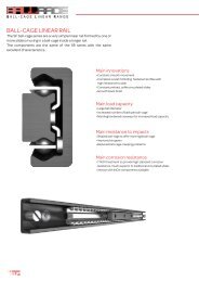
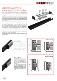
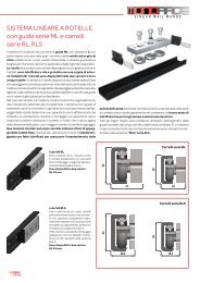
Linear Rail Mounting<br />
The availability of both countersunk (S-type) and counterbored (L-type)<br />
rail mounting holes allows optimization of alignment and orientation of<br />
the rails, depending on load direction and geometry.<br />
Generally the countersunk S-type rail is mounted with flathead screws<br />
and does not require special alignment, because the taper of the fastener<br />
and rail mounting hole, forces a rail into a specific position. Such<br />
rail mounting holes, allow for easy and fast rail installation, however the<br />
precision of the tapped hole placement in the mounting surface will affect<br />
the position of the rail.<br />
The counterbored holes in L-type rails allows for a small amount of lateral<br />
movement during installation.<br />
This type of mounting is preferred when the tapped holes in the mounting<br />
surface are not precisely placed. This type of mounting holes are<br />
necessary, when aligning the rail with an external reference surface, as<br />
the holes will allow the rail to move slightly, to sit against the reference<br />
surface.<br />
The rail must be secured to a structure sufficiently rigid to support the<br />
full load. The surface mounting holes should include a chamfer as shown<br />
in the table.<br />
Rail with Countersunk holes – Type-“S”<br />
Rail with Counterbored holes – Type –“L”<br />
Clearance<br />
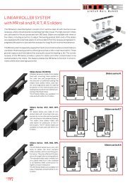
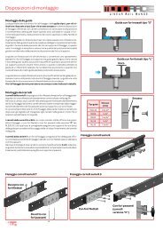
Slider <strong>Assembly</strong><br />
R sliders for MR and ML rails, have threaded holes parallel with the holes of<br />
the rail and aligned within the tolerance shown on page 36. In case of more<br />
sliders in same rail, the misalignment of the fixing holes of various sliders is<br />
compensated by making a bit larger holes on the fixing structure.<br />
It is recommended to only fully tighten the sliders mounting screws after<br />
installing all sliders in all the rails.<br />
This allows the sliders to align to the rail, avoiding creating additional<br />
stress on the sliders.R_S and RLS sliders have a slim slider body and allow<br />
for double slider fixing, with either threaded holes (standard) or a through<br />
hole, by adding a “C” designation to the part number (i.e. RLS28C-3).<br />
In case of through holes, it is advisable to drill some holes in the rail for access<br />
to the screws, for tightening after the sliders with screws are inserted<br />
into the rail. The RT sliders have mounting holes perpendicular to the rail<br />
mounting holes and offer the options of mounting from above or from below.<br />
In case where two sliders in respective version A and B, are installed in<br />
same rail, it might be necessary to shim the slider body thicknessupport,<br />
as eventual presence of minor misalignement (see tolerance on page 36)<br />
of slider body thickness.<br />
Rail<br />
type<br />
Chamfer<br />
(mm)<br />
MRG18 0.5x45°<br />
MR28 1x45°<br />
MR43 1.5x45°<br />
ML28 1x45°<br />
ML43 1.5x45°<br />
Slider fixing for series R.<br />
Chamfer<br />
Slider fixing for series R.T<br />
Slider fixing for series R.S<br />
Top-side fixing<br />
with threaded<br />
holes<br />
Bottom-side fixing<br />
with through passing holes<br />
Threaded holes<br />
Through passing<br />
holes<br />
(version “C”)<br />
30
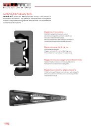
Examples of Mounting Arrangements<br />
a) A pair of rails mounted on facing walls with S-type mounting<br />
holes, for fast installation. Combined with self-aligning RA sliders<br />
(rotating) and RP or RF sliders (floating), such linear system<br />
is capable of self adjusting for some mm of parallelism errors<br />
between the two walls, see also page 37 for further info.<br />
a)<br />
b) A pair of rails mounted to the same horizontal surface with<br />
“L” brackets to rotate the rails so they are loaded radially. The “L”<br />
type rails with counterbored holes are used to ensure full support<br />
of the rail on the horizontal surface. RVT sliders are fixed<br />
to a plate from above. Use of “L” type rails provides maximum<br />
rigidity of parallel rails.<br />
c) Rails are mounted on perpendicullar surfaces. The upper rail<br />
is of type S with countersunk<br />
holes for quick mounting and<br />
combined with a RAT slider to<br />
support the weight, but also MR43S/RAT43-3<br />
for allowing some rotational<br />
movement. The lower rail is<br />
with counterbored holes to<br />
allow rail adjustment against<br />
the vertical surface and is<br />
combinded with an RFS slider<br />
to allow for unlimited vertical<br />
compensation. The system<br />
simplifies installation and allows<br />
alignment of the rails on<br />
both the vertical plane and<br />
horizontal plane.<br />
MR43S/RA43-3<br />
MR43L/RVT43-3<br />
b)<br />
MR43S/RF43-3<br />
MR43L/RVT43-3<br />
d) Rails are mounted flat on a<br />
horizontal surface and loaded<br />
axially.<br />
The two rails are “L” type with<br />
counterbored mounting holes<br />
to allow proper rail alignment.<br />
One of the two rails should be<br />
pushed against a lateral support<br />
for precise alignment of<br />
the movement‘s linearity. The<br />
sliders are fixed to a carriage<br />
plate and the second rail is fastened<br />
in place while moving<br />
the carriage assembly along<br />
the full travel to ensure parallelism<br />
of the rails. The RV-sliders<br />
offer maximum stiffness<br />
and load capacity in the axial<br />
direction<br />
MR43L/RFS43-3<br />
c)<br />
MR43L/RV43-3<br />
d)<br />
MR43L/RV43-3<br />
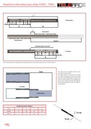
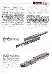
Slider orientation<br />
Slider with 3 rollers<br />
P<br />
Mark on Slider<br />
Sliders with 3 and 5 rollers provide maximum load capacity in the radial<br />
direction with the greater number of rollers on the same raceway<br />
of the rail. The side is marked with two circular impressions on the<br />
slider body.<br />
For example, sliders carrying a load as shown in the picture below<br />
should be oriented with the marks opposite the load direction.<br />
The marks indicate where the maximum reaction force is available.<br />
P<br />
Slider positioning with<br />
overhanging loads<br />
Slider with 5 rollers<br />
P<br />
Mark on Slider<br />
31
Preload setting of sliders<br />
L INEAR R AIL R ANGE<br />
Preload setting of sliders series R.<br />
When the sliders are ordered mounted in rail, the preload setting is<br />
done in factory, with our regolation instruments to assure a standard<br />
light preload P1, to assure no play and with optimal smooth running.<br />
As there might be minor differences of internal raceway distance,<br />
between same type of rails, already preload set sliders should not be<br />
used for other rails. I.e. each slider must be preload set to each rail.<br />
When sliders are purchased separately from the rail, the preload setting<br />
is done according to below procedure, depending on whether<br />
the slider is type R_ or RL or LA.Preload setting is permitted for all<br />
sliders by the eccentric roller; one for 3 roller-sliders or two eccentric<br />
rollers in case of 5 roller-sliders. The adjustable eccentric rollers<br />
should be in contact with the opposite raceway of the fixed-rollers,<br />
which are all concentric rollers :<br />
1)<br />
Procedure for preload setting of sliders serie R.<br />
To make the preload setting, one must act on the top screw, tightening<br />
the eccentric wheel (only accessible screw left on the top cover<br />
band) and the pivot of the eccentric roller, - on the other side. 2 Allen<br />
keys are needed.<br />
1 - Verify that the raceways are clean, take the wipers off, to obtain<br />
a more sensitive feeling for correct preload setting and smooth running.<br />
2 - Tighten the top-screw, but not too much, to allow a firm turning of<br />
the eccentric bottom-pivot, maintaining the roller tight to slider body.<br />
3 - Turn the eccentric pivot so that the roller is roughly aligned with<br />
the concentric rollers or slightly in the opposite direction of the concentric<br />
rollers.<br />
4 - Block the rail on a stable support, so hands are free. Insert the<br />
slider into the rail. Insert the Allen key into the pivot, through the rail<br />
fixing hole. Turn the Allen key slightly, so that the eccentric roller is<br />
coming in light contact with the raceways, opposite the fixed rollers.<br />
During the rotation, accompany the top-screw while rotating in the<br />
same direction with second Allen key, in order to avoid any loosening<br />
or change in preload setting.<br />
5 - Move the slider along the whole rail length to find the part/point,<br />
where the slider moves with less friction/most oscillations. By pressing/pulling<br />
the slider ends, any oscillation is detected. If any oscillation/play<br />
is noted, the eccentric roller must be re-adjusted. Perfect<br />
preload setting is achieved, when the slider moves very smoothly and<br />
with no play at this point, with “widest” raceway distance.<br />
The checking for oscilation is not possible for type: RA rotation slider<br />
or floating sliders RP, RF.<br />
6 - Holding firm against the Allen key, engaged in eccentric pivot with<br />
one hand, while with other Allen key rotate and tighten the top-screw<br />
fastening the roller. WARNING! Do not lock or unlock the eccentric<br />
roller by turning the pivot, always only act on the top-screw for blocking/loosening<br />
the roller.<br />
7 - It’s possible to verify the amount of preload by slowly inserting the<br />
slider at the end. The inserting force Fi is proportional to the preload.<br />
In general a good setting correspond to the following min/max. forces<br />
shown in Table 6b.<br />
8 - Then make final roller/screw blocking using a torque wrench, to<br />
assure right closing torque (Mt) according to the values in Table 7b,<br />
while maintaining the Allen key in pivot, to prevent any change of<br />
preload setting.<br />
2)<br />
Fixed<br />
concentric<br />
roller<br />
3)<br />
4)<br />
5)<br />
Pivoting<br />
eccentric<br />
roller<br />
6)<br />
Fixed<br />
concentric<br />
roller<br />
For 5-roller sliders, the above steps are repeated for each of the<br />
two eccentric rollers. When adjusting the second eccentric roller, it<br />
is necessary to visually assure, that the roller has got in contact with<br />
the raceway, to hereby rotate in opposite direction, compared to the<br />
fixed rollers, when moving the slider. This can be seen through the<br />
rails fixing holes. The homogeneity of preload setting, between the<br />
two eccentric rollers, can be verified by simply inserting the slider<br />
with the other end, i.e. after turning the slider 180 degrees.<br />
WARNING! After preload setting, assure that slider is inserted with<br />
fixed rollers positioned in direction of applied load.<br />
In case the rail is already installed, so no longer accessable from behind,<br />
the preload is set outside the rail, by tentatively positioning of<br />
the eccentric roller in more steps, to finally obtain a smooth movement<br />
with no slider oscillation in the installed rail.<br />
32<br />
7)<br />
Slider type<br />
Fi - Inserting force<br />
min<br />
max<br />
R.18 0,5 N 2 N<br />
R.28 1 N 5 N<br />
R.43 2 N 10 N<br />
Slider type<br />
Mt - Tightning torque<br />
R.18 3 Nm<br />
R.28 9 Nm<br />
R.43 22 Nm
Procedure for preload setting of sliders serie<br />
PAZ, PAX .<br />
The PAZ/PAX sliders, like the R-sliders, have the preload setting done<br />
by adjustments of the central roller with eccentric pivot.<br />
The preload setting is done with 2 Allen keys and is similar to R-sliders,<br />
described on page 32.<br />
The closing torque Mt and inserting force for these sliders are shown<br />
in below tables.<br />
Preload setting of slider series PA.<br />
Slider type<br />
PAZ/PAX 26<br />
PAZ/PAX 40<br />
Mt - Tightning torque<br />
7 Nm<br />
23 Nm<br />
Slider type<br />
Fi - Inserting force<br />
min<br />
max<br />
PAZ/PAX 26 1 N 5 N<br />
PAZ/PAX 40 1 N 5 N<br />
Preload setting of slider series RL.<br />
Procedure for preload setting of sliders series RL.<br />
The RL sliders have unlike the R series, a special central square pivot<br />
accessable with a flat key inserted between slider body and eccentric<br />
roller.<br />
With this flat key, provided by T<strong>RACE</strong>, the correct preload setting is<br />
done following the concepts of adjustments described in page 32.<br />
While having the slider already inserted in rail.<br />
With this pivot concept, slider preload setting is too possible, while<br />
having both rail and slider already been installed.<br />
Regulation key KML<br />
Wipers for replacement series KT.<br />
Slider type<br />
RL28<br />
RL43<br />
Mt - Tightning torque<br />
7 Nm<br />
23 Nm<br />
Slider type<br />
Fi - Inserting force<br />
min<br />
max<br />
RL28 1 N 5 N<br />
RL43 2 N 10 N<br />
The flat key for preload<br />
setting of RL-sliders<br />
is supplied free of<br />
charge, on request. NB<br />
two type of keys, ref.<br />
below table.<br />
Slider type<br />
RL28<br />
RL43<br />
Lubrication of raceways<br />
Code for flat key<br />
KML28<br />
KML43<br />
All sliders, except PAZ and PAX series, are supplied with strong wipers with incorporated pre-oiled<br />
sponge, to provide a good greasing for a long period of operation. See table a right side for wiper codes<br />
for all sliders. The duration of this self-lubrication dependents on the employmental conditions and<br />
the level of environmental pollution. Usually under normal conditions, the self-lubricant wipers can last<br />
about 700 km, however they can easily be replaced with a kit of new wipers with sponge.<br />
The rollers are all, lubricated for life with grease of lithium type soap. The R_sliders have 2RS seals, while<br />
RL-sliders have metal 2Z seals.<br />
Lubrication is very important to assure a long operation life. For applications with high frequency and<br />
continuous movement, it is advisable to regularly clean the raceways and relubricate the sliders for<br />
every 100,000 cycles, depending on the operation environment. Grease of class NLGI2 (ISO 2137) is<br />
then recommended.<br />
Wiper codes<br />
Slider type<br />
KT- 18 R.18<br />
KT-28<br />
R.28, R. T28<br />
KT-43<br />
R.43, R. T43<br />
KTL-28<br />
RL28<br />
KTL-43<br />
RL43<br />
KTS-28<br />
R. S28<br />
KTS-43<br />
R. S43<br />
KTLS-28<br />
RLS28<br />
KTLS-43<br />
RLS43<br />
33
Spliced rails, composed of shorter preselected rails<br />
L INEAR R AIL R ANGE<br />
MR and ML rails can be supplied in longer lengths than offered<br />
in catalog, by splicing multiple rail segments together. These<br />
spliced rails must be ordered from the factory, while specifying<br />
the total length and the lengths of individual segments : “Example:<br />
MR43-6000 (4000 + 2000)” The spliced rail will be delivered<br />
in preselected segments length and with additional counterbored<br />
mounting holes added to the joining locations, in addtion<br />
to ground ends.<br />
The customer must add additional mounting holes in his structure<br />
for these additional holes at the joining location. End-screws<br />
for joining is too supplied free, same type as the standard screws<br />
for rails with cylindrical fixing holes.<br />
Alignment tool for spliced rails DAGA.<br />
To assure a correct<br />
alignment of the rail<br />
ends, an appropriate<br />
alignment tool can be<br />
purchased as a separate<br />
item. See drawing/table<br />
for product<br />
describtion and<br />
codes, at right side.<br />
Joining area for spliced rails<br />
PITCH 80<br />
A<br />
Additional<br />
holes at joint<br />
Rail type Joining screws Alignment tool A D d E<br />
MRG18 M4-TORX SP DAGA-MR18 16 9 5 1,9<br />
MR28 M5-TORX SP DAGA-MR28 16 11 6 2<br />
MR43 M8-TORX SP DAGA-MR43 22 18 10 3,2<br />
ML28 M5-TORX SP DAGA-ML28 16 11 6 2<br />
ML43 M8-TORX SP DAGA-ML43 22 18 10 3,2<br />
FXR M6-DIN 7984 DAGA-FXR 20 10,5 6,5 4,4<br />
d<br />
E<br />
D<br />
1)<br />
Installation instructions for rails composed of more lengths<br />
1) Begin by supporting the two rail segments at the splice location. Develop a support guide in the area of joining<br />
lengths. Insert the alignment tool DAGA from one end of the rail. Install the mounting screws including the<br />
two at the splice location, but do not fully tighten them, to allow for small rail movements.<br />
2) Place the alignment tool over the splice. Tighten the alignment tool screws to align the rail segments.<br />
Support<br />
3) Verify that rail mounting surfaces (back side and lateral side of the rail) are aligned. If not, it may be neccessary<br />
by use of shims, to maintain aligment after the mounting bolts are tightened and the alignment tool is<br />
removed.<br />
2)<br />
4) Tighten the bolts at the splice location by passing the Allen key through the holes in the alignment tool.<br />
Tighten the other mounting bolts in the rails.<br />
5) Loosen the alignment tool and remove it from one end.<br />
DAGA<br />
3) 4) 5)<br />
Shims<br />
34
Thrust force<br />
The force required to move a slider is contingent on several factors, which are summarized to each other<br />
in releation to the application. I.e. the actual load applied, the direction of the load, the preload setting of<br />
the slider, friction of wipers/lateral seals and bearing seals. In principle the slider, when preload in rail without<br />
a load applied, may require a thrust force of Fw, which is mainly due to the preload setting, than friction<br />
caused by wipers. Especially the friction generated by wipers/lateral seals/preoiled sponges tends to<br />
decrease after an initial period, as adapting their shapes the raceways. If removing the wipers, the thrust<br />
force Fo is then only based on the slider preload setting. The thrust<br />
force from slider preload setting may varie along the rail, due to minor<br />
parallellism tolerance of the rails internal raceways.<br />
The thrust force Ft of the slider with a radial load P applied, is approximately<br />
proportional to the load as a coefficient function of friction<br />
of the wheels, increased by the thrust force Fw from wipers and<br />
preload setting.<br />
Ft =(P x μ)+Fw<br />
In case that slider is without wipers the value Ft results by:<br />
Ft =(P x μ)+Fo<br />
The below table shows the indicative values of Fw and Fo of a minimum<br />
value and a maximum value, depending on the preload setting<br />
of the slider. The result of Ft simplified formula is reasonably valid for<br />
applied loads greater than 10% of the maximum permissible load.<br />
For lower loads the coefficient of friction is increased up to twice the<br />
original value.<br />
P<br />
Ft<br />
Slider type<br />
Fo<br />
Static friction of slider without load<br />
and without wipers<br />
Fw<br />
Static friction of slider without load<br />
and with wipers<br />
μ μ<br />
Friction coefficient of rollers<br />
R.18 from 0,2 N to 0,5 N from 1 N to 1,5 N 0,005<br />
R.28 from 0,5 N to 1,5 N from 2,5 N to 3,5 N 0,005<br />
R.43 from 1 N to 3,5 N from 6 N to 10 N 0,005<br />
RL/RLS/R.S28 from 0,5 N to 1,5 N from 2,5 N to 3,5 N 0,005<br />
RL/RLS/R.S43 from 1 N to 3,5 N from 6 N to 10 N 0,005<br />
PAZ-PAX from 0,1 N to 0,6 N 0,008<br />
Noise and speed<br />
T <strong>RACE</strong>’s roller sliders offer high operating speed up to 10m/s, with almost no noise, when compared to recirculating ball-sliders. The table on right side, shows the max.<br />
speed for different slider types. The R sliders with wipers and lateral seals, may emit a minor friction noise at no applied load, which however tends to decrease during<br />
use, as the parts adapt to the shapes of the raceways<br />
Slider type<br />
Max. speed<br />
R.18 5 m/s<br />
R.28 7 m/s<br />
R.43 10 m/s<br />
RL/RLS/R.S28<br />
7 m/s<br />
RL/RLS/R.S43<br />
10 m/s<br />
PAZ-PAX<br />
5 m/s<br />
35
Construction tolerances<br />
The construction tolerances for the assembled dimensions of rails with<br />
their relative sliders are shown in below table. This too in relation to the<br />
rail mounting hole tolerances and mounting holes of the sliders.<br />
In particular, it is necessary to take into account the possibility that<br />
the axis of slider symmetry, may be slightly misaligned with the axis of<br />
L INEAR R AIL R ANGE<br />
symmetry of the rails. This mismatch may be larger in case of use of two<br />
sliders in same rail, of which one is postioned with load direction in opporsite<br />
load directions.<br />
This misalignments can be compensated while making the fixing holes<br />
sligthly larger on both fixed and mobile parts.<br />
F<br />
E<br />
D<br />
C<br />
G<br />
A<br />
B<br />
Rail type<br />
Slider type<br />
Tolerance<br />
A B C D E F G<br />
MRG18 R.G18 +0,15/-0,1 +0,2/-0,25 0/-0,1 +0,2/-0,2 +0,3/-0,35 0,2 0,8<br />
R.28 +0,15/-0,1 +0,2/-0,25 0/-0,1 +0,2/-0,2 +0,3/-0,35 0,2 0,8<br />
MR28<br />
R.S28 +0,1/-0,15 +0,25/-0,25 0/-0,1 +0,2/-0,2 +0,35/-0,35 0,3 1,0<br />
R.T28 +0,1/-0,15 +0,25/-0,25 0/-0,1 +0,2/-0,2 0,2 0,8<br />
R.43 +0,15/-0,1 +0,2/-0,25 0/-0,1 +0,2/-0,2 +0,3/-0,35 0,2 0,8<br />
MR43<br />
R.S43 +0,1/-0,15 +0,25/-0,25 0/-0,1 +0,2/-0,2 +0,3/-0,35 0,3 1,0<br />
R.T43 +0,1/-0,15 +0,25/-0,25 0/-0,1 +0,2/-0,2 0,2 0,8<br />
ML28<br />
RL28 +0,1/-0,15 +0,25/-0,25 0/-0,1 +0,2/-0,2 +0,35/-0,35 0,2 1,0<br />
RLS28 +0,1/-0,15 +0,25/-0,25 0/-0,1 +0,2/-0,2 +0,35/-0,35 0,2 1,0<br />
ML43<br />
RL43 +0,1/-0,15 +0,25/-0,25 0/-0,1 +0,2/-0,2 +0,35/-0,35 0,2 1,0<br />
RLS43 +0,1/-0,15 +0,25/-0,25 0/-0,1 +0,2/-0,2 +0,35/-0,35 0,2 1,0<br />
LAZ26, LAX26 PAZ26, PAX26 +0,25/-0,25 +0,4/-0,4 0/-0,1 +0,3/-0,3 +0,5/-0,5 0,3 1,0<br />
LAZ40, LAX40 PAZ40, PAX40 +0,25/-0,25 +0,4/-0,4 0/-0,1 +0,3/-0,3 +0,5/-0,5 0,3 1,0<br />
Linear Precision<br />
The linear precision as the deviation of the sliders actual trajectory in relation to a theoretical straight line, is determined by the straightness of the surface in which the<br />
rail is fixed and the intrinsic precision of the rail. In reference to the linear precision of the sole rail, it is determined by the parallelism of the slider movement with respect<br />
to the two longitudinal planes of the rail, plan A and B.<br />
The values of A and B are shown in the below chart, as a function of<br />
the rail length = actual slider movement.<br />
The linear accuracy indicated in relation to plane A, is only achievable<br />
if the rail is fixed onto a perfectly straight/flat surfaces, using<br />
A<br />
all mounting holes. The linear accuracy indicated in relation to the<br />
side B is achievable only for rails with counterbored mounting holes,<br />
of series “L” , after having aligned the rail against a perfectly<br />
A<br />
straight reference side. In case rails with c’sunk mounting holes is<br />
used, the linear precision is related to the straightness of the structures<br />
mounting holes.<br />
The guide does not set free may not be perfectly straight (slightly<br />
arched on plan A) with no problem once clamped to a rigid structure.<br />
B<br />
B<br />
36
<strong>Assembly</strong> tolerances for two parallel rails<br />
When two rails are used in parallel, it is necessary that the structure surfaces<br />
on which the rails are fixed, are parallel on different levels, with tolerance<br />
values within the figures given in below chart.<br />
Errors of parallelism greater than the values listed may cause additional<br />
load on rollers and rails, which hereby reduce the nominal load capacity<br />
and expected life-time (see coefficient of use page 38).<br />
In case of particularly high error values, it may also compromise the functionality<br />
movement.<br />
The MR rails combined with sliders of type RA, RP or RF can compensate<br />
larger mounting errors, due to the rollers contact geometry (see page 9).<br />
Hereby such Selfaligning system, can within certain limits, avoid additional<br />
load on rollers, which otherwise could compromise correct function<br />
of the linear system.<br />
The rails of series ML and LA do not provide such geometry Selfaligning<br />
compensation, but they are structurally more flexible (bearings with single<br />
row of balls, rails with less rigid raceways as thinner) and hereby able<br />
to accept a reasonable error of parallelism, corresponding to an additional<br />
internal load, when the errors are within the values listed in below<br />
chart.<br />
Floor A1<br />
Floor A2<br />
Floor B1<br />
Floor B2<br />
Slider combination<br />
Acceptable parallelism error (mm)<br />
Pair of parallel rails Sliders in rail A Sliders in rail B Between level A Between level A Between level B*<br />
MRG18<br />
RVG18 RVG18 0,03 0,02 0,5<br />
RAG18 RPG18 1 0,4 8<br />
RV28, RVS28 RV28, RVS28 0,04 0,02 0,6<br />
MR28<br />
RA28, RAS28 RP28, RPS28 1,2 0,5 9<br />
RA28, RAS28 RF28, RFS28 3 0,5 8<br />
RV43, RVS43 RV43, RVS43 0,05 0,04 0,7<br />
MR43<br />
RA43, RAS43 RP43, RPS43 2 0,6 10<br />
RA43, RAS43 RF43, RFS43 4 0,6 10<br />
ML28 RL28, RLS28 RL28, RLS28 0,07 0,04 0,8<br />
ML43 RL43, RLS43 RL43, RLS43 0,09 0,06 0,8<br />
LAZ, LAX, LAN PAZ, PAX PAZ, PAX 0,2 0,2 1<br />
* Value related at a distance between the two rails of about 500 mm..<br />
37
Sizing verification<br />
L INEAR R AIL R ANGE<br />
After identifying the most appropriate positioning of rails and sliders, or eventually the single<br />
rollers, it is necessary to verify the proper sizing of the linear components.<br />
This both from a static point of view and in accordance to the expected life-time.<br />
For the static verification it is necessary to determine the load on each slider or roller, and<br />
then identify the most stressed one. Then verify the values of the safety coefficients, while<br />
comparing with the max. nominal load capacities. When the applied load is a combination of<br />
loads; radial and/or axial loads and moments, it is necessary to determine the value of each<br />
factor and verify that:<br />
Load direction<br />
Mz<br />
Co rad<br />
Pax<br />
Co ax<br />
Prad Mex Mey Mez<br />
+ +<br />
+ +<br />
= 1<br />
The radial load capacity for all sliders is the side with 2 engraved<br />
marks, ref. page 31.<br />
It is recommended to apply the following values to safety coefficient Z:<br />
Z<br />
1 - 1,5<br />
Application conditions<br />
Accurate determination of static and dynamic loads. Precise<br />
assembly, tight structure.<br />
1,5 - 2 Avarage conditions<br />
2 - 3,5<br />
Insufficient determination of applied loads. Vibrations, loose structure.<br />
Imprecise assembly. Unfavourable einvironmental conditions.<br />
Theoretical lifetime calculation<br />
The theoretical life of the rollers and raceways of rail should be determined by the<br />
conventional formula as indicated below in km of running, however, should keep in<br />
mind that the value thus calculated must be taken with caution just for orientation,<br />
in fact, the real service life achieved can be very different from that calculated value,<br />
because the phenomena of wear and fatigue are caused by factors not easy to<br />
predetermine, for example:<br />
Coefficient fc<br />
• Inaccuracy in the estimation of the real loading condition<br />
• Overloading for inaccuracies assembly<br />
• Vibration, shock and dynamic pulse stress<br />
• Raceways status of lubrication<br />
• Thermal excursions<br />
• Environmental pollution and dust<br />
• Damage mounting<br />
• Stroke length and frequency of movement<br />
3<br />
L (Km) = 100 •<br />
C<br />
fc<br />
•<br />
P<br />
n<br />
• fa<br />
Where:<br />
- C = Dynamic load coefficient of slider<br />
- P = The equivalent load applied on the most stressed slider<br />
Verified for each single slider<br />
- P =<br />
( )<br />
(<br />
P rad + Pax Mex Mey Mez<br />
Co ax<br />
+ Mx<br />
+ My<br />
+ Mz<br />
• Co rad<br />
- fc = Coefficient depending on the actual stroke length. This factor takes into<br />
account applications with short stroke. With value 1 the stroke is superior to 2m,<br />
with shorter stroke the value is less, ref “Graph Coefficient Fc”<br />
(<br />
fa<br />
0,7 - 1<br />
0,2 - 0,5<br />
0,05 - 0,1<br />
Application conditions<br />
Good lubrication and wipers mounted –<br />
No impurities on raceways –<br />
Correct installation<br />
Normal dusty factory ambient, some vibrations,<br />
temperature changes, no wipers<br />
Poor Lubrication, dusty ambient, vibrations,<br />
high temperature changes, no wipers<br />
- n = Number of sliders in same rail passing same raceway point<br />
- fa = Coefficient taking into account operational ambient and level of correct<br />
lubrication of raceways<br />
The correction factors fc and fa applied to the theoretical calculation<br />
formula have the sole purpose of guiding the designer qualitatively on<br />
the influence in the lifetime estimation of the real application conditions<br />
without any pretense of precision. For more details please contact the<br />
Technical Service T <strong>RACE</strong>.<br />
38
Materials and treatments<br />
The MR and ML rails are both made from high precision cold<br />
drawn profiles, produced from specific carbon steel to provide<br />
high dept hardness, by nitriding hardening treatment. This innovative<br />
process is called T-NOX, and is developed by T <strong>RACE</strong> to<br />
assure high hardness, low wear and a high resistance to corrosion.<br />
This chemical heat treatment is conducted in three phases:<br />
1) High depth nitriding<br />
2) Black oxidation<br />
3) Impregnation with corrosion inhibitors and mineral oil.<br />
The T NOX treatment is done on the complete rail surfaces, to<br />
also provide high corrosion protection on the raceways.<br />
Rails Material Treatments<br />
MR Series Steel for nitriding nitriding<br />
ML Series Steel for nitriding nitriding<br />
LAZ Series Steel Zinc plating<br />
LAX Series Stainless steel inox AISI 303 no<br />
The sliders use different materials according to below table<br />
Material<br />
Slider<br />
R. Series R.T, R.S Series RL, RLS Series PAZ Series R.SX Series PAX Series<br />
Slider body Zinc plated steel Zinc plated steel Zinc plated steel Zinc plated steel Stainless steel inox AISI 304<br />
Lateral seals Polycarbonate no no no no no<br />
Wipers<br />
Polycarbonate<br />
elastomer<br />
Polycarbonate<br />
elastomer<br />
Polycarbonate<br />
elastomer<br />
no<br />
Polycarbonate<br />
elastomer<br />
no<br />
Pre-oiled sponge Sintetic fibre with bearing oil no<br />
Sintetic fibre<br />
with bearing oil<br />
no<br />
Screws Bright zinc plated steel Stainless steel inox<br />
Pins and spring washer Spring steel no Stainless steel inox no<br />
Washer Hardened steel Stainless steel inox AISI 440C<br />
Bearing seals Neopren Zinc plated steel Neopren<br />
Bearing cage Polyamide Zinc plated steel Polyamide<br />
Working temperature<br />
The operation temperature for sliders are -30° / +130° Celsius, for which max, temperature is limited by the 2RS seals. For the sliders RL. and PAZ, with 2Z seals<br />
the max operation temperature is 170° . On request special greased rollers can be supplied for higher/lower temperature.<br />
39