army tm 3-6665-321-12&p air force to 11h2-23-1 marine corps
army tm 3-6665-321-12&p air force to 11h2-23-1 marine corps
army tm 3-6665-321-12&p air force to 11h2-23-1 marine corps

Create successful ePaper yourself
Turn your PDF publications into a flip-book with our unique Google optimized e-Paper software.
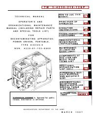
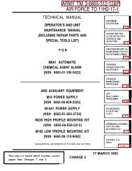
TECHNICAL MANUAL<br />
OPERATOR'S AND UNIT<br />
MAINTENANCE MANUAL<br />
(INCLUDING REPAIR PARTS AND<br />
SPECIAL TOOLS LIST)<br />
FOR<br />
ARMY TM 3-<strong>6665</strong>-<strong>321</strong>-12&P<br />
AIR FORCE TO 11H2-<strong>23</strong>-1<br />
MARINE CORPS 10434A-12&P<br />
NAVY (NAVSEA) EE168-DB-OMP-010<br />
ALARM, CHEMICAL AGENT, AUTOMATIC: M22<br />
(NSN: <strong>6665</strong>-01-438-6963) (EIC: Y14)<br />
AND<br />
AUXILIARY EQUIPMENT<br />
POWER SUPPLY, CHEMICAL AGENT AUTOMATIC ALARM: M28<br />
(NSN: 6130-01-438-6960) (EIC: Y40)<br />
MOUNTING KIT, CHEMICAL AGENT AUTOMATIC ALARM: M281<br />
(NSN: <strong>6665</strong>-01-438-6959) (EIC: Y38)<br />
ALARM UNIT, CHEMICAL AGENT AUTOMATIC ALARM: ABCA-M42<br />
(NSN: <strong>6665</strong>-00-859-2215) (EIC: 399)<br />
DISCLOSURE NOTICE - This information is furnished upon the condition that it will not be released <strong>to</strong> another nation<br />
without the specific authority of the Depar<strong>tm</strong>ent of the Army of the United States, that it will be used for military purposes<br />
only, that individual or corporate rights originating in the information, whether patented or not, will be respected, that the<br />
recipient will report promptly <strong>to</strong> the United States, any known or suspected compromise, and that the information will be<br />
provided substantially the same degree of security afforded it by the Depar<strong>tm</strong>ent of Defense of the United States. Also,<br />
regardless of any other markings on the document, it will not be downgraded or declassified without written approval of<br />
the originating United States agency.<br />
DISTRIBUTION STATEMENT C - Distribution authorized <strong>to</strong> U.S. Government agencies and their contrac<strong>to</strong>rs. This<br />
publication is required for administrative and operational purposes, as determined 26 March 1993. Other requests for<br />
this document shall be referred <strong>to</strong>: Technical Direc<strong>to</strong>r, Edgewood Research, Development and Engineering Center,<br />
ATTN: SCBRD-ENL-V, Aberdeen Proving Ground, Maryland 21010-54<strong>23</strong>. Marine Corps: Requests for this document<br />
must be referred <strong>to</strong>: Commandant of the Marine Corps (ARD), Washing<strong>to</strong>n, D.C. 20380-0001.<br />
WARNING - This document contains export-controlled technical data whose export is restricted by the Arms Export<br />
Control Act (Title 22, U.S.C., Sec 2751 et seq) or Executive Order 12470. Violation of these export laws are subject <strong>to</strong><br />
severe criminal penalties.<br />
DESTRUCTION NOTICE - For unclassified, limited documents, destroy by any method that will prevent disclosure of<br />
contents or reconstruction of the document.<br />
HEADQUARTERS, DEPARTMENTS OF THE ARMY, AIR FORCE,<br />
MARINE CORPS, AND NAVY<br />
1 MARCH 1998 PCN18210434000
ARMY TM 3-<strong>6665</strong>-<strong>321</strong>-12&P<br />
WARNING SUMMARY<br />
The following are general safety precautions and instructions that must be unders<strong>to</strong>od and applied during many phases<br />
of operation and maintenance <strong>to</strong> ensure personnel health and safety, and the protection of DoD property. Portions of this<br />
may be repeated elsewhere in this publication for emphasis.<br />
WARNING AND CAUTION STATEMENTS<br />
WARNING and CAUTION statements have been placed throughout this text prior <strong>to</strong> operating or maintenance<br />
procedures, practices or conditions considered essential <strong>to</strong> the protection of personnel (WARNING) or equipment and<br />
property (CAUTION). A WARNING or CAUTION will apply each time the related step is repeated. Prior <strong>to</strong> starting any<br />
task, the WARNINGS or CAUTIONS included in the text for that task must be reviewed and unders<strong>to</strong>od.<br />
This item contains radioactive material. Control of this radioactive material is mandated by federal law. Immediately<br />
report any suspected lost or damaged items <strong>to</strong> your Radiation Protection Officer. If your Radiation Protection Officer<br />
cannot be reached, contact the TACOM-ACALA Safety Office during regular duty hours at commercial (309) 782-6499 or<br />
DSN 793-6499 or call the Rock Island Police Office at DSN 793-6135 after duty hours.<br />
The sensor assembly inside the M88 Detec<strong>to</strong>r contains radioactive material in the form of two Nickel-63 sources. Do not<br />
attempt <strong>to</strong> open the M88 Detec<strong>to</strong>r or gain access <strong>to</strong> the radioactive source.<br />
Follow safety procedures for s<strong>to</strong>rage, shipment, and disposal in accordance with this manual, local regulation AR 710-3,<br />
AR 385-11 and AFI 40-201.<br />
Personal illness or DEATH may result if safety precautions are not observed. Toxic substances may be present in the<br />
system components if the M22 Alarm and auxiliary equipment is used during an actual chemical attack. MOPP IV gear<br />
should be worn while working with M22 Alarm and auxiliary equipment components that may be contaminated.<br />
Use a M256-series Detec<strong>to</strong>r Kit, M8/M9 Detec<strong>to</strong>r Paper, or a Chemical Agent Moni<strong>to</strong>r (CAM) <strong>to</strong> identify chemical agents<br />
that may not have been <strong>to</strong>tally removed during decontamination.<br />
High voltage is used in the operation of this equipment. Death on contact may result if personnel fail <strong>to</strong> observe safety<br />
precautions when performing maintenance procedures on the M28 Power Supply.<br />
Change 1 a
ARMY TM 3-<strong>6665</strong>-<strong>321</strong>-12&P<br />
WARNING SUMMARY (Continued)<br />
Do not connect or disconnect the M88 Detec<strong>to</strong>r and associated equipment in an explosive a<strong>tm</strong>osphere. An arc of<br />
electricity between connec<strong>to</strong>rs could cause an explosion.<br />
Ensure power is switched off and the AC power input cable is unplugged from the power source before any connection or<br />
disconnection is done.<br />
Surfaces of the M28 Power Supply can reach temperatures of 140°F (60°C) during operation. Do not <strong>to</strong>uch during<br />
operation. Switch Off and allow <strong>to</strong> cool prior <strong>to</strong> handling.<br />
The M88 Detec<strong>to</strong>r inlet can reach temperatures of 140°F (60°C) during operation. Switch Off the M88 Detec<strong>to</strong>r and allow<br />
the inlet <strong>to</strong> cool prior <strong>to</strong> any handling for maintenance.<br />
Ace<strong>to</strong>ne is extremely flammable and <strong>to</strong>xic. To prevent injury or death, use ace<strong>to</strong>ne in a well ventilated area. Wear<br />
appropriate protective covering and avoid prolonged breathing of fumes or contact with skin.<br />
The M88 Detec<strong>to</strong>r uses a Lithium-Sulfur Dioxide battery. This battery is a FLAMMABLE, CORROSIVE and VAPOR<br />
hazard. It contains lithium, sulfur dioxide, and an electrolyte. The lithium reacts vigorously when immersed in water.<br />
Sulfur dioxide is an irritant gas. The electrolyte is flammable and highly corrosive.<br />
DO NOT immerse the battery in water or decontamination solution.<br />
DO NOT crush or burn the battery.<br />
DO NOT attempt <strong>to</strong> recharge the battery.<br />
DO NOT s<strong>to</strong>re at temperatures above 158°F (70°C).<br />
DISPOSE of batteries according <strong>to</strong> Air Force TO 00-25-213, Army TB 43-0130, Marine Corps TI 6135-15/3, local SOP<br />
and SB 11-6 FSC 6135 Primary Battery Supply and Management Data.<br />
If any of the above precautions are not observed the lithium may rapidly vent out, carrying with it the sulfur dioxide gas<br />
and the electrolyte, and may heat up. If this happens, stay away until the smell of sulfur is gone. If you have <strong>to</strong> move the<br />
battery, move it outside by using a shovel or long <strong>to</strong>ngs. Wear suitable protection when handling explosive and corrosive<br />
hazards which may cause damage <strong>to</strong> skin and eyes. If the skin or eyes come in contact with the electrolyte, wash<br />
thoroughly with generous amounts of water, and seek medical attention.<br />
FIRST AID<br />
For first aid information refer <strong>to</strong> FM 21-11, FMFM 11-11, and NAVMED P-5041.<br />
Change 1 b
TM 3-<strong>6665</strong>-<strong>321</strong>-12&P<br />
INSERT LATEST UPDATED PAGES/WORK PACKAGES, DESTROY SUPERSEDED DATA<br />
LIST OF EFFECTIVE PAGES/WORK PACKAGES<br />
NOTE: The portion of text affected by the updates is indicated by a vertical line in the outer margins of the page.<br />
Changes <strong>to</strong> the RPSTL are also indicated by vertical lines in the margin.<br />
Dates of issue for original and updated pages/work pages are:<br />
Original……March 1998<br />
Change 1.… 21 May 1999<br />
TOTAL NUMBER OF PAGES IN THIS PUBLICATION IS 269. CONSISTING OF THE<br />
FOLLOWING:<br />
Page *Change Page *Change Page * Change<br />
No. No. No. No. No. No.<br />
Cover……………………0 2-26…………………….1 4-2 – 4-4……………0<br />
a & b..............................1 2-27…………………….0 4-5 Blank...…………0<br />
A & B............................1 2-28…………………….1 4-6 – 4-8…………....0<br />
i.....................................1 2-29 – 2-31…..…………0 4-9 Blank...…………0<br />
ii – vi .............................0 2-32…………………......1 4-10 – 4-16.………...0<br />
vii Blank........................0 2-33 – 2-39….………….0 4-17………………...1<br />
1-0.................................0 2-40……………....……..1 4-18……...…………0<br />
1-1 – 1-4........................1 2-41……...……………...0 4-19 – 4-28…………1<br />
1-5.................................0 2-42 & 2-43……..……...1 4-29 – 4-32...……….0<br />
1-6 Blank.......................0 2-44 & 2-45..…..……….0 4-33 Blank.....………0<br />
1-7 – 1-9........................0 2-46……………………..1 4-34 – 4-40…………0<br />
1-10 ...............................1 2-47 – 2-61……………..0 4-41 Blank………….0<br />
1-11……………………..0 2-62…………………….1 4-42…………………1<br />
1-12 Blank……………...0 2-63…………………….1 4-43……..………….0<br />
2-1………………………0 2-64 Blank.......…….…..0 4-44……...…………1<br />
2-2.................................1 3-1…………....………...0 4-45……..………….0<br />
2-3 – 2-20 ......................0 3-2………….....………..1 4-46……...…………1<br />
2-21 Blank.....................0 3-3 – 3-12.……………..0 4-47………………...0<br />
2-22 – 2-25……………..0 4-1……..……………….1 4-48 – 4-64…………0<br />
* Zero in this column indicates an original page. A Change 1
TM 3-<strong>6665</strong>-<strong>321</strong>-12&P<br />
INSERT LATEST UPDATED PAGES/WORK PACKAGES, DESTROY SUPERSEDED DATA<br />
LIST OF EFFECTIVE PAGES/WORK PACKAGES (Continued)<br />
NOTE: The portion of text affected by the updates is indicated by a vertical line in the outer margins of the page.<br />
Changes <strong>to</strong> the RPSTL are also indicated by vertical lines in the margin.<br />
Dates of issue for original and updated pages/work pages are:<br />
Original……March 1998<br />
Change 1.… 21 May 1999<br />
TOTAL NUMBER OF PAGES IN THIS PUBLICATION IS 269. CONSISTING OF THE<br />
FOLLOWING:<br />
Page *Change Page *Change Page * Change<br />
No. No. No. No. No. No.<br />
4-65 Blank……………...0 C-11 – C-17……………1 Index-8 Blank………….0<br />
4-66 – 4-68……………..0 C-18 – C-21……………0<br />
4-69 Blank……………...0 C-22 – C-24……………1<br />
4-70 – 4-72……………..0 D-1 & D-2……………..0<br />
4-73 Blank……………...0 D-3 – D-5………………1<br />
4-74 – 4-90……………..0 D-6……………………..0<br />
4-91……………………..1<br />
E-1……………………..1<br />
4-92 Blank……………...0 E-2 Blank……………...0<br />
A-1 & A-2………………1 F-1……………………..0<br />
A-3……………………...0<br />
F-2……..………………1<br />
B-1 – B-8……………….0 G-1 – G-3……………...0<br />
B-9……………………...1<br />
G-4 Blank……………...0<br />
B-10…………………….0<br />
H-1 & H-2……………..0<br />
C-1 – C-8……………….0 H-3 Blank……………..0<br />
C-9. ...............................1<br />
NRC Form 3…………..0<br />
C-10…………………….0<br />
Index 1 – Index-7...…...0<br />
B Change 1 * Zero in this column indicates an original page.
TM 3-<strong>6665</strong>-<strong>321</strong>-12&P<br />
C1<br />
CHANGE HEADQUARTERS<br />
DEPARTMENTS OF THE ARMY, AIR FORCE,<br />
NO. 1<br />
MARINE CORPS, AND NAVY<br />
WASHINGTON, D.C. 21 May 1999<br />
OPERATOR’S AND UNIT MAINTENANCE MANUAL<br />
(INCLUDING REPAIR PARTS AND SPECIAL TOOLS LIST)<br />
FOR<br />
ALARM, CHEMICAL AGENT, AUTOMATIC: M22<br />
(NSN: <strong>6665</strong>-01-438-6963) (EIC: Y14)<br />
AND<br />
AUXILIARY EQUIPMENT<br />
POWER SUPPLY, CHEMICAL AGENT AUTOMATIC ALARM: M28<br />
(NSN: 6130-01-438-6960) (EIC: Y40)<br />
MOUNTING KIT, CHEMICAL AGENT AUTOMATIC ALARM: M281<br />
(NSN: <strong>6665</strong>-01-438-6959) (EIC: Y38)<br />
ALARM UNIT, CHEMICAL AGENT AUTOMATIC ALARM: ABCA-M42<br />
(NSN: <strong>6665</strong>-00-859-2215) (EIC: 399)<br />
TM 3-<strong>6665</strong>-<strong>321</strong>-12&P, March 1998, is changed as follows:<br />
1. Remove old pages and insert new pages as indicated below.<br />
2. New or changed material is indicated by a vertical bar in the margin of the page.<br />
Remove Pages<br />
Insert Pages<br />
a and b<br />
a and b<br />
None<br />
A and B<br />
i and ii<br />
i and ii<br />
1-1 thru 1-4 1-1 thru 1-4<br />
1-9 and 1-10 1-9 and 1-10<br />
2-1 and 2-2 2-1 and 2-2<br />
2-25 thru 2-28 2-25 thru 2-28<br />
2-31 and 2-32 2-31 and 2-32<br />
2-39 thru 2-46 2-39 thru 2-46<br />
2-61 and 2-62 2-61 and 2-62<br />
None<br />
2-63/(2-64 Blank)<br />
3-1 and 3-2 3-1 and 3-2<br />
4-1 and 4-2 4-1 and 4-2<br />
4-17 thru 4-28 4-17 thru 4-28<br />
4-41 Blank thru 4-46 4-41 Blank thru 4-46<br />
4-91/(4-92 Blank) 4-91/(4-92 Blank)<br />
A-1 and A-2 A-1 and A-2<br />
B-9 and B-10 B-9 and B-10<br />
C-9 thru C-18 C-9 thru C-18<br />
C-21 thru C-24 C-21 thru C-24<br />
D-3 thru D-6 D-3 thru D-6<br />
E-1/(E-2 Blank) E-1/(E-2 Blank)<br />
F-1 and F-2 F-1 and F-2<br />
3. File this change sheet in front of the publication for reference purposes.
9913401<br />
To be distributed in accordance with initial distribution (IDN) 280834,<br />
requirements for special distribution for TM 3-<strong>6665</strong>-<strong>321</strong>-12&P
ARMY TM 3-<strong>6665</strong>-<strong>321</strong>-12&P<br />
TECHNICAL MANUAL<br />
OPERATOR'S AND UNIT<br />
MAINTENANCE MANUAL<br />
(INCLUDING REPAIR PARTS AND<br />
SPECIAL TOOLS LIST)<br />
FOR<br />
ALARM, CHEMICAL AGENT, AUTOMATIC: M22<br />
(NSN: <strong>6665</strong>-01-438-6963) (EIC: Y14)<br />
AND AUXILIARY EQUIPMENT<br />
POWER SUPPLY, CHEMICAL AGENT AUTOMATIC ALARM: M28<br />
(NSN: 6130-01-438-6960) (EIC: Y40)<br />
MOUNTING KIT, CHEMICAL AGENT AUTOMATIC ALARM: M281<br />
(NSN: <strong>6665</strong>-01-438-6959) (EIC: Y38)<br />
ALARM UNIT, CHEMICAL AGENT AUTOMATIC ALARM: ABCA-M42<br />
(NSN: <strong>6665</strong>-00-859-2215) (EIC: 399)<br />
REPORTING ERRORS AND RECOMMENDING IMPROVEMENTS.<br />
You can help improve this manual. If you find any mistake or if you know of a way <strong>to</strong> improve the procedures, please<br />
let us know. Mail your letter, DA Form 2028 (Recommended Changes <strong>to</strong> Publications and Blank Forms), or DA form<br />
2028-2 located in the back of this manual directly <strong>to</strong>: Commander, USA SBCCOM, ATTN: AMSSB-RBD-B,<br />
Aberdeen Proving Ground, MD 21010-5424. A reply will be furnished <strong>to</strong> you.<br />
Air Force users submit Air Force Technical Order Form 22 (AFTO Form 22), Technical Order System Publication<br />
Improvement Report and Reply, and submit according <strong>to</strong> TO 00-5-1, Air Force Technical Order System.<br />
Marine Corps users submit NAVMC 10772 <strong>to</strong>: Commander, Marine Corps Logistics Bases, Code 850, 814 Radford<br />
Boulevard, Albany, GA 31704-1128.<br />
Navy users submit NAVSEA TMDER 9086/10 <strong>to</strong>: Commanding Officer, Naval Ship Weapons Systems Engineering<br />
Station, Naval Sea Data Support Activity, Code 5H00, Port Hueneme, CA 93043-5007.<br />
DISCLOSURE NOTICE - This information is furnished upon the condition that it will not be released <strong>to</strong> another nation<br />
without the specific authority of the Depar<strong>tm</strong>ent of the Army of the United States, that it will be used for military purposes<br />
only, that individual or corporate rights originating in the information, whether patented or not, will be respected, that the<br />
recipient will report promptly <strong>to</strong> the United States, any known or suspected compromise, and that the information will be<br />
provided substantially the same degree of security afforded it by the Depar<strong>tm</strong>ent of Defense of the United States. Also,<br />
regardless of any other markings on the document, it will not be downgraded or declassified without written approval of<br />
the originating United States agency.<br />
DISTRIBUTION STATEMENT C - Distribution authorized <strong>to</strong> U.S. Government agencies and their contrac<strong>to</strong>rs. This<br />
publication is required for administration and operational purposes, as determined 26 March 1993. Other requests for this<br />
document shall be referred <strong>to</strong>: Commander, USA SBCCOM, ATTN: AMSSB-RBD-B, 5183 Blackhawk Road, Aberdeen<br />
Proving Ground, Maryland 21010-5424. Marine Corps: Requests for this document must be referred <strong>to</strong>: Commandant of<br />
the Marine Corps (ARD), Washing<strong>to</strong>n, D.C. 20380-0001.<br />
WARNING - This document contains export-controlled technical data whose export is restricted by the Arms Export<br />
Control Act (Title 22, U.S.C., Sec 2751 et seq) or Executive Order 12470. Violation of these export laws are subject <strong>to</strong><br />
severe criminal penalties.<br />
DESTRUCTION NOTICE - For unclassified, limited documents, destroy by any method that will prevent disclosure of<br />
contents or reconstruction of the document.<br />
HEADQUARTERS, DEPARTMENTS OF THE ARMY, AIR FORCE, MARINE CORPS, AND NAVY<br />
MARCH 1998<br />
Change 1 i
ARMY TM 3-<strong>6665</strong>-<strong>321</strong>-12&P<br />
TABLE OF CONTENTS<br />
Warning Summary...................................................................................................................................................a<br />
Warning and Caution Statements ............................................................................................................................a<br />
How <strong>to</strong> Use This Manual......................................................................................................................................... vi<br />
Chapter 1 Introduction .........................................................................................................................................1-1<br />
Section I General Information ..............................................................................................................................1-1<br />
1.1 Scope ......................................................................................................................................................1-1<br />
1.1.1 Type of Manual ..........................................................................................................................1-1<br />
1.1.2 Equipment Model Number and Name .........................................................................................1-1<br />
1.1.3 Purpose of Equipment ................................................................................................................1-1<br />
1.2 Maintenance Forms, Records, and Reports..............................................................................................1-1<br />
1.3 Reporting Equipment Improvement Recommendations (EIR) ...................................................................1-1<br />
1.4 Corrosion Prevention and Control (CPC)..................................................................................................1-2<br />
1.5 Destruction of Material <strong>to</strong> Prevent Enemy Use..........................................................................................1-2<br />
1.6 Preparation for S<strong>to</strong>rage or Shipment ........................................................................................................1-2<br />
1.7 Warranty Information................................................................................................................................1-2<br />
1.7.1 Army Warranty Information..........................................................................................................1-2<br />
1.7.2 Air Force Warranty Information....................................................................................................1-2<br />
1.7.3 Navy Warranty Information ..........................................................................................................1-2<br />
1.7.4 Marine Corps Warranty Information .............................................................................................1-2<br />
1.8 Nomenclature Cross Reference List........................................................................................................1-3<br />
1.9 List of Abbreviations................................................................................................................................1-3<br />
1.10 Safety, Care and Handling ....................................................................................................................1-4<br />
1.10.1 Rules and Regulations...............................................................................................................1-4<br />
1.10.2 NRC Posting Requirements.......................................................................................................1-5<br />
1.10.3 Emergency Procedures .............................................................................................................1-5<br />
1.11 Calibration ...........................................................................................................................................1-5<br />
Section II Equipment Description and Data ..........................................................................................................1-7<br />
1.12 Equipment Characteristics, Capabilities, and Features .........................................................................1-7<br />
1.12.1 Characteristics...........................................................................................................................1-7<br />
1.12.2 Capabilities and Features ..........................................................................................................1-7<br />
1.13 Location and Description of Major Components and Auxiliary Equipment .............................................1-8<br />
1.14 Equipment Data ...................................................................................................................................1-9<br />
1.14.1 M22 Alarm Operating and Performance Ranges ......................................................................1-10<br />
Section III Theory of Operation ..........................................................................................................................1-11<br />
1.15 Introduction........................................................................................................................................1-11<br />
1.16 Detailed Theory of Operation..............................................................................................................1-11<br />
Chapter 2 Operating Instructions .........................................................................................................................2-1<br />
Section I Description and Use of Opera<strong>to</strong>r's Controls and Indica<strong>to</strong>rs ....................................................................2-1<br />
2.1 M88 Detec<strong>to</strong>r .........................................................................................................................................2-1<br />
2.1.1 M88 Detec<strong>to</strong>r Opera<strong>to</strong>r Controls and Indica<strong>to</strong>rs ............................................................................2-1<br />
2.1.2 M88 Detec<strong>to</strong>r Display ...................................................................................................................2-2<br />
2.2 Confidence Sample................................................................................................................................2-4<br />
2.3 Battery Box ............................................................................................................................................2-5<br />
2.4 M28 Power Supply.................................................................................................................................2-6<br />
2.5 M42 Remote Alarm ................................................................................................................................2-8<br />
2.6 M281 Mounting Kit .................................................................................................................................2-9<br />
Section II Opera<strong>to</strong>r Preventive Maintenance Checks and Services (PMCS) and Manda<strong>to</strong>ry Replacement Parts.2-10<br />
2.7 Introduction..........................................................................................................................................2-10<br />
2.7.1 General.......................................................................................................................................2-10<br />
2.7.2 Warnings and Cautions ...............................................................................................................2-10<br />
2.7.3 Explanation of Table Entries........................................................................................................2-10<br />
Page<br />
ii
ARMY TM 3-<strong>6665</strong>-<strong>321</strong>-12&P<br />
TABLE OF CONTENTS (Continued)<br />
Section III Operation Under Usual Conditions.....................................................................................................2-25<br />
2.8 Assembly and Preparation for Use .......................................................................................................2-25<br />
2.8.1 Overview of Assembly .................................................................................................................2-25<br />
2.8.2 Assembly for Battery Operation ...................................................................................................2-26<br />
2.8.3 Assembly for M28 Power Supply Operation .................................................................................2-28<br />
2.8.4 Connect M42 Remote Alarm <strong>to</strong> M88 Detec<strong>to</strong>r (Use of M42 Remote Alarm is optional) .................2-30<br />
2.8.5 Installation in<strong>to</strong> M281 Mounting Kit ..............................................................................................2-32<br />
2.9 Operating Procedures ..........................................................................................................................2-35<br />
2.9.2 Initial Checks...............................................................................................................................2-35<br />
2.9.3 Initial Power On and Self-Test .....................................................................................................2-36<br />
2.9.4 Confidence Sample Testing.........................................................................................................2-38<br />
2.9.5 Audible Alarm Disabled................................................................................................................2-41<br />
2.9.6 Detec<strong>to</strong>r Operations.....................................................................................................................2-42<br />
2.10 Shutdown Procedures ........................................................................................................................2-44<br />
2.11 Disassembly and Preparation for S<strong>to</strong>rage or Shipment .......................................................................2-46<br />
2.12 Decals and Labels..............................................................................................................................2-56<br />
2.12.1 M88 Detec<strong>to</strong>r.............................................................................................................................2-56<br />
2.12.2 Battery Box................................................................................................................................2-57<br />
2.12.3 M28 Power Supply.....................................................................................................................2-58<br />
2.12.4 M281 Mount Assembly ..............................................................................................................2-59<br />
2.12.5 M42 Remote Alarm....................................................................................................................2-60<br />
Section IV Operation Under Unusual Conditions ................................................................................................2-61<br />
2.13 Operating in Wet or Dusty Conditions .................................................................................................2-61<br />
2.14 Emergency Procedures ......................................................................................................................2-62<br />
2.14.1 Power Failure ............................................................................................................................2-62<br />
2.14.2 M42 Remote Alarm Failure ........................................................................................................2-62<br />
2.14.3 Broken Audible Alarm on M88 Detec<strong>to</strong>r .....................................................................................2-62<br />
2.15 Nuclear, Biological, and Chemical (NBC) Decontamination.................................................................2-62<br />
Chapter 3 Opera<strong>to</strong>r Maintenance Procedures ..................................................................................................... 3-1<br />
Section I Lubrication Instructions......................................................................................................................... 3-1<br />
3.1 General................................................................................................................................................. 3-1<br />
Section II Troubleshooting Procedures................................................................................................................ 3-1<br />
3.2 Introduction ........................................................................................................................................... 3-1<br />
3.3 User Observed Malfunctions.................................................................................................................. 3-1<br />
Section III Opera<strong>to</strong>r Maintenance Procedures ..................................................................................................... 3-7<br />
3.4 General................................................................................................................................................. 3-7<br />
3.4.1 M88 Detec<strong>to</strong>r Inlet ........................................................................................................................ 3-8<br />
3.4.2 M42 Remote Alarm Batteries .......................................................................................................3-10<br />
Chapter 4 Unit Maintenance Procedures............................................................................................................. 4-1<br />
Section I Rep<strong>air</strong> Parts, Special Tools, TMDE, and Support Equipment ................................................................ 4-1<br />
4.1 Common Tools and Equipment ............................................................................................................. 4-1<br />
4.2 Special Tools, TMDE and Support Equipment ....................................................................................... 4-1<br />
4.3 Rep<strong>air</strong> Parts .......................................................................................................................................... 4-1<br />
Section II Service Upon Receipt.......................................................................................................................... 4-1<br />
4.4 Introduction ........................................................................................................................................... 4-1<br />
Section III Troubleshooting Procedures..............................................................................................................4-14<br />
4.5 Introduction ..........................................................................................................................................4-14<br />
4.6 Symp<strong>to</strong>m Index ....................................................................................................................................4-14<br />
Section IV Unit Maintenance Procedures ...........................................................................................................4-27<br />
4.7 M22 Au<strong>to</strong>matic Alarm ...........................................................................................................................4-29<br />
4.7.1 Transit Case................................................................................................................................4-29<br />
4.8 M88 Detec<strong>to</strong>r .......................................................................................................................................4-30<br />
Page<br />
iii
ARMY TM 3-<strong>6665</strong>-<strong>321</strong>-12&P<br />
TABLE OF CONTENTS (Continued)<br />
4.8.1 Switch Knob ................................................................................................................................4-30<br />
4.8.2 Electrical Cap..............................................................................................................................4-32<br />
4.8.3 Handle ........................................................................................................................................4-34<br />
4.8.4 Connec<strong>to</strong>r Cap............................................................................................................................4-36<br />
4.9 Battery Box ..........................................................................................................................................4-38<br />
4.9.1 Rim Latch....................................................................................................................................4-38<br />
4.10 Transit Case ......................................................................................................................................4-40<br />
4.10.1 Strap .........................................................................................................................................4-40<br />
4.11 M28 Power Supply.............................................................................................................................4-42<br />
4.11.1 M28 Power Supply ....................................................................................................................4-42<br />
4.11.2 DC Power Cable........................................................................................................................4-44<br />
4.11.3 AC Power Cable (110V/220V) ...................................................................................................4-46<br />
4.12 Vehicle Mount ....................................................................................................................................4-48<br />
4.12.1 Vehicle Mount ...........................................................................................................................4-48<br />
4.12.2 Junction Box .............................................................................................................................4-50<br />
4.12.3 Top Clamp Bar ..........................................................................................................................4-52<br />
4.12.4 Front Clamp Bar........................................................................................................................4-54<br />
4.12.5 Pad ...........................................................................................................................................4-56<br />
4.12.6 Slide Latch ................................................................................................................................4-58<br />
4.12.7 Vibration Mount .........................................................................................................................4-60<br />
4.12.8 Binding Post..............................................................................................................................4-62<br />
4.12.9 Electrical Cap............................................................................................................................4-64<br />
4.12.10 Cable Gland ............................................................................................................................4-66<br />
4.13 M42 Mount.........................................................................................................................................4-68<br />
4.13.1 M42 Mount ................................................................................................................................4-68<br />
4.13.2 Insula<strong>to</strong>r, Liner and Pad.............................................................................................................4-70<br />
4.14 M42 Remote Alarm ............................................................................................................................4-72<br />
4.14.1 M42 Remote Alarm ...................................................................................................................4-72<br />
4.14.2 Captive Screw ...........................................................................................................................4-74<br />
4.14.3 Lamp.........................................................................................................................................4-76<br />
4.14.4 Lens..........................................................................................................................................4-77<br />
4.14.5 Switch Knob ..............................................................................................................................4-78<br />
4.14.6 Electrical Cap............................................................................................................................4-80<br />
4.15 (Air Force Only) Air Force Wipe Test Procedures ...............................................................................4-81<br />
4.15.1 Preparation of the AF Form 495.................................................................................................4-81<br />
4.15.2 Wipe Collection Procedures.......................................................................................................4-82<br />
4.16 (Marine Corps Only) Marine Corps Wipe Test Procedures..................................................................4-84<br />
4.16.1 Preparation of the Wipe Label ...................................................................................................4-84<br />
4.16.2 Wipe Collection Procedures.......................................................................................................4-85<br />
4.17 (Navy Only) Navy Wipe Test Procedures............................................................................................4-87<br />
4.17.1 Leak Test Instructions for the M22 ACADA Containing Radioactive Sources..............................4-87<br />
4.17.2 Leak Test Procedure .................................................................................................................4-88<br />
4.18 Installation of M281 Mounting Kit........................................................................................................4-89<br />
4.18.1 Introduction ...............................................................................................................................4-89<br />
4.18.2 Installation of Vehicle Mount......................................................................................................4-89<br />
4.18.3 Installation of M42 Mount...........................................................................................................4-89<br />
Section V Preparation for S<strong>to</strong>rage and Shipment ...............................................................................................4-90<br />
4.19 S<strong>to</strong>rage..............................................................................................................................................4-90<br />
4.20 Packing and Shipment .......................................................................................................................4-90<br />
4.21 Accountability.....................................................................................................................................4-91<br />
Page<br />
iv
ARMY TM 3-<strong>6665</strong>-<strong>321</strong>-12&P<br />
TABLE OF CONTENTS (Continued)<br />
Page<br />
Appendix A References ...................................................................................................................................... A-1<br />
Appendix B Maintenance Allocation Chart (MAC)................................................................................................ B-1<br />
Appendix C Opera<strong>to</strong>r and Unit Maintenance Rep<strong>air</strong> Parts and Special Tools List ................................................C-1<br />
C-1 00 Alarm, Chemical Agent, Au<strong>to</strong>matic: M22 .............................................................................................C-8<br />
C-2 01 Detec<strong>to</strong>r Unit, Chemical Agent, Au<strong>to</strong>matic: M88................................................................................C-10<br />
C-3 02 Battery Box.......................................................................................................................................C-12<br />
C-4 03 Transit Case Assembly.....................................................................................................................C-13<br />
C-5 00 Power Supply, Chemical Agent Au<strong>to</strong>matic Alarm: M28......................................................................C-14<br />
C-6 00 Mounting Kit, Chemical Agent Au<strong>to</strong>matic Alarm: M281......................................................................C-15<br />
C-7 01 Vehicle Mount Assembly...................................................................................................................C-16<br />
C-8 0101 Junction Box.................................................................................................................................C-17<br />
C-9 02 Base, Chassis...................................................................................................................................C-18<br />
C-10 00 Alarm Unit, Chemical Agent Au<strong>to</strong>matic Alarm: ABCA-M42 ..............................................................C-19<br />
C-11 01 Panel Assembly..............................................................................................................................C-20<br />
Appendix D Components of End Item and Basic Issue Items Lists.......................................................................D-1<br />
Appendix E Additional Authorization List ............................................................................................................. E-1<br />
Appendix F Expendable and Durable Items......................................................................................................... F-1<br />
Appendix G Illustrated List of Manufactured Items...............................................................................................G-1<br />
Appendix H Nuclear Regula<strong>to</strong>ry Commission Requirements................................................................................H-1<br />
Index ...........................................................................................................................................................INDEX-1<br />
v
ARMY TM 3-<strong>6665</strong>-<strong>321</strong>-12&P<br />
HOW TO USE THIS MANUAL<br />
This manual has been designed <strong>to</strong> enable opera<strong>to</strong>rs and unit maintenance personnel <strong>to</strong> effectively maintain the ALARM,<br />
CHEMICAL AGENT, AUTOMATIC, M22 and supporting auxiliary equipment POWER SUPPLY, CHEMICAL AGENT<br />
AUTOMATIC ALARM, M28 and MOUNTING KIT, CHEMICAL AGENT AUTOMATIC ALARM, M281 in the field.<br />
A summary contents listing is provided in the table of contents. A comprehensive cross-referenced index is located at<br />
the end of the manual. These listings will help you <strong>to</strong> locate more detailed information.<br />
CHAPTER 1 contains introduc<strong>to</strong>ry information. Sub<strong>to</strong>pics of importance <strong>to</strong> you include: the purpose of the ALARM,<br />
CHEMICAL AGENT, AUTOMATIC, M22 and supporting auxiliary equipment POWER SUPPLY, CHEMICAL AGENT<br />
AUTOMATIC ALARM, M28 and MOUNTING KIT, CHEMICAL AGENT AUTOMATIC ALARM, M281. This chapter<br />
describes the equipment limitations; characteristics, capabilities, and features; location and description of major<br />
components; technical principles of operation; safety, care, and handling; and forms, records and reports.<br />
CHAPTER 2 provides you with instructions on how <strong>to</strong> operate the ALARM, CHEMICAL AGENT, AUTOMATIC, M22 and<br />
supporting auxiliary equipment POWER SUPPLY, CHEMICAL AGENT AUTOMATIC ALARM, M28 and MOUNTING<br />
KIT, CHEMICAL AGENT AUTOMATIC ALARM, M281; confidence testing; setup, operating and shut down procedures;<br />
preparation for s<strong>to</strong>rage and transport, emergency and decontamination procedures.<br />
CHAPTER 3 provides you with opera<strong>to</strong>r level troubleshooting and maintenance information.<br />
CHAPTER 4 provides you with service upon receipt inspection procedures; unit level troubleshooting and maintenance<br />
information. Wipe test procedures in this TM are for use by Air Force, Marine Corps and Navy personnel only.<br />
APPENDIX A is a reference list of frequently used forms and publications.<br />
APPENDIX B contains the Maintenance Allocation Chart for the M22 Alarm, M28 Power Supply, M281 Mounting Kit and<br />
M42 Remote Alarm.<br />
APPENDIX C is a Rep<strong>air</strong> Parts and Special Tools List (RPSTL) that lists and authorizes spares and rep<strong>air</strong> parts, special<br />
<strong>to</strong>ols, special test, measurement and diagnostic equipment (TMDE), and other special support equipment required for<br />
performance of opera<strong>to</strong>r and unit maintenance.<br />
APPENDIX D lists the Components of End Items (COEI) and the Basic Issue Items (BII).<br />
APPENDIX E lists the Additional Authorized List (AAL) items.<br />
APPENDIX F lists the Expendable and Durable items required <strong>to</strong> operate or maintain the M22 Alarm.<br />
APPENDIX G is an illustrated list of manufactured items.<br />
APPENDIX H is an example of the U.S. Nuclear Regula<strong>to</strong>ry Commission form.<br />
The Index follows the appendixes. You will find it useful in locating page numbers about specific information or<br />
procedures.<br />
Army form, DA Form 2028-2, is provided in the back of this manual for your use in making recommended improvements<br />
<strong>to</strong> this manual. Marine Corps and Navy users should submit NAVMC 10772 when making recommended improvements<br />
<strong>to</strong> this manual.<br />
WARNING and CAUTION statements have been placed throughout this text prior <strong>to</strong> operating or maintenance<br />
procedures, practices or conditions considered essential <strong>to</strong> the protection of personnel (WARNING) or equipment and<br />
property (CAUTION). A WARNING or CAUTION will apply each time the related step is repeated. Prior <strong>to</strong> starting any<br />
task, the WARNINGS or CAUTIONS included in the text for that task must be reviewed and unders<strong>to</strong>od.<br />
vi
ARMY TM 3-<strong>6665</strong>-<strong>321</strong>-12&P<br />
M22 Alarm and Auxiliary Equipment<br />
1-0
ARMY TM 3-<strong>6665</strong>-<strong>321</strong>-12&P<br />
CHAPTER 1<br />
INTRODUCTION<br />
SECTION I. GENERAL INFORMATION<br />
1.1 SCOPE. The scope of this manual is described in the following subparagraphs.<br />
1.1.1 Type of Manual. This manual covers the opera<strong>to</strong>r's and unit maintenance (including rep<strong>air</strong> parts and<br />
special <strong>to</strong>ols list) for the ALARM, CHEMICAL AGENT, AUTOMATIC: M22 (NSN <strong>6665</strong>-01-438-6963) and<br />
auxiliary equipment including the Power Supply: Chemical Agent Au<strong>to</strong>matic Alarm, M28 (NSN 6120-01-438-<br />
6994); MOUNTING KIT: Chemical Agent Au<strong>to</strong>matic Alarm, M281 (NSN <strong>6665</strong>-01-438-6959) and the ALARM<br />
UNIT: Chemical Agent Au<strong>to</strong>matic, ABCA-M42 (NSN <strong>6665</strong>-00-859-2215).<br />
1.1.2 Equipment Model Number and Name. ALARM, CHEMICAL AGENT, AUTOMATIC: M22<br />
1.1.3 Purpose of Equipment. The ALARM, CHEMICAL AGENT, AUTOMATIC: M22 detects and senses<br />
chemical warfare nerve (G-Series) and blister (H-Series) agents in the <strong>air</strong> and provides a visual and audible<br />
warning via the built-in display and audible alarm or the ABCA-M42 Alarm Unit. The M22 bar-graph display<br />
indicates the concentration levels of the hazardous agent vapors detected by agent class.<br />
1.2 MAINTENANCE FORMS, RECORDS, AND REPORTS.<br />
1.2.1 Army personnel will use Depar<strong>tm</strong>ent of the Army forms and procedures used for equipment maintenance<br />
prescribed by DA Pam 738-750 (The Army Maintenance Management System (TAMMS)) (Maintenance<br />
Management Update).<br />
1.2.2 Air Force personnel will comply with Air Force Technical Order (TO) 11W-1-10 and Air Force (AF) Form<br />
105 for maintenance actions.<br />
1.2.3 Marine Corps personnel refer <strong>to</strong> the on-line Marine Corps Publication Distribution System (MCPDS) or<br />
Marine Corps S<strong>to</strong>ck list SL-1-2 Index of Technical Publications. Marine Corps personnel will use TM 4700-<br />
15/1, (Equipment Record Procedures).<br />
1.2.4 Navy personnel will comply with OPNAVINST 4790.4C for required maintenance actions and reporting.<br />
1.3 REPORTING EQUIPMENT IMPROVEMENT RECOMMENDATIONS (EIR).<br />
If your M22 or auxiliary equipment needs improvement, let us know. Send us an EIR. You, the user, are the<br />
only one who can tell us what you do not like about your equipment. Let us know why you do not like the<br />
design or performance. Document it on an SF 368 (Product Quality Deficiency Report). Mail your completed<br />
SF 368 <strong>to</strong>:<br />
Army:<br />
Commander<br />
U.S. Army Soldier and Biological Chemical Command (SBCCOM)<br />
Integrated Material Management Center (IMMC)<br />
ATTN: AMSSC-I-LO-E<br />
Kansas Street<br />
Natick, MA 01760-5052<br />
DSN 256-4484, Commercial (508) <strong>23</strong>3-4484, FAX ext 4471<br />
Office of the Project Manager for NBC Defense Systems<br />
ATTN: AMSCB-PM-NNJ/ACADA Team<br />
Aberdeen Proving Ground, MD 21010-5424<br />
DSN 584-5628, Commercial (410) 436-5628 or 5940, FAX ext 6526<br />
Air Force:<br />
HSC/YAC<br />
8107 13 th Street<br />
Brooks AFB, TX 78<strong>23</strong>5-5218<br />
DSN 240-<strong>23</strong>74<br />
Change 1 1-1
ARMY TM 3-<strong>6665</strong>-<strong>321</strong>-12&P<br />
1.3 REPORTING EQUIPMENT IMPROVEMENT RECOMMENDATIONS (EIR). (Continued)<br />
Marine Corps: Submit an SF 368 In Accordance With (IAW) MCO 4855.10 directly <strong>to</strong>:<br />
Commander<br />
Marine Corps Logistics Bases<br />
ATTN: Code G316-1, 814 Radford Boulevard<br />
Albany, GA 31704-1128<br />
Navy:<br />
Commander<br />
CODE 805D<br />
NAVSURFWARCENDIV<br />
300 Highway 361<br />
Crane, IN 47522-5001<br />
1.4 CORROSION PREVENTION AND CONTROL (CPC).<br />
1.4.1 Corrosion Prevention and Control (CPC) of Army material is a continuing concern. It is important that<br />
any corrosion problems with this item be reported so that the problem can be corrected and improvements<br />
made <strong>to</strong> prevent the problems in the future.<br />
1.4.2 While corrosion is typically associated with rusting metals, it can also include deterioration of other<br />
materials, such as rubber and plastic. Unusual cracking, softening, swelling, or breaking of these materials<br />
may be a corrosion problem.<br />
1.4.3 If a corrosion problem is identified, it shall be reported using a Standard Form (SF) 368, Product Quality<br />
Deficiency Report IAW Appendix A. Use of keywords such as "corrosion," "rust," "deterioration," or "cracking"<br />
will ensure that the information is identified as a CPC problem.<br />
1.5 DESTRUCTION OF MATERIAL TO PREVENT ENEMY USE. Destroy the M22 and auxiliary equipment<br />
(except vehicle mounts) IAW TM 43-0002-31, Procedures for Destruction of Alarm Systems. Destruction of<br />
vehicle mounts is accomplished when the vehicle <strong>to</strong> which they are attached is destroyed.<br />
1.6 PREPARATION FOR STORAGE OR SHIPMENT. Preparation for s<strong>to</strong>rage or shipment shall be<br />
accomplished IAW Chapter 4, Section V of this manual.<br />
1.7 WARRANTY INFORMATION. The ALARM, CHEMICAL AGENT, AUTOMATIC: M22 (NSN <strong>6665</strong>-01-<br />
438-6963) and auxiliary equipment including the Power Supply: Chemical Agent Au<strong>to</strong>matic Alarm, M28 (NSN<br />
6120-01-438-6994); and the MOUNTING KIT: Chemical Agent Au<strong>to</strong>matic Alarm, M281 (NSN <strong>6665</strong>-01-438-<br />
6959) are warranted for 3 years. The Sieve Pack Assembly, P/N 0614-<strong>23</strong>31, which is a spare part of the M88<br />
Detec<strong>to</strong>r (M88 is a component of M22), has a limited warranty of time/usage base.<br />
1.7.1 Army Warranty Information: The user initiates the warranty process by documenting failures on a<br />
SF-368, Product Quality Deficiency Report (PQDR), and submits in accordance with paragraph 1.3 The user<br />
will also send a copy of the PQDR <strong>to</strong> the ACADA Team via FAX at DSN 584-6526 or Commercial (410) 436-<br />
5628 or 5940. The user will then be contacted and provided disposition instructions. If failure is associated<br />
with the M88 Detec<strong>to</strong>r, the reading on the hour meter or an estimate if unable <strong>to</strong> read the hour meter must be<br />
recorded on the PQDR in block 13 (Single Item) or under block 22 (Multiple Items). This information is<br />
crucial in determining if the item is covered under warranty.<br />
1.7.2 Air Force Warranty Information. Contact the item manager as described in paragraph 1.3. Submit a<br />
copy of the PQDR via FAX <strong>to</strong> the ACADA team as described above in paragraph 1.7.1.<br />
1.7.3 Navy Warranty Information. Contact the In-Service Engineering Agent (ISEA) as described in<br />
paragraph 1.3, telephone DSN 482-5740 or 812-854-5740, fax 812-854-5828. Submit a copy of the PQDR via<br />
FAX <strong>to</strong> the ACADA team as described above in paragraph 1.7.1.<br />
1.7.4 Marine Corps Warranty Information. Contact Commander, ATTN: Code 835-3, Marine Corps<br />
Logistics Bases, 814 Radford Boulevard, Albany, GA 31704-1128, DSN 567-6736. Submit a copy of the<br />
PQDR via FAX <strong>to</strong> the ACADA team as described above in paragraph 1.7.1.<br />
Change 1 1-2
ARMY TM 3-<strong>6665</strong>-<strong>321</strong>-12&P<br />
1.8 NOMENCLATURE CROSS-REFERENCE LIST.<br />
Common Name<br />
M22 Alarm<br />
Pad<br />
M88 Detec<strong>to</strong>r<br />
Handle<br />
M42 Remote Alarm<br />
Inlet<br />
Rain Cap<br />
Protective Caps<br />
Switch<br />
Vehicle Mount<br />
Vibration Mount<br />
M42 Mount<br />
Power Supply<br />
DC Power Cable<br />
AC Power Cable<br />
Catch<br />
Slide Latch<br />
Lens<br />
Lamp<br />
Strike<br />
Transit Case<br />
Field Wire<br />
M28 Power Supply Connec<strong>to</strong>r<br />
Official Nomenclature<br />
Alarm, Chemical Agent, Au<strong>to</strong>matic: M22<br />
Pad, Cushioning<br />
DETECTOR, CHEMICAL AGENT, AUTOMATIC: M88<br />
Handle Replacement<br />
ALARM UNIT, CHEMICAL AGENT AUTOMATIC ALARM: ABCA-M42<br />
Inlet Nozzle<br />
Cap, Protective, Dust and Moisture Seal<br />
Cap, Protective, Dust and Moisture Seal<br />
Three-way Rotary Switch<br />
Vehicle Mount Assembly<br />
Vibration Mounting Kit<br />
Base, Chassis<br />
M28 Power Supply<br />
Cable Assembly, Power<br />
Cable Assembly, Power<br />
Rim Latch<br />
Latch Replacement Kit<br />
Lens, Light<br />
Lamp, Incandescent<br />
Catch Plate<br />
Transit Case Assembly<br />
Cable, Telephone<br />
AC Mains Input<br />
1.9 LIST OF ABBREVIATIONS.<br />
Abbreviation<br />
AC<br />
DC<br />
CAM<br />
CPC<br />
CW<br />
CWA<br />
G<br />
H<br />
IAW<br />
LED<br />
MAC<br />
Mbq<br />
MCi<br />
MTOE<br />
NRC<br />
NRMP<br />
OIC<br />
PQDR<br />
RADIAC<br />
RIC<br />
RPO<br />
Term<br />
Alternating Current<br />
Direct Current<br />
Chemical Agent Moni<strong>to</strong>ring<br />
Corrosion Prevention and Control<br />
Chemical Warfare<br />
Chemical Warfare Agent<br />
Nerve Agent<br />
Blister Agent<br />
In Accordance With<br />
Light Emitting Diode<br />
Maintenance Allocation Chart<br />
Megabequerel<br />
Millicure<br />
Modified Table of Equipment<br />
Nuclear Regula<strong>to</strong>ry Commission<br />
Navy Radioactive Materials Permit<br />
Officer in Charge<br />
Product Quality Deficiency Report<br />
Radiation Indicating and Computation<br />
Radioiso<strong>to</strong>pe Committee<br />
Radiation Protection officer<br />
Change 1 1-3
1.9 LIST OF ABBREVIATIONS. (Continued)<br />
ARMY TM 3-<strong>6665</strong>-<strong>321</strong>-12&P<br />
Abbreviation<br />
RPSTL<br />
RSO<br />
SOP<br />
TAMMS<br />
TOE<br />
VAC<br />
Term<br />
Rep<strong>air</strong> Parts and Special Tools List<br />
Radiation Safety Officer<br />
Standard Operating Procedure<br />
The Army Maintenance Management System<br />
Table of Equipment<br />
Volts Alternating Current<br />
1.10 SAFETY, CARE, AND HANDLING.<br />
WARNING<br />
Do not open the detec<strong>to</strong>r case. The M88 Detec<strong>to</strong>r contains two identical<br />
nominal 10 millicure (370 megabequerel (Mbq)), foil Nickel-63 radioactive<br />
sources (a <strong>to</strong>tal of a nominal 20 mCi (740 Mbq)) per M88 Detec<strong>to</strong>r.<br />
1.10.1 Rules and Regulations. The radioactive sources in the M22 are controlled by the United States<br />
Nuclear Regula<strong>to</strong>ry Commission (NRC), Title 10, Code of Federal Regulations and are registered with the<br />
NRC. Army Regulation (AR) 385-11, AR 700-64, Air Force Instruction (AFI) 40-201, and Marine Corps Order<br />
(MCO) 5104.3 implement NRC regulations.<br />
1.10.1.1 Army-wide possession and use of cell modules is authorized by NRC Byproduct Materials License<br />
(12-00722-06) issued <strong>to</strong> the Depar<strong>tm</strong>ent of the Army, US Army Armament and Chemical Acquisition and<br />
Logistics Activity (AMSTA-AC-CTC-D), Rock Island, IL 61299-6000. The license is issued on the basis of<br />
statements concerning procedures established for the life-cycle control of the items. Established Army supply<br />
procedures are augmented by radiological control procedures. All serial numbers of detec<strong>to</strong>r modules shall be<br />
kept in accountable property books of owning activities per AR 710-2, para 2-90. Serial numbers of cells must<br />
be reported through the Radiation Testing and Tracking System (RATTS) per AR 710-3, para 4-24 through 4-<br />
39 during any transaction of the cell.<br />
1.10.1.2 Air Force-wide possession and use of cell modules is authorized by NRC Master Materials License<br />
(42-<strong>23</strong>539-01AF) issued <strong>to</strong> the USAF Radioiso<strong>to</strong>pe Committee (RIC), HQ AFMOA/SGBR, Brooks AFB, TX<br />
78<strong>23</strong>5. Air Force equipment management procedures will be used <strong>to</strong> ensure accountability and control of the<br />
M22. Authorized units shall maintain accountability of the M22 using Air Force standard base supply<br />
procedures for equipment management. Each Air Force unit in possession of an M22 will maintain a<br />
Radioiso<strong>to</strong>pe Materials (RAM) permit registered with the RIC.<br />
1.10.1.3 Navy possession and use of cell modules is authorized by Navy Radioactive Materials Permit<br />
(NRMP-13-00164-T1NP) issued by Navy Radiation Safety Committee (NRSC) pursuant <strong>to</strong> authority as stated<br />
in OPNAVINST 6470.3, <strong>to</strong> Crane Division, Naval Surface Warfare Center (NAVSURFWARCENDIV Crane),<br />
300 Highway 361, Crane, IN 47522-5000, under NRC authorization of Specific License of Broadscope <strong>to</strong> the<br />
Depar<strong>tm</strong>ent of Navy, Master Materials License (MML-45-<strong>23</strong>645-01NA). All serial numbers on the detec<strong>to</strong>r<br />
modules shall be moni<strong>to</strong>red by licensee. Activities authorized <strong>to</strong> hold the M22 shall maintain accountability<br />
using standard Navy procedures for equipment management. Serial numbers must be reported through the<br />
radiation leak tests required semi-annually by the NRMP.<br />
1.10.1.4 Marine Corps-wide possession and use of cell modules is authorized by Navy Radioactive Materials<br />
Permit (NRMP) No. 10-67004-T2NP issued <strong>to</strong> the Commander, Marine Corps Logistics Bases, Albany, GA<br />
31704-1128. The NRMP requires tracking of the cell modules, a component of the ACADA, throughout its lifecycle.<br />
All serial numbers shall be recorded on receipt transaction cards by the unit responsible officer. Serial<br />
numbers of cells must be reported <strong>to</strong> COMMARCORLOGBASES, Albany, GA (Code 835) for any transaction<br />
of the cell, including initial receipt.<br />
Change 1 1-4
ARMY TM 3-<strong>6665</strong>-<strong>321</strong>-12&P<br />
1.10.2 NRC Posting Requirements. Federal law requires certain notices and standards be made available <strong>to</strong> all<br />
users of licensed radioactive material. Appendix H contains instructions about regulations and NRC Form 3, Notice <strong>to</strong><br />
Employees. Obtain a copy of the NRC Form 3 from your local Radiation Protection Officer (RPO) or Radiation Safety<br />
Officer (RSO). This information will be posted/displayed on bulletin boards in work areas where opera<strong>to</strong>r and/or unit<br />
maintenance actions are performed.<br />
1.10.3 Emergency Procedures.<br />
1.10.3.1 In a fire emergency, the basic concern is <strong>air</strong>borne contamination carried out by flames by heated <strong>air</strong> and in<br />
smoke. Fire should be fought with fire fighting personnel standing upwind of the fire. Fire fighters should wear<br />
portable <strong>air</strong> systems. After the fire has been extinguished, debris shall be surveyed for presence of equipment<br />
containing Ni-63 sources as well as contamination that may have spread by burning. A suitable Radiation Indicating<br />
and Computation (RADIAC) device such as a AN/PDR-27, VDR-2, or ADM-300 is used for detecting the location of<br />
Ni-63; however, wipes must be taken and evaluated by a liquid scintillation spectrometer (or equivalent) <strong>to</strong> detect the<br />
presence of contamination. Use the appropriate RADIAC <strong>to</strong> determine a radioiso<strong>to</strong>pe hazard IAW instructions from<br />
the local RPO/RSO or applicable RADIAC technical manuals/orders. Follow-up evaluation of wipes on suitable<br />
labora<strong>to</strong>ry equipment (liquid scintillation spectrometer or equivalent) must be made. Double bag any suspect items or<br />
pieces that may have contamination on them.<br />
1.10.3.2 Army Notification Procedures. If your M88 Detec<strong>to</strong>r is lost or s<strong>to</strong>len, notify both the local Radiation<br />
Protection Officer (RPO) and ACALA RPO as soon as the loss is discovered. The ACALA RPO may be contacted by<br />
calling 793-2965/6228/2995. Check for contamination per their directions. If contamination is found, label the parts<br />
as directed by the local RPO and turn them in<strong>to</strong> depot for disposal as radioactive waste.<br />
1.10.3.3 Air Force Notification Procedures. Notify both the local Radiation Safety Officer (RSO) local Bio-<br />
Environmental Office, and the USAF RIC. The USAF RIC may be contacted by calling DSN 240-3331 or Commercial<br />
(210) 536-3331. Follow the directions from the RIC and local RSO for packaging and returning the parts <strong>to</strong> the<br />
appropriate depot for disposal.<br />
1.10.3.4 Navy Notification Procedures. Notify OIC, local Radiation Safety Officer (RSO)/Radiation Health Officer<br />
(RHO) and the CRANE COMMAND RSO, DSN 482-3578/1625, or commercial 812-854-3578/1625. Follow all<br />
directions and clear personnel from area if contamination is present. If contamination is present, double bag<br />
equipment and proceed with directions from Crane for return shipping.<br />
1.10.3.5 Marine Corps Notification Procedures. Notify both the local Radiation Safety Officer (RSO) and the<br />
USMC Logistical Radiation Safety Officer (LRSO). The USMC LRSO may be contacted by calling DSN 567-6213 or<br />
Commercial (914) 439-6213. Follow the directions of the USMC LRSO and local RSO for packaging and returning<br />
the parts <strong>to</strong> the appropriate depot for disposal.<br />
1.10.3.6 Accidental Destruction. In an equipment destruction emergency, parts of equipment must be retrieved,<br />
and surveys for possible contamination must be accomplished.<br />
1.10.3.7 General Accident Response Procedures.<br />
1.10.3.7.1 Remove Injured and Specta<strong>to</strong>rs.<br />
1.10.3.7.2 Notify emergency response <strong>force</strong>s IAW local standard operating procedures (SOP).<br />
1.10.3.7.3 Isolate the area.<br />
1.10.3.7.4 Notify the appropriate Army, Air Force, Navy, and Marine Corps authorities (see paragraph 1.10.3.2,<br />
1.10.3.3, 1.10.3.4 and 1.10.3.5).<br />
1.11 CALIBRATION. Air Force see TO 00 33K-1-100. This is not applicable <strong>to</strong> Army, Navy, and Marine Corps.<br />
1-5/(1-6 Blank)
ARMY TM 3-<strong>6665</strong>-<strong>321</strong>-12&P<br />
SECTION II. EQUIPMENT DESCRIPTION AND DATA<br />
1.12 EQUIPMENT CHARACTERISTICS, CAPABILITIES, AND FEATURES.<br />
1.12.1 Characteristics.<br />
1.12.1.1 Operates in fixed, portable, or vehicle mounted configurations.<br />
1.12.1.2 All-weather operational.<br />
1.12.1.3 Fully functional under dusty conditions.<br />
1.12.2 Capabilities and Features.<br />
1.12.2.1 Au<strong>to</strong>matically senses nerve and blister agents in the <strong>air</strong> and provides a visual and audible<br />
warning.<br />
1.12.2.2 Can be connected <strong>to</strong> a remote alarm unit.<br />
1.12.2.3 Operational from various electrical power sources.<br />
1-7
ARMY TM 3-<strong>6665</strong>-<strong>321</strong>-12&P<br />
1.13 LOCATION AND DESCRIPTION OF MAJOR COMPONENTS AND AUXILIARY EQUIPMENT.<br />
1-8
ARMY TM 3-<strong>6665</strong>-<strong>321</strong>-12&P<br />
MAJOR M22 COMPONENTS<br />
1. DETECTOR UNIT, CHEMICAL AGENT, AUTOMATIC: M88. Senses chemical warfare agents in the<br />
<strong>air</strong> and gives a warning that can be heard or transmitted by field wires <strong>to</strong> a remote alarm. The M88<br />
Detec<strong>to</strong>r also provides a visual warning and display and identifies the level of agents in the <strong>air</strong><br />
indicating the hazardous level and the class of chemical agent detected.<br />
2. BATTERY BOX. The Battery Box attaches <strong>to</strong> the bot<strong>to</strong>m of the M88 Detec<strong>to</strong>r. With battery installed,<br />
provides 24 VDC power <strong>to</strong> the M88 Detec<strong>to</strong>r.<br />
3. TRANSIT CASE. The Transit Case houses the M88 Detec<strong>to</strong>r, Battery Box, confidence sample, M42<br />
Remote Alarm, protective caps, rain caps, spare inlet, and the opera<strong>to</strong>r’s and unit maintenance<br />
manual. The Transit Case has a single strap for shoulder carry.<br />
4. CONFIDENCE SAMPLE. The simulants used in the confidence sample are considered nonhazardous<br />
both because of the limited quantities and because they are contained within the<br />
confidence sample. The H simulant active ingredient is Methyl Salicylate. The G simulant active<br />
ingredient is Dipropylene Glycol Monomethyl Ether.<br />
AUXILIARY EQUIPMENT<br />
5. POWER SUPPLY, CHEMICAL AGENT AUTOMATIC ALARM: M28. Provides 24 VDC power <strong>to</strong> the<br />
M88 Detec<strong>to</strong>r when AC power (Mains) is available. Accepts 110 VAC or 220 VAC input.<br />
6. MOUNTING KIT, CHEMICAL AGENT AUTOMATIC ALARM: M281. Provides a quick release frame<br />
<strong>to</strong> hold the M88 Detec<strong>to</strong>r and attached Battery Box <strong>to</strong> a vehicle while providing a connection block for<br />
remote alarms and alternative vehicle power. Provides a quick release frame <strong>to</strong> hold the M42 Remote<br />
Alarm <strong>to</strong> a Vehicle Mount.<br />
7. ALARM UNIT, CHEMICAL AGENT AUTOMATIC ALARM: ABCA-M42. Provides warning at a remote<br />
location via a warning light and/or audible horn. The audible horn can be switched off if desired. The<br />
M42 Remote Alarm is connected <strong>to</strong> the M88 Detec<strong>to</strong>r via up <strong>to</strong> 400 meters of field wire.<br />
1.14 EQUIPMENT DATA.<br />
Component<br />
Table 1-1. Dimensions and Weights<br />
Length Width Height Weight<br />
in. cm in. cm in. cm lb. kg<br />
M22<br />
M88 Detec<strong>to</strong>r 6.5 16.51 7.0 17.78 10.75 27.30 10.63 4.8<br />
Battery Box (with 6.0 15.24 7.0 17.78 3.0 7.6 3.3* 1.5*<br />
battery)<br />
Transit Case 14.5 36.8 8.9 22.6 15.75 40.1 4.84 2.2<br />
M22 Total Weight 18.77 8.5<br />
Auxiliary Equipment<br />
M28 Power Supply 6.38 16.19 3.88 9.84 4.63 11.75 3.74 1.7<br />
Vehicle Mount 7.9 20.0 12.95 32.9 16.1 40.9 16.5 7.5<br />
M42 (with batteries) 8.8 22.4 6.0 15.2 6.0 15.2 3.8 1.7<br />
NOTE: The dimensions and weights listed are for an empty Transit Case and vehicle mounts.<br />
*This includes the battery that weighs 2.2 lb.<br />
All the dimensions above exclude the allowances for cable connections and cable bends.<br />
1-9
ARMY TM 3-<strong>6665</strong>-<strong>321</strong>-12&P<br />
1.14 EQUIPMENT DATA. (Continued)<br />
1.14.1 M22 Alarm Operating and Performance Ranges. The M22 Alarm and its auxiliary equipment<br />
will operate from -22°F <strong>to</strong> 125°F (-30°C <strong>to</strong> 52°C) and a relative humidity range of 5 <strong>to</strong> 100%.<br />
1.14.2 M22 Alarm S<strong>to</strong>rage Ranges. The allowable s<strong>to</strong>rage temperature for the M281 Mounting Kit, the<br />
M42 Alarm, and the M22 Alarm, which includes the M88 Detec<strong>to</strong>r Unit, ranges from -80°F <strong>to</strong> 160°F (-62°C<br />
<strong>to</strong> 71°C). The M28 Power Supply s<strong>to</strong>rage temperature range is -67°F <strong>to</strong> 158°F (-55°C <strong>to</strong> 70°C). The<br />
allowable relative humidity for s<strong>to</strong>rage of the M22 Alarm and all its auxiliary equipment ranges from 5 <strong>to</strong><br />
100%.<br />
NOTE<br />
At temperatures of -18ºC and lower the M88 Detec<strong>to</strong>r may not respond <strong>to</strong> the H<br />
simulant confidence sample. The M88 Detec<strong>to</strong>r is still working properly.<br />
1.14.3 M22 Alarm Power Requirements. The M88 Detec<strong>to</strong>r requires a nominal 24 +/- 5 VDC, with<br />
a 0.6 ampere nominal at 68°F (20°C) average and 1.85 ampere maximum. The M28 Power Supply<br />
requires 96 <strong>to</strong> 136 VAC, or 190 <strong>to</strong> 256 VAC, 47 <strong>to</strong> 60 Hz, at 200 watts maximum; and will supply 24 VDC<br />
+/- 1 VDC at 2 ampere hours.<br />
1.14.4 Battery Types/Battery Life. The Battery Box is designed <strong>to</strong> hold one BA-5590/U nonrechargeable<br />
lithium-sulfur dioxide battery or one BB-390A/U rechargeable nickel metal hydride battery.<br />
The BA-5590/U battery has an operational temperature range of -22°F <strong>to</strong> 122°F (-30°C <strong>to</strong> 50°C) and the<br />
BB-390A/U battery has an operational temperature range of -4°F <strong>to</strong> 125°F (-2°C <strong>to</strong> 50°C). The BA<br />
5590/U and the BB-390A/U provide the following hours of normal operation with respect <strong>to</strong> temperature:<br />
Temperature BA-5590/U BB-390A/U<br />
-22°F (-30°C) 3 hours not operational<br />
32°F (0°C) 6 hours 4 hours<br />
76°F (25°C) 12 hours 7 hours<br />
122°F (50°C) 18 hours 11 hours<br />
Change 1 1-10
ARMY TM 3-<strong>6665</strong>-<strong>321</strong>-12&P<br />
SECTION III. THEORY OF OPERATION<br />
1.15 INTRODUCTION. The M88 Detec<strong>to</strong>r samples <strong>air</strong> in the vicinity of the nozzle for the presence of nerve and<br />
blister chemical agents. Air sample conditions a short distance away from the M88 Detec<strong>to</strong>r may be quite different,<br />
and a change in wind direction could quickly bring a hazardous level of agent vapor <strong>to</strong> a previously safe area.<br />
1.16 DETAILED THEORY OF OPERATION.<br />
An internal mo<strong>to</strong>r/pump assembly (sample pump) continually draws <strong>air</strong> in through the inlet. The <strong>air</strong> is then passed<br />
over a heated membrane assembly before being exhausted back in<strong>to</strong> the a<strong>tm</strong>osphere via an exhaust vent at the side<br />
of the inlet. Any agent vapor present in the <strong>air</strong> permeates the membrane assembly and the cell assembly. In the cell<br />
assembly, the vapor molecules can be detected. These charged particles are used <strong>to</strong> produce an electronic signal by<br />
means of a process called Ion Mobility Spectrometry (IMS).<br />
Agent ions in the cell assembly are swept <strong>to</strong>wards a collec<strong>to</strong>r electrode that produces an electrical impulse for each<br />
ion received. The current produced by this electrode is analyzed by a microprocessor that drives the display<br />
assembly. From the characteristics of this signal, the M88 Detec<strong>to</strong>r determines the concentration of the nerve or<br />
blister agent vapor present and indicates the vapor hazard by displaying a number of bars on the display assembly.<br />
The closed cell assembly system <strong>air</strong> is circulated by a recirculating pump through molecular sieves that keep the<br />
system dry and chemically clean.<br />
Clear-down Process. If the level of agent vapor detected exceeds a pre-set level, the M88 Detec<strong>to</strong>r will perform a<br />
“clear-down” operation. When this occurs, the M88 Detec<strong>to</strong>r will s<strong>to</strong>p sampling external <strong>air</strong> so that it can recover from<br />
the high level of vapor ingested. When the M88 Detec<strong>to</strong>r has performed clear-down <strong>to</strong> a lower detection level,<br />
external <strong>air</strong> sampling will resume.<br />
SAMPLE AIR<br />
INLET<br />
DETECTION<br />
CELL G<br />
DISPLAY<br />
ELECTRONIC<br />
PROCESSING<br />
SWITCH<br />
EXHALED AIR<br />
EXHAUST<br />
DETECTION<br />
CELL H<br />
AUDIBLE<br />
ALARM<br />
HOURS LOG<br />
1-11/(1-12 Blank)
ARMY TM 3-<strong>6665</strong>-<strong>321</strong>-12&P<br />
CHAPTER 2<br />
OPERATING INSTRUCTIONS<br />
SECTION I. DESCRIPTION AND USE OF OPERATOR'S CONTROLS AND<br />
INDICATORS<br />
2.1 M88 DETECTOR.<br />
2.1.1 M88 Detec<strong>to</strong>r Opera<strong>to</strong>r Controls and Indica<strong>to</strong>rs.<br />
Key Control or Indica<strong>to</strong>r Function<br />
1 Selec<strong>to</strong>r Switch Select the following mode:<br />
0 = OFF<br />
1 = ON (NO Audible Alarm)<br />
1 + = ON (WITH Audible Alarm)<br />
2 Display Shows the hazardous level of agent vapor in a bar display. Operational status. Visual<br />
alarm.<br />
3 INLET Port where <strong>air</strong> sample is drawn in<strong>to</strong> M88 Detec<strong>to</strong>r.<br />
4 EXHAUST Port where <strong>air</strong> sample is exhaled from M88 Detec<strong>to</strong>r.<br />
5 BREATHER TEST POINT Depot level maintenance only.<br />
6 POWER Connec<strong>to</strong>r Power input connec<strong>to</strong>r.<br />
7 REMOTE ALARM<br />
Connec<strong>to</strong>rs<br />
Binding posts for connection of M42 Remote Alarm.<br />
8 COMMS Connec<strong>to</strong>r Data communication connec<strong>to</strong>r.<br />
9 VENT Compensates for changes in a<strong>tm</strong>ospheric conditions.<br />
10 Protective Caps Protective INLET and EXHAUST.<br />
11 Handle Used <strong>to</strong> carry M88 Detec<strong>to</strong>r.<br />
12 Audible alarm Produces an audible alarm when selec<strong>to</strong>r switch (1) is in 1+ position.<br />
13 HOURS LOG Indicates elapsed run time indica<strong>to</strong>r (Flashing hour glass indicates it is counting).<br />
14 Connec<strong>to</strong>r Caps Provides protection for COMMS and POWER connec<strong>to</strong>rs.<br />
2-1
ARMY TM 3-<strong>6665</strong>-<strong>321</strong>-12&P<br />
2.1 M88 DETECTOR. (Continued)<br />
2.1.2 M88 Detec<strong>to</strong>r Display. The display consists of numerous Light Emitting Diodes (LEDS) arranged in<br />
the following patterns: A nerve agent bargraph (1) (marked by the letter G), a blister agent bargraph (2)<br />
(marked by letter H), the sampling light (5) (marked by letter S), the wait light (7) (marked by the letter W),<br />
and the ALARM light (6).<br />
Each of the two bargraphs consists of eight bars (LEDS). The lighting of three or more bars in either of the<br />
two bargraphs indicates that the detec<strong>to</strong>rs detect that class of chemical warfare agent (CWA) (or something<br />
which simulates it). The bars light progressively from left <strong>to</strong> right <strong>to</strong> indicate a higher concentration of CWA<br />
vapor.<br />
The sample light (5) (marked by the letter S) is constantly lit during normal operation but flashes on and off<br />
during the clear-down process <strong>to</strong> show that the M88 Detec<strong>to</strong>r is not sampling external <strong>air</strong>.<br />
The ALARM light (6) is normally not lit but flashes on and off when three or more of the G/H bars are lit.<br />
The wait light (7) (marked by the letter W) is not lit during normal operation but is constantly lit for<br />
approximately two minutes during initial power on and during internal self checks. The light will flash on and<br />
off for approximately 10 seconds once every hour <strong>to</strong> verify pump operation. It will also flash on and off if M88<br />
Detec<strong>to</strong>r is switched on in a below freezing temperature environment, and will flash on and off if a fault is<br />
detected during normal operation.<br />
NOTE<br />
The letters G, H, S, W and the word ALARM are all painted in black on the<br />
M88 Detec<strong>to</strong>r adjacent <strong>to</strong> the associated light.<br />
Key Control or Indica<strong>to</strong>r Function<br />
1 G Bargraph Nerve agent bargraph consisting of 8 bars that are Yellow when lit.<br />
2 H Bargraph Blister agent bargraph consisting of 8 bars that are Yellow when lit.<br />
3 Bar (G1)<br />
(yellow when lit)<br />
4 Bar (G8)<br />
(yellow when lit)<br />
5 Sample light (S)<br />
(green when lit)<br />
6 ALARM light (Red<br />
when lit)<br />
7 Wait Light (W)<br />
(Yellow when lit)<br />
Bars (LEDs that light) light up progressively on detection of nerve agent(s) <strong>to</strong> show the hazardous<br />
level of agent vapor (more bars lit, means a higher hazardous level of agent vapor). At initial<br />
power on this bar will flash on and off during internal self checks.<br />
Bars (LEDs that light) light up progressively on detection of nerve agent(s) <strong>to</strong> show the hazardous<br />
level of agent vapor. When this LED is lit, all 8 bars in the G bargraph will be on <strong>to</strong> show the<br />
maximum detected hazardous level of agent vapor. The exception <strong>to</strong> this, at initial power on, is the<br />
bar will flash on and off during internal self checks.<br />
Constantly lit during normal operation but flashes on and off during the clear-down process <strong>to</strong><br />
indicate that the M88 Detec<strong>to</strong>r is not sampling external <strong>air</strong>.<br />
Normally not lit but flashes on and off when in alarm condition (three or more bars lit in either G/H<br />
bargraph).<br />
Not lit during normal operation but:<br />
1 Constantly lit for approximately 2 minutes during internal self checks at initial<br />
power on.<br />
2 Flashes on and off for 10 seconds (approx.) during self checks and following this<br />
every hour <strong>to</strong> verify pump operation.<br />
3 Flashes on and off if the M88 Detec<strong>to</strong>r is switched on in a cold environment<br />
(below freezing temperature), showing the internal temperature is being raised.<br />
4 Flashes on and off during normal operation <strong>to</strong> show a fault.<br />
Change 1 2-2
ARMY TM 3-<strong>6665</strong>-<strong>321</strong>-12&P<br />
8 Bar (H1)<br />
(yellow when lit)<br />
9 Bar (H8)<br />
(yellow when lit)<br />
Bars (LEDs that light) light up progressively on detection of blister agent(s) <strong>to</strong> show the hazardous<br />
level of agent vapor (more bars lit, means a higher hazardous level of agent vapor). At initial<br />
power on, this bar will flash on and off during internal self checks.<br />
Bars (LEDs that light) light up progressively on detection of blister agent(s) <strong>to</strong> show the hazardous<br />
level of agent vapor. When this LED is lit, all 8 bars in the H bargraph will be on <strong>to</strong> show the<br />
maximum detected hazardous level of agent vapor. At initial power on, this bar will flash on and off<br />
during internal self checks.<br />
1<br />
3<br />
2<br />
8<br />
G<br />
H<br />
4<br />
9<br />
5<br />
S<br />
6<br />
ALARM<br />
W<br />
7<br />
2-3
ARMY TM 3-<strong>6665</strong>-<strong>321</strong>-12&P<br />
2.2 CONFIDENCE SAMPLE.<br />
When the confidence sample vapor vent (3) is placed in contact with the inlet of the M88 Detec<strong>to</strong>r, the<br />
confidence sample simulates chemical warfare agents <strong>to</strong> confirm M88 Detec<strong>to</strong>r operation.<br />
NOTE<br />
The simulants used in the confidence sample are considered non-hazardous.<br />
Key Indica<strong>to</strong>r Function<br />
1 H Three raised ribs indicates H end of the confidence sample.<br />
H end contains a blister agent simulant.<br />
2 H Vapor Shroud Moves internal plunger up and down. Plunger opens seal <strong>to</strong> permit sampling of<br />
H simulant.<br />
3 Vapor Vent Vapor vent aligns with the M88 Detec<strong>to</strong>r inlet <strong>to</strong> allow testing.<br />
4 G Vapor Shroud Moves internal plunger up and down. Plunger opens seal <strong>to</strong> permit sampling of<br />
G simulant.<br />
5 G Round cross-sectional area indicates G end of the confidence sample.<br />
G end contains a nerve agent simulant.<br />
2-4
ARMY TM 3-<strong>6665</strong>-<strong>321</strong>-12&P<br />
2.3 BATTERY BOX.<br />
Key Control or Indica<strong>to</strong>r<br />
1 Catches Secures Battery Box <strong>to</strong> M88 Detec<strong>to</strong>r.<br />
Function<br />
2 Battery Connec<strong>to</strong>r Connects the battery <strong>to</strong> the input power connec<strong>to</strong>r cable.<br />
3 Battery Provides power source (Type BA5590/U).<br />
4 Power Connec<strong>to</strong>r Battery Box output of 24 VDC can be connected <strong>to</strong> M88 Detec<strong>to</strong>r input POWER<br />
connec<strong>to</strong>r.<br />
5 Battery Box Cover Provides protection <strong>to</strong> the battery compar<strong>tm</strong>ent against entry of moisture and dirt.<br />
2-5
ARMY TM 3-<strong>6665</strong>-<strong>321</strong>-12&P<br />
2.4 M28 POWER SUPPLY.<br />
Key Control or Indica<strong>to</strong>r Function<br />
1 AC MAINS INPUT Connection for input source power (110 VAC / 220 VAC).<br />
2 24 VDC OUTPUT<br />
connec<strong>to</strong>r<br />
Connection for DC Power Cable (24 VDC).<br />
3 DC Power Cable Connects the M28 Power Supply <strong>to</strong> the M88 Detec<strong>to</strong>r.<br />
4 AC Power Cable<br />
(110 VAC)<br />
5 AC Power Cable<br />
(220 VAC)<br />
Connects the M28 Power Supply <strong>to</strong> the AC power source (110 VAC).<br />
Connects the M28 Power Supply <strong>to</strong> the AC power source (220 VAC).<br />
2-6
ARMY TM 3-<strong>6665</strong>-<strong>321</strong>-12&P<br />
2-7
ARMY TM 3-<strong>6665</strong>-<strong>321</strong>-12&P<br />
2.5 M42 REMOTE ALARM.<br />
Key Control or Indica<strong>to</strong>r Function<br />
1 Horn Sounds alarm when the M88 Detec<strong>to</strong>r alarms.<br />
2 Selec<strong>to</strong>r switch Selects operational mode: HORN ON, HORN OFF and TEST.<br />
3 ALARM RED Lamp Flashes when M88 Detec<strong>to</strong>r is in alarm condition.<br />
4 Binding posts (2) Used <strong>to</strong> connect the M42 Remote Alarm <strong>to</strong> the M88 Detec<strong>to</strong>r, using field wire.<br />
5 D-ring Provides a way of securing field wire <strong>to</strong> the M42 Remote Alarm.<br />
2-8
ARMY TM 3-<strong>6665</strong>-<strong>321</strong>-12&P<br />
2.6 M281 MOUNTING KIT.<br />
Key Control or Indica<strong>to</strong>r Function<br />
1 Dummy receptacles Provides convenient s<strong>to</strong>rage for cable connec<strong>to</strong>r when cable is not in use.<br />
2 Front clamp bar Secures M88 Detec<strong>to</strong>r with Battery Box in Vehicle Mount.<br />
3 Top clamp bar Secures M88 Detec<strong>to</strong>r with Battery Box in Vehicle Mount.<br />
4 Junction Box Provides connection <strong>to</strong> vehicle power, remote alarm, and COMMS interface.<br />
5 Vibration mount Isolates M88 Detec<strong>to</strong>r from vehicle vibrations.<br />
6 Power Supply cable Provides connection from power source <strong>to</strong> the M88 Detec<strong>to</strong>r.<br />
7 COMMS Cable Provides communication connection from vehicle <strong>to</strong> the M88 Detec<strong>to</strong>r.<br />
8 M42 Remote Alarm<br />
cable<br />
Provides remote alarm connection from vehicle <strong>to</strong> the M88 Detec<strong>to</strong>r.<br />
9 M42 Mount Secures M42 Remote Alarm <strong>to</strong> vehicle.<br />
10 Catches Secures M42 Remote Alarm <strong>to</strong> M42 Mount.<br />
11 Vehicle Mount Secures M88 Detec<strong>to</strong>r <strong>to</strong> vehicle.<br />
2-9
ARMY TM 3-<strong>6665</strong>-<strong>321</strong>-12&P<br />
SECTION II. OPERATOR PREVENTIVE MAINTENANCE CHECKS AND<br />
SERVICES (PMCS) AND MANDATORY REPLACEMENT PARTS<br />
2.7 INTRODUCTION.<br />
2.7.1 General. Table 2-1, the Preventive Maintenance Checks and Services (PMCS) table, has been provided so<br />
you can keep your equipment in good operating condition and ready for its primary mission.<br />
2.7.2 Warnings and Cautions. Always observe the WARNINGS and CAUTIONS appearing in your PMCS table.<br />
Warnings and cautions appear before applicable procedures. You must observe these WARNINGS and CAUTIONS<br />
<strong>to</strong> prevent serious injury <strong>to</strong> yourself and others and <strong>to</strong> prevent damage <strong>to</strong> your equipment.<br />
2.7.3 Explanation of Table Entries.<br />
2.7.3.1 Item Number Column. Numbers in this column are for reference. When completing DA Form 2024<br />
(Equipment Inspection and Maintenance Worksheet), include the item number for the check/service indicating a fault.<br />
Item numbers also appear in the order that you must do checks and services for the intervals listed.<br />
2.7.3.2 Interval Column. This column tells you when you must do the procedure in the procedure column. BEFORE<br />
procedures must be done before you operate or use the equipment for its intended mission. DURING procedures<br />
must be done during the time you are operating or using the equipment for its intended mission. AFTER procedures<br />
must be done immediately after you have operated or used the equipment.<br />
2.7.3.3 Item <strong>to</strong> Check/Service Column. This column identifies the item <strong>to</strong> be checked or serviced.<br />
2.7.3.4 Procedures Column. This column gives the procedure you must do <strong>to</strong> check or service the item listed in the<br />
Item <strong>to</strong> Check/Service column. This will verify that the equipment is ready and available for its intended mission or<br />
operation. You must do the procedure at the time stated in the interval column.<br />
2.7.3.5 Not Fully Mission Capable If: Column. Information in this column indicates what faults will keep your<br />
equipment from being capable of performing its primary mission. If you make check and service procedures that<br />
show faults listed in this column, do not operate the equipment. Follow standard operating procedures for maintaining<br />
the equipment or reporting equipment failure.<br />
2.7.3.6 Other Table Entries. Observe all special information and notes that appear in your table.<br />
2.7.3.7 If your equipment does not perform as required, refer <strong>to</strong> Chapter 3 under Troubleshooting Procedures for<br />
possible problems. Report any malfunctions or failures on the proper DA Form 2404, DA Pam 738-750, or SF 368.<br />
2-10
ARMY TM 3-<strong>6665</strong>-<strong>321</strong>-12&P<br />
Item<br />
No.<br />
Table 2-1. Preventive Maintenance Checks and Services (PMCS) for the M22 Alarm and Auxiliary Equipment<br />
Interval<br />
Location<br />
Item <strong>to</strong><br />
Check/Service<br />
M88 DETECTOR<br />
Procedures<br />
1 Before Exterior Inspect outside of M88 Detec<strong>to</strong>r (1) for broken<br />
or missing parts.<br />
2 Before POWER Connec<strong>to</strong>r Remove POWER connec<strong>to</strong>r protective cap<br />
(2). Check for bent or broken pins.<br />
3 Before COMMS connec<strong>to</strong>r Remove COMMS connec<strong>to</strong>r protective cap<br />
(3). Check for bent or broken pins.<br />
Not Fully Mission Capable<br />
If:<br />
Parts are broken or missing.<br />
Pins are bent or broken.<br />
Pins are bent or broken.<br />
2-11
ARMY TM 3-<strong>6665</strong>-<strong>321</strong>-12&P<br />
Item<br />
No.<br />
Table 2-1. Preventive Maintenance Checks and Services (PMCS) for the M22 Alarm and Auxiliary Equipment<br />
(Continued)<br />
Interval<br />
Location<br />
Item <strong>to</strong><br />
Check/Service<br />
BATTERY BOX<br />
Procedures<br />
1 Before External Check Battery Box (1) for breaks, and for<br />
missing parts.<br />
2 Before Cover Check the cover (2) for tears. Cover is <strong>to</strong>rn.<br />
3 Before Cable Check cable (3) for cuts, mashed or frayed<br />
insulation. Check cable connec<strong>to</strong>rs for<br />
damage.<br />
Not Fully Mission Capable<br />
If:<br />
Battery box is not usable, if<br />
broken, cracked or parts are<br />
missing.<br />
Cable is visibly damaged or<br />
bare wires can be seen.<br />
Connec<strong>to</strong>rs are damaged.<br />
2-12
ARMY TM 3-<strong>6665</strong>-<strong>321</strong>-12&P<br />
Item<br />
No.<br />
Table 2-1. Preventive Maintenance Checks and Services (PMCS) for the M22 Alarm and Auxiliary Equipment<br />
(Continued)<br />
Interval<br />
Location<br />
Item <strong>to</strong><br />
Check/Service<br />
M42 REMOTE<br />
ALARM<br />
Procedures<br />
1 Before Exterior Check the outside of M42 Remote Alarm (1)<br />
for dirt, corrosion and broken or missing parts.<br />
2 Before Set selec<strong>to</strong>r switch (2) <strong>to</strong> HORN OFF.<br />
Not Fully Mission Capable<br />
If:<br />
Parts broken or missing.<br />
Loosen four knurled screws (3) and separate<br />
panel assembly (4) from housing (5).<br />
2-13
ARMY TM 3-<strong>6665</strong>-<strong>321</strong>-12&P<br />
Item<br />
No.<br />
Table 2-1. Preventive Maintenance Checks and Services (PMCS) for the M22 Alarm and Auxiliary Equipment<br />
(Continued)<br />
Interval<br />
Location<br />
Item <strong>to</strong><br />
Check/Service<br />
Procedures<br />
Release spring-tension clip (6) and open<br />
hinge cover of battery retainer (7).<br />
Not Fully Mission Capable<br />
If:<br />
2-14
ARMY TM 3-<strong>6665</strong>-<strong>321</strong>-12&P<br />
Table 2-1. Preventive Maintenance Checks and Services (PMCS) for the M22 Alarm and Auxiliary Equipment<br />
(Continued)<br />
Item<br />
No.<br />
2<br />
(Cont)<br />
Interval<br />
Location<br />
Item <strong>to</strong><br />
Check/Service<br />
Procedures<br />
Obtain four BA3030 Batteries (Appendix F,<br />
Item 5).<br />
NOTE<br />
See labels in bot<strong>to</strong>m of battery retainer for<br />
correct positioning of batteries.<br />
Install batteries (12) (Appendix F, item 5) in<br />
battery retainer (10). Close hinged cover (7)<br />
and secure it with spring tension clip (6).<br />
Position panel assembly (9) on housing (5).<br />
Secure by tightening four knurled screws (8).<br />
Not Fully Mission Capable<br />
If:<br />
2-15
ARMY TM 3-<strong>6665</strong>-<strong>321</strong>-12&P<br />
Item<br />
No.<br />
Table 2-1. Preventive Maintenance Checks and Services (PMCS) for the M22 Alarm and Auxiliary Equipment<br />
(Continued)<br />
Interval<br />
Location<br />
Item <strong>to</strong><br />
Check/Service<br />
M28 POWER<br />
SUPPLY<br />
Procedures<br />
1 Before Exterior Check exterior (1) for: damaged, loose or<br />
missing parts; dirt and corrosion.<br />
2 Before Cables Check cables (2,3,4) for cuts, mashed or<br />
frayed insulation. Check cable connec<strong>to</strong>rs for<br />
damage.<br />
Not Fully Mission Capable<br />
If:<br />
Parts are broken or missing.<br />
Cable is visibly damaged or<br />
bare wires can be seen.<br />
Connec<strong>to</strong>rs are damaged.<br />
2-16
ARMY TM 3-<strong>6665</strong>-<strong>321</strong>-12&P<br />
Item<br />
No.<br />
Table 2-1. Preventive Maintenance Checks and Services (PMCS) for the M22 Alarm and Auxiliary Equipment<br />
(Continued)<br />
Interval<br />
Location<br />
Item <strong>to</strong><br />
Check/Service<br />
Procedures<br />
Not Fully Mission Capable<br />
If:<br />
NOTE<br />
All three cables shown will be provided with the<br />
system.<br />
2-17
ARMY TM 3-<strong>6665</strong>-<strong>321</strong>-12&P<br />
Item<br />
No.<br />
Table 2-1. Preventive Maintenance Checks and Services (PMCS) for the M22 Alarm and Auxiliary Equipment<br />
(Continued)<br />
Interval<br />
Location<br />
Item <strong>to</strong><br />
Check/Service<br />
VEHICLE MOUNT<br />
Procedures<br />
1 Before Exterior Inspect the mount (1) for dirt, corrosion, and<br />
broken or missing parts.<br />
2 Before Rubber Pads Check the five rubber pads (2) located on the<br />
<strong>to</strong>p clamp bar, front clamp bar, and bot<strong>to</strong>m<br />
tray.<br />
3 Before Vibration Mounts Check the four vibration mounts (3) for<br />
damage. Inspect for tears <strong>to</strong> the rubber boot<br />
and leakage of silicone oil as unserviceable<br />
indica<strong>to</strong>rs<br />
4 Before Cables Check three cable assemblies (4) for cuts,<br />
mashed or frayed insulation. Check cable<br />
connec<strong>to</strong>rs for damage.<br />
Not Fully Mission Capable<br />
If:<br />
Parts are broken or missing.<br />
Rubber pads are missing or<br />
in poor condition.<br />
Vibration mounts are<br />
damaged.<br />
Cable is visibly damaged or<br />
bare wires can be seen.<br />
Connec<strong>to</strong>rs are damaged.<br />
Vehicle Mount<br />
2-18
ARMY TM 3-<strong>6665</strong>-<strong>321</strong>-12&P<br />
Item<br />
No.<br />
Table 2-1. Preventive Maintenance Checks and Services (PMCS) for the M22 Alarm and Auxiliary Equipment<br />
(Continued)<br />
Interval<br />
Location<br />
Item <strong>to</strong><br />
Check/Service<br />
M42 MOUNT<br />
Procedures<br />
1 Before Interior / Exterior Inspect mount (1) for dirt, corrosion, and<br />
broken or missing parts.<br />
2 Before Rubber Pads Check that the six rubber pads (2) are present<br />
and in good condition.<br />
3 Before Retaining Clips Inspect retaining clips (3) for broken or<br />
missing parts.<br />
4 Before Rubber Insula<strong>to</strong>r Check that two rubber insula<strong>to</strong>rs (4) are<br />
present and in good condition.<br />
Not Fully Mission Capable<br />
If:<br />
Parts are broken or missing.<br />
Rubber pads are missing or<br />
in poor condition.<br />
Parts are broken or missing.<br />
Rubber insula<strong>to</strong>rs are missing<br />
or in poor condition.<br />
M42 Mount<br />
2-19
ARMY TM 3-<strong>6665</strong>-<strong>321</strong>-12&P<br />
Item<br />
No.<br />
Table 2-1. Preventive Maintenance Checks and Services (PMCS) for the M22 Alarm and Auxiliary Equipment<br />
(Continued)<br />
Interval<br />
1 Before/<br />
During<br />
Location<br />
Item <strong>to</strong><br />
Check/Service<br />
M42 REOMTE<br />
ALARM<br />
Horn, Light, and<br />
Battery Test<br />
Procedures<br />
NOTE<br />
Alert personnel within hearing range that<br />
the M42 Remote Alarm will be tested.<br />
Install batteries.<br />
Set selec<strong>to</strong>r switch (1) <strong>to</strong> TEST. Horn should<br />
sound and ALARM RED light (2) should flash.<br />
If test fails, take unit <strong>to</strong> unit maintenance.<br />
Not Fully Mission Capable<br />
If:<br />
Horn does not sound or<br />
ALARM RED does not flash.<br />
2-20/(2-21 Blank)
ARMY TM 3-<strong>6665</strong>-<strong>321</strong>-12&P<br />
Item<br />
No.<br />
Table 2-1. Preventive Maintenance Checks and Services (PMCS) for the M22 Alarm and Auxiliary<br />
Equipment<br />
(Continued)<br />
Interval<br />
Location<br />
Item <strong>to</strong><br />
Check/Service<br />
M88 DETECTOR<br />
Procedures<br />
1 During Display Check display (4) for indications (See<br />
paragraphs 2.9 2.9 through 2.102.10.3).<br />
NOTE<br />
Moni<strong>to</strong>r the display carefully because it is<br />
the only means that will indicate that the<br />
detec<strong>to</strong>r is not operating properly and will<br />
not detect chemical warfare agents. The<br />
display will give very little or no warning<br />
when the detec<strong>to</strong>r battery is low; and the<br />
M42 Remote Alarm provides no indication<br />
of detec<strong>to</strong>r failures or shutdown (such as<br />
low battery).<br />
2 After M88 Detec<strong>to</strong>r If the power shutdown procedures in<br />
paragraph 2.10 are not followed, perform<br />
initial power on and self-test paragraph 2.9.3,<br />
then perform shutdown IAW paragraph 2.10.<br />
3 After Exterior Inspect exterior of M88 Detec<strong>to</strong>r (1) for<br />
broken or missing parts.<br />
4 After POWER Connec<strong>to</strong>r Remove POWER connec<strong>to</strong>r protective cap<br />
(2). Inspect for cracks or breakage. Reinstall<br />
cap.<br />
5 After COMMS Connec<strong>to</strong>r Remove COMMS connec<strong>to</strong>r protective cap<br />
(3). Inspect communication insulation for<br />
breakage. Reinstall cap.<br />
Not Fully Mission Capable<br />
If:<br />
If malfunction indications are<br />
displayed, refer <strong>to</strong><br />
troubleshooting (paragraph<br />
3.33.3).<br />
Two or more bars are shown<br />
on display.<br />
Parts are broken or missing.<br />
Insulation is cracked, broken,<br />
or pins are bent.<br />
Insulation is cracked, broken,<br />
or pins are bent.<br />
2-22
ARMY TM 3-<strong>6665</strong>-<strong>321</strong>-12&P<br />
Item<br />
No.<br />
Table 2-1. Preventive Maintenance Checks and Services (PMCS) for the M22 Alarm and Auxiliary<br />
Equipment<br />
(Continued)<br />
Interval<br />
Location<br />
Item <strong>to</strong><br />
Check/Service<br />
Procedures<br />
Not Fully Mission Capable<br />
If:<br />
2-<strong>23</strong>
ARMY TM 3-<strong>6665</strong>-<strong>321</strong>-12&P<br />
Item<br />
No.<br />
Table 2-1. Preventive Maintenance Checks and Services (PMCS) for the M22 Alarm and Auxiliary<br />
Equipment<br />
(Continued)<br />
Interval<br />
Location<br />
Item <strong>to</strong><br />
Check/Service<br />
BATTERY BOX<br />
Procedures<br />
1 After External Check Battery Box (1) for breaks and cracks<br />
that could prevent proper use of battery, and<br />
check for missing parts.<br />
NOTE<br />
Battery will be inserted during initial startup.<br />
Not Fully Mission Capable<br />
If:<br />
Broken, cracked or parts are<br />
missing.<br />
2 After Cover Check the cover (2) for tears and wear. Cover is worn or <strong>to</strong>rn.<br />
3 After Cable Check cable (3) for cuts, mashed or frayed<br />
insulation. Check cable connec<strong>to</strong>rs for<br />
damage.<br />
Cable is visibly damaged or<br />
bare wires can be seen.<br />
Connec<strong>to</strong>rs are damaged.<br />
2-24
ARMY TM 3-<strong>6665</strong>-<strong>321</strong>-12&P<br />
SECTION III. OPERATION UNDER USUAL CONDITIONS<br />
The following section provides procedures for operation of the M88 Detec<strong>to</strong>r in the normal configuration.<br />
The normal configuration consists of the M88 Detec<strong>to</strong>r operated as a stand-alone unit powered by the<br />
battery. This section details the following:<br />
• Assembly and preparation for use (paragraph 2.8).<br />
• Operating Procedures (paragraphs 2.9 and 2.10).<br />
• Disassembly and preparation for s<strong>to</strong>rage or shipment (paragraph 2.11).<br />
NOTE<br />
PMCS (Preventive Maintenance Checks and Services) should be<br />
performed before and after each operation/mission (paragraph 2.7).<br />
2.8 ASSEMBLY AND PREPARATION FOR USE.<br />
NOTE<br />
Use of the M42 Remote Alarm is optional in all three M88 Detec<strong>to</strong>r<br />
operational modes.<br />
If M88 Detec<strong>to</strong>r is <strong>to</strong> be operated using battery power, battery life is<br />
dependent on the operating environment temperature. For battery life<br />
expectancy under varied temperature conditions, refer <strong>to</strong> paragraph<br />
1.14.1.6.<br />
M88 Detec<strong>to</strong>r does not indicate remaining battery life. Replace battery if<br />
condition is unknown.<br />
If M88 Detec<strong>to</strong>r is <strong>to</strong> be operated using M28 Power Supply, connect M28<br />
Power Supply as detailed in paragraph 2.8.3.1 through 2.8.3.2 and<br />
continue with the procedures detailed in paragraph 2.8.4.<br />
If M88 Detec<strong>to</strong>r is <strong>to</strong> be operated in Vehicle Mount configuration,<br />
assemble as detailed in paragraph 2.8.5.1 through 2.8.5.7 and continue<br />
with procedures detailed in paragraph 2.8.4.<br />
2.8.1 Overview of Assembly.<br />
The following procedures will prepare the M22 Alarm for use in your particular application. Refer <strong>to</strong><br />
paragraph 2.8.2 for battery operation, 2.8.3 for M28 Power Supply operation, 2.8.4 for connecting the<br />
M42 Remote Alarm <strong>to</strong> the M88 Detec<strong>to</strong>r, and 2.8.5 for installation in<strong>to</strong> the M281 mounting kit.<br />
2-25
ARMY TM 3-<strong>6665</strong>-<strong>321</strong>-12&P<br />
Assembly for Battery Operation.<br />
WARNING<br />
Lithium-Sulfur Dioxide Batteries<br />
DO NOT immerse in water or decontamination solution.<br />
DO NOT crush or burn batteries.<br />
DO NOT attempt <strong>to</strong> recharge batteries<br />
DO NOT s<strong>to</strong>re at temperatures above 158°F (70°C).<br />
DISPOSE of batteries according <strong>to</strong> Army TB 43-0130, Air Force TO 00-<br />
25-213, Marine Corps TI 6135-15/3, local SOP and SB 11-6 FSC 6135<br />
Primary Battery Supply and Management Data.<br />
Do not connect or disconnect the M88 Detec<strong>to</strong>r and associated equipment<br />
in an explosive a<strong>tm</strong>osphere. An arc of electricity between connec<strong>to</strong>rs could<br />
cause an explosion and death or injury <strong>to</strong> personnel.<br />
To prevent possible injury <strong>to</strong> personnel and damage <strong>to</strong> equipment, M88<br />
Detec<strong>to</strong>r must be switched <strong>to</strong> off "0" position prior <strong>to</strong> any connections or<br />
disconnections.<br />
2.8.2.1 If connected, disconnect the DC Power cable connec<strong>to</strong>r (1) from the M88 Detec<strong>to</strong>r POWER<br />
connec<strong>to</strong>r (16), by turning the outer ring counterclockwise and gently pulling the connec<strong>to</strong>r away.<br />
2.8.2.2 Lift both catch handles (3) and turn counterclockwise one half turn.<br />
2.8.2.3 Disengage catches from M88 Detec<strong>to</strong>r strikes (4) and lift M88 Detec<strong>to</strong>r (2) clear using carrying<br />
handle. Ensure Battery Box catches have completely disengaged leaving Battery Box (5) behind.<br />
Carefully, set down M88 Detec<strong>to</strong>r.<br />
2.8.2.4 Lift corner of Battery Box cover (6) and remove.<br />
2.8.2.5 If installed, remove old battery by lifting battery (7) out until access is gained <strong>to</strong> battery connec<strong>to</strong>r<br />
(8). Pull the battery connec<strong>to</strong>r from battery. Remove battery and discard in accordance with TB 43-0130,<br />
SB 11-6, AFTO 00-25-213 and local SOP.<br />
NOTE<br />
Use of M42 Remote Alarm is optional.<br />
2.8.2.6 Obtain and unpack a new battery (Appendix F, Item 4).<br />
2.8.2.7 Align battery connec<strong>to</strong>r (8) with socket on battery (7) and gently push connec<strong>to</strong>r in<strong>to</strong> battery<br />
socket.<br />
2.8.2.8 Match battery (7) with four alignment ridges (9) on inside of Battery Box (5) and place battery in<br />
proper position.<br />
Change 1 2-26
ARMY TM 3-<strong>6665</strong>-<strong>321</strong>-12&P<br />
NOTE<br />
These ridges are offset <strong>to</strong> one side.<br />
2.8.2.9 Install Battery Box cover (6), ensuring the four corner ridges (10) are aligned with corners of<br />
battery <strong>to</strong>p. Align Battery Box cover (6) in one corner and roll lip (11) over Battery Box edge (12). Press<br />
cover down completely around Battery Box.<br />
2.8.2.10 Align M88 Detec<strong>to</strong>r (2) on Battery Box (5) ensuring connec<strong>to</strong>rs (13) are on same side as battery<br />
cable (14). Ensure M88 Detec<strong>to</strong>r is aligned with four ridges on upper side of Battery Box cover (6).<br />
2.8.2.11 Ensure catch handles (3) are turned fully counterclockwise, then engage catches on the M88<br />
Detec<strong>to</strong>r strikes (4).<br />
2.8.2.12 Lift both catch handles (3) and turn them clockwise one half turn.<br />
2.8.2.13 On M88 Detec<strong>to</strong>r, remove POWER connec<strong>to</strong>r protective cap (15) by turning cap counter<br />
clockwise.<br />
2.8.2.14 Connect DC Power cable connec<strong>to</strong>r (1) from Battery Box (5) <strong>to</strong> M88 POWER connec<strong>to</strong>r (16).<br />
Lock in<strong>to</strong> place by turning the outer ring clockwise.<br />
2-27
ARMY TM 3-<strong>6665</strong>-<strong>321</strong>-12&P<br />
2.8.3 Assembly for M28 Power Supply Operation.<br />
WARNING<br />
Do not connect or disconnect the M88 Detec<strong>to</strong>r and associated<br />
equipment in an explosive a<strong>tm</strong>osphere. An arc of electricity between<br />
connec<strong>to</strong>rs could cause an explosion and death or injury <strong>to</strong> personnel.<br />
CAUTION<br />
Ensure mains power is disconnected from the power source before any<br />
connection/disconnection is made. Failure <strong>to</strong> do so may cause damage<br />
<strong>to</strong> equipment<br />
NOTE<br />
All electrical connections detailed below are made by aligning with the<br />
associated socket or plug and turning and gently pushing the outer ring<br />
of the connec<strong>to</strong>r clockwise until it locks in<strong>to</strong> place.<br />
2.8.3.1 Connect DC Power cable (5) <strong>to</strong> M88 Detec<strong>to</strong>r (3) POWER connec<strong>to</strong>r (4) and other end <strong>to</strong> M28<br />
Power Supply (2) 24 VDC OUTPUT connec<strong>to</strong>r (6).<br />
The Power Supply unit surface can reach temperatures of 140°F (60°C)<br />
during operation. Do Not <strong>to</strong>uch during operation. Shutdown and allow <strong>to</strong><br />
cool prior <strong>to</strong> handling.<br />
NOTE<br />
M28 Power Supply is capable of operating from 110 or 220 VAC. You<br />
must select the appropriate cable for your power application.<br />
2.8.3.2 Connect one end of appropriate AC Power Cable (1) <strong>to</strong> M28 Power Supply connec<strong>to</strong>r (7).<br />
Connect other end of the AC Power cable (1) <strong>to</strong> appropriate AC power source (110 V/220V) only when<br />
ready <strong>to</strong> operate unit.<br />
Change 1 2-28
ARMY TM 3-<strong>6665</strong>-<strong>321</strong>-12&P<br />
2-29
ARMY TM 3-<strong>6665</strong>-<strong>321</strong>-12&P<br />
2.8.4 Connect M42 Remote Alarm <strong>to</strong> M88 Detec<strong>to</strong>r (Use of M42 Remote Alarm is optional).<br />
NOTE<br />
Use of M42 Remote Alarm is optional. Proceed <strong>to</strong> paragraph 2.9 when not using the Alarm.<br />
To connect M42 Remote Alarm (1) <strong>to</strong> M88 Detec<strong>to</strong>r (2) proceed as follows:<br />
2.8.4.1 Obtain required lengths of field wire (3), (Appendix F, Item 7). Ensure approximately 1 inch of<br />
insulation is removed from all wire ends.<br />
2.8.4.2 On M88 Detec<strong>to</strong>r (2) press down REMOTE ALARM binding post (4) and insert bare field wire (3)<br />
in<strong>to</strong> slot and release binding post. Repeat this step for second binding post (4).<br />
NOTE<br />
M42 Remote Alarm binding posts are not sensitive <strong>to</strong> electrical polarity (+ or -).<br />
2.8.4.3 At 9 inches from end of the field wires (3), tie field wires <strong>to</strong> D-ring (5) on M42 Remote Alarm (1).<br />
Connect bare ends of field wires (3) <strong>to</strong> M42 Remote Alarm by pressing the two binding posts (6) and<br />
inserting a field wire in each.<br />
2-30
ARMY TM 3-<strong>6665</strong>-<strong>321</strong>-12&P<br />
NOTE<br />
Up <strong>to</strong> five M42 Alarms may be connected <strong>to</strong> one M88 Detec<strong>to</strong>r. To<br />
connect more than one M42 Alarm, refer <strong>to</strong> the following illustration for<br />
guidance:<br />
2.8.4.4 Allowing approximately 1 foot of slack on the end of each wire, string field wire (4) (Appendix F,<br />
Item 7), between M88 Detec<strong>to</strong>r (1) and M42 Alarm (2) as shown in illustration.<br />
2.8.4.5 Approximately 9 inches from end of field wire (4), tie each field wire <strong>to</strong> D-ring (3) on M42 Alarm<br />
(2)<br />
NOTE<br />
Length A must not exceed 400 meters.<br />
Length B + Length C must not exceed 400 meters.<br />
Length B + Length D + Length E must not exceed 400 meters.<br />
2.8.4.6 Strip approximately 1 inch insulation from end of each field wire (4) <strong>to</strong> be connected. Connect<br />
bare ends of field wire <strong>to</strong> M42 Remote Alarm (2) by pressing the two binding posts (5) and inserting a<br />
field wire in each.<br />
2-31
ARMY TM 3-<strong>6665</strong>-<strong>321</strong>-12&P<br />
2.8.5 Installation in<strong>to</strong> M281 Mounting Kit.<br />
The M281 mounting kit provides separate anti-vibration mounts for mounting the M88 Detec<strong>to</strong>r and the<br />
M42 Remote Alarm. Install the M88 Detec<strong>to</strong>r and the M42 Remote Alarm in<strong>to</strong> the M281 mounting kit.<br />
To install the M88 Detec<strong>to</strong>r in<strong>to</strong> the Vehicle Mount:<br />
2.8.5.1 Release <strong>to</strong>p clamp bar (1) on Vehicle Mount (11) by sliding latch (2) away from latch post. Pivot<br />
clamp bar away from opening on mount. Repeat this step for front clamp bar (3) and latch (4).<br />
WARNING<br />
Do not connect or disconnect the M88 Detec<strong>to</strong>r and associated<br />
equipment in an explosive a<strong>tm</strong>osphere. An arc of electricity between<br />
connec<strong>to</strong>rs could cause an explosion that could injure personnel and<br />
damage the equipment.<br />
CAUTION<br />
Connecting or disconnecting power cable with power turned on can<br />
damage the M88 Detec<strong>to</strong>r and power cable. Ensure external power is<br />
turned off and M88 Detec<strong>to</strong>r is turned off before connecting or<br />
disconnecting power cable.<br />
NOTE<br />
The Battery Box must be installed on the M88 Detec<strong>to</strong>r <strong>to</strong> fit properly in<br />
Vehicle Mount.<br />
If external power from Vehicle Mount is being used, skip paragraph<br />
2.8.5.2.<br />
For the Nuclear-Biological-Chemical Reconnaissance System (NBCRS)<br />
FOX, M93, NSN: <strong>6665</strong>-01-3<strong>23</strong>-2582 specific operation, refer <strong>to</strong> TM 9-<br />
<strong>6665</strong>-342-10 and for NBCRS FOX, M93A1, NSN: <strong>6665</strong>-01-372-1303<br />
specific operation, refer <strong>to</strong> TM 3-<strong>6665</strong>-339-10.<br />
2.8.5.2 Perform Assembly for Battery Operation (paragraph 2.8.2).<br />
NOTE<br />
If battery power is being used, skip paragraph 2.8.5.3.<br />
2.8.5.3 Perform paragraphs 2.8.2.10 through 2.8.2.12 of Assembly for Battery Operation.<br />
2.8.5.4 Place M88 Detec<strong>to</strong>r in<strong>to</strong> Vehicle Mount (11) and push carrying handle down <strong>to</strong>wards EXHAUST<br />
port.<br />
2.8.5.5 Close front clamp bar (3) and slide latch (4) on<strong>to</strong> latch post (4). Repeat this step for <strong>to</strong>p clamp<br />
bar (1) and latch (2).<br />
Change 1 2-32
ARMY TM 3-<strong>6665</strong>-<strong>321</strong>-12&P<br />
NOTE<br />
If battery power is being used, skip paragraph 2.8.5.6 through 2.8.5.8.<br />
2.8.5.6 Disconnect battery cable (8) from M88 Detec<strong>to</strong>r POWER connec<strong>to</strong>r (5) on the by turning outer<br />
ring counterclockwise and carefully pulling connec<strong>to</strong>r.<br />
2.8.5.7 S<strong>to</strong>w battery cable (8) by pushing battery cable connec<strong>to</strong>r on<strong>to</strong> Vehicle Mount dummy connec<strong>to</strong>r<br />
(6). Lock in<strong>to</strong> place by turning outer ring clockwise.<br />
2.8.5.8 Disconnect power cable (7) that is s<strong>to</strong>wed on side of Vehicle Mount (11) by turning the outer ring<br />
counter clockwise and carefully pulling the connec<strong>to</strong>r from the dummy receptacle.<br />
2.8.5.9 Match the power cable connec<strong>to</strong>r (7) with the POWER connec<strong>to</strong>r (5) on the M88 Detec<strong>to</strong>r. Lock<br />
in<strong>to</strong> place by turning the outer ring clockwise.<br />
To connect the M42 Remote Alarm proceed as follows:<br />
2.8.5.10 Push on dummy binding posts (9) on Vehicle Mount <strong>to</strong> release s<strong>to</strong>wed wire jacks (10).<br />
2-33
ARMY TM 3-<strong>6665</strong>-<strong>321</strong>-12&P<br />
NOTE<br />
Binding posts are not sensitive <strong>to</strong> electrical polarity (+ or -).<br />
Ensure slot on electrical cap is properly aligned on binding post.<br />
2.8.5.11 Push on binding posts (8) on M88 Detec<strong>to</strong>r and insert wire jacks (7) in<strong>to</strong> slots.<br />
2.8.5.12 Place M42 Remote Alarm (1) in<strong>to</strong> M42 Mount (2) bracket so it is snug against rubber pads.<br />
Hook two mounting bracket clamping catches (3) over two knurled screws (4) on M42 Remote Alarm and<br />
press down <strong>to</strong> lock in<strong>to</strong> place.<br />
2.8.5.13 Connect loose ends of wire (6) running from <strong>to</strong>p of junction box (9) <strong>to</strong> M42 Remote alarm<br />
binding posts (5).<br />
2-34
ARMY TM 3-<strong>6665</strong>-<strong>321</strong>-12&P<br />
2.9 OPERATING PROCEDURES.<br />
NOTE<br />
Preventive Maintenance Checks and Services (PMCS) should be<br />
performed before, during, and after each operation/mission (paragraph<br />
2.7).<br />
2.9.1 The following procedures are required <strong>to</strong> place your M88 Detec<strong>to</strong>r in<strong>to</strong> normal operation, and <strong>to</strong><br />
shutdown the M88 Detec<strong>to</strong>r after operations are complete:<br />
2.9.2 Initial Checks.<br />
Prior <strong>to</strong> starting Initial Power On and Self-test, ensure the M22 Alarm is prepared for use.<br />
2.9.2.1 Remove Protective Caps.<br />
NOTE<br />
In rain or dusty conditions, rain caps must be installed as soon as<br />
protective caps are removed.<br />
2.9.2.1.1 Remove and discard M88 Detec<strong>to</strong>r protective caps (1) by pulling gently and turning counter<br />
clockwise.<br />
2.9.2.1.2 In rain or dusty conditions, install rain caps (paragraph 2.13).<br />
2.9.2.1.3 Perform Initial Power On and Self-test (2.9.3).<br />
2-35
ARMY TM 3-<strong>6665</strong>-<strong>321</strong>-12&P<br />
2.9.3 Initial Power On and Self-Test.<br />
NOTE<br />
M88 Detec<strong>to</strong>r is not ready for deployment until it alarms with confidence<br />
sample (G and H).<br />
Start-up may be 30 minutes. Notify personnel within audible range that a<br />
start-up test is being performed.<br />
Once switch is set <strong>to</strong> on (1+ ) position, indications detailed in sequence<br />
1 through 10 will take less than 20 seconds.<br />
It is important <strong>to</strong> know the indications <strong>to</strong> expect before switch is set <strong>to</strong> on<br />
(1+ ) position.<br />
2.9.3.1 Prior <strong>to</strong> turning on M88 Detec<strong>to</strong>r, review power on and self-test sequence 1 through 12 below.<br />
Sequence Indica<strong>to</strong>r(s) Action<br />
1 All Indica<strong>to</strong>rs Lit for 1 second (approx.) and then extinguish.<br />
2 Bar G1 through G8; (yellow) Each bar lights up until all G Bars are lit.<br />
3 Bar H1 through H8; (yellow) Each bar lights up until all H Bars are lit.<br />
4 S (Sampling) (green) Lit. If flickering side <strong>to</strong> side, refer <strong>to</strong> troubleshooting.<br />
5 ALARM (red) Lit. If flickering side <strong>to</strong> side, refer <strong>to</strong> troubleshooting.<br />
6 M88 Audible Alarm Sounds for 1 short beep (switch set <strong>to</strong> 1+ ).<br />
7 M42 Remote Alarm Alarm sounds and alarm indica<strong>to</strong>r lights, if connected.<br />
8 W (Wait) (yellow) Lit, If flashing and conditions are cold. If flickering side <strong>to</strong> side,<br />
refer <strong>to</strong> troubleshooting.<br />
9 All Indica<strong>to</strong>rs All indica<strong>to</strong>rs are extinguished approximately 5 seconds after<br />
step 2.<br />
10 Bars G1 and H8 and then Bars<br />
G8 and H1<br />
Lit alternately every second for approximately 10 seconds.<br />
Longer than 20 seconds, refer <strong>to</strong> troubleshooting.<br />
11 W (Wait) (yellow) Lit constantly, lasting a minimum of 2 minutes. Longer than 30<br />
minutes, refer <strong>to</strong> troubleshooting. Flashes approximately 15<br />
seconds before extinguishing.<br />
12 W (Wait) (yellow)<br />
S (Sampling) (green)<br />
W (Wait) light (yellow) will extinguish and the S (Sampling) light<br />
(green) will be lit constantly, indicating sample <strong>air</strong> is being drawn<br />
in<strong>to</strong> M88 Detec<strong>to</strong>r for analysis.<br />
2.9.3.2 Set switch <strong>to</strong> position 1+ .<br />
2-36
ARMY TM 3-<strong>6665</strong>-<strong>321</strong>-12&P<br />
BAR G1<br />
G<br />
BAR G8<br />
ALL THE BARS IN THE BARGRAPHS<br />
ARE YELLOW WHEN LIT<br />
BAR H1<br />
H<br />
BAR H8<br />
GREEN WHEN LIT<br />
S<br />
ALARM<br />
W<br />
YELLOW WHEN LIT<br />
RED WHEN LIT<br />
NOTE<br />
Observe display indica<strong>to</strong>rs for the proper sequence. If any sequence<br />
does not complete or any indica<strong>to</strong>r does not light at the proper time, refer<br />
<strong>to</strong> troubleshooting (paragraph 3.3, malfunction 6). Sequence 1 through<br />
10 will take less than 20 seconds.<br />
2.9.3.3 Wait 5 minutes after green sampling light is lit constantly before performing confidence sample<br />
(paragraph 2.9.4).<br />
2-37
ARMY TM 3-<strong>6665</strong>-<strong>321</strong>-12&P<br />
2.9.4 Confidence Sample Testing.<br />
NOTE<br />
M88 Detec<strong>to</strong>r must be tested using a confidence sample <strong>to</strong> verify correct<br />
operation. Detec<strong>to</strong>r is ready <strong>to</strong> test 5 minutes after S (Sampling)<br />
indica<strong>to</strong>r (green) is on continuously.<br />
Simulants used in confidence sample are non-hazardous because of<br />
limited quantities used and they are contained within confidence sample<br />
container.<br />
If confidence sample testing is <strong>to</strong> be performed in cold weather, place<br />
confidence sample inside outer clothing <strong>to</strong> keep warm.<br />
2.9.4.1 If M42 Remote Alarm(s) is connected <strong>to</strong> M88 Detec<strong>to</strong>r, verify that M42 Remote ALARM RED<br />
Lamp flashes when the M88 Detec<strong>to</strong>r alarms. Also, the M42 Remote Alarm(s) horn will sound with<br />
selec<strong>to</strong>r switch <strong>to</strong> HORN ON position. The horn will not sound with the selec<strong>to</strong>r switch set <strong>to</strong> HORN OFF<br />
position.<br />
2.9.4.2 G Simulant Confidence Test.<br />
2.9.4.2.1 Remove inlet rain cap (if installed) before doing the confidence sample test.<br />
2.9.4.2.2 Open G vapor shroud (1) of confidence sample (2).<br />
NOTE<br />
Confidence sample should be applied <strong>to</strong> the M88 Detec<strong>to</strong>r, for only a<br />
BRIEF MOMENT (approximately 1/4 of a second). The vapor vent<br />
should be placed on the INLET and IMMEDIATELY REMOVED. Do not<br />
wait for bars <strong>to</strong> display or alarm <strong>to</strong> sound.<br />
2.9.4.2.3 Place G end vapor vent of confidence sample (2) in contact with INLET (3) for<br />
approximately 1/4 of a second.<br />
2-38
ARMY TM 3-<strong>6665</strong>-<strong>321</strong>-12&P<br />
2.9.4.2.4 Withdraw confidence sample and close vapor shroud.<br />
2.9.4.2.5 Reinstall rain caps, if operating in wet or dusty conditions.<br />
NOTE<br />
If humidity conditions inside M88 Detec<strong>to</strong>r are very dry, both bargraphs<br />
will respond <strong>to</strong> confidence sample. The M88 Detec<strong>to</strong>r is still working<br />
properly.<br />
2.9.4.2.6 After a few seconds have elapsed, verify that at least three G bars are lit, ALARM light is lit<br />
(flashing), and audible alarms on both M88 Detec<strong>to</strong>r and M42 Remote Alarm sound. If alarm light is<br />
flashing, proceed <strong>to</strong> paragraph 2.9.4.2.10.<br />
G<br />
H<br />
S<br />
ALARM<br />
W<br />
2.9.4.2.7 If less than 3 G bars were displayed during test, wait 5 minutes and repeat procedures,<br />
detailed in paragraphs 2.9.4.2.1 through 2.9.4.2.4.<br />
2.9.4.2.8 If less than 3 G bars continue <strong>to</strong> be displayed, set selec<strong>to</strong>r switch <strong>to</strong> “0” position and repeat<br />
initial checks, self-test, and confidence sample procedures detailed in paragraphs 2.9.2 through 2.9.4.2.6.<br />
2.9.4.2.9 If less than 3 G bars continue <strong>to</strong> be displayed, leave M88 Detec<strong>to</strong>r switched ON for 30 minutes.<br />
Then repeat confidence sample test as detailed in paragraph 2.9.4.2.1 through 2.9.4.2.4. If less than 3<br />
bars continue <strong>to</strong> be displayed, M88 Detec<strong>to</strong>r should be shutdown (paragraph 2.10). Refer <strong>to</strong><br />
troubleshooting (paragraph 3.3, malfunction 7).<br />
2.9.4.2.10 Alarm light will flash and audible alarm will sound (if switch is set <strong>to</strong> 1+ ) for the duration, if<br />
either G or H bar graph lights 3 or more bars. If more than 5 bars are displayed in either G or H bar<br />
graph, unit will enter clear-down and may need up <strong>to</strong> 5 minutes <strong>to</strong> clear. The highest level will be<br />
displayed until M88 Detec<strong>to</strong>r finds a level of 3 bars or less. If excessively dosed, clear-down may take<br />
longer than 5 minutes.<br />
The following events will occur during 5 minute clear-down period:<br />
G<br />
H<br />
S<br />
ALARM<br />
W<br />
S (Sample) indica<strong>to</strong>r (green) is flashing.<br />
M88 Detec<strong>to</strong>r s<strong>to</strong>ps sampling external <strong>air</strong> and internally recirculates sample <strong>air</strong> through a filter<br />
pack.<br />
After clear-down, normal external sampling will re-start.<br />
Levels of 3 bars or less allow detec<strong>to</strong>r <strong>to</strong> start sampling.<br />
S (Sample) indica<strong>to</strong>r (green) s<strong>to</strong>ps flashing and is lit continuously.<br />
Alarm and lights on both M88 Detec<strong>to</strong>r and M42 Remote Alarm will continue <strong>to</strong> sound and flash.<br />
2-39
ARMY TM 3-<strong>6665</strong>-<strong>321</strong>-12&P<br />
2.9.4.2.11 If M88 Detec<strong>to</strong>r continues <strong>to</strong> alarm for more than 10 minutes after withdrawing confidence<br />
sample (paragraph 2.9.4.2.4), refer <strong>to</strong> troubleshooting (paragraph 3.3, malfunction 5).<br />
2.9.4.2.12 M88 Detec<strong>to</strong>r is ready for H simulant confidence test when red ALARM light is no longer lit<br />
and S (Sample) indica<strong>to</strong>r is lit continuously (not flashing).<br />
2.9.4.3 H Simulant Confidence Test.<br />
CAUTION<br />
Do not allow the M88 Detec<strong>to</strong>r <strong>to</strong> sample the confidence sample for more<br />
than one second or damage <strong>to</strong> equipment may occur.<br />
NOTE<br />
If confidence sample has just been removed from a sealed package, it is<br />
possible for M88 Detec<strong>to</strong>r <strong>to</strong> display bars on G agent bargraph during the<br />
H simulant confidence test. The two simulants may mix in package.<br />
2.9.4.3.1 Repeat procedures detailed in paragraphs 2.9.4.2.1 through 2.9.4.2.5 using H end simulant of<br />
the confidence sample. Do not expose simulant <strong>to</strong> the inlet for more than one second.<br />
NOTE<br />
If humidity conditions inside M88 Detec<strong>to</strong>r are very dry, both bargraphs<br />
will respond <strong>to</strong> the confidence sample. M88 detec<strong>to</strong>r is still working<br />
properly.<br />
At temperatures of -18ºC and lower the M88 Detec<strong>to</strong>r may not respond <strong>to</strong> the H simulant<br />
confidence check. The M88 Detec<strong>to</strong>r is still working properly. Proceed <strong>to</strong> paragraph<br />
2.9.4.3.4.<br />
2.9.4.3.2 After a few seconds, verify at least three H bars are lit, ALARM light is lit (flashing), and<br />
audible alarm on both M88 detec<strong>to</strong>r and M42 Remote Alarm are sounding. If alarm light is flashing,<br />
proceed <strong>to</strong> 2.9.4.3.2.3.<br />
G<br />
H<br />
S<br />
ALARM<br />
W<br />
2.9.4.3.2.1 If less than 3 bars are displayed, repeat paragraphs 2.9.4.3.1 and 2.9.4.3.2.<br />
2.9.4.3.2.2 If less than 3 bars continue <strong>to</strong> be displayed, shutdown M88 Detec<strong>to</strong>r (paragraph 2.10). Refer<br />
<strong>to</strong> troubleshooting (paragraph 3.3, malfunction 7).<br />
2.9.4.3.2.3 ALARM light will flash and audible alarm will sound (if switch is set <strong>to</strong> 1+ ), for the duration if<br />
either G or H bar graph lights 3 bars or more.<br />
2.9.4.3.2.4 If more than 5 bars are displayed in either G or H mode, unit will enter clear-down and may<br />
need up <strong>to</strong> 5 minutes <strong>to</strong> clear. The highest level will be displayed until M88 Detec<strong>to</strong>r finds a level of 3<br />
bars or less. If excessively dosed, clear down may take longer than 5 minutes.<br />
Change 1 2-40
ARMY TM 3-<strong>6665</strong>-<strong>321</strong>-12&P<br />
The following events will occur during the 5 minute clear-down period:<br />
G<br />
H<br />
S<br />
ALARM<br />
W<br />
S (Sample) indica<strong>to</strong>r (green) is flashing.<br />
M88 Detec<strong>to</strong>r s<strong>to</strong>ps sampling external <strong>air</strong> and internally recirculates sample <strong>air</strong> through a filter<br />
pack.<br />
After clear-down, normal external sampling will re-start.<br />
Levels of 3 bars or less allow detec<strong>to</strong>r <strong>to</strong> start sampling.<br />
S (Sample) indica<strong>to</strong>r (green) s<strong>to</strong>ps flashing and is lit continuously.<br />
Alarm and light on both M88 Detec<strong>to</strong>r and M42 Remote Alarm will continue <strong>to</strong> sound and flash.<br />
2.9.4.3.3 If M88 Detec<strong>to</strong>r continues <strong>to</strong> alarm for more than 10 minutes after withdrawing confidence<br />
sample, refer <strong>to</strong> troubleshooting (paragraph 3.3, malfunction 5).<br />
2.9.4.3.4 M88 Detec<strong>to</strong>r is ready for operation when red ALARM light is no longer lit and S (Sample)<br />
indica<strong>to</strong>r is lit continuously (not flashing).<br />
NOTE<br />
If the following weather or climate conditions change during M88<br />
Detec<strong>to</strong>r operation, perform the following procedures immediately.<br />
2.9.4.3.5 In rain, ensure rain caps are installed (paragraph 2.13).<br />
2.9.5 Audible Alarm Disabled.<br />
If audible alarm is not required for operation, set selec<strong>to</strong>r switch <strong>to</strong> 1. Only the visual alarm will be<br />
displayed during alarm conditions. If selec<strong>to</strong>r switch is set <strong>to</strong> 1, and M88 Detec<strong>to</strong>r alarms, M88 Detec<strong>to</strong>r<br />
audible alarm WILL NOT SOUND. If M42 Remote Alarms are connected, they will alarm either audibly or<br />
visually depending on the M42 Remote Alarm selec<strong>to</strong>r switch setting.<br />
Change 1 2-41
ARMY TM 3-<strong>6665</strong>-<strong>321</strong>-12&P<br />
2.9.6 Detec<strong>to</strong>r Operations.<br />
When S (Sample) indica<strong>to</strong>r (green) is continuously lit, and correct operation has been validated by both G<br />
and H confidence sample tests, the M88 Detec<strong>to</strong>r will detect agents.<br />
G<br />
H<br />
S<br />
ALARM<br />
W<br />
2.9.6.1 If M88 Detec<strong>to</strong>r is turned off for any reason (such as battery replacement, etc.), G and H<br />
confidence sample tests must be conducted again. M88 Detec<strong>to</strong>r must be restarted (paragraph 2.9.3).<br />
NOTE<br />
M88 Detec<strong>to</strong>r will alarm when any of the following nerve or blister agents<br />
are detected:<br />
<br />
<br />
GA, GB, GD, and VX will light 3 or more G lights.<br />
HD and L will light 3 or more H lights.<br />
The following material vapors will cause a nerve (G lights) false alarm if<br />
detected:<br />
JP8 Fuel<br />
Brake Fluid<br />
Aqueous Fire Fighting Foam (AFFF)<br />
Malathion Insecticide<br />
Ben Gay and Oil of Wintergreen (Muscle Rubs)<br />
M18 Marking Grenade (Red) NSN 1330-00-289-6852<br />
M18 Marking Grenade (Violet) NSN 1330-00-289-6853<br />
Tear Gas<br />
<br />
<br />
<br />
<br />
<br />
2.9.6.2 If the M88 Detec<strong>to</strong>r Unit detects agent or simulant vapor, it will alarm. Alarm is indicated by the<br />
red Alarm Light Flashing, sounding of the detec<strong>to</strong>r Audible Alarm (if switch is set <strong>to</strong> 1+ ), and the<br />
activation of the remote M42 Alarm. When alarming, three or more G and/or H bars will light indicating<br />
the class of agent that has been detected.<br />
2.9.6.3 If you get an alarm, immediately perform protective measures described in FM 3-4, FMFM 11-9,<br />
AFI 45-2001, or local SOP.<br />
Change 1 2-42
ARMY TM 3-<strong>6665</strong>-<strong>321</strong>-12&P<br />
NOTE<br />
Alarm light will flash and audible alarm will sound (if switch is set <strong>to</strong> 1+ )<br />
for the duration, if either G or H bar graph lights 3 or more bars. If more<br />
than 5 bars are displayed in either G or H bar graph, unit will enter cleardown<br />
and may need up <strong>to</strong> 5 minutes <strong>to</strong> clear. The highest level will be<br />
displayed until M88 Detec<strong>to</strong>r finds a level of 3 bars or less. If excessively<br />
dosed, clear-down may take longer than 5 minutes.<br />
The following events will occur during the 5 minute clear-down period:<br />
G<br />
H<br />
S<br />
ALARM<br />
W<br />
S (Sample) indica<strong>to</strong>r (green) is flashing.<br />
M88 Detec<strong>to</strong>r s<strong>to</strong>ps sampling external <strong>air</strong> and internally recirculates sample <strong>air</strong> through a filter<br />
pack.<br />
After clear-down, normal external sampling will re-start.<br />
Levels of 3 bars or less allow detec<strong>to</strong>r <strong>to</strong> start sampling.<br />
S (Sample) indica<strong>to</strong>r (green) s<strong>to</strong>ps flashing and is lit continuously.<br />
Alarm and lights on both M88 Detec<strong>to</strong>r and M42 Remote Alarm will continue <strong>to</strong> sound.<br />
2.9.6.4 Wait indica<strong>to</strong>r will flash every hour as an internal pressure test is being conducted.<br />
Change 1 2-43
ARMY TM 3-<strong>6665</strong>-<strong>321</strong>-12&P<br />
2.10 SHUTDOWN PROCEDURES.<br />
NOTE<br />
If operational requirements do not allow time for M88 Detec<strong>to</strong>r <strong>to</strong> cleardown,<br />
it can be turned off with bars lit. When time is available, M88<br />
Detec<strong>to</strong>r must be turned back on (paragraph 2.9) and allowed <strong>to</strong> cleardown.<br />
G<br />
H<br />
S<br />
ALARM<br />
W<br />
2.10.1 Ensure one bar or less is lit in both G and H bar graphs before setting selec<strong>to</strong>r switch <strong>to</strong> "0".<br />
2.10.2 If more than one bar is displayed, M88 Detec<strong>to</strong>r should be run until display shows one or zero<br />
bars (approximately 5 minutes).<br />
2.10.3 If display does not reduce <strong>to</strong> one bar or less in 10 minutes, refer <strong>to</strong> troubleshooting (paragraph<br />
3.3, malfunction 13).<br />
NOTE<br />
To avoid possible contamination <strong>to</strong> M88 Detec<strong>to</strong>r, do not <strong>to</strong>uch<br />
underside of protective caps.<br />
2.10.4 If rain caps (2) are installed, remove and s<strong>to</strong>w them in transit case.<br />
2.10.5 Insert new protective caps (4), (Appendix D, Item 2, Table D-1), one in each inlet (1) and exhaust<br />
(3).<br />
2-44
ARMY TM 3-<strong>6665</strong>-<strong>321</strong>-12&P<br />
2-45
ARMY TM 3-<strong>6665</strong>-<strong>321</strong>-12&P<br />
2.11 DISASSEMBLY AND PREPARATION FOR STORAGE OR SHIPMENT.<br />
WARNING<br />
Do not connect or disconnect the M88 Detec<strong>to</strong>r and associated<br />
equipment in an explosive a<strong>tm</strong>osphere. An arc of electricity between<br />
connec<strong>to</strong>rs could cause an explosion and death or injury <strong>to</strong> personnel.<br />
Power cable should be disconnected from power source <strong>to</strong> avoid injury<br />
<strong>to</strong> personnel.<br />
CAUTION<br />
Disconnecting power cable with power on can damage M88 Detec<strong>to</strong>r<br />
and power cable. Ensure external power is off and M88 Detec<strong>to</strong>r is<br />
turned off before disconnecting power cable.<br />
NOTE<br />
If M88 Detec<strong>to</strong>r is mounted in a Vehicle Mount, skip paragraphs 2.11.1<br />
through 2.11.6.<br />
2.11.1 Ensure M88 Detec<strong>to</strong>r (1) is off by setting selec<strong>to</strong>r switch <strong>to</strong> “0".<br />
NOTE<br />
If M88 Detec<strong>to</strong>r is battery powered, skip paragraphs 2.11.2 and 2.11.3.<br />
2.11.2 Ensure M28 Power Supply (9) is off by unplugging AC Power Cable (8) from power outlet.<br />
2.11.3 Disconnect M28 DC Power Cable (7) from M88 Detec<strong>to</strong>r POWER connec<strong>to</strong>r (3). Place connec<strong>to</strong>r<br />
cap on POWER connec<strong>to</strong>r.<br />
NOTE<br />
If M88 Detec<strong>to</strong>r is powered by M28 Power Supply, skip paragraph<br />
2.11.4.<br />
2.11.4 Disconnect battery cable (4) from M88 Detec<strong>to</strong>r POWER connec<strong>to</strong>r (3) by turning outer ring<br />
counterclockwise and carefully pulling the connec<strong>to</strong>r. Push connec<strong>to</strong>r cap on<strong>to</strong> POWER connec<strong>to</strong>r by<br />
turning clockwise.<br />
2.11.5 Push on M88 Detec<strong>to</strong>r REMOTE ALARM binding posts (5) and remove field wire (10).<br />
Change 1 2-46
ARMY TM 3-<strong>6665</strong>-<strong>321</strong>-12&P<br />
2-47
ARMY TM 3-<strong>6665</strong>-<strong>321</strong>-12&P<br />
NOTE<br />
If M88 Detec<strong>to</strong>r is not mounted in a Vehicle Mount, skip paragraphs<br />
2.11.6 through 2.11.24.<br />
2.11.6 Ensure M88 Detec<strong>to</strong>r (5) is off by setting selec<strong>to</strong>r switch <strong>to</strong> “0".<br />
NOTE<br />
If M88 Detec<strong>to</strong>r is battery powered, skip paragraphs 2.11.7 through<br />
2.11.10.<br />
2.11.7 Ensure external DC power is off <strong>to</strong> Vehicle Mount Junction Box (18).<br />
2.11.8 Disconnect Junction Box power cable (9) from M88 Detec<strong>to</strong>r POWER connec<strong>to</strong>r (8). Place<br />
connec<strong>to</strong>r cap on POWER connec<strong>to</strong>r.<br />
2.11.9 Connect Junction Box power cable (9) <strong>to</strong> dummy power connec<strong>to</strong>r (13) on Vehicle Mount.<br />
2.11.10 Disconnect M88 Detec<strong>to</strong>r battery cable (15) from dummy connec<strong>to</strong>r (16) on Vehicle Mount.<br />
NOTE<br />
If M88 Detec<strong>to</strong>r is powered from Vehicle Mount, skip paragraph 2.11.11.<br />
2.11.11 Disconnect battery cable (15) from M88 Detec<strong>to</strong>r POWER connec<strong>to</strong>r (8). Place connec<strong>to</strong>r cap on<br />
POWER connec<strong>to</strong>r.<br />
2.11.12 Disconnect Junction Box communications cable (14) from COMMS connec<strong>to</strong>r (7). Place<br />
connec<strong>to</strong>r cap on COMMS connec<strong>to</strong>r.<br />
2.11.13 Push on M88 Detec<strong>to</strong>r REMOTE ALARM binding posts (17) and remove Junction Box wire p<strong>air</strong><br />
(10).<br />
2.11.14 Connect Junction Box wire p<strong>air</strong> (10) <strong>to</strong> dummy binding posts (11) on Vehicle Mount.<br />
2.11.15 Open front clamp bar (4) on Vehicle Mount by releasing slide latch (3) from latch post.<br />
2.11.16 Pivot front clamp bar away from Vehicle Mount.<br />
2.11.17 Open <strong>to</strong>p clamp bar (19) on Vehicle Mount by releasing slide latch (1) from latch post.<br />
2.11.18 Pivot <strong>to</strong>p clamp bar away from Vehicle Mount.<br />
2.11.19 Remove M88 Detec<strong>to</strong>r (5) from Vehicle Mount (6) by grasping carrying handle (2).<br />
2.11.20 Close <strong>to</strong>p clamp bar (19) on Vehicle Mount by pivoting <strong>to</strong>p clamp bar <strong>to</strong>ward mount.<br />
2.11.21 Fasten slide latch (1) <strong>to</strong> latch post on Vehicle Mount.<br />
2.11.22 Close front clamp bar (4) on Vehicle Mount by pivoting front clamp bar <strong>to</strong>ward mount.<br />
2.11.<strong>23</strong> Fasten slide latch (3) <strong>to</strong> latch post on Vehicle Mount.<br />
2-48
ARMY TM 3-<strong>6665</strong>-<strong>321</strong>-12&P<br />
2-49
ARMY TM 3-<strong>6665</strong>-<strong>321</strong>-12&P<br />
WARNING<br />
Lithium-Sulfur Dioxide Batteries<br />
DO NOT immerse in water or decontamination solution.<br />
DO NOT crush or burn batteries.<br />
DO NOT attempt <strong>to</strong> recharge batteries.<br />
DO NOT s<strong>to</strong>re at temperatures above 158°F (70°C).<br />
DISPOSE of batteries according <strong>to</strong> Air Force TO 00-25-213 Army TB<br />
43-0130, Marine Corps TI 6135-15/3, local SOP and SB 11-6 FSC 6135<br />
Primary Battery Supply and Management Data.<br />
CAUTION<br />
To prevent damage <strong>to</strong> Battery Box from battery leakage, ensure Lithium<br />
battery is removed from Battery Box. if equipment is s<strong>to</strong>red or not<br />
operated for more than 30 days.<br />
2.11.24 Lift both Battery Box catch handles (10) and turn counterclockwise one half turn.<br />
2.11.25 Disengage catches from M88 Detec<strong>to</strong>r (2) catch plates (11) and lift M88 Detec<strong>to</strong>r clear using<br />
carrying handle. Ensure Battery Box catches have completely disengaged leaving Battery Box (8) behind.<br />
Carefully, set down M88 Detec<strong>to</strong>r.<br />
2.11.26 Remove Battery Box cover (1) by lifting up on corner of cover and lifting it clear.<br />
2.11.27 Remove old battery (4) by lifting battery out until access is gained <strong>to</strong> battery connec<strong>to</strong>r (3).<br />
Disconnect battery connec<strong>to</strong>r from battery. Discard battery in accordance with TB 43-0130 and local<br />
SOP.<br />
2.11.28 Place Battery Box cover (1) on one corner and roll lip (7) over Battery Box edge (6). Press cover<br />
in place completely around Battery Box (8).<br />
2.11.29 Align M88 Detec<strong>to</strong>r (2) with Battery Box (8) ensuring POWER connec<strong>to</strong>r (12) is on same side as<br />
battery cable (9). Ensure M88 Detec<strong>to</strong>r matches four s<strong>to</strong>p(s) on upper side of Battery Box cover (1).<br />
2.11.30 Ensure Battery Box catch handles (10) are turned fully counterclockwise.<br />
2.11.31 Engage catches <strong>to</strong> M88 Detec<strong>to</strong>r catch plates (11). Lift both catch handles (10) and turn<br />
clockwise one half turn.<br />
2.11.32 Remove connec<strong>to</strong>r cap (13) from power connec<strong>to</strong>r (12).<br />
2.11.33 Connect battery cable (9) <strong>to</strong> M88 Detec<strong>to</strong>r POWER connec<strong>to</strong>r (12).<br />
2-50
ARMY TM 3-<strong>6665</strong>-<strong>321</strong>-12&P<br />
2-51
ARMY TM 3-<strong>6665</strong>-<strong>321</strong>-12&P<br />
WARNING<br />
Cover of Power Supply can reach a temperature of 140°F (60°C) during<br />
operation. Do not <strong>to</strong>uch cover during operation. Shutdown Power<br />
Supply and allow <strong>to</strong> cool before handling.<br />
NOTE<br />
If M88 Detec<strong>to</strong>r was battery powered or powered from Vehicle Mount,<br />
skip paragraphs 2.11.34 and 2.11.35.<br />
2.11.34 Disconnect AC Power Cable (4) from M28 Power Supply (AC MAINS INPUT) connec<strong>to</strong>r (1).<br />
Install protective cover on cable connec<strong>to</strong>r.<br />
2.11.35 Disconnect power cable link (3) from 24V DC OUTPUT connec<strong>to</strong>r (2) on M28 Power Supply (5).<br />
2-52
ARMY TM 3-<strong>6665</strong>-<strong>321</strong>-12&P<br />
2.11.36 Release field wires (6) from M42 Remote Alarm binding posts (4).<br />
NOTE<br />
If M42 Remote Alarm is not mounted in M42 Mount, skip paragraph<br />
2.11.37.<br />
2.11.37 Remove M42 Remote Alarm (1) from M42 Mount (5) by releasing two catches (3) from two<br />
knurled screws (2). Remove M42 Remote Alarm from mount.<br />
2.11.38 Ensure selec<strong>to</strong>r switch (1) on M42 Remote Alarm is set <strong>to</strong> HORN OFF.<br />
2.11.39 Loosen four knurled screws (2) and separate panel assembly (3) from housing (4).<br />
2-53
ARMY TM 3-<strong>6665</strong>-<strong>321</strong>-12&P<br />
2.11.40 Release spring-tension clip (2) and open hinged cover (1) of battery retainer (4).<br />
2.11.41 Remove batteries (3) from battery retainer and discard IAW local SOP.<br />
2.11.42 Close hinged cover (1) of battery retainer (4) and fasten spring tension clip (2).<br />
2.11.43 Place panel (1) in housing (2) and tighten four knurled screws (3)<br />
2-54
ARMY TM 3-<strong>6665</strong>-<strong>321</strong>-12&P<br />
2.11.44 Place M88 Detec<strong>to</strong>r (1) with Battery Box (7), confidence sample (6), spare protective caps (2), rain<br />
caps (3), M42 Remote Alarm (8), spare inlet (4), and TM 3-<strong>6665</strong>-<strong>321</strong>-12&P (9) in Transit Case (5). Close<br />
and fasten Transit Case lid.<br />
NOTE<br />
If equipment is <strong>to</strong> be shipped, skip paragraph 2.11.45.<br />
2.11.45 Transit Case and s<strong>to</strong>wed contents, M28 Power Supply, 110 VAC, 220 VAC, 24 VDC output cables<br />
are now ready <strong>to</strong> be packaged for shipment.<br />
NOTE<br />
If equipment is <strong>to</strong> be s<strong>to</strong>red, skip paragraph 2.11.46.<br />
2.11.46 Transit Case and s<strong>to</strong>wed contents and M28 Power Supply, 110 VAC, 220 VAC, 24 VDC output<br />
cables are now ready <strong>to</strong> be packaged for shipment.<br />
2-55
ARMY TM 3-<strong>6665</strong>-<strong>321</strong>-12&P<br />
2.12 DECALS AND LABELS.<br />
The decals and labels are as follows:<br />
2.12.1 M88 Detec<strong>to</strong>r.<br />
2-56
ARMY TM 3-<strong>6665</strong>-<strong>321</strong>-12&P<br />
2.12 DECALS AND LABELS. (Cont’d)<br />
2.12.2 Battery Box.<br />
2-57
ARMY TM 3-<strong>6665</strong>-<strong>321</strong>-12&P<br />
2.12 DECALS AND LABELS. (Cont’d)<br />
2.12.3 M28 Power Supply.<br />
2-58
ARMY TM 3-<strong>6665</strong>-<strong>321</strong>-12&P<br />
2.12 DECALS AND LABELS. (Cont’d)<br />
2.12.4 M281 Mount Assembly.<br />
2-59
ARMY TM 3-<strong>6665</strong>-<strong>321</strong>-12&P<br />
2.12 DECALS AND LABELS. (Cont’d)<br />
2.12.5 M42 Remote Alarm.<br />
2-60
ARMY TM 3-<strong>6665</strong>-<strong>321</strong>-12&P<br />
SECTION IV. OPERATION UNDER UNUSUAL CONDITIONS<br />
The following section details procedures associated with M88 Detec<strong>to</strong>r operation. These are:<br />
• Operating in wet or dusty conditions (paragraph 2.13)<br />
• Emergency procedures (paragraph 2.14)<br />
• Decontamination procedures (paragraph 2.15)<br />
2.13 OPERATING IN WET OR DUSTY CONDITIONS.<br />
If there is a possibility of the M88 Detec<strong>to</strong>r operating in rain, damp or dusty conditions, the M88 Detec<strong>to</strong>r<br />
must be fitted with rain caps as follows:<br />
CAUTION<br />
If the rain caps are <strong>to</strong> be fitted, the M88 Detec<strong>to</strong>r must be in the upright<br />
position with the nozzles uppermost at all times.<br />
NOTE<br />
Once rain caps are fitted <strong>to</strong> the M88 Detec<strong>to</strong>r (except during the<br />
Confidence Sample Testing), they will remain in place until shutdown<br />
when protective caps are installed. During Confidence Sample Testing,<br />
only the inlet rain cap is removed and only long enough <strong>to</strong> apply simulant<br />
from the Confidence Sample.<br />
2.13.1 Prepare the M88 Detec<strong>to</strong>r for operation (paragraphs 2.7 through 2.9.2.1.1).<br />
2.13.2 Locate the two rain caps (1) in the pocket (2) of the transit case lid.<br />
2.13.3 Gently push the center of each rain cap (1) on<strong>to</strong> the inlet and exhaust.<br />
2.13.4 Perform operating procedures (paragraph 2.9.2.1.3 through 2.9.4.3.5).<br />
2.13.5 Remove rain caps.<br />
2.13.6 Continue with confidence sample test (2.9.4 through 2.9.4.3.5).<br />
2.13.7 Reinstall rain caps.<br />
2.13.8 Proceed with operation (2.9.5).<br />
2-61
ARMY TM 3-<strong>6665</strong>-<strong>321</strong>-12&P<br />
2.14 EMERGENCY PROCEDURES.<br />
2.14.1 Power Failure. If your M88 Detec<strong>to</strong>r is being powered by the M28 Power Supply, the Battery Box<br />
(Appendix D, Item 7) can be used in case of a power failure. Set selec<strong>to</strong>r switch <strong>to</strong> off "0" position. Disconnect the<br />
M28 DC Power Cable from the M88 Detec<strong>to</strong>r POWER connec<strong>to</strong>r. Assemble for battery operation (paragraph 2.8.2).<br />
Perform the Initial Power On and Self-Test (paragraph 2.9.3) and Confidence Sample Test (paragraph 2.9.4).<br />
2.14.2 M42 Remote Alarm Failure. If the M42 Remote Alarm fails, the M22 can still be used if a person is within<br />
audible range of the audible alarm on the M88 Detec<strong>to</strong>r. Ensure the Selec<strong>to</strong>r switch is set <strong>to</strong> 1 + .<br />
2.14.3 Broken Audible Alarm on M88 Detec<strong>to</strong>r. If the audible alarm on the M88 Detec<strong>to</strong>r is broken, the M88<br />
Detec<strong>to</strong>r can still be used as there is a visual alarm warning. If the audible alarm is required, connect the M42 Remote<br />
Alarm <strong>to</strong> the REMOTE binding posts of the M88 Detec<strong>to</strong>r (paragraph 2.8.4).<br />
2.15 NUCLEAR, BIOLOGICAL, AND CHEMICAL (NBC) DECONTAMINATION.<br />
After a chemical attack and before decontamination of the outside of the M22 Alarm and auxiliary equipment, the<br />
procedures detailed below should be followed in conjunction with the procedures outlined in Army FM 3-5, Air Force<br />
TO 11C15-1-3, and Marine Corps FMFM 11-10.<br />
NOTE<br />
The M281 Mounting Kit will be decontaminated using the specific procedures for<br />
the vehicle it is mounted on.<br />
The M88 Detec<strong>to</strong>r, its Battery Box and the M42 Remote Alarm will be removed<br />
from the M281 Mounting Kit prior <strong>to</strong> decontamination of either component.<br />
2.15.1 Set selec<strong>to</strong>r switch <strong>to</strong> off “0” position.<br />
2.15.2 Install the protective caps (2.10.5) (packaged) located in the pocket in the transit case lid.<br />
2.15.3 Install connec<strong>to</strong>r caps (2.11) on all exposed electrical connec<strong>to</strong>rs of the M88 Detec<strong>to</strong>r and M281 Mounting Kit.<br />
2.15.4 Decontaminate all external surfaces of M88 Detec<strong>to</strong>r and its Battery Box.<br />
2.15.4.1 Start by dusting the entire M88 Detec<strong>to</strong>r and its Battery Box with a decon mitt from a M295 Individual<br />
Equipment Decontamination Kit. Use the procedures found in TM 3-4<strong>23</strong>0-<strong>23</strong>5-10 “Opera<strong>to</strong>r’s Manual for<br />
Decontamination Kit, Individual Equipment: M295.”<br />
NOTE<br />
If liquid contamination is still suspected or detected, get another decon mitt and<br />
repeat this step.<br />
2.15.4.2 Follow this step with a good scrubbing of hot soapy water <strong>to</strong> remove the decon powder.<br />
WARNING<br />
M295 Kit only removes the liquid hazard. Decontaminated items may still present<br />
a vapor hazard. Do not unmask until it has been determined safe <strong>to</strong> do so.<br />
Change 1 2-62
ARMY TM 3-<strong>6665</strong>-<strong>321</strong>-12&P<br />
2.15.4.3 Rinse with clean water (contamination free) and apply household bleach, scrubbing <strong>to</strong> get the liquid in all<br />
crevices. Allow the bleach <strong>to</strong> remain on all surfaces for at least 30 minutes.<br />
NOTE<br />
Decontamination solutions used on the M88 Detec<strong>to</strong>r and its Battery Box<br />
should be limited <strong>to</strong> household bleach and hot soapy water. The household<br />
bleach should remain on all surfaces for at least 30 minutes.<br />
2.15.4.4 Rinse the M88 Detec<strong>to</strong>r and Battery Box with clean water (contamination free) and allow <strong>to</strong> completely dry.<br />
NOTE<br />
If contaminated with VX or thickened GD (TGD) an additional aeration period of<br />
up <strong>to</strong> 96 hours, dependent upon weather conditions, may be needed <strong>to</strong> allow the<br />
M88 Detec<strong>to</strong>r and its Battery Box <strong>to</strong> be handled without a Chemical<br />
Protective Glove. At a temperature of 70ºF or higher, the aeration period is<br />
96 hours. At temperatures below 70ºF, a longer period may be required.<br />
The M88 Detec<strong>to</strong>r and Battery Box will have <strong>to</strong> be checked for<br />
effectiveness of decontamination with M256-series Detec<strong>to</strong>r Kits, or if<br />
available, a Chemical Agent Moni<strong>to</strong>r (CAM) or an Improved Chemical Agent<br />
Moni<strong>to</strong>r (ICAM).<br />
To aid the decontamination process, the inlet nozzle can be changed by the<br />
opera<strong>to</strong>r and the rubber electrical caps on the binding posts and the rubber<br />
battery box cover can be replaced at the unit level.<br />
2.15.4.5 After decontamination, perform the initial Power On and Self-test (paragraph 2.9.3) <strong>to</strong> verify that no<br />
contaminant remains inside the M88 Detec<strong>to</strong>r. Remaining contaminants may cause the M88 Detec<strong>to</strong>r <strong>to</strong> alarm.<br />
2.15.4.6 During normal operation one or two bars may be lit on the G and/or H bargraphs due <strong>to</strong> background levels<br />
of CW agent contamination. If three or more bars are lit, the detec<strong>to</strong>r should be run for 30 minutes <strong>to</strong> clear the bar<br />
display. If the display does not clear <strong>to</strong> less than one bar, check effectiveness of decontamination with M256-series<br />
Detec<strong>to</strong>r Kit, M8/M9 Detec<strong>to</strong>r Paper, or if available, a CAM.<br />
Change 1 2-63/(2-64 Blank)
ARMY TM 3-<strong>6665</strong>-<strong>321</strong>-12&P<br />
CHAPTER 3<br />
OPERATOR MAINTENANCE PROCEDURES<br />
SECTION I. LUBRICATION INSTRUCTIONS<br />
3.1 GENERAL.<br />
No lubrication is required.<br />
SECTION II. TROUBLESHOOTING PROCEDURES<br />
3.2 INTRODUCTION.<br />
3.2.1 Paragraph 3.3 lists malfunctions that you may find when using your M22 Alarm. Locate the equipment<br />
symp<strong>to</strong>m in the index and then turn <strong>to</strong> the referenced page for the troubleshooting procedure.<br />
3.2.2 User Observed Malfunctions, lists common faults which you may find during the operation or maintenance of<br />
the M22 Alarm.<br />
3.3 USER OBSERVED MALFUNCTIONS.<br />
The following faults can be observed and identified by the User. Use this index <strong>to</strong> locate trouble symp<strong>to</strong>ms. Perform<br />
the troubleshooting procedures on the page listed.<br />
Index of Symp<strong>to</strong>ms<br />
Malfunction Symp<strong>to</strong>m Page<br />
1. M88 Detec<strong>to</strong>r Sample, Alarm, or Wait display lights flicker from side <strong>to</strong> side ......................................................3-2<br />
2. None of the display lights on the M88 Detec<strong>to</strong>r will light after Power On ............................................................3-2<br />
3. One or more of the display lights on the M88 Detec<strong>to</strong>r will not light during Initial Self-test ..................................3-3<br />
4. M88 Detec<strong>to</strong>r Wait light will not s<strong>to</strong>p flashing every second ...............................................................................3-3<br />
5. M88 Detec<strong>to</strong>r takes more than 10 minutes <strong>to</strong> resume sampling after alarm or Clear-down.................................3-4<br />
6. M88 Detec<strong>to</strong>r G and H bar displays keep alternating between the same two light patterns and Initial<br />
Self-test cannot be completed .........................................................................................................................3-4<br />
7. M88 Detec<strong>to</strong>r will not respond <strong>to</strong> Confidence Sample Testing............................................................................3-5<br />
8. M88 Detec<strong>to</strong>r Elapsed Time display stays blank after Power On .......................................................................3-5<br />
9. M88 Detec<strong>to</strong>r does not sound during Initial Self-test or Alarm mode ..................................................................3-5<br />
10. M42 Remote Alarm does not respond when M88 Detec<strong>to</strong>r alarms...................................................................3-5<br />
11. M42 Remote Alarm lamp does not flash, but horn sounds ...............................................................................3-6<br />
12. M42 Remote Alarm lamp flashes but horn does not sound ..............................................................................3-6<br />
13. M88 Detec<strong>to</strong>r displays two or more bars for 10 minutes prior <strong>to</strong> shutdown .......................................................3-6<br />
14. M88 Detec<strong>to</strong>r WAIT light still lit after 30 minutes..............................................................................................3-6<br />
3-1
ARMY TM 3-<strong>6665</strong>-<strong>321</strong>-12&P<br />
Table 3-1. Opera<strong>to</strong>r Troubleshooting<br />
MALFUNCTION<br />
TEST OR INSPECTION<br />
CORRECTIVE ACTION<br />
1. M88 DETECTOR SAMPLE, ALARM, OR WAIT DISPLAY LIGHTS FLICKER FROM SIDE TO SIDE.<br />
The input voltage is low, if the Sample / Alarm / Wait light(s) start <strong>to</strong> flicker from side <strong>to</strong> side as illustrated<br />
below.<br />
OR<br />
OR<br />
S<br />
ALARM<br />
W<br />
S<br />
ALARM<br />
W<br />
S<br />
ALARM<br />
W<br />
THIS HALF IS LIT<br />
(YELLOW) AT PRESENT<br />
THIS HALF IS LIT<br />
(GREEN) AT PRESENT<br />
THIS HALF IS LIT<br />
(RED) AT PRESENT<br />
THIS HALF IS LIT<br />
(GREEN) AT PRESENT<br />
Step 1. Check if M88 Detec<strong>to</strong>r is powered by battery or external power source. Is M88 detec<strong>to</strong>r powered by<br />
battery?<br />
Yes : a. Turn M88 Detec<strong>to</strong>r switch <strong>to</strong> “0”.<br />
b. Replace Lithium battery (paragraph 2.8.2) and restart M88 Detec<strong>to</strong>r (paragraph 2.9.3).<br />
c. If problem is not corrected, notify Unit Maintenance.<br />
No : Notify Unit Maintenance.<br />
2. NONE OF THE DISPLAY LIGHTS ON THE M88 DETECTOR WILL LIGHT AFTER POWER ON.<br />
NOTE<br />
The display lights are difficult <strong>to</strong> observe when the detec<strong>to</strong>r is in direct sunlight. Shield the<br />
display lights with your hand or remove from sunlight <strong>to</strong> see if the display lights are<br />
visible. If still not visible, then continue with this malfunction.<br />
If M88 Detec<strong>to</strong>r is powered by external DC power source from the Vehicle Mount or<br />
M28 Power Supply, skip Step 1.<br />
Step 1. Check M88 Detec<strong>to</strong>r Battery Box cable. Is Battery Box cable connected <strong>to</strong> M88 Detec<strong>to</strong>r POWER<br />
connec<strong>to</strong>r ?<br />
Yes: a. Replace M88 Detec<strong>to</strong>r Lithium battery (paragraph 2.8.2)<br />
b. If problem is not corrected, notify Unit Maintenance.<br />
No : a. Make sure power is off (“0”) at M88 Detec<strong>to</strong>r.<br />
b. Connect Battery Box cable <strong>to</strong> M88 Detec<strong>to</strong>r POWER connec<strong>to</strong>r .<br />
NOTE<br />
If M88 Detec<strong>to</strong>r is powered by Lithium battery or M28 Power Supply, skip Step 2.<br />
Change 1 3-2
ARMY TM 3-<strong>6665</strong>-<strong>321</strong>-12&P<br />
MALFUNCTION<br />
TEST OR INSPECTION<br />
CORRECTIVE ACTION<br />
Table 3-1. Opera<strong>to</strong>r Troubleshooting (Continued)<br />
Step 2.<br />
Check Vehicle Mount power cable from the Junction Box. Is power cable connected <strong>to</strong> M88 Detec<strong>to</strong>r<br />
POWER connec<strong>to</strong>r ?<br />
Yes: a. Make sure external DC power source connected <strong>to</strong> the Vehicle Mount Junction Box is turned on.<br />
b. If problem is not corrected, notify Unit Maintenance.<br />
No : a. Turn off external DC power source <strong>to</strong> Vehicle Mount Junction Box.<br />
NOTE<br />
b. Connect Vehicle Mount power cable <strong>to</strong> M88 Detec<strong>to</strong>r POWER connec<strong>to</strong>r .<br />
If M88 Detec<strong>to</strong>r is powered by Lithium battery or external DC power source from the<br />
Vehicle Mount, skip Step 3.<br />
Step 3.<br />
Check M28 DC Power Supply Installation (paragraph 2.8.3). Is M28 Power Supply installed according<br />
<strong>to</strong> the procedure?<br />
Yes: a. Connect M28 Power Supply AC power cable <strong>to</strong> a known good 110 VAC or 220 VAC power outlet.<br />
b. If problem is not corrected, notify Unit Maintenance.<br />
No : Install M28 Power Supply properly (paragraph 2.8.3).<br />
3. ONE OR MORE OF THE DISPLAY LIGHTS ON THE M88 DETECTOR WILL NOT LIGHT DURING INITIAL<br />
SELF-TEST.<br />
Notify Unit Maintenance<br />
4. M88 DETECTOR WAIT LIGHT WILL NOT STOP FLASHING EVERY SECOND.<br />
THIS INDICATES THE<br />
LIGHT IS FLASHING<br />
S<br />
ALARM<br />
W<br />
Step 1.<br />
Check Inlet and Exhaust.<br />
a. If Rain Caps are installed, do Step 2.<br />
b. Are Protective Caps removed from each?<br />
Yes: a. Replace Inlet (paragraph 3.4.1) with sealed spare part.<br />
b. If fault is not corrected, notify Unit Maintenance.<br />
No : a. Remove Protective Caps from Inlet and Exhaust.<br />
b. If fault is not corrected, replace inlet (paragraph 3.4.1) with sealed part.<br />
c. If fault is not corrected, notify unit maintenance.<br />
3-3
ARMY TM 3-<strong>6665</strong>-<strong>321</strong>-12&P<br />
MALFUNCTION<br />
TEST OR INSPECTION<br />
CORRECTIVE ACTION<br />
Table 3-1. Opera<strong>to</strong>r Troubleshooting (Continued)<br />
Step 2.<br />
Remove Rain Caps from Inlet and Exhaust. Does WAIT light s<strong>to</strong>p flashing?<br />
Yes: Replace Rain Caps through Unit Maintenance.<br />
No : a. Replace Inlet (paragraph 3.4.1) with sealed spare part.<br />
b. If fault is not corrected, notify Unit Maintenance.<br />
5. M88 DETECTOR TAKES MORE THAN 10 MINUTES TO RESUME SAMPLING AFTER ALARM OR CLEAR-<br />
DOWN.<br />
G<br />
H<br />
S<br />
ALARM<br />
W<br />
Step 1.<br />
Relocate M88 Detec<strong>to</strong>r. Does M88 Detec<strong>to</strong>r start sampling within 10 minutes?<br />
Yes: Notify your supervisor <strong>to</strong> check for contamination at previous location.<br />
No : Do Step 2.<br />
Step 2. a. Replace Inlet (paragraph 3.4.1) and retest.<br />
b. If fault is not corrected, notify supervisor and forward <strong>to</strong> Unit Maintenance.<br />
6. M88 DETECTOR G AND H BAR DISPLAYS KEEP ALTERNATING BETWEEN THE SAME TWO LIGHT<br />
PATTERNS AND INITIAL SELF-TEST CANNOT BE COMPLETED.<br />
BAR G1<br />
BAR G8<br />
G<br />
H<br />
OR<br />
G<br />
H<br />
Step 1. Shutdown the M88 Detec<strong>to</strong>r (paragraph 2.10).<br />
Step 2. Do Initial Power On and Self-test (paragraph 2.9.3).<br />
Step 3. If fault is not corrected, notify Unit Maintenance.<br />
3-4
ARMY TM 3-<strong>6665</strong>-<strong>321</strong>-12&P<br />
Table 3-1. Opera<strong>to</strong>r Troubleshooting (Continued)<br />
MALFUNCTION<br />
TEST OR INSPECTION<br />
CORRECTIVE ACTION<br />
7. M88 DETECTOR WILL NOT RESPOND TO CONFIDENCE SAMPLE TESTING.<br />
Notify Unit Maintenance.<br />
8. M88 DETECTOR ELAPSED TIME DISPLAY STAYS BLANK AFTER POWER ON.<br />
Notify Unit Maintenance.<br />
9. M88 DETECTOR DOES NOT SOUND DURING INITIAL SELF-TEST OR ALARM MODE.<br />
Step 1. Check if the M88 Detec<strong>to</strong>r power switch is in “1+ ” position. Is power switch in the “1+ ” position?<br />
Yes: Notify Unit Maintenance.<br />
No : Set power switch <strong>to</strong> “1+<br />
” position and retest.<br />
10. M42 REMOTE ALARM DOES NOT RESPOND WHEN M88 DETECTOR ALARMS.<br />
Step 1.<br />
Place selec<strong>to</strong>r switch <strong>to</strong> TEST. Does horn sound and lamp flash?<br />
Yes: Do Step 2.<br />
No : a. Replace batteries (paragraph 3.4.2).<br />
b. If problem is not corrected, notify Unit Maintenance.<br />
Step 2. Inspect M42 Remote Alarm and M88 Detec<strong>to</strong>r binding posts <strong>to</strong> ensure wires are clean and clamped<br />
tight, and posts are free of corrosion. Are wires clean and clamped tight, and are posts free of<br />
corrosion?<br />
Yes: Do step 3.<br />
No : a. Clean corrosion from wires and posts.<br />
b. If posts will not clamp wires, notify Unit Maintenance.<br />
Step 3. Check wire connection between M88 Detec<strong>to</strong>r and M42 Remote Alarm for damage. Is wire in good<br />
condition?<br />
Yes: Do Step 4.<br />
No : a. If wire comes from Junction Box on Vehicle Mount, notify Unit Maintenance.<br />
b. Replace field wire.<br />
Step 4. Put M88 Detec<strong>to</strong>r in alarm mode by doing Initial Power On and Self-test (paragraph 2.9.3) or<br />
Confidence Sample Testing (paragraph 2.9.4). Does horn sound and lamp flash on M42 Remote<br />
Alarm?<br />
Yes: M42 Remote Alarm is operational.<br />
No : Notify Unit Maintenance.<br />
3-5
ARMY TM 3-<strong>6665</strong>-<strong>321</strong>-12&P<br />
MALFUNCTION<br />
TEST OR INSPECTION<br />
CORRECTIVE ACTION<br />
Table 3-1. Opera<strong>to</strong>r Troubleshooting (Continued)<br />
11. M42 REMOTE ALARM LAMP DOES NOT FLASH, BUT HORN SOUNDS.<br />
Step 1. Rotate selec<strong>to</strong>r switch on M42 Remote Alarm <strong>to</strong> TEST. Does ALARM RED indica<strong>to</strong>r flash when horn<br />
sounds?<br />
Yes: M42 Remote Alarm is operational.<br />
No : Notify Unit Maintenance.<br />
12. M42 REMOTE ALARM LAMP FLASHES BUT HORN DOES NOT SOUND.<br />
Step 1. Rotate selec<strong>to</strong>r switch on M42 Remote Alarm <strong>to</strong> TEST. Does horn sound when ALARM RED indica<strong>to</strong>r<br />
flashes?<br />
Yes: M42 Remote Alarm is operational.<br />
No : Notify Unit Maintenance.<br />
13. M88 DETECTOR DISPLAYS TWO OR MORE BARS FOR 10 MINUTES PRIOR TO SHUTDOWN.<br />
Step 1. Relocate M88 Detec<strong>to</strong>r. Does M88 Detec<strong>to</strong>r clear <strong>to</strong> one bar or less?<br />
Yes: Notify supervisor <strong>to</strong> check for contamination in previous location.<br />
No : Proceed <strong>to</strong> Step 2.<br />
Step 2. Replace the inlet nozzle assembly (paragraph 3.4.1). Does M88 clear <strong>to</strong> one bar or less?<br />
Yes: M88 Detec<strong>to</strong>r is operational, continue with shutdown (paragraph 2.10).<br />
No : If fault is not corrected, notify supervisor and forward <strong>to</strong> Unit Maintenance.<br />
14. M88 DETECTOR WAIT LIGHT STILL LIT AFTER 30 MINUTES.<br />
Notify Unit Maintenance.<br />
3-6
ARMY TM 3-<strong>6665</strong>-<strong>321</strong>-12&P<br />
SECTION III. OPERATOR MAINTENANCE PROCEDURES<br />
3.4 GENERAL.<br />
This section contains information and instructions for opera<strong>to</strong>r maintenance of the M42 Au<strong>to</strong>matic Chemical<br />
Agent Alarm and Auxiliary equipment. The index below is provided for quick reference <strong>to</strong> Opera<strong>to</strong>r<br />
Maintenance Procedures.<br />
PROCEDURE<br />
PARA<br />
M88 Detec<strong>to</strong>r Inlet............................................................................................................................3.4.1<br />
M42 Remote Alarm Batteries............................................................................................................3.4.2<br />
3-7
ARMY TM 3-<strong>6665</strong>-<strong>321</strong>-12&P<br />
3.4. GENERAL. (Continued)<br />
3.4.1 M88 Detec<strong>to</strong>r Inlet.<br />
This task covers: Removal, Installation.<br />
INITIAL SETUP<br />
Materials/Parts: Inlet (Onboard Spare)<br />
Lint-free Cleaning Cloth (Appendix F, Item 8)<br />
a. Removal.<br />
WARNING<br />
The Inlet can reach temperatures of 140°F (60°C) during operation of the M88<br />
Detec<strong>to</strong>r. Do Not <strong>to</strong>uch Inlet during operation. Shutdown M88 Detec<strong>to</strong>r (paragraph<br />
2.10) and allow Inlet <strong>to</strong> cool prior <strong>to</strong> any handling for maintenance.<br />
CAUTION<br />
This procedure must be performed in a clean and dry environment. Do not use any<br />
<strong>to</strong>ols during removal or installation of the Inlet. If Inlet cannot be unscrewed using<br />
fingers, send M88 Detec<strong>to</strong>r <strong>to</strong> Unit Level Maintenance.<br />
(1) Shutdown M88 Detec<strong>to</strong>r (paragraph 2.10).<br />
(2) Clean area of <strong>to</strong>p plate and around base of Inlet with a lint-free cleaning cloth (Appendix F, Item 8) <strong>to</strong><br />
avoid dirt entering in<strong>to</strong> M88 Detec<strong>to</strong>r.<br />
WARNING<br />
If M88 Detec<strong>to</strong>r has been exposed <strong>to</strong> actual agents, removed Inlet must be disposed<br />
of as contaminated waste in accordance with local regulations.<br />
(3) Using fingers, unscrew Inlet (1) counterclockwise gripping knurled area at the base. Discard Inlet.<br />
b. Installation.<br />
NOTE<br />
To avoid contaminating Inlet, use inside surface of Inlet packaging <strong>to</strong> hold Inlet.<br />
Perform replacement as quickly as possible. Ensure Inlet does not come in contact<br />
with anything other than inside surface of packaging.<br />
(1) Obtain packaged replacement Inlet (2) from pocket (3) on transit case lid. Open package containing<br />
replacement Inlet (2).<br />
3-8
ARMY TM 3-<strong>6665</strong>-<strong>321</strong>-12&P<br />
(2) Using packaging, position Inlet (1) in line with INLET opening.<br />
(3) Using packaging, screw in replacement Inlet (2) clockwise. No <strong>to</strong>ols are required. Tighten Inlet only finger<br />
tight against seal (4) around Inlet opening.<br />
(4) Perform Initial Power On and Self-test (paragraph 2.9.3).<br />
3-9
ARMY TM 3-<strong>6665</strong>-<strong>321</strong>-12&P<br />
3.4.2 M42 REMOTE ALARM BATTERIES.<br />
This task covers: Removal, Installation<br />
INITIAL SETUP<br />
Materials/Parts: Non-rechargeable Batteries (Appendix F, Item 5)<br />
a. Removal.<br />
(1) Turn selec<strong>to</strong>r switch (1) <strong>to</strong> HORN OFF.<br />
(2) Loosen four knurled screws (2) and separate panel assembly (3) from housing (4).<br />
3-10
ARMY TM 3-<strong>6665</strong>-<strong>321</strong>-12&P<br />
(3) Release spring-tension clip (5) and open hinged cover (6) of battery retainer (8).<br />
(4) Remove batteries from battery retainer (8) and discard IAW local SOP.<br />
b. Installation.<br />
(1) Obtain four batteries (Appendix F, Item 5).<br />
NOTE<br />
Refer <strong>to</strong> labels (7) in bot<strong>to</strong>m of battery retainer (8) for correct positioning of batteries.<br />
(2) Install batteries in battery retainer (8), close hinged cover (6), and secure with spring tension clip (5).<br />
3-11
ARMY TM 3-<strong>6665</strong>-<strong>321</strong>-12&P<br />
(3) Position panel assembly (3) on housing (4).<br />
(4) Secure by tightening four knurled screws (2).<br />
(5) Turn selec<strong>to</strong>r switch (1) <strong>to</strong> TEST. ALARM-RED indica<strong>to</strong>r (5) will flash and horn (6) will sound.<br />
(6) Turn selec<strong>to</strong>r switch (1) <strong>to</strong> HORN OFF.<br />
3-12
ARMY TM 3-<strong>6665</strong>-<strong>321</strong>-12&P<br />
CHAPTER 4<br />
UNIT MAINTENANCE PROCEDURES<br />
SECTION I. REPAIR PARTS, SPECIAL TOOLS, TMDE, AND SUPPORT<br />
EQUIPMENT<br />
4.1 COMMON TOOLS AND EQUIPMENT.<br />
For authorized common <strong>to</strong>ols and equipment, refer <strong>to</strong> the Modified Table of Organization and Equipment (MTOE)<br />
applicable <strong>to</strong> your unit.<br />
4.2 SPECIAL TOOLS, TMDE AND SUPPORT EQUIPMENT.<br />
Test equipment is listed in the Maintenance Allocation Chart (MAC) in Appendix B. No special <strong>to</strong>ols or support<br />
equipment are required.<br />
No special Test Measurement and Diagnostic Equipment (TMDE) is required <strong>to</strong> maintain the M22 Alarm.<br />
4.3 REPAIR PARTS.<br />
Rep<strong>air</strong> parts are listed and illustrated in Rep<strong>air</strong> Parts and Special Tools List (RPSTL), Appendix C, of this manual.<br />
4.4 INTRODUCTION.<br />
SECTION II. SERVICE UPON RECEIPT<br />
This section provides information that the maintenance technician needs <strong>to</strong> inspect and service the M22 Alarm,<br />
Chemical Agent Detec<strong>to</strong>r, Au<strong>to</strong>matic and Auxiliary equipment before issuing it <strong>to</strong> the opera<strong>to</strong>r.<br />
a. Inspect equipment for cracks, dents, holes or corrosion incurred during shipment. If the equipment has been<br />
damaged or has corrosion. report this on SF Form 364, Report of Discrepancy. Marine Corps users refer <strong>to</strong> MCO<br />
P4610.19.<br />
b. Check equipment against the packing slip <strong>to</strong> see if the shipment is complete. Report all discrepancies In<br />
Accordance With (IAW) instructions of AFM 67-1, MCO 4430.3, and DA Pam 738-50 (TAMMS) as contained in the<br />
Maintenance Management Update.<br />
c. Upon receipt, perform inspection procedures in Table 4-1. Marine Corps users refer <strong>to</strong> TI 10010-15/1B for<br />
serviceability standards.<br />
WARNING<br />
The sensor assembly inside the M88 Detec<strong>to</strong>r contains two Nickel-63 sources of<br />
radioactive material. Do not attempt <strong>to</strong> open the M88 Detec<strong>to</strong>r. Opening the M88<br />
Detec<strong>to</strong>r may cause injury <strong>to</strong> personnel.<br />
NOTE<br />
Army wipe testing will only be performed at Direct Support or higher maintenance<br />
level (TB 3-<strong>6665</strong>-<strong>321</strong>-30). Air Force, Marine Corps, and Navy wipe testing will be<br />
accomplished at Unit Level Maintenance. Air Force uses procedures in paragraph<br />
4.15. Marine Corps uses procedures in paragraph 4.16, Navy uses procedures in<br />
paragraph 4.17.<br />
Change 1 4-1
ARMY TM 3-<strong>6665</strong>-<strong>321</strong>-12&P<br />
Table 4-1. Inspection Procedures<br />
Location Item Action<br />
Clean, Dry Work Area<br />
PREPARATION OF WORK AREA<br />
1. Vacuum the work surface.<br />
2. Cover work surface with paper.<br />
3. Secure paper <strong>to</strong> work surface with tape.<br />
Work Area<br />
SHIPPING<br />
CARTON<br />
UNPACKING<br />
NOTE<br />
The M22 Alarm, M28 Power Supply and Vehicle Mount are<br />
transported in separate shipping containers. Each shipping<br />
container has an outer wooden box, inner car<strong>to</strong>n and additional<br />
packaging around the end item if needed.<br />
a. Place wooden box (1), (4) or (7) on covered work surface.<br />
b. Inspect external surfaces of wooden box for damage incurred during<br />
shipment. If damage is noted, report it on SF 364, Report of<br />
Discrepancy.<br />
c. Open wooden box (1), (4) or (7) from <strong>to</strong>p.<br />
d. Lift out inner car<strong>to</strong>n (2) from wooden box (1), inner car<strong>to</strong>n (5) from<br />
wooden box (4) or inner car<strong>to</strong>n (8) from wooden box (7).<br />
e. Inspect external surfaces of inner car<strong>to</strong>n for damage incurred during<br />
shipment. If damage is noted, report it on SF 364, Report of<br />
Discrepancy.<br />
f. Open inner shipping car<strong>to</strong>n (2), (5) or (8) from <strong>to</strong>p.<br />
g. Lift each end item from applicable shipping car<strong>to</strong>n and set it aside:<br />
1.) M22 Alarm, packed in Transit Case (3), from car<strong>to</strong>n (2).<br />
2.) M28 Power Supply (6) from car<strong>to</strong>n (5).<br />
3.) Vehicle Mount (9) from car<strong>to</strong>n (8).<br />
NOTE<br />
Pack an unserviceable end item in the same manner the<br />
replacement was packed.<br />
h. If end items (3), (6) or (9) are replacements for unserviceable end<br />
items, pack the unserviceable end Item in the proper inner and outer<br />
shipping car<strong>to</strong>n:<br />
1.) M22 Alarm, packed in Transit Case (3), in wooden box (1) and<br />
car<strong>to</strong>n (2).<br />
2.) M28 power Supply (6) in wooden box (4) and car<strong>to</strong>n (5).<br />
3.) Vehicle Mount (9) in wooden box (7) and car<strong>to</strong>n (8).<br />
i. Check each end item of equipment against the proper Components Of<br />
End Item List (Appendix D). Report all discrepancies IAW the<br />
instructions of DA PAM 738- 750 and MCO 4430.3.<br />
j. Inspect external surfaces of each end item for damage incurred<br />
during shipment. If damage is noted, report it on SF 364, Report of<br />
Discrepancy.<br />
4-2
ARMY TM 3-<strong>6665</strong>-<strong>321</strong>-12&P<br />
3<br />
2<br />
4-3
ARMY TM 3-<strong>6665</strong>-<strong>321</strong>-12&P<br />
Table 4-1. Inspection Procedures - (Continued)<br />
Location Item Action<br />
Work Area<br />
TRANSIT<br />
CASE<br />
External &<br />
Internal<br />
Fastenings<br />
Straps<br />
Confidence<br />
Sample<br />
ITEM INVENTORY AND INSPECTION<br />
a. Remove the following items from Transit Case (2):<br />
M88 Detec<strong>to</strong>r (packaged) (6)<br />
Battery Box (5)<br />
Confidence Sample (3)<br />
Protective Caps (12 each, packaged 2 each in six bags <strong>to</strong>tal) (7)<br />
Rain Caps (2 each) (4)<br />
Inlet (1)<br />
Opera<strong>to</strong>r's and Unit Maintenance Technical Manual (9)<br />
b. Check Transit Case (2) for tears and damage that could prevent it from<br />
protecting the M88 Detec<strong>to</strong>r and other items contained in the case.<br />
c. Check that the lid fastening clips secure the lid when it is closed.<br />
d. Check that the fastening strips on all the pouches attach and detach<br />
easily.<br />
e. Check the strap (8) for tears and damage.<br />
f. Remove the vapor proof barrier from Confidence Sample (3).<br />
4-4/(4-5 Blank)
ARMY TM 3-<strong>6665</strong>-<strong>321</strong>-12&P<br />
Work Area<br />
Table 4-1. Inspection Procedures - (Continued)<br />
Location Item Action<br />
M88<br />
DETECTOR<br />
INSPECTION<br />
Wipe test<br />
Packaging &<br />
Exterior<br />
Handle<br />
Connec<strong>to</strong>rs<br />
Binding post<br />
Selec<strong>to</strong>r<br />
Switch<br />
Display<br />
Catch strikes<br />
a. Army: Turn in M88 Detec<strong>to</strong>r <strong>to</strong> direct support maintenance for<br />
wipe test.<br />
Air Force: Conduct wipe test on M88 Detec<strong>to</strong>r IAW paragraph<br />
4.15.<br />
Marine Corps: Conduct wipe test on M88 Detec<strong>to</strong>r IAW paragraph<br />
4.16.<br />
Navy: Conduct wipe test on M88 Detec<strong>to</strong>r IAW paragraph 4.17.<br />
b. Inspect outside of M88 Detec<strong>to</strong>r (1) for broken or missing parts.<br />
________<br />
WARNING<br />
Do not attempt <strong>to</strong> open the M88 Detec<strong>to</strong>r. The sensor<br />
assembly inside the M88 Detec<strong>to</strong>r contains two Nickel-63<br />
sources of radioactive material. Opening the M88 Detec<strong>to</strong>r<br />
may cause injury <strong>to</strong> personnel.<br />
c. Check that the Handle (8) hinges up and down.<br />
d. Remove protective caps (2,3). Inspect connec<strong>to</strong>r for damage.<br />
Reinstall caps.<br />
e. Check that two remote binding posts (4) are not broken off or<br />
severely bent. Check electrical caps (9) for damage. Press<br />
binding posts <strong>to</strong> check for spring action.<br />
f. Check that Selec<strong>to</strong>r switch (5) is not broken. Select each option in<br />
turn <strong>to</strong> ensure the switch clicks in<strong>to</strong> each position.<br />
g. Visually inspect display (6) window for cracks.<br />
h. Check that two catch strikes (7) are not broken or missing.<br />
4-6
ARMY TM 3-<strong>6665</strong>-<strong>321</strong>-12&P<br />
Table 4-1. Inspection Procedures - (Continued)<br />
Location Item Action<br />
4-7
ARMY TM 3-<strong>6665</strong>-<strong>321</strong>-12&P<br />
Table 4-1. Inspection Procedures - (Continued)<br />
Location Item Action<br />
Work Area<br />
BATTERY<br />
BOX<br />
Exterior<br />
Cover &<br />
Compar<strong>tm</strong>ent<br />
Cable<br />
Connec<strong>to</strong>r<br />
INSPECTION<br />
a. Check battery box (3) for breaks and cracks that could prevent proper<br />
use of battery.<br />
b. Remove the Battery Box cover (1) and check for tears and wear.<br />
Check battery compar<strong>tm</strong>ent for damage.<br />
c. Check cable (4) for cuts, mashed or frayed insulation. Check cable<br />
connec<strong>to</strong>r (5) for damage.<br />
d. Check the four connecting and two locating pins on the battery<br />
connec<strong>to</strong>r (2) for damage.<br />
4-8/(4-9 Blank)
ARMY TM 3-<strong>6665</strong>-<strong>321</strong>-12&P<br />
Table 4-1. Inspection Procedures - (Continued)<br />
Location Item Action<br />
Work Area<br />
M28 POWER<br />
SUPPLY<br />
INSPECTION<br />
Exterior<br />
Cables<br />
Connec<strong>to</strong>rs<br />
a. Check exterior of power supply (6) for damaged, loose or missing<br />
parts; dirt and corrosion.<br />
b. Check cables (3,4,5) for cuts, mashed or frayed insulation and their<br />
connec<strong>to</strong>rs for damage.<br />
c. Check AC power and DC power connec<strong>to</strong>rs (1,2) for damage.<br />
d. Connect M28 Power Supply (6) <strong>to</strong> M88 Detec<strong>to</strong>r (paragraph 2.8.3).<br />
Operation<br />
e. Perform Initial Power On and Self-test (paragraph 2.9.3). If M88<br />
Detec<strong>to</strong>r fails, refer <strong>to</strong> troubleshooting (paragraph 4.5).<br />
4-10
ARMY TM 3-<strong>6665</strong>-<strong>321</strong>-12&P<br />
Table 4-1. Inspection Procedures - (Continued)<br />
Location Item Action<br />
6<br />
NOTE<br />
All three cables shown will be provided with<br />
the system.<br />
4-11
ARMY TM 3-<strong>6665</strong>-<strong>321</strong>-12&P<br />
Table 4-1. Inspection Procedures - (Continued)<br />
Location Item Action<br />
Work Area<br />
M281<br />
MOUNTING KIT<br />
VEHICLE<br />
MOUNT<br />
INSPECTION<br />
Exterior<br />
Rubber Pads<br />
Vibration Mounts<br />
Rubber Liners<br />
Cable<br />
Connec<strong>to</strong>rs<br />
M42 MOUNT<br />
Exterior<br />
Rubber Pads<br />
Rubber Liners<br />
a. Inspect the mount (1) for dirt, corrosion, and broken or missing<br />
parts.<br />
b. Check that the rubber pads (2) are present and in good condition.<br />
c. Check the four vibration mounts (3) for loose or missing<br />
mounting hardware, cracks, or other damage.<br />
d. Check that rubber liners (4) are present on the <strong>to</strong>p and front<br />
clamp bars and are in good condition.<br />
e. Check that cable assemblies (5) are properly secured <strong>to</strong> the<br />
vehicle mount.<br />
f. Inspect the cables for damaged insulation.<br />
g. Inspect the cable connec<strong>to</strong>rs for damage.<br />
h. Inspect the mount (6) for dirt, corrosion and broken or missing<br />
parts.<br />
i. Check that rubber pads (7) on bot<strong>to</strong>m of bracket are present and<br />
in good condition.<br />
j. Check that rubber liners (8) are present and in good condition.<br />
4-12
ARMY TM 3-<strong>6665</strong>-<strong>321</strong>-12&P<br />
Table 4-1. Inspection Procedures - (Continued)<br />
Location Item Action<br />
Work Area<br />
M42 REMOTE<br />
ALARM<br />
INSPECTION<br />
Exterior<br />
Indica<strong>to</strong>r Lamp<br />
Binding Post<br />
a. Check the outside of M42 Remote Alarm (2) for dirt, corrosion<br />
and broken or missing parts.<br />
b. Unscrew lens (5) and ensure lamp holder contains lamp (4).<br />
Reinstall lens.<br />
c. Check that binding posts and electrical caps (1) are not broken,<br />
bent, or damaged. Press the <strong>to</strong>p of each terminal post <strong>to</strong> check<br />
for spring action.<br />
NOTE<br />
Notify personnel within hearing range, when the M42<br />
Remote Alarm is <strong>to</strong> be tested.<br />
Horn, Light, and<br />
Battery Test<br />
d. Install batteries (paragraph 3.4.2).<br />
e. Turn selec<strong>to</strong>r switch (3) <strong>to</strong> TEST and observe the following:<br />
Horn should sound and ALARM red light should flash. Turn<br />
selec<strong>to</strong>r switch (3) <strong>to</strong> HORN OFF. If M42 Remote Alarm fails<br />
this test, refer <strong>to</strong> paragraph 4.6.<br />
4-13
ARMY TM 3-<strong>6665</strong>-<strong>321</strong>-12&P<br />
4.5 INTRODUCTION.<br />
SECTION III. TROUBLESHOOTING PROCEDURES<br />
Paragraph 4.6 lists malfunction symp<strong>to</strong>ms that you may find when using your M22 Alarm. Locate the equipment<br />
symp<strong>to</strong>m that best describes the malfunction in the index and then turn <strong>to</strong> the referenced page for the<br />
troubleshooting procedure. Perform the actions in the order listed.<br />
4.6 SYMPTOM INDEX.<br />
Use this index <strong>to</strong> locate trouble symp<strong>to</strong>ms. Perform the troubleshooting procedures on the page listed.<br />
Index of Symp<strong>to</strong>ms<br />
Malfunction Symp<strong>to</strong>m Page<br />
1. M88 Detec<strong>to</strong>r Sample, Alarm, or Wait display lights flicker from side <strong>to</strong> side................................... 15<br />
2. None of the display lights on the M88 Detec<strong>to</strong>r will light after Power On.......................................... 21<br />
3. One or more of the display lights on the M88 Detec<strong>to</strong>r will not light during Initial Self-test ............... 21<br />
4. M88 Detec<strong>to</strong>r Wait light will not s<strong>to</strong>p flashing every second............................................................. 21<br />
5. M88 Detec<strong>to</strong>r takes more than 10 minutes <strong>to</strong> resume sampling after alarm or Clear-down ................. .<br />
6. M88 Detec<strong>to</strong>r G and H bar displays keep alternating between the same two light patterns and<br />
Initial Self-test cannot be completed.............................................................................................. 22<br />
7. M88 Detec<strong>to</strong>r will not respond <strong>to</strong> Confidence Sample Testing ......................................................... <strong>23</strong><br />
8. M88 Detec<strong>to</strong>r Elapsed Time Display stays blank after Power On..................................................... <strong>23</strong><br />
9. M88 Detec<strong>to</strong>r does not sound during Initial Self-test or Alarm mode................................................ <strong>23</strong><br />
10. M42 Remote Alarm does not respond when M88 Detec<strong>to</strong>r alarms.................................................. <strong>23</strong><br />
11. M42 Remote Alarm lamp does not flash, but horn sounds............................................................... 25<br />
12. M42 Remote Alarm lamp flashes, but horn does not sound ............................................................. 25<br />
13. M88 Detec<strong>to</strong>r displays two or more bars for 10 minutes prior <strong>to</strong> shutdown....................................... 26<br />
14. M88 Detec<strong>to</strong>r WAIT light still lit after 30 minutes............................................................................. 26<br />
4-14
ARMY TM 3-<strong>6665</strong>-<strong>321</strong>-12&P<br />
Table 4-2. Unit Level Troubleshooting<br />
MALFUNCTION<br />
TEST OR INSPECTION<br />
CORRECTIVE ACTION<br />
1. M88 DETECTOR SAMPLE, ALARM, OR WAIT DISPLAY LIGHTS FLICKER FROM SIDE TO SIDE.<br />
OR<br />
OR<br />
S<br />
ALARM<br />
W<br />
S<br />
ALARM<br />
W<br />
S<br />
ALARM<br />
W<br />
THIS HALF IS LIT<br />
(YELLOW) AT PRESENT<br />
THIS HALF IS LIT<br />
(GREEN) AT PRESENT<br />
THIS HALF IS LIT<br />
(RED) AT PRESENT<br />
THIS HALF IS LIT<br />
(GREEN) AT PRESENT<br />
CAUTION<br />
Connecting or disconnecting battery cable with power on can damage M88 Detec<strong>to</strong>r<br />
and battery cable. Ensure M88 Detec<strong>to</strong>r is off before connecting or disconnecting<br />
battery cable.<br />
NOTE<br />
If M88 Detec<strong>to</strong>r gets power from Vehicle Mount or M28 Power Supply, skip Step 1.<br />
Step 1. a. Remove Battery Box from M88 Detec<strong>to</strong>r (paragraphs 2.11.26 and 2.11.27).<br />
b. Remove Lithium battery from Battery Box (paragraphs 2.11.28 and 2.11.29).<br />
c. Check battery cable connec<strong>to</strong>rs for corrosion and damaged contacts.<br />
d. If connec<strong>to</strong>r contacts are corroded, clean corrosion from contacts.<br />
e. If connec<strong>to</strong>r contacts are damaged or cannot be cleaned, replace Battery Box.<br />
f. Using multimeter and illustration, check continuity of battery cable.<br />
g. Does continuity check good?<br />
Yes: Replace M88 Detec<strong>to</strong>r.<br />
No : Replace Battery Box.<br />
4-15
ARMY TM 3-<strong>6665</strong>-<strong>321</strong>-12&P<br />
MALFUNCTION<br />
TEST OR INSPECTION<br />
CORRECTIVE ACTION<br />
Table 4-2. Unit Level Troubleshooting (Continued)<br />
CAUTION<br />
Connecting or disconnecting Power Cable with power on can damage the M88<br />
Detec<strong>to</strong>r and Power Cable. Ensure external power is off and M88 Detec<strong>to</strong>r is off<br />
before connecting or disconnecting Power Cable.<br />
NOTE<br />
If M88 Detec<strong>to</strong>r gets power from Lithium battery or M28 Power Supply, skip Step 2<br />
through Step 7.<br />
Step 2. a. Set M88 Detec<strong>to</strong>r selec<strong>to</strong>r switch <strong>to</strong> “0” (off).<br />
b. Turn off external DC power source <strong>to</strong> Vehicle Mount.<br />
c. Disconnect Junction Box Power Cable from M88 Detec<strong>to</strong>r POWER connec<strong>to</strong>r.<br />
d. Turn on external DC power source <strong>to</strong> Vehicle Mount.<br />
e. Using multimeter and illustration, check DC voltage between Junction Box Power cable contacts A<br />
and B.<br />
PIN A<br />
PIN B<br />
JUNCTION BOX POWER CABLE PLUG<br />
f. Does voltage read between +<strong>23</strong>.0 <strong>to</strong> +33.0 VDC between contacts A and B?<br />
Yes: Replace M88 Detec<strong>to</strong>r (paragraph 2.8.5).<br />
No : Do Step3.<br />
Step 3. a. Turn off external DC power source <strong>to</strong> Vehicle Mount.<br />
b. Disconnect Power Cable from external power source.<br />
c. Turn on external DC power source.<br />
d. Using multimeter, check DC voltage between external power source output + and -<br />
terminals.<br />
e. Does voltage read between +<strong>23</strong>.0 <strong>to</strong> +33.0 VDC between + and - terminals?<br />
Yes: Do Step 4.<br />
No : a. Replace external DC power source.<br />
b. If external DC power source cannot be replaced, notify maintenance supervisor.<br />
4-16
ARMY TM 3-<strong>6665</strong>-<strong>321</strong>-12&P<br />
MALFUNCTION<br />
TEST OR INSPECTION<br />
CORRECTIVE ACTION<br />
Table 4-2. Unit Level Troubleshooting (Continued)<br />
Step 4. a. Remove cover from Vehicle Mount Junction Box by loosening four captive screws.<br />
b. Check if input (<strong>to</strong>p) and output (bot<strong>to</strong>m) Power Cable connections are clean and tight at Junction<br />
Box terminals 9 (+) and 10 (-).<br />
c. Are terminal connections clean and tight?<br />
Yes: Do Step 5.<br />
No : a. Clean the bare wire ends of the external DC power source cable (<strong>to</strong>p row terminals) and Junction<br />
Box Power Cable (bot<strong>to</strong>m row terminals).<br />
b. Install the wires on Junction Box terminals 9 (+) and 10 (-).<br />
Step 5.<br />
a. Connect Power Cable <strong>to</strong> external power source.<br />
b. Turn on external DC power source.<br />
c. Using multimeter and illustration, check DC voltage between upper row Junction Box terminals<br />
9 (+) and 10 (-).<br />
d. Does voltage read between +<strong>23</strong>.0 <strong>to</strong> +33.0 VDC on terminal 9 (+) and 10 (-)?<br />
Yes: Do Step 6.<br />
No : Notify maintenance supervisor. Power cable from external DC power source <strong>to</strong> Vehicle Mount<br />
must be replaced.<br />
Change 1 4-17
ARMY TM 3-<strong>6665</strong>-<strong>321</strong>-12&P<br />
MALFUNCTION<br />
TEST OR INSPECTION<br />
CORRECTIVE ACTION<br />
Table 4-2. Unit Level Troubleshooting (Continued)<br />
Step 6. a. Using multimeter and illustration, check DC voltage between lower row Junction Box terminals 9 (+)<br />
and 10 (-).<br />
b. Does voltage read between +<strong>23</strong>.0 <strong>to</strong> +33.0 VDC on terminal 9 (+) and 10 (-)?<br />
Yes: Do Step 7.<br />
No : Replace Junction Box (paragraph 4.12.2).<br />
Step 7. a. Using multimeter and illustration, check DC voltage between PIN A and PIN B.<br />
b. Does voltage read between +<strong>23</strong>.0 <strong>to</strong> +33.0 VDC between PIN A and PIN B?<br />
c. Reconnect M88 Detec<strong>to</strong>r and perform initial start.<br />
Yes: a. Install Junction Box lid.<br />
b. Connect <strong>to</strong> M88 Detec<strong>to</strong>r.<br />
c. Perform initial start up (paragraph 2.9.3).<br />
No : Replace Junction Box (paragraph 4.12.2).<br />
4-18
ARMY TM 3-<strong>6665</strong>-<strong>321</strong>-12&P<br />
MALFUNCTION<br />
TEST OR INSPECTION<br />
CORRECTIVE ACTION<br />
Table 4-2. Unit Level Troubleshooting (Continued)<br />
WARNING<br />
High voltage is used in the operation of this equipment. Death on contact may result<br />
if personnel fail <strong>to</strong> observe safety precautions when performing maintenance<br />
procedures on the M28 Power Supply.<br />
Connecting or disconnecting energized M28 Power Supply AC Power Cable can<br />
injure personnel and damage the M28 Power Supply. Ensure external power is<br />
removed before connecting or disconnecting AC Power Cable <strong>to</strong> M28 Power Supply.<br />
To prevent electrical shock, use extreme care when testing energized circuits.<br />
NOTE<br />
Step 8.<br />
If M88 Detec<strong>to</strong>r gets power from Lithium battery or Vehicle Mount, skip Step 8<br />
through Step 11.<br />
a. Turn off M28 Power Supply by unplugging AC Power Cable from power source.<br />
b. Disconnect M28 Power Supply DC Power Cable from M88 Detec<strong>to</strong>r POWER connec<strong>to</strong>r.<br />
c. Turn on M28 Power Supply by plugging AC Power Cable in<strong>to</strong> proper AC power outlet.<br />
d. Using multimeter and illustration, check DC voltage between contacts A and B of M28 Power<br />
Supply DC Power Cable.<br />
e. Does voltage read between contacts A and B?<br />
Yes: Replace M88 Detec<strong>to</strong>r (paragraph 2.8.5)<br />
No : Do Step 9.<br />
PIN A<br />
PIN B<br />
JUNCTION BOX POWER CABLE PLUG<br />
Step 9. a. Turn off M28 Power Supply by unplugging AC Power Cable from power source.<br />
b. Disconnect M28 Power Supply DC Power Cable from M28 Power Supply 24V DC OUTPUT<br />
connec<strong>to</strong>r.<br />
c. Turn on M28 Power Supply by plugging AC Power Cable in<strong>to</strong> proper AC power source.<br />
d. Using multimeter and illustration, check DC voltage between contacts A and B of M28 Power Supply<br />
24V DC OUTPUT connec<strong>to</strong>r.<br />
Change 1 4-19
ARMY TM 3-<strong>6665</strong>-<strong>321</strong>-12&P<br />
MALFUNCTION<br />
TEST OR INSPECTION<br />
CORRECTIVE ACTION<br />
Table 4-2. Unit Level Troubleshooting (Continued)<br />
e. Does voltage read between contacts A and B?<br />
Yes: Replace M28 Power Supply DC Power Cable (paragraph 4.11.2)<br />
No : Do Step 10.<br />
Step 10. a. Turn off M28 Power Supply by unplugging AC Power Cable from power source.<br />
b. Disconnect M28 Power Supply AC Power Cable from M28 Power Supply (AC MAINS INPUT)<br />
connec<strong>to</strong>r.<br />
c. Connect AC Power Cable in<strong>to</strong> proper AC power source.<br />
Using multimeter and illustration, check AC voltage between contacts A and B of M28 Power<br />
Supply 110V AC Power Cable or 220V AC Power Cable.<br />
CABLE CONTACTS FROM TO<br />
110V AC A-B 108 VAC 132 VAC<br />
220V AC A-B 208 VAC <strong>23</strong>2 VAC<br />
e. Does voltage read within the proper range shown in the illustration?<br />
Yes: Replace M28 Power Supply (paragraph 4.11.1).<br />
No: Do Step 11.<br />
Step 11. a. Remove power from M28 Power Supply 110V AC Power Cable or 220V AC Power Cable by<br />
unplugging AC Power Cable from power source.<br />
b. Using multimeter and illustration, check continuity of M28 Power Supply 110V AC Power Cable or<br />
220V AC Power Cable.<br />
Change 1 4-20
ARMY TM 3-<strong>6665</strong>-<strong>321</strong>-12&P<br />
MALFUNCTION<br />
TEST OR INSPECTION<br />
CORRECTIVE ACTION<br />
Table 4-2. Unit Level Troubleshooting (Continued)<br />
c. Is continuity good for 110V AC Power Cable or 220V AC Power Cable?<br />
Yes: Change M28 Power Supply 110V AC Power Cable or 220V AC Power Cable <strong>to</strong> a proper,<br />
known good power source.<br />
No : Replace M28 Power Supply 110V/220V AC Power Cable (paragraph 4.11.3).<br />
2. NONE OF THE DISPLAY LIGHTS ON THE M88 DETECTOR WILL LIGHT AFTER POWER ON.<br />
Perform troubleshooting MALFUNCTION (paragraph 4.6, malfunction 1)<br />
3. ONE OR MORE OF THE DISPLAY LIGHTS ON THE M88 DETECTOR WILL NOT LIGHT DURING INITIAL<br />
SELF-TEST.<br />
Replace M88 Detec<strong>to</strong>r.<br />
4. M88 DETECTOR WAIT LIGHT WILL NOT STOP FLASHING EVERY SECOND.<br />
THIS INDICATES THE<br />
LIGHT IS FLASHING<br />
S<br />
ALARM<br />
W<br />
Step 1. a. Check Inlet and Exhaust.<br />
b. If Rain Caps are installed on nozzles, do Step 2.<br />
c. Are Protective Caps removed from each nozzle?<br />
Yes: a. Replace Inlet Nozzle (paragraph 3.4.1) with sealed spare part.<br />
b. If fault is not corrected, replace M88 Detec<strong>to</strong>r.<br />
No : a. Remove Protective Caps from Inlet and Exhaust.<br />
b. If fault is not corrected, replace M88 Detec<strong>to</strong>r.<br />
Change 1 4-21
ARMY TM 3-<strong>6665</strong>-<strong>321</strong>-12&P<br />
MALFUNCTION<br />
TEST OR INSPECTION<br />
CORRECTIVE ACTION<br />
Table 4-2. Unit Level Troubleshooting (Continued)<br />
Step 2. Remove Rain Caps from each nozzle. Does WAIT light s<strong>to</strong>p flashing?<br />
Yes: Replace Rain Caps (paragraph 2.13).<br />
No : a. Replace Inlet Nozzle (paragraph 3.4.1) with sealed spare part.<br />
b. If fault is not corrected, replace M88 Detec<strong>to</strong>r.<br />
5. M88 DETECTOR TAKES MORE THAN 10 MINUTES TO RESUME SAMPLING AFTER ALARM OR CLEAR-<br />
DOWN.<br />
G<br />
H<br />
S<br />
ALARM<br />
W<br />
Step 1. Relocate M88 Detec<strong>to</strong>r. Did M88 Detec<strong>to</strong>r start sampling within 10 minutes?<br />
Yes: Notify your maintenance supervisor about contamination at previous location.<br />
No : Do Step 2.<br />
Step 2. a. Replace Inlet nozzle (paragraph 3.4.1).<br />
b. Perform Initial Power On and Self-Test (paragraph 2.9.3).<br />
c. If fault is not corrected, replace M88 Detec<strong>to</strong>r.<br />
6. M88 DETECTOR G AND H BAR DISPLAYS KEEP ALTERNATING BETWEEN SAME TWO LIGHT<br />
PATTERNS AND INITIAL SELF-TEST CANNOT BE COMPLETED.<br />
BAR G1<br />
BAR G8<br />
G<br />
H<br />
OR<br />
G<br />
H<br />
BAR H1<br />
BAR H8<br />
Step 1. Shutdown M88 Detec<strong>to</strong>r (paragraph 2.10).<br />
Step 2. Perform Initial Power On and Self-test (paragraph 2.9.3).<br />
Step 3. If fault reappears, replace M88 Detec<strong>to</strong>r.<br />
Change 1 4-22
ARMY TM 3-<strong>6665</strong>-<strong>321</strong>-12&P<br />
Table 4-2. Unit Level Troubleshooting (Continued)<br />
MALFUNCTION<br />
TEST OR INSPECTION<br />
CORRECTIVE ACTION<br />
7. M88 DETECTOR WILL NOT RESPOND TO CONFIDENCE SAMPLE TESTING.<br />
Step 1. Obtain good Confidence Sample.<br />
Step 2. a. Perform Confidence Sample Testing (paragraph 2.9.4).<br />
b. Does M88 Detec<strong>to</strong>r respond <strong>to</strong> Confidence Sample Testing?<br />
Yes: Replace faulty Confidence Sample.<br />
No : Replace M88 Detec<strong>to</strong>r.<br />
8. M88 DETECTOR ELAPSED TIME DISPLAY STAYS BLANK AFTER POWER ON.<br />
Replace M88 Detec<strong>to</strong>r.<br />
9. M88 DETECTOR DOES NOT SOUND DURING INITIAL SELF-TEST OR ALARM MODE.<br />
Step 1. Ensure M88 Detec<strong>to</strong>r selec<strong>to</strong>r switch is set <strong>to</strong> “1+ ” position.<br />
Step 2. Put M88 Detec<strong>to</strong>r in alarm mode by performing Initial Power On and Self-test (paragraph 2.9.3) or<br />
Confidence Sample Testing (paragraph 2.9.3). Is horn activated by Self-test or alarm?<br />
Yes: M88 Detec<strong>to</strong>r horn is operational.<br />
No : Replace M88 Detec<strong>to</strong>r (paragraph 2.8.2, 2.8.3, or 2.8.5).<br />
10. M42 REMOTE ALARM DOES NOT RESPOND WHEN M88 DETECTOR ALARMS.<br />
Step 1. Remove batteries and ensure they are positioned correctly (paragraph 3.4.2).<br />
Step 2. Place selec<strong>to</strong>r switch <strong>to</strong> TEST. Does horn sound and light flash?<br />
Yes: Do Step 3.<br />
No : a. Replace batteries (paragraph 3.4.2) and retest.<br />
b. If retest fails, replace M42 Remote Alarm and forward for maintenance.<br />
Step 3. Inspect M42 Remote Alarm and M88 Detec<strong>to</strong>r binding posts <strong>to</strong> ensure wires are clean, clamped tight<br />
and posts are free of corrosion. Are wires clean and clamped tight, and are posts free of corrosion?<br />
Yes: Do step 4.<br />
No : Clean corrosion from wires and posts. If posts will not clamp wires, replace M42 Remote Alarm and<br />
forward for maintenance.<br />
NOTE<br />
If wire connection from M42 Remote Alarm <strong>to</strong> M88 Detec<strong>to</strong>r goes <strong>to</strong> Vehicle Mount<br />
Junction Box, skip Step 4.<br />
Change 1 4-<strong>23</strong>
ARMY TM 3-<strong>6665</strong>-<strong>321</strong>-12&P<br />
Table 4-2. Unit Level Troubleshooting (Continued)<br />
MALFUNCTION<br />
TEST OR INSPECTION<br />
CORRECTIVE ACTION<br />
Step 4. Check wire connection between M88 Detec<strong>to</strong>r and M42 Remote Alarm. Use multimeter <strong>to</strong> check<br />
continuity. Are wires in good condition with proper continuity?<br />
Yes: Skip Steps 5 through 7.<br />
No : Replace wire.<br />
CAUTION<br />
Connecting or disconnecting Power Cable with power on can damage M88 Detec<strong>to</strong>r<br />
and Power Cable. Ensure external power is off and M88 Detec<strong>to</strong>r is off before<br />
connecting or disconnecting Power Cable.<br />
Step 5. a. Turn off external DC power source.<br />
b. Remove cover from junction box (paragraph 4.12.2).<br />
c. Check if input and output remote alarm wires are clean and tight at Junction Box terminals 1 and 2.<br />
d. Are terminal connections clean and tight for external remote alarm wires and Junction Box remote<br />
alarm wires?<br />
Yes: Do step 6.<br />
No : a. Clean the bare wire ends of the external remote alarm wires and Junction Box remote alarm wires.<br />
b. Install the wires in proper position on Junction Box terminals 1 and 2.<br />
Step 6. a. Using multimeter and illustration, check continuity of Junction Box remote alarm wires.<br />
Change 1 4-24
ARMY TM 3-<strong>6665</strong>-<strong>321</strong>-12&P<br />
MALFUNCTION<br />
TEST OR INSPECTION<br />
CORRECTIVE ACTION<br />
b. Does continuity check good?<br />
Table 4-2. Unit Level Troubleshooting (Continued)<br />
Yes: Do Step 7.<br />
No : Replace Junction Box (paragraph 4.12.2).<br />
Step 7. a. Using multimeter and illustration, check continuity of remote alarm wires from Junction Box <strong>to</strong> M42<br />
Remote Alarm.<br />
b. Does continuity check good?<br />
Yes: Do Step 8.<br />
No : Replace remote alarm wire.<br />
Step 8. Put M88 Detec<strong>to</strong>r in alarm mode by performing Initial Power On and Self-test (paragraph 2.9.3) and<br />
Confidence Sample Test (paragraph 2.9.4). Does horn sound and lamp flash on M42 Remote Alarm?<br />
Yes: M42 Remote Alarm is operational.<br />
No : Replace M42 Remote Alarm Panel (paragraph 4.14.2).<br />
11. M42 REMOTE ALARM LAMP DOES NOT FLASH, BUT HORN SOUNDS.<br />
Step 1. Rotate selec<strong>to</strong>r switch on M42 Remote Alarm <strong>to</strong> TEST. Does ALARM RED Lamp flash when horn<br />
sounds?<br />
Yes: M42 Remote Alarm is operational.<br />
No : a. Replace Lamp (paragraph 4.14.3) and retest.<br />
b. If fault is not corrected, replace M42 Remote Alarm and forward for maintenance.<br />
12. M42 REMOTE ALARM LAMP FLASHES, BUT HORN DOES NOT SOUND.<br />
Step 1. Set M42 Remote Alarm selec<strong>to</strong>r switch <strong>to</strong> TEST. Does horn sound when ALARM RED lamp flashes?<br />
Yes: M42 Remote Alarm is operational.<br />
No : Replace M42 Remote Alarm and forward for maintenance.<br />
Change 1 4-25
ARMY TM 3-<strong>6665</strong>-<strong>321</strong>-12&P<br />
MALFUNCTION<br />
TEST OR INSPECTION<br />
CORRECTIVE ACTION<br />
Table 4-2. Unit Level Troubleshooting (Continued)<br />
13. M88 DETECTOR DISPLAYS TWO OR MORE BARS FOR 10 MINUTES PRIOR TO SHUTDOWN.<br />
Step 1. Relocate M88 Detec<strong>to</strong>r. Does M88 Detec<strong>to</strong>r clear <strong>to</strong> one bar or less?<br />
Yes: Notify supervisor <strong>to</strong> check for contamination in previous location.<br />
No : Proceed <strong>to</strong> Step 2.<br />
Step 2. Replace the inlet nozzle assembly (paragraph 3.4.1). Does M88 clear <strong>to</strong> one bar or less?<br />
Yes: M88 Detec<strong>to</strong>r is operational, continue with shutdown (paragraph 2.10).<br />
No : Replace M88 Detec<strong>to</strong>r and forward for maintenance.<br />
14. M88 DETECTOR WAIT LIGHT STILL LIT AFTER 30 MINUTES.<br />
Replace M88 Detec<strong>to</strong>r and forward for maintenance.<br />
4-26
ARMY TM 3-<strong>6665</strong>-<strong>321</strong>-12&P<br />
SECTION IV. UNIT MAINTENANCE PROCEDURES<br />
4.7 M22 Au<strong>to</strong>matic Alarm ......................................................................................................................................4-29<br />
4.7.1 Transit Case ...........................................................................................................................................4-29<br />
4.8 M88 Detec<strong>to</strong>r ...................................................................................................................................................4-30<br />
4.8.1 Switch Knob ...........................................................................................................................................4-30<br />
4.8.2 Electrical Cap .........................................................................................................................................4-32<br />
4.8.3 Handle....................................................................................................................................................4-34<br />
4.8.4 Connec<strong>to</strong>r Cap .......................................................................................................................................4-36<br />
4.9 Battery Box......................................................................................................................................................4-38<br />
4.9.1 Rim Latch...............................................................................................................................................4-38<br />
4.10 Transit Case ..................................................................................................................................................4-40<br />
4.10.1 Strap.....................................................................................................................................................4-40<br />
4.11 M28 Power Supply.........................................................................................................................................4-42<br />
4.11.1 M28 Power Supply................................................................................................................................4-42<br />
4.11.2 DC Power Cable ...................................................................................................................................4-44<br />
4.11.3 AC Power Cable (110V/220V)...............................................................................................................4-46<br />
4.12 Vehicle Mount................................................................................................................................................4-48<br />
4.12.1 Vehicle Mount.......................................................................................................................................4-48<br />
4.12.2 Junction Box.........................................................................................................................................4-50<br />
4.12.3 Top Clamp Bar .....................................................................................................................................4-52<br />
4.12.4 Front Clamp Bar ...................................................................................................................................4-54<br />
4.12.5 Pad.......................................................................................................................................................4-56<br />
4.12.6 Slide Latch............................................................................................................................................4-58<br />
4.12.7 Vibration Mount ....................................................................................................................................4-60<br />
4.12.8 Binding Post .........................................................................................................................................4-62<br />
4.12.9 Electrical Cap .......................................................................................................................................4-64<br />
4.12.10 Cable Gland........................................................................................................................................4-66<br />
4.13 M42 Mount.....................................................................................................................................................4-68<br />
4.13.1 M42 Mount ...........................................................................................................................................4-68<br />
4.13.2 Insula<strong>to</strong>r, Liner and Pad........................................................................................................................4-70<br />
4.14 M42 Remote Alarm........................................................................................................................................4-72<br />
4.14.1 M42 Remote Alarm...............................................................................................................................4-72<br />
4.14.2 Captive Screw ......................................................................................................................................4-74<br />
4.14.3 Lamp ....................................................................................................................................................4-76<br />
4.14.4 Lens .....................................................................................................................................................4-77<br />
4.14.5 Switch Knob..........................................................................................................................................4-78<br />
4.14.6 Electrical Cap .......................................................................................................................................4-80<br />
4.15 (Air Force Only) Air Force Wipe Test Procedures ..........................................................................................4-81<br />
4.15.1 Preparation of the AF Form 495............................................................................................................4-81<br />
4.15.2 Wipe Collection Procedures..................................................................................................................4-82<br />
4.16 (Marine Corps Only) Marine Corps Wipe Test Procedures .............................................................................4-84<br />
4.16.1 Preparation of the Wipe Label ..............................................................................................................4-84<br />
4.16.2 Wipe Collection Procedures..................................................................................................................4-85<br />
4.17 (Navy Only) Navy Wipe Test Procedures.......................................................................................................4-87<br />
Page<br />
Change 1 4-27
ARMY TM 3-<strong>6665</strong>-<strong>321</strong>-12&P<br />
4.17.1 Leak Test Instructions for the M22 ACADA Containing Radioactive Sources........................................ 4-87<br />
4.17.2 Leak Test Procedure ............................................................................................................................ 4-88<br />
4.18 Installation of M281 Mounting Kit................................................................................................................... 4-88<br />
4.18.1 Introduction .......................................................................................................................................... 4-89<br />
4.18.2 Installation of Vehicle Mount ................................................................................................................ 4-89<br />
4.18.3 Installation of M42 Mount ..................................................................................................................... 4-89<br />
Change 1 4-28
ARMY TM 3-<strong>6665</strong>-<strong>321</strong>-12&P<br />
4.7 M22 AUTOMATIC ALARM.<br />
4.7.1 Transit Case.<br />
This task covers: Replacement<br />
If Transit Case needs replacing, remove all items from old Transit Case (5) and transfer items <strong>to</strong> replacement<br />
Transit Case.<br />
M88 Detec<strong>to</strong>r (1)<br />
Battery Box (7)<br />
Confidence Sample (6)<br />
Rain Caps (2 each) (3)<br />
Spare Inlet (4)<br />
Spare Protective Cap (12 each, six packages with two caps in each package) (2)<br />
TM 3-<strong>6665</strong>-<strong>321</strong>-12&P (8)<br />
4-29
ARMY TM 3-<strong>6665</strong>-<strong>321</strong>-12&P<br />
4.8 M88 DETECTOR.<br />
4.8.1 Switch Knob.<br />
This task covers: Removal, Installation<br />
INITIAL SETUP<br />
Tools: Electronic Equipment Tool Kit TK-101/G<br />
a. Removal.<br />
(1) Place selec<strong>to</strong>r switch <strong>to</strong> “0” position.<br />
(2) Remove plastic cap (5) from center of pointer knob (3).<br />
(3) Remove slotted screw (4) from pointer knob (3).<br />
(4) Remove pointer knob (3) and metal collet (2) from switch shaft (1).<br />
b. Installation.<br />
(1) Install metal collet (2) and pointer knob (3) on switch shaft (1).<br />
(2) Align knob pointer <strong>to</strong> the “0” position.<br />
(3) Install and tighten slotted screw (4) in pointer knob.<br />
(4) Press plastic cap (5) in<strong>to</strong> center of pointer knob.<br />
4-30
ARMY TM 3-<strong>6665</strong>-<strong>321</strong>-12&P<br />
4-31
ARMY TM 3-<strong>6665</strong>-<strong>321</strong>-12&P<br />
4.8.2 Electrical Cap.<br />
This task covers: Removal, Installation<br />
NOTE<br />
This procedure is applicable <strong>to</strong> both binding post electrical caps.<br />
a. Removal<br />
(1) Slide electrical cap (1) off end of binding post (2) and discard.<br />
b. Installation<br />
(1) Slide electrical cap (1) over end of binding post (2), aligning electrical cap slot with binding post slot.<br />
4-32/(4-33 Blank)
ARMY TM 3-<strong>6665</strong>-<strong>321</strong>-12&P<br />
4.8.3 Handle.<br />
This task covers: Removal, Installation<br />
INITIAL SETUP<br />
Equipment Condition: M88 Detec<strong>to</strong>r removed from Vehicle Mount (paragraphs 2.11.7 through 2.11.25)<br />
Parts/Material: Bearing Gel (Appendix F, Item 6)<br />
Tools: Electronic Equipment Tool Kit TK-101/G<br />
Metric Socket Head Screw Key Set NSN-5120-01-046-5079<br />
a. Removal.<br />
(1) Remove M88 Detec<strong>to</strong>r from Vehicle Mount (paragraph 2.11.7 through 2.11.25).<br />
(2) Remove two shoulder screws (3) and two crinkle washers (2) attaching Handle (1) <strong>to</strong> Handle mounting<br />
blocks (4).<br />
(3) Discard screws, washers and Handle.<br />
(4) Remove and retain two socket head cap screws (5) attaching two Handle mounting blocks (4) <strong>to</strong> M88<br />
Detec<strong>to</strong>r (6).<br />
(5) Discard Handle mounting blocks.<br />
b. Installation.<br />
(1) Apply bearing gel (Appendix F, Item 6) <strong>to</strong> threads of two socket head cap screws (5), parallel surfaces of<br />
two new shoulder screws (3), and mating surfaces of two new Handle mounting blocks (4) and Handle (1).<br />
(2) Install two Handle mounting blocks (4) on<strong>to</strong> M88 Detec<strong>to</strong>r (6) using two socket head cap screws (5).<br />
(3) Attach Handle (1) <strong>to</strong> two handle mounting blocks (4) using two shoulder screws (3) and two new crinkle<br />
washers.<br />
4-34
ARMY TM 3-<strong>6665</strong>-<strong>321</strong>-12&P<br />
1<br />
2<br />
3<br />
4<br />
6<br />
5<br />
4-35
ARMY TM 3-<strong>6665</strong>-<strong>321</strong>-12&P<br />
4.8.4 Connec<strong>to</strong>r Cap.<br />
This task covers: Removal, Installation<br />
INITIAL SETUP<br />
Equipment Condition: M88 Detec<strong>to</strong>r disconnected from M28 Power Supply (paragraphs 2.11.2 and 2.11.3).<br />
M88 Detec<strong>to</strong>r removed from Vehicle Mount (paragraphs 2.11.7 through 2.11.25).<br />
Battery Box removed (paragraphs 2.11.26 and 2.11.27).<br />
Tools: Metric Socket Head Screw Key Set NSN-5120-01-046-5079<br />
a. Removal.<br />
(1) Detach connec<strong>to</strong>r cap restraining chains (2) from case assembly striking plate (5) by removing screw (1).<br />
(2) Disconnect defective connec<strong>to</strong>r cap (3) or (4) from its respective connec<strong>to</strong>r by turning counterclockwise.<br />
(3) Discard defective connec<strong>to</strong>r cap and associated restraining chain.<br />
b. Installation.<br />
(1) Install new connec<strong>to</strong>r cap (3) or (4) on its respective connec<strong>to</strong>r and tighten by turning clockwise.<br />
(2) Attach new connec<strong>to</strong>r cap restraining chains (2) <strong>to</strong> case assembly striking plate (5) with screw (1). Tighten<br />
screw.<br />
4-36
ARMY TM 3-<strong>6665</strong>-<strong>321</strong>-12&P<br />
4-37
ARMY TM 3-<strong>6665</strong>-<strong>321</strong>-12&P<br />
4.9 BATTERY BOX.<br />
4.9.1 Rim Latch.<br />
This task covers: Removal, Installation<br />
INITIAL SETUP<br />
Equipment Condition: Battery Box removed (paragraphs 2.11.26 and 2.11.27)<br />
Battery removed (paragraphs 2.11.28 and 2.11.29)<br />
Tools: Electronic Equipment Tool Kit TK-101/G<br />
a. Removal.<br />
(1) Remove Battery Box cover (6) from Battery Box (4).<br />
(2) Remove and discard two pan head screws (1), two nuts (5) and six nylon washers (2) attaching rim latch<br />
(3) <strong>to</strong> battery box (4).<br />
b. Installation.<br />
NOTE<br />
Rim latch and attaching hardware are contained in Battery Box Rim Latch<br />
Replacement Kit.<br />
(1) Attach rim latch (3) <strong>to</strong> Battery Box (4) by installing two pan head screws (1), six nylon washers (2) and two<br />
nuts (5).<br />
(2) Install Battery Box cover (6) on<strong>to</strong> Battery Box (4).<br />
4-38
ARMY TM 3-<strong>6665</strong>-<strong>321</strong>-12&P<br />
4-39
ARMY TM 3-<strong>6665</strong>-<strong>321</strong>-12&P<br />
4.10 TRANSIT CASE.<br />
4.10.1 Strap.<br />
a. Removal.<br />
(1) Remove strap (3) from Transit Case (4) by releasing snap-hooks (2) from Transit Case strap rings (1).<br />
b. Installation.<br />
(1) Attach replacement strap (3) <strong>to</strong> Transit Case (4) by connecting strap snap-hooks (2) <strong>to</strong> Transit Case strap<br />
rings (1).<br />
4-40/(4-41 Blank)
ARMY TM 3-<strong>6665</strong>-<strong>321</strong>-12&P<br />
4.11 M28 Power Supply.<br />
4.11.1 M28 Power Supply.<br />
This task covers: Removal, Installation<br />
a. Removal.<br />
WARNING<br />
Do not connect or disconnect the M22 Alarm and associated equipment in an<br />
explosive a<strong>tm</strong>osphere. An arc of electricity between connec<strong>to</strong>rs could cause an<br />
explosion and death or injury <strong>to</strong> personnel.<br />
Ensure main power is disconnected from power source before any<br />
connection/disconnection is made.<br />
The M28 Power Supply cover can reach a temperature of 140 degrees F (60<br />
degrees C) during operation. Do not <strong>to</strong>uch cover during operation. Shutdown M28<br />
power supply and allow <strong>to</strong> cool prior <strong>to</strong> handling.<br />
(1) Disconnect AC Power Cable (4) from power source (110V/220V).<br />
(2) Disconnect other end of AC Power Cable from M28 Power Connec<strong>to</strong>r (AC MAINS INPUT) (1) on M28<br />
Power Supply.<br />
(3) Disconnect DC Power Cable (3) from 24V DC OUTPUT connec<strong>to</strong>r (2) on M28 power supply.<br />
(4) Disconnect other end of DC Power Cable from M88 Detec<strong>to</strong>r POWER connec<strong>to</strong>r.<br />
(5) The M28 Power Supply can now be removed from M22 Alarm system.<br />
b. Installation.<br />
(1) Connect DC Power Cable (3) <strong>to</strong> M88 Detec<strong>to</strong>r POWER connec<strong>to</strong>r.<br />
(2) Connect other end of DC Power Cable (3) <strong>to</strong> M28 Power Supply 24V DC OUTPUT connec<strong>to</strong>r (2).<br />
(3) Connect AC Power Cable (4) <strong>to</strong> M28 Power Connec<strong>to</strong>r (AC MAINS INPUT) (1) on power supply.<br />
(4) Connect other end of AC Power Cable <strong>to</strong> a suitable power source (110V/220V) only when ready <strong>to</strong><br />
operate.<br />
(5) The M28 Power Supply is now connected <strong>to</strong> M22 Alarm system.<br />
Change 1 4-42
ARMY TM 3-<strong>6665</strong>-<strong>321</strong>-12&P<br />
4-43
ARMY TM 3-<strong>6665</strong>-<strong>321</strong>-12&P<br />
4.11.2 DC Power Cable.<br />
This task covers: Removal, Installation<br />
a. Removal.<br />
WARNING<br />
Do not connect or disconnect the M88 Detec<strong>to</strong>r and associated equipment in an<br />
explosive a<strong>tm</strong>osphere. An arc of electricity between connec<strong>to</strong>rs could cause an<br />
explosion and death or injury <strong>to</strong> personnel.<br />
Ensure main power is disconnected from power source before any<br />
connection/disconnection is made.<br />
The M28 Power Supply cover can reach a temperature of 140 degrees F (60<br />
degrees C) during operation. Do not <strong>to</strong>uch cover during operation. Shutdown<br />
M28 power supply and allow <strong>to</strong> cool prior <strong>to</strong> handling.<br />
(1) Disconnect AC Power Cable (3) from power source (110V/220V).<br />
(2) Disconnect DC Power Cable (2) from 24V DC OUTPUT connec<strong>to</strong>r (1).<br />
(3) Disconnect other end of DC Power Cable (2) from M88 Detec<strong>to</strong>r POWER connec<strong>to</strong>r.<br />
b. Installation.<br />
(1) Connect DC Power Cable (2) <strong>to</strong> M88 Detec<strong>to</strong>r POWER connec<strong>to</strong>r.<br />
(2) Connect other end of DC Power Cable (2) <strong>to</strong> 24V DC OUTPUT connec<strong>to</strong>r (1).<br />
(3) Connect AC Power Cable (3) <strong>to</strong> power source (110V/220V) only when ready <strong>to</strong> operate.<br />
Change 1 4-44
ARMY TM 3-<strong>6665</strong>-<strong>321</strong>-12&P<br />
4-45
ARMY TM 3-<strong>6665</strong>-<strong>321</strong>-12&P<br />
4.11.3 AC Power Cable (110V/220V).<br />
This task covers: Removal, Installation<br />
a. Removal<br />
WARNING<br />
Do not connect or disconnect the M88 Detec<strong>to</strong>r and associated equipment in an<br />
explosive a<strong>tm</strong>osphere. An arc of electricity between connec<strong>to</strong>rs could cause an<br />
explosion and death or injury <strong>to</strong> personnel.<br />
Ensure main power is disconnected from power source before any<br />
connection/disconnection is made.<br />
The M28 Power Supply cover can reach a temperature of 140 degrees F (60<br />
degrees C) during operation. Do not <strong>to</strong>uch cover during operation. Shutdown<br />
M28 power supply and allow <strong>to</strong> cool prior <strong>to</strong> handling.<br />
(1) Disconnect AC Power Cable (3) from power source (110V/220V).<br />
(2) Disconnect other end of AC Power Cable from M28 Power Supply (1), M28 Power connec<strong>to</strong>r (AC<br />
MAINS INPUT) (2).<br />
b. Installation.<br />
(1) Connect AC Power Cable (3) <strong>to</strong> M28 Power Supply (1), M28 Power connec<strong>to</strong>r (AC MAINS INPUT) (2).<br />
(2) Connect other end of AC Power Cable (3) <strong>to</strong> power source (110V/220V) only when ready <strong>to</strong> operate.<br />
Change 1 4-46
ARMY TM 3-<strong>6665</strong>-<strong>321</strong>-12&P<br />
3<br />
4-47
ARMY TM 3-<strong>6665</strong>-<strong>321</strong>-12&P<br />
4.12 VEHICLE MOUNT.<br />
4.12.1 Vehicle Mount.<br />
This task covers: Removal, Installation<br />
INITIAL SETUP<br />
Equipment Condition: M88 Detec<strong>to</strong>r removed from Vehicle Mount (paragraphs 2.11.7 through 2.11.25).<br />
Tools: Electronic Equipment Tool Kit TK-101/G<br />
Digital Multimeter AN/PSM-45A<br />
WARNING<br />
Do not connect or disconnect M88 Detec<strong>to</strong>r and associated equipment in an<br />
explosive a<strong>tm</strong>osphere. An arc of electricity between connec<strong>to</strong>rs could cause an<br />
explosion and death or injury <strong>to</strong> personnel.<br />
Connecting or disconnecting Power Cable with power on can injure personnel.<br />
Ensure external power is off before connecting or disconnecting Power Cable.<br />
a. Removal.<br />
(1) Turn off external DC power source <strong>to</strong> Vehicle Mount.<br />
(2) Remove lid on Junction Box (4) by loosening the four captive screws (5).<br />
(3) Loosen two Junction Box cable glands (1) by turning counterclockwise.<br />
(4) Tag and disconnect all external DC Power Cable input wires and remote alarm input wires (2) from<br />
terminal block (3). Pull disconnected wires out through cable glands.<br />
(5) Install plastic plugs in<strong>to</strong> cable glands.<br />
(6) Install and fasten lid <strong>to</strong> Junction Box (4) by tightening four captive screws (5).<br />
(7) Unbolt and remove Vehicle Mount (6) from vehicle.<br />
b. Installation.<br />
(1) Install bolt on Vehicle Mount (6) <strong>to</strong> vehicle.<br />
(2) Remove lid from Junction Box (4) by loosening four captive screws (5).<br />
(3) Remove plastic plugs from two upper cable glands (1).<br />
(4) Feed tagged external DC Power Cable input wires and remote alarm input wires (2) through proper cable<br />
glands (1) on <strong>to</strong>p of Junction Box (4).<br />
(5) Connect external DC power input wires and remote alarm input wires (3) <strong>to</strong> terminal block (3) as shown in<br />
illustration.<br />
(6) Tighten two upper cable glands finger tight by turning clockwise.<br />
4-48
ARMY TM 3-<strong>6665</strong>-<strong>321</strong>-12&P<br />
(7) Using multimeter and following illustration, check continuity of remote alarm wires from Junction Box <strong>to</strong><br />
M42 Remote Alarm. If continuity check fails, refer <strong>to</strong> troubleshooting (paragraph 4.6, Malfunction 10).<br />
(8) (a) Turn on external DC power source <strong>to</strong> Junction Box.<br />
(b) Using multimeter and following illustration, check for +<strong>23</strong>.0 <strong>to</strong> +33.0 VDC on terminal 9 of Junction<br />
Box. If voltage is incorrect, refer <strong>to</strong> troubleshooting (paragraph 4.6, Malfunction 1).<br />
(9) Install Junction Box lid (4) on Junction Box (6) and tighten four captive screws (5).<br />
Connection Services<br />
No.<br />
1 Remote Alarm<br />
2 Remote Alarm<br />
3 Data Cable Shield<br />
4 Data Cable Rx Data<br />
5 Data Cable Rx Return<br />
6 Data Cable Tx Data<br />
7 Data Cable Tx Return<br />
8 Power Cable Shield<br />
9 Power Cable +24VDC<br />
10 Power Cable 0 VDC<br />
4-49
ARMY TM 3-<strong>6665</strong>-<strong>321</strong>-12&P<br />
4.12.2 Junction Box.<br />
This task covers: Removal, Installation<br />
INITIAL SETUP<br />
Equipment Condition: Vehicle Mount removed (paragraph 4.12.1).<br />
Tools: Electronic Equipment Tool Kit TK-101/G<br />
Digital Multimeter AN/PSM-45A<br />
Materials/Parts: Sealing Compound (Appendix F, Item 17)<br />
Wire Brush (Appendix F, Item 18)<br />
WARNING<br />
a. Removal.<br />
Do not connect or disconnect M88 Detec<strong>to</strong>r and associated equipment in an<br />
explosive a<strong>tm</strong>osphere. An arc of electricity between connec<strong>to</strong>rs could cause an<br />
explosion and death or injury <strong>to</strong> personnel.<br />
Connecting or disconnecting Power Cable with power on can injure personnel.<br />
Ensure external power is off before connecting or disconnecting Power Cable.<br />
(1) Remove and discard lid (1) from Junction Box (2) by loosening four captive screws (3).<br />
(2) Disconnect Power Cable (9 ) from dummy power connec<strong>to</strong>r (10) on Vehicle Mount (4).<br />
(3) Disconnect communications cable (8) from dummy comms connec<strong>to</strong>r (7) on Vehicle Mount (4).<br />
(4) Disconnect remote alarm wires (6) from dummy binding posts (5) on Vehicle Mount (4).<br />
(5) Remove and retain two pan head screws (11) attaching Junction Box (2) <strong>to</strong> Vehicle Mount (4).<br />
(6) Discard Junction Box.<br />
b. Installation.<br />
(1) Using wire brush, clean sealing compound residue from two pan head screws (11) threads and apply<br />
sealing compound sparingly <strong>to</strong> screw threads.<br />
(2) Remove lid (1) from replacement Junction Box (2) by loosening four captive screws (3).<br />
(3) Position Junction Box on Vehicle Mount (4), aligning two Junction Box mounting holes with two mating<br />
mount holes.<br />
(4) Install two pan head screws (11) through Junction Box in<strong>to</strong> Vehicle Mount and tighten screws.<br />
(5) Connect communications cable (8) <strong>to</strong> dummy comms connec<strong>to</strong>r (7 ) on Vehicle Mount (4).<br />
(6) Connect Power Cable (9) <strong>to</strong> dummy power connec<strong>to</strong>r (10) on Vehicle Mount (4).<br />
(7) Connect remote alarm wires (6) <strong>to</strong> dummy binding posts (5) on Vehicle Mount (4).<br />
4-50
ARMY TM 3-<strong>6665</strong>-<strong>321</strong>-12&P<br />
4-51
ARMY TM 3-<strong>6665</strong>-<strong>321</strong>-12&P<br />
4.12.3 Top Clamp Bar.<br />
This task covers: Removal, Installation<br />
INITIAL SETUP<br />
Equipment Condition: Vehicle Mount removed (paragraph 4.12.1).<br />
Tools: Electronic Equipment Tool Kit TK-101/G<br />
a. Removal.<br />
(1) Remove two screws attaching slide latch (2) <strong>to</strong> <strong>to</strong>p clamp bar (1). Retain slide latch and attaching<br />
hardware.<br />
(2) Remove pad block (4) from <strong>to</strong>p clamp bar (1) by removing two screws (3). Retain pad block and screws.<br />
(3) Using fingers, pull <strong>to</strong>p part of safety fastener (7) <strong>to</strong>ward end of pivot pin (6) while pushing downward <strong>to</strong><br />
slide safety fastener out of pivot pin groove. Discard safety fastener (7), pivot pin (6), and <strong>to</strong>p clamp bar<br />
(1).<br />
b. Installation.<br />
(1) Install new pad (8) on new <strong>to</strong>p clamp bar (1).<br />
(2) Place pad block (4) on <strong>to</strong>p clamp bar (1), install two mounting screws (3) and tighten.<br />
(3) Install slide latch (2) on <strong>to</strong>p clamp bar (1).<br />
(4) Insert new pivot pin (6) in<strong>to</strong> <strong>to</strong>p clamp bar (1), ensuring shoulder of pivot pin is flush against clamp bar.<br />
(5) Install <strong>to</strong>p clamp bar (1) on Vehicle Mount (5) by inserting pivot pin through clamp bar mounting hole.<br />
(6) Using fingers, push new safety fastener (7) on<strong>to</strong> pivot pin (6) until it snaps in<strong>to</strong> pivot pin groove.<br />
(7) Close <strong>to</strong>p clamp bar and fasten slide latch (2).<br />
4-52
ARMY TM 3-<strong>6665</strong>-<strong>321</strong>-12&P<br />
4-53
ARMY TM 3-<strong>6665</strong>-<strong>321</strong>-12&P<br />
4.12.4 Front Clamp Bar.<br />
This task covers: Removal, Installation<br />
INITIAL SETUP<br />
Equipment Condition: Vehicle Mount removed (paragraph 4.12.1).<br />
Tools: Electronic Equipment Tool Kit TK-101/G<br />
a. Removal.<br />
(1) Remove two screws attaching slide latch (2) <strong>to</strong> front clamp bar (3). Retain slide latch and attaching<br />
hardware.<br />
(2) Using fingers, pull <strong>to</strong>p part of safety fastener (5) <strong>to</strong>ward end of pivot pin (6) while pushing downward <strong>to</strong><br />
slide safety fastener out of pivot pin groove. Discard safety fastener (5), pivot pin (6), front clamp bar<br />
(3), and pad (1).<br />
b. Installation.<br />
(1) Install new pad (1) on new front clamp bar (3).<br />
(2) Install slide latch (2) on front clamp bar (3) (paragraph 4.12.6.b).<br />
(3) Insert pivot pin (6) in<strong>to</strong> front clamp bar (3), ensuring shoulder of pivot pin is flush against clamp bar.<br />
(4) Install front clamp bar (3) on Vehicle Mount (4) by inserting pivot pin (6) through clamp bar mounting<br />
hole.<br />
(5) Using fingers, push new safety fastener (5) on<strong>to</strong> pivot pin (6) until it snaps in<strong>to</strong> pivot pin groove.<br />
(6) Close front clamp bar and fasten slide latch (2).<br />
4-54
ARMY TM 3-<strong>6665</strong>-<strong>321</strong>-12&P<br />
4-55
ARMY TM 3-<strong>6665</strong>-<strong>321</strong>-12&P<br />
4.12.5 Pad.<br />
This task covers: Removal, Installation<br />
INITIAL SETUP<br />
Equipment Condition: M88 Detec<strong>to</strong>r removed (paragraphs 2.11.7 through 2.11.25)<br />
Vehicle Mount removed (paragraph 4.12.1).<br />
Materials/Parts: Technical Ace<strong>to</strong>ne (Appendix F, Item 1)<br />
Cleaning Cloth (Appendix F, Item 8)<br />
Tools: Electronic Equipment Tool Kit TK-101/G<br />
a. Removal.<br />
WARNING<br />
Ace<strong>to</strong>ne is extremely flammable and <strong>to</strong>xic. To prevent injury or death use ace<strong>to</strong>ne<br />
in a well ventilated area. Wear appropriate protective covering and avoid<br />
prolonged breathing of fumes or contact with skin.<br />
NOTE<br />
This procedure applies <strong>to</strong> all five Vehicle Mount Pads. Pads are adhesive backed,<br />
and <strong>to</strong> remove must be pried from Vehicle Mount.<br />
Remove and replace only defective pads.<br />
(1) Using a pocket knife, and if defective remove and discard the following pads:<br />
(a) Pad (4) from pad block (3).<br />
(b) Top Clamp bar Pad (5) from <strong>to</strong>p clamp bar (8).<br />
(c) Front Clamp bar Pad (1) from front clamp bar (2).<br />
(d) Two bot<strong>to</strong>m Pads (6) from bot<strong>to</strong>m plate (7).<br />
(2) Remove adhesive residue thoroughly from all Vehicle Mount surfaces using ace<strong>to</strong>ne and cleaning cloth.<br />
b. Installation.<br />
NOTE<br />
Make sure that surfaces are thoroughly dry before applying adhesive backed<br />
pads.<br />
(1) Remove tape from following adhesive backed pads and install by pressing pads firmly down on<strong>to</strong><br />
respective mating surfaces:<br />
(a) Pad (4) <strong>to</strong> pad block (3).<br />
(b) Top Clamp bar pad (5) <strong>to</strong> <strong>to</strong>p clamp bar (8).<br />
4-56
ARMY TM 3-<strong>6665</strong>-<strong>321</strong>-12&P<br />
(d) Two bot<strong>to</strong>m pads (6) <strong>to</strong> bot<strong>to</strong>m plate (7).<br />
1<br />
TOP VIEW<br />
8<br />
2<br />
3<br />
4<br />
5<br />
6<br />
VEHICLE MOUNT ASSEMBLY - COMPOMENT OF<br />
THE M281 HIGH PROFILE VEHICLE MOUNTING KIT<br />
NSM - not applicable-<br />
PART NO. EA-PRF-2061<br />
DESIGN ACTIVITY 81361<br />
U.S.<br />
FRONT VIEW<br />
7<br />
4-57
ARMY TM 3-<strong>6665</strong>-<strong>321</strong>-12&P<br />
4.12.6 Slide Latch.<br />
This task covers: Removal, Installation<br />
INITIAL SETUP<br />
Equipment Condition: M88 Detec<strong>to</strong>r removed from Vehicle Mount (paragraphs 2.11.7 through 2.11.25)<br />
Vehicle Mount removed (paragraph 4.12.1)<br />
Tools: Electronic Equipment Tool Kit TK-101/G<br />
a. Removal.<br />
NOTE<br />
This procedure applies <strong>to</strong> both the <strong>to</strong>p and front clamp bar slide latches.<br />
Remove and replace only the defective slide latch.<br />
(1) Unfasten clamp bar (6) or (7) with defective slide latch (5).<br />
(2) Remove two screws (2) attaching slide latch (5) <strong>to</strong> clamp bar. Discard slide latch and screws.<br />
(3) Remove and discard screw (1), post (3) and three spacers (4) from Vehicle Mount.<br />
b. Installation.<br />
(1) Install three new spacers (4) , new post (3) and new screw (1) on Vehicle Mount and tighten screw.<br />
(2) Place new slide latch (5) on clamp bar (6) or (7) aligning mating holes.<br />
(3) Using two new screws (2), secure slide latch <strong>to</strong> clamp bar.<br />
4-58
ARMY TM 3-<strong>6665</strong>-<strong>321</strong>-12&P<br />
7<br />
TOP VIEW<br />
1<br />
2<br />
2<br />
3<br />
4<br />
5<br />
6<br />
VEHICLE MOUNT ASSEMBLY - COMPOMENT OF<br />
THE M281 HIGH PROFILE VEHICLE MOUNTING KIT<br />
NSM - not applicable-<br />
PART NO. EA-PRF-2061<br />
DESIGN ACTIVITY 81361<br />
U.S.<br />
FRONT VIEW<br />
4-59
ARMY TM 3-<strong>6665</strong>-<strong>321</strong>-12&P<br />
4.12.7 Vibration Mount.<br />
This task covers: Removal, Installation<br />
INITIAL SETUP<br />
Equipment Condition: M88 Detec<strong>to</strong>r removed from Vehicle Mount (paragraphs 2.11.7 through 2.11.25).<br />
Vehicle Mount removed (paragraph 4.12.1).<br />
Materials/Parts: Sealing Compound (Appendix F, Item 17)<br />
Tools: Electronic Equipment Tool Kit TK-101/G<br />
NOTE<br />
a. Removal.<br />
This procedure is for removal and installation of all four vibration mounts.<br />
(1) On Vehicle Mount, remove and discard four pan head screws (3) from securing mounting frame (5).<br />
(2) Separate mounting frame (5) from inner frame (1) by pulling inner frame straight up.<br />
(3) Remove and discard sixteen pan head screws (4) securing four vibration mounts (2) <strong>to</strong> inner frame (1).<br />
(4) Discard four vibration mounts.<br />
b. Installation.<br />
(1) Install four new vibration mounts (2) on inner frame (1) by applying sealing compound sparingly <strong>to</strong><br />
threads of sixteen new pan head screws (4).<br />
(2) Slide inner frame (1) in<strong>to</strong> <strong>to</strong>p of mounting frame (5) aligning four vibration mounting holes.<br />
(3) Apply sealing compound sparingly <strong>to</strong> threads of four pan head screws (3).<br />
(4) Install and tighten four new pan head screws (3) securing inner frame <strong>to</strong> the mounting frame.<br />
4-60
ARMY TM 3-<strong>6665</strong>-<strong>321</strong>-12&P<br />
1<br />
2<br />
2<br />
3<br />
3<br />
4<br />
4<br />
TOP VIEW<br />
5<br />
2<br />
2<br />
3<br />
3<br />
4<br />
4<br />
1<br />
2<br />
VEHICLE MOUNT ASSEMBLY - COMPOMENT OF<br />
THE M281 HIGH PROFILE VEHICLE MOUNTING KIT<br />
NSM - not applicable-<br />
PART NO. EA-PRF-2061<br />
DESIGN ACTIVITY 81361<br />
U.S.<br />
1<br />
2<br />
3 3<br />
4<br />
4<br />
FRONT VIEW<br />
4-61
ARMY TM 3-<strong>6665</strong>-<strong>321</strong>-12&P<br />
4.12.8 Binding Post.<br />
This task covers: Removal, Installation<br />
INITIAL SETUP<br />
Equipment Condition: M88 Detec<strong>to</strong>r removed from Vehicle Mount (paragraphs 2.11.7 through 2.11.25).<br />
Tools: Electronic Equipment Tool Kit TK-101/G<br />
a. Removal.<br />
NOTE<br />
This procedure applies <strong>to</strong> both binding posts.<br />
(1) If electrical cable from Junction Box is connected <strong>to</strong> binding post, release cable by pushing inward on<br />
binding post.<br />
(2) Remove and discard nut (1), lock washer (2), flat washer (3), and insula<strong>to</strong>r (4) from binding post (8).<br />
(3) Remove and discard binding post (8) with electrical cap (9), insula<strong>to</strong>r (6) and O-ring (7) from mounting<br />
frame (5).<br />
b. Installation.<br />
(1) Place new electrical cap (9), new insula<strong>to</strong>r (6) and new O-ring (7) on<strong>to</strong> new binding post (8) and insert<br />
binding post through hole in mounting frame (5).<br />
(2) Install new insula<strong>to</strong>r (4), new flat washer (3), new lock washer (2) and new nut (1) on<strong>to</strong> binding post.<br />
Position binding post such that wire clinching slot faces upward, then tighten nut.<br />
4-62
ARMY TM 3-<strong>6665</strong>-<strong>321</strong>-12&P<br />
4-63
ARMY TM 3-<strong>6665</strong>-<strong>321</strong>-12&P<br />
4.12.9 Electrical Cap.<br />
This task covers: Removal, Installation<br />
NOTE<br />
This procedure is applicable <strong>to</strong> both binding post electrical caps.<br />
a. Removal.<br />
(1) Slide defective electrical cap (1) off end of binding post (2) and discard.<br />
b. Installation.<br />
(1) Slide new electrical cap (1) over end of binding post (2), aligning electrical cap slot with binding post.<br />
4-64/(4-65 Blank)
ARMY TM 3-<strong>6665</strong>-<strong>321</strong>-12&P<br />
4.12.10 Cable Gland.<br />
NOTE<br />
This procedure applies <strong>to</strong> all five cable glands.<br />
This task covers: Removal, Installation<br />
INITIAL SETUP<br />
Equipment Condition: Vehicle Mount removed (paragraph 4.12.1).<br />
Tools: Electronic Equipment Tool Kit TK-101/G<br />
a. Removal.<br />
(1) Remove lid (7) from Junction Box (9) by loosening four captive screws (8).<br />
(2) At terminal block (6), tag and disconnect all electrical cable wires feeding through defective cable gland<br />
(2).<br />
(3) Loosen defective cable gland (2) restraining nut (1) and pull disconnected electrical cable wires through<br />
cable gland until clear of Junction Box.<br />
(4) Remove and discard nut (5)and flat washer (4) from underside of cable gland (2) and remove cable gland<br />
and flat washer (3) from Junction Box.<br />
b. Installation.<br />
(1) Install new flat washer (3) on new cable gland (2) and insert cable gland through the Junction Box<br />
mounting hole.<br />
CAUTION<br />
Do not overtighten cable gland plastic nut. Overtightening may damage plastic nut.<br />
(2) Install new flat washer (4) and new nut (5) on underside of cable gland (2) and tighten nut.<br />
(3) Loosen cable gland restraining nut (1), feed previously tagged electrical cable wires through cable gland<br />
and connect <strong>to</strong> terminal block (6) as tagged.<br />
(4) Provide electrical cable wires with sufficient service length between cable gland and terminal block.<br />
Tighten cable gland restraining nut (1) finger tight only.<br />
(5) Place lid (7) on Junction Box (9) and tighten four captive screws (8).<br />
4-66
ARMY TM 3-<strong>6665</strong>-<strong>321</strong>-12&P<br />
4-67
ARMY TM 3-<strong>6665</strong>-<strong>321</strong>-12&P<br />
4.13 M42 MOUNT.<br />
4.13.1 M42 Mount.<br />
This task covers: Removal, Installation<br />
INITIAL SETUP<br />
Equipment Condition: M42 Remote Alarm removed (paragraph 4.14.1).<br />
Tools: Electronic Equipment Tool Kit TK-101/G<br />
a. Removal<br />
(1) Remove existing M42 Mount from vehicle and retain existing hardware.<br />
b. Installation<br />
(1) Position M42 Mount on vehicle, align mounting holes, and secure with existing hardware.<br />
4-68/(4-69 Blank)
ARMY TM 3-<strong>6665</strong>-<strong>321</strong>-12&P<br />
4.13.2 Insula<strong>to</strong>r, Liner and Pad.<br />
This task covers: Removal, Installation<br />
INITIAL SETUP<br />
Equipment Condition: M42 Mount removed (paragraph 4.13.1).<br />
Materials/Parts: Technical Ace<strong>to</strong>ne (Appendix F, Item 1)<br />
Lint Free Cleaning Cloth (Appendix F, Item 8)<br />
Rubber Adhesive (Appendix F, Item 2)<br />
Tools: Electronic Equipment Tool Kit TK-101/G<br />
a. Removal.<br />
NOTE<br />
Remove and replace only defective parts.<br />
(1) Remove insula<strong>to</strong>r (6) from clamp catch (7).<br />
(2) Remove rubber liner (1), (2), or (4) from M42 Mount (5).<br />
(3) Remove rubber pad (3) from M42 Mount (5).<br />
Ace<strong>to</strong>ne is extremely flammable and <strong>to</strong>xic. To prevent injury or death, use ace<strong>to</strong>ne<br />
in well ventilated area. Wear appropriate protective covering and avoid prolonged<br />
breathing of fumes or contact with skin.<br />
(4) Remove adhesive residue thoroughly from all M42 Mount surfaces with ace<strong>to</strong>ne and cleaning cloth.<br />
b. Installation.<br />
WARNING<br />
(1) Replace defective insula<strong>to</strong>r (6) as follows:<br />
(a) Fabricate insula<strong>to</strong>r (6) IAW Appendix G, paragraph G-1.<br />
NOTE<br />
Ensure surface is thoroughly dry before applying adhesive.<br />
(b) Apply adhesive <strong>to</strong> clamp catch (7).<br />
(c) Slip insula<strong>to</strong>r (6) over clamp catch (7). Wipe off excessive adhesive.<br />
(2) Replace defective liner (1), (2), and/or (4) as follows:<br />
(a) Fabricate liner(s) IAW Appendix G, paragraph G-2.<br />
4-70
ARMY TM 3-<strong>6665</strong>-<strong>321</strong>-12&P<br />
(b) Roughen one side of replacement liner <strong>to</strong> be installed.<br />
NOTE<br />
Ensure surface is thoroughly dry before applying adhesive.<br />
(c) Apply thin coat of adhesive <strong>to</strong> mounting surface bracket and <strong>to</strong> roughened side of liner, allow <strong>to</strong> dry<br />
until tacky.<br />
(d) Apply liner <strong>to</strong> mounting surface and press firmly and smoothly from center of liner <strong>to</strong> edge.<br />
(3) Replace defective pad (3) as follows:<br />
(a) Fabricate rubber pad (3) IAW Appendix G, paragraph G-3.<br />
NOTE<br />
Ensure surface is thoroughly dry before applying adhesive.<br />
(b) Remove backing from rubber pad (3) and apply rubber pad <strong>to</strong> bracket and press firmly and smoothly<br />
from center of pad <strong>to</strong> edge.<br />
4-71
ARMY TM 3-<strong>6665</strong>-<strong>321</strong>-12&P<br />
4.14 M42 REMOTE ALARM.<br />
4.14.1 M42 Remote Alarm.<br />
This task covers: Removal, Installation<br />
a. Removal.<br />
WARNING<br />
Ensure source power is switched off or disconnected before any<br />
connection/disconnection is made.<br />
(1) If M42 Remote Alarm is connected <strong>to</strong> M88 Detec<strong>to</strong>r, push on M88 Detec<strong>to</strong>r REMOTE ALARM binding<br />
posts <strong>to</strong> release wire. At M42 Remote Alarm (1), push on binding posts (4) <strong>to</strong> release wire (6).<br />
(2) Unhook two M42 Mount (5) clamping latches (3) from two knurled screws (2) on M42 Remote Alarm (1).<br />
(3) Remove M42 Remote Alarm from mount.<br />
b. Installation.<br />
(1) Place M42 Remote Alarm (1) in<strong>to</strong> M42 Mount (5) and secure by placing clamping latches (3) over two<br />
knurled screws (2) on M42 Remote Alarm and fastening.<br />
4-72/(4-73 Blank)
ARMY TM 3-<strong>6665</strong>-<strong>321</strong>-12&P<br />
4.14.2 Captive Screw.<br />
This task covers: Removal, Installation<br />
INITIAL SETUP<br />
Equipment Condition: M42 Remote Alarm removed (paragraph 4.14.1).<br />
Tools: Electronic Equipment Tool Kit TK-101/G<br />
a. Removal.<br />
(1) Loosen knurled captive screw (4) from housing (2).<br />
(2) Lift up screw (3) while turning counterclockwise <strong>to</strong> remove from panel (1).<br />
(3) Remove washer (3).<br />
b. Installation.<br />
(1) Place washer (3) on knurled captive screw (4).<br />
(2) Screw knurled captive screw (4) through panel (1) and in<strong>to</strong> housing (2).<br />
4-74
ARMY TM 3-<strong>6665</strong>-<strong>321</strong>-12&P<br />
4-75
ARMY TM 3-<strong>6665</strong>-<strong>321</strong>-12&P<br />
4.14.3 Lamp.<br />
This task covers: Removal, Installation<br />
a. Removal.<br />
(1) Unscrew lens (1) from lamp holder (2).<br />
(2) Press lamp (3) in while turning counterclockwise and remove.<br />
b. Installation.<br />
(1) Insert lamp (3) in<strong>to</strong> lamp holder (2), press in and turn clockwise <strong>to</strong> install.<br />
(2) Screw lens (1) on<strong>to</strong> lamp holder (2).<br />
4-76
ARMY TM 3-<strong>6665</strong>-<strong>321</strong>-12&P<br />
4.14.4 Lens.<br />
This task covers: Removal, Installation<br />
a. Removal.<br />
(1) Unscrew lens (1) from lamp holder (2).<br />
b. Installation.<br />
(1) Screw lens (1) on<strong>to</strong> lamp holder (2).<br />
4-77
ARMY TM 3-<strong>6665</strong>-<strong>321</strong>-12&P<br />
4.14.5 Switch Knob.<br />
This task covers: Removal, Installation<br />
INITIAL SETUP<br />
Tools: Electronic Equipment Tool Kit TK-101/G<br />
a. Removal.<br />
NOTE<br />
Horn selec<strong>to</strong>r switch should be set <strong>to</strong> HORN ON position during knob<br />
replacement.<br />
(1) Loosen two setscrews (1).<br />
(2) Remove selec<strong>to</strong>r switch knob (2) from switch shaft (3).<br />
b. Installation.<br />
(1) Place selec<strong>to</strong>r switch knob (2) on switch shaft (3).<br />
(2) Align knob pointer <strong>to</strong> HORN ON position.<br />
(3) Tighten two setscrews (1).<br />
NOTE<br />
Selec<strong>to</strong>r switch knob must not turn on selec<strong>to</strong>r switch shaft after setscrews<br />
are tightened.<br />
(4) Turn selec<strong>to</strong>r switch knob (2) through its three positions.<br />
4-78
ARMY TM 3-<strong>6665</strong>-<strong>321</strong>-12&P<br />
4-79
ARMY TM 3-<strong>6665</strong>-<strong>321</strong>-12&P<br />
4.14.6 Electrical Cap.<br />
This task covers: Removal, Installation<br />
a. Removal.<br />
NOTE<br />
This procedure applies <strong>to</strong> both electrical caps.<br />
(1) Slide defective electrical cap (1) off <strong>to</strong>p of binding post (2).<br />
(2) Discard defective electrical cap (1).<br />
b. Installation.<br />
(1) Align slot in new electrical cap (1) with slot in binding post (2).<br />
(2) Slide electrical cap (1) over binding post (2) until <strong>to</strong>p of electrical cap seats firmly on <strong>to</strong>p of<br />
binding post.<br />
4-80
ARMY TM 3-<strong>6665</strong>-<strong>321</strong>-12&P<br />
4.15 (AIR FORCE ONLY) AIR FORCE WIPE TEST PROCEDURES. Air Force wipe testing will be<br />
accomplished at unit level at the frequencies contained in the Radioactive Materials Permit, upon initial<br />
receipt, and upon transfer <strong>to</strong> another installation. Proper submission of wipe samples and the<br />
accompanying AF Form 495 is critical <strong>to</strong> receiving an accurate and timely report. Please take a short<br />
time <strong>to</strong> familiarize yourself with proper collection and submission procedures listed below prior <strong>to</strong><br />
performing the wipe test procedure.<br />
NOTE<br />
Two identical, nominal 10 millicurie (mCi) (370 Mbq), foil Nickel-63<br />
radioactive sources, <strong>to</strong>taling a nominal 20 mCi (740 Mbq) per detec<strong>to</strong>r as<br />
indicated by radioactive material label located on the <strong>to</strong>p of the detec<strong>to</strong>r<br />
(figure 4-2).<br />
4.15.1 Preparation of the AF Form 495. Using a ball point pen (Appendix F, Item 3), prepare the AF<br />
Form 495 as shown in Figure 4-1.<br />
NAME AND ADDRESS OF SUBMITTING ACTIVITY<br />
51 CES/CEX<br />
Unit 5027<br />
Osan AB Kor<br />
APO AP 96278-5027<br />
SWIPE CONTAINER<br />
NAME AND TELEPHONE NUMBER OF PERSON PERFORMING TEST<br />
MSgt Joe User, DSN315-784-5601<br />
RADIONUCLIDE OR TYPE OF RADIATION<br />
Nickel-63 (2 OFF) 0.02 Curies (Total)<br />
BASE SAMPLE NUMBER<br />
01212A 01212B<br />
SOURCE CODE<br />
DATE SUBMITTED<br />
18 Dec 96<br />
RADIAC READING<br />
AREA SWIPED<br />
GID-# + Serial Number<br />
SERIAL NUMBER OF SOURCE<br />
G Ser #/H Ser #<br />
DATE RECEIVED BASE CODE USAF OEHL NUMBER<br />
SEND TO:<br />
USAF OEHL/RZA<br />
Brooks Air Force Base, Texas 78<strong>23</strong>5-5501<br />
AF Form 495, JUL 87 PREVIOUS EDITION WILL BE USED<br />
Figure 4-1. Air Force Form 495<br />
4.15.1.1 Name and address of the submitting activity. Clear text address of the submitting unit,<br />
including the unit name, street address (or unit number), installation name, and postal zip code (e.g. 51<br />
CES/CEX, Unit 5027, Osan AB Kor, APO AP 96278-5027). Enter Address codes “01212A and 01212B” in<br />
the lower right corner of this block.<br />
4.15.1.2 Name and telephone number of person performing test. Name and complete DSN number of<br />
the person submitting the wipe sample.<br />
4-81
ARMY TM 3-<strong>6665</strong>-<strong>321</strong>-12&P<br />
4.15.1.3. Radionuclide or type of radiation. Obtained from the data tag on the <strong>to</strong>p of the detec<strong>to</strong>r.<br />
Figure 4-2.<br />
4.15.1.4. Source code. Detec<strong>to</strong>r serial number and lot number (Figure 4-2, Item 3).<br />
4.15.1.5. Serial Number of Source. Module serial number and lot number (Figure 4-2, Item 4).<br />
4.15.2 Wipe Collection Procedures:<br />
4.15.2.1 Position M88 (1) on a clean work surface (e.g. table or hard dry ground).<br />
4.15.2.2 Don protective gloves (Appendix F, Item 11).<br />
4.15.2.3 Wipe test will be performed using wipe test cloth (Appendix F, Item 15).<br />
Do not use sticky swipes <strong>to</strong> perform the wipe test.<br />
4.15.2.4 Using a number 2 pencil (Appendix F, Item 13), place a small “x” on the outer edge of the wipe<br />
test cloth <strong>to</strong> mark the side of the test cloth that will <strong>to</strong>uch the detec<strong>to</strong>r.<br />
4.15.2.5 Holding the wipe test cloth on the opposite side of the "x," wipe the exterior <strong>to</strong>p surface of M88<br />
(Figure 4-2, Item 1) and around inlet (Figure 4-2, Item 5) and outlet nozzles (Figure 4-2, Item 2).<br />
Perform the following procedures in an area that is free from all radiation,<br />
except for normal background radiation.<br />
4.15.2.6 Using a ADM-300 RADIAC (Appendix B, Item 5, section III) meter check the wipe test cloth for<br />
contamination as follows:<br />
4.15.2.6.1 Open the beta shield of the ADM-300.<br />
NOTE<br />
NOTE<br />
4-82
ARMY TM 3-<strong>6665</strong>-<strong>321</strong>-12&P<br />
4.15.2.6.2 Place wipe paper approximately ¼ inch in front of the probe and note RADIAC indication. DO<br />
NOT TOUCH THE PROBE WITH THE WIPE.<br />
WARNING<br />
Any sustained reading on the ADM-300 of 0.1 mR/hr indicates<br />
contamination of the M88. Discontinue use of the M88. Bag the M88 until<br />
results are returned from Armstrong Labora<strong>to</strong>ry.<br />
Do not lick envelops <strong>to</strong> seal them or ingestion of Nickel-63 radioactive<br />
material may result. Use tape only <strong>to</strong> seal envelopes.<br />
4.15.2.7 Place the wipe test cloth in<strong>to</strong> the completed AF Form 495 envelope (Appendix F, Item 9).<br />
4.15.2.8 Leave the AF Form 495 envelope containing the wipe test cloth with tape unsealed, only one wipe<br />
sample per AF Form 495.<br />
4.15.2.9 Place the unsealed and completed AF Form 495 in<strong>to</strong> a second envelope (Appendix F, Item 10)<br />
addressed <strong>to</strong>:<br />
AL/OEBA<br />
Bldg 140<br />
2402 E Drive<br />
Brooks AFB TX 78<strong>23</strong>5-5114<br />
4.15.2.10 Remove and discard protective gloves and wash hands with soap (Appendix F, Item 14) and<br />
water.<br />
4.15.2.11 Results of wipe test evaluation by Armstrong Labora<strong>to</strong>ry will be forwarded <strong>to</strong> the submitting<br />
activity.<br />
4.15.2.12 Assistance can be obtained from the Radioanalytical Branch of Armstrong Labora<strong>to</strong>ry (AL/OEBA)<br />
at DSN 240-2061 or COM (210) 536-2061.<br />
4-83
ARMY TM 3-<strong>6665</strong>-<strong>321</strong>-12&P<br />
4.16 (MARINE CORPS ONLY) MARINE CORPS WIPE TEST PROCEDURES. Marine Corps wipe testing<br />
will be accomplished at the unit level at the frequencies contained in the Navy Radioactive Materials<br />
Permit and upon transfer <strong>to</strong> another installation. Proper submission of wipe samples and the<br />
accompanying label is critical <strong>to</strong> receiving an accurate and timely report. Please take a short time <strong>to</strong><br />
familiarize yourself with proper collection and submission procedures listed below prior <strong>to</strong> performing the<br />
wipe test procedure. Refer <strong>to</strong> FMFM 11-17.<br />
NOTE<br />
The M88 Detec<strong>to</strong>r contains two identical, 10 millicurie (mCi) (370 Mbq), foil<br />
Nickel-63 radioactive sources, <strong>to</strong>taling 20 mCi (740 Mbq) per detec<strong>to</strong>r as<br />
indicated by radioactive material label located on the <strong>to</strong>p of the detec<strong>to</strong>r<br />
(figure 4-4).<br />
4.16.1 Preparation of the Wipe Label. Using a ball point pen (Appendix F, Item 3), prepare the label as<br />
shown in Figure 4-3.<br />
NAME,ADDRESS,TELEPHONE NUMBER AND RUC OF USING ACTIVITY<br />
WIPE TEST LABEL<br />
DATE SUBMITTED<br />
18 Dec 96<br />
RADIAC READING<br />
NAME,TELEPHONE NUMBER AND RUC OF PERSON PERFORMING TEST<br />
AREA WIPED<br />
GySgt John Marine, DSN 1<strong>23</strong>-4567<br />
RADIONUCLIDE OR TYPE OF RADIATION<br />
Nickel-63 (2 OFF), 0.02 Curies (Total)<br />
DETECTOR NUMBER<br />
Detec<strong>to</strong>r Ser # + Detec<strong>to</strong>r Lot #<br />
BASE SAMPLE NUMBER DATE RECEIVED MODULE NUMBER<br />
Module Ser # + Module Lot #<br />
SENT TO:<br />
Commander<br />
Attn Code 884 RADIAC Calibration<br />
Marine Corps Logistics Bases<br />
814 Radford Blvd<br />
Albany GA 31704-1128<br />
MAIL ROOM - DO NOT OPEN<br />
Figure 4-3. Marine Corps Label<br />
4.16.1.1 Name and address of submitting activity. Name, address, phone number and RUC of using<br />
activity.<br />
4.16.1.2 Name and telephone number of person performing test. Name, phone number and RUC of<br />
the person submitting the wipe sample.<br />
4-84
ARMY TM 3-<strong>6665</strong>-<strong>321</strong>-12&P<br />
Figure 4-4.<br />
4.16.1.3 Radionuclide or type of radiation. Obtained from the data tag on the <strong>to</strong>p of the detec<strong>to</strong>r.<br />
4.16.1.4 Detec<strong>to</strong>r number. Detec<strong>to</strong>r serial number and lot number (Figure 4-4, Item 3).<br />
4.16.1.5 Module number. Module serial number and lot number (Figure 4-4, Item 4).<br />
4.16.2 Wipe Collection Procedures:<br />
4.16.2.1 Position the M88 on a clean work surface (e.g., table or hard dry ground).<br />
4.16.2.2 Put on disposable gloves (Appendix F, Item 11).<br />
4.16.2.3 Leave the wipe disk on the wipe disk folder.<br />
4.16.2.4 Wipe the exterior <strong>to</strong>p surface of the M88 (Figure 4-4, Item 1) and around the inlet (Figure 4-4,<br />
Item 5) and outlet nozzles (Figure 4-4, Item 2) with wipe disk.<br />
NOTE<br />
Perform the following procedures in an area that is free from all radiation,<br />
except normal background radiation.<br />
4-85
ARMY TM 3-<strong>6665</strong>-<strong>321</strong>-12&P<br />
4.16.2.5 Using an AN/VDR-2 meter, check the wipe test cloth for contamination as follows:<br />
4.16.2.5.1 Turn on meter and open the beta shield of the AN/VDR-2 <strong>to</strong> expose beta window.<br />
4.16.2.5.2 Place wipe disk (located on wipe disk folder) approximately ¼ inch in front of the probe and note<br />
RADIAC indication. DO NOT TOUCH THE PROBE WITH THE WIPE.<br />
WARNING<br />
Any sustained reading of the AN/VDR-2 (or equivalent meter) that is twice<br />
background may indicate Nickel-63 contamination. If the reading is over<br />
twice background, discontinue use of the ACADA, and place in two<br />
individually sealed plastic bags until the wipe test is analyzed by<br />
MARCORLOGBASES Albany. If the labora<strong>to</strong>ry verifies that Nickel-63<br />
contamination is present, disposition instruction for contaminated ACADA<br />
will be provided by MARCORLOGBASES. If the sustained reading is less<br />
than twice background level, the ACADA may be returned <strong>to</strong> use.<br />
4.16.2.5.3 Fold the wipe disk folder at dotted line (wipe disk inside), place in interlocking seal plastic bag<br />
and seal.<br />
4.16.2.5.4 Place interlocking seal plastic bag in wipe test label envelope and seal with tape.<br />
WARNING<br />
Do not lick envelops <strong>to</strong> seal as ingestion of Nickel-63 may result. Use tape<br />
only <strong>to</strong> seal envelopes.<br />
4.16.2.5.5 Place sealed, marked envelope in second envelope with mailing label attached, seal with tape<br />
and mail <strong>to</strong>:<br />
Commander<br />
Attn Code 884 RADIAC Calibration<br />
Marine Corps Logistics Bases<br />
814 Radford Blvd<br />
Albany GA 31704-1128<br />
4.16.2.5.6 Place only one wipe sample per Wipe Test Label envelope. Multiple Wipe Test Label envelopes<br />
may be placed in the second (mailing) envelope.<br />
4.16.2.5.7 Remove and discard disposable gloves and wash hands with soap (Appendix F, Item 14) and<br />
water.<br />
4.16.2.5.8 If maintenance is required, ACADA must be held and tagged until wipe test results are received.<br />
4.16.2.5.9 Results of wipe test evaluation will be reported <strong>to</strong> COMMARCORLOGBASES (Codes 835-3 and<br />
136) and <strong>to</strong> the submitting activity.<br />
4.16.2.5.10 Assistance can be obtained from the Marine Corps Logistical Radiation Safety Officer at DSN<br />
567-6<strong>23</strong>1 or COM (912) 439-6<strong>23</strong>1.<br />
4-86
ARMY TM 3-<strong>6665</strong>-<strong>321</strong>-12&P<br />
4.17 (NAVY ONLY) NAVY WIPE TEST PROCEDURES.<br />
4.17.1 Leak Test Instructions for the M22 ACADA Containing Radioactive Sources.<br />
Materials for Leak Testing Radiation Sources:<br />
1 P<strong>air</strong> polyethylene gloves with plastic bag<br />
1 Prepared/premoistened cot<strong>to</strong>n swab<br />
1 Plastic bag (for swab) with label<br />
1 Preaddressed, self-sealing mailing envelope<br />
1 Radiation test sticker<br />
1 Certificate of radioactivity wipe/leak test sheet<br />
1 Wipe test instruction sheet<br />
Radiation Safety Precautions:<br />
WARNING<br />
Test is done <strong>to</strong> ensure no loose contamination of Nickel-63, a significant<br />
hazard if ingested or inhaled. Do not perform this test if you have any open<br />
cuts. After performing wipe, do not allow wipe <strong>to</strong> make contact with your<br />
fingers or any other surface. Wear the gloves provided while taking the<br />
wipe. Place swab in plastic bag with label, then remove gloves by sterile<br />
technique. (i.e. by grasping the inner surface at the wrist) Wash hands with<br />
soap and water when through. Do not lick envelopes <strong>to</strong> seal or ingestion of<br />
Nickel-63 may result. Use tape only.<br />
4-87
ARMY TM 3-<strong>6665</strong>-<strong>321</strong>-12&P<br />
4.17.2 Leak Test Procedure:<br />
Figure 4-5.<br />
4.17.2.1 Record the following information in the spaces provided on the Certificate of Radioactivity<br />
Wipe/Leak Test sheet, and on the preaddressed mailing envelope:<br />
a. M22 Detec<strong>to</strong>r serial number - located right side of unit, near <strong>to</strong>p (Figure 4-5, Item 1)<br />
b. Date that you perform wipe test<br />
c. Name and rank of person performing test<br />
d. Ship name or shore station of the user<br />
4.17.2.2 Using the prepared/enclosed swab, wipe exterior surface around the exhaust port (Figure 4-5, Item<br />
2).<br />
4.17.2.3 Place the swab in the plastic bag and secure closed. Record M22 serial number and date on the<br />
attached label.<br />
4.17.2.4 Adjust AN/PDR-27 <strong>to</strong> measure 0 <strong>to</strong> 0.5 mR/hr. Open beta shield on probe and place wipe/swab<br />
approximately ¼ inch in front of probe. Note RADIAC reading. DO NOT TOUCH THE PROBE WITH THE<br />
WIPE.<br />
WARNING<br />
Any sustained reading on the AN/PDR-27 of 0.1 mR/hr indicates<br />
contamination of the detec<strong>to</strong>r. Discontinue use and bag the M22. Contact<br />
Command Radiation Safety Officer (RSO), NAVSURFWARCENDIV Crane,<br />
for assistance at DSN 482-3578 or DSN 482-1625.<br />
NOTE<br />
A reading of less than 0.1 mR/hr does not necessarily indicate that the<br />
detec<strong>to</strong>r is free of radioactive contamination. The AN/PDR-27 can only<br />
detect very high levels of Nickel-63.<br />
4.17.2.5 Sign and date the radiation sticker. Place on flat surface of M22 Detec<strong>to</strong>r near output nozzle.<br />
4.17.2.6 Mail the wipes promptly (if no gross contamination). Use preaddressed envelope <strong>to</strong> mail sample.<br />
4.18 INSTALLATION OF M281 MOUNTING KIT.<br />
4-88
ARMY TM 3-<strong>6665</strong>-<strong>321</strong>-12&P<br />
4.18.1 Introduction.<br />
The Vehicle Mount (a component of the M281 Mounting Kit) is designed <strong>to</strong> be mounted inside or outside a<br />
vehicle and provides an anti-vibration mounting for the M88 Detec<strong>to</strong>r. Mounting holes are provided in the<br />
back plate and also in the base of the assembly, for appropriate fittings in the vehicle. The M42 Mount (a<br />
component of the M281 Mounting Kit) is designed <strong>to</strong> be mounted inside or outside a vehicle and provides an<br />
anti-vibration mounting for the M42 Remote Alarm. Mounting holes are provided in the back plate of the<br />
assembly, for appropriate fittings in the vehicle. To allow electrical interconnection between the vehicle and<br />
the M88 Detec<strong>to</strong>r, a junction box is fitted <strong>to</strong> the side of the Vehicle Mount.<br />
4.18.2 Installation of Vehicle Mount.<br />
Perform Vehicle Mount Installation (paragraph 4.12.1.b).<br />
4.18.3 Installation of M42 Mount.<br />
Perform M42 Mount Installation (paragraph 4.13.1.b).<br />
4-89
ARMY TM 3-<strong>6665</strong>-<strong>321</strong>-12&P<br />
SECTION V. PREPARATION FOR STORAGE AND SHIPMENT<br />
4.19 STORAGE.<br />
4.19.1 Prepare M22 Alarm system, including M88 Detec<strong>to</strong>r for non-operational s<strong>to</strong>rage. Remove battery<br />
from battery box (paragraph 2.8.2) and s<strong>to</strong>re separately from M88 Detec<strong>to</strong>r.<br />
4.19.1 S<strong>to</strong>re M88 Detec<strong>to</strong>rs in rooms/areas/sections designated for s<strong>to</strong>rage of radioactive materials. This<br />
area must be free from danger of flooding, outside the danger radius of flammables or explosives and<br />
secured against unauthorized removal.<br />
4.19.2 Post the area with CAUTION - RADIOACTIVE MATERIALS signs as required by AR 385-30 and AFI<br />
40-201. (Yellow signs with magenta letters and radiation symbol). The sign should be at least 8 inches by 10<br />
inches.<br />
4.19.3 S<strong>to</strong>rage of a single M88 Detec<strong>to</strong>r must be in a secure area; the area does not need <strong>to</strong> be marked.<br />
4.20 PACKING AND SHIPMENT.<br />
4.20.1 Procedures if packaging will contain a M88 Detec<strong>to</strong>r.<br />
CAUTION<br />
Insure that protective caps are installed in both the inlet and exhaust ports<br />
as required by paragraph 2.10.5.<br />
NOTE<br />
Since the M88 Detec<strong>to</strong>r Unit, which is a component of the M22 Alarm,<br />
contains Radioactive Material, the Radiological Protection (Safety) Officer<br />
(RPO/RSO) must be notified before shipment <strong>to</strong> ensure that all special<br />
requirements have been met i.e. radiation wipe test, marking, etc. If battery<br />
box of M22 Alarm is being shipped, battery must be removed. Air Force<br />
users refer <strong>to</strong> TO 00-110N-3 Requisition, Handling, S<strong>to</strong>rage, and<br />
Identification of Radioactive Materials for shipping instructions.<br />
4.20.1.1 Wrap the detec<strong>to</strong>r in cushioning material <strong>to</strong> protect it from shock and vibration.<br />
4.20.1.2 Place the wrapped Detec<strong>to</strong>r in a single wall fiberboard container and close with tape.<br />
4.20.1.3 Mark the fiberboard container with the word “RADIOACTIVE.” Marking shall be at least 16-point<br />
type or 3/8 inch in height.<br />
4.20.1.4 Place the fiberboard container with the detec<strong>to</strong>r in a strong outer shipping container.<br />
4.20.1.5 Apply cushioning or fiberboard dunnage as required <strong>to</strong> protect in inner fiberboard container and its<br />
contents.<br />
4.20.1.6 Close the container in a manner that will allow shipment without loss of the contents.<br />
4.20.1.7 Mark the container in accordance with MIL-STD-129.<br />
4.20.1.8 The Government Bill of Lading (DD Form 1149) and other shipping documents shall be completed<br />
4-90
ARMY TM 3-<strong>6665</strong>-<strong>321</strong>-12&P<br />
as required IAW Title 49 Code of Federal Regulations and other local or military requirements documents<br />
and shall contain the following identification information.<br />
THIS SHIPMENT IS EXCEPTED FROM MARKING AND LABELING REQUIREMENTS UNDER THIS<br />
REQUIREMENTS PARAGRAPH 173.424, SPECIFIED IN 49 CFR. THE PROPER SHIPPING NAME IS:<br />
PACKAGED-INSTRUMENTS OR ARTICLES, THE UNITED NATIONS IDENTIFICATION NUMBER: UN<br />
2910.<br />
4.20.1 Procedures if packaging will NOT contain a M88 Detec<strong>to</strong>r.<br />
NOTE<br />
If battery box of M22 Alarm is being shipped, battery must be removed.<br />
4.20.2.1 Wrap the item, <strong>to</strong> be shipped, in cushioning material <strong>to</strong> protect it from shock and vibration.<br />
4.20.2.2 Place the wrapped item in a strong shipping container.<br />
4.20.2.3 Close the container in a manner that will allow ship0ment without loss of the contents.<br />
4.20.2.3.1 Mark the container in accordance with MIL-STD-129.<br />
4.21 ACCOUNTABILITY.<br />
Refer <strong>to</strong> AR 710-3, section 4, for instructions on completing transaction cards. A transaction card(s) is<br />
required for each of the following:<br />
a. Inven<strong>to</strong>ry Loss<br />
b. Suspected Loss or Theft<br />
c. Receipt<br />
d. Shipment<br />
e. Demilitarization<br />
f. Wipe Test Results<br />
Change 1<br />
4-91/(4-92 Blank)
ARMY TM 3-<strong>6665</strong>-<strong>321</strong>-12&P<br />
APPENDIX A<br />
REFERENCES<br />
A-1 SCOPE.<br />
This Appendix lists all Army, Air Force, Marine Corps, and Navy forms, pamphlets, field manuals, technical manuals,<br />
publications, technical bulletins, and regulations referenced <strong>to</strong> or related <strong>to</strong> information contained in this manual.<br />
ARMY PUBLICATIONS AND FORMS<br />
A-2 FIELD MANUALS.<br />
NBC Protection ................................................................................................................................. FM 3-4<br />
NBC Decontamination ...................................................................................................................... FM 3-5<br />
First Aid for Soldiers.......................................................................................................................... FM 21-11<br />
A-3 FORMS.<br />
Recommended Changes <strong>to</strong> Publications and Blank Forms ............................................................. DA Form 2028<br />
Recommended Changes <strong>to</strong> Equipment Technical Publications ....................................................... DA Form 2028-2<br />
Equipment Inspection and Maintenance Worksheet ........................................................................ DA Form 2404<br />
Government Bill of Lading................................................................................................................. DD Form 1149<br />
Report of Discrepancy ...................................................................................................................... SF 364<br />
Product Quality Deficiency Report .................................................................................................... SF 368<br />
Notice <strong>to</strong> Employees ......................................................................................................................... NRC Form 3<br />
A-4 PAMPHLETS.<br />
The Army Maintenance Management (TAMMS) (Maintenance Management Update).................... DA Pam 738-750<br />
A-5 ARMY REGULATIONS.<br />
Supply Policy Below the Wholesale Level ........................................................................................<br />
AR-710-2<br />
Asset and Transaction Reporting System......................................................................................... AR 710-3<br />
Safety Procedures for S<strong>to</strong>rage, Shipment, and Disposal of Radioactive Material ........................... AR 385-11<br />
Radioactive Commodities in the DOD Supply System ..................................................................... AR 700-64<br />
Safety Color Code Markings and Signs ............................................................................................ AR 385-30<br />
A-6 SUPPLY BULLETINS.<br />
FSC 6135 Primary Battery Supply and Management Data .............................................................. SB 11-6<br />
A-7 TECHNICAL BULLETINS.<br />
Direct Support Requirement, Procedures, and Handling of the Radiation Wipe Test for the M88<br />
Chemical Agent Detec<strong>to</strong>r Unit...........................................................................................................TB 3-<strong>6665</strong>-<strong>321</strong>-30<br />
Instructions for the Safe Handling and Identification of U.S. Army Communications –<br />
Electronics Command Managed Lithium-Sulfur Dioxide Batteries ................................................... TB 43-0130<br />
REFERENCES (cont)<br />
Change 1 A-1
ARMY TM 3-<strong>6665</strong>-<strong>321</strong>-12&P<br />
REFERENCES (cont)<br />
A-8 TECHNICAL MANUALS.<br />
Procedures for Destruction of Alarm Systems ................................................................................. TM 43-00020-31<br />
Opera<strong>to</strong>r’s Manual for Decontamination Kit, Individual Equipment: M295 ................................. TM 3-4<strong>23</strong>0-<strong>23</strong>5-10<br />
A-9 COMMON TABLE OF ALLOWANCES.<br />
Expendable/Durable Items (Except Medical, Class V Rep<strong>air</strong> Parts, and Heraldic Items)................ CTA 50-970<br />
Army Medical Depar<strong>tm</strong>ent Expendable/Durable Items .................................................................... CTA 8-100<br />
A-10 AIR FORCE PUBLICATIONS AND FORMS.<br />
Managing Radioactive Material in the USAF ........................................................................................ AFI 40-201<br />
Air Force Technical Order System ....................................................................................................... TO 00-5-1<br />
Air Force Technical Order .................................................................................................................... AFTO Form 22<br />
Air Force Technical Order .................................................................................................................... AFTO 00-25-213<br />
Air Force Instruction ............................................................................................................................. AFI 45-2001<br />
Allowance Standard 429....................................................................................................................... AS 429<br />
Swipe Container ................................................................................................................................... AF Form 495<br />
Calibration Procedures ......................................................................................................................... TO 00-33K-1-100<br />
Radioactive Waste Disposal ................................................................................................................ TO 00-110N-2<br />
Requisition, Handling, S<strong>to</strong>rage and Identification of Radioactive Material .......................................... TO 00-110N-3<br />
Air Force Technical Order ................................................................................................................... TO 11 W-1-10<br />
Air Force Maintenance Form ............................................................................................................... Form 105<br />
Air Force Instruction ............................................................................................................................ AFI 32-4001<br />
Air Force Manual ................................................................................................................................. AFM 32-4005<br />
Air Force Manual ................................................................................................................................. AFM 67-1<br />
Air Force Technical Order System ...................................................................................................... AFR 8-2<br />
Allowance Standard 459 ...................................................................................................................... AS 459<br />
CW Decontamination, Detection, and Disposal .................................................................................. TO 11C15-1-3<br />
A-11 MARINE CORPS PUBLICATIONS AND FORMS.<br />
Chemical and Biological Contamination Avoidance ............................................................................. FMFM 11-17<br />
Serviceability Standards, NBC.............................................................................................................. TI 10010-15/1B<br />
Disposal of Lithium Batteries ................................................................................................................ TI 6135-15/3<br />
Maintenance Management (MIMMS) ................................................................................................... MCO 4790.2<br />
Nuclear Biological and Chemical (NBC) Defense Equipment Test and Evaluation Program............... MCO 3960.5<br />
NBC Protection..................................................................................................................................... FMFM 11-9<br />
NBC Decontamination .......................................................................................................................... FMFM 11-10<br />
NRC Regulations.................................................................................................................................. MCO 5104.3<br />
Trea<strong>tm</strong>ent of Chemical Agent Casualties and Conventional Military Chemical Injuries ....................... FMFM 11-11<br />
Recommended Changes <strong>to</strong> Technical Publications ............................................................................. NAVMC 10772<br />
Recommended Changes <strong>to</strong> Technical Publications ............................................................................. NAVMC 4430.3<br />
Equipment Record Procedures ............................................................................................................ TM 4700-15/1<br />
Quality Deficiency Report ..................................................................................................................... MCO 4855.10<br />
Transportation and Travel Record of Transportation Discrepancies.................................................... MCO P4610.19<br />
Report of Item and Packaging Discrepancies ...................................................................................... MCO 4430.3<br />
Change 1 A-2
ARMY TM 3-<strong>6665</strong>-<strong>321</strong>-12&P<br />
A-12 NAVY PUBLICATIONS AND FORMS.<br />
REFERENCES (cont)<br />
Opera<strong>to</strong>r’s Navy Instruction ................................................................................................ OPNAVINST 4790.4C<br />
Navy Radioactive Materials Permit..................................................................................... NRMP 13-0164-TNP<br />
Opera<strong>to</strong>r’s Navy Instruction ................................................................................................ OPNAVINST 6470.3<br />
Navy Medical...................................................................................................................... NAVMED P-5041<br />
Technical Manual Deficiency Evaluation Report ................................................................. NAVSEA TMDER 9086/10<br />
A-3/(A-4 Blank)
ARMY TM 3-<strong>6665</strong>-<strong>321</strong>-12&P<br />
Appendix B<br />
MAINTENANCE ALLOCATION CHART (MAC)<br />
SECTION I. INTRODUCTION<br />
B-1 THE ARMY MAINTENANCE SYSTEM MAC.<br />
a. This introduction (section I) provides a general explanation of all maintenance and rep<strong>air</strong> functions<br />
authorized at various maintenance levels under the standard Army Maintenance System concept.<br />
b. The Maintenance Allocation Chart (MAC) in section II designates overall authority and responsibility<br />
for the performance of maintenance functions on the identified end item or component. The application of the<br />
maintenance functions <strong>to</strong> the end item or component will be consistent with the capacities and capabilities of the<br />
designated maintenance levels, which are shown on the MAC in column (4) as:<br />
Unit - includes two subcolumns, C (opera<strong>to</strong>r/crew) and O (unit) maintenance<br />
Direct Support - includes a F subcolumn<br />
General Support - includes a H subcolumn<br />
Depot - includes a D subcolumn<br />
c. Section III lists the <strong>to</strong>ols and test equipment (both special <strong>to</strong>ols and common <strong>to</strong>ol sets) required for<br />
each maintenance function as referenced from section II.<br />
d. Section IV contains supplemental instructions and explana<strong>to</strong>ry notes for a particular maintenance<br />
function.<br />
B-2 MAINTENANCE FUNCTIONS. Maintenance functions are limited <strong>to</strong> and defined as follows:<br />
a. Inspect. To determine the serviceability of an item by comparing its physical, mechanical, and/or<br />
electrical characteristics with established standards through examination (e.g., by sight, sound, or feel).<br />
b. Test. To verify serviceability by measuring the mechanical, pneumatic, hydraulic, or electrical<br />
characteristics of an item and comparing those characteristics with prescribed standards.<br />
c. Service. Operations required periodically <strong>to</strong> keep an item in proper operating condition; e.g., <strong>to</strong><br />
clean (includes decontaminate, when required), <strong>to</strong> preserve, <strong>to</strong> drain, <strong>to</strong> paint, or <strong>to</strong> replenish fuel, lubricants,<br />
chemical fluids, or gases.<br />
d. Adjust. To maintain or regulate, with prescribed limits, by bringing in<strong>to</strong> proper position, or by setting<br />
the operating characteristics <strong>to</strong> specified parameters.<br />
e. Align. To adjust specified variable elements of an item <strong>to</strong> bring about optimum or desired<br />
performance.<br />
B-1
ARMY TM 3-<strong>6665</strong>-<strong>321</strong>-12&P<br />
f. Calibrate. To determine and cause corrections <strong>to</strong> be made or <strong>to</strong> be adjusted on instruments or test,<br />
measuring, and diagnostic equipment used in precision measurement. Consists of comparisons of two instruments,<br />
one of which is a certified standard of known accuracy, <strong>to</strong> detect and adjust any discrepancy in the accuracy of the<br />
instrument being compared.<br />
g. Remove/Install. To remove and install the same item when required <strong>to</strong> perform service or other<br />
maintenance functions. Install may be the act of emplacing, seating, or fixing in<strong>to</strong> position a spare, rep<strong>air</strong> part, or<br />
module (component or assembly) in a manner <strong>to</strong> allow the proper functioning of an equipment or system.<br />
h. Replace. To remove an unserviceable item and install a serviceable counterpart in its place.<br />
"Replace" is authorized by the MAC and assigned maintenance level is shown as the 3rd position code of the SMR<br />
code.<br />
i. Rep<strong>air</strong>. The application of maintenance services 1 including fault location/troubleshooting 2 ,<br />
removal/installation, and disassembly/assembly 3 procedures, and maintenance actions 4 <strong>to</strong> identify troubles and<br />
res<strong>to</strong>re serviceability <strong>to</strong> an item by correcting specific damage, fault, malfunction, or failure in a part, subassembly,<br />
module (component or assembly), end item, or system.<br />
j. Overhaul. That maintenance effort (service/action) prescribed <strong>to</strong> res<strong>to</strong>re an item <strong>to</strong> a completely<br />
serviceable/operational condition as required by maintenance standards in appropriate technical publications (i.e.,<br />
DMWR). Overhaul is normally the highest degree of maintenance performed by the Army. Overhaul does not<br />
normally return an item <strong>to</strong> like new condition.<br />
k. Rebuild. Consists of those services/actions necessary for the res<strong>to</strong>ration of unserviceable<br />
equipment <strong>to</strong> a like new condition in accordance with original manufacturing standards. Rebuild is the highest<br />
degree of material maintenance applied <strong>to</strong> Army equipment. The rebuild operation includes the act of returning <strong>to</strong><br />
zero those age measurements (e.g., hours/miles) considered in classifying Army equipment/components.<br />
1<br />
Services - Inspect, test, service, adjust, align, calibrate, and/or replace.<br />
2<br />
Fault location/troubleshooting - The process of investigating and detecting the cause of equipment<br />
malfunctioning; the act of isolating a fault within a system or unit under test (UUT).<br />
3<br />
Disassembly/assembly - The step-by-step breakdown (taking apart) of a spare/functional group<br />
coded item <strong>to</strong> the level of its least component, that is assigned an SMR code for the level of maintenance under<br />
consideration (i.e., identified as maintenance significant).<br />
4<br />
Actions - Welding, grinding, riveting, straightening, facing, machining, and/or resurfacing function<br />
authorized in the maintenance allocation chart.<br />
B-2
ARMY TM 3-<strong>6665</strong>-<strong>321</strong>-12&P<br />
B-3 EXPLANATION OF COLUMNS IN THE MAC, SECTION II.<br />
a. Column 1, Group Number. Column 1 lists functional group code numbers, the purpose of which is<br />
<strong>to</strong> identify maintenance significant components, assemblies, subassemblies, and modules with the next higher<br />
assembly.<br />
b. Column 2, Component/Assembly. Column 2 contains the item names of components, assemblies,<br />
subassemblies, and modules for which maintenance is authorized.<br />
c. Column 3, Maintenance Function. Column 3 lists the functions <strong>to</strong> be performed on the item listed<br />
in Column 2. (For detailed explanation of these functions, see paragraph B-2.)<br />
d. Column 4, Maintenance Level. Column 4 specifies each level of maintenance authorized <strong>to</strong><br />
perform each function listed in Column 3, by indicating work time required (expressed as man-hours in whole hours<br />
or decimals) in the appropriate subcolumn. This work-time figure represents the active time required <strong>to</strong> perform that<br />
maintenance function at the indicated level of maintenance. If the number or complexity of the tasks within the listed<br />
maintenance function vary at different maintenance levels, appropriate work-time figures are <strong>to</strong> be shown for each<br />
level. The work-time figure represents the average time required <strong>to</strong> res<strong>to</strong>re an item (assembly, subassembly,<br />
component, module, end item, or system) <strong>to</strong> a serviceable condition under typical field operating conditions. This<br />
time includes preparation time (including all necessary disassembly/assembly time), troubleshooting/fault location<br />
time, and quality assurance time in addition <strong>to</strong> the time required <strong>to</strong> perform the specific tasks identified for the<br />
maintenance functions authorized in the maintenance allocation chart. The symbol designations for the various<br />
maintenance levels are as follows:<br />
C<br />
O<br />
F<br />
L<br />
H<br />
D<br />
Opera<strong>to</strong>r or crew maintenance<br />
Unit maintenance<br />
Direct support maintenance<br />
Specialized Rep<strong>air</strong> Activity (SRA)<br />
General support maintenance<br />
Depot maintenance<br />
e. Column 5, Tools and Test Equipment Reference Code. Column 5 specifies, by code, those<br />
common <strong>to</strong>ol sets (not individual <strong>to</strong>ols), common TMDE, and special <strong>to</strong>ols, special TMDE, and special support<br />
equipment required <strong>to</strong> perform the designated function. Codes are keyed <strong>to</strong> <strong>to</strong>ols and test equipment in Section III.<br />
f. Column 6, Remarks. When applicable, this column contains a letter code, in alphabetical order,<br />
which is keyed <strong>to</strong> the remarks contained in Section IV.<br />
B-3
ARMY TM 3-<strong>6665</strong>-<strong>321</strong>-12&P<br />
B-4 EXPLANATION OF COLUMNS IN TOOL AND TEST EQUIPMENT REQUIREMENTS, SECTION III.<br />
a. Column 1, Reference Code. The <strong>to</strong>ol and test equipment reference code correlates with a code<br />
used in the MAC, Section II, Column 5.<br />
b. Column 2, Maintenance Level. The lowest level of maintenance authorized <strong>to</strong> use the <strong>to</strong>ol or test<br />
equipment.<br />
c. Column 3, Nomenclature. Name or identification of the <strong>to</strong>ol or test equipment.<br />
d. Column 4, National S<strong>to</strong>ck Number. The National S<strong>to</strong>ck Number of the <strong>to</strong>ol or equipment.<br />
e. Column 5, Tool Number. The manufacturer's part number, model number, or type number.<br />
B-5 EXPLANATION OF COLUMNS IN REMARKS, SECTION IV.<br />
a. Column 1, Remarks Code. The code recorded in column 6, Section II.<br />
b. Column 2, Remarks. This column lists information pertinent <strong>to</strong> the maintenance function being<br />
performed as indicated in the MAC, Section II.<br />
B-4
ARMY TM 3-<strong>6665</strong>-<strong>321</strong>-12&P<br />
SECTION II. MAINTENANCE ALLOCATION CHART<br />
ALARM, CHEMICAL AGENT, AUTOMATIC: M22<br />
(1)<br />
Group<br />
Number<br />
(2)<br />
Component/<br />
Assembly<br />
(3)<br />
Maintenance<br />
Function<br />
(4)<br />
Maintenance Level<br />
(5)<br />
Tools and Equipment<br />
Ref Code<br />
(6)<br />
Remarks<br />
Code<br />
Unit<br />
Direct<br />
Support<br />
General<br />
Support<br />
Depot<br />
00 ALARM,<br />
CHEMICAL<br />
AGENT,<br />
AUTOMATIC:<br />
M22<br />
INSPECT<br />
SERVICE<br />
REMOVE/<br />
INSTALL<br />
REPAIR<br />
C O F H D<br />
0.10<br />
0.20<br />
0.25<br />
0.10 F<br />
01 DETECTOR<br />
UNIT,<br />
CHEMICAL<br />
AGENT<br />
AUTOMATIC<br />
ALARM: M88<br />
INSPECT<br />
SERVICE<br />
TEST<br />
TEST<br />
0.10<br />
0.10<br />
0.10<br />
0.10<br />
C<br />
B,C,D<br />
A<br />
A,G,H<br />
TEST 0.5 4,6,19,20 A,G,I<br />
REMOVE/<br />
INSTALL<br />
0.02<br />
REPLACE 0.11 1,18<br />
REPAIR 0.10 1,18,5<br />
REPAIR 0.5 2,7,8,15 ,18 J<br />
0101 MODULE<br />
ASSEMBLY<br />
REPLACE<br />
TEST<br />
0.5<br />
0.75<br />
2,7,8<br />
4,20,21<br />
A,G<br />
REPAIR<br />
0.25<br />
3,7,8,10,14,16<br />
J<br />
TEST<br />
1.0<br />
K<br />
REPAIR<br />
4.0<br />
K<br />
010101 PROCESSOR<br />
PCB<br />
ASSEMBLY<br />
REPLACE<br />
TEST<br />
0.25<br />
1.0<br />
8,10<br />
K<br />
REPAIR<br />
4.0<br />
K<br />
0102 CASE<br />
ASSEMBLY<br />
REMOVE/<br />
INSTALL<br />
TEST<br />
REPAIR<br />
0.5<br />
0.25<br />
0.25<br />
2,7,8<br />
4,20<br />
2,3,7,8,9,10,11,12,<br />
13, 14,15,16, 17<br />
G<br />
J<br />
B-5
ARMY TM 3-<strong>6665</strong>-<strong>321</strong>-12&P<br />
ALARM, CHEMICAL AGENT, AUTOMATIC: M22 (Continued)<br />
(1)<br />
Group<br />
Number<br />
(2)<br />
Component/<br />
Assembly<br />
(3)<br />
Maintenance<br />
Function<br />
(4)<br />
Maintenance Level<br />
(5)<br />
Tools and Equipment<br />
Ref Code<br />
(6)<br />
Remarks<br />
Code<br />
Unit<br />
Direct<br />
Support<br />
General<br />
Support<br />
Depot<br />
C O F H D<br />
02 BATTERY BOX<br />
ASSEMBLY<br />
INSPECT<br />
SERVICE<br />
0.05<br />
0.05<br />
C<br />
B,C<br />
REMOVE/<br />
INSTALL<br />
0.05<br />
REPLACE<br />
REPAIR<br />
0.05<br />
0.15<br />
1<br />
F<br />
03 TRANSIT<br />
CASE<br />
ASSEMBLY<br />
INSPECT<br />
SERVICE<br />
0.02<br />
0.10<br />
C<br />
B,C<br />
REPLACE<br />
0.05<br />
REPAIR<br />
0.02<br />
F<br />
POWER SUPPLY, CHEMICAL AGENT AUTOMATIC ALARM: M28<br />
(1)<br />
Group<br />
Number<br />
(2)<br />
Component/<br />
Assembly<br />
(3)<br />
Maintenance<br />
Function<br />
(4)<br />
Maintenance Level<br />
(5)<br />
Tools and Equipment<br />
Ref Code<br />
(6)<br />
Remarks<br />
Code<br />
Unit<br />
Direct<br />
Support<br />
General<br />
Support<br />
Depot<br />
00 POWER<br />
SUPPLY<br />
ASSEMBLY<br />
INSPECT<br />
SERVICE<br />
REMOVE/<br />
INSTALL<br />
C O F H D<br />
0.05 0.05 C<br />
B,C<br />
0.10<br />
TEST 0.10 4 G<br />
REPLACE 0.05<br />
REPAIR 0.05 F<br />
B-6
ARMY TM 3-<strong>6665</strong>-<strong>321</strong>-12&P<br />
MOUNTING KIT, CHEMICAL AGENT ALARM: M281<br />
(1)<br />
Group<br />
Number<br />
(2)<br />
Component/<br />
Assembly<br />
(3)<br />
Maintenance<br />
Function<br />
(4)<br />
Maintenance Level<br />
(5)<br />
Tools and<br />
Equipment<br />
Ref Code<br />
(6)<br />
Remarks<br />
Code<br />
Unit<br />
Direct<br />
Support<br />
General<br />
Support<br />
Depot<br />
C O F H D<br />
00 MOUNTING<br />
KIT, CHEMICAL<br />
AGENT<br />
AUTOMATIC<br />
ALARM: M281<br />
REMOVE/<br />
INSTALL<br />
REPAIR<br />
0.25<br />
0.15<br />
1<br />
1<br />
F<br />
01 M88 VEHICLE<br />
MOUNT<br />
ASSEMBLY<br />
INSPECT<br />
SERVICE<br />
0.03<br />
0.03<br />
C<br />
B,C<br />
REPLACE<br />
0.15<br />
1<br />
REPAIR<br />
0.30<br />
1<br />
F<br />
0101 JUNCTION<br />
BOX<br />
ASSEMBLY<br />
REPLACE<br />
TEST<br />
0.30<br />
0.15<br />
1<br />
4<br />
G<br />
REPAIR<br />
0.10<br />
1<br />
F<br />
02 BASE,<br />
CHASSIS M42<br />
MOUNT<br />
INSPECT<br />
SERVICE<br />
0.02<br />
0.02<br />
C<br />
B,C<br />
REPLACE<br />
0.10<br />
1<br />
REPAIR<br />
0.15<br />
1<br />
F<br />
B-7
ARMY TM 3-<strong>6665</strong>-<strong>321</strong>-12&P<br />
ALARM UNIT, CHEMICAL AGENT AUTOMATIC ALARM: ABCA-M42<br />
(1)<br />
Group<br />
Number<br />
(2)<br />
Component/<br />
Assembly<br />
(3)<br />
Maintenance<br />
Function<br />
(4)<br />
Maintenance Level<br />
(5)<br />
Tools and Equipment<br />
Ref Code<br />
(6)<br />
Remarks<br />
Code<br />
Unit<br />
Direct<br />
Support<br />
General<br />
Support<br />
Depot<br />
C O F H D<br />
00 ALARM UNIT,<br />
CHEMICAL<br />
AGENT<br />
AUTOMATIC<br />
ALARM:<br />
ABCA-M42<br />
INSPECT<br />
SERVICE<br />
TEST<br />
TEST<br />
0.10<br />
0.10<br />
0.10<br />
0.10<br />
1,4<br />
C<br />
B,C,E<br />
A<br />
A,G<br />
TEST<br />
0.20<br />
2,3,4<br />
A,G<br />
REPLACE<br />
0.10<br />
REPAIR<br />
0.10<br />
F<br />
REPAIR<br />
0.10<br />
1<br />
F<br />
REPAIR<br />
0.10<br />
2<br />
J<br />
01 PANEL<br />
ASSEMBLY<br />
REMOVE/<br />
INSTALL<br />
0.05<br />
1<br />
REPAIR<br />
0.10<br />
1<br />
F<br />
REPAIR<br />
0.15<br />
2<br />
J<br />
B-8
ARMY TM 3-<strong>6665</strong>-<strong>321</strong>-12&P<br />
SECTION III. TOOLS AND TEST EQUIPMENT REQUIREMENTS<br />
ALARM, CHEMICAL AGENT, AUTOMATIC: M22<br />
POWER SUPPLY, CHEMICAL AGENT AUTOMATIC ALARM: M28<br />
MOUNTING KIT, CHEMICAL AGENT AUTOMATIC ALARM: M281<br />
ALARM UNIT, CHEMICAL AGENT AUTOMATIC ALARM: ABCA-M42<br />
TOOL OR TEST<br />
EQUIPMENT<br />
REF CODE<br />
MAINTENANCE<br />
LEVEL<br />
NOMENCLATURE<br />
NATIONAL<br />
STOCK NUMBER<br />
TOOL NUMBER<br />
1 O TOOL KIT, ELECTRONIC, TK-101/G 5180-00-064-5178 PPL964 (80063)<br />
2 F TOOL KIT, ELECTRONIC, TK-105/G 5180-00-610-8177 PPL927 (80063)<br />
4 O,F DIGITAL MULTIMETER 6625-01-139-2512 AN/PSM-45A (8005)<br />
OR EQUIVALENT<br />
5 O,F RADIAC METER 5860-01-396-62<strong>23</strong> ADM-300 (U6807)<br />
6 O,F RADIAC SET <strong>6665</strong>-00-211-6895 AN/PDR-27 OR<br />
EQUIVALENT<br />
7 F SCREWDRIVER SET, TORQUE-<br />
LIMITING<br />
5120-00-832-6224<br />
8 F SCREWDRIVER SET, STD AND<br />
METRIC<br />
TMT-7331<br />
9 F SCREWDRIVER HEAD, ADJ OFFSET TMT-AG891<br />
10 F SCREWDRIVER BIT, POZIDRIVE #1 4F467<br />
11 F SOCKET, DEEP, 7/8“ (MOD) 36-1636<br />
12 F SOCKET, DEEP, 1/4“ (MOD) 36-1639<br />
13 F SPANNER, BOX-TYPE, 1-1/2“ (MOD) 36-1635<br />
14 F SOCKET ADAPTER, 1/4“ TO 3/8 “<br />
DRIVE<br />
5120-00-224-9219<br />
15 F SOCKET, DEEP, 12MM, 3/8” DR. 5120-01-112-8314<br />
16 F SOCKET, DEEP, 17MM, 3/8” DR. 5120-01-117-7151<br />
17 F SOCKET, 5.5MM, 1/4” DR. 5120-01-112-0577<br />
18 O KEY SET, METRIC SOCKET HEAD<br />
SCREW<br />
5120-01-046-5079 B18.3.2M (80204)<br />
19 F CONFIDENCE SAMPLE <strong>6665</strong>-01-382-7081<br />
20 F POWER SUPPLY ASSEMBLY 5340-01-M26-4586 0614-<strong>23</strong>15<br />
21 F BUBBLE FLOWMETER TBD<br />
Change 1 B-9
ARMY TM 3-<strong>6665</strong>-<strong>321</strong>-12&P<br />
SECTION IV. REMARKS<br />
ALARM, CHEMICAL AGENT, AUTOMATIC: M22<br />
POWER SUPPLY, CHEMICAL AGENT AUTOMATIC ALARM: M28<br />
MOUNTING KIT, CHEMICAL AGENT AUTOMATIC ALARM: M281<br />
ALARM UNIT, CHEMICAL AGENT AUTOMATIC ALARM: ABCA-M42<br />
REMARKS CODE<br />
REMARKS<br />
A<br />
B<br />
C<br />
D<br />
E<br />
F<br />
G<br />
H<br />
I<br />
J<br />
K<br />
L<br />
M<br />
USE BUILT-IN TEST<br />
CLEAN EXTERNAL SURFACES<br />
PREVENTIVE MAINTENANCE CHECKS AND SERVICES (PMCS)<br />
REPLACE LITHIUM BATTERY (BA-5590/U)<br />
REPLACE ALKALINE “D” BATTERIES (BA-3030/U)<br />
REPAIR BY REMOVING AND REPLACING REPAIR PARTS IN APPENDIX “F” RPSTL<br />
PERFORM VOLTAGE/ CONTINUITY CHECKS<br />
AIR FORCE, MARINE CORPS AND NAVY WIPE TEST AT UNIT<br />
ARMY WIPE TEST IS PERFORMED AT DIRECT SUPPORT USING TB 3-<strong>6665</strong>-<strong>321</strong>-30&P UNTIL IT IS<br />
SUPERSEDED BY TM 3-<strong>6665</strong>-<strong>321</strong>-30&P<br />
REPAIR BY REMOVING AND REPLACING REPAIR PARTS IN TM 3-<strong>6665</strong>-<strong>321</strong>-30&P RPSTL<br />
RETURN TO MANUFACTURER FOR TEST AND REPAIR<br />
AIR FORCE, MARINE CORPS, AND NAVY WIPE TEST AT UNIT<br />
ARMY WIPE TEST AT DIRECT SUPPORT<br />
B-10
ARMY TM 3-<strong>6665</strong>-<strong>321</strong>-12&P<br />
Appendix C<br />
OPERATOR AND UNIT MAINTENANCE REPAIR PARTS AND SPECIAL<br />
TOOLS LIST<br />
SECTION I. INTRODUCTION<br />
C-1 SCOPE.<br />
This RPSTL lists and authorizes spares and rep<strong>air</strong> parts, special <strong>to</strong>ols, special test, measurement, and diagnostic<br />
equipment (TMDE), and other special support equipment required for performance of opera<strong>to</strong>r and unit<br />
maintenance of the ALARM, CHEMICAL AGENT, AUTOMATIC: M22. It authorizes the requisitioning, issue, and<br />
disposition of spares, rep<strong>air</strong> parts, and special <strong>to</strong>ols as indicated by the source, maintenance, and recoverability<br />
(SMR) codes.<br />
C-2 GENERAL.<br />
In addition <strong>to</strong> Section I, Introduction, this rep<strong>air</strong> parts and special <strong>to</strong>ols list is divided in<strong>to</strong> the following sections.<br />
a. Section II - Rep<strong>air</strong> Parts List. A list of spares and rep<strong>air</strong> parts authorized by this RPSTL for use in<br />
the performance of maintenance. This list also includes parts which must be removed for replacement of the<br />
authorized parts. Parts lists are composed of functional groups in ascending alphanumeric sequence, with the<br />
parts in each group listed in ascending figure and item number sequence. Sending units, brackets, filters, and<br />
bolts shall be listed with the component they mount on. Bulk materials are listed by item name in the Group 99<br />
Bulk Materials Table at the end of this appendix. Rep<strong>air</strong> parts kits are listed separately in their own functional<br />
group within Section II. Items listed are shown on the associated illustration.<br />
b. Section III - Special Tools List. Not Applicable.<br />
c. Section IV - Cross-Reference Indexes. There are two cross-reference indexes in this RPSTL: the<br />
National S<strong>to</strong>ck Number Index and the Part Number Index. The National S<strong>to</strong>ck Number Index refers you <strong>to</strong> the<br />
figure and item number. The Part Number Index refers you <strong>to</strong> the figure and item number. The figure and item<br />
number index lists figure and item numbers in alpha/numeric sequence and cross-references NSN, CAGEC, and<br />
part number.<br />
C-3 EXPLANATION OF COLUMNS (SECTIONS II AND III).<br />
a. ITEM NO. (Column (1)). Indicates the number used <strong>to</strong> identify items called out in the illustration.<br />
b. SMR CODE (Column (2)). The source, maintenance, and recoverability (SMR) code containing<br />
supply/requisitioning information, maintenance level authorization criteria, and disposition instruction, as shown in<br />
the following breakout:<br />
C-1
ARMY TM 3-<strong>6665</strong>-<strong>321</strong>-12&P<br />
C-3 EXPLANATION OF COLUMNS (SECTIONS II AND III). (Continued)<br />
Source Maintenance Recoverability<br />
Code Code Code<br />
^ ^ ^<br />
XX ¾ ¾¾¾¾ XX ¾¾¾¾ ¾ X<br />
| | | |<br />
1 st two positions 3 rd position 4 th position 5 th position<br />
¯ ¯ ¯ ¯<br />
How you get an Who can install, Who can do Who determined<br />
item replace or use complete rep<strong>air</strong>* disposition<br />
the item on the item action on an<br />
item<br />
* Complete Rep<strong>air</strong>: Maintenance capacity, capability, and authority <strong>to</strong> perform all the corrective<br />
maintenance tasks of the "Rep<strong>air</strong>" function in a use/user environment in order <strong>to</strong> res<strong>to</strong>re serviceability <strong>to</strong> a failed<br />
item.<br />
(1) Source Code. The source code tells you how you get an item needed for maintenance, rep<strong>air</strong>, or<br />
overhaul of an end item/equipment. Explanations of source codes follow:<br />
Source Code<br />
PA<br />
PB<br />
PC<br />
PD<br />
PE<br />
PF<br />
PG<br />
KD<br />
KF<br />
KB<br />
MO-Made at unit/<br />
AVUM level<br />
MF-Made at DS<br />
AVIM level<br />
MH-Made at GS<br />
level<br />
ML-Made at SRA<br />
MD-Made at Depot<br />
AO-Assembled by<br />
unit/AVUM level<br />
AC-Assembled by<br />
DS/AVIM level<br />
AH-Assembled by<br />
FS level<br />
AL-Assembled by<br />
SRA<br />
AD-Assembled by<br />
Depot<br />
Application/Explanation<br />
S<strong>to</strong>ck items; use the applicable NSN <strong>to</strong> requisition/request items with these source<br />
codes. they are authorized <strong>to</strong> the level indicated by the code entered in the 3rd<br />
position of the SMR code.<br />
* * NOTE: Items coded PC are subject <strong>to</strong> deterioration.<br />
Items with these codes are not <strong>to</strong> be requested/requisitioned individually. They are<br />
part of a kit which is authorized <strong>to</strong> the maintenance level indicated in the 3rd<br />
position of the SMR code. The complete kit must be requisitioned and applied.<br />
Items with these codes are not <strong>to</strong> be requisitioned/requested individually. They<br />
must be made from bulk material which is identified by the part number in the<br />
DESCRIPTION AND USABLE ON CODE (UOC) column and listed in the bulk<br />
material group of the rep<strong>air</strong> parts list of the RPSTL. If the item is authorized <strong>to</strong> you<br />
by the 3rd position code of the SMR code, but the source code indicates it is made<br />
at higher level, order the item from the higher level of maintenance.<br />
Items with these codes are not <strong>to</strong> be requested/requisitioned individually. The parts<br />
that make up the assembled item must be requisitioned or fabricated and<br />
assembled at the level of maintenance indicated by the source code. If the 3rd<br />
position of the SMR code authorizes you <strong>to</strong> replace the item, but the source code<br />
indicates the item is assembled at a higher level, order the item from the higher<br />
level of maintenance.<br />
C-2
ARMY TM 3-<strong>6665</strong>-<strong>321</strong>-12&P<br />
C-3 EXPLANATION OF COLUMNS (SECTIONS II AND III). (Continued)<br />
XA -<br />
XB -<br />
XC -<br />
part number.<br />
Do not requisition an "XA" coded item. Order the next higher assembly. (Refer <strong>to</strong> NOTE below.)<br />
If an item is not available from salvage, order it using the CAGEC and part number.<br />
Installation drawing, diagrams, instruction sheet, field service drawing; identified by manufacturer's<br />
XD - Item is not s<strong>to</strong>cked. Order an XD-coded item through normal supply channels using the CAGEC<br />
and part number given, if no NSN is available.<br />
NOTE<br />
Cannibalization or controlled exchange, when authorized, may be used as a<br />
source of supply for items with the above source codes except for those source<br />
coded "XA" or those <strong>air</strong>craft support items restricted by requirements of AR 750-1.<br />
(2) Maintenance Code. Maintenance codes tell you the level(s) of maintenance authorized <strong>to</strong> use and<br />
rep<strong>air</strong> support items. The maintenance codes are entered in the third position of the SMR code as follows:<br />
(a) The maintenance code entered in the third position tells you the lowest maintenance level<br />
authorized <strong>to</strong> remove, replace, and use an item. The maintenance code entered in the third position will indicate<br />
authorization <strong>to</strong> the following levels of maintenance:<br />
Maintenance<br />
Code<br />
C -<br />
O -<br />
F -<br />
H -<br />
L -<br />
D -<br />
Application/Explanation<br />
Crew or opera<strong>to</strong>r maintenance done within unit/AVUM maintenance.<br />
Unit level/AVUM maintenance can remove, replace, and use the item.<br />
Direct support/AVIM maintenance can remove, replace, and use the item.<br />
General support maintenance can remove, replace, and use the item.<br />
Specialized rep<strong>air</strong> activity can remove, replace, and use the item.<br />
Depot can remove, replace, and use the item.<br />
(b) The maintenance code entered in the fourth position tells you whether or not the item is <strong>to</strong><br />
rep<strong>air</strong>ed and identifies the lowest maintenance level with the capability <strong>to</strong> do complete rep<strong>air</strong> (perform all<br />
authorized rep<strong>air</strong> functions).<br />
NOTE<br />
Some limited rep<strong>air</strong> may be done on the item at a lower level of maintenance, if<br />
authorized by the MAC and SMR codes.<br />
C-3
ARMY TM 3-<strong>6665</strong>-<strong>321</strong>-12&P<br />
C-3 EXPLANATION OF COLUMNS (SECTIONS II AND III). (Continued)<br />
Maintenance<br />
Code<br />
Application/Explanation<br />
O -<br />
F -<br />
H -<br />
L -<br />
D -<br />
Z -<br />
Unit/AVUM is the lowest level that can do complete rep<strong>air</strong> of the item.<br />
Direct support/AVIM is the lowest level that can do complete rep<strong>air</strong> of the item.<br />
General support is the lowest level that can do complete rep<strong>air</strong> of the item.<br />
Specialized rep<strong>air</strong> activity is the lowest level that can do complete rep<strong>air</strong> of the item.<br />
Depot is the lowest level that can do complete rep<strong>air</strong> of the item.<br />
Nonreparable. No rep<strong>air</strong> is authorized.<br />
B - No rep<strong>air</strong> is authorized. No parts or special <strong>to</strong>ols are authorized for maintenance of "B" coded<br />
item. However, the item may be reconditioned by adjusting, lubricating, etc., at the user level.<br />
(3) Recoverability Code. Recoverability codes are assigned <strong>to</strong> items <strong>to</strong> indicate the<br />
disposition action on unserviceable items. The recoverability code is shown in the fifth position of the SMR code<br />
as follows:<br />
Recoverability<br />
Code<br />
Application/Explanation<br />
Z -<br />
O -<br />
F -<br />
H -<br />
D -<br />
L -<br />
A -<br />
Nonreparable item. When unserviceable, condemn and dispose of the item at the level of<br />
maintenance shown in the 3rd position of the SMR code.<br />
Reparable item. When uneconomically reparable, condemn and dispose of the item at the unit or<br />
aviation unit level.<br />
Reparable item. When uneconomically reparable, condemn and dispose of the item at the direct<br />
support or aviation intermediate level.<br />
Reparable item. When uneconomically reparable, condemn and dispose of the item at the<br />
general support level.<br />
Reparable item. When beyond lower level rep<strong>air</strong> capability, return <strong>to</strong> depot. Condemnation and<br />
disposal of item are not authorized below depot level.<br />
Reparable item. Condemnation and disposal not authorized below specialized rep<strong>air</strong> activity<br />
(SRA).<br />
Item requires special handling or condemnation procedures because of specific reasons (such as<br />
precious metal content, high dollar value, critical material, or hazardous material). Refer <strong>to</strong><br />
appropriate manuals/directives for specific instructions.<br />
C-4
ARMY TM 3-<strong>6665</strong>-<strong>321</strong>-12&P<br />
C-3 EXPLANATION OF COLUMNS (SECTIONS II AND III). (Continued)<br />
c. NSN (Column (3)). The National s<strong>to</strong>ck number for the item is listed in this column.<br />
d. CAGEC (COLUMN (4)). The commercial and Government entity code (CAGEC) is a 5-digit code which<br />
is used <strong>to</strong> identify the manufacturer, distribu<strong>to</strong>r, or Government agency/activity that supplies the item.<br />
e. PART NUMBER (Column (5)). Indicates the primary number used by the manufacturer (individual,<br />
company, firm, corporation, or Government activity), which controls the design and characteristics of the<br />
item by means of its engineering drawings, specifications, standards, and inspection requirements <strong>to</strong><br />
identify an item or range of items.<br />
NOTE<br />
When you use an NSN <strong>to</strong> requisition an item, the item you receive may have a<br />
different part number from the number listed.<br />
f. DESCRIPTION AND USABLE ON CODE (UOC) (column (6)). This column includes the following<br />
information:<br />
(1) The federal item name, and when required, a minimum description <strong>to</strong> identify the item.<br />
(2) Part numbers of bulk materials are referenced in this column in the line entry <strong>to</strong> be<br />
manufactured/fabricated.<br />
(3) The statement "END OF FIGURE" appears just below the last item description in column<br />
(6) for a given figure in both Sections II and III.<br />
g. QTY (Column (7)). The QTY (quantity per figure) column indicates the quantity of the item used in<br />
the breakout shown on the illustration/figure, which is prepared for a functional group, subfunctional group, or an<br />
assembly. A "V" appearing in this column instead of a quantity indicates that the quantity is variable and the<br />
quantity may vary from application <strong>to</strong> application.<br />
C-4 EXPLANATION OF INDEX FORMAT AND COLUMNS (SECTION IV).<br />
a. National S<strong>to</strong>ck Number (NSN) Index.<br />
(1) STOCK NUMBER Column. This column lists the NSN in national item identification<br />
number (NIIN) sequence. The NIIN consists of the last nine digits of the NSN.<br />
NSN<br />
(e.g., 5385-01-574-1476)<br />
NIIN<br />
When using this column <strong>to</strong> locate an<br />
item, ignore the first four digits of<br />
the NSN. However, the complete NSN<br />
should be used when ordering items by<br />
s<strong>to</strong>ck number.<br />
(2) FIG. Column. This column lists the number of the figure where the item is identified/located.<br />
The figures are in numerical order in Section II and Section III.<br />
(3) ITEM Column. The item number identifies the item associated with the figure listed in the<br />
adjacent FIG. column. This item is also identified by the NSN listed on the same line.<br />
C-4 EXPLANATION OF INDEX FORMAT AND COLUMNS (SECTION IV). (Continued)<br />
C-5
ARMY TM 3-<strong>6665</strong>-<strong>321</strong>-12&P<br />
b. PART NUMBER INDEX. Part numbers in this index are listed in ascending alphanumeric<br />
sequence (vertical arrangement of letter and number combinations which places the first letter or digit of each<br />
group in order A through Z, followed by the numbers 0 through 9 and each following letter or digit in like order).<br />
(1) CAGEC NUMBER Column. The Commercial and Government Entity Code (CAGEC) is a<br />
5 digit numeric code used <strong>to</strong> identify the manufacturer, distribu<strong>to</strong>r, or Government agency, etc. that supplies the<br />
item.<br />
(2) PART NUMBER Column. Indicates the part number assigned <strong>to</strong> the item.<br />
(3) FIG. Column. This column lists the number of the figure where the item is<br />
identified/located in Sections II and III.<br />
(4) ITEM Column. The item number is the number assigned <strong>to</strong> the item as it appears in the<br />
figure referenced in the adjacent figure number column.<br />
(5) STOCK NUMBER Column. This column lists the NSN for the associated part number and<br />
manufacturer identified in the PART NUMBER and CAGEC columns <strong>to</strong> the left.<br />
REFERENCE DESIGNATOR INDEX. (Include as applicable.) Reference designa<strong>to</strong>rs in this index are<br />
listed in ascending alphanumeric sequence (vertical arrangement of letter and number combination which places<br />
the first letter or digit of each group in order A through Z, followed by the numbers 0 through 9 and each following<br />
letter or digit in like order).<br />
(1) STOCK NUMBER Column. This column lists the NSN for the associated part number and<br />
manufacturer identified in the PART NUMBER and CAGEC Columns <strong>to</strong> the left.<br />
(2) FIG. Column. This column lists the number of the figure where the item is<br />
identified/located in Section II or III.<br />
(3) ITEM Column. The item number is the number assigned <strong>to</strong> the item as it appears in the<br />
figure referenced in the adjacent figure number column.<br />
C-5 SPECIAL INFORMATION.<br />
a. Fabrication Instructions. Bulk materials required <strong>to</strong> manufacture items are listed in the bulk<br />
material functional group of this RPSTL. Part numbers for bulk material are also referenced in the Description<br />
Column of the line item entry for the item <strong>to</strong> be manufactured/fabricated. Detailed fabrication instructions for items<br />
source coded <strong>to</strong> be manufactured or fabricated are found in Appendix G.<br />
b. Index Numbers. Items which have the word BULK in the figure column will have an index number<br />
shown in the item number column. This index number is a cross-reference between the national s<strong>to</strong>ck<br />
number/part number index and the bulk material list in Section II.<br />
C-6
ARMY TM 3-<strong>6665</strong>-<strong>321</strong>-12&P<br />
C-6 HOW TO LOCATE REPAIR PARTS.<br />
a. When National S<strong>to</strong>ck Numbers or Part Numbers Are Not Known.<br />
(1) First. Using the table of contents, determine the assembly group <strong>to</strong> which the item<br />
belongs. This is necessary since figures are prepared for assembly groups and subassembly groups, and listings<br />
are divided in<strong>to</strong> the same groups.<br />
(2) Second. Find the figure covering the functional group or the subfunctional group <strong>to</strong> which<br />
the item belongs.<br />
(3) Third. Identify the item on the figure and note the number(s).<br />
(4) Fourth. Look in the rep<strong>air</strong> parts list for the figure and item numbers. The NSNs and part<br />
numbers are on the same line as the associated item numbers.<br />
b. When National S<strong>to</strong>ck Number or Part Number Is Known.<br />
(1) First. If you have the national s<strong>to</strong>ck number, look in the STOCK NUMBER column of the<br />
National S<strong>to</strong>ck Number Index. The NSN is arranged in national item identification number (NIIN) sequence. (See<br />
paragraph 4a.) Note the figure and item number next <strong>to</strong> the NSN.<br />
(2) Second. Turn <strong>to</strong> the figure and locate the item number. Verify that the item is the one<br />
you are looking for.<br />
(3) Third. Identify the item on the figure and use the figure and Item number <strong>to</strong> find the NSN.<br />
NOTE<br />
If you have the part number, look in the PART NUMBER column of the part<br />
number index. Identify the figure and item number, look up the item on the figure<br />
in Section II.<br />
c. When Reference Designa<strong>to</strong>r Is Known.<br />
(1) First. If you know the reference designa<strong>to</strong>r, look in the REFERENCE DESIGNATOR<br />
column of the reference designa<strong>to</strong>r index. Note the figure and item number.<br />
(2) Second. Turn <strong>to</strong> the figure and locate the item number. Verify that the item is the one<br />
you are looking for.<br />
C-7
ARMY TM 3-<strong>6665</strong>-<strong>321</strong>-12&P<br />
SECTION II. REPAIR PARTS LIST<br />
5<br />
Figure C-1. Alarm, Chemical Agent, Au<strong>to</strong>matic: M22<br />
C-8
ARMY TM 3-<strong>6665</strong>-<strong>321</strong>-12&P<br />
GROUP 00<br />
ALARM, CHEMICAL AGENT, AUTOMATIC: M22<br />
(1)<br />
ITEM<br />
NO.<br />
(2)<br />
SMR<br />
CODE<br />
(3)<br />
NATIONAL STOCK<br />
NUMBER<br />
(4)<br />
CAGEC<br />
(5)<br />
PART<br />
NUMBER<br />
(6)<br />
DESCRIPTION<br />
(7)<br />
QTY<br />
1 PAODA <strong>6665</strong>-01-438-3673 81361 EA-PRF-2059 DETECTOR UNIT, CHEMICAL AGENT 1<br />
AUTOMATIC:M88 ...............................................<br />
2 PAOOO <strong>6665</strong>-01-448-6483 81361 EA-PRF-2067 TRANSIT CASE .................................................. 1<br />
3 PAOZZ <strong>6665</strong>-01-456-7138 81361 EA-PRF-2064 CONFIDENCE SAMPLE..................................... 1<br />
4 PAOOO 6160-01-456-2544 81361 EA-PRF-2063 BATTERY BOX ................................................... 1<br />
5 PAOZZ 5340-01-454-63<strong>23</strong> 81361 5-15-18985 CAP, PROTECTIVE, DUST AND<br />
MOISTURE SEAL……………………………… 2<br />
END OF FIGURE<br />
Change 1 C-9
ARMY TM 3-<strong>6665</strong>-<strong>321</strong>-12&P<br />
Figure C-2. Detec<strong>to</strong>r Unit, Chemical Agent, Au<strong>to</strong>matic: M88<br />
C-10
ARMY TM 3-<strong>6665</strong>-<strong>321</strong>-12&P<br />
GROUP 01<br />
DETECTOR UNIT, CHEMICAL AGENT, AUTOMATIC: M88<br />
(1)<br />
ITEM<br />
NO.<br />
(2)<br />
SMR<br />
CODE<br />
(3)<br />
NATIONAL STOCK<br />
NUMBER<br />
(4)<br />
CAGEC<br />
(5)<br />
PART<br />
NUMBER<br />
(6)<br />
DESCRIPTION<br />
(7)<br />
QTY<br />
1 PAOZZ <strong>6665</strong>-01-456-8215 81361 EA-PRF-2148 HANDLE, CARRYING......................................... 1<br />
2 PAOZZ 5355-01-456-1658 81361 5-15-18986 KNOB................................................................... 1<br />
3 PAOZZ 5935-00-813-4081 77820 10-101960-1<strong>23</strong> COVER, ELECTRICAL ....................................... 1<br />
4 PAOZZ 5935-00-786-8506 77820 10-102960-83 COVER, ELECTRICAL ....................................... 1<br />
5 XDOZZ 4S332 5000-6224N SCREW, SOCKET.............................................. 1<br />
6 PAOZZ 5999-00-869-6263 80063 SCC76202-1 CAP, ELECTRICAL............................................. 2<br />
7 PACZZ <strong>6665</strong>-01-448-6484 81361 EA-PRF-2065 INLET NOZZLE ASSEMBLY............................... 1<br />
8 PACZZ 5340-01-454-6322 81361 5-15-18984 CAP, PROTECTIVE, DUST AND<br />
MOISTURE SEAL............................................ 2<br />
END OF FIGURE<br />
Change 1 C-11
ARMY TM 3-<strong>6665</strong>-<strong>321</strong>-12&P<br />
1<br />
Figure C-3. Battery Box<br />
GROUP 02<br />
BATTERY BOX<br />
(1)<br />
ITEM<br />
NO.<br />
(2)<br />
SMR<br />
CODE<br />
(3)<br />
NATIONAL STOCK<br />
NUMBER<br />
(4)<br />
CAGEC<br />
(5)<br />
PART<br />
NUMBER<br />
(6)<br />
DESCRIPTION<br />
(7)<br />
QTY<br />
1 PAOZZ 6160-01-456-2547 81361 EA-PRF-2068 COVER, BATTERY BOX .................................... 1<br />
2 PAOZZ 5340-01-456-9109 81361 EA-PRF-3130 LATCH, RIM ........................................................ 1<br />
END OF FIGURE<br />
Change 1 C-12
ARMY TM 3-<strong>6665</strong>-<strong>321</strong>-12&P<br />
Figure C-4. Transit Case Assembly<br />
GROUP 03<br />
TRANSIT CASE ASSEMBLY<br />
(1)<br />
ITEM<br />
NO.<br />
(2)<br />
SMR<br />
CODE<br />
(3)<br />
NATIONAL STOCK<br />
NUMBER<br />
(4)<br />
CAGEC<br />
(5)<br />
PART<br />
NUMBER<br />
(6)<br />
DESCRIPTION<br />
(7)<br />
QTY<br />
1 PAOZZ <strong>6665</strong>-01-457-39<strong>23</strong> 81361 5-15-18987 SLING BAG AND CASE.......................................<br />
1<br />
END OF FIGURE<br />
Change 1 C-13
ARMY TM 3-<strong>6665</strong>-<strong>321</strong>-12&P<br />
Figure C-5. Power Supply, Chemical Agent Au<strong>to</strong>matic Alarm: M28<br />
GROUP 00<br />
POWER SUPPLY, CHEMICAL AGENT AUTOMATIC ALARM: M28<br />
(1)<br />
ITEM<br />
NO.<br />
(2)<br />
SMR<br />
CODE<br />
(3)<br />
NATIONAL STOCK<br />
NUMBER<br />
(4)<br />
CAGEC<br />
(5)<br />
PART<br />
NUMBER<br />
(6)<br />
DESCRIPTION<br />
(7)<br />
QTY<br />
1 XA0ZA POWER SUPPLY ASSEMBLY ....................... 1<br />
2 PAOZZ 6150-01-456-2545 81361 5-15-18991 CABLE ASSY, POWER D.C.........................… 1<br />
3 PAOZZ 6150-01-456-2548 81361 5-15-18998 CABLE ASSY, POWER, A.C. (110V)............... 1<br />
4 PAOZZ 6150-01-456-2546 81361 5-15-19000 CABLE ASSY, POWER, A.C. (220V) .............. 1<br />
END OF FIGURE<br />
Change 1 C-14
ARMY TM 3-<strong>6665</strong>-<strong>321</strong>-12&P<br />
Figure C-6. Mounting kit, Chemical Agent Au<strong>to</strong>matic Alarm: M281<br />
GROUP 00<br />
MOUNTING KIT, CHEMICAL AGENT AUTOMATIC ALARM: M281<br />
(1)<br />
ITEM<br />
NO.<br />
(2)<br />
SMR<br />
CODE<br />
(3)<br />
NATIONAL STOCK<br />
NUMBER<br />
(4)<br />
CAGEC<br />
(5)<br />
PART<br />
NUMBER<br />
(6)<br />
DESCRIPTION<br />
(7)<br />
QTY<br />
1 XAOOO VEHICLE MOUNT ........................................... 1<br />
2 PAOOO 5895-00-136-7182 81361 D5-15-5490 BASE, CHASSIS ............................................. 1<br />
END OF FIGURE<br />
C-15
ARMY TM 3-<strong>6665</strong>-<strong>321</strong>-12&P<br />
Figure C-7. Vehicle Mount Assembly<br />
GROUP 01<br />
VEHICLE MOUNT ASSEMBLY<br />
(1)<br />
ITEM<br />
NO.<br />
(2)<br />
SMR<br />
CODE<br />
(3)<br />
NATIONAL STOCK<br />
NUMBER<br />
(4)<br />
CAGEC<br />
(5)<br />
PART<br />
NUMBER<br />
(6)<br />
DESCRIPTION<br />
(7)<br />
QTY<br />
1 PAOOO 5975-01-448-8894 81361 5-15-18999 JUNCTION BOX .............................................. 1<br />
2 PAOZZ 5315-01-455-3172 81361 5-15-18994-2 PIN, SHOULDER HEAD (TOP)........................ 1<br />
3 PAOZZ 5340-01-456-4518 81361 5-15-18993 COVER, ACCESS (TOP) ............................…. 1<br />
4 PAOZZ 5340-01-456-2543 81361 5-15-18983 PAD, CUSHIONING ...................................…... 1<br />
5 PAOZZ 5325-01-456-4525 81361 5-15-18982 LATCH GUIDE, SNAPSLIDE.....................….... 2<br />
7 PAOZZ 5342-01-457-0171 81361 EA-PRF-2066 MOUNT, RESILENT …………................…........ 1<br />
8 PAOZZ 5940-00-937-5<strong>23</strong>7 81349 PB08NA01 BINDING POST, ELECTRICAL ............…......... 2<br />
9 PAOZZ 5999-00-869-6263 80063 SC-C76202-1 CAP, ELECTRICAL ............................…........... 2<br />
10 PAOZZ 5340-01-456-4519 81361 5-15-18992 COVER, ACCESS (FRONT) ............…............ 1<br />
11 PAOZZ 5325-01-456-5347 81361 5-15-18997 FASTENER, SNAPSLIDE...............…............... 2<br />
12 PAOZZ 5315-01-455-3171 81361 5-15-18994-1 PIN, SHOULDER, HEAD (FRONT) ................... 1<br />
END OF FIGURE<br />
Change 1 C-16
ARMY TM 3-<strong>6665</strong>-<strong>321</strong>-12&P<br />
Figure C-8. Junction Box<br />
GROUP 0101<br />
JUNCTION BOX<br />
(1)<br />
ITEM<br />
NO.<br />
(2)<br />
SMR<br />
CODE<br />
(3)<br />
NATIONAL STOCK<br />
NUMBER<br />
(4)<br />
CAGEC<br />
(5)<br />
PART<br />
NUMBER<br />
(6)<br />
DESCRIPTION<br />
(7)<br />
QTY<br />
1 PAOZZ 5975-01-456-4520 81361 5-15-19002 STUFFING TUBE.......................................... 5<br />
END OF FIGURE<br />
Change 1 C-17
ARMY TM 3-<strong>6665</strong>-<strong>321</strong>-12&P<br />
Figure C-9. Base, Chassis<br />
GROUP 02<br />
BASE, CHASSIS<br />
(1)<br />
ITEM<br />
NO.<br />
(2)<br />
SMR<br />
CODE<br />
(3)<br />
NATIONAL STOCK<br />
NUMBER<br />
(4)<br />
CAGEC<br />
(5)<br />
PART<br />
NUMBER<br />
(6)<br />
DESCRIPTION<br />
(7)<br />
QTY<br />
1 MOOZZ 81361 C5-15-5511-3 LINER, MAKE FROM RUBBER SHEET<br />
MIL-R-3065, TYPE S C1 SC7158 ...................<br />
2 MOOZZ 81361 C5-15-5511-2 LINER, MAKE FROM RUBBER SHEET<br />
MIL-R-3065, TYPE S C1 SC7158 ...................<br />
3 MOOZZ 81361 C5-15-5506 PAD, RUBBER, MAKE FROM RUBBER<br />
SHEET MIL-R-3065, TYPE S C1 SC7158 .......<br />
4 MOOZZ 81361 C5-15-5511-1 LINER, MAKE FROM RUBBER SHEET<br />
MIL-R-3065, TYPE S C1 SC7158 ...................<br />
5 MOOZZ 81361 C5-15-5512 INSULATOR, MAKE FROM RUBBER<br />
TUBING,MIL-R-3065, TYPE S C1 SC7158 ....<br />
1<br />
2<br />
2<br />
1<br />
2<br />
END OF FIGURE<br />
C-18
ARMY TM 3-<strong>6665</strong>-<strong>321</strong>-12&P<br />
4<br />
NOTE<br />
No further disassembly authorized.<br />
Figure C-10. Alarm Unit, Chemical Agent Au<strong>to</strong>matic Alarm: ABCA-M42<br />
GROUP 00<br />
ALARM UNIT, CHEMICAL AGENT AUTOMATIC ALARM: ABCA-M42<br />
(1)<br />
ITEM<br />
NO.<br />
(2)<br />
SMR<br />
CODE<br />
(3)<br />
NATIONAL STOCK<br />
NUMBER<br />
(4)<br />
CAGEC<br />
(5)<br />
PART<br />
NUMBER<br />
(6)<br />
DESCRIPTION<br />
(7)<br />
QTY<br />
1 XAOFF 81361 E5-15-4819 PANEL, ASSEMBLY .......................................... 1<br />
2 PAOZZ 5330-01-173-1387 80205 NAS15<strong>23</strong>AA08Y PACKING WITH RETAIN ................................... 4<br />
3 PAOZZ 5305-00-462-0206 81361 C5-15-4794 SCREW, EXTERNALLY RETAININGV .............. 4<br />
4 PAFZZ <strong>6665</strong>-00-133-0688 81361 D5-15-4824 HOUSING, CHEMICAL AG<br />
END OF FIGURE<br />
1<br />
C-19
ARMY TM 3-<strong>6665</strong>-<strong>321</strong>-12&P<br />
Figure C-11. Panel Assembly<br />
GROUP 01<br />
PANEL ASSEMBLY<br />
(1)<br />
ITEM<br />
NO.<br />
(2)<br />
SMR<br />
CODE<br />
(3)<br />
NATIONAL STOCK<br />
NUMBER<br />
(4)<br />
CAGEC<br />
(5)<br />
PART<br />
NUMBER<br />
(6)<br />
DESCRIPTION<br />
(7)<br />
QTY<br />
1 PAOZZ 6240-00-155-8706 42498 NPL47 LAMP, INCANDESCENT ................................ 1<br />
2 PAOZZ 6210-01-098-3886 83330 125-1191-403 LENS, LIGHT .................................................. 1<br />
3 PAOZZ 5355-01-980-5647 96906 MS91528-OP2B KNOB .............................................................. 1<br />
4 PAOZZ 5999-00-869-6263 80063 SC-C76202-1 CAP, ELECTRICAL ......................................... 2<br />
END OF FIGURE<br />
C-20
ARMY TM 3-<strong>6665</strong>-<strong>321</strong>-12&P<br />
GROUP 99<br />
BULK MATERIALS<br />
(1)<br />
ITEM<br />
NO.<br />
(2)<br />
SMR<br />
CODE<br />
(3)<br />
NATIONAL STOCK<br />
NUMBER<br />
(4)<br />
CAGEC<br />
(5)<br />
PART<br />
NUMBER<br />
(6)<br />
DESCRIPTION<br />
(7)<br />
QTY<br />
1 PAOZZ 9320-00-<strong>23</strong>1-0704 81349 MIL-R-3065 RUBBER SHEET, SOLID, 1/16 IN. ................. V<br />
2 PAOZZ 9320-00-435-4207 81361 C5-15-4676 RUBBER STRIP, 1/4 IN. ................................ V<br />
3 PAOZZ 4720-00-431-8318 81349 MIL-R-3065 RUBBER TUBING, 3/32 ID-3/16 OD ............... V<br />
END OF FIGURE<br />
SECTION III. SPECIAL TOOLS LIST<br />
(Not Applicable)<br />
C-21
ARMY TM 3-<strong>6665</strong>-<strong>321</strong>-12&P<br />
SECTION IV. CROSS REFERENCE INDEXES<br />
NATIONAL STOCK NUMBER INDEX<br />
(1)<br />
STOCK NUMBER<br />
(2)<br />
FIG<br />
(3)<br />
ITEM<br />
4720-00-431-8318 Bulk 3<br />
5305-00-462-0206 C-10 3<br />
5315-01-445-3172 C-7 2<br />
5315-01-455-3171 C-7 12<br />
5330-01-173-1387 C-10 2<br />
5340-01-454-63<strong>23</strong> C-1 5<br />
5340-01-545-6322 C-2 8<br />
5340-01-456-2543 C-7 4<br />
5355-01-980-5647 C-11 3<br />
5355-01-M26-4585 C-2 2<br />
5895-00-136-7182 C-6 2<br />
5940-00-937-5<strong>23</strong>7 C-7 8<br />
5999-00-869-6263 C-2 6<br />
5999-00-869-6263 C-7 9<br />
5999-00-869-6263 C-11 4<br />
6150-01-M26-4589 C-5 4<br />
6150-01-M26-4590 C-5 3<br />
6150-01-M26-4591 C-5 2<br />
6160-01-M26-4587 C-1 4<br />
6160-01-M26-4588 C-3 1<br />
6210-01-098-3886 C-11 2<br />
6240-00-155-8706 C-11 1<br />
<strong>6665</strong>-00-133-0688 C-10 4<br />
<strong>6665</strong>-01-438-3673 C-1 1<br />
<strong>6665</strong>-01-448-6473 C-1 2<br />
<strong>6665</strong>-01-448-6484 C-2 7<br />
<strong>6665</strong>-01-M26-4582 C-1 3<br />
<strong>6665</strong>-01-M26-4586 C-2 1<br />
<strong>6665</strong>-01-M26-4592 C-4 1<br />
5340-01-456-4519 C-7 10<br />
5325-01-456-4525 C-7 5<br />
5340-01-456-4518 C-7 3<br />
5325-01-456-5347 C-7 11<br />
<strong>6665</strong>-01-M26-4604 C-8 1<br />
5342-01-457-0171 C-7 7<br />
9320-00-<strong>23</strong>1-0704 Bulk 1<br />
9320-00-435-4207 Bulk 2<br />
Change 1 C-22
ARMY TM 3-<strong>6665</strong>-<strong>321</strong>-12&P<br />
PART NUMBER INDEX<br />
CAGEC PART NO. FIG ITEM STOCK NUMBER<br />
U3092 0614-2549 C-7 6 NSN APPLIED FOR<br />
83330 125-1191-403 C11 2 6210-01-098-3886<br />
81361 5000-6224N C-2 5 NSN APPLIED FOR<br />
81361 5-15-18982 C-7 5 5340-01-456-4525<br />
81361 5-15-18983 C-7 4 5340-01-456-2543<br />
81361 5-15-18984 C-2 8 5340-01-545-6322<br />
81361 5-15-18985 C-1 5 5340-01-454-63<strong>23</strong><br />
81361 5-15-18986 C-2 2 5355-01-M26-4585<br />
81361 5-15-18987 C-4 1 <strong>6665</strong>-01-M26-4592<br />
81361 5-15-18991 C-5 2 6150-01-M26-4591<br />
81361 5-15-18992 C-7 10 <strong>6665</strong>-01-M26-4596<br />
81361 5-15-18993 C-7 3 5340-01-456-4518<br />
81361 5-15-18994-1 C-7 12 5315-01-455-3171<br />
81361 5-15-18994-2 C-7 2 5315-01-455-3172<br />
81361 5-15-18997 C-7 11 5325-01-456-5347<br />
81361 5-15-18998 C-5 3 6150-01-M26-4590<br />
81361 5-15-18999 C-7 1 5975-01-448-8894<br />
81361 5-15-19000 C-5 4 6150-01-M26-4589<br />
81361 5-15-19002 C-8 1 <strong>6665</strong>-01-M26-4604<br />
81361 5-15-4676 Bulk 2 9320-00-435-4207<br />
81361 5-15-4794 C-10 3 5305-00-462-0206<br />
81361 5-15-4819 C-10 1<br />
81361 5-15-4824 C-10 4 <strong>6665</strong>-00-133-0688<br />
81361 5-15-5490 C-6 2 5895-00-136-7182<br />
81361 5-15-5506 C-9 3<br />
81361 5-15-5511-1 C-9 4<br />
81361 5-15-5511-2 C-9 2<br />
81361 5-15-5511-3 C-9 1<br />
81361 5-15-5512 C-9 5<br />
96906 62GB-738-10 C-2 3 NSN APPLIED FOR<br />
96906 62GB-738-8 C-2 4 NSN APPLIED FOR<br />
81361 EA-PRF-2059 C-1 1 <strong>6665</strong>-01-438-3673<br />
81361 EA-PRF-2063 C-1 4 6160-01-M26-4587<br />
81361 EA-PRF-2064 C-1 3 <strong>6665</strong>-01-M26-4582<br />
81361 EA-PRF-2065 C-2 7 <strong>6665</strong>-01-448-6484<br />
81361 EA-PRF-2067 C-1 2 <strong>6665</strong>-01-448-6473<br />
81361 EA-PRF-2068 C-3 1 6160-01-M26-4588<br />
81361 EA-PRF-2148 C-2 1 <strong>6665</strong>-01-M26-4586<br />
81361 EA-PRF-3130 C-3 2 NSN APPLIED FOR<br />
81361 EA-PRF-2066 C-7 7 5342-01-456-0171<br />
81349 MIL-R-3065 Bulk 1 9320-00-<strong>23</strong>1-0704<br />
81349 MIL-R-3065 Bulk 3 9320-00-431-8318<br />
96906 MS91528-OP2B C-11 3 5355-01-980-5647<br />
80205 NAS15<strong>23</strong>AA08Y C-10 2 5330-01-173-1387<br />
42498 NPL47 C-11 1 6240-00-155-8706<br />
81349 PB08NA01 C-7 8 5940-00-937-5<strong>23</strong>7<br />
80063 SCC76202-1 C-2 6 5999-00-869-6263<br />
80063 SCC76202-1 C-7 9 5999-00-869-6263<br />
80063 SCC76202-1 C-11 4 5999-00-869-6263<br />
Change 1 C-<strong>23</strong>
ARMY TM 3-<strong>6665</strong>-<strong>321</strong>-12&P<br />
FIGURE AND ITEM NUMBER INDEX<br />
Figure Item S<strong>to</strong>ck Number CAGEC Part Number<br />
C-1 1 <strong>6665</strong>-01-438-3673 81361 EA-PRF-2059<br />
C-1 2 <strong>6665</strong>-01-448-6473 81361 EA-PRF-2067<br />
C-1 3 5340-01-M26-4582 81361 EA-PRF-2064<br />
C-1 4 <strong>6665</strong>-01-M26-4587 81361 EA-PRF-2063<br />
C-1 5 <strong>6665</strong>-01-M26-63<strong>23</strong> 81361 5-15-18985<br />
C-2 1 <strong>6665</strong>-01-M26-4586 81361 EA-PRF-2148<br />
C-2 2 5355-01-M26-4585 81361 5-15-18986<br />
C-2 3 NSN APPLIED FOR 96906 62GB-738-10<br />
C-2 4 NSN APPLIED FOR 96906 62GB-738-8<br />
C-2 5 NSN APPLIED FOR 81361 5000-6224N<br />
C-2 6 5999-00-869-6263 80063 SCC76202-1<br />
C-2 7 <strong>6665</strong>-01-448-6484 81361 EA-PRF-2065<br />
C-2 8 5340-01-545-6322 81361 5-15-18984<br />
C-3 2 NSN APPLIED FOR 81361 EA-PRF-3130<br />
C-3 1 6160-01-M26-4588 81361 EA-PRF-2068<br />
C-4 1 <strong>6665</strong>-01-M26-4592 81361 5-15-18987<br />
C-5 2 6150-01-M26-4591 81361 5-15-18991<br />
C-5 3 6150-01-M26-4590 81361 5-15-18998<br />
C-5 4 6150-01-M26-4589 81361 5-15-19000<br />
C-6 2 5895-00-136-7182 81361 D5-15-5490<br />
C-7 1 5974-01-448-8894 81361 5-15-18999<br />
C-7 2 5315-01-445-3172 81361 5-15-18994-2<br />
C-7 3 5340-01-456-4518-01-M26-4598 81361 5-15-18993<br />
C-7 4 5340-01-456-2543 81361 5-15-18983<br />
C-7 5 5325-01-456-4525 81361 5-15-18982<br />
C-7 6 NSN APPLIED FOR 81361 0614-2549<br />
C-7 7 5342-01-457-0171 81361 EA-PRF-2066<br />
C-7 8 5940-00-937-5<strong>23</strong>7 81349 PB08NA01<br />
C-7 9 5999-00-869-6263 80063 SCC76202-1<br />
C-7 10 5340-01-456-4519 81361 5-15-18992<br />
C-7 11 5325-01-456-5347 81361 5-15-18997<br />
C-7 12 5315-01-455-3171 81361 5-15-18994-1<br />
C-8 1 <strong>6665</strong>-01-M26-4604 81361 5-15-19002<br />
C-9 1 NA 81361 C5-15-5511-3<br />
C-9 2 NA 81361 C5-15-5511-2<br />
C-9 3 NA 81361 C5-15-5506<br />
C-9 4 NA 81361 C5-15-5511-1<br />
C-9 5 NA 81361 C5-15-5512<br />
C-10 1 NA 81361 E5-15-4819<br />
C-10 2 5330-01-173-1387 80205 NAS15<strong>23</strong>AA08Y<br />
C-10 3 5305-00-462-0206 81361 C5-15-4794<br />
C-10 4 <strong>6665</strong>-00-133-0688 81361 5-15-4794<br />
C-11 1 6240-00-155-8706 42498 NPL47<br />
C-11 2 6210-01-098-3886 83330 125-1191-403<br />
C-11 3 5355-01-980-5647 96906 MS91528-OP2B<br />
C-11 4 5999-00-869-6263 80063 SCC76202-1<br />
Bulk 1 9320-00-<strong>23</strong>1-0704 81349 MIL-R-3065<br />
Bulk 2 9320-00-435-4207 81361 5-15-4676<br />
Bulk 3 4720-00-431-8318 81349 MIL-R-3065<br />
Change 1 C-24
ARMY TM 3-<strong>6665</strong>-<strong>321</strong>-12&P<br />
Appendix D<br />
COMPONENTS OF END ITEM AND BASIC ISSUE ITEMS LISTS<br />
SECTION I. INTRODUCTION<br />
D-1 SCOPE.<br />
This appendix lists Components of the End Item (COEI) and Basic Issue Items (BII) for the ALARM, CHEMICAL AGENT,<br />
AUTOMATIC: M22 <strong>to</strong> help you inven<strong>to</strong>ry the items for safe and efficient operation of the equipment.<br />
D-2 GENERAL.<br />
The Components of End Item and Basic Issue Items are divided in<strong>to</strong> the following sections.<br />
Section II, Components of End Item. This listing is for informational purposes only, and is not authority <strong>to</strong> requisition<br />
replacements. These items are part of the ALARM, CHEMICAL AGENT, AUTOMATIC: M22 and the auxiliary<br />
equipment used with it. As part of the end item, these items must be with the end item whenever it is issued or<br />
transferred between property accounts. Items of COEI are removed and separately packaged for transportation or<br />
shipment only when necessary. Illustrations are furnished <strong>to</strong> help you find and identify the items.<br />
Section III, Basic issue Items. These essential items are required <strong>to</strong> place the ALARM, CHEMICAL AGENT,<br />
AUTOMATIC: M22 in operation, operate it, and <strong>to</strong> do emergency rep<strong>air</strong>s. Although shipped separately packaged, BII<br />
must be with the ALARM, CHEMICAL AGENT, AUTOMATIC: M22 during operation and when it is transferred<br />
between property accounts. This list is your authority <strong>to</strong> request/requisition them for replacement based on<br />
authorization of the end item by the TOE/MTOE. Illustrations are furnished <strong>to</strong> help you find and identify the items.<br />
D-3 EXPLANATION OF COLUMNS.<br />
Column (1), Illus Number. Gives you the number of the item illustrated.<br />
Column (2), National S<strong>to</strong>ck Number. Identifies the s<strong>to</strong>ck number of the item <strong>to</strong> be used for requisitioning purposes.<br />
Column (3), Description, Cage, Part Number, and Usable On Code. Identifies the Federal name (in all capital letters)<br />
followed by a minimum description when needed. The last line below the description is the Commercial and Government<br />
Entity Code (CAGEC) (in parentheses) and the part number. Usable on Code not applicable.<br />
Column (4), U/I (Unit of issue). Indicates how the item is issued for the National S<strong>to</strong>ck Number shown on column two.<br />
Column (5), Qty Rqd. Indicates the quantity required.<br />
D-1
ARMY TM 3-<strong>6665</strong>-<strong>321</strong>-12&P<br />
SECTION II. COMPONENTS OF END ITEM (COEI)<br />
Figure D-1. M22 Alarm Components of End Item (COEI)<br />
D-2
ARMY TM 3-<strong>6665</strong>-<strong>321</strong>-12&P<br />
(1)<br />
Illus<br />
Number<br />
Table D-1. M22 Au<strong>to</strong>matic Alarm Components of End Item (COEI) List<br />
(2)<br />
National S<strong>to</strong>ck Number<br />
Description<br />
CAGEC and Part Number<br />
1 <strong>6665</strong>-01-438-3673 DETECTOR UNIT, CHEMICAL AGENT AUTOMATIC ALARM: M88<br />
(81361) EA-PRF-2059<br />
3 5340-01-454-63<strong>23</strong> CAP, PROTECTIVE , DUST AND MOISTURE SEAL (RAIN CAP)<br />
(81361) 5-15-18985<br />
5 <strong>6665</strong>-01-448-6483 TRANSIT CASE ASSEMBLY<br />
(81361) EA-PRF-2067<br />
6 <strong>6665</strong>-01-456-7138 CONFIDENCE SAMPLE<br />
(81361) EA-PRF-2064<br />
7 6160-01-456-2544 BATTERY BOX<br />
(81361) EA-PRF-2063<br />
4 <strong>6665</strong>-01-448-6484 INLET NOZZLE ASSEMBLY<br />
(81361) EA-PRF-2065<br />
(3)<br />
ONBOARD SPARES<br />
2 5340-01-454-6322 CAP, PROTECTIVE, DUST AND MOISTURE SEAL (PROTECTIVE CAPS)<br />
(81361) 5-15-18984<br />
Usable<br />
On Code<br />
(4)<br />
U/I<br />
(5)<br />
Qty<br />
Rqd<br />
EA 1<br />
EA 2<br />
EA 1<br />
EA 1<br />
EA 1<br />
EA 1<br />
PK 6<br />
Change 1 D-3
ARMY TM 3-<strong>6665</strong>-<strong>321</strong>-12&P<br />
Figure D-2. M28 Power Supply Components of End Item (COEI)<br />
(1)<br />
Illus<br />
Number<br />
Table D-2. M28 Power Supply Components of End Item (COEI) List<br />
(2)<br />
(3)<br />
(4)<br />
National S<strong>to</strong>ck Number Description<br />
Usable U/I<br />
CAGEC and Part Number<br />
On Code<br />
1 POWER SUPPLY ASSEMBLY EA 1<br />
(5)<br />
Qty<br />
Rqd<br />
2 6150-01-456-2545 CABLE ASSEMBLY, POWER, D.C.<br />
(81361) 5-15-18991<br />
3 6150-01-456-2548 CABLE ASSEMBLY, POWER, A.C., 110V<br />
(81361) 5-15-18998<br />
4 6150-01-456-2546 CABLE ASSEMBLY, POWER, A.C., 220V<br />
(81361) 5-15-19000<br />
EA 1<br />
EA 1<br />
EA 1<br />
Change 1 D-4
ARMY TM 3-<strong>6665</strong>-<strong>321</strong>-12&P<br />
Figure D-3. M281 Mounting Kit Components of End Item (COEI)<br />
(1)<br />
Illus<br />
Number<br />
Table D-3. M281Mounting Kit Components of End Item (COEI) List<br />
(2)<br />
(3)<br />
(4)<br />
National S<strong>to</strong>ck Number Description<br />
Usable U/I<br />
CAGEC and Part Number<br />
On Code<br />
1 VEHICLE MOUNT EA 1<br />
(5)<br />
Qty<br />
Rqd<br />
2 5895-00-136-7182 BASE, CHASSIS<br />
(81361) D5-15-5490<br />
EA 1<br />
Change 1 D-5
ARMY TM 3-<strong>6665</strong>-<strong>321</strong>-12&P<br />
SECTION III. BASIC ISSUE ITEMS (BII)<br />
Figure D-4. Basic Issue Items (BII)<br />
(1)<br />
Illus<br />
Number<br />
(2)<br />
National S<strong>to</strong>ck Number<br />
Table D-4. Basic Issue Items (BII) List<br />
Description<br />
CAGEC and Part Number<br />
(3)<br />
Usable<br />
On Code<br />
1 <strong>6665</strong>-00-859-2215 ALARM UNIT, CHEMICAL AGENT AUTOMATIC ALARM:<br />
ABC M42<br />
(81361) D5-15-4826<br />
2 OPERATOR'S AND UNIT MAINTENANCE MANUAL<br />
(81361) TM 3-<strong>6665</strong>-<strong>321</strong>-12&P, TO 11H2-<strong>23</strong>-1, TM 10434A-<br />
12&P, and EE168-DB-OMP-010<br />
(4)<br />
U/I<br />
(5)<br />
Qty<br />
Rqd<br />
EA 1<br />
EA 1<br />
D-6
ARMY TM 3-<strong>6665</strong>-<strong>321</strong>-12&P<br />
Appendix E<br />
ADDITIONAL AUTHORIZATION LIST<br />
SECTION I. INTRODUCTION<br />
E-1 SCOPE.<br />
This appendix lists additional items you are authorized for the Alarm, Chemical Agent, Au<strong>to</strong>matic: M22.<br />
E-2 GENERAL.<br />
This list identifies items that do not have <strong>to</strong> accompany the ALARM, CHEMICAL AGENT, AUTOMATIC: M22<br />
and that do not have <strong>to</strong> be turned in with it. These items are authorized <strong>to</strong> you by the Common Table of<br />
Allowances (CTA), Modification Table of Organization and Equipment (MTOE), Tables of Distribution and<br />
Allowances (TDA), or Joint Table of Allowance (JTA), or Air Force Allowance Standard Code.<br />
E-3 EXPLANATION OF LISTING.<br />
National S<strong>to</strong>ck Numbers, descriptions, and quantities are provided <strong>to</strong> help you identify and request the<br />
additional items you require <strong>to</strong> support his equipment. The items are listed in alphabetical sequence by item<br />
name. If the item required differs for different configuration of this equipment, see the "Usable On Code"<br />
heading in the description column for the correct configuration. Usable On Codes are not applicable.<br />
SECTION II. ADDITIONAL AUTHORIZED ITEMS LIST<br />
Table E-1. Additional Authorization List (AAL)<br />
Description<br />
Usable<br />
Qty<br />
National S<strong>to</strong>ck Number CAGEC and Part Number On Code U/I Req'd<br />
6120-01-438-6960 POWER SUPPLY: CHEMICAL AGENT AUTOMATIC ALARM, M28<br />
(81361) EA-PRF-2060<br />
EA 1<br />
<strong>6665</strong>-01-438-6959 MOUNTING KIT, CHEMICAL AGENT AUTOMATIC ALARM: M281<br />
(81361) EA-PRF-2061<br />
<strong>6665</strong>-00-859-2215 ALARM UNIT, CHEMICAL AGENT AUTOMATIC ALARM: ABC M42<br />
(81361) D5-15-4826<br />
5940-01-427-9110 ADAPTER, BATTERY TERMINAL<br />
(80058) J-6358/P<br />
6130-01-443-0970 CHARGER, BATTERY<br />
(80058) PP-8444A/U<br />
EA 1<br />
EA *1 TO 4<br />
EA 1<br />
EA 1<br />
*NOTE: Up <strong>to</strong> five M42 Alarms may be connected <strong>to</strong> one M88 Detec<strong>to</strong>r Unit. One M42 Alarm is provided as<br />
BII. The additional (1 <strong>to</strong> 4) M42 Alarms are AAL.<br />
Change 1<br />
E-1/(E-2 Blank)
ARMY TM 3-<strong>6665</strong>-<strong>321</strong>-12&P<br />
Appendix F<br />
EXPENDABLE AND DURABLE ITEMS<br />
SECTION I. INTRODUCTION<br />
4.8 SCOPE.<br />
This appendix lists expendable and durable items that you will need <strong>to</strong> operate and maintain the ALARM,<br />
CHEMICAL AGENT, AUTOMATIC: M22. This listing is for information only and is not authority <strong>to</strong> requisition<br />
the listed items. These items are authorized <strong>to</strong> you by CTA, 50-970, Allowance Standard 429 and/or<br />
Allowance Standard 459, Expendable/Durable Items (except medical, Class V rep<strong>air</strong> parts, and heraldic<br />
items), or CTA 8-100, Army Medical Depar<strong>tm</strong>ent Expendable/Durable Items.<br />
F-2 EXPLANATION OF COLUMNS.<br />
Column (1), Item Number. This number is assigned <strong>to</strong> the entry in the listing and is referenced in the<br />
narrative instructions <strong>to</strong> identify the item (e.g., "ball point pen, Appendix F, Item 3").<br />
Column (2), Level. This column identifies the lowest level of maintenance that requires the item.<br />
Column (3), National S<strong>to</strong>ck Number. This is the National S<strong>to</strong>ck Number assigned <strong>to</strong> the item that you can use<br />
<strong>to</strong> requisition it.<br />
Column (4), Item Name, Description, Commercial and Government Entity Code (CAGEC), and Part Number.<br />
This column provides the other information you need <strong>to</strong> identify the item.<br />
Column (5), Unit of Measure (U/M). This code shows the physical measurement or count of an item, such as<br />
dozen (DZ), ounce (OZ), each (EA), foot (FT), etc. If the unit of measure differs from the unit of issue,<br />
requisition the lowest unit of issue that will satisfy your requirements.<br />
F-1
ARMY TM 3-<strong>6665</strong>-<strong>321</strong>-12&P<br />
SECTION II. EXPENDABLE AND DURABLE ITEMS LIST<br />
Table F-1. Expendable and Durable Items List<br />
(1)<br />
Item<br />
Number<br />
(2)<br />
Level<br />
(3)<br />
National S<strong>to</strong>ck Number<br />
(4)<br />
Item Name, Description<br />
CAGEC, and Part Number<br />
(5)<br />
U/M<br />
1 O 6810-00-2<strong>23</strong>-2739 ACETONE, TECHNICAL (81348) OZ<br />
2 O 8040-00-464-4185 ADHESIVE, RUBBER 5 OZ. (76381) EC880 OZ<br />
3 C 7520-01-060-5820 BALL POINT PEN(83421) FMFO-004 EA<br />
4 C 6135-01-036-3495 BATTERY, NON-RECHARGEABLE, LITHIUM, (80058)<br />
BA-5590/U<br />
5 C 6135-00-930-0030 BATTERY, NON-RECHARGEABLE<br />
(80058) BA3030/U<br />
EA<br />
EA<br />
6 O TBD BEARING GEL (U3092) 0614-2672 TB<br />
7 C 6145-01-155-4256 or<br />
6145-01-155-4258<br />
CABLE, TELEPHONE, (81349) WD-14TT<br />
(81349) WD-1/TT<br />
A/R<br />
8 C 8395-00-267-3150 CLEANING CLOTH, LINT FREE, 10 YDS. YDS<br />
9 O 7530-00-198-5873 ENVELOPE, MAILING 3 3/8" X 8 7/8"<br />
(81348) UU-E-552<br />
10 O 7530-00-286-6970 ENVELOPE, MAILING 4 1/8" X 9 1/2"<br />
(81348) UU-E-522<br />
EA<br />
EA<br />
11 O 8415-00-682-6786 GLOVES, DISPOSABLE (96717) Pinkies PR<br />
12 O 8135-00-160-7770 PAPER, CRAFT, UNTREATED (58536) A-A-203 RO<br />
13 O 7510-00-281-5<strong>23</strong>4 PENCIL, WRITING, BLACK No.2 DZ<br />
14 O 8520-00-228-0598 SOAP, TOILET<br />
(84768) HARCO-LIQUID<br />
OZ<br />
15 O 6640-00-836-6870 WIPE, TEST CLOTH EA<br />
16 O 7510-00-266-6712 TAPE, PRESSURE SENSITIVE, ADHESIVE<br />
(19203) 8783476<br />
17 O 8030-01-126-9460 SEALING COMPOUND<br />
(05972) 222<br />
RO<br />
BT<br />
18 O 7920-00-282-9246 BRUSH, WIRE<br />
EA<br />
(81348) H-B-178/3-1<br />
19 O <strong>6665</strong>-01-198-7573 SWIPES, CLOTH TEST<br />
BX<br />
(5<strong>23</strong>20) U3204<br />
20 O 8105-00-837-7753 BAG, PLASTIC, INTERLOCKING SEAL<br />
EA<br />
(81349) MIL-B-117<br />
21 O TBD LABEL, WIPE TEST PK<br />
22 O 6140-01-419-8187 BATTERY, STORAGE<br />
(80063) BB-390/A<br />
EA<br />
Change 1 F-2 PIN: 076565-001
ARMY TM 3-<strong>6665</strong>-<strong>321</strong>-12&P<br />
Appendix G<br />
ILLUSTRATED LIST OF MANUFACTURED ITEMS<br />
SECTION I. INTRODUCTION<br />
This appendix includes complete instructions for making items authorized <strong>to</strong> be manufactured or fabricated at unit<br />
maintenance. All bulk materials needed for manufacture of an item are listed by National S<strong>to</strong>ck Number. The<br />
manufactured items are referred <strong>to</strong> by part number.<br />
G-1 ALARM MOUNTING BRACKET INSULATOR.<br />
SECTION II. MANUFACTURED ITEMS<br />
NOTES:<br />
1. Fabricate mounting bracket insula<strong>to</strong>r (P/N C5-15-5512) from rubber tubing NSN 4720-00-431-8318 s<strong>to</strong>ck.<br />
2. Ensure ends are cut square.<br />
3. Dimensions are in inches.<br />
4. Dimensional <strong>to</strong>lerances ± 1/16 unless otherwise indicated.<br />
G-1
ARMY TM 3-<strong>6665</strong>-<strong>321</strong>-12&P<br />
G-2 ALARM MOUNTING BRACKET LINERS.<br />
NOTES:<br />
1. Fabricate mounting bracket liner (P/N C5-15-5511-1) 7-3/4 x 1/2 from 1/16 rubber sheet NSN 9320-00-<strong>23</strong>1-0704<br />
s<strong>to</strong>ck.<br />
2. Fabricate mounting bracket liner (P/N C5-15-5511-2) 5-1/4 x 1 from 1/16 rubber sheet NSN 9320-00-<strong>23</strong>1-0704<br />
s<strong>to</strong>ck.<br />
3. Fabricate mounting bracket liner (P/N C5-15-5511-3) 1-1/2 x 1/2 from 1/16 rubber sheet NSN 9320-00-<strong>23</strong>1-0704<br />
s<strong>to</strong>ck.<br />
4. Dimensions are in inches.<br />
5. Dimensional <strong>to</strong>lerances ± 1/16 unless otherwise indicated.<br />
G-2
ARMY TM 3-<strong>6665</strong>-<strong>321</strong>-12&P<br />
G-3 M42 ALARM MOUNTING BRACKET PADS.<br />
NOTES:<br />
1. Fabricate mounting bracket rubber pads (P/N C5-15-4676) 1-3/16 x 4-5/8 from 1/4 sheet rubber strip NSN 9320-<br />
00-435-4207 s<strong>to</strong>ck.<br />
2. Dimensions are in inches.<br />
3. Dimensional <strong>to</strong>lerances ± 1/16 unless otherwise indicated.<br />
G-3/(G-4 Blank)
ARMY TM 3-<strong>6665</strong>-<strong>321</strong>-12&P<br />
Appendix H<br />
NUCLEAR REGULATORY COMMISSION REQUIREMENTS<br />
H-1 GENERAL GUIDELINES.<br />
H-2 INFORMATION ABOUT TITLE 10 AND THE LICENSE.<br />
H-2.1 Rules and Regulations/NRC License. The US Nuclear Regula<strong>to</strong>ry Commission (NRC) sets standards and<br />
issues licenses for the safe use, s<strong>to</strong>rage, and possession of items containing radioactive material. The M88 contains<br />
the radioiso<strong>to</strong>pe Nickel-63. M88s should be used and s<strong>to</strong>red In Accordance With (IAW) the conditions of the NRC<br />
license issued <strong>to</strong> each owning service in the Depar<strong>tm</strong>ent of Defense. The US Army NRC license is issued <strong>to</strong> HQ,<br />
TACOM-ACALA, Rock Island, IL 61299-7630. Marine Corps M88s should be used and s<strong>to</strong>red IAW the conditions of<br />
NRMP 10-67004-T2NP issued <strong>to</strong> the Commander, Marine Corps Logistics Bases, Albany, GA 31704-1128. Current<br />
copies of the NRC regulations (Title 10 code of Federal Regulation) and the license are available upon request from<br />
each service licensee.<br />
H-2.2 Notice <strong>to</strong> Employees. Form NRC-3, Notice <strong>to</strong> Employees, contained on the following page, is provided for<br />
reference whenever the radioactive material described by this technical manual is used.<br />
H-2.3<br />
Disposal. Unserviceable M88 detec<strong>to</strong>rs will be turned in<strong>to</strong> depot.<br />
H-2.4 Identification of Radioactive Material. The Detec<strong>to</strong>r Unit, Chemical agent Au<strong>to</strong>matic Alarm: M88<br />
contains two identical millicurie (370 Mbq), foil Nickel-63 radioactive sources (a <strong>to</strong>tal nominal of 20 mCi (740 Mbq)<br />
per instrument). The M88 detec<strong>to</strong>r is labeled on the <strong>to</strong>p face <strong>to</strong> indicate radioactive material is present.<br />
H-2.5 Part 21. Title 10 CFR part 21 requires a responsible officer of the licensed organization <strong>to</strong> promptly evaluate<br />
and report defects and noncompliances that relate <strong>to</strong> substantial safety hazards. Failure <strong>to</strong> comply may result in<br />
personal fines <strong>to</strong> these officers.<br />
H-2.5.1 Substantial safety hazard examples:<br />
Exposure <strong>to</strong>, or release of, licensed radioactive material<br />
Major degradation of essential safety related equipment<br />
Major deficiencies involving design or use of licensed material<br />
H-2.5.2 Responsible Officer or Radiological Protection Officer. Any suspected defect or noncompliance should be<br />
reported in writing or telephonically promptly <strong>to</strong> the following:<br />
Direc<strong>to</strong>r<br />
US Army Armament and Chemical Acquisition and Logistics Activity<br />
ATTN: AMSTA-AC-SF<br />
Rock Island, IL 61299-7630<br />
AUTOVON: 793-2965/2964/2966/2969<br />
COMMERCIAL: (309) 782-2965/2964/2966/2969<br />
AFTER DUTY HOURS: AV793-1110<br />
H-1
ARMY TM 3-<strong>6665</strong>-<strong>321</strong>-12&P<br />
H-2.5.3 Radiological Protection Officer. Air Force units that require a radioactive materials permit, IAW AFI 40-201,<br />
will report any suspected defect or noncompliance in writing or telephonically <strong>to</strong>:<br />
USAF Radioiso<strong>to</strong>pe Committee,<br />
HQ AFMOA/SGBR<br />
Brooks, AFB, TX 78<strong>23</strong>5<br />
AUTOVON: 240-3331<br />
COMMERCIAL: (210) 536-3331<br />
H-2.5.4 Navy responsible Radiation Safety Officer. Any suspected defect or noncompliance will be reported in<br />
writing or telephonically promptly <strong>to</strong> the following:<br />
Commander<br />
CODE 067EM<br />
NAVSURFWARCENDIV<br />
300 Highway 361<br />
Crane, IN 47522-5001<br />
AUTOVON: 482-3578<br />
COMMERCIAL: 812-854-3578<br />
AFTER DUTY HOURS: 482-1225<br />
H-2.5.5 Marine Corps responsible officer, Radiological Protection Officer or Radiation Safety officer. Any suspected<br />
defect or noncompliance should be reported in writing or telephonically promptly <strong>to</strong> the following:<br />
Commander<br />
Attn Codes 136<br />
Marine Corps Logistics Bases<br />
814 Radford Boulevard<br />
Albany, GA 31704-1128<br />
DSN: 567-5249/6213/6215/6<strong>23</strong>1<br />
COMMERCIAL: (912) 439-5249/6213/6215/6<strong>23</strong>1<br />
AFTER HOURS: 567-5206/5207<br />
H-2/(H-3 Blank)
NRC Form 3<br />
(9/1998)<br />
Part 1<br />
UNITED STATES NUCLEAR REGULATORY COMMISSION<br />
Washing<strong>to</strong>n, DC 20555-0001<br />
NOTICE TO EMPLOYEES<br />
STANDARDS FOR PROTECTION AGAINST RADIATION (PART 20);<br />
NOTICES; INSTRUCTIONS AND REPORTS TO WORKERS;<br />
INSPECTIONS (PART 19); EMPLOYEE PROTECTION<br />
WHAT IS THE NUCLEAR REGULATORY COMMISSION?<br />
The Nuclear Regula<strong>to</strong>ry Commission is an independent Federal regula<strong>to</strong>ry agency<br />
responsible for licensing and inspecting nuclear power plants and other commercial uses<br />
<strong>to</strong> radioactive materials.<br />
WHAT DOES THE NRC DO?<br />
The NRC's primary responsibility is <strong>to</strong> ensure that workers and the public are protected<br />
from unnecessary or excessive exposure <strong>to</strong> radiation and that nuclear facilities,<br />
including power plants, are constructed <strong>to</strong> high quality standards and operated in a safe<br />
manner. The NRC does this by establishing requirements in Title 10 of the Code of<br />
Federal Regulations (10 CFR) and in licenses issued <strong>to</strong> nuclear users.<br />
<strong>to</strong> your supervisor. You may report violations or safety concerns directly <strong>to</strong> the NRC.<br />
However, the NRC encourages you <strong>to</strong> raise your concerns with the licensee since it is<br />
the licensee who has the primary responsibility for, and is most able <strong>to</strong> ensure, safe<br />
operation of nuclear facilities. If you choose <strong>to</strong> report your concern directly <strong>to</strong> the NRC,<br />
you may report this <strong>to</strong> an NRC inspec<strong>to</strong>r or call or write <strong>to</strong> the NRC Regional Office<br />
serving your area. If you send your concern in writing, it will assist the NRC in<br />
protecting your identity if you clearly state in the beginning of your letter that you have<br />
a safety concern or that you are submitting an allegation. The N RC's <strong>to</strong>ll-free SAFETY<br />
HOTLINE for reporting safety concerns is listed below. The addresses for the NRC<br />
Regional Offices and the <strong>to</strong>ll-free telephone numbers are also listed below.<br />
WHAT IF I WORK WITH RADIOACTIVE MATERIAL OR IN THE VICINITY<br />
OF A RADIOACTIVE SOURCE?<br />
WHAT RESPONSIBILITY DOES MY EMPLOYER HAVE?<br />
Any company that conducts activities licensed by the NRC must comply with the<br />
NRC's requirements. It a company violates NRC requirements, it can be fined or have<br />
its license modified, suspended or revoked. Your employer must tell you which NRC<br />
radiation requirements apply <strong>to</strong> your work and must post NRC Notices of Violation<br />
involving radiological working conditions.<br />
WHAT IS MY RESPONSIBILITY?<br />
If you work with radioactive materials or near a radiation source, the amount of<br />
radiation exposure that you are permitted <strong>to</strong> receive may be limited by NRC regulations.<br />
The limits on your exposure are contained in sections 20.1201, 20.1207, and 20.1208 of<br />
Title l0 of the Code of Federal Regulations (10 CFR 20) depending on the part of the<br />
regulations <strong>to</strong> which your employer is subject. While these are the maximum allowable<br />
limits, your employer should also keep your radiation exposure as far below those limits<br />
as "reasonably achievable."<br />
MAY I GET A RECORD OF MY RADIATION EXPOSURE?<br />
For your own protection and the protection of your co-workers, you should know how<br />
NRC requirements relate <strong>to</strong> your work and should obey them. If you observe violations<br />
of the requirements or have a safety concern, you should report them.<br />
Yes. Your employer is required <strong>to</strong> advise you of your dose annually if you are exposed<br />
<strong>to</strong> radiation for which moni<strong>to</strong>ring was required by NRC. In addition, you may request a<br />
written report of your exposure when you leave your job.<br />
WHAT IF I CAUSE A VIOLATION?<br />
HOW ARE VIOLATIONS OF NRC REQUIREMENTS IDENTIFIED?<br />
If you engaged in deliberate misconduct that may cause a violation of the NRC NRC conducts regular inspections at licensed facilities <strong>to</strong> assure compliance with NRC<br />
requirements, or would have caused a violation if it had not been detected, or requirements. In addition, your employer and site contrac<strong>to</strong>rs conduct their own<br />
deliberately provided inaccurate or incomplete information <strong>to</strong> either the NRC or <strong>to</strong> your inspections <strong>to</strong> assure compliance. All inspec<strong>to</strong>rs are protected by Federal law.<br />
employer, you may be subject <strong>to</strong> en<strong>force</strong>ment action. It you report such a violation, the Interference with them may result in criminal prosecution for a Federal offense.<br />
NRC will consider the circumstances surrounding your reporting in determining the<br />
appropriate en<strong>force</strong>ment action, if any.<br />
MAY I TALK WITH AN NRC INSPECTOR?<br />
HOW DO I REPORT VIOLATIONS AND SAFETY CONCERNS?<br />
If you believe that violations of NRC rules or the terms of the license have occurred, or<br />
it you have a safety concern, you should report them immediately<br />
Yes. NRC inspec<strong>to</strong>rs want <strong>to</strong> talk <strong>to</strong> you if you are worried about radiation safety or<br />
have other safety concerns about licensed activities, such as the quality of construction<br />
or operations at your facility. Your employer may not prevent you from talking with an<br />
inspec<strong>to</strong>r. The NRC will make all reasonable efforts <strong>to</strong> protect your identity where<br />
appropriate and possible.
NRC Form 3<br />
(9/1998)<br />
Part 2<br />
MAY I REQUEST AN INSPECTION?<br />
HOW DO I FILE A DISCRIMINATION COMPLAINT?<br />
Yes. If you believe that your employer has not corrected violations involving<br />
radiological working conditions, you may request an inspection. Your request should be<br />
addressed <strong>to</strong> the nearest NRC Regional Office and must describe the alleged violation in<br />
detail. It must be signed by you or your representative.<br />
HOW DO I CONTACT THE NRC?<br />
Talk <strong>to</strong> an NRC inspec<strong>to</strong>r on-site or call or write <strong>to</strong> the nearest NRC Regional Office in<br />
your geographical area (see map below). If you call the NRC's <strong>to</strong>ll-free SAFETY<br />
HOTLINE during normal business hours, your call will au<strong>to</strong>matically be directed <strong>to</strong> the<br />
NRC Regional Office for your geographical area. If you call after normal business<br />
hours, your call will be directed <strong>to</strong> the NRC's Headquarters Operations Center, which is<br />
manned 24 hours a day.<br />
CAN I BE FIRED FOR RAISING A SAFETY CONCERN?<br />
Federal Law prohibits an employer from firing or otherwise discriminating against you<br />
for bringing safety concerns <strong>to</strong> the attention of your employer or the NRC. You may not<br />
be fired or discriminated against because you:<br />
! ask the NRC <strong>to</strong> en<strong>force</strong> its rules against your employer;<br />
! refuse <strong>to</strong> engage in activities which violate NRC requirements;<br />
! provide information or are about <strong>to</strong> provide information <strong>to</strong> the NRC or your<br />
employer about violations of requirements or safety concerns;<br />
! are about <strong>to</strong> ask for, or testify, help, or take part in an NRC, Congressional,<br />
or any Federal or State proceeding.<br />
WHAT FORMS OF DISCRIMINATION ARE PROHIBITED?<br />
It is unlawful for an employer <strong>to</strong> fire you or discriminate against you with respect <strong>to</strong><br />
pay, benefits, or working conditions because you help the NRC or raise a safety issue or<br />
otherwise discourage you from engaging in protected activities. Violations of Section<br />
211 of the Energy Reorganization Act (ERA) of 1974(42 U.S.C. 5851) include the<br />
harassment and intimidation by employers of (I) employees who bring safety concerns<br />
directly <strong>to</strong> their employers or <strong>to</strong> the NRC; (ii) employees who have refused <strong>to</strong> engage in<br />
an unlawful practice, provided that the employee has identified the illegality <strong>to</strong> the<br />
employer; (iii) employees who have testified or are about <strong>to</strong> testify before Congress or in<br />
any Federal or State proceeding regarding any provision (or proposed provision) of the<br />
ERA or the A<strong>to</strong>mic Energy Act (AEA) of 1954; (iv) employees who have commenced<br />
or caused <strong>to</strong> be commenced a proceeding for the administration or en<strong>force</strong>ment of any<br />
requirement imposed under the ERA or AEA or who have, or are about <strong>to</strong>, testify,<br />
assist, or participate in such a proceeding.<br />
If you believe that you have been discriminated against for bringing violations or safety<br />
concerns <strong>to</strong> the NRC or your employer, you may file a complaint with the U.S.<br />
Depar<strong>tm</strong>ent of Labor (DOL) pursuant <strong>to</strong> Section 211 of the ERA. Yo complaint must<br />
describe the firing or discrimination and must be filed within 180 days of the<br />
occurrence. Filing an allegation, complaint, or request for action with the NRC does not<br />
extend the requirement <strong>to</strong> file a complaint with the DOL within 180 days. You must file<br />
the complaint with the DOL. To do so you may contact the Allegation Coordina<strong>to</strong>r in<br />
the appropriate NRC Region, listed below, who will provide you with the address and<br />
telephone number of the correct OSHA Regional office <strong>to</strong> receive your complaint. You<br />
may also check your local telephone direc<strong>to</strong>ry under the U.S. Government listings f the<br />
address and telephone number of the appropriate OSHA Regional office.<br />
WHAT CAN THE DEPARTMENT OF LABOR DO?<br />
If your complaint involves a violation of Section 211 of the ERA by your employer, it is<br />
the DOL, NOT THE NRC, that provides the process for obtaining personal remedy. The<br />
DOL will notify your employer that a complaint has been filed and will investigate your<br />
complaint. If the DOL finds that your employer has unlawfully discriminated against<br />
you it may order that you be reinstated, receive back pay, or be compensated for any<br />
injury suffered as a result of the discrimination.<br />
WHAT WILL THE NRC DO?<br />
The NRC will evaluate each allegation of harassment, intimidation, or discrimination.<br />
Following this evaluation, an investiga<strong>to</strong>r from the NRC's Office of Investigations may<br />
interview you and review available documentation. Based on the evaluation, and, if<br />
applicable, the interview, the NRC will assign a priority and a decision will be made<br />
whether <strong>to</strong> pursue the matter further through investigation. The assigned priority is<br />
based on the specifics of the case and its significance relative <strong>to</strong> other ongoing<br />
investigations. The NRC may not pursue an investigation <strong>to</strong> the point that a conclusion<br />
can be made whether the harassment, intimidation, or discrimination actually occurred.<br />
Even if NRC decides not <strong>to</strong> pursue an investigation, if you have filed a complaint with<br />
DOL the NRC will moni<strong>to</strong>r the results of the DOL investigation. If the NRC or DOL<br />
finds that unlawful discrimination has occurred, the NRC may issue a Notice of<br />
Violation <strong>to</strong> your employer, impose a fine, or suspend modify, or revoke your<br />
employer's NRC license.<br />
UNITED STATES NUCLEAR REGULATORY COMMISSION REGIONAL OFFICE LOCATIONS<br />
A representative of the Nuclear Regula<strong>to</strong>ry Commission can be contacted by employees who wish <strong>to</strong> register complaints or concerns about<br />
radiological working conditions or other matters regarding compliance with Commission rules and regulations at the following addresses and<br />
telephone numbers.<br />
REGIONAL OFFICES<br />
REGION<br />
I<br />
II<br />
III<br />
IV<br />
ADDRESS<br />
U.S. Nuclear Regula<strong>to</strong>ry Commission, Region I<br />
475 Allendale Road<br />
King of Prussia, PA 19406-1415<br />
U.S. Nuclear Regula<strong>to</strong>ry Commission, Region II<br />
Atlanta Federal Center<br />
61Forsyth Street, S.W., Suite <strong>23</strong>T85<br />
Atlanta, GA 30303-3415<br />
U.S. Nuclear Regula<strong>to</strong>ry Commission, Region III<br />
801 Warrenville Road<br />
Lisle, IL 60532-4351<br />
U.S. Nuclear Regula<strong>to</strong>ry Commission, Region IV<br />
611 Ryan Plaza Drive, Suite 400<br />
Arling<strong>to</strong>n, TX 76011-8064<br />
TELEPHONE<br />
(800) 432-1156<br />
(800) 577-8510<br />
(800)522-3025<br />
(800) 952-9677<br />
To report safety concerns or<br />
violations of NRC<br />
requirements by your<br />
employer,<br />
telephone:<br />
NRC SAFETY HOTLINE<br />
1-800-695-7403<br />
To report incidents involving fraud,<br />
waste, or abuse by an NRC<br />
employee or NRC contrac<strong>to</strong>r,<br />
telephone:<br />
OFFICE OF THE<br />
INSPECTOR GENERAL<br />
HOTLINE<br />
1-800-<strong>23</strong>3-3497
ARMY TM 3-<strong>6665</strong>-<strong>321</strong>-12&P<br />
INDEX<br />
Paragraph<br />
Page<br />
A<br />
AC Power Cable (110V/220V).......................................................................................................... 4.11.3 4-46<br />
Accidental Destruction .................................................................................................................. 1.10.3.6 1-5<br />
Accountability ..................................................................................................................................... 4.21 4-91<br />
Additional Authorization List (AAL)..............................................................................................Table E-1 E-1<br />
Additional Authorization List.....................................................................................................Appendix E E-1<br />
Additional Authorized Items List.................................................................................................. Section II E-1<br />
AF Form 495, Preparation of the ..................................................................................................... 4.15.1 4-81<br />
Air Force Form 495 ...................................................................................................................Figure 4-1 4-81<br />
Air Force Notification Procedures ................................................................................................. 1.10.3.3 1-5<br />
Air Force Publications and Forms ...................................................................................................... A-10 A-2<br />
Air Force Warranty Information.......................................................................................................... 1.7.2 1-2<br />
Air Force Wipe Test Procedures, (Air Force Only) .............................................................................. 4.15 4-81<br />
Alarm Mounting Bracket Insula<strong>to</strong>r ........................................................................................................G-1 G-1<br />
Alarm Mounting Bracket Liners............................................................................................................G-2 G-2<br />
Alarm Unit, Chemical Agent Au<strong>to</strong>matic Alarm: ABCA-M42 ..................................................... Figure C-10 C-19<br />
Alarm Unit, Chemical Agent Au<strong>to</strong>matic Alarm: ABCA-M42, MAC for .......................................... Section II B-8<br />
Alarm, Chemical Agent, Au<strong>to</strong>matic: M22 .................................................................................. Figure C-1 C-8<br />
Alarm, Chemical Agent, Au<strong>to</strong>matic: M22, MAC for ..................................................................... Section II B-5<br />
Army Maintenance System Mac, The .................................................................................................. B-1 B-1<br />
Army Notification Procedures ....................................................................................................... 1.10.3.2 1-5<br />
Army Publications and Forms .................................................................................................................... a-1<br />
Army Regulations ................................................................................................................................ A-5 A-1<br />
Army Warranty Information................................................................................................................ 1.7.1 1-2<br />
Assembly and Preparation for use ........................................................................................................2.8 2-25<br />
Assembly for Battery Operation ......................................................................................................... 2.8.2 2-26<br />
Assembly for M28 Power Supply Operation ....................................................................................... 2.8.3 2-28<br />
Audible Alarm Disabled ..................................................................................................................... 2.9.5 2-41<br />
Auxiliary Equipment................................................................................................................................... 1-9<br />
B<br />
Base, Chassis........................................................................................................................... Figure C-9 C-18<br />
Basic Issue Items (BII).............................................................................................Section III, Figure D-4 D-6<br />
Basic Issue Items (BII) List ........................................................................................................ Table D-4 D-6<br />
Battery Box............................................................................................................................... Figure C-3 C-12<br />
Battery Box, Control or Indica<strong>to</strong>r...........................................................................................................2.3 2-5<br />
Battery Box, Decals and Labels ....................................................................................................... 2.12.2 2-57<br />
Battery Box, Inspection Procedures ............................................................................................ Table 4-1 4-8<br />
Battery Box, PMCS..................................................................................................................... Table 2-1 2-12<br />
Battery Box, Unit Maintenance Procedure ............................................................................................4.9 4-38<br />
Battery Types/Battery Life ............................................................................................................ 1.14.1.6 1-10<br />
Binding Post, Vehicle Mount, Unit Maintenance Procedure.............................................................. 4.12.8 4-62<br />
Broken Audible Alarm on M88 Detec<strong>to</strong>r ........................................................................................... 2.14.3 2-62<br />
C<br />
Cable Gland, Vehicle Mount, Unit Maintenance Procedure ............................................................ 4.12.10 4-66<br />
Calibration .......................................................................................................................................... 1.11 1-5<br />
Capabilities and Features ................................................................................................................ 1.12.2 1-7<br />
INDEX-1
ARMY TM 3-<strong>6665</strong>-<strong>321</strong>-12&P<br />
INDEX - (Continued)<br />
Paragraph<br />
Page<br />
Captive Screw, M42 Remote Alarm, Unit Maintenance Procedure................................................... 4.14.2 4-74<br />
Characteristics................................................................................................................................. 1.12.1 1-7<br />
Chemical Agent Au<strong>to</strong>matic Alarm: M281 ..................................................................................Figure C-6 C-15<br />
Common Name......................................................................................................................................... 1-3<br />
Common Table of Allowances ..............................................................................................................A-9 A-2<br />
Common Tools and Equipment ............................................................................................................ 4.1 4-1<br />
Components of End Item (COEI)................................................................................................ Section II D-2<br />
Components of End Item and Basic Issue Items Lists..............................................................Appendix D D-1<br />
Confidence Sample.............................................................................................................................. 2.2 2-4<br />
Confidence Sample Testing............................................................................................................... 2.9.4 2-38<br />
Connect M42 Remote Alarm <strong>to</strong> M88 Detec<strong>to</strong>r (Use of M42 Remote Alarm is optional) ...................... 2.8.4 2-30<br />
Connec<strong>to</strong>r Cap, M88 Detec<strong>to</strong>r, Unit Maintenance Procedure ............................................................. 4.8.4 4-36<br />
Corrosion Prevention and Control (CPC) .............................................................................................. 1.4 1-2<br />
Cross Reference Indexes .......................................................................................................... Section IV C-22<br />
D<br />
DC Power Cable, M28 Power Supply, Unit Maintenance Procedure ................................................ 4.11.2 4-44<br />
Decals and Labels .............................................................................................................................. 2.12 2-56<br />
Description and use of Opera<strong>to</strong>r's Controls and Indica<strong>to</strong>rs ........................................................... Section I 2-1<br />
Destruction of Material <strong>to</strong> Prevent Enemy use...................................................................................... 1.5 1-2<br />
Detailed Theory of Operation.............................................................................................................. 1.16 1-11<br />
Detec<strong>to</strong>r number, Wipe Test Label ............................................................................................... 4.16.1.4 4-85<br />
Detec<strong>to</strong>r Operations .......................................................................................................................... 2.9.6 2-42<br />
Detec<strong>to</strong>r Unit, Chemical Agent, Au<strong>to</strong>matic: M88........................................................................Figure C-2 C-10<br />
Dimensions and Weights............................................................................................................ Table 1-1 1-9<br />
Disassembly and Preparation for S<strong>to</strong>rage or Shipment....................................................................... 2.11 2-46<br />
Disposal, M88 Detec<strong>to</strong>r .....................................................................................................................H-2.3 H-1<br />
E<br />
Electrical Cap, M42 Remote Alarm, Unit Maintenance Procedure ................................................... 4.14.6 4-80<br />
Electrical Cap, M88 Detec<strong>to</strong>r, Unit Maintenance Procedure............................................................... 4.8.2 4-32<br />
Electrical Cap, Vehicle Mount, Unit Maintenance Procedure............................................................ 4.12.9 4-64<br />
Emergency Procedures ...........................................................................................................1.10.3, 2.14 1-5, 2-62<br />
Equipment Characteristics, Capabilities, and Features ....................................................................... 1.12 1-7<br />
Equipment Data ................................................................................................................................. 1.14 1-9<br />
Equipment Description and Data ................................................................................................ Section II 1-7<br />
Equipment Model Number and Name................................................................................................ 1.1.2 1-1<br />
Expendable and Durable Items................................................................................................ Appendix F F-1<br />
Expendable and Durable Items List ........................................................................... Section II, Table F-1 F-2<br />
Explanation of Columns (Sections II and III), Opera<strong>to</strong>r and Unit Maintenance Rep<strong>air</strong> Parts<br />
and Special Tools List ....................................................................................................................... C-3 C-1<br />
Explanation of Columns In Remarks, Section IV...................................................................................B-5 B-4<br />
Explanation of Columns In the Mac, Section II .....................................................................................B-3 B-3<br />
Explanation of Columns In Tool and Test Equipment Requirements, Section III ...................................B-4 B-4<br />
Explanation of Columns, COEI and BII List ......................................................................................... D-3 D-1<br />
Explanation of Columns, Expendable and Durable Items......................................................................F-2 F-1<br />
Explanation of Index Format and Columns (Section IV), Opera<strong>to</strong>r and Unit Maintenance Rep<strong>air</strong><br />
Parts and Special Tools List .............................................................................................................. C-4 C-5<br />
Explanation of Listing, Additional Authorization List..............................................................................E-3 E-1<br />
Explanation of Table Entries, PMCS.................................................................................................. 2.7.3 2-10<br />
INDEX-2
ARMY TM 3-<strong>6665</strong>-<strong>321</strong>-12&P<br />
INDEX - (Continued)<br />
Paragraph Page<br />
F<br />
Field Manuals ...................................................................................................................................... A-2 A-1<br />
Figure and Item Number Index .................................................................................................................. C-24<br />
Forms.................................................................................................................................................. A-3 A-1<br />
Front Clamp Bar, Vehicle Mount, Unit Maintenance Procedure........................................................ 4.12.4 4-54<br />
G<br />
G Simulant Confidence Test........................................................................................................... 2.9.4.2 2-38<br />
General Accident Response Procedures....................................................................................... 1.10.3.7 1-5<br />
General Guidelines, Nuclear Regula<strong>to</strong>ry Commission Requirements ................................................... H-1 H-1<br />
General Information..................................................................................................................... Section I 1-1<br />
General, Additional Authorization List .................................................................................................. E-2 E-1<br />
General, COEI and BII Lists................................................................................................................. D-2 D-1<br />
General, Lubrication Instructions...........................................................................................................3.1 3-1<br />
General, Opera<strong>to</strong>r and Unit Maintenance Rep<strong>air</strong> Parts and Special Tools List ..................................... C-2 C-1<br />
General, Opera<strong>to</strong>r Maintenance Procedures .........................................................................................3.4 3-7<br />
General, Opera<strong>to</strong>r Preventive Maintenance Checks and Services (PMCS) and Manda<strong>to</strong>ry<br />
Replacement Parts .......................................................................................................................... 2.7.1 2-10<br />
Group 99 Bulk Materials ............................................................................................................................ C-21<br />
H<br />
H Simulant Confidence Test ........................................................................................................... 2.9.4.3 2-40<br />
Handle, M88 Detec<strong>to</strong>r, Unit Maintenance Procedure.......................................................................... 4.8.3 4-34<br />
How <strong>to</strong> Locate Rep<strong>air</strong> Parts, Opera<strong>to</strong>r and Unit Maintenance Rep<strong>air</strong> Parts and Special Tools List ....... C-6 C-7<br />
How <strong>to</strong> use this manual.............................................................................................................................. vi<br />
I<br />
Illustrated List of Manufactured Items ..................................................................................... Appendix G G-1<br />
Index of Symp<strong>to</strong>ms, Troubleshooting......................................................................................................... 4-14<br />
Information About Title 10 and the License, Nuclear Regula<strong>to</strong>ry Commission Requirements ............... H-2 H-1<br />
Initial Checks..................................................................................................................................... 2.9.2 2-35<br />
Initial Power On and Self-Test ........................................................................................................... 2.9.3 2-36<br />
In-Service Engineering Agent (ISEA)................................................................................................. 1.7.3 1-2<br />
Inspection Procedures ................................................................................................................ Table 4-1 4-2<br />
Installation in<strong>to</strong> M281 Mounting Kit .................................................................................................... 2.8.5 2-32<br />
Installation of M281 Mounting Kit........................................................................................................ 4.18 4-89<br />
Installation of M42 Mount................................................................................................................. 4.18.3 4-89<br />
Installation of Vehicle Mount............................................................................................................ 4.18.2 4-89<br />
Insula<strong>to</strong>r, Liner and Pad, Vehicle Mount, Unit Maintenance Procedure ............................................ 4.13.2 4-70<br />
Interval Column, PMCS.................................................................................................................. 2.7.3.2 2-10<br />
Introduction.................................................................................................................................Chapter 1 1-1<br />
Introduction, Additional Authorization List .................................................................................... Section I E-1<br />
Introduction, COEI and BII Lists................................................................................................... Section I D-1<br />
Introduction, Expendable and Durable Items................................................................................ Section I F-1<br />
Introduction, Illustrated List of Manufacturer Items....................................................................... Section I G-1<br />
Introduction, M281 Mounting Kit ...................................................................................................... 4.18.1 4-89<br />
Introduction, Maintenance Allocation Chart.................................................................................. Section I B-1<br />
Introduction, Opera<strong>to</strong>r and Unit Maintenance Rep<strong>air</strong> Parts and Special Tools List ....................... Section I C-1<br />
INDEX-3
ARMY TM 3-<strong>6665</strong>-<strong>321</strong>-12&P<br />
INDEX - (Continued)<br />
Paragraph<br />
Page<br />
Introduction, Opera<strong>to</strong>r Preventive Maintenance Checks and Services (PMCS) and Manda<strong>to</strong>ry<br />
Replacement Parts............................................................................................................................. 2.7 2-10<br />
Introduction, Service Upon Receipt ...................................................................................................... 4.4 4-1<br />
Introduction, Theory of Operation ....................................................................................................... 1.15 1-11<br />
Introduction, Troubleshooting Procedures............................................................................................. 3.2 3-1<br />
Introduction, Troubleshooting Procedures............................................................................................. 4.5 4-14<br />
Item Number Column, PMCS ......................................................................................................... 2.7.3.1 2-10<br />
Item <strong>to</strong> Check/Service Column, PMCS........................................................................................... 2.7.3.3 2-10<br />
J<br />
Junction Box .............................................................................................................................Figure C-8 C-17<br />
Junction Box, Vehicle Mount, Unit Maintenance Procedure ............................................................. 4.12.2 4-50<br />
L<br />
Lamp, M42 Remote Alarm, Unit Maintenance Procedure ................................................................ 4.14.3 4-76<br />
Leak Test Instructions for the M22 ACADA Containing Radioactive Sources ................................... 4.17.1 4-87<br />
Leak Test Procedure, (Navy Only)................................................................................................... 4.17.2 4-88<br />
Lens, M42 Remote Alarm, Unit Maintenance Procedure.................................................................. 4.14.4 4-77<br />
List of Abbreviations............................................................................................................................. 1.9 1-3<br />
Location and Description of Major Components and Auxiliary Equipment........................................... 1.13 1-8<br />
Lubrication Instructions................................................................................................................ Section I 3-1<br />
M<br />
M22 Alarm Components of End Item (COEI).............................................................................Figure D-1 D-2<br />
M22 Alarm Operating and Performance Ranges.............................................................................. 1.14.1 1-10<br />
M22 Au<strong>to</strong>matic Alarm Components of End Item (COEI) List.......................................................Table D-1 D-3<br />
M22 Au<strong>to</strong>matic Alarm, Unit Maintenance Procedure............................................................................. 4.7 4-29<br />
M28 Power Supply ....................................................................................................................2.4, 2.12.3 2-6, 2-58<br />
M28 Power Supply Components of End Item (COEI).................................................................Figure D-2 D-4<br />
M28 Power Supply Components of End Item (COEI) List ...........................................................Table D-2 D-4<br />
M28 Power Supply, Inspection Procedures................................................................................. Table 4-1 4-10<br />
M28 Power Supply, PMCS ......................................................................................................... Table 2-1 2-16<br />
M28 Power Supply, Unit Maintenance Procedure ............................................................................... 4.11 4-42<br />
M281 Mount Assembly .................................................................................................................... 2.12.4 2-59<br />
M281 Mounting Kit ............................................................................................................................... 2.6 2-9<br />
M281 Mounting Kit Components of End Item (COEI).................................................................Figure D-3 D-5<br />
M281 Mounting Kit Vehicle Mount, Inspection Procedures.......................................................... Table 4-1 4-12<br />
M281Mounting Kit Components of End Item (COEI) List ............................................................Table D-3 D-5<br />
M42 Alarm Mounting Bracket Pads...................................................................................................... G-3 G-3<br />
M42 Mount, Inspection Procedures............................................................................................. Table 4-1 4-12<br />
M42 Mount, PMCS ..................................................................................................................... Table 2-1 2-19<br />
M42 Mount, Unit Maintenance Procedure........................................................................................... 4.13 4-68<br />
M42 Remote Alarm ...................................................................................................................2.5, 2.12.5 2-8, 2-60<br />
M42 Remote Alarm Batteries............................................................................................................. 3.4.2 3-10<br />
M42 Remote Alarm Failure.............................................................................................................. 2.14.2 2-62<br />
M42 Remote Alarm, Inspection Procedures................................................................................ Table 4-1 4-13<br />
M42 Remote Alarm, PMCS ........................................................................................................ Table 2-1 2-13<br />
M42 Remote Alarm, Unit Maintenance Procedure .............................................................................. 4.14 4-72<br />
M88 Detec<strong>to</strong>r.............................................................................................................................2.1, 2.12.1 2-1, 2-56<br />
M88 Detec<strong>to</strong>r Display ........................................................................................................................ 2.1.2 2-2<br />
M88 Detec<strong>to</strong>r Inlet............................................................................................................................. 3.4.1 3-8<br />
INDEX-4
ARMY TM 3-<strong>6665</strong>-<strong>321</strong>-12&P<br />
INDEX - (Continued)<br />
Paragraph<br />
Page<br />
M88 Detec<strong>to</strong>r Opera<strong>to</strong>r Controls and Indica<strong>to</strong>rs ................................................................................. 2.1.1 2-1<br />
M88 Detec<strong>to</strong>r, Inspection Procedures ......................................................................................... Table 4-1 4-6<br />
M88 Detec<strong>to</strong>r, PMCS.................................................................................................................. Table 2-1 2-11, 2-22<br />
M88 Detec<strong>to</strong>r, Unit Maintenance Procedure..........................................................................................4.8 4-30<br />
Maintenance Allocation Chart (MAC) .......................................................................................Appendix B B-1<br />
Maintenance Allocation Chart ..................................................................................................... Section II B-5<br />
Maintenance Code..................................................................................................................................... C-3<br />
Maintenance Forms, Records, and Reports ..........................................................................................1.2 1-1<br />
Maintenance Functions, Maintenance Allocation Chart ........................................................................ B-2 B-1<br />
Major M22 Components............................................................................................................................. 1-9<br />
Malfunction, Index of Symp<strong>to</strong>ms................................................................................................................ 3-1<br />
Malfunction, Troubleshooting..................................................................................................................... 4-14<br />
Manufactured Items.................................................................................................................... Section II G-1<br />
Marine Corps Label ..................................................................................................................Figure 4-3 4-84<br />
Marine Corps Notification Procedures........................................................................................... 1.10.3.5 1-5<br />
Marine Corps Publications and Forms ............................................................................................... A-11 A-2<br />
Marine Corps Warranty Information................................................................................................... 1.7.4 1-2<br />
Marine Corps Wipe Test Procedures, (Marine Corps Only)................................................................. 4.16 4-84<br />
Materials for Leak Testing Radiation Sources, (Navy Only) ....................................................................... 4-87<br />
Module number, Wipe Test Label ................................................................................................. 4.16.1.5 4-85<br />
Mounting Kit, Chemical Agent Alarm: M281, MAC for................................................................. Section II B-7<br />
N<br />
Name and address of the submitting activity, Wipe Test Label ..................................................... 4.16.1.1 4-84<br />
Name and telephone number of person performing test, AF-Form 495 ......................................... 4.15.1.2 4-81<br />
Name and telephone number of person performing test, Wipe Test Label .................................... 4.16.1.2 4-84<br />
National S<strong>to</strong>ck Number Index .................................................................................................................... C-22<br />
Navy Notification Procedures........................................................................................................ 1.10.3.4 1-5<br />
Navy Publications and Forms ............................................................................................................ A-12 A-3<br />
Navy Warranty Information................................................................................................................ 1.7.3 1-2<br />
Navy Wipe Test Procedures, (Navy Only) .......................................................................................... 4.17 4-87<br />
Nomenclature Cross-Reference List .....................................................................................................1.8 1-3<br />
Not Fully Mission Capable If: Column ............................................................................................. 2.7.3.5 2-10<br />
NRC Posting Requirements ............................................................................................................. 1.10.2 1-5<br />
Nuclear Regula<strong>to</strong>ry Commission Requirements .......................................................................Appendix H H-1<br />
Nuclear, Biological, and Chemical (Nbc) Decontamination.................................................................. 2.15 2-62<br />
O<br />
Official Nomenclature................................................................................................................................ 1-3<br />
Operating and S<strong>to</strong>rage Humidity................................................................................................... 1.14.1.3 1-10<br />
Operating In Wet or Dusty Conditions................................................................................................. 2.13 2-61<br />
Operating Instructions.................................................................................................................Chapter 2 2-1<br />
Operating Procedures...........................................................................................................................2.9 2-35<br />
Operating Temperature ................................................................................................................ 1.14.1.1 1-10<br />
Operation Under Unusual Conditions.........................................................................................Section IV 2-61<br />
Operation Under Usual Conditions............................................................................................. Section III 2-25<br />
Opera<strong>to</strong>r and Unit Maintenance Rep<strong>air</strong> Parts and Special Tools List .......................................Appendix C C-1<br />
Opera<strong>to</strong>r Maintenance Procedures .............................................................................................Chapter 3 3-1<br />
Opera<strong>to</strong>r Maintenance Procedures ............................................................................................ Section III 3-7<br />
INDEX-5
ARMY TM 3-<strong>6665</strong>-<strong>321</strong>-12&P<br />
INDEX - (Continued)<br />
Paragraph<br />
Page<br />
Opera<strong>to</strong>r Preventive Maintenance Checks and Services (PMCS) and Manda<strong>to</strong>ry Replacement<br />
Parts ........................................................................................................................................ Section II 2-10<br />
Opera<strong>to</strong>r Troubleshooting........................................................................................................... Table 3-1 3-2<br />
Other Table Entries If: Column ....................................................................................................... 2.7.3.6 2-10<br />
Overview of Assembly....................................................................................................................... 2.8.1 2-25<br />
P<br />
Packing and Shipment........................................................................................................................ 4.20 4-90<br />
Pad, Vehicle Mount, Unit Maintenance Procedure ........................................................................... 4.12.5 4-56<br />
Pamphlets ............................................................................................................................................A-4 A-1<br />
Panel.......................................................................................................................................Figure C-11 C-20<br />
Part Number Index .................................................................................................................................... C-<strong>23</strong><br />
Power Failure .................................................................................................................................. 2.14.1 2-62<br />
Power Input Voltage and Current Requirements ........................................................................... 1.14.1.4 1-10<br />
Power Output ............................................................................................................................... 1.14.1.5 1-10<br />
Power Supply, Chemical Agent Au<strong>to</strong>matic Alarm: M28.............................................................Figure C-5 C-14<br />
Power Supply, Chemical Agent Au<strong>to</strong>matic Alarm: M28, MAC for................................................ Section II B-6<br />
Preparation for S<strong>to</strong>rage and Shipment........................................................................................ Section V 4-90<br />
Preparation for S<strong>to</strong>rage or Shipment .................................................................................................... 1.6 1-2<br />
Preventive Maintenance Checks and Services (PMCS) for the M22 Alarm and Auxiliary<br />
Equipment................................................................................................................................ Table 2-1 2-11<br />
Procedures Column, PMCS............................................................................................................ 2.7.3.4 2-10<br />
Purpose of Equipment....................................................................................................................... 1.1.3 1-1<br />
R<br />
Radiation Safety Precautions, (Navy Only)................................................................................................ 4-87<br />
Radioactive Material, Identification of................................................................................................H-2.4 H-1<br />
Radionuclide or type of radiation, AF-Form 495............................................................................ 4.15.1.3 4-82<br />
Radionuclide or type of radiation, Wipe Test Label....................................................................... 4.16.1.3 4-85<br />
Recoverability Code .................................................................................................................................. C-4<br />
References.............................................................................................................................. Appendix A A-1<br />
Remarks.................................................................................................................................... Section IV B-10<br />
Remove Protective Caps................................................................................................................ 2.9.2.1 2-35<br />
Rep<strong>air</strong> Parts ......................................................................................................................................... 4.3 4-1<br />
Rep<strong>air</strong> Parts List......................................................................................................................... Section II C-8<br />
Rep<strong>air</strong> Parts, Special Tools, TMDE, and Support Equipment....................................................... Section I 4-1<br />
Reporting Equipment Improvement Recommendations (EIR)............................................................... 1.3 1-1<br />
Rim Latch, Battery Box, Unit Maintenance Procedure ....................................................................... 4.9.1 4-38<br />
Rules and Regulations..................................................................................................................... 1.10.1 1-4<br />
Rules and Regulations/NRC License .................................................................................................H-2.1 H-1<br />
S<br />
Safety, Care, and Handling................................................................................................................. 1.10 1-4<br />
Scope, Additional Authorization List .....................................................................................................E-1 E-1<br />
Scope, COEI and BII Lists................................................................................................................... D-1 D-1<br />
Scope, Expendable and Durable Items.................................................................................................F-1 F-1<br />
Scope, General Information.................................................................................................................. 1.1 1-1<br />
Scope, Opera<strong>to</strong>r and Unit Maintenance Rep<strong>air</strong> Parts and Special Tools List........................................ C-1 C-1<br />
Scope, References...............................................................................................................................A-1 A-1<br />
Serial Number of Source, AF-Form 495 ....................................................................................... 4.15.1.5 4-82<br />
Service Upon Receipt................................................................................................................. Section II 4-1<br />
INDEX-6
ARMY TM 3-<strong>6665</strong>-<strong>321</strong>-12&P<br />
INDEX - (Continued)<br />
Paragraph<br />
Page<br />
Shipping Car<strong>to</strong>n, Inspection Procedures ..................................................................................... Table 4-1 4-2<br />
Shutdown Procedures......................................................................................................................... 2.10 2-44<br />
Slide Latch, Vehicle Mount, Unit Maintenance Procedure ................................................................ 4.12.6 4-58<br />
Source Code.............................................................................................................................................. C-2<br />
Source code, AF-Form 495........................................................................................................... 4.15.1.4 4-82<br />
Special Information, Opera<strong>to</strong>r and Unit Maintenance Rep<strong>air</strong> Parts and Special Tools List .................. C-5 C-6<br />
Special Tools List ...................................................................................................................... Section III C-21<br />
Special Tools, TMDE and Support Equipment ......................................................................................4.2 4-1<br />
S<strong>to</strong>rage............................................................................................................................................... 4.19 4-90<br />
S<strong>to</strong>rage Temperature.................................................................................................................... 1.14.1.2 1-10<br />
Strap, Transit Case, Unit Maintenance Procedure............................................................................ 4.10.1 4-40<br />
Supply Bulletins................................................................................................................................... A-6 A-1<br />
Switch Knob, M42 Remote Alarm, Unit Maintenance Procedure ...................................................... 4.14.5 4-78<br />
Switch Knob, M88 Detec<strong>to</strong>r, Unit Maintenance Procedure ................................................................. 4.8.1 4-30<br />
Symp<strong>to</strong>m Index, Troubleshooting Procedures.......................................................................................4.6 4-14<br />
Symp<strong>to</strong>ms, Index of, Observed Malfunctions............................................................................................. 3-1<br />
T<br />
Technical Bulletins............................................................................................................................... A-7 A-1<br />
Technical Manuals............................................................................................................................... A-8 A-1<br />
Theory of Operation................................................................................................................... Section III 1-11<br />
Tools and Test Equipment Requirements .................................................................................. Section III B-9<br />
Top Clamp Bar, Vehicle Mount, Unit Maintenance Procedure.......................................................... 4.12.3 4-52<br />
Transit Case ............................................................................................................................. Figure C-4 C-13<br />
Transit Case, Inspection Procedures........................................................................................... Table 4-1 4-4<br />
Transit Case, Unit Maintenance Procedure......................................................................................... 4.10 4-40<br />
Transit Case, Unit Maintenance Procedure........................................................................................ 4.7.1 4-29<br />
Troubleshooting Procedures ..................................................................................... Section II, Section III 3-1, 4-14<br />
Type of Manual.................................................................................................................................. 1.1.1 1-1<br />
U<br />
Unit Level Troubleshooting ......................................................................................................... Table 4-2 4-15<br />
Unit Maintenance Procedures...................................................................................Chapter 4, Section IV 4-1, 4-27<br />
User Observed Malfunctions.................................................................................................................3.3 3-1<br />
V<br />
Vehicle Mount..................................................................................................................................... 4.12 4-48<br />
Vehicle Mount Assembly........................................................................................................... Figure C-7 C-16<br />
Vehicle Mount, PMCS................................................................................................................. Table 2-1 2-18<br />
Vibration Mount ............................................................................................................................... 4.12.7 4-60<br />
W<br />
Warning and Caution Statements .............................................................................................................. a<br />
Warning Summary.................................................................................................................................................. a<br />
Warnings and Cautions...................................................................................................................... 2.7.2 2-10<br />
Warranty Information............................................................................................................................1.7 1-2<br />
Wipe Collection Procedures, Air Force ............................................................................................ 4.15.2 4-82<br />
Wipe Collection Procedures, Marine Corps...................................................................................... 4.16.2 4-85<br />
Wipe Label, Preparation of the ........................................................................................................ 4.16.1 4-84<br />
INDEX-7/(INDEX-8 Blank)
04748<br />
To be distributed in accordance with initial distribution (IDN) 280834,<br />
requirements for special distribution for TM 3-<strong>6665</strong>-<strong>321</strong>-12&P
RECOMMENDED CHANGES TO EQUIPMENT TECHNICAL PUBLICATIONS<br />
WITH THIS PUBLICATION?<br />
FROM (PRINT YOUR UNIT’S COMPLETE ADDRESS)<br />
DATE SENT<br />
PUBLICATION NUMBER<br />
ARMY TM 3-<strong>6665</strong>-<strong>321</strong>-12&P<br />
AIR FORCE TO 11H2-<strong>23</strong>-1<br />
MARINE CORPS 10434A-12&P<br />
NAVY (NAVSEA) EE168-DB-OMP-010<br />
BE EXACT PIN-POINT WHERE IT IS<br />
PAGE<br />
NO<br />
PARA-<br />
GRAPH<br />
FIGURE<br />
NO<br />
TABLE<br />
NO<br />
PUBLICATION DATE<br />
May 1998<br />
IN THIS SPACE TELL WHAT IS WRONG<br />
AND WHAT SHOULD BE DONE ABOUT IT:<br />
PUBLICATION TITLE<br />
Alarm, Chemical Agent,<br />
Au<strong>to</strong>matic: M22<br />
D-1<br />
C-8<br />
D-2<br />
In 1 st line of paragraph change M88 <strong>to</strong> M22<br />
Change NSN for Snapslide from:<br />
“<strong>6665</strong>-01-1<strong>23</strong>-5432”<br />
<strong>to</strong><br />
“6632-00-<strong>321</strong>-6789”<br />
PRINTED NAME GRADE OR TITLE AND TELEPHONE NUMBER<br />
Charles Smith (SSG) 793-xxxx<br />
FORM<br />
DA 2028-2<br />
1 JUL 79<br />
PREVIOUS EDITIONS<br />
ARE OBSOLETE<br />
SIGN HERE<br />
Charles Smith<br />
PS. IF YOUR OUTFIT WANTS TO KNOW ABOUT YOUR<br />
RECOMMENDATION MAKE A CARBON COPY OF THIS<br />
AND GIVE IT TO YOUR HEADQUATERS<br />
Change 2
RECOMMENDED CHANGES TO EQUIPMENT TECHNICAL PUBLICATIONS<br />
WITH THIS PUBLICATION?<br />
FROM (PRINT YOUR UNIT’S COMPLETE ADDRESS)<br />
DATE SENT<br />
PUBLICATION NUMBER<br />
ARMY TM 3-<strong>6665</strong>-<strong>321</strong>-12&P<br />
AIR FORCE TO 11H2-<strong>23</strong>-1<br />
MARINE CORPS 10434A-12&P<br />
NAVY (NAVSEA) EE168-DB-OMP-010<br />
BE EXACT PIN-POINT WHERE IT IS<br />
PAGE<br />
NO<br />
PARA-<br />
GRAPH<br />
FIGURE<br />
NO<br />
TABLE<br />
NO<br />
PUBLICATION DATE<br />
May 1999<br />
IN THIS SPACE TELL WHAT IS WRONG<br />
AND WHAT SHOULD BE DONE ABOUT IT:<br />
PUBLICATION TITLE<br />
Alarm, Chemical Agent,<br />
Au<strong>to</strong>matic: M22<br />
PRINTED NAME GRADE OR TITLE AND TELEPHONE NUMBER<br />
SIGN HERE<br />
FORM<br />
DA 1 JUL 79 2028-2<br />
PREVIOUS EDITIONS<br />
ARE OBSOLETE<br />
PS. IF YOUR OUTFIT WANTS TO KNOW ABOUT YOUR<br />
RECOMMENDATION MAKE A CARBON COPY OF THIS<br />
AND GIVE IT TO YOUR HEADQUATERS<br />
Change 2
REVERSE OF DA FORM 2028-2<br />
FILL IN YOUR<br />
UNITS ADDRESS<br />
DEPARTMENT OF THE ARMY<br />
FOLD BACK<br />
TEAR ALONG PERFORATED LINE<br />
Technical Direc<strong>to</strong>r<br />
Edgewood Research, Development and Engineering Center<br />
ATTN: SCBRD-ENL-V<br />
Aberdeen Proving Ground, MD 21010-54<strong>23</strong>
PIN: 076565-000