TM 3-4240-341-20&P
TM 3-4240-341-20&P
TM 3-4240-341-20&P

Create successful ePaper yourself
Turn your PDF publications into a flip-book with our unique Google optimized e-Paper software.
TECHNICAL MANUAL<br />
<strong>TM</strong> 3-<strong>4240</strong>-<strong>341</strong>-20&P<br />
UNIT MAINTENANCE MANUAL (INCLUDING<br />
REPAIR PARTS AND SPECIAL TOOLS LIST) FOR<br />
MASK, CHEMICAL-BIOLOGICAL: M45<br />
<strong>4240</strong>-01-414-4034--EXTRA SMALL<br />
<strong>4240</strong>-01-414-4035--SMALL<br />
<strong>4240</strong>-01-414-4051--MEDIUM<br />
<strong>4240</strong>-01-414-4052--LARGE<br />
DISCLOSURE NOTICE - This information is furnished upon the condition that it will not be released<br />
to another nation without specific authority of the Department of the Army of the United States,<br />
that it will be used for military purposes only, that individual or corporate rights originating<br />
in the information, whether patented or not, will be respected, that the recipient will report<br />
promptly to the United States, any known or suspected compromise, and that the information will<br />
be provided substantially the same degree of security afforded it by the Department of Defense of<br />
the United States. Also, regardless of any other markings on the document, it will not be<br />
downgraded or declassified without written approval of the originating United States agency.<br />
DISTRIBUTION STATEMENT C - Distribution authorized to U.S. Government agencies and their<br />
contractors to protect technical or operational information. This determination was made on<br />
1 September 1994. Other requests for this document will be referred to: Commander, USA SBCCOM,<br />
ATTN: AMSSB-RBD-B, 5183 Blackhawk Road, Aberdeen Proving Ground, MD 21010-5424.<br />
WARNING - This document contains technical data whose export is restricted by the Arms Export<br />
Control Act (Title 22, U.S.C., Sec 2751 et seq.) or Export Administration Act of 1979, as<br />
amended, Title 50, U.S.C., App 2401 et seq. Violations of these export laws are subject to<br />
severe criminal penalties. Disseminate in accordance with provisions of DoD Directive 5230.25.<br />
DESTRUCTION NOTICE - Destroy by any method that will prevent disclosure of contents or<br />
reconstruction of the document.<br />
HEADQUARTERS, DEPAR<strong>TM</strong>ENT OF THE ARMY<br />
7 JUNE 1999
<strong>TM</strong> 3-<strong>4240</strong>-<strong>341</strong>-20&P<br />
WARNING SUMMARY<br />
This publication describes physical and chemical processes which may require the<br />
use of chemicals, solvents, paints, or other commercially available material. The<br />
user of this publication should obtain the material safety data sheets Occupation<br />
Safety and Health Act (OSHA) Form 20 or equivalent from the manufacturer or<br />
suppliers of materials to be used. The user must become completely familiar with<br />
the manufacturer/supplier information and adhere to the procedures,<br />
recommendations, warnings, and cautions of the manufacturer/supplier for the safe<br />
use, handling, storage, and disposal of their materials. The following are<br />
general safety precautions and instructions that people must understand and apply<br />
during many phases of operation and maintenance to ensure personal safety and<br />
health and the protection of DOD property. Portions of this may be repeated<br />
elsewhere in this publication for emphasis.<br />
WARNING AND CAUTION STATEMENTS<br />
WARNING and CAUTION statements have been strategically placed throughout this<br />
text prior to operating or maintenance procedures, practices, or conditions<br />
considered essential to the protection of personnel (WARNING) or equipment and<br />
property (CAUTION). A WARNING or CAUTION will apply each time the related step<br />
is repeated. Prior to starting any task, the WARNINGs or CAUTIONs included in the<br />
test for that task must be reviewed and understood. Refer to the materials list<br />
at the beginning of the appropriate manual section for materials used during<br />
maintenance of this equipment. This warning summary contains the WARNINGs and<br />
CAUTIONs included in the manual. The detailed warnings for hazardous materials<br />
only are listed separately in the warning summary as the "Hazardous Materials<br />
Warnings" section.<br />
The following are general precautions that personnel must understand and apply<br />
during operation and maintenance of the M45 mask:<br />
> Soldiers should not wear hair styles which could interfere<br />
with the fit of the facepiece.<br />
> Do not touch facepiece with n-amyl acetate (banana oil).<br />
It is a solvent and could weaken the facepiece.<br />
a
<strong>TM</strong> 3-<strong>4240</strong>-<strong>341</strong>-20&P<br />
HAZARDOUS MATERIALS WARNINGS<br />
Warnings for hazardous material in this manual are associated with items you will<br />
come in contact with while maintaining your mask.<br />
For each hazardous material used, a material safety data sheet (MSDS) is required<br />
to be provided and available for review. Consult your local safety and health<br />
staff concerning any questions on hazardous chemicals, MSDSs, personal protective<br />
equipment requirements, and appropriate handling and emergency procedures.<br />
EXPLANATION OF SINGLE HAZARD SYMBOLS<br />
The symbol of drops of a liquid onto a hand shows that the<br />
material will cause burns or irritation of human skin or tissue.<br />
The symbol of a person wearing goggles shows that the material<br />
will injure the eyes.<br />
The symbol of a flame shows that the material can ignite and burn<br />
personnel.<br />
The symbol of a human figure in a cloud shows that vapors of a<br />
material present a danger to life or health.<br />
The symbol of a skull and crossbones shows that a material is<br />
poisonous or is a danger to life.<br />
The rapidly expanding symbol shows that the material may explode<br />
if subjected to high temperatures, sources of ignition or high<br />
pressure.<br />
b
<strong>TM</strong> 3-<strong>4240</strong>-<strong>341</strong>-20&P<br />
HAZARDOUS MATERIALS WARNINGS<br />
Material/Icon<br />
AMYL ACETATE, REAGENT,<br />
MIL-C-51130 (CAGEC 81349)<br />
Warning<br />
Amyl acetate is flammable and toxic to<br />
eyes, skin, respiratory tract and<br />
digestive system. Skin/eye protection<br />
required. Avoid repeated/prolonged<br />
contact. Use only in well ventilated<br />
areas. Keep away from open flames or other<br />
sources of ignition. Store and use in cool<br />
areas. Vapors may explode when subjected<br />
to high temperatures.<br />
CALCIUM HYPOCHLORITE, TECHNICAL,<br />
AS<strong>TM</strong> E 1229 (CAGEC 81346)/<br />
OC114 (CAGEC 81348)<br />
Calcium hypochlorite is toxic to eyes,<br />
skin respiratory tract and digestive<br />
system. Skin/eye protection required.<br />
Avoid repeated/prolonged contact. Use<br />
only in well ventilated areas.<br />
CLEANING COMPOUND, SOLVENT<br />
CRYSTAL SIMPLE GREEN (CAGEC 1Z575)<br />
Cleaning compound is an irritant to eyes,<br />
skin, digestive system and respiratory<br />
tract. Eye protection should be used where<br />
splashing or misting may occur. Avoid<br />
repeated or prolonged contact. Use only in<br />
well ventilated areas.<br />
LACQUER,<br />
TT-L-20 (CAGEC 81348)<br />
Lacquer is flammable and toxic to eyes,<br />
skin, respiratory tract and digestive<br />
system. Skin/eye protection required.<br />
Avoid repeated/prolonged contact. Use only<br />
in well ventilated areas. Keep away from<br />
open flames or other sources of ignition.<br />
c
<strong>TM</strong> 3-<strong>4240</strong>-<strong>341</strong>-20&P<br />
FIRST AID<br />
For first aid refer to FM 21-11.<br />
HEALTH/ENVIRONMENTAL HAZARD<br />
Filter canisters use ASC Whetlerite carbon which contains Chromium VI. Chromium<br />
VI is a known carcinogen if inhaled or swallowed. Damaged or unusable canisters<br />
are classified as hazardous waste:<br />
DO NOT throw away damaged or unusable canisters as ordinary trash.<br />
Do turn in damaged or unusable canisters to your hazardous<br />
waste management office or Defense Reutilization and Marketing<br />
Office (DRMO).<br />
Canisters are completely safe to handle and use if they are not damaged in<br />
such a way that carbon leaks from them. In the unlikely event that carbon<br />
should leak, use protection such as a dust respirator to cover nose and mouth<br />
and put carbon in container such as self-sealing plastic bag; turn in to<br />
hazardous waste management office or DRMO.<br />
Disposal of hazardous waste is restricted by the Resource Conservation and<br />
Recovery Act as amended (42 U.S.C.A. sec 6901 et seq). Violation of these laws<br />
is subject to severe criminal penalties.<br />
d
<strong>TM</strong> 3-<strong>4240</strong>-<strong>341</strong>-20&P<br />
INSERT LATEST UPDATED PAGES/WORK PACKAGES,DESTROY SUPERSEDED DATA<br />
LIST OF EFFECTIVE PAGES/WORK PACKAGES<br />
NOTE: The portion of text affected by the updates is indicated by a vertical<br />
line in the outer margins of the page. Changes to the RPSTL are also<br />
indicated by vertical lines in the margin.<br />
Dates of issue for original and updated pages/work pages are:<br />
Original……………7 June 1999<br />
Revision……………N/A<br />
TOTAL NUMBER OF PAGES IN THIS PUBLICATION IS 149.<br />
CONSISTING OF THE FOLLOWING:<br />
Page *Revision Page *Revision Page *Revision<br />
No. No. No. No. No. No.<br />
Cover…………………………0<br />
a - d…………………………0<br />
A……………………………………0<br />
B Blank……………………0<br />
i -iii………………………0<br />
1-0 – 1-10……………0<br />
2-1 - 2-77……………0<br />
2-78 Blank……………0<br />
A-1………………………………0<br />
A-2 Blank………………0<br />
B-1 – B-7………………0<br />
B-8 Blank………………0<br />
C-1 – C-9………………0<br />
Figure C-1……………0<br />
C-1-1…………………………0<br />
Figure C-2……………0<br />
C-2-1 – C-6-1……0<br />
C-I-1 – C-I-3……0<br />
D-1………………………………0<br />
D-2 Blank………………0<br />
E-1 – E-3………………0<br />
E-4 Blank………………0<br />
Index-1 –<br />
Index-4………………0<br />
* Zero in this column indicates an original page. A
7 JUNE 1999<br />
TECHNICAL MANUAL<br />
Unit Maintenance Manual<br />
(Including Repair Parts and Special Tools List)<br />
for<br />
MASK, CHEMICAL-BIOLOGICAL: M45<br />
(<strong>4240</strong>-01-414-4034--EXTRA SMALL)<br />
(<strong>4240</strong>-01-414-4035--SMALL)<br />
(<strong>4240</strong>-01-414-4051--MEDIUM)<br />
(<strong>4240</strong>-01-414-4052--LARGE)<br />
REPORTING ERRORS AND RECOMMENDING IMPROVEMENTS<br />
You can help improve this manual. If you find any mistakes or if<br />
you know of a way to improve the procedures, please let us know.<br />
Mail your letter, DA Form 2028 (Recommended Changes to Publications<br />
and Blank Forms), or DA Form 2028-2 located in the back of<br />
this manual direct to: Commander, USA SBCCOM, ATTN: AMSSB-RBD-B,<br />
5183 Blackhawk Road, Aberdeen Proving Ground, MD, 21010-5424.<br />
A reply will be furnished to you.<br />
i
<strong>TM</strong> 3-<strong>4240</strong>-<strong>341</strong>-20&P<br />
TABLE OF CONTENTS<br />
Page<br />
WARNING SUMMARY...................................................... a<br />
HOW TO USE THIS MANUAL............................................... iii<br />
CHAPTER 1 INTRODUCTION............................................... 1-1<br />
SECTION I GENERAL INFORMATION.................................. 1-1<br />
SECTION II EQUIPMENT DESCRIPTION AND DATA...................... 1-2<br />
SECTION III THEORY OF OPERATION................................ 1-9<br />
CHAPTER 2 UNIT MAINTENANCE INSTRUCTIONS.............................. 2-1<br />
SECTION I REPAIR PARTS, SPECIAL TOOLS; TEST, MEASUREMENT AND<br />
DIAGNOSTIC EQUIPMENT (<strong>TM</strong>DE), AND SUPPORT EQUIPMENT............. 2-1<br />
SECTION II SERVICE UPON RECEIPT................................ 2-1<br />
SECTION III SIZING, FITTING AND CHECKING THE FACEPIECE......... 2-8<br />
SECTION IV PREVENTIVE MAINTENANCE CHECKS AND SERVICES (PMCS)... 2-16<br />
SECTION V TROUBLESHOOTING...................................... 2-33<br />
SECTION VI MAINTENANCE PROCEDURES.............................. 2-43<br />
SECTION VII PREPARATION FOR STORAGE OR SHIPMENT................ 2-76<br />
APPENDIX A REFERENCES ............................................... A-1<br />
APPENDIX B MAINTENANCE ALLOCATION CHART (MAC)........................ B-1<br />
SECTION I INTRODUCTION......................................... B-1<br />
SECTION II MAINTENANCE ALLOCATION CHART FOR MASK,<br />
CHEMICAL-BIOLOGICAL: M45....................................... B-6<br />
SECTION III TOOL AND TEST EQUIPMENT REQUIREMENTS............... B-7<br />
SECTION IV REMARKS............................................. B-7<br />
APPENDIX C UNIT MAINTENANCE REPAIR PARTS AND SPECIAL TOOLS LIST...... C-1<br />
SECTION I INTRODUCTION......................................... C-1<br />
SECTION II REPAIR PARTS LIST................................... C-1-1<br />
GROUP 00 MASK, CHEMICAL-BIOLOGICAL: M45................. C-1-1<br />
GROUP 01 FACEPIECE ASSEMBLY............................. C-2-1<br />
GROUP 0101 MICROPHONE ASSEMBLY.......................... C-3-1<br />
GROUP 0102 DRINK TUBE ASEMBLY........................... C-4-1<br />
GROUP 02 HOSE ASSEMBLY.................................. C-5-1<br />
SECTION III SPECIAL TOOLS LIST................................. C-6-1<br />
SECTION IV CROSS REFERENCE INDEXES............................. C-I-1<br />
APPENDIX D ADDITIONAL AUTHORIZATION LIST............................. D-1<br />
SECTION I INTRODUCTION......................................... D-1<br />
SECTION II ADDITIONAL AUTHORIZED LIST.......................... D-1<br />
APPENDIX E EXPENDABLE/DURABLE SUPPLIES AND MATERIALS LIST............ E-1<br />
SECTION I INTRODUCTION......................................... E-1<br />
SECTION II EXPENDABLE/DURABLE ITEMS LIST....................... E-2<br />
ii
<strong>TM</strong> 3-<strong>4240</strong>-<strong>341</strong>-20&P<br />
HOW TO USE THIS MANUAL<br />
This manual contains unit maintenance procedures for the Mask, Chemical-<br />
Biological: M45. At the beginning of each chapter, you will find an index of the<br />
topics covered in the chapter.<br />
Instructions for unit maintenance procedures are contained in Chapter 2. In using<br />
these procedures, you must familiarize yourself with the entire maintenance<br />
procedure before beginning a specific maintenance task.<br />
Read all the Warnings before you begin working on your equipment. Read each<br />
procedure completely before beginning a task. References in the manual are to<br />
pages, paragraphs, and appendixes or other publications as applicable.<br />
This manual is organized for you to quickly find needed information. Several<br />
useful indexes are provided.<br />
a. Front Cover Index - Tabbed index of major functions and appendixes are<br />
keyed to pages in the manual. These major items are also listed in the Table of<br />
Contents.<br />
b. Table of Contents - List of chapters, sections and appendixes.<br />
c. Alphabetical Index - Extensive index for each subject, located at the<br />
end of the manual.<br />
iii
Facepiece Assembly Hood Second Skin<br />
Outserts Carrier Faceform<br />
Microphone Cable Hose Assembly Canister Baffle Assembly<br />
Fig 1, Mask, Chemical-Biological: M45<br />
1-0
<strong>TM</strong> 3-<strong>4240</strong>-<strong>341</strong>-20&P<br />
CHAPTER 1<br />
INTRODUCTION<br />
SECTION I. GENERAL INFORMATION<br />
1.1 SCOPE.<br />
1.1.1 Type of Manual. Unit maintenance.<br />
1.1.2 Model Numbers and Equipment Name.<br />
Mask, Chemical-Biological (CB): M45.<br />
1.1.3 Purpose of Equipment. Protects<br />
the face, eyes, head, neck and<br />
respiratory tract of the soldier from<br />
field concentrations of CB agents, and<br />
radioactive fallout particles.<br />
1.2 MAINTENANCE FORMS, RECORDS, AND<br />
REPORTS.<br />
Department of the Army forms and procedures<br />
used for equipment maintenance<br />
will be those prescribed by (as<br />
applicable) DA PAM 738-750, The Army<br />
Maintenance Management System (TAMMS).<br />
1.3 DESTRUCTION OF ARMY MATERIAL TO<br />
PREVENT ENEMY USE.<br />
Refer to <strong>TM</strong> 43-0002-31 for methods.<br />
1.4 PREPARATION FOR STORAGE OR<br />
SHIPMENT.<br />
Refer to Chapter 2, Section VII, for<br />
preparation for storage or shipment.<br />
1.6 CORROSION PREVENTION AND<br />
CONTROL (CPC).<br />
Corrosion Prevention and Control<br />
(CPC) of Army materiel is a<br />
continuing concern. It is<br />
important that any corrosion<br />
problems with this item be<br />
reported so that the problem can<br />
be corrected and improvements can<br />
be made to prevent the problem in<br />
the future items. While corrosion<br />
is typically associated with<br />
rusting of metals, it can also<br />
include deterioration of other<br />
materials, such as rubber and<br />
plastic. Unusual cracking,<br />
softening, swelling, or breaking<br />
of these materials may be a corrosion<br />
problem. If a corrosion<br />
problem is identified, it can be<br />
reported using Standard Form 368,<br />
Product Quality Deficiency Report.<br />
Use of key words such as<br />
"corrosion", "rust",<br />
"deterioration", or "cracking"<br />
will assure that the information<br />
is identified as a CPC problem.<br />
The form should be submitted to<br />
the address contained in DA PAM<br />
738-750.<br />
1.5 REPORTING EQUIPMENT IMPROVEMENT<br />
RECOMMENDATIONS (EIR).<br />
Send us an EIR, or put it on an SF 368<br />
(Product Quality Deficiency Report).<br />
Mail it to the address specified in DA<br />
PAM 738-750, or call the Chemical<br />
Maintenance Hotline 800-831-4408. We<br />
will send you a reply.<br />
1-1
1.7 NOMENCLATURE CROSS-REFERENCE LIST.<br />
<strong>TM</strong> 3-<strong>4240</strong>-<strong>341</strong>-20&P<br />
Common Name<br />
Hood<br />
Canister<br />
External Drink Tube Assembly<br />
Hose Clip<br />
Port Gasket<br />
Voicemitter Gasket<br />
Official Nomenclature<br />
CB Mask Hood<br />
CB Mask Canister<br />
Drink Tube, External<br />
Lanyard Retainer Assembly<br />
Packaging, Preformed<br />
Packaging, Preformed<br />
1.8 LIST OF ABBREVIATIONS.<br />
CB<br />
CPC<br />
ALSE<br />
SOP<br />
QDC<br />
HSB<br />
Chemical and Biological<br />
Corrosion, Prevention and Control<br />
Aviation Life Support Equipment<br />
Standing Operating Procedure<br />
Quick Disconnect Coupling<br />
Heat-Sealed Bag<br />
SECTION II. EQUIPMENT DESCRIPTION AND DATA<br />
1.9 EQUIPMENT CHARACTERISTICS, CAPABILITIES, AND FEATURES.<br />
1.9.1 Characteristics.<br />
> Facepiece is made of silicone<br />
rubber with an in-turned sealing<br />
surface so it can form a comfortable<br />
seal on soldier's face.<br />
> Close-fitting eyelenses shaped to<br />
improve peripheral vision.<br />
> Second skin and hood for easy<br />
donning /doffing operations and<br />
additional protection from liquid<br />
agents.<br />
> Includes clear outserts.<br />
> Compatible with most optical<br />
sighting/night vision devices.<br />
> Canister can connect directly to<br />
the facepiece<br />
> Canister quickly and easily<br />
replaced.<br />
> Microphone and microphone pass<br />
through for aircraft communications.<br />
> Easy to use drinking system<br />
permits intake of liquids.<br />
> Facepiece is equipped with both<br />
front and side voicemitters for<br />
face-to-face and phone<br />
communications.<br />
1-2
<strong>TM</strong> 3-<strong>4240</strong>-<strong>341</strong>-20&P<br />
1.9 EQUIPMENT CHARACTERISTICS, CAPABILITIES, AND FEATURES (CONT).<br />
1.9.2 Capabilities and Features.<br />
> Facepiece provides protection to<br />
face, eyes, head, neck and<br />
respiratory tract from CB agents and<br />
radioactive particles.<br />
> Facepieces are issued in four<br />
sizes: extra small, small, medium,<br />
and large. Facepieces are marked<br />
with XS, S, M, or L.<br />
> Second skins are issued in three<br />
sizes: extra small/small, medium and<br />
large. Second skin are marked with<br />
XS/S, M or L.<br />
> Second skin covers facepiece to<br />
protect facepiece from liquid agent<br />
penetration.<br />
> Interchangeable nosecups (five<br />
sizes) improve fit, comfort and<br />
vision.<br />
> Facepiece assembly interfaces with<br />
the flight helmets.<br />
> Hose can be mounted to right side<br />
of facepiece to accommodate left<br />
hand firing.<br />
> Vision corrective inserts can be<br />
fitted inside the facepiece.<br />
1.10 LOCATION AND DESCRIPTION OF MAJOR COMPONENTS.<br />
The M45 mask consists of a facepiece assembly, hose assembly and various other<br />
components which connect to these assemblies.<br />
1-3
<strong>TM</strong> 3-<strong>4240</strong>-<strong>341</strong>-20&P<br />
1.10 LOCATION AND DESCRIPTION OF MAJOR COMPONENTS (CONT).<br />
1.10.1 Facepiece Assembly.<br />
2<br />
3<br />
1<br />
4<br />
9<br />
8<br />
5<br />
7<br />
6<br />
FACEBLANK ASSEMBLY (1) Consists of components permanently attached to the<br />
silicone rubber faceblank which include the buckle tabs, eyelenses, front<br />
voicemitter, inlet valve port, side voicemitter port and outlet valve housing.<br />
BUCKLE TABS (2). Metal fasteners that allow the head harness to be secured to<br />
the facepiece.<br />
EYELENSES (3). Made of rigid clear plastic and sealed in the facepiece<br />
openings by nylon eyerings.<br />
FRONT VOICEMITTER (4). Transmits the soldier's voice outside the facepiece.<br />
INLET VALVE PORT (5). Consists of a threaded opening that allows the hose<br />
assembly swivel or the canister to be threaded tightly and seat against the<br />
inlet valve assembly valve body.<br />
OUTLET VALVE HOUSING (6). Consists of an outlet valve seat, microphone cable<br />
receptacle (7) and drink tube pass through (8). The external drink tube<br />
connects to the fitting on the drink tube pass through.<br />
SIDE VOICEMITTER PORT (9). Consists of the same threaded insert as the inlet<br />
valve port, and allows the voicemitter to be threaded tightly and seat against<br />
the voicemitter gasket.<br />
1-4
<strong>TM</strong> 3-<strong>4240</strong>-<strong>341</strong>-20&P<br />
1.10 LOCATION AND DESCRIPTION OF MAJOR COMPONENTS (CONT).<br />
13 14<br />
12<br />
11<br />
15<br />
16<br />
10<br />
18<br />
17<br />
SIDE VOICEMITTER (10). Transmits the soldier's voice outside the facepiece for<br />
phone applications.<br />
VOICEMITTER GASKET (11). Seats inside voicemitter port, under the side<br />
voicemitter.<br />
EXTERNAL DRINK TUBE (12). A rubber tube which fits over the drink tube pass<br />
through on one end and the QUICK DISCONNECT COUPLING (13) on the other.<br />
They are used to connect the mask to the M1 canteen cap for drinking.<br />
MICROPHONE CABLE ASSEMBLY (14). Allows the soldier to use the aircraft<br />
communications system by connecting the mask to the aviator’s helmet.<br />
INLET VALVE ASSEMBLY (15). Sits in the inlet valve port, and acts as a seat<br />
for the inlet valve as well as a sealing surface for the hose assembly.<br />
OUTLET VALVE DISK (16). Composed of silicone rubber, located behind outlet<br />
valve cover, and seats on outlet valve housing.<br />
OUTLET VALVE COVER (17). Fits around the outlet valve housing, and protects<br />
the outlet valve disk and seat from dirt and damage. The left side contains a<br />
DRINK TUBE RETAINER (18), which holds the quick disconnect coupling while<br />
protecting it from dirt and damage.<br />
1-5
<strong>TM</strong> 3-<strong>4240</strong>-<strong>341</strong>-20&P<br />
1.10 LOCATION AND DESCRIPTION OF MAJOR COMPONENTS (CONT).<br />
INLET VALVE ASSEMBLY. Consists of a<br />
CAGE (19), VALVE DISK (20) and VALVE<br />
BODY (21). The cage supports and<br />
protects the disk, and is connected<br />
to the valve body. The valve body<br />
sits in the inlet valve port, and<br />
acts as a seat for the valve as well<br />
as a sealing surface for the hose<br />
assembly.<br />
19<br />
20<br />
21<br />
MICROPHONE ASSEMBLY (22). Allows the<br />
soldier to use aircraft communications<br />
via the microphone cable.<br />
INTERNAL DRINK TUBE (23). Allows the<br />
soldier to drink while wearing the<br />
facepiece.<br />
22<br />
23<br />
NOSECUP ASSEMBLY (24). Made of rubber,<br />
fits around the back of the front<br />
voicemitter and outlet valve housing.<br />
Contains the nosecup valve disks. A<br />
different nosecup configuration is<br />
available for left hand firing.<br />
24<br />
1.10.2 Hose Assembly.<br />
HOSE (25). Made of flexible rubber,<br />
with a threaded canister connector on<br />
one end and a threaded swivel<br />
connector on the other. The canister<br />
connector contains a CANISTER CLIP<br />
(26), which is composed of a metal<br />
clip at the end of a strap. The clip<br />
is used to secure the hose assembly<br />
to your survival vest.<br />
27<br />
GASKET (27). Located in canister port<br />
of hose assembly, under the canister to<br />
produce a seal between the two components.<br />
25 26<br />
1-6
<strong>TM</strong> 3-<strong>4240</strong>-<strong>341</strong>-20&P<br />
1.10 LOCATION AND DESCRIPTION OF MAJOR COMPONENTS (CONT).<br />
1.10.3 Microphone Assembly.<br />
POSITIONER ASSEMBLY (28). A flexible wire,<br />
which mounts to the back of the outlet valve<br />
housing. A GASKET (29) is contained between<br />
the positioner and housing, to prevent<br />
liquids from contacting the pins. The wire<br />
allows for variable positioning.<br />
30<br />
29<br />
MICROPHONE (30). An M133/U microphone is<br />
mounted to the positioner assembly with<br />
screws. The microphone assembly allows for<br />
connection to communications systems via a<br />
microphone cable.<br />
28<br />
1.10.4 Other Components.<br />
CANISTER (31). Attaches to the hose assembly<br />
canister port, or directly to facepiece hose port.<br />
BAFFLE ASSEMBLY (32). A plastic cage which<br />
inserts into the canister inlet to prevent<br />
blockage of airflow. The baffle attaches to<br />
the canister threads by a lanyard.<br />
31 32<br />
CARRIER (33). A cloth bag with a hook and<br />
pile fastener on the quick-opening flap and<br />
adjustable straps for carrying. It includes<br />
pockets for storing components of the mask.<br />
An identification slot is attached on one side.<br />
33<br />
FACEFORM (34). A plastic mold that fits in the<br />
facepiece during storage for 30 days or more<br />
to maintain its shape.<br />
34<br />
1-7
<strong>TM</strong> 3-<strong>4240</strong>-<strong>341</strong>-20&P<br />
1.10 LOCATION AND DESCRIPTION OF MAJOR COMPONENTS (CONT).<br />
HEAD HARNESS (35). Consists of elastic<br />
webbing sewn to a rectangular head pad<br />
and buckled to facepiece. Head harness<br />
straps permit adjustment to obtain<br />
proper fit of the facepiece.<br />
35<br />
36<br />
HOOD (36). Provides protection to the<br />
head and neck against liquid chemical<br />
agents. Made of lightweight butyl<br />
rubber coated fabric. It is not<br />
permanently attached to the facepiece.<br />
Hood is worn under the helmet and tied<br />
around facepiece.<br />
MICROPHONE CABLE (37). A flexible cable with<br />
male connectors at each end that attaches to<br />
the outlet valve housing and flight helmet.<br />
37<br />
38<br />
OUTSERTS (38). Fits snugly around the eyerings<br />
to protect the eyelenses from scratches and<br />
also reduces fogging. A pair of neutral gray<br />
outserts are also provided.<br />
SECOND SKIN (39). A butyl rubber cover that<br />
fit over the facepiece. A ridge on the bottom<br />
prevents the hood from slipping.<br />
39<br />
1-8
<strong>TM</strong> 3-<strong>4240</strong>-<strong>341</strong>-20&P<br />
1.11 EQUIPMENT DATA.<br />
1.11.1 Tabulated Data.<br />
Weight (with carrier): 4.5 lbs. (2.0 kg)<br />
Dimensions (in carrier): 12 x 12 x 6.3 in. (30.5 x 30.5 x 15.9 cm)<br />
1.11.2 Shipping and Storage Data.<br />
Number and type of pack: 10 masks in individual fiberboard boxes per<br />
fiberboard container<br />
Fiberboard container dimensions: 34 x 24.8 x 12.3 in. (86.4 x 62.9 x<br />
31.1 cm)<br />
Section III. THEORY OF OPERATION<br />
1.12 PROTECTION. The M45 mask protects the head, neck, face, and<br />
respiratory tract of the soldier from chemical agents, biological agents,<br />
and other particles. Protection is provided by the agent resistant<br />
facepiece, second skin and hood. Although all three components protect the<br />
soldier against CB agents in gaseous form, the second skin and hood provide<br />
increased liquid agent protection. The facepiece protects the respiratory<br />
system of the soldier by filtering contaminated air while maintaining an<br />
airtight seal against the face. All outside air is forced to enter the<br />
canister, which filter chemical and biological agents before entering the<br />
facepiece. The facepiece maintains a facial seal using a system of valves,<br />
which open and close during inhalation and exhalation.<br />
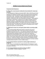
1.13 INHALE. As a soldier inhales, the outlet valve closes on the outlet<br />
valve seat to maintain a facial seal. The vacuum causes outside air to pass<br />
through the canister, which filters out contaminated air. Filtered air then<br />
travels through the hose and past the inlet valve disk into the facepiece<br />
eye cavity. Once in the eye cavity, the filtered air flows over the inside<br />
of the eyelenses to reduce fogging and past the nosecup valves into the<br />
nosecup. Some air may enter the nosecup by flowing between the nosecup and<br />
the nose/chin area, but most will enter through the nosecup valve disks.<br />
Once the filtered air enters the nosecup, the air enters the soldier's<br />
respiratory system.<br />
AIR<br />
CANISTER<br />
INLET<br />
VALVE<br />
DISK<br />
FACEPIECE<br />
EYE<br />
CAVITY<br />
NOSECUP<br />
VALVE<br />
DISK<br />
NOSECUP<br />
SOLDIER'S<br />
RESPIRATORY<br />
SYSTEM<br />
1-9
<strong>TM</strong> 3-<strong>4240</strong>-<strong>341</strong>-20&P<br />
1.14 EXHALE. As the soldier exhales, the inlet valve disk seats against the<br />
inlet valve body. Also, the nosecup valve disks seat against the nosecup valve<br />
seats to prevent exhaled air from entering the eye cavity which results in<br />
fogging of the eyelenses. Exhaled air is then directed to the outlet valve<br />
disk, which is forced open. The overall result of the outlet disk valve<br />
opening and nosecup and inlet disk valves closing is that the facial seal is<br />
maintained. Exhaled air flows past the outlet valve disk and into the outlet<br />
valve cover, where it is directed outside the mask.<br />
SOLDIER'S<br />
RESPIRATORY<br />
SYSTEM<br />
NOSECUP<br />
OUTLET<br />
VALVE<br />
DISK<br />
OUTLET<br />
VALVE<br />
COVER<br />
OUTSIDE MASK<br />
1.15 ADDITIONAL FEATURES. The M45 mask also provides the user with face-toface,<br />
phone and aircraft communication capabilities as well as a drinking<br />
capability. Face-to-face and phone communication is provided by<br />
voicemitters, which contain a grill and thin membrane. The grills protect<br />
the membranes, which allow sound to pass through them but not CB agents.<br />
Aircraft communication is provided by a microphone and microphone cable,<br />
which connect at the outlet valve housing. The microphone cable may be<br />
connected to the flight helmet to interface with aircraft communications.<br />
The drinking system consists of internal and external drink tubes. When<br />
connected to the M1 canteen cap, the external drink tube coupling plunger<br />
is pushed back by the cap pin. This creates an opening in the coupling, so<br />
that liquid may pass through it and into the soldier's mouth via the<br />
internal drink tube. When not in use, the plunger inside the external drink<br />
tube coupling seats to prevent air or liquids from entering the internal<br />
drink tube and facepiece.<br />
1-10
<strong>TM</strong> 3-<strong>4240</strong>-<strong>341</strong>-20&P<br />
CHAPTER 2<br />
MAINTENANCE INSTRUCTIONS<br />
Section I. REPAIR PARTS, SPECIAL TOOLS; TEST,<br />
MEASUREMENT AND DIAGNOSTIC EQUIPMENT (<strong>TM</strong>DE), AND<br />
SUPPORT EQUIPMENT<br />
2.1 COMMON TOOLS AND EQUIPMENT.<br />
For authorized common tools and equipment, refer to the Modified Table of<br />
Organization and Equipment (MTOE), Common Table of Allowances (CTA) 50-970, or<br />
CTA 8-100, as applicable to your unit.<br />
2.2 SPECIAL TOOLS, <strong>TM</strong>DE, AND SUPPORT EQUIPMENT.<br />
Special tools, <strong>TM</strong>DE, and support equipment required are listed in appendix C<br />
(Repair Parts and Special Tools List (RPSTL)) and appendix B (Maintenance<br />
Allocation Chart (MAC)).<br />
2.3 REPAIR PARTS.<br />
Repair parts are listed and illustrated in appendix C of this manual.<br />
2.4 GENERAL.<br />
Section II. SERVICE UPON RECEIPT<br />
This section contains instructions and procedures for services to be performed<br />
upon receipt of a new mask. These services include unpacking, checking<br />
unpacked equipment and installation instructions. Ten masks are individually<br />
packed in fiberboard containers that may be placed inside a large fiberboard<br />
or plywood box. Servicing Upon Receipt procedures for one M45 mask will<br />
require .2 hours to complete.<br />
2.5 TOOLS, TEST EQUIPMENT, SUPPLIES AND PARTS.<br />
Table 2-1 contains tools, test equipment, supplies and parts necessary for<br />
performing Service Upon Receipt procedures.<br />
2-1
<strong>TM</strong> 3-<strong>4240</strong>-<strong>341</strong>-20&P<br />
Table 2-1. Tools List for Service Upon Receipt of M45 Mask<br />
NOMENCLATURE CAGEC PART NUMBER NATIONAL STOCK NUMBER<br />
Knife, Pocket 81348 GGG-K-484 5110-00-240-5943<br />
Shears, Metal<br />
Cutting, Hand<br />
81348 GGG-S-291 5110-00-221-1085<br />
Shears, Straight<br />
Trimmers<br />
81348 GGG-S-00278 5110-00-293-3444<br />
2.6 SERVICE UPON RECEIPT OF MATERIEL.<br />
Table 2-2 contains instructions for performing the services required upon<br />
receipt of this equipment. These procedures will be performed by Unit<br />
Maintenance personnel. Service Upon Receipt procedures for one M45 mask will<br />
require .2 hours to complete.<br />
2-2
<strong>TM</strong> 3-<strong>4240</strong>-<strong>341</strong>-20&P<br />
Table 2-2. Service Upon Receipt For M45 Mask<br />
LOCATION ITEM ACTION REMARKS<br />
1. Outer<br />
Box,<br />
Fiberboard<br />
or Wood<br />
2. Inner<br />
Fiberboard<br />
Overpack<br />
Containers<br />
Overpack<br />
Containers<br />
M45 Mask<br />
Components<br />
Facepiece,<br />
Faceform<br />
and<br />
Hose<br />
a. Unpack box by<br />
cutting tape and<br />
banding on fiberboard<br />
boxes, or by<br />
cutting banding and<br />
prying off top of<br />
wooden boxes.<br />
b. For wooden boxes,<br />
remove or bend nails<br />
to prevent injury.<br />
c. Remove inner<br />
fiberboard overpack<br />
containers.<br />
a. Cut tape to open<br />
overpack container.<br />
b. Remove unit pack<br />
heat-sealed bag<br />
(HSB) and C2/C2A1<br />
canister can.<br />
NOTE<br />
Second skin is<br />
already installed<br />
on facepiece.<br />
Masks stored more<br />
than 30 days shall<br />
be stored with<br />
faceform in<br />
facepiece.<br />
a. Open unit pack<br />
HSB and remove<br />
carrier.<br />
b. Remove facepiece<br />
HSB from carrier.<br />
c. Remove facepiece<br />
from HSB.<br />
2-3
<strong>TM</strong> 3-<strong>4240</strong>-<strong>341</strong>-20&P<br />
Table 2-2. Service Upon Receipt For M45 Mask (CONT)<br />
LOCATION ITEM ACTION REMARKS<br />
2. Inner<br />
Fiberboard<br />
Overpack<br />
Containers<br />
Facepiece,<br />
Faceform<br />
and Hose<br />
(Cont)<br />
d. Peel off<br />
protective covers<br />
(1) from eyelenses. 1<br />
e. On facepiece (2),<br />
loosen head harness<br />
straps (3) and<br />
remove hose and<br />
faceform. The<br />
faceform can be<br />
stored at<br />
organizational<br />
level.<br />
2<br />
3<br />
Canister<br />
Can<br />
Other<br />
Components<br />
NOTE<br />
Do not open C2/C2A1<br />
canister can (4)<br />
until issued.<br />
Record lot numbers<br />
in accordance with<br />
unit SOP.<br />
Remove packaging<br />
from the remaining<br />
mask components<br />
inside carrier<br />
pockets (5).<br />
5<br />
4<br />
2-4
<strong>TM</strong> 3-<strong>4240</strong>-<strong>341</strong>-20&P<br />
Table 2-2. Service Upon Receipt For M45 Mask (CONT)<br />
LOCATION ITEM ACTION REMARKS<br />
3. M45 Mask M45 Mask a. Inspect equipment<br />
for damage incurred<br />
during shipment. If<br />
equipment is<br />
damaged, report the<br />
damage on Standard<br />
Form 361,<br />
Transportation<br />
Discrepancy Report.<br />
b. Record<br />
alphanumeric serial<br />
number (6) on the<br />
facepiece and<br />
provide it to your<br />
unit Property Book<br />
Officer (PBO).<br />
6<br />
4.Facepiece Outserts Install outserts on<br />
facepiece.<br />
See <strong>TM</strong> 3-<strong>4240</strong>-<strong>341</strong>-10.<br />
Microphone<br />
Cable<br />
Install microphone<br />
cable through boot<br />
on outlet valve<br />
cover, into<br />
receptacle on outlet<br />
valve housing.<br />
See para 2.14.2.2.<br />
Faceform Install Faceform (7)<br />
in facepiece for<br />
storage.<br />
7<br />
Hose<br />
Assembly<br />
Install hose<br />
assembly on<br />
facepiece.<br />
See para 2.17.3.2.<br />
2-5
<strong>TM</strong> 3-<strong>4240</strong>-<strong>341</strong>-20&P<br />
Table 2-2. Service Upon Receipt For M45 Mask (CONT)<br />
LOCATION ITEM ACTION REMARKS<br />
5. Carrier Baffle<br />
Assembly<br />
Technical<br />
Manual<br />
Outserts<br />
Canister<br />
Can<br />
Stow baffle assembly<br />
inside carrier left<br />
pocket (8).<br />
Stow Operator's<br />
manual inside<br />
carrier middle<br />
pocket (9).<br />
Stow outserts in<br />
carrier right pocket<br />
(10).<br />
Stow sealed canister<br />
can in bottom rear<br />
of carrier (11).<br />
8 9 10<br />
11<br />
Facepiece<br />
and Hood<br />
a. Stow hood in back<br />
of faceform (12),<br />
under head harness.<br />
b. Tighten head<br />
harness straps (13)<br />
to hold hood in<br />
place.<br />
12 13<br />
Hose<br />
Assembly<br />
a. Feed the hose<br />
into the bottom of<br />
the carrier.<br />
b. Place the top of<br />
the facepiece over<br />
the hose and<br />
canister.<br />
2-6
2.7 IDENTIFYING AN INDIVIDUAL'S MASK.<br />
<strong>TM</strong> 3-<strong>4240</strong>-<strong>341</strong>-20&P<br />
INITIAL SETUP<br />
Materials/Parts<br />
None<br />
CAUTION<br />
Do not make permanent identification markings on the facepiece<br />
assembly or mask carrier (AR 700-84).<br />
NOTE<br />
A mask shall be used only by the soldier to whom it is issued and<br />
fitted.<br />
a. Obtain a removable tag that fits in the ID pocket (1) on the side of the<br />
carrier.<br />
b. Mark the tag to identify the user, when the mask was fitted/tested and<br />
the size nosecup used.<br />
NOTE<br />
Each unit may derive its own system. For security reasons, do not<br />
include any information that may identify the parent organization.<br />
Avoid using markings similar to those of neighboring units.<br />
c. Place the completed identification tag in the mask carrier ID plate.<br />
1<br />
2-7
<strong>TM</strong> 3-<strong>4240</strong>-<strong>341</strong>-20&P<br />
SECTION III. SIZING, FITTING AND CHECKING THE FACEPIECE<br />
2.8. SIZING AND FITTING THE FACEPIECE.<br />
INITIAL SETUP<br />
Materials/Parts<br />
None<br />
Equipment Condition<br />
Soldier seated with glasses and headgear removed.<br />
1 of each size facepiece with same size nosecup, outlet valve<br />
and hose assembly installed<br />
Head harness over front of facepiece assembly.<br />
Faceform removed from facepiece assembly.<br />
Hood and microphone assembly removed.<br />
1 of each size nosecup<br />
Personnel Required<br />
Unit maintainer<br />
Soldier (operator)<br />
2.8.1 Sizing the Facepiece<br />
WARNING<br />
Soldiers should not wear hairstyles, hair care products or facial<br />
products which could interfere with the fit of the facepiece. Male<br />
soldiers must be clean-shaven to prevent facepiece leaks.<br />
NOTE<br />
Initial facepiece fitting should be only performed by the unit level<br />
repairer.<br />
WARNING<br />
Edges of open can are sharp.<br />
a. Use key to open C2/C2A1 canister can and remove canister.<br />
b. Install canister on canister port of hose assembly or directly to<br />
facepiece hose port. Location will be in accordance with your unit SOP.<br />
2-8
<strong>TM</strong> 3-<strong>4240</strong>-<strong>341</strong>-20&P<br />
2.8. SIZING AND FITTING THE FACEPIECE (CONT).<br />
NOTE<br />
Hood, hose and canister must not be installed<br />
on facepiece for initial sizing.<br />
1<br />
c. Loosen head harness straps (1) so that strap ends<br />
are approximately 1 in. (2.5 cm) from buckles.<br />
d. Fold head harness over front of facepiece (2).<br />
e. Start with a medium size facepiece, have soldier<br />
place chin in chin cup (3) and press facepiece to face.<br />
f. Check the edge of the facepiece to ensure it is<br />
not more than 1/2 in. into the hairline and within<br />
an inch of the ear. If the mask edge is incorrect,<br />
repeat step e with a different size facepiece.<br />
g. Have soldier slip head harness over head<br />
while holding facepiece against face.<br />
2.8.2 Fitting the Facepiece<br />
2<br />
3<br />
a. Have soldier hold facepiece tightly against chin.<br />
NOTE<br />
Make sure hand does not cover outlet valve.<br />
3<br />
2<br />
1<br />
b. (Unit maintainer) Center head harness<br />
pad (1) on back of soldier's head and have soldier<br />
hold in place.<br />
c. (Unit maintainer) Place finger or thumb under<br />
buckle (2) of forehead strap (3). Then give a<br />
sharp tug until buckle feels snug. Adjust other<br />
forehead strap in same manner.<br />
d. (Unit maintainer) Repeat step c for the cheek<br />
straps (4). Pull out both cheek straps (5)<br />
approximately 2 in. to properly seat mask on face.<br />
5<br />
e. Have soldier release facepiece. Facepiece should 6<br />
not slip down. If facepiece slips, readjust forehead and cheek straps until<br />
facepiece remains in place.<br />
f. Have soldier tighten temple straps (6) by pulling on both at the same time.<br />
4<br />
2-9
<strong>TM</strong> 3-<strong>4240</strong>-<strong>341</strong>-20&P<br />
2.8. SIZING AND FITTING THE FACEPIECE (CONT).<br />
2.8.3 Checking For Fit.<br />
WARNING<br />
Soldier's life depends on proper fitting of facepiece.<br />
a. (Unit maintainer) With soldier standing, check for proper fit according to<br />
the following criteria:<br />
1. Edge of facepiece comes up on<br />
forehead but no more than 1/2 in.<br />
into hairline and within<br />
approximately 1 in. (2.5 cm) of ear.<br />
1<br />
2. Soldier's pupils are within the<br />
upper half of the eyelens (1).<br />
3. Temple straps (2) and cheek straps<br />
(3) do not cut into ears.<br />
4. Nosecup (4) sits on the top part<br />
of the nose and is comfortable.<br />
5. Bottom of facepiece does not cut<br />
into throat.<br />
4<br />
2<br />
6. Skin in front of ear and around<br />
chin is not wrinkled.<br />
NOTE<br />
3<br />
A different size nosecup will affect the position of the nosecup<br />
on the nose and the position of the facepiece on the face.<br />
b. If facepiece is difficult to fit but meets most of the criteria, try a<br />
different size nosecup. Check fit again.<br />
c. If facepiece still does not fit, check fit with a different size facepiece<br />
and perform the steps in para 2.8.2.<br />
NOTE<br />
Internal drink tube will irritate lips if it touches them during nondrinking<br />
operations.<br />
d. Ask soldier if internal drink tube touches lips. Adjust length of internal<br />
drink tube if necessary (para 2.14.6.).<br />
e. Check the facepiece for leaks (para 2.9).<br />
2-10
<strong>TM</strong> 3-<strong>4240</strong>-<strong>341</strong>-20&P<br />
2.8. SIZING AND FITTING THE FACEPIECE (CONT).<br />
2.8.4. Optional Wear. The M45 mask may be configured to accommodate left-hand<br />
firing soldiers. This change requires a left-hand nosecup (see App C, Section<br />
II) and transfer of components from one side of the mask to the other. An<br />
additional wear configuration is that of a face-mounted canister. Soldiers who<br />
do not require a hose for operational use may be able to wear a mask without a<br />
hose. This change may only be made in accordance with your unit SOP.<br />
2.8.4.1. Left-hand Firing.<br />
a. Remove hose assembly, microphone<br />
assembly and internal drink tube from<br />
mask (see para 2.17.3.1, 2.15.1. and<br />
2.14.6.1.).<br />
b. Remove right-hand nosecup (see para<br />
2.14.7.1) and obtain a left-hand<br />
nosecup of the same size.<br />
c. Remove inlet valve assembly, side<br />
voicemitter and gasket (see 2.14.8.1,<br />
and 2.14.5.1).<br />
d. Install left-hand nosecup (see<br />
2.14.7.2).<br />
e. Install inlet valve assembly in left<br />
side of facepiece, and gasket and side<br />
voicemitter in the right side of the<br />
facepiece (see para 2.14.8.2 and 2.14.5.2).<br />
f. Install microphone assembly and<br />
internal drink tube (see para 2.15.2<br />
and 2.14.6.2).<br />
g. Check the facepiece for leaks (para 2.9).<br />
2.8.4.2. Facepiece Mounted Canister.<br />
a. Remove hose assembly from facepiece<br />
(see para 2.17.3.1).<br />
b. Remove canister and baffle assembly<br />
from hose assembly (see para 2.17.1.1).<br />
c. Remove baffle from canister and install<br />
canister on facepiece (see para 2.17.2.1).<br />
d. Check the facepiece for leaks (para 2.9).<br />
2-11
<strong>TM</strong> 3-<strong>4240</strong>-<strong>341</strong>-20&P<br />
2.9. CHECKING FOR LEAKS.<br />
INITIAL SETUP<br />
Materials/Parts<br />
M41 Protection Assessment Test System (PATS)<br />
Amyl Acetate (banana oil) (Item 1, App E)<br />
Applicator (Item 2, App E)<br />
Chemical Protective Gloves (Item 14, App E)<br />
Equipment Condition<br />
Facepiece has been adjusted, sized and fitted in accordance with<br />
para 2.8.<br />
Hose and canister installed<br />
Personnel Required<br />
Unit maintainer<br />
Operator<br />
2.9.1 Checking Facepiece for Leaks.<br />
2.9.1.1 M41 Protection Assessment Test System.<br />
NOTE<br />
Use the M41 Protection Assessment Test System (PATS) to verify the fit<br />
and to check the facepiece for leaks. The M41 shall be used in<br />
accordance with the Operator's manual for the PATS. If the M41 is not<br />
available, banana oil may be used as a substitute.<br />
2.9.1.2 Amyl Acetate (Banana Oil).<br />
AMYL ACETATE/BANANA OIL<br />
a. Have soldier put on mask (para 2.8) before opening the bottle of banana<br />
oil. If soldier smells banana oil just before masking, test results will be<br />
inaccurate.<br />
b. Remove external drink tube from retainer.<br />
2-12
2.9. CHECKING FOR LEAKS (CONT).<br />
<strong>TM</strong> 3-<strong>4240</strong>-<strong>341</strong>-20&P<br />
CAUTION<br />
Do not touch facepiece with banana oil. It is a solvent and<br />
could cause the mask to deteriorate.<br />
NOTE<br />
Make sure canister and outlet valve disk are properly installed.<br />
c. Dip applicator in banana oil.<br />
d. Soldier should breath deeply through nose only. Have soldier indicate<br />
smelling banana oil by raising hand.<br />
e. Move applicator approximately 1 to 2 in. (2.5 to 5.1 cm.) from facepiece as<br />
follows:<br />
1. Have soldier turn<br />
head to left and move<br />
applicator around<br />
outer edge of<br />
facepiece.<br />
2. Have soldier turn<br />
head to right and<br />
again move applicator<br />
around outer edge of<br />
facepiece.<br />
3. Have soldier tilt head upward<br />
and turn head from side to side.<br />
Move applicator under chin around<br />
outer edge of facepiece.<br />
4. Have soldier tilt head forward.<br />
Move applicator around outer edge<br />
of facepiece.<br />
2-13
2.9. CHECKING FOR LEAKS (CONT).<br />
5. Have soldier smile and<br />
frown while looking straight<br />
ahead. Move applicator around<br />
outlet valve (1), front<br />
voicemitter (2), eyelenses (3)<br />
and completely around outer<br />
edge of facepiece.<br />
<strong>TM</strong> 3-<strong>4240</strong>-<strong>341</strong>-20&P<br />
2<br />
3<br />
6. Instruct soldier to press<br />
palm firmly over canister inlet.<br />
Have soldier breathe in,<br />
collapsing facepiece. Move<br />
applicator around outer edge of<br />
facepiece before having soldier<br />
breathe.<br />
1<br />
NOTE<br />
If soldier being tested smells banana oil during initial<br />
fitting and testing, a 5-7 minute odor sensitivity recovery<br />
period is required before retesting.<br />
f. If soldier can smell banana oil, readjust head harness to improve fit (para<br />
2.8.2) and recheck.<br />
g. If soldier smells banana oil after readjustment of head harness, retest<br />
with a different mask of the same size with the same size nosecup.<br />
h. If soldier still smells banana oil, recheck with a different size nosecup<br />
in the same mask, in a different location.<br />
i. If soldier still smells banana oil, recheck with a different size mask.<br />
j. If soldier cannot smell banana oil, have him unmask and smell the<br />
applicator to be sure his sense of smell is not impaired. If the soldier's<br />
sense of smell is impaired, the test must be conducted in a CS (tear gas)<br />
chamber.<br />
k. Install hood on facepiece (para 2.18.2).<br />
l. Aviators helmet should be refitted by the unit ALSE repairer.<br />
2-14
2.9. CHECKING FOR LEAKS (CONT).<br />
<strong>TM</strong> 3-<strong>4240</strong>-<strong>341</strong>-20&P<br />
2.9.2 Checking Drinking System for Leaks.<br />
a. Steady facepiece, withdraw external drink tube (1) from outlet valve cover<br />
and let it hang freely.<br />
b. Grasp internal drink tube (2) between teeth.<br />
1 2<br />
WARNING<br />
If you see bubbles when checking the drinking system in water, the<br />
drinking system leaks.<br />
c. Place quick disconnect coupling (1) in a cup of potable water.<br />
d. Blow into internal drink tube (2). If bubbles appear, the system is leaking<br />
(See Troubleshooting, para 2.12.).<br />
e. If bubbles do not appear, suck on internal drink tube. If water enters your<br />
mouth, the drinking system is leaking (See Troubleshooting. para 2.12.). If<br />
water does not enter your mouth, the system is operational.<br />
2-15
<strong>TM</strong> 3-<strong>4240</strong>-<strong>341</strong>-20&P<br />
SECTION IV. PREVENTIVE MAINTENANCE CHECKS AND SERVICES<br />
2.10. PREVENTIVE MAINTENANCE CHECKS AND SERVICES.<br />
INITIAL SETUP<br />
Materials/Parts<br />
Brush, Artist's (Item 4, App E)<br />
Cheesecloth (Item 10, App E)<br />
Lacquer (Item 16, App E)<br />
Light Source<br />
References<br />
<strong>TM</strong> 3-<strong>4240</strong>-<strong>341</strong>-10<br />
Equipment Condition<br />
Operator level PMCS has been<br />
performed<br />
Personnel Required<br />
Unit maintainer<br />
Operator (Soldier)<br />
2.10.1 General. Perform unit PMCS on the M45 mask semiannually (every 6<br />
months). The operator may perform unit PMCS under the supervision of unit<br />
maintenance personnel. Semiannual PMCS will be scheduled on DD Form 314,<br />
Preventative Maintenance Schedule and Record.<br />
2.10.2 PMCS Procedures. This PMCS table lists those required checks and<br />
services necessary to ensure the masks are in condition to safely perform<br />
their missions.<br />
2.10.3 Explanation of Columns of the PMCS Schedule.<br />
(1) Item Number. Checks and services are numbered in order of<br />
performance. Use this as a source for the <strong>TM</strong> Number Column on DA Form<br />
2404, Equipment Inspection and Maintenance Worksheet, in recording<br />
results of PMCS.<br />
(2) Interval. This column describes how often PMCS is to be performed.<br />
(3) Item to Be Checked Or Serviced. The items listed in this column are<br />
divided into groups indicating portions of the equipment. The name<br />
corresponds to that used in the Maintenance Allocation Chart (App B,<br />
Sect II).<br />
(4) Procedure. This column briefly describes the procedures for<br />
performing the check or service. Whenever replacement or repair is<br />
recommended, reference is made to paragraph number for the applicable<br />
maintenance instruction.<br />
(5) Not Fully Mission Capable If. This column contains a brief<br />
description of the condition that causes the equipment to be less than<br />
fully ready to perform the assigned mission.<br />
2-16
<strong>TM</strong> 3-<strong>4240</strong>-<strong>341</strong>-20&P<br />
Table 2-3. Preventative Maintenance Checks and Services for the M45 Mask<br />
ITEM ITEM TO BE NOT FULLY<br />
NO. INTERVAL CHECKED OR PROCEDURE MISSION<br />
SERVICED<br />
CAPABLE IF:<br />
1 Semiannually<br />
Canister<br />
CAUTION<br />
Care must be taken not to<br />
scratch eyelenses or outserts<br />
when handling the mask.<br />
a. Remove canister (1) from hose<br />
assembly (2) (or facepiece) by<br />
rotating canister counterclockwise.<br />
2<br />
3<br />
1<br />
b. If present, remove baffle (3)<br />
from canister (see para<br />
2.17.2.1). Shake canister and<br />
listen for loose particles.<br />
c. Check baffle assembly for<br />
frays, cuts, cracks and breaks.<br />
d. Check canister against<br />
canister replacement criteria (FM<br />
3-4).<br />
Particles<br />
rattle or<br />
dust falls out<br />
of canister.<br />
Baffle is<br />
damaged.<br />
Canister is<br />
unserviceable.<br />
2-17
<strong>TM</strong> 3-<strong>4240</strong>-<strong>341</strong>-20&P<br />
Table 2-3. Preventative Maintenance Checks and Services for the M45 Mask<br />
ITEM ITEM TO BE NOT FULLY<br />
NO. INTERVAL CHECKED OR PROCEDURE MISSION<br />
SERVICED<br />
CAPABLE IF:<br />
2 Semiannually<br />
Hose<br />
Assembly<br />
a. Reverse hood.<br />
b. Remove hose assembly (1) from<br />
facepiece (2) by rotating star<br />
knob (3) counterclockwise.<br />
c. Remove port gasket (4) from<br />
canister port (5), and check for<br />
dirt, cuts, tears and distortion.<br />
Port gasket is<br />
damaged.<br />
2<br />
3<br />
1<br />
4<br />
6<br />
5<br />
d. Check threads on canister port<br />
(5) and star knob swivel (3) for<br />
dirt, nicks and cracks.<br />
Threads are<br />
damaged.<br />
e. Reinstall port gasket (4).<br />
f. Check hose retaining clip (6)<br />
for fraying, bends, bare metal<br />
and loss of holding power.<br />
g. While holding hose in one<br />
hand, pull on star knob swivel<br />
(3) to ensure that it is secure.<br />
Hose clip is<br />
damaged or<br />
unserviceable.<br />
Star knob<br />
swivel or<br />
canister port<br />
is loose on<br />
hose.<br />
h. Repeat step g for the canister<br />
port (5).<br />
2-18
<strong>TM</strong> 3-<strong>4240</strong>-<strong>341</strong>-20&P<br />
Table 2-3. Preventative Maintenance Checks and Services for the M45 Mask<br />
ITEM ITEM TO BE NOT FULLY<br />
NO. INTERVAL CHECKED OR PROCEDURE MISSION<br />
SERVICED<br />
CAPABLE IF:<br />
3 Semiannually<br />
Microphone<br />
Cable<br />
CAUTION<br />
Grasp microphone cable by the<br />
the ends only. Do not pull on<br />
wire during removal.<br />
a. Remove microphone cable (1)<br />
from facepiece by grasping near<br />
boot (2) on outlet valve cover<br />
(3) and pulling.<br />
2<br />
3<br />
1<br />
b. Check microphone cable for<br />
cuts or exposed wires.<br />
c. Check ends of microphone cable<br />
for dirt, cracks and bent pins.<br />
Microphone<br />
cable is cut<br />
or has exposed<br />
wires.<br />
Microphone<br />
cable ends are<br />
cracked or<br />
contain bent<br />
pins.<br />
2-19
<strong>TM</strong> 3-<strong>4240</strong>-<strong>341</strong>-20&P<br />
Table 2-3. Preventative Maintenance Checks and Services for the M45 Mask<br />
ITEM ITEM TO BE NOT FULLY<br />
NO. INTERVAL CHECKED OR PROCEDURE MISSION<br />
SERVICED<br />
CAPABLE IF:<br />
4 Semiannually<br />
External<br />
Drink Tube<br />
a. Remove quick disconnect<br />
coupling (QDC)(1) from retainer<br />
(2) on outlet valve cover (3).<br />
4<br />
3<br />
5<br />
2<br />
1<br />
b. Grasp attached end of drink<br />
tube (4) near outlet valve cover<br />
and pull to remove.<br />
c. Check external drink tube (5)<br />
for cracks and cuts.<br />
d. Check that QDC is securely<br />
attached to external drink tube<br />
(4).<br />
e. Check that QDC is not bent or<br />
dented.<br />
External drink<br />
tube is cut or<br />
cracked.<br />
QDC is loose<br />
on external<br />
drink tube.<br />
QDC is dented<br />
or bent.<br />
2-20
<strong>TM</strong> 3-<strong>4240</strong>-<strong>341</strong>-20&P<br />
Table 2-3. Preventative Maintenance Checks and Services for the M45 Mask<br />
ITEM ITEM TO BE NOT FULLY<br />
NO. INTERVAL CHECKED OR PROCEDURE MISSION<br />
SERVICED<br />
CAPABLE IF:<br />
5 Semiannually<br />
Outlet<br />
Valve<br />
Cover,<br />
Disk and<br />
Housing<br />
a. Remove outlet valve cover (1)<br />
(See para 2.14.3.1.).<br />
3<br />
4<br />
2<br />
1<br />
5<br />
b. Check outlet valve cover (1)<br />
for dirt, holes and tears.<br />
c. Check outlet valve disk (2)<br />
for dirt, holes, tears and<br />
distortion.<br />
d. Check drink tube connector<br />
(3), electrical receptacle (4),<br />
outlet valve seat (5) and outlet<br />
valve housing for dirt, nicks and<br />
cracks.<br />
Outlet valve<br />
cover is<br />
damaged.<br />
Outlet valve<br />
disk damaged.<br />
Electrical<br />
receptacle,<br />
drink tube<br />
connector or<br />
outlet valve<br />
housing is<br />
damaged.<br />
2-21
<strong>TM</strong> 3-<strong>4240</strong>-<strong>341</strong>-20&P<br />
Table 2-3. Preventative Maintenance Checks and Services for the M45 Mask<br />
ITEM ITEM TO BE NOT FULLY<br />
NO. INTERVAL CHECKED OR PROCEDURE MISSION<br />
SERVICED<br />
CAPABLE IF:<br />
6 Semiannually<br />
Hood<br />
CAUTION<br />
Holding hood too close to<br />
light source may result in<br />
damage to hood.<br />
a. Remove hood (1) by loosening<br />
drawstrings (2), and expanding<br />
opening (3) of the hood.<br />
3<br />
1<br />
2<br />
b. Check material around opening<br />
and drawstrings for tears, cuts<br />
and holes.<br />
c. Inspect hood (1) by holding in<br />
front of light source. Look for<br />
the following deficiencies:<br />
Hood has<br />
tears, cuts or<br />
holes.<br />
Hood is<br />
damaged.<br />
> Tears, cuts or holes.<br />
> Peeled or worn coating.<br />
> Loose seams.<br />
Turn hood (1) inside out and<br />
repeat steps b and c.<br />
2-22
<strong>TM</strong> 3-<strong>4240</strong>-<strong>341</strong>-20&P<br />
Table 2-3. Preventative Maintenance Checks and Services for the M45 Mask<br />
ITEM ITEM TO BE NOT FULLY<br />
NO. INTERVAL CHECKED OR PROCEDURE MISSION<br />
SERVICED<br />
CAPABLE IF:<br />
7 Semiannually<br />
Second<br />
Skin<br />
a. Remove outserts by grasping<br />
tabs (1) and pulling.<br />
1<br />
CAUTION<br />
Holding second skin too close<br />
to light source may result in<br />
damage to second skin.<br />
During removal, use extreme<br />
caution when stretching second<br />
in around faceblank assembly<br />
components. Second skin could<br />
catch and tear.<br />
b. Remove second skin (2) as<br />
follows:<br />
(1) Stretch eyelens openings<br />
around and over eyerings (3).<br />
3<br />
2<br />
2-23
<strong>TM</strong> 3-<strong>4240</strong>-<strong>341</strong>-20&P<br />
Table 2-3. Preventative Maintenance Checks and Services for the M45 Mask<br />
ITEM ITEM TO BE NOT FULLY<br />
NO. INTERVAL CHECKED OR PROCEDURE MISSION<br />
SERVICED<br />
CAPABLE IF:<br />
7 Semiannual<br />
Second<br />
Skin<br />
(cont)<br />
(2) Stretch and pull second<br />
skin openings over side<br />
voicemitter (4), front<br />
voicemitter (5), outlet valve<br />
housing (6) and hose assembly<br />
port (7).<br />
4<br />
7<br />
5 6<br />
c. Check second skin for dirt.<br />
d. Inspect second skin for holes,<br />
tears and splits by holding in<br />
front of light source.<br />
e. Check rest of second skin for<br />
stiff areas that crumble when<br />
rubbed between fingers and cracks<br />
which expand when rubber is<br />
stretched.<br />
Second skin<br />
has holes,<br />
tears or<br />
splits.<br />
Second skin is<br />
damaged.<br />
2-24
<strong>TM</strong> 3-<strong>4240</strong>-<strong>341</strong>-20&P<br />
Table 2-3. Preventative Maintenance Checks and Services for the M45 Mask<br />
ITEM ITEM TO BE NOT FULLY<br />
NO. INTERVAL CHECKED OR PROCEDURE MISSION<br />
SERVICED<br />
CAPABLE IF:<br />
8 Semiannually<br />
Side<br />
Voicemitter<br />
Ensure that side voicemitter (1)<br />
is handtight by screwing<br />
clockwise with flat side of<br />
carrier D-ring (2), or star knob<br />
swivel.<br />
Side<br />
voicemitter<br />
is loose.<br />
2<br />
1<br />
2-25
<strong>TM</strong> 3-<strong>4240</strong>-<strong>341</strong>-20&P<br />
Table 2-3. Preventative Maintenance Checks and Services for the M45 Mask<br />
ITEM ITEM TO BE NOT FULLY<br />
NO. INTERVAL CHECKED OR PROCEDURE MISSION<br />
SERVICED<br />
CAPABLE IF:<br />
9 Semiannually<br />
Head<br />
Harness<br />
a. Check straps for bent or<br />
missing clips (1). For head<br />
harness replacement see para<br />
2.14.1.1.<br />
Clips are bent<br />
or missing.<br />
1<br />
LACQUER<br />
b. Make sure head harness strap<br />
clips (1) are covered with black<br />
lacquer. Coat all bare metal<br />
surfaces using brush (Item 4, App<br />
E) and lacquer (Item 16, App E).<br />
2-26
<strong>TM</strong> 3-<strong>4240</strong>-<strong>341</strong>-20&P<br />
Table 2-3. Preventative Maintenance Checks and Services for the M45 Mask<br />
ITEM ITEM TO BE NOT FULLY<br />
NO. INTERVAL CHECKED OR PROCEDURE MISSION<br />
SERVICED<br />
CAPABLE IF:<br />
10 Semi-<br />
Annually<br />
Internal<br />
Drink Tube<br />
a. Remove internal drink tube (1)<br />
by grasping near connection to<br />
outlet valve housing (2) and pull<br />
up.<br />
1<br />
2<br />
b. Check for cuts, cracks and<br />
holes.<br />
c. Blow through drink tube to<br />
check for clogs.<br />
Internal drink<br />
tube contains<br />
cuts, cracks<br />
or holes.<br />
Internal drink<br />
tube is<br />
clogged.<br />
2-27
<strong>TM</strong> 3-<strong>4240</strong>-<strong>341</strong>-20&P<br />
Table 2-3. Preventative Maintenance Checks and Services for the M45 Mask<br />
ITEM ITEM TO BE NOT FULLY<br />
NO. INTERVAL CHECKED OR PROCEDURE MISSION<br />
SERVICED<br />
CAPABLE IF:<br />
11 Semiannually<br />
Microphone<br />
Assembly<br />
Ensure microphone assembly (1) is<br />
seated and securely attached to<br />
outlet valve housing (2).<br />
Microphone<br />
positioner<br />
will not seat<br />
securely.<br />
1<br />
2<br />
2-28
<strong>TM</strong> 3-<strong>4240</strong>-<strong>341</strong>-20&P<br />
Table 2-3. Preventative Maintenance Checks and Services for the M45 Mask<br />
ITEM ITEM TO BE NOT FULLY<br />
NO. INTERVAL CHECKED OR PROCEDURE MISSION<br />
SERVICED<br />
CAPABLE IF:<br />
12 Semiannually<br />
Inlet<br />
Valve<br />
Assembly<br />
a. Remove inlet valve assembly<br />
(1) from facepiece (para<br />
2.14.8.1.).<br />
2<br />
1<br />
b. Check inlet valve port (2) for<br />
dirt, cracks, nicks or breaks.<br />
Inlet valve<br />
port is<br />
damaged.<br />
5 4 3<br />
c. Check valve body (3) and valve<br />
disk (4) for dirt, cuts, tears<br />
and holes.<br />
d. Check that cage (5) will<br />
securely mount to valve body (3).<br />
e. Check cage (5) for dirt,<br />
cracks, nicks or breaks.<br />
Valve body or<br />
disk is<br />
damaged.<br />
Cage will not<br />
mount to valve<br />
body.<br />
Cage is<br />
damaged.<br />
2-29
<strong>TM</strong> 3-<strong>4240</strong>-<strong>341</strong>-20&P<br />
Table 2-3. Preventative Maintenance Checks and Services for the M45 Mask<br />
ITEM ITEM TO BE NOT FULLY<br />
NO. INTERVAL CHECKED OR PROCEDURE MISSION<br />
SERVICED<br />
CAPABLE IF:<br />
13 Semiannually<br />
Facepiece<br />
a. Check facepiece (1) for<br />
deformities which may affect fit<br />
and seal to the face.<br />
1<br />
2<br />
Facepiece is<br />
difficult to<br />
open or<br />
unusually<br />
stiff in<br />
sealing<br />
surfaces.<br />
3<br />
LACQUER<br />
b. Check facepiece strap buckles<br />
(2) for bare metal. Coat bare<br />
metal surfaces with brush and<br />
lacquer (Item 4 and 16, App E).<br />
c. Grasp facepiece strap buckle<br />
between thumb and forefinger.<br />
Pull facepiece straps (3) until<br />
it stretches 1/2 inch to 3/4<br />
inches (1/3 cm to 1.9 cm). Check<br />
for weakness and tears. Repeat<br />
check for all facepiece straps.<br />
Facepiece<br />
straps are<br />
torn or have<br />
lost their<br />
elasticity.<br />
d. Check rest of facepiece for<br />
dirt, cuts, tears, holes and<br />
stiff areas that have lost their<br />
elasticity.<br />
Facepiece is<br />
damaged.<br />
2-30
<strong>TM</strong> 3-<strong>4240</strong>-<strong>341</strong>-20&P<br />
Table 2-3. Preventative Maintenance Checks and Services for the M45 Mask<br />
ITEM ITEM TO BE NOT FULLY<br />
NO. INTERVAL CHECKED OR PROCEDURE MISSION<br />
SERVICED<br />
CAPABLE IF:<br />
13 Semiannually<br />
Facepiece<br />
(cont)<br />
e. Reassemble the following<br />
components to the faceblank<br />
assembly: second skin (para<br />
2.14.9.2.), outserts, inlet valve<br />
assembly (para 2.14.8.2.) and<br />
internal drink tube (para<br />
2.14.6.2.).<br />
f. Reassemble outlet valve cover:<br />
(1) Work external drink tube (4)<br />
through hole on top of outlet<br />
valve cover (5).<br />
4<br />
7<br />
5<br />
6<br />
14 Semiannually<br />
Mask<br />
(2) Feed microphone cable (6)<br />
through boot (7) on top of outlet<br />
valve cover.<br />
(3) Install external drink tube,<br />
microphone cable and outlet valve<br />
cover to faceblank assembly.<br />
a. Assemble hood to facepiece<br />
(para 2.18.2).<br />
b. Install hose assembly to<br />
facepiece (para 2.17.3.2.).<br />
c. Install canister and baffle on<br />
hose assembly (para 2.17.2.2.).<br />
d. Refit facepiece (para 2.8.2).<br />
e. Perform leak check (para 2.9). Mask leaks.<br />
2-31
2.11. CANISTER REPLACEMENT CRITERIA.<br />
<strong>TM</strong> 3-<strong>4240</strong>-<strong>341</strong>-20&P<br />
In peacetime, canisters can be used until they become difficult to breathe<br />
through or they are damaged enough that a seal cannot be obtained. See FM 3-4,<br />
NBC Protection, for detailed canister replacement criteria. Turn in used or<br />
unusable canisters in accordance with local SOP.<br />
NOTE<br />
Excluding seams and thread surfaces, canister dents<br />
less than 1/4 inch deep are acceptable.<br />
2-32
2.12. TROUBLESHOOTING PROCEDURES.<br />
<strong>TM</strong> 3-<strong>4240</strong>-<strong>341</strong>-20&P<br />
SECTION V. TROUBLESHOOTING<br />
2.12.1. Description of Troubleshooting Flowchart. The following describes the<br />
use of the troubleshooting procedures.<br />
INPUT<br />
Required action.<br />
Perform in sequence<br />
indicated.<br />
NO<br />
DECISION<br />
Equipment<br />
Indication.<br />
YES<br />
ACTION<br />
Perform these repair<br />
procedures and repeat<br />
the test as indicated,<br />
to ensure trouble is<br />
corrected.<br />
ACTION<br />
Required action.<br />
2.12.2. Symptom Index. Perform functional test first. Then use symptom index<br />
for quick access to the troubleshooting procedures.<br />
a. Insufficient Air To User……………………………………………………………………………………………2-34<br />
b. Facepiece Fails To Seal………………………………………………………………………………………………2-35<br />
c. Eyelenses Fog Excessively…………………………………………………………………………………………2-37<br />
d. Communication System Inoperative………………………………………………………………………2-38<br />
e. Drinking System Inoperative……………………………………………………………………………………2-40<br />
f. Drinking System Leaks……………………………………………………………………………………………………2-42<br />
2-33
<strong>TM</strong> 3-<strong>4240</strong>-<strong>341</strong>-20&P<br />
2.12. TROUBLESHOOTING PROCEDURES (CONT).<br />
INSUFFICIENT<br />
AIR TO USER<br />
NO<br />
IS CANISTER<br />
CLOGGED?<br />
YES<br />
CHECK NOSECUP<br />
VALVE DISK<br />
REPLACE CANISTER<br />
& RECHECK<br />
(PARA 2.17.1)<br />
NO<br />
IS NOSECUP<br />
VALVE DISK<br />
STICKING?<br />
YES<br />
CHECK HOSE<br />
ASSEMBLY<br />
RESEAT NOSECUP<br />
VALVE DISK AND<br />
RECHECK<br />
NO<br />
IS HOSE<br />
BLOCKED?<br />
YES<br />
CHECK INLET<br />
VALVE DISK<br />
REPLACE HOSE<br />
AND RECHECK<br />
(PARA 2.17.3)<br />
NO<br />
IS DISK STICKING<br />
OR INSTALLED<br />
INCORRECTLY?<br />
YES<br />
CHECK OUTLET<br />
VALVE DISK<br />
REPLACE INLET VALVE<br />
ASSEMBLY AND RECHECK<br />
(PARA 2.14.8.)<br />
NO<br />
IS OUTLET VALVE<br />
DISK STICKING?<br />
YES<br />
REPLACE NOSECUP<br />
ASSEMBLY AND RECHECK<br />
(PARA 2.14.7.)<br />
RESEAT/REPLACE OUTLET<br />
VALVE DISK AND RECHECK<br />
(PARA 2.14.4.)<br />
2-34
<strong>TM</strong> 3-<strong>4240</strong>-<strong>341</strong>-20&P<br />
2.12. TROUBLESHOOTING PROCEDURES (CONT).<br />
FACEPIECE<br />
FAILS TO SEAL<br />
NO<br />
IS FACEPIECE<br />
PROPERLY FITTED?<br />
YES<br />
REFIT FACEPIECE<br />
AND RECHECK<br />
(PARA 2.8.)<br />
CHECK OUTLET<br />
VALVE<br />
NO<br />
IS OUTLET<br />
VALVE DISK<br />
SERVICEABLE?<br />
YES<br />
REPLACE OUTLET VALVE<br />
DISK AND RECHECK<br />
(PARA 2.14.4.)<br />
CHECK<br />
CANISTER<br />
NO<br />
IS CANISTER<br />
DAMAGED OR LOOSE<br />
ON HOSE ASSEMBLY?<br />
YES<br />
CHECK PORT<br />
GASKET<br />
TIGHTEN/REPLACE<br />
CANISTER AND RECHECK<br />
(PARA 2.17.1.)<br />
NO<br />
IS PORT GASKET<br />
DAMAGED OR NOT<br />
SEATED PROPERLY?<br />
YES<br />
CHECK HOSE<br />
ASSEMBLY<br />
INSTALL/REPLACE<br />
PORT GASKET AND RECHECK<br />
(PARA 2.17.1.)<br />
CONTINUED ON NEXT PAGE<br />
2-35
<strong>TM</strong> 3-<strong>4240</strong>-<strong>341</strong>-20&P<br />
2.12. TROUBLESHOOTING PROCEDURES (CONT).<br />
CHECK HOSE<br />
ASSEMBLY<br />
NO<br />
IS HOSE ASSEMBLY<br />
DAMAGED OR LOOSE<br />
ON FACEPIECE?<br />
YES<br />
CHECK INLET<br />
ASSEMBLY<br />
TIGHTEN/REPLACE<br />
HOSE ASSEMBLY<br />
AND RECHECK<br />
(PARA 2.17.3.)<br />
NO<br />
IS INLET VALVE<br />
ASSEMBLY SEATED<br />
AND SERVICEABLE?<br />
YES<br />
SEAT/REPLACE INLET VALVE<br />
ASSEMBLY AND RECHECK<br />
(PARA 2.14.8.)<br />
CHECK EXTERNAL<br />
DRINK TUBE<br />
NO<br />
IS EXTERNAL DRINK<br />
TUBE DAMAGED OR<br />
LOOSE ON FACEPIECE?<br />
YES<br />
CHECK SIDE<br />
VOICEMITTER<br />
AND GASKET<br />
INSTALL/REPLACE EXTERNAL<br />
DRINK TUBE AND RECHECK<br />
(PARA 2.16.2.)<br />
NO<br />
ARE VOICEMITTER AND<br />
GASKET SERVICEABLE<br />
AND SEATED PROPERLY?<br />
YES<br />
INSTALL/REPLACE SIDE<br />
VOICEMITTER OR GASKET<br />
AND RECHECK<br />
(PARA 2.14.5.)<br />
REPLACE FACEBLANK<br />
ASSEMBLY<br />
(PARA 2.14.9.)<br />
2-36
<strong>TM</strong> 3-<strong>4240</strong>-<strong>341</strong>-20&P<br />
2.12. TROUBLESHOOTING PROCEDURES (CONT).<br />
EYELENSES FOG<br />
EXCESSIVELY<br />
NO<br />
ARE OUTSERTS<br />
MISSING OR<br />
DAMAGED?<br />
YES<br />
CHECK INLET<br />
VALVE ASSEMBLY<br />
REPLACE OUTSERTS<br />
AND RECHECK<br />
(<strong>TM</strong> 3-<strong>4240</strong>-<strong>341</strong>-10)<br />
NO<br />
IS INLET VALVE<br />
ASSEMBLY DAMAGED<br />
OR MISSING?<br />
YES<br />
CHECK NOSECUP<br />
ASSEMBLY<br />
REPLACE INLET VALVE<br />
ASSEMBLY AND RECHECK<br />
(PARA 2.14.8.)<br />
NO<br />
IS NOSECUP ASSEMBLY<br />
SERVICEABLE AND SEATED?<br />
ARE NOSECUP VALVES ON THE<br />
SAME SIDE OF THE FACEPIECE<br />
AS THE SIDE VOICEMITTER?<br />
YES<br />
INSTALL/REPLACE<br />
NOSECUP ASSEMBLY<br />
AND RECHECK<br />
(PARA 2.14.7.)<br />
CHECK FIT OF NOSECUP<br />
ON SOLDIER’S FACE<br />
(PARA 2.8.)<br />
NO<br />
DOES NOSECUP<br />
ASSEMBLY SEAL TO<br />
SOLDIER’S CHIN<br />
AND NOSE?<br />
YES<br />
REPLACE NOSECUP<br />
ASSEMBLY WITH DIFFERENT<br />
SIZE AND RECHECK<br />
(PARA 2.14.7.)<br />
REPLACE FACEBLANK<br />
ASSEMBLY<br />
(PARA 2.14.9.)<br />
2-37
<strong>TM</strong> 3-<strong>4240</strong>-<strong>341</strong>-20&P<br />
2.12. TROUBLESHOOTING PROCEDURES (CONT).<br />
NOTE<br />
COMMUNICATION<br />
SYSTEM<br />
INOPERATIVE<br />
Use the smallest<br />
ohmmeter graduation for<br />
continuity checks.<br />
NO<br />
IS MICROPHONE<br />
CABLE LOOSE<br />
OR DAMAGED?<br />
YES<br />
CHECK OUTLET<br />
VALVE HOUSING<br />
INSTALL/REPLACE<br />
MICROPHONE CABLE<br />
AND RECHECK<br />
(PARA 2.14.2.)<br />
NO<br />
IS MICROPHONE<br />
CABLE RECEPTACLE<br />
DAMAGED?<br />
YES<br />
CHECK MICROPHONE<br />
ASSEMBLY<br />
REPLACE FACEBLANK<br />
ASSEMBLY<br />
(PARA 2.14.9.)<br />
NO<br />
IS MICROPHONE POSITIONER<br />
LOOSE, DAMAGED, OR<br />
MISSING GASKET?<br />
YES<br />
NO<br />
IS THERE A<br />
SHORT IN THE<br />
MICROPHONE<br />
ASSEMBLY?<br />
YES<br />
INSTALL/REPLACE<br />
MICROPHONE POSITIONER<br />
(PARA 2.15.)<br />
CHECK MICROPHONE<br />
PASS THROUGH<br />
REPLACE<br />
MICROPHONE AND<br />
RECHECK<br />
(PARA 2.15.)<br />
CONTINUED ON NEXT PAGE<br />
2-38
<strong>TM</strong> 3-<strong>4240</strong>-<strong>341</strong>-20&P<br />
2.12. TROUBLESHOOTING PROCEDURES (CONT).<br />
CHECK MICROPHONE<br />
PASS THROUGH<br />
NO<br />
IS THERE A SHORT<br />
WITHIN THE<br />
MICROPHONE PASS<br />
THROUGH?<br />
YES<br />
CHECK MICROPHONE<br />
CABLE<br />
REPLACE FACEBLANK<br />
ASSEMBLY<br />
(PARA 2.14.9.)<br />
NO<br />
IS THERE A SHORT<br />
WITHIN THE<br />
MICROPHONE CABLE?<br />
YES<br />
REPLACE MICROPHONE<br />
ASSEMBLY AND RECHECK<br />
(PARA 2.15.)<br />
REPLACE MICROPHONE<br />
CABLE AND RECHECK<br />
(PARA 2.14.2.)<br />
2-39
<strong>TM</strong> 3-<strong>4240</strong>-<strong>341</strong>-20&P<br />
2.12. TROUBLESHOOTING PROCEDURES (CONT).<br />
DRINKING SYSTEM<br />
INOPERATIVE<br />
NO<br />
PUSH DOWN EXTERNAL<br />
DRINK TUBE PLUNGER<br />
WITH A SCREWDRIVER.<br />
(ITEM 18, APP E)<br />
DOES PLUNGER MOVE?<br />
YES<br />
CHECK EXTERNAL<br />
DRINK TUBE<br />
REPLACE QUICK<br />
DISCONNECT AND<br />
RECHECK<br />
(PARA 2.16.1.)<br />
NO<br />
REMOVE EXTERNAL DRINK<br />
TUBE FROM HOUSING AND<br />
CONECT TO M1 CANTEEN<br />
CAP. WITH CAP OPEN,<br />
BLOW AIR INTO OPEN<br />
END OF TUBE. CAN AIR<br />
PASS THROUGH?<br />
YES<br />
NO<br />
REPLACE QDC<br />
(PARA 2.16.1.)<br />
SEPARATE QUICK DISCONNECT<br />
COUPLING (QDC) FROM M1<br />
CANTEEN CAP. CHECK<br />
EXTERNAL DRINK TUBE.<br />
SEPARATE QDC<br />
FROM DRINK<br />
TUBE, AND BLOW<br />
AIR INTO TUBE.<br />
CAN AIR PASS<br />
THROUGH?<br />
YES<br />
REPLACE EXTERNAL<br />
DRINK TUBE<br />
(PARA 2.16.2.)<br />
NO<br />
REPLACE INTERNAL<br />
DRINK TUBE<br />
(PARA 2.14.6.)<br />
CHECK INTERNAL<br />
DRINK TUBE<br />
REMOVE INTERNAL<br />
DRINK TUBE.<br />
BLOW AIR INTO<br />
TUBE. CAN AIR<br />
PASS THROUGH?<br />
YES<br />
CHECK OUTLET<br />
VALVE HOUSING<br />
CONTINUED ON NEXT PAGE<br />
2-40
<strong>TM</strong> 3-<strong>4240</strong>-<strong>341</strong>-20&P<br />
2.12. TROUBLESHOOTING PROCEDURES (CONT).<br />
NO<br />
INSTALL INTERNAL DRINK<br />
TUBE. TRY TO FORCE<br />
BLOCKAGE OUT BY BLOWING<br />
THROUGH TUBE. CAN AIR<br />
PASS THROUGH?<br />
YES<br />
REPLACE<br />
FACEBLANK<br />
(PARA 2.14.9.)<br />
ASSEMBLE FACEPIECE<br />
AND RECHECK<br />
(PMCS ITEM 13)<br />
2-41
<strong>TM</strong> 3-<strong>4240</strong>-<strong>341</strong>-20&P<br />
2.12. TROUBLESHOOTING PROCEDURES (CONT).<br />
DRINKING SYSTEM<br />
LEAKS<br />
NO<br />
PUSH DOWN EXTERNAL<br />
DRINK TUBE PLUNGER<br />
WITH SCREWDRIVER<br />
(ITEM 18, APP E).<br />
DOES PLUNGER MOVE?<br />
YES<br />
REPLACE QUICK<br />
DISCONNECT COUPLING<br />
AND RECHECK<br />
(PARA 2.16.1.)<br />
CHECK EXTERNAL<br />
DRINK TUBE<br />
NO<br />
REMOVE EXTERNAL DRINK<br />
TUBE AND BLOW AIR INTO<br />
OPEN END OF TUBE. CAN<br />
AIR PASS THROUGH?<br />
YES<br />
CHECK INTERNAL<br />
DRINK TUBE<br />
REPLACE EXTERNAL<br />
DRINK TUBE AND<br />
RECHECK<br />
(PARA 2.16.2.)<br />
NO<br />
REMOVE INTERNAL DRINK<br />
TUBE AND BLOW AIR INTO<br />
OPEN END OF TUBE WHILE<br />
PINCHING THE OTHER END.<br />
CAN AIR PASS THROUGH?<br />
YES<br />
REPLACE<br />
FACEBLANK<br />
(PARA 2.14.9.)<br />
REPLACE INTERNAL<br />
DRINK TUBE AND<br />
RECHECK<br />
(PARA 2.14.6.)<br />
2-42
<strong>TM</strong> 3-<strong>4240</strong>-<strong>341</strong>-20&P<br />
SECTION VI. MAINTENANCE PROCEDURES<br />
2.13. GENERAL.<br />
CAUTION<br />
DO NOT scratch eyelenses while performing maintenance procedures.<br />
NOTE<br />
Hood, hose assembly and microphone cable not shown for clarity.<br />
The maintenance procedures in this section are to be performed by a unit<br />
maintenance technician or by the user under Unit Maintenance supervision.<br />
This section contains detailed maintenance procedures for repairing,<br />
replacing and servicing the following components.<br />
PARA PROCEDURE PAGE<br />
2.14. FACEPIECE ASSEMBLY REPAIR............................ 2-44<br />
2.14.1. Head Harness................................ 2-44<br />
2.14.2. Microphone Cable............................ 2-46<br />
2.14.3. Outlet Valve Cover.......................... 2-47<br />
2.14.4. Outlet Valve Disk........................... 2-48<br />
2.14.5. Side Voicemitter and Gasket................. 2-50<br />
2.14.6. Internal Drink Tube......................... 2-52<br />
2.14.7. Nosecup Assembly............................ 2-54<br />
2.14.8. Inlet Valve Assembly........................ 2-56<br />
2.14.9. Faceblank Assembly.......................... 2-58<br />
2.15. MICROPHONE ASSEMBLY.................................. 2-59<br />
2.16. EXTERNAL DRINK TUBE REPAIR........................... 2-61<br />
2.16.1. Quick Disconnect Coupling................... 2-61<br />
2.16.2. External Drink Tube......................... 2-62<br />
2.17. HOSE ASSEMBLY REPAIR................................. 2-63<br />
2.17.1. Port Gasket................................. 2-63<br />
2.17.2. Baffle Assembly............................. 2-64<br />
2.17.3. Hose........................................ 2-65<br />
2.18. HOOD ASSEMBLY ....................................... 2-66<br />
2.19. MASK CLEANING........................................ 2-67<br />
2.19.1. Facepiece, Hood, Second Skin and Hose Assy.. 2-67<br />
2.19.2. Carrier..................................... 2-69<br />
2.20. MASK SANITIZING...................................... 2-70<br />
2.21. DELIBERATE DECONTAMINATION........................... 2-74<br />
2-43
2.14. FACEPIECE ASSEMBLY REPAIR.<br />
This task covers:<br />
<strong>TM</strong> 3-<strong>4240</strong>-<strong>341</strong>-20&P<br />
2.14.1. Head Harness Replacement<br />
2.14.2. Microphone Cable Replacement<br />
2.14.3. Outlet Valve Cover Replacement<br />
2.14.4. Outlet Valve Disk Replacement<br />
2.14.5. Side Voicemitter and Gasket Replacement<br />
2.14.6. Internal Drink Tube Replacement<br />
2.14.7. Nosecup Assembly Replacement<br />
2.14.8. Inlet Valve Assembly Replacement<br />
2.14.9. Faceblank Assembly Replacement<br />
2.14.1. Head Harness Replacement.<br />
Initial Setup.<br />
Materials/Parts<br />
None<br />
2.14.1.1. Removal.<br />
a. Fold hood over front<br />
of facepiece.<br />
b. Work head harness straps (1)<br />
out of buckles (2).<br />
c. Remove head harness.<br />
2<br />
1<br />
2-44
2.14. FACEPIECE ASSEMBLY REPAIR (CONT).<br />
2.14.1.2. Installation.<br />
<strong>TM</strong> 3-<strong>4240</strong>-<strong>341</strong>-20&P<br />
NOTE<br />
Elastic webbing (1) that joins<br />
the two forehead straps must be<br />
on outside of straps to prevent<br />
hotspots on head.<br />
2<br />
a. While holding the<br />
facepiece, position head<br />
harness in facepiece with<br />
straps (2) next to<br />
buckles (3).<br />
1<br />
3<br />
b. Push head harness<br />
strap ends into buckles<br />
and pull through<br />
approximately 1 inch<br />
(2.5 cm) so that head<br />
harness strap ends are<br />
outside.<br />
c. Stretch head harness<br />
straps (2) away from<br />
facepiece (4) to check<br />
that buckles (3) hold<br />
tightly.<br />
4<br />
2<br />
3<br />
2-45
2.14. FACEPIECE ASSEMBLY REPAIR (CONT).<br />
2.14.2. Microphone Cable Replacement.<br />
<strong>TM</strong> 3-<strong>4240</strong>-<strong>341</strong>-20&P<br />
Initial Setup.<br />
Materials/Parts<br />
None<br />
Equipment Condition<br />
External drink tube has been removed from pocket on outlet valve<br />
cover (para 2.16.2) and outlet valve cover has been disengaged<br />
from outlet valve housing (para 2.14.3)<br />
2.14.2.1. Removal.<br />
CAUTION<br />
Do not remove cable by grasping wire. Only grasp<br />
connector near outlet valve housing.<br />
a. Hold facepiece (1) face up.<br />
b. Slide outlet valve cover (2)<br />
onto external drink tube (3) and<br />
microphone cable (4).<br />
3<br />
6<br />
4<br />
c. Grasp microphone cable near<br />
outlet valve housing receptacle<br />
(5), and pull away from facepiece.<br />
2.14.2.2. Installation.<br />
a. Hold facepiece (1) face up.<br />
b. Install microphone cable (4) end<br />
through boot (6) on outlet valve<br />
cover.<br />
c. Install microphone cable into<br />
receptacle (5) on outlet valve<br />
housing.<br />
d. Install outlet valve cover (2) 2<br />
(para 2.14.3.). 1<br />
5<br />
2-46
2.14. FACEPIECE ASSEMBLY REPAIR (CONT).<br />
2.14.3. Outlet Valve Cover Replacement.<br />
<strong>TM</strong> 3-<strong>4240</strong>-<strong>341</strong>-20&P<br />
Initial Setup.<br />
Materials/Parts<br />
None<br />
Equipment Condition<br />
Microphone cable and external drink tube removed, paras 2.14.2.<br />
and 2.16.2.<br />
2.14.3.1. Removal.<br />
a. Hold facepiece face up.<br />
b. Pull down on tab (1) on bottom<br />
of outlet valve cover to slip outlet<br />
valve housing barb (2) through hole<br />
in outlet valve cover.<br />
c. Pull up on tab (1) until cover<br />
is removed from outlet valve housing.<br />
2.14.3.2. Installation.<br />
a. Install external drink tube (para<br />
2.16.2.2.) and microphone cable<br />
(para 2.14.2.2.).<br />
1<br />
2<br />
b. Install outlet valve cover (3)<br />
over external drink tube coupling (4)<br />
and microphone cable receptacle (5) of<br />
outlet valve housing.<br />
3<br />
c. Using tab (1), pull down cover over<br />
outlet valve housing. Stretch bottom of<br />
outlet valve cover over barb (6), and<br />
slip barb into opening on cover.<br />
d. Make sure outlet valve cover seats<br />
around outlet valve housing.<br />
e. Place drink tube in front of cable<br />
receptacle boot, and around outlet<br />
valve cover and into retainer.<br />
1<br />
5<br />
4<br />
6<br />
2-47
2.14. FACEPIECE ASSEMBLY REPAIR (CONT).<br />
2.14.4. Outlet Valve Disk Replacement.<br />
<strong>TM</strong> 3-<strong>4240</strong>-<strong>341</strong>-20&P<br />
Initial Setup.<br />
Materials/Parts<br />
None<br />
NOTE<br />
Microphone cable and external drink tube not shown for clarity.<br />
2.14.4.1. Removal.<br />
a. Hold facepiece face up.<br />
b. Pull down on outlet<br />
valve cover tab (1) to<br />
slip outlet valve<br />
housing barb (2) through<br />
hole in outlet valve<br />
cover.<br />
c. Pull up on tab until<br />
cover is disengaged from<br />
outlet valve housing (3).<br />
d. Pull outlet valve disk<br />
(4) out of outlet valve<br />
housing and discard.<br />
1<br />
2<br />
3 4<br />
2-48
2.14. FACEPIECE ASSEMBLY REPAIR (CONT).<br />
2.14.4.2. Installation.<br />
<strong>TM</strong> 3-<strong>4240</strong>-<strong>341</strong>-20&P<br />
NOTE<br />
To aid in the installation of the outlet valve disk into the<br />
the outlet valve housing, moisten the entire stem with water.<br />
CAUTION<br />
Do not use any tools or instruments to install outlet valve<br />
disk. Damage to outlet valve disk could cause leakage.<br />
a. Place stem (1) of outlet valve disk (2) in hole in the middle of the outlet<br />
valve housing (3).<br />
b. Press on center of disk while pulling on outlet valve disk stem (1) inside<br />
the mask. Pull until shoulder of stem slips through hole in housing.<br />
1<br />
2<br />
3<br />
1<br />
c. Check that disk lies flat and smooth, and has continuous contact with<br />
housing.<br />
d. Rotate disk with finger to make sure it is properly seated.<br />
e. Install outlet valve cover (para 2.14.3.2).<br />
2-49
2.14. FACEPIECE ASSEMBLY REPAIR (CONT).<br />
<strong>TM</strong> 3-<strong>4240</strong>-<strong>341</strong>-20&P<br />
2.14.5. Side Voicemitter and Gasket Replacement.<br />
Initial Setup.<br />
Materials/Parts<br />
None<br />
2.14.5.1. Removal.<br />
a. Using flat side of D-ring<br />
(1) on carrier strap (or swivel<br />
knob on the hose assembly),<br />
unscrew side voicemitter (2)<br />
counterclockwise.<br />
2<br />
1<br />
b. Remove side voicemitter<br />
(2) and gasket (3) by<br />
lifting out of sideport (4).<br />
2<br />
3<br />
4<br />
2-50
2.14. FACEPIECE ASSEMBLY REPAIR (CONT).<br />
2.14.5.2. Installation.<br />
<strong>TM</strong> 3-<strong>4240</strong>-<strong>341</strong>-20&P<br />
a. Position gasket (1)<br />
and side voicemitter (2)<br />
in sideport (3) of<br />
facepiece.<br />
1<br />
2 3<br />
b. Tighten side voicemitter (2)<br />
with flat side of carrier<br />
D-ring (4) (or swivel knob<br />
on hose assembly) by turning<br />
clockwise.<br />
2<br />
4<br />
2-51
2.14. FACEPIECE ASSEMBLY REPAIR (CONT).<br />
<strong>TM</strong> 3-<strong>4240</strong>-<strong>341</strong>-20&P<br />
2.14.6. Internal Drink Tube Replacement.<br />
Initial Setup.<br />
Materials/Parts<br />
Shears (Item 19, App E)<br />
2.14.6.1. Removal.<br />
a. Fold hood and head harness<br />
over front of facepiece.<br />
b. While folding facepiece chin<br />
surface (1) and nosecup back (2),<br />
grasp internal drink tube (3) at<br />
outlet valve housing coupling (4)<br />
and pull away.<br />
2.14.6.2. Installation and Checking<br />
For Fit.<br />
a. Fold hood and head harness<br />
over front of facepiece.<br />
b. While folding facepiece chin<br />
surface (1) and nosecup back (2),<br />
position internal drink tube (3) on<br />
drink tube coupling (4) and press<br />
drink tube in place. Make sure<br />
internal drink tube bottoms fully<br />
against outlet valve housing,<br />
opening faces away from outlet<br />
valve housing and barbed end is<br />
toward mouth.<br />
2<br />
1<br />
4<br />
3<br />
2-52
2.14. FACEPIECE ASSEMBLY REPAIR (CONT).<br />
<strong>TM</strong> 3-<strong>4240</strong>-<strong>341</strong>-20&P<br />
CAUTION<br />
Internal drink tube will irritate lips if<br />
it touches them while wearing facepiece.<br />
c. Have soldier don facepiece and check to see if internal drink tube touches<br />
their lips.<br />
d. If internal drink tube touches soldier's lips while wearing facepiece,<br />
adjust length of internal drink tube as follows:<br />
CAUTION<br />
Internal drink tube must be removed from facepiece prior to<br />
adjusting length to prevent damage to facepiece.<br />
(1) Remove internal drink<br />
tube (3) from facepiece.<br />
3<br />
(2) Cut internal drink tube<br />
behind first barb.<br />
(3) Reinstall internal drink<br />
tube in facepiece.<br />
e. Repeat steps c and d as necessary<br />
to achieve proper fit.<br />
2-53
2.14. FACEPIECE ASSEMBLY REPAIR (CONT).<br />
2.14.7. Nosecup Assembly Replacement.<br />
<strong>TM</strong> 3-<strong>4240</strong>-<strong>341</strong>-20&P<br />
Initial Setup.<br />
Materials/Parts<br />
None<br />
Equipment Condition<br />
Microphone cable, internal drink tube, inlet valve assembly,<br />
microphone assembly, external drink tube, hose assembly and hood<br />
removed (paragraphs 2.14.2., 2.14.6., 2.14.8., 2.15., 2.16.2.,<br />
2.17.3. and 2.18.)<br />
Outserts installed.<br />
2.14.7.1. Removal.<br />
3<br />
a. Fold head harness over<br />
front of facepiece.<br />
b. While folding facepiece<br />
chin surface (1) back, grasp<br />
right bottom of nosecup<br />
assembly (2) and pull until<br />
nosecup is disengaged from<br />
the right side of the outlet<br />
valve housing (3).<br />
c. Grasp right-top of nosecup<br />
assembly (4) and pull until<br />
nosecup is disengaged from<br />
the right side of the front<br />
voicemitter (5).<br />
4<br />
1<br />
2<br />
d. Repeat steps b and c for<br />
the left side and remove<br />
nosecup from facepiece.<br />
5<br />
2-54
2.14. FACEPIECE ASSEMBLY REPAIR (CONT).<br />
2.14.7.2. Installation.<br />
<strong>TM</strong> 3-<strong>4240</strong>-<strong>341</strong>-20&P<br />
a. Fold head harness over front of facepiece.<br />
b. While folding facepiece chin surface (1) back, position nosecup assembly<br />
(2) over the back of outlet valve housing (3) and front voicemitter (4).<br />
5<br />
4<br />
1<br />
3<br />
c. Grasp both sides of nosecup and stretch so that material (5) will fit<br />
between voicemitter and outlet valve housing.<br />
d. Work the lip of the nosecup assembly under the bottom of the voicemitter<br />
and top of the outlet valve housing.<br />
e. Work the entire lip of the nosecup assembly under the edge of the outlet<br />
valve housing.<br />
f. Repeat step e for the front voicemitter opening of the nosecup.<br />
g. Install microphone cable, internal drink tube, inlet valve assembly,<br />
microphone assembly, external drink tube, hose assembly and hood paras<br />
2.14.2., 2.14.6., 2.14.8., 2.15., 2.16.2., 2.17.3. and 2.18.)<br />
h. Reposition head harness.<br />
2<br />
2-55
2.14. FACEPIECE ASSEMBLY REPAIR (CONT).<br />
<strong>TM</strong> 3-<strong>4240</strong>-<strong>341</strong>-20&P<br />
2.14.8. Inlet Valve Assembly Replacement.<br />
Initial Setup.<br />
Materials/Parts<br />
None<br />
Equipment Condition<br />
Hose assembly removed (para 2.17.3.)<br />
2.14.8.1. Removal.<br />
3<br />
a. Fold hood and head<br />
harness over front of<br />
facepiece.<br />
b. Pull facepiece chinsurface<br />
(1) back and<br />
fold nosecup (2).<br />
c. Grasp cage (3) with<br />
hand and separate from<br />
inlet valve body (4).<br />
1<br />
2<br />
d. Remove valve body<br />
from port (5).<br />
5<br />
4<br />
2-56
2.14. FACEPIECE ASSEMBLY REPAIR (CONT).<br />
2.14.8.2. Installation.<br />
a. Separate the inlet valve<br />
body (1) from the cage (2) and<br />
disk valve (3) by pulling them<br />
apart.<br />
<strong>TM</strong> 3-<strong>4240</strong>-<strong>341</strong>-20&P<br />
3 5<br />
6<br />
b. Seat the inlet valve body (1)<br />
in the facepiece port (4),<br />
working the groove (5) of the<br />
inlet valve body into the flat<br />
edge of the port. Make sure the<br />
valve body tabs (6) are on the<br />
outside of the facepiece.<br />
c. Fold head harness over front<br />
of facepiece.<br />
d. While holding the inlet<br />
valve body (1) in place from<br />
the outside, push the pin on<br />
the cage (2) into the hole<br />
in the body (1) from inside<br />
the facepiece.<br />
2<br />
1<br />
e. Check that the inlet<br />
4<br />
valve disk (3) lies flat on<br />
the valve body (1).<br />
NOTE<br />
Ensure that nosecup<br />
does not interfere<br />
with rotation check.<br />
f. From inside the facepiece,<br />
rotate the inlet valve disk<br />
(3) and cage (2) with<br />
your finger to make sure that<br />
they are properly seated and<br />
not sticking.<br />
2<br />
3<br />
2-57
2.14. FACEPIECE ASSEMBLY REPAIR (CONT).<br />
2.14.9. Faceblank Assembly Replacement.<br />
<strong>TM</strong> 3-<strong>4240</strong>-<strong>341</strong>-20&P<br />
Initial Setup.<br />
Materials/Parts<br />
None<br />
2.14.9.1. Removal.<br />
Remove mask components in the following order: hose assembly (para 2.17.3.),<br />
hood (para 2.18.), microphone cable (para 2.14.2.), external drink tube (para<br />
2.16.2.), outlet valve cover (para 2.14.3.), second skin (PMCS Item 7), side<br />
voicemitter and gasket (para 2.14.5.), inlet valve assembly (para 2.14.8.),<br />
head harness (para 2.14.1.), internal drink tube (para 2.14.6.), microphone<br />
assembly (2.15.), outlet valve disk (para 2.14.4.), nosecup (para 2.14.7.) and<br />
outserts (PMCS Item 7).<br />
2.14.9.2. Installation.<br />
1. Install outserts, nosecup, outlet valve disk, microphone assembly, internal<br />
drink tube, head harness, inlet valve assembly, side voicemitter and gasket to<br />
faceblank assembly (see para 2.14.9.1).<br />
2. Install second skin (1) by stretching and pulling openings over the<br />
faceblank components in the following order: outlet valve housing (2), front<br />
voicemitter (3), side voicemitter port (4), hose port (5), and eyerings (6).<br />
1<br />
6<br />
4 5<br />
3<br />
2<br />
3. Install outlet valve cover, external drink tube, microphone cable, hood and<br />
hose assembly (see para 2.14.9.1).<br />
2-58
2.15. MICROPHONE ASSEMBLY REPAIR.<br />
2.15. Microphone Assembly Replacement.<br />
<strong>TM</strong> 3-<strong>4240</strong>-<strong>341</strong>-20&P<br />
Initial Setup.<br />
Materials/Parts<br />
None<br />
2.15.1. Removal.<br />
a. Fold head harness over<br />
front of facepiece.<br />
b. While folding facepiece<br />
chin surface (1) and nosecup<br />
(2) back, grasp microphone<br />
positioner (3) near outlet<br />
valve housing (4) and pull<br />
straight up.<br />
c. Using jeweler’s screwdriver<br />
(App E, Item 18), loosen set<br />
screws (5) on microphone (6) by<br />
turning counterclockwise.<br />
3<br />
4<br />
1<br />
2<br />
d. Separate microphone (6) from<br />
positioner (7).<br />
5<br />
7<br />
6<br />
2-59
<strong>TM</strong> 3-<strong>4240</strong>-<strong>341</strong>-20&P<br />
2.15. MICROPHONE ASSEMBLY REPAIR (CONT).<br />
2.15.2. Installation.<br />
3<br />
a. With microphone (1) oriented<br />
front side up and positioner (2)<br />
oriented with triple contacts<br />
down, install microphone on<br />
positioner by alining twin<br />
electrical contacts with openings<br />
on microphone bottom.<br />
b. Using jeweler’s screwdriver<br />
(App E, Item 18), tighten set<br />
screws (3) by turning clockwise.<br />
2<br />
1<br />
c. Fold head harness over front<br />
of facepiece.<br />
d. While folding facepiece<br />
chin surface (4) and nosecup (5)<br />
back, aline microphone positioner<br />
contacts (6) with outlet valve<br />
housing connector (7) and push.<br />
e. Reposition head harness.<br />
6<br />
7<br />
5<br />
4<br />
2-60
2.16. EXTERNAL DRINK TUBE REPAIR.<br />
This task covers:<br />
2.16.1. Quick Disconnect Coupling<br />
2.16.2. External Drink Tube<br />
<strong>TM</strong> 3-<strong>4240</strong>-<strong>341</strong>-20&P<br />
2.16.1. Quick Disconnect Coupling Replacement.<br />
Initial Setup.<br />
Materials/Parts<br />
None<br />
2.16.1.1. Removal.<br />
a. Lay mask face up.<br />
3<br />
b. Remove quick disconnect coupling (1)<br />
from pocket (2) on outlet valve<br />
cover (3).<br />
c. With one hand, grasp the drink tube<br />
where it joins the quick disconnect<br />
coupling (4). With your other hand,<br />
grasp the quick disconnect coupling<br />
and pull apart.<br />
2<br />
4<br />
2.16.1.2. Installation.<br />
1<br />
a. Lay mask face up.<br />
b. Moisten end of drink tube (1) and<br />
insert quick disconnect coupling (2)<br />
into tube.<br />
c. Ensure tube extends over nipple end<br />
of quick disconnect coupling 5/8 to 3/4<br />
inch.<br />
d. Reinstall quick disconnect coupling<br />
into pocket (3).<br />
3<br />
1<br />
e. Check for leaks in accordance with<br />
Para 2.9.<br />
2<br />
2-61
<strong>TM</strong> 3-<strong>4240</strong>-<strong>341</strong>-20&P<br />
2.16. EXTERNAL DRINK TUBE REPAIR (CONT).<br />
2.16.2. External Drink Tube Replacement.<br />
Initial Setup.<br />
Materials/Parts<br />
None<br />
Equipment Condition<br />
Quick disconnect coupling removed, para 2.16.1.1.<br />
2.16.2.1. Removal.<br />
a. Hold facepiece face up.<br />
b. Grasp external drink tube<br />
(1) near outlet valve cover (2)<br />
and pull.<br />
2.16.2.2. Installation.<br />
a. Hold facepiece face up.<br />
b. Disengage outlet valve<br />
cover (1) (para 2.14.3.1)<br />
and slide onto microphone<br />
cable (2).<br />
2<br />
c. Feed external drink<br />
tube (3) into hole on top<br />
of outlet valve cover.<br />
1<br />
d. Moisten end of drink<br />
tube, and work onto outlet<br />
valve coupling (4) until it<br />
bottoms against the outlet<br />
valve housing (5).<br />
2<br />
e. Install outlet valve<br />
cover and quick disconnect<br />
coupling (para 2.14.3.2. and<br />
2.16.1.2.).<br />
1<br />
3<br />
4 5<br />
2-62
<strong>TM</strong> 3-<strong>4240</strong>-<strong>341</strong>-20&P<br />
2.17. HOSE ASSEMBLY REPAIR.<br />
This task covers:<br />
2.17.1. Port Gasket Replacement<br />
2.17.2. Baffle Replacement<br />
2.17.3. Hose Replacement<br />
2.17.1. Port Gasket Replacement.<br />
Initial Setup.<br />
Materials/Parts<br />
None<br />
2.17.1.1. Removal.<br />
a. Remove canister (1) and baffle<br />
(2) from canister port (3) by<br />
unscrewing.<br />
2<br />
b. Remove port gasket (4) from<br />
canister port (3).<br />
3<br />
4<br />
1<br />
2.17.1.2. Installation.<br />
a. Install port gasket (1) in<br />
canister port (2). Make sure<br />
gasket is fully seated.<br />
b. Install canister (3) and<br />
baffle (4) on canister port (2)<br />
by screwing until hand tight.<br />
1<br />
4<br />
2<br />
3<br />
2-63
2.17. HOSE ASSEMBLY REPAIR (CONT).<br />
2.17.2. Baffle Assembly Replacement.<br />
<strong>TM</strong> 3-<strong>4240</strong>-<strong>341</strong>-20&P<br />
Initial Setup.<br />
Materials/Parts<br />
None<br />
2.17.2.1. Removal.<br />
a. Remove canister (1) and baffle<br />
(2) from hose (para 2.17.1.1.).<br />
b. Remove baffle (2) from<br />
canister (1) by placing thumb<br />
on side of baffle and wrapping<br />
fingers around canister.<br />
c. Press thumb on side of<br />
baffle with slight upward<br />
motion.<br />
d. Remove baffle lanyard (3)<br />
from canister threads.<br />
2<br />
3<br />
1<br />
2.17.2.2. Installation.<br />
a. Aline baffle (1) with canister<br />
inlet (2) and press down.<br />
b. Place baffle loop (3) around<br />
canister threads (4) on back of<br />
canister.<br />
c. Install canister and baffle<br />
on hose (para 2.17.1.2.).<br />
2<br />
1<br />
4<br />
3<br />
2-64
2.17. HOSE ASSEMBLY REPAIR (CONT).<br />
2.17.3. Hose Replacement.<br />
<strong>TM</strong> 3-<strong>4240</strong>-<strong>341</strong>-20&P<br />
Initial Setup.<br />
Materials/Parts<br />
None<br />
Equipment Condition<br />
Canister removed (para 2.17.1.1.)<br />
2.17.3.1. Removal.<br />
a. Remove hose assembly<br />
from facepiece by rotating<br />
star knob (1)<br />
counterclockwise.<br />
1<br />
b. Remove port gasket (2)<br />
from canister port (3).<br />
2.17.3.2. Installation.<br />
a. Install port gasket (2)<br />
in canister port (3).<br />
Make sure gasket is fully<br />
seated.<br />
b. Reattach hose assembly to<br />
facepiece by alining star<br />
knob (1) with port and<br />
turning clockwise until<br />
hand tight.<br />
2<br />
c. Install canister and baffle<br />
on hose (para 2.17.1.2.).<br />
3<br />
2-65
2.18. HOOD ASSEMBLY REPLACEMENT.<br />
<strong>TM</strong> 3-<strong>4240</strong>-<strong>341</strong>-20&P<br />
Initial Setup.<br />
Materials/Parts<br />
None<br />
2.18.1. Removal.<br />
a. Remove hood (1) by loosening<br />
drawstrings (2).<br />
4<br />
1<br />
b. Expand the opening (3) of<br />
the hood over the eyelenses and<br />
outserts and remove from<br />
facepiece.<br />
3<br />
2.18.2. Installation.<br />
a. Lay hood (1) on a flat surface<br />
and loosen drawstrings (2).<br />
b. Place facepiece in hood<br />
opening (3) and aline hood<br />
seam (4) with center of<br />
facepiece.<br />
c. Work hood opening around and<br />
under flat end of eyelens and<br />
over the lip on bottom of second<br />
skin.<br />
2<br />
d. Tighten upper drawstring to<br />
hold hood in place on facepiece.<br />
2-66
<strong>TM</strong> 3-<strong>4240</strong>-<strong>341</strong>-20&P<br />
2.19. MASK CLEANING.<br />
This task covers:<br />
2.19.1 Facepiece, Hood, Second Skin and Hose Assembly Cleaning<br />
2.19.2 Carrier Cleaning<br />
2.19.1. Facepiece, Hood, Second Skin and Hose Assembly Cleaning.<br />
Initial Setup.<br />
Materials/Parts<br />
Brush, Lens Dusting (Item 5, App E)<br />
Cleaning Compound (Item 9, App E)<br />
Cheesecloth (Item 10, App E)<br />
Pail (Item 17, App E)<br />
Soap (Item 20, App E)<br />
`<br />
2.19.1.1. Disassembly.<br />
NOTE<br />
Use only potable water to clean a mask.<br />
Mask must be clean and sanitized before<br />
transferring to another soldier.<br />
a. Remove facepiece from carrier.<br />
b. Remove canister and baffle assembly from hose (para 2.17.1.1.).<br />
c. Remove baffle assembly from canister (para 2.17.2.1.). Set aside canister.<br />
d. Remove hose assembly, outserts, and hood from facepiece (para 2.17.3.1.,<br />
PMCS Item 7 and para 2.18.1.).<br />
d. Disassemble facepiece (para 2.14.9.1.).<br />
2-67
<strong>TM</strong> 3-<strong>4240</strong>-<strong>341</strong>-20&P<br />
2.19. MASK CLEANING (CONT).<br />
2.19.1.2. Cleaning.<br />
CLEANING COMPOUND, SOLVENT<br />
a. Remove greasy or oily substances<br />
from faceblank assembly with cleaning<br />
compound and a clean cloth.<br />
b. Dip cloth in warm soapy water and<br />
wring almost dry (a lens brush may<br />
also be used). Clean faceblank assembly,<br />
second skin, outlet valve cover, nosecup<br />
assembly, head harness, internal drink<br />
tube, external drink tube, hood, baffle<br />
assembly, microphone cable, voicemitter<br />
and gasket inside and out with clean<br />
cloth and soap.<br />
c. Fill canteen with soapy water, and<br />
attach to external drink tube. Squeeze<br />
canteen to force soapy water through the<br />
drinking system. Rinse by repeating<br />
procedure with clean water.<br />
d. Wipe with clean cloth that has been<br />
dipped in warm water and wrung almost dry.<br />
e. Dry faceblank, outserts, second skin,<br />
outlet valve cover, nosecup assembly and<br />
hood with clean cloth or air dry.<br />
f. Wipe inside and outside of eyelenses<br />
and outserts, and outside of hose<br />
assembly and microphone assembly with<br />
cleaning compound on a clean cloth.<br />
2.19.1.3. Assembly.<br />
CAUTION<br />
Ensure that all mask components are completely dry before replacing.<br />
Assemble mask (para 2.14.9.2.).<br />
2-68
<strong>TM</strong> 3-<strong>4240</strong>-<strong>341</strong>-20&P<br />
2.19. MASK CLEANING (CONT).<br />
2.19.2. Carrier Cleaning.<br />
Initial Setup.<br />
Materials/Parts<br />
Brush, Scrub (Item 6, App E)<br />
Pail (Item 17, App E)<br />
NOTE<br />
Use only potable water to clean a mask.<br />
CAUTION<br />
Do not use hot water, bleach, or detergents.<br />
Do not soak or immerse carrier to clean it.<br />
a. Remove contents from carrier.<br />
b. Shake carrier upside down to<br />
remove dirt and foreign matter.<br />
c. Soak brush in pail of cool<br />
water.<br />
d. Shake brush to remove excess<br />
water.<br />
e. Clean carrier (1) with brush<br />
and cool water.<br />
f. Ensure carrier (1) and mask<br />
components are completely dry<br />
before repacking mask.<br />
2-69
<strong>TM</strong> 3-<strong>4240</strong>-<strong>341</strong>-20&P<br />
2.20. MASK SANITIZING.<br />
2.20.1. Disassembly.<br />
Initial Setup.<br />
Materials/Parts<br />
None<br />
a. Remove all mask components (para 2.14.9.1.) except internal and external<br />
drink tubes.<br />
b. Remove canister from hose assembly (para 2.17.1.1.).<br />
c. Remove head harness (para 2.14.1.1.) and discard.<br />
2-70
<strong>TM</strong> 3-<strong>4240</strong>-<strong>341</strong>-20&P<br />
2.20. MASK SANITIZING (CONT).<br />
2.20.2. Sanitizing.<br />
Initial Setup.<br />
Materials/Parts<br />
Calcium Hypochlorite (Item 7, App E)<br />
Cheesecloth (Item 10, App E)<br />
Chemical Gloves (Item 14, App E)<br />
Pail (Item 17, App E)<br />
Soap (Item 20, App E)<br />
WARNING<br />
Wear gloves to protect hands.<br />
CAUTION<br />
Set canister, microphone assembly and microphone cable aside so<br />
they will not get wet or damaged.<br />
NOTE<br />
When you sanitize a mask, use only potable water.<br />
Sanitizing required only before transfer to another soldier.<br />
a. Immerse all mask components<br />
except canister, carrier, microphone<br />
cable and microphone<br />
assembly in pail filled with<br />
warm, soapy water. Agitate for<br />
2 or 3 minutes.<br />
b. Rinse components twice in clear,<br />
warm water agitating 2 or 3 minutes<br />
each time and set aside to dry.<br />
2-71
<strong>TM</strong> 3-<strong>4240</strong>-<strong>341</strong>-20&P<br />
2.20. MASK SANITIZING (CONT).<br />
NOTE<br />
Prepare enough solution to cover facepiece.<br />
CALCIUM HYPOCHLORITE<br />
c. Add a level 1/2 teaspoon of calcium hypochlorite to each gallon of clean<br />
water in the pail.<br />
d. Mix thoroughly for thirty seconds to dissolve the calcium hypochlorite.<br />
e. Remove cap, fill canteen with this solution and put cap on canteen.<br />
f. Save the rest of the solution for sanitizing the facepiece.<br />
g. Open protective cover (1) on canteen<br />
cap (2). Position facepiece face up.<br />
h. Attach quick disconnect to cap.<br />
3<br />
i. Invert canteen (3) above<br />
facepiece. Squeeze canteen<br />
to force sanitizing solution<br />
through quick disconnect coupling.<br />
j. Lower canteen to upright position<br />
or squeeze sides to vent canteen.<br />
Use entire contents and rinse twice<br />
with clear water in same way.<br />
k. Immerse mask components (except<br />
carrier, canister, microphone cable<br />
and microphone assembly) in sanitizing<br />
solution and agitate for 5 minutes.<br />
l. Connect canteen cap to the quick<br />
disconnect coupling to allow drainage.<br />
m. Rinse components twice in clear,<br />
warm water, agitating 2 or 3 minutes<br />
each time.<br />
n. Dry all parts with clean cloth or<br />
allow to air dry.<br />
2<br />
1<br />
2-72
<strong>TM</strong> 3-<strong>4240</strong>-<strong>341</strong>-20&P<br />
2.20. MASK SANITIZING (CONT).<br />
2.20.3. Assembly.<br />
Initial Setup.<br />
Materials/Parts<br />
None<br />
CAUTION<br />
Ensure all mask components are<br />
completely dry before replacing.<br />
Assemble facepiece and mask (PMCS Items 13 and 14).<br />
2-73
2.21. DELIBERATE DECONTAMINATION.<br />
<strong>TM</strong> 3-<strong>4240</strong>-<strong>341</strong>-20&P<br />
Initial Setup.<br />
Materials/Parts<br />
Can, Ash and Garbage (Item 8, App E)<br />
Cheesecloth (Item 10, App E)<br />
Cover, Can, Ash and Garbage (Item 11, App E)<br />
Heater, Immersion, Liquid Fuel Fired (App D)<br />
WARNING<br />
Use caution when performing the following steps. Excess liquid<br />
agent may be present on the threaded parts of the swivel and<br />
voicemitter.<br />
Use caution when using the immersion heater. Observe the caution<br />
and warning statements in <strong>TM</strong> 5-4540-202-12&P.<br />
a. Assemble and start immersion heater per the instructions in <strong>TM</strong> 5-4540-202-<br />
12&P.<br />
b. Fill the ash and garbage can with clean water to within 6 inches of the can<br />
top.<br />
c. Disconnect canister from hose assembly or facepiece assembly and discard.<br />
d. Remove port gasket and discard, if present.<br />
e. When water starts to boil, immerse five masks (facepiece assemblies, hose<br />
assemblies and hoods), into the can and partially cover can with ash and<br />
garbage can cover.<br />
NOTE<br />
When immersing masks into boiling water, stir components to prevent<br />
air entrapment and to prevent hoses from floating to the top.<br />
During the four-hour boiling period, check the water periodically to<br />
ensure it is boiling. The flame on the immersion heater may have to be<br />
adjusted periodically.<br />
During the four-hour boiling period, periodically add water to keep all<br />
components submerged.<br />
f. Boil masks for four hours, while keeping can partially covered.<br />
2-74
<strong>TM</strong> 3-<strong>4240</strong>-<strong>341</strong>-20&P<br />
2.21. DELIBERATE DECONTAMINATION (CONT).<br />
g. After four hours of boiling, turn off the immersion heater per the<br />
instructions in <strong>TM</strong> 5-4540-202-12&P and remove the mask components from the<br />
water.<br />
NOTE<br />
Do not reuse water after masks have been boiled. Place clean water<br />
in the ash and garbage can after every boiling operation.<br />
h. Shake each mask component to remove excess water, and wipe dry with a<br />
cheesecloth.<br />
i. Disassemble the mask (para 2.14.9.1.) and discard microphone element.<br />
j. Clean the mask (para 2.19.1.2.).<br />
k. Obtain a new canister, port gasket and microphone element.<br />
l. Perform PMCS (para 2.10.).<br />
2-75
<strong>TM</strong> 3-<strong>4240</strong>-<strong>341</strong>-20&P<br />
SECTION VII. PREPARATION FOR STORAGE OR SHIPMENT<br />
2.22. PREPARATION FOR STORAGE.<br />
CAUTION<br />
Store masks in a cool, dry place, 40 o F to 70 o F (4 o C to 21 o C).<br />
Heat and moisture will damage the mask and the filter material.<br />
2.22.1. Temporary Storage by Using Unit. (LESS THAN 30 DAYS)<br />
a. Hang the carrier either by the shoulder strap or by the D-ring on the short<br />
strap on top of the carrier.<br />
b. Stow straps as directed by the local commander. Both straps may be hooked<br />
to the D-ring by their snap hooks.<br />
2.22.2. Long Term Storage. (MORE THAN 30 DAYS)<br />
a. Use either the fiberboard boxes or the plywood boxes for unit storage by<br />
stacking them on their sides to form a bank of storage cells. Fiberboard boxes<br />
should not be stacked more than three high.<br />
b. Replace interior plastic faceform packaging support if mask will be stowed<br />
longer than 30 days.<br />
2.23. PREPARATION FOR SHIPMENT.<br />
WARNING<br />
HEALTH/ENVIRONMENTAL HAZARD<br />
o There are two mask canisters, the C2 and the C2A1.<br />
o The C2 canister contains Chromium VI and damaged or unusable<br />
canisters are considered Hazardous Waste. Chromium VI is a known<br />
carcinogen if inhaled or swallowed.<br />
o The C2A1 canister is chromium-free, but must continue to be<br />
disposed of in accordance with State and Local Environmental Laws.<br />
o DO NOT throw away damaged or unusable canisters as ordinary trash.<br />
o DO turn in damaged or unusable canisters to your hazardous waste<br />
management office or Defense Reutilization and Marketing Office (DRMO).<br />
2-76
2.21. PREPARATION FOR SHIPMENT (CONT).<br />
2.22.1. Prepare Masks.<br />
<strong>TM</strong> 3-<strong>4240</strong>-<strong>341</strong>-20&P<br />
CAUTION<br />
Package masks carefully to prevent damage during shipment.<br />
a. Clean masks (para 2.19).<br />
b. Do not ship canister with mask. Turn canisters in to DRMO, or in accordance<br />
with state and local environmental laws, unit SOP, for disposal.<br />
c. Install clear outserts onto lens of mask facepiece. Place operator’s manual<br />
into a ziplock bag and close. Stow other outserts and packaged operator’s<br />
manual in inside pockets of carrier.<br />
d. Pull hood over the front of the facepiece.<br />
e. Loosen head harness straps and install packaging faceform into mask<br />
facepiece cavity. Tighten the head harness straps evenly around faceform.<br />
2.22.2. Packing.<br />
a. Wrap mask facepiece with one complete turn of cushioning material (Item 13,<br />
App E). Overlap and secure ends with tape (Item 21, App E).<br />
b. Install wrapped mask facepiece in the carrier with lenses facing upward.<br />
Close flaps tightly.<br />
c. Place carriers, packaged above, in one layer (maximum 8 each) into a<br />
fiberboard box (Item 3, App E) or equivalent. The voids in the box shall be<br />
filled with cushioning material (Item 13, App E).<br />
d. Pack the fiberboard box into a wooden crate (Item 12, App E). Use six<br />
cleated box fasteners to secure box lid, applying two on each side and one on<br />
each end.<br />
e. Packing list shall be applied to shipping container in accordance with<br />
Mil-Std-129.<br />
2-77/(2-78 Blank)
<strong>TM</strong> 3-<strong>4240</strong>-<strong>341</strong>-20&P<br />
APPENDIX A<br />
REFERENCES<br />
A-1. SCOPE.<br />
This appendix lists all forms, <strong>TM</strong>s, and miscellaneous publications referenced<br />
in this manual.<br />
A-2. PUBLICATION INDEXES.<br />
The following publication indexes should be consulted frequently for the<br />
latest changes or revisions of references given in this appendix and for any<br />
new publications relating to the material covered in this manual:<br />
A-3. FORMS.<br />
Consolidated Index of Army Publications and Blank Forms.....DA Pam 25-30<br />
The Army Maintenance Management System (TAMMS)............DA PAM 738-750<br />
Recommended Changes to Publications and Blank Forms.........DA Form 2028<br />
Recommended Changes to Equipment Technical Publications...DA Form 2028-2<br />
Equipment Inspection and Maintenance Worksheet..............DA Form 2404<br />
Preventative Maintenance Schedule and Record.................DD Form 314<br />
Transportation Discrepancy Report.................................SF 361<br />
Quality Deficiency Report.........................................SF 368<br />
A-3. FIELD MANUALS.<br />
Nuclear, Biological and Chemical Protection.......................FM 3-4<br />
First Aid for Soldiers..........................................FM 21-11<br />
A-4. TECHNICAL MANUALS.<br />
Chemical Biological Mask: Aircrew, M45..................<strong>TM</strong> 3-<strong>4240</strong>-<strong>341</strong>-10<br />
Destruction of Chemical Weapons and Defense Equipment<br />
to Prevent Enemy Use.................................<strong>TM</strong> 43-0002-31<br />
Operator and Unit Maintenance Manual for Protection Assessment Test<br />
System, M41.....................................<strong>TM</strong> 3-<strong>4240</strong>-349-12&P<br />
Operator's and Organizational Maintenance Manual for Heater, Immersion,<br />
Liquid Fuel Fired...............................<strong>TM</strong> 5-4540-202-12&P<br />
A-5. MISCELLANEOUS.<br />
Issue and Sale of Personal Clothing............................AR 700-84<br />
Army Logistics, Maintenance and Sustainability................AR 700-138<br />
Army Medical Department Expendable/Durable Items...............CTA 8-100<br />
Expendable/Durable Items .....................................CTA 50-970<br />
Chemical-Biological Canisters and Filter Elements:.............SB 3-30-2<br />
Serviceability Lists<br />
Marking For Shipment and Storage.............................Mil-Std-129<br />
A-1/(A-2 Blank)
<strong>TM</strong> 3-<strong>4240</strong>-<strong>341</strong>-20&P<br />
APPENDIX B<br />
MAINTENANCE ALLOCATION CHART (MAC)<br />
B-1 THE ARMY MAINTENANCE SYSTEM MAC.<br />
SECTION I. INTRODUCTION<br />
a. This introduction (Section I) provides a general explanation of all<br />
maintenance and repair functions authorized at various maintenance levels<br />
under the standard Army Maintenance System concept.<br />
b. The Maintenance Allocation Chart (MAC) in Section II designates overall<br />
authority and responsibility for the performance of maintenance functions on<br />
the identified end item or component. The application of the maintenance<br />
functions to the end item or component will be consistent with the capacities<br />
and capabilities of the designated maintenance levels, which are shown on the<br />
MAC in column (4) as:<br />
Unit - includes two subcolumns, C (operator/crew) and O (unit)<br />
maintenance.<br />
Direct Support - includes an F subcolumn.<br />
General Support - includes an H subcolumn.<br />
Depot - includes a D subcolumn.<br />
c. Section III lists the tools and test equipment (both special tools and<br />
common tool sets) required for each maintenance function as referenced from<br />
section II.<br />
d. Section IV contains supplemental instructions and explanatory notes for<br />
a particular maintenance function.<br />
B-2 MAINTENANCE FUNCTIONS.<br />
Maintenance functions are limited to and defined as follows:<br />
a. Inspect. To determine the serviceability of an item by comparing its<br />
physical, mechanical, and/or electrical characteristics with established<br />
standards through examination (e.g., by sight, sound, or feel). This includes<br />
scheduled inspection and gagings and evaluation of cannon tubes.<br />
b. Test. To verify the serviceability by measuring the mechanical,<br />
pneumatic, hydraulic, or electrical characteristics of an item and comparing<br />
those characteristics with prescribed standards on a scheduled basis, i.e.,<br />
load testing of lift devices and hydrostatic testing of pressure hoses.<br />
B-1
B-2 MAINTENANCE FUNCTIONS (CONT).<br />
<strong>TM</strong> 3-<strong>4240</strong>-<strong>341</strong>-20&P<br />
c. Service. Operations required periodically to keep an item in proper<br />
operating condition; e.g., to clean (includes decontaminate, when required),<br />
to preserve, to drain, to paint, or to replenish fuel, lubricants, chemical<br />
fluids, or gases. This includes scheduled exercising and purging of recoil<br />
mechanisms.<br />
d. Adjust. To maintain or regulate, within prescribed limits, by bringing<br />
into proper position, or by setting the operating characteristics to specified<br />
parameters.<br />
e. Aline. To adjust specified variable elements of an item to bring about<br />
optimum or desired performance.<br />
f. Calibrate. To determine and cause corrections to be made or to be<br />
adjusted on instruments of test, measuring, and diagnostic equipment used in<br />
precision measurement. Consists of comparisons of two instruments, one of<br />
which is a certified standard of known accuracy, to detect and adjust any<br />
discrepancy in the accuracy of the instrument being compared.<br />
g. Remove/Install. To remove and install the same item when required to<br />
perform service or other maintenance functions. Install may be the act of<br />
emplacing, seating, or fixing into position a spare, repair part, or module<br />
(component or assembly) in a manner to allow the proper functioning of an<br />
equipment or system.<br />
h. Replace. To remove an unserviceable item and install a serviceable<br />
counterpart in its place. "Replace" is authorized by the MAC and assigned<br />
maintenance level is shown as the 3rd position code of the SMR code.<br />
B-2
B-2 MAINTENANCE FUNCTIONS (CONT).<br />
<strong>TM</strong> 3-<strong>4240</strong>-<strong>341</strong>-20&P<br />
i. Repair. The application of maintenance services 1 including fault<br />
location/troubleshooting 2 , removal/installation, disassembly/assembly 3<br />
procedures, and maintenance actions 4 to identify trouble and restore<br />
serviceability to an item by correcting specific damage, fault, malfunction,<br />
or failure in a part, subassembly, module (component or assembly), end item,<br />
or system.<br />
j. Overhaul. That maintenance effort (service/action) prescribed to restore<br />
an item to a completely serviceable/operational condition as required by<br />
maintenance standards in appropriate technical publications. Overhaul is<br />
normally the highest degree of maintenance performed by the Army. Overhaul<br />
does not normally return an item to like new condition.<br />
1 Services - Inspect, test service, adjust, aline, calibrate, and/or replace.<br />
2 Fault location/troubleshooting - The process of investigating and detecting<br />
the cause of equipment malfunctioning; the act of isolating a fault within a<br />
system or unit under test (UUT).<br />
3 Disassembly/assembly - The step-by-step breakdown (taking apart) of a<br />
spare/functional group coded item to the level of its least component, that is<br />
assigned an SMR code for the level of maintenance under consideration (i.e.,<br />
identified as maintenance significant.<br />
4 Actions - Welding, grinding, riveting, straightening, facing, machining,<br />
and/or resurfacing.<br />
k. Rebuild. Consists of those service/actions necessary for the restoration<br />
of unserviceable equipment to a like new condition in accordance with original<br />
manufacturing standards. Rebuild is the highest degree of materiel maintenance<br />
applied to Army equipment. The rebuild operation includes the act of returning<br />
to zero those age measurements (e.g., hours/miles) considered in classifying<br />
Army equipment/components.<br />
B-3 EXPLANATION OF COLUMNS IN THE MAC, SECTION II.<br />
a. Column 1, Group Number. Column 1 lists functional group code numbers, the<br />
purpose of which is to identify maintenance significant components,<br />
assemblies, subassemblies, and modules with the next higher assembly.<br />
b. Column 2, Component/Assembly. Column 2 contains the item names of<br />
components, assemblies, subassemblies, and modules for which maintenance is<br />
authorized.<br />
c. Column 3, Maintenance Function. Column 3 lists the functions to be<br />
performed on the item listed in Column 2. (For detailed explanation of these<br />
functions see paragraph B-2.)<br />
B-3
<strong>TM</strong> 3-<strong>4240</strong>-<strong>341</strong>-20&P<br />
B-3 EXPLANATION OF COLUMNS IN THE MAC, SECTION II (CONT).<br />
d. Column 4, Maintenance Level. Column 4 specifies each level of maintenance<br />
authorized to perform each function listed in column 3, by indicating work<br />
time required (expressed as man-hours in whole hours or decimals) in the<br />
appropriate subcolumn. This work-time figure represents the active time<br />
required to perform that maintenance function at the indicated level of<br />
maintenance. If the number or complexity of the tasks within the listed<br />
maintenance function varies at different maintenance levels, appropriate worktime<br />
figures are to be shown for each level. The work-time figure represents<br />
the average time required to restore an item (assembly, subassembly,<br />
component, module, end item, or system) to a serviceable condition under<br />
typical field operating conditions. This time includes preparation time<br />
(including any necessary disassembly/assembly time), troubleshooting/fault<br />
location time, and quality assurance time in addition to the time required to<br />
perform the specific tasks identified for the maintenance functions authorized<br />
in the maintenance allocation chart. The symbol designations for the various<br />
maintenance levels are as follows:<br />
C.........................Operator or crew maintenance<br />
O.........................Unit maintenance<br />
F.........................Direct support maintenance<br />
L.........................Specialized repair activity (SRA) 5<br />
H.........................General support maintenance<br />
D.........................Depot maintenance<br />
5 This maintenance level is not included in Section II, Column (4) of the<br />
Maintenance Allocation Chart. Functions to this level of maintenance are<br />
identified by a work-time figure in the "H" Column of Section II, Column (4),<br />
and an associated reference code is used in the remarks column (6). This code<br />
is keyed to Section IV, Remarks, and the SRA complete repair application is<br />
explained there.<br />
e. Column 5, Tools and Equipment Reference Code. Column 5 specifies, by<br />
code, those common tool sets (not individual tools), common <strong>TM</strong>DE, and special<br />
tools, special <strong>TM</strong>DE and special support equipment required to perform the<br />
designated function. Codes are keyed to tools and test equipment in Section<br />
III.<br />
f. Column 6, Remarks Code. When applicable, this column contains a letter<br />
code, in alphabetical order, which is keyed to the remarks contained in<br />
Section IV.<br />
B-4
<strong>TM</strong> 3-<strong>4240</strong>-<strong>341</strong>-20&P<br />
B-4 EXPLANATION OF COLUMNS IN TOOLS AND TEST EQUIPMENT REQUIREMENTS, SECTION<br />
III.<br />
a. Column 1, Tool or Test Equipment Reference Code. The tool or test<br />
equipment reference code correlates with a code used in the MAC, Section II,<br />
Column 5.<br />
b. Column 2, Maintenance Level. The lowest level of maintenance authorized<br />
to use the tool or test equipment.<br />
c. Column 3, Nomenclature. Name or identification of the tool or test<br />
equipment.<br />
d. Column 4, National Stock Number. The National Stock Number of the tool or<br />
test equipment.<br />
e. Column 5, Tool Number. The manufacturer's part number, model number, or<br />
type number.<br />
B-5 EXPLANATION OF COLUMNS IN REMARKS, SECTION IV.<br />
a. Column 1, Remarks Code. The code recorded in Column 6, Section II.<br />
b. Column 2, Remarks. This column lists information pertinent to the<br />
maintenance function being performed as indicated in the MAC, Section II.<br />
B-5
<strong>TM</strong> 3-<strong>4240</strong>-<strong>341</strong>-20&P<br />
SECTION II. MAINTENANCE ALLOCATION CHART<br />
FOR<br />
MASK, CHEMICAL-BIOLOGICAL: M45<br />
(1)<br />
GROUP<br />
NUMBER<br />
(2)<br />
COMPONENT/<br />
ASSEMBLY<br />
(3)<br />
MAINTENANCE<br />
FUNCTION<br />
UNIT<br />
(4)<br />
MAINTENANCE LEVEL<br />
DIRECT<br />
SUPPORT<br />
GENERAL<br />
SUPPORT<br />
DEPOT<br />
(5)<br />
TOOLS AND<br />
EQUIPMENT<br />
REF CODE<br />
(6)<br />
REMARK'S<br />
CODE<br />
C O F H D<br />
00 CHEMICAL-<br />
BIOLOGICAL<br />
MASK: M45<br />
Inspect<br />
Test<br />
Adjust<br />
Service<br />
Replace<br />
Repair<br />
.3<br />
.1<br />
.1<br />
.5<br />
.1<br />
.1<br />
.4<br />
.1<br />
.1 1<br />
01 FACEPIECE<br />
ASSEMBLY<br />
Inspect<br />
Service<br />
Repair<br />
.2<br />
.1<br />
.3<br />
.3<br />
.1 1<br />
0101 MICROPHONE<br />
ASSEMBLY<br />
Inspect<br />
Service<br />
Repair<br />
.1<br />
.1<br />
.1<br />
.1<br />
.1<br />
0102 DRINK TUBE<br />
ASSEMBLY<br />
Inspect<br />
Service<br />
Repair<br />
.1<br />
.1<br />
.1<br />
.1<br />
.1<br />
02 HOSE<br />
ASSEMBLY<br />
Inspect<br />
Service<br />
Repair<br />
.1<br />
.1<br />
.1<br />
.1<br />
.1<br />
B-6
<strong>TM</strong> 3-<strong>4240</strong>-<strong>341</strong>-20&P<br />
SECTION III. TOOL AND TEST EQUIPMENT<br />
FOR<br />
MASK, CHEMICAL-BIOLOGICAL: M45<br />
TOOL OR TEST<br />
EQUIPMENT<br />
REF CODE<br />
MAINTENANCE<br />
LEVEL<br />
NOMENCLATURE<br />
NATIONAL<br />
STOCK NUMBER<br />
TOOL NUMBER<br />
1 O MULTIMETER,<br />
DIGITAL<br />
6625-01-139-2512 T00377<br />
SECTION IV. REMARKS<br />
FOR<br />
MASK, CHEMICAL-BIOLOGICAL: M45<br />
Not applicable.<br />
B-7/(B-8 Blank)
<strong>TM</strong> 3-<strong>4240</strong>-<strong>341</strong>-20&P<br />
APPENDIX C<br />
UNIT MAINTENANCE REPAIR PARTS<br />
AND SPECIAL TOOLS LIST<br />
SECTION 1. INTRODUCTION<br />
C-1 SCOPE.<br />
This RPSTL lists and authorizes spares and repair parts, special tools,<br />
special test, measurement, and diagnostic equipment (<strong>TM</strong>DE), and other special<br />
support equipment required for performance of unit maintenance (or other<br />
applicable maintenance requisition, issue, and disposition of spares, repair<br />
parts, and special tools as indicated by the source, maintenance, and<br />
recoverability (SMR) codes.<br />
C-2 GENERAL.<br />
In addition to Section I, Introduction, this repair parts and special tools<br />
list is divided into the following sections.<br />
a. Section II - Repair Parts List. A list of spares and repair parts<br />
authorized by this RPSTL for use in the performance of maintenance. This list<br />
also includes parts which must be removed for replacement of the authorized<br />
parts. Parts lists are composed of functional groups in ascending alphanumeric<br />
sequence, with the parts in each group listed in ascending figure and item<br />
number sequence. Sending units, brackets, filters, and bolts shall be listed<br />
with the component they mount on. Bulk materials are listed by item name in<br />
FIG. BULK at the end of the section. Repair parts kits are listed separately<br />
in their own functional group within Section II. Repair parts for reparable<br />
special tools are also listed in Section II. Items listed are shown on the<br />
associated illustration.<br />
b. Section III - Special Tools List. A list of special tools, special<br />
<strong>TM</strong>DE, and special support equipment authorized by this RPSTL (as indicated by<br />
Basis of Issue (BOI) information in the DESCRIPTION AND USABLE CODE (UOC)<br />
column). Tools that are components of common tool sets and/or Class VII shall<br />
not be listed.<br />
c. Section IV - Cross-Reference Indexes. There are two cross-reference<br />
indexes in this RPSTL: the National Stock Number Index and the Part Number<br />
Index. The National Stock Number Index refers you to the figure and item<br />
number. The Part Number Index refers you to the figure and item number.<br />
C-1
<strong>TM</strong> 3-<strong>4240</strong>-<strong>341</strong>-20&P<br />
C-3 EXPLANATION OF COLUMNS (SECTIONS II AND III).<br />
a. ITEM NO. (Column (1)). Indicates the number used to identify items<br />
called out in the illustration.<br />
b. SMR CODE (Column (2)). The source, maintenance and recoverability (SMR)<br />
code containing supply/requisitioning information, maintenance level<br />
authorization criteria, and disposition instruction, as shown in the following<br />
breakout:<br />
Source Maintenance Recoverability<br />
Code Code Code<br />
XX XX X<br />
1st two 3rd position 4th position 5th position<br />
positions Who can in- Who can do Who determines<br />
How to get an stall, re- complete re- disposition acitem<br />
place, or use pair* on the tion on unserthe<br />
item item viceable items<br />
*Complete Repair: Maintenance capacity, capability, and authority to perform<br />
all corrective maintenance tasks of the "Repair" function in a use/user<br />
environment in order to restore serviceability to a failed item.<br />
(1) Source Code. The source code tells you how you get an item needed<br />
for maintenance, repair, or overhaul of an end item/equipment. Explanations of<br />
source codes follow:<br />
Source Code<br />
PA<br />
PB<br />
PC<br />
PD<br />
PE<br />
PF<br />
PG<br />
KD<br />
KF<br />
KB<br />
Application/explanation<br />
Stock items; use the applicable NSN<br />
to requisition/request items with these<br />
source codes. They are authorized to<br />
the level indicated by the code entered<br />
in the 3rd position of the SMR code.<br />
NOTE<br />
Items coded PC are subject to<br />
deterioration.<br />
Items with these codes are not to be<br />
requested/requisitioned individually.<br />
They are part of a kit which is authorized<br />
to the maintenance level<br />
indicated in the 3rd position of the SMR<br />
code. The complete kit must be<br />
requisitioned and applied.<br />
C-2
<strong>TM</strong> 3-<strong>4240</strong>-<strong>341</strong>-20&P<br />
C-3 EXPLANATION OF COLUMNS (SECTIONS II AND III) (CONT).<br />
Items with these codes are not to be re-<br />
quested/requisitioned individually. The<br />
parts that make up the assembled item<br />
must be requisitioned or fabricated and<br />
assembled at the level of maintenance<br />
indicated by the source code. If the<br />
3rd position of the SMR code authorizes<br />
you to replace the item, but the source<br />
code indicates the item is assembled at<br />
a higher level, order the item from the<br />
higher level of maintenance.<br />
MO-Made at unit/<br />
AVUM level<br />
MF-Made at DS/<br />
AVIM level<br />
MH-Made at GS<br />
level<br />
ML-Made at SRA<br />
MD-Made at depot<br />
AO-Assembled by<br />
unit/AVUM level<br />
AF-Assembled by<br />
DS/AVIM level<br />
AH-Assembled by<br />
GS level<br />
AL-Assembled by<br />
SRA<br />
AD-Assembled by<br />
depot<br />
Items with these codes are not to be<br />
requisitioned/requested individually.<br />
They must be made from bulk material<br />
which is identified by the part number<br />
in the DESCRIPTION AND USABLE ON CODE<br />
(UOC) column and listed in the bulk<br />
material group of the repair parts list<br />
of the RPSTL. If the item is authorized<br />
to you by the 3rd position code of the<br />
SMR code, but the source code indicates<br />
it is made at higher level, order the<br />
item from the higher level of<br />
maintenance.<br />
XA - Do not requisition an "XA" coded item. Order the next higher assembly.<br />
(Refer to NOTE below.)<br />
XB - If an item is not available from salvage, order it using the CAGEC and<br />
part number.<br />
XC - Installation drawing, diagrams, instruction sheet, field service drawing;<br />
identified by manufacturer's part number.<br />
XD - Item is not stocked. Order an XD-coded item through normal supply<br />
channels using the CAGEC and part number given, if no NSN is available.<br />
NOTE<br />
Cannibalization or controlled exchanged, when authorized, may be used as a<br />
source of supply for items with the above source codes except for those<br />
source coded "XA" or those aircraft support items restricted by<br />
requirements of AR 750-1.<br />
(2) Maintenance Code. Maintenance codes tell you the level(s) of<br />
maintenance authorized to use and repair support items. The maintenance codes<br />
C-3
<strong>TM</strong> 3-<strong>4240</strong>-<strong>341</strong>-20&P<br />
C-3 EXPLANATION OF COLUMNS (SECTIONS II AND III) (CONT).<br />
are entered in the third position of the SMR code as follows:<br />
(a) The maintenance code entered in the third position tells you<br />
the lowest maintenance level authorized to remove, replace, and use an item.<br />
The maintenance code entered in the third position will indicate authorization<br />
to the following levels of maintenance:<br />
Maintenance<br />
Code<br />
Application/Explanation<br />
C - Crew or operator maintenance done within unit/AVUM<br />
maintenance.<br />
O - Unit level/AVUM maintenance can remove, replace, and use<br />
the item.<br />
F - Direct support/AVIM maintenance can remove, replace, and<br />
use the item.<br />
H - General support maintenance can remove, replace, and use<br />
the item.<br />
L - Specialized repair activity can remove, replace, and use<br />
the item.<br />
D - Depot can remove, replace, and use the item.<br />
(b) The maintenance code entered in the fourth position tells you<br />
whether or not the item is to be repaired and identifies the lowest<br />
maintenance level with the capability to do complete repair (perform all<br />
authorized repair functions).<br />
NOTE<br />
Some limited repair may be done on the item at a lower level of<br />
maintenance, if authorized by the MAC and SMR codes.<br />
Maintenance<br />
Code<br />
Application/Explanation<br />
O - Unit/AVUM is the lowest level that can do complete repair<br />
of the item.<br />
F - Direct support/AVIM is the lowest level that can do<br />
complete repair of the item.<br />
H - General support is the lowest level that can do complete<br />
repair of the item.<br />
C-4
<strong>TM</strong> 3-<strong>4240</strong>-<strong>341</strong>-20&P<br />
C-3 EXPLANATION OF COLUMNS (SECTIONS II AND III) (CONT).<br />
L - Specialized repair activity (designate the specialized<br />
repair activity) is the lowest level that can do complete<br />
repair of the item.<br />
D - Depot is the lowest level that can do complete repair of<br />
the item.<br />
Z - Nonreparable. No repair is authorized.<br />
B - No repair is authorized. No parts or special tools are<br />
authorized for maintenance of "B" coded item. However,<br />
the item may be reconditioned by adjusting, lubrication,<br />
etc., at the user level.<br />
(3) Recoverability Code. Recoverability codes are assigned to items to<br />
indicate the disposition action on unserviceable items. The recoverability<br />
code is shown in the fifth position of the SMR code as follows:<br />
Recoverability<br />
Code<br />
Application/Explanation<br />
Z - Nonreparable item. When unserviceable, condemn and dispose of the item<br />
at the level of maintenance shown in the 3rd position of the SMR code.<br />
O - Reparable item. When uneconomically reparable, condemn and dispose of<br />
the item at the unit level.<br />
F - Reparable item. When uneconomically reparable, condemn and dispose of<br />
the item at the direct support level.<br />
H - Reparable item. When uneconomically reparable, condemn and dispose of<br />
the item at the general support level.<br />
D - Reparable item. When beyond lower level repair capability, return to<br />
depot. Condemnation and disposal of item are not authorized below<br />
depot level.<br />
L - Reparable item. Condemnation and disposal not authorize below<br />
specialized repair activity (SRA).<br />
A - Item requires special handling or condemnation procedures because of<br />
specific reasons (such as precious metal content, high dollar value,<br />
critical material, or hazardous material). Refer to appropriate<br />
manuals/directives for specific instructions.<br />
C-5
<strong>TM</strong> 3-<strong>4240</strong>-<strong>341</strong>-20&P<br />
C-3 EXPLANATION OF COLUMNS (SECTIONS II AND III) (CONT).<br />
c. NSN (Column (3)). The National stock number for the item is listed in<br />
this column.<br />
d. CAGEC (Column (4)). The Commercial and Government Entity Code (CAGEC)<br />
is a 5-digit code which is used to identify the manufacturer, distributor, or<br />
Government agency/activity that supplies the item.<br />
e. PART NUMBER (Column (5)). Indicates the primary number used by the<br />
manufacturer (individual, company, firm, corporation, or Government activity),<br />
which controls the design and characteristics of the item by means of its<br />
engineering drawings, specifications, standards, and inspection requirements<br />
to identify an item or range of items.<br />
NOTE<br />
When you use an NSN to requisition an item, the item you receive may have<br />
a different part number from the number listed.<br />
f. DESCRIPTION AND USABLE ON CODE (UOC) (Column (6)). This column includes<br />
the following information:<br />
(1) The federal item name, and when required, a minimum description to<br />
identify the item.<br />
(2) Part numbers of bulk materials are referenced in this column in<br />
the line entry to be manufactured/fabricated.<br />
(3) The statement "END OF FIGURE" appears just below the last item<br />
description in column (5) for a given figure in both Sections II and III.<br />
g. QTY (Column (7)). The QTY (quantity per figure) column indicates the<br />
quantity of the item used in the breakout shown on the illustration/figure,<br />
which is prepared for a functional group, subfunctional group, or an assembly.<br />
A "V" appearing in this column instead of a quantity indicates that the<br />
quantity is variable and the quantity may vary from application to<br />
application.<br />
C-4 EXPLANATION OF INDEX FORMAT AND COLUMNS (SECTION IV).<br />
a. National Stock Number (NSN) Index.<br />
(1) STOCK NUMBER Column. This column lists the NSN in national item<br />
identification number (NIIN) sequence. The NIIN consists of the last nine<br />
digits of the NSN.<br />
C-6
<strong>TM</strong> 3-<strong>4240</strong>-<strong>341</strong>-20&P<br />
C-4 EXPLANATION OF INDEX FORMAT AND COLUMNS (SECTION IV) (CONT).<br />
NSN<br />
(e.g., 5385-01-574-1476)<br />
NIIN<br />
When using this column to locate an<br />
item, ignore the first four digits of<br />
the NSN. However, the complete NSN<br />
should be used when ordering items by<br />
stock number.<br />
(2) FIG. Column. This column lists the number of the figure where the<br />
item is identified/located. The figures are in numerical order in Section II<br />
and Section III.<br />
(3) ITEM Column. The item number identifies the item associated with<br />
the figure listed in the adjacent FIG. column. This item is also identified by<br />
the NSN listed on the same line.<br />
b. PART NUMBER INDEX. Part numbers in this index are listed in ascending<br />
alphanumeric sequence (vertical arrangement of letter and number combinations<br />
which places the first letter or digit of each group in order A through Z,<br />
followed by the numbers 0 through 9 and each following letter or digit in like<br />
order).<br />
item.<br />
(1) PART NUMBER Column. Indicates the part number assigned to the<br />
(2) FIG. Column. This column lists the number of the figure where the<br />
item is identified/located in Sections II and III.<br />
(3) ITEM Column. The item number is the number assigned to the item as<br />
it appears in the figure referenced in the adjacent figure number column.<br />
c. REFERENCE DESIGNATION INDEX. (Include as applicable.) Reference<br />
designators in this index are listed in ascending alphanumeric sequence<br />
(vertical arrangement of letter and number combination which places the first<br />
letter or digit of each group in order A through Z, followed by the numbers 0<br />
through 9 and each following letter or digit in like order).<br />
(1) REFERENCE DESIGNATOR Column. Indicates the reference designator<br />
assigned to the item.<br />
(2) FIG. Column. This column lists the number of the figure where the<br />
item is identified/located in Section II or III.<br />
(3) ITEM Column. The item number is the number assigned to the item as<br />
it appears in the figure referenced in the adjacent figure number column.<br />
C-7
<strong>TM</strong> 3-<strong>4240</strong>-<strong>341</strong>-20&P<br />
C-5 SPECIAL INFORMATION.<br />
a. Usable on Code. The usable on code appears in the lower left corner of<br />
the Description Column heading. Usable on codes are shown as "UOC: ..." in<br />
the Description Column (justified left) on the first line under the applicable<br />
item/nomenclature. Uncoded items are applicable to all models. Identification<br />
of the usable on codes used in the RPSTL are:<br />
Code<br />
Used On<br />
123 M45 Mask - Extra Small<br />
23S<br />
M45 Mask - Small<br />
23M<br />
M45 Mask - Medium<br />
23L<br />
M45 Mask - Large<br />
b. Fabrication Instructions. Bulk materials required to manufacture items<br />
are listed in the bulk material functional group of this RPSTL. Part numbers<br />
for bulk material are also referenced in the Description Column of the line<br />
item entry for the item to be manufacture/fabricated. Detailed fabrication<br />
instructions for items source coded to be manufactured or fabricated are found<br />
in (enter applicable <strong>TM</strong> number).<br />
c. Index Numbers. Items which have the word BULK in the figure column will<br />
have an index number shown in the item number column. This index number is a<br />
cross-reference between the national stock number/part number index and the<br />
bulk material list in Section II.<br />
C-6 HOW TO LOCATE REPAIR PARTS.<br />
a. When National Stock Numbers or Part Numbers Are Not Known.<br />
(1) First. Using the table of contents, determine the assembly group<br />
to which the item belongs. This is necessary since figures are prepared for<br />
assembly groups and subassembly groups, and listings are divided into the same<br />
groups.<br />
(2) Second. Find the figure covering the functional group or the<br />
subfunctional group to which the item belongs.<br />
(3) Third. Identify the item on the figure and note the number(s).<br />
(4) Fourth. Look in the repair parts list for the figure and item<br />
numbers. The NSNs and part numbers are on the same line as the associated item<br />
numbers.<br />
C-8
C-6 HOW TO LOCATE REPAIR PARTS (CONT).<br />
<strong>TM</strong> 3-<strong>4240</strong>-<strong>341</strong>-20&P<br />
b. When National Stock Number or Part Number Is Known.<br />
(1) First. If you have the National Stock Number, look in the STOCK<br />
NUMBER column of the National Stock Number Index. The NSN is arranged in<br />
National Item Identification Number (NIIN) sequence. (See paragraph 4a.) Note<br />
the figure and item number next to the NSN.<br />
(2) Second. Turn to the figure and locate the item number. Verify that<br />
the item is the one you are looking for.<br />
NOTE<br />
If you have the part number, look in the PART NUMBER column of the<br />
part number index. Identify the figure and item number, look up the<br />
item on the figure in Section II.<br />
c. When Reference Designator Is Known.<br />
(1) First. If you know the reference designator, look in the REFERENCE<br />
DESIGNATOR column of the reference designator index. Note the figure and item<br />
number.<br />
(2) Second. Turn to the figure and locate the item number. Verify that<br />
the item is the one you are looking for.<br />
C-7. ABBREVIATIONS.<br />
Not applicable.<br />
C-9
<strong>TM</strong> 3-<strong>4240</strong>-<strong>341</strong>-20&P<br />
SECTION II. REPAIR PARTS LIST<br />
1<br />
2<br />
3<br />
6<br />
4<br />
5<br />
8<br />
9<br />
7<br />
10<br />
Figure C-1. Mask, Chemical-Biological: M45
<strong>TM</strong> 3-<strong>4240</strong>-<strong>341</strong>-20&P<br />
(1) (2) (3) (4) (5) (6) (7)<br />
ITEM SMR PART DESCRIPTION AND USABLE<br />
NO. CODE NSN CAGEC NUMBER ON CODE (UOC) QTY<br />
GROUP 00<br />
MASK, CHEMICAL-BIOLOGICAL: M45<br />
FIG. C-1 MASK, CHEMICAL-<br />
BIOLOGICAL: M45<br />
1 AOOOO 81361 5-1-2801-10 FACEPIECE ASSEMBLY, EXTRA SMALL<br />
UOC: 123………………………………………………………… 1<br />
1 AOOOO 81361 5-1-2801-20 FACEPIECE ASSEMBLY, SMALL<br />
UOC: 23S………………………………………………………… 1<br />
1 AOOOO 81361 5-1-2801-30 FACEPIECE ASSEMBLY, MEDIUM<br />
UOC: 23M………………………………………………………… 1<br />
1 AOOOO 81361 5-1-2801-40 FACEPIECE ASSEMBLY, LARGE<br />
UOC: 23L………………………………………………………… 1<br />
2 PCOZZ <strong>4240</strong>-01-441-0553 81361 5-1-2802 HOOD…………………………………………………………………… 1<br />
3 PCOZZ <strong>4240</strong>-01-440-0638 81361 5-1-2980-1 SECOND SKIN<br />
UOC: 123,23S……………………………………………… 1<br />
3 PCOZZ <strong>4240</strong>-01-440-0639 81361 5-1-2980-2 SECOND SKIN<br />
UOC: 23M………………………………………………………… 1<br />
3 PCOZZ <strong>4240</strong>-01-441-0555 81361 5-1-2980-3 SECOND SKIN<br />
UOC: 23L………………………………………………………… 1<br />
4 PAOZZ <strong>4240</strong>-01-441-0568 81361 5-1-2841-10 OUTSERTS, CLEAR……………………………………… 1<br />
4 PAOZZ <strong>4240</strong>-01-446-8851 81361 5-1-2841-20 OUTSERTS, NUETRAL GRAY…………………… 1<br />
5 PAOZZ <strong>4240</strong>-01-399-3350 81361 5-1-2774 CARRIER ASSEMBLY…………………………………… 1<br />
6 PAOZZ 8145-01-443-5484 81361 5-1-2832 SUPPORT, SHIPPING INTERIOR………… 1<br />
7 PAOZZ 5965-01-443-5490 59364 4510 CABLE, MICROPHONE………………………………… 1<br />
8 AOOOO 81361 5-1-2756-10 HOSE ASSEMBLY: W/PORT GASKET…… 1<br />
9 PCOZA <strong>4240</strong>-01-361-1319 81361 5-3-1520 CANISTER, CML-BIO MASK…………………… 1<br />
10 PAOZZ <strong>4240</strong>-01-443-2476 81361 5-1-2857 CANISTER BAFFLE……………………………………… 1<br />
END OF FIGURE<br />
C-1-1
<strong>TM</strong> 3-<strong>4240</strong>-<strong>341</strong>-20&P<br />
1<br />
2<br />
4<br />
3<br />
11 12<br />
10<br />
5<br />
6<br />
8<br />
9<br />
7<br />
Figure C-2. Facepiece Assembly
<strong>TM</strong> 3-<strong>4240</strong>-<strong>341</strong>-20&P<br />
(1) (2) (3) (4) (5) (6) (7)<br />
ITEM SMR PART DESCRIPTION AND USABLE<br />
NO. CODE NSN CAGEC NUMBER ON CODE (UOC) QTY<br />
GROUP 01<br />
FACEPIECE ASSEMBLY<br />
FIG. C-2 FACEPIECE ASSEMBLY<br />
1 AOOOO 81361 5-1-2824 MICROPHONE ASSEMBLY…………………………… 1<br />
2 PCOZZ <strong>4240</strong>-01-441-0557 81361 5-1-2959 TUBE, DRINKING INTERNAL………………… 1<br />
3 PCOZZ <strong>4240</strong>-01-441-0561 81361 5-1-2809-10 NOSECUP ASSEMBLY, RIGHT<br />
UOC: 123………………………………………………………… 1<br />
3 PCOZZ <strong>4240</strong>-01-441-0560 81361 5-1-2809-20 NOSECUP ASSEMBLY, RIGHT<br />
UOC: 123,23S……………………………………………… 1<br />
3 PCOZZ <strong>4240</strong>-01-441-0566 81361 5-1-2809-30 NOSECUP ASSEMBLY, RIGHT<br />
UOC: 123,23S,23M…………………………………… 1<br />
3 PCOZZ <strong>4240</strong>-01-441-0567 81361 5-1-2809-40 NOSECUP ASSEMBLY, RIGHT<br />
UOC: 23S,23M,23L…………………………………… 1<br />
3 PCOZZ <strong>4240</strong>-01-443-5485 81361 5-1-2809-50 NOSECUP ASSEMBLY, RIGHT<br />
UOC: 23M,23L……………………………………………… 1<br />
4 PCOZZ <strong>4240</strong>-01-441-0556 81361 5-1-2809-60 NOSECUP ASSEMBLY, LEFT<br />
UOC: 123………………………………………………………… 1<br />
4 PCOZZ <strong>4240</strong>-01-441-0554 81361 5-1-2809-70 NOSECUP ASSEMBLY, LEFT<br />
UOC: 123,23S……………………………………………… 1<br />
4 PCOZZ <strong>4240</strong>-01-441-0559 81361 5-1-2809-80 NOSECUP ASSEMBLY, LEFT<br />
UOC: 123,23S,23M…………………………………… 1<br />
4 PCOZZ <strong>4240</strong>-01-441-0558 81361 5-1-2809-90 NOSECUP ASSEMBLY, LEFT<br />
UOC: 23S,23M,23L…………………………………… 1<br />
4 PCOZZ <strong>4240</strong>-01-441-0563 81361 5-1-2809-100 NOSECUP ASSEMBLY, LEFT<br />
UOC: 23M,23L……………………………………………… 1<br />
5 PCOZZ <strong>4240</strong>-01-441-0562 81361 5-1-3306 HEAD HARNESS……………………………………………… 1<br />
6 PCOZZ <strong>4240</strong>-01-441-0565 81361 5-1-2803 INLET VALVE ASSEMBLY………………………… 1<br />
7 PCOZZ <strong>4240</strong>-01-443-5487 81361 5-1-2941 COVER, OUTLET VALVE HOUSING……… 1<br />
8 PCOZZ 4820-01-447-5635 81361 5-1-2816 DISK, VALVE………………………………………………… 1<br />
9 PAOZZ 5965-01-441-0564 81361 5-1-2917 SIDE VOICEMITTER…………………………………… 1<br />
10 PCOZZ 5330-01-441-5499 81361 5-1-2918 GASKET, PORT……………………………………………… 1<br />
11 AOOOO 81361 5-1-2815 DRINK TUBE, EXTERNAL………………………… 1<br />
12 PCOZZ <strong>4240</strong>-01-440-9593 81361 5-1-2810-10 FACEBLANK ASSEMBLY<br />
UOC: 123………………………………………………………… 1<br />
12 PCOZZ <strong>4240</strong>-01-440-9592 81361 5-1-2810-20 FACEBLANK ASSEMBLY<br />
UOC: 23S………………………………………………………… 1<br />
12 PCOZZ <strong>4240</strong>-01-440-9594 81361 5-1-2810-30 FACEBLANK ASSEMBLY<br />
UOC: 23M………………………………………………………… 1<br />
12 PCOZZ <strong>4240</strong>-01-440-9591 81361 5-1-2810-40 FACEBLANK ASSEMBLY<br />
UOC: 23L………………………………………………………… 1<br />
END OF FIGURE<br />
C-2-1
<strong>TM</strong> 3-<strong>4240</strong>-<strong>341</strong>-20&P<br />
1<br />
2<br />
Figure C-3. Microphone Assembly<br />
(1) (2) (3) (4) (5) (6) (7)<br />
ITEM SMR PART DESCRIPTION AND USABLE<br />
NO. CODE NSN CAGEC NUMBER ON CODE (UOC) QTY<br />
GROUP 0101<br />
MICROPHONE ASSEMBLY<br />
FIG. C-3 MICROPHONE ASSEMBLY<br />
1 PAOZZ 5965-01-441-8697 59369 4500-CA MICROPHONE, ELEMENT…………………………… 1<br />
2 PCOZZ 5965-01-443-5488 81361 5-1-3359 POSITIONER MICROPHONE……………………… 1<br />
END OF FIGURE<br />
C-3-1
<strong>TM</strong> 3-<strong>4240</strong>-<strong>341</strong>-20&P<br />
1<br />
2<br />
Figure C-4. Drink Tube Assembly<br />
(1) (2) (3) (4) (5) (6) (7)<br />
ITEM SMR PART DESCRIPTION AND USABLE<br />
NO. CODE NSN CAGEC NUMBER ON CODE (UOC) QTY<br />
GROUP 0102<br />
DRINK TUBE ASSEMBLY<br />
FIG. C-4 DRINK TUBE ASSEMBLY<br />
1 PCOZZ <strong>4240</strong>-01-443-9347 81361 5-1-2828 TUBE, EXTERNAL DRINKING……………… 1<br />
2 PAOZZ 4730-01-391-8461 81361 5-1-1086 COUPLING HALF, QUICK<br />
DISCONNECT………………………………………………… 1<br />
END OF FIGURE<br />
C-4-1
<strong>TM</strong> 3-<strong>4240</strong>-<strong>341</strong>-20&P<br />
1<br />
2<br />
Figure C-5. Hose Assembly<br />
(1) (2) (3) (4) (5) (6) (7)<br />
ITEM SMR PART DESCRIPTION AND USABLE<br />
NO. CODE NSN CAGEC NUMBER ON CODE (UOC) QTY<br />
GROUP 02<br />
HOSE ASSEMBLY<br />
FIG. C-5 HOSE ASSEMBLY<br />
1 PAOZZ 4720-01-445-3691 81361 5-1-2756-20 HOSE NONMETALLIC: W/O GASKET…………… 1<br />
2 PAOZZ 5330-01-231-3877 81361 5-1-1522 GASKET……………………………………………………………………… 1<br />
END OF FIGURE<br />
C-5-1
<strong>TM</strong> 3-<strong>4240</strong>-<strong>341</strong>-20&P<br />
SECTION III. SPECIAL TOOLS LIST<br />
Not Applicable.<br />
C-6-1
<strong>TM</strong> 3-<strong>4240</strong>-<strong>341</strong>-20&P<br />
SECTION IV. CROSS-REFERENCE LIST<br />
NATIONAL STOCK NUMBER INDEX<br />
Stock Number Fig. Item<br />
5330-01-231-3877 C-5 2<br />
<strong>4240</strong>-01-361-1319 C-1 9<br />
4730-01-391-8461 C-4 2<br />
<strong>4240</strong>-01-399-3350 C-1 5<br />
<strong>4240</strong>-01-440-0638 C-1 3<br />
<strong>4240</strong>-01-440-0639 C-1 3<br />
<strong>4240</strong>-01-440-9591 C-2 12<br />
<strong>4240</strong>-01-440-9592 C-2 12<br />
<strong>4240</strong>-01-440-9593 C-2 12<br />
<strong>4240</strong>-01-440-9594 C-2 12<br />
<strong>4240</strong>-01-441-0553 C-1 2<br />
<strong>4240</strong>-01-441-0554 C-2 4<br />
<strong>4240</strong>-01-441-0555 C-1 3<br />
<strong>4240</strong>-01-441-0556 C-2 4<br />
<strong>4240</strong>-01-441-0557 C-2 2<br />
<strong>4240</strong>-01-441-0558 C-2 4<br />
<strong>4240</strong>-01-441-0559 C-2 4<br />
<strong>4240</strong>-01-441-0560 C-2 3<br />
<strong>4240</strong>-01-441-0561 C-2 3<br />
<strong>4240</strong>-01-441-0562 C-2 5<br />
<strong>4240</strong>-01-441-0563 C-2 4<br />
5965-01-441-0564 C-2 9<br />
<strong>4240</strong>-01-441-0565 C-2 6<br />
<strong>4240</strong>-01-441-0566 C-2 3<br />
<strong>4240</strong>-01-441-0567 C-2 3<br />
<strong>4240</strong>-01-441-0568 C-1 4<br />
5330-01-441-5499 C-2 10<br />
5965-01-441-8697 C-3 1<br />
<strong>4240</strong>-01-443-2476 C-1 10<br />
8145-01-443-5484 C-1 6<br />
<strong>4240</strong>-01-443-5485 C-2 3<br />
<strong>4240</strong>-01-443-5487 C-2 7<br />
5965-01-443-5488 C-3 2<br />
5965-01-443-5490 C-1 7<br />
<strong>4240</strong>-01-443-9347 C-4 1<br />
4720-01-445-3691 C-5 1<br />
<strong>4240</strong>-01-446-8851 C-1 4<br />
4820-01-447-5635 C-2 8<br />
C-I-1
<strong>TM</strong> 3-<strong>4240</strong>-<strong>341</strong>-20&P<br />
SECTION IV. CROSS-REFERENCE LIST<br />
PART NUMBER INDEX<br />
CAGEC Part Number Stock Number Fig. Item<br />
59369 4500-CA 5965-01-441-8697 C-3 1<br />
59364 4510 5965-01-443-5490 C-1 7<br />
81361 5-1-1086 4730-01-391-8461 C-4 2<br />
81361 5-1-1522 5330-01-231-3877 C-5 2<br />
81361 5-1-2756-10 C-1 8<br />
81361 5-1-2756-20 4720-01-445-3691 C-5 1<br />
81361 5-1-2774 <strong>4240</strong>-01-399-3350 C-1 5<br />
81361 5-1-2801-10 C-1 1<br />
81361 5-1-2801-20 C-1 1<br />
81361 5-1-2801-30 C-1 1<br />
81361 5-1-2801-40 C-1 1<br />
81361 5-1-2802 <strong>4240</strong>-01-441-0553 C-1 2<br />
81361 5-1-2803 <strong>4240</strong>-01-441-0565 C-2 6<br />
81361 5-1-2809-10 <strong>4240</strong>-01-441-0561 C-2 3<br />
81361 5-1-2809-20 <strong>4240</strong>-01-441-0560 C-2 3<br />
81361 5-1-2809-30 <strong>4240</strong>-01-441-0566 C-2 3<br />
81361 5-1-2809-40 <strong>4240</strong>-01-441-0567 C-2 3<br />
81361 5-1-2809-50 <strong>4240</strong>-01-443-5485 C-2 3<br />
81361 5-1-2809-60 <strong>4240</strong>-01-441-0556 C-2 4<br />
81361 5-1-2809-70 <strong>4240</strong>-01-441-0554 C-2 4<br />
81361 5-1-2809-80 <strong>4240</strong>-01-441-0559 C-2 4<br />
81361 5-1-2809-90 <strong>4240</strong>-01-441-0558 C-2 4<br />
81361 5-1-2809-100 <strong>4240</strong>-01-441-0563 C-2 4<br />
81361 5-1-2810-10 <strong>4240</strong>-01-440-9593 C-2 12<br />
81361 5-1-2810-20 <strong>4240</strong>-01-440-9592 C-2 12<br />
81361 5-1-2810-30 <strong>4240</strong>-01-440-9594 C-2 12<br />
81361 5-1-2810-40 <strong>4240</strong>-01-440-9591 C-2 12<br />
81361 5-1-2815 C-2 11<br />
81361 5-1-2816 4820-01-447-5635 C-2 8<br />
81361 5-1-2824 C-2 1<br />
81361 5-1-2828 <strong>4240</strong>-01-443-9347 C-4 1<br />
81361 5-1-2832 8145-01-443-5484 C-1 6<br />
81361 5-1-2841-10 <strong>4240</strong>-01-441-0568 C-1 4<br />
81361 5-1-2841-20 <strong>4240</strong>-01-446-8851 C-1 4<br />
81361 5-1-2857 <strong>4240</strong>-01-443-2476 C-1 10<br />
81361 5-1-2917 5965-01-441-0564 C-2 9<br />
81361 5-1-2918 5330-01-441-5499 C-2 10<br />
81361 5-1-2941 <strong>4240</strong>-01-443-5487 C-2 7<br />
81361 5-1-2959 <strong>4240</strong>-01-441-0557 C-2 2<br />
81361 5-1-2980-1 <strong>4240</strong>-01-440-0638 C-1 3<br />
81361 5-1-2980-2 <strong>4240</strong>-01-440-0639 C-1 3<br />
81361 5-1-2980-3 <strong>4240</strong>-01-441-0555 C-1 3<br />
81361 5-1-3306 <strong>4240</strong>-01-441-0562 C-2 5<br />
81361 5-1-3359 5965-01-443-5488 C-3 2<br />
81361 5-3-1520 <strong>4240</strong>-01-361-1319 C-1 9<br />
C-I-2
<strong>TM</strong> 3-<strong>4240</strong>-<strong>341</strong>-20&P<br />
SECTION IV. CROSS-REFERENCE LIST<br />
FIGURE AND ITEM INDEX<br />
Fig. Item Stock Number CAGEC Part Number<br />
C-1 1 81361 5-1-2801-10<br />
C-1 1 81361 5-1-2801-20<br />
C-1 1 81361 5-1-2801-30<br />
C-1 1 81361 5-1-2801-40<br />
C-1 2 <strong>4240</strong>-01-441-0553 81361 5-1-2802<br />
C-1 3 <strong>4240</strong>-01-440-0638 81361 5-1-2980-1<br />
C-1 3 <strong>4240</strong>-01-440-0639 81361 5-1-2980-2<br />
C-1 3 <strong>4240</strong>-01-441-0555 81361 5-1-2980-3<br />
C-1 4 <strong>4240</strong>-01-441-0568 81361 5-1-2841-10<br />
C-1 4 <strong>4240</strong>-01-446-8851 81361 5-1-2841-20<br />
C-1 5 <strong>4240</strong>-01-399-3350 81361 5-1-2774<br />
C-1 6 8145-01-443-5484 81361 5-1-2832<br />
C-1 7 5965-01-443-5490 59364 4510<br />
C-1 8 81361 5-1-2756-10<br />
C-1 9 <strong>4240</strong>-01-361-1319 81361 5-3-1520<br />
C-1 10 <strong>4240</strong>-01-443-2476 81361 5-1-2857<br />
C-2 1 81361 5-1-2824<br />
C-2 2 <strong>4240</strong>-01-441-0557 81361 5-1-2959<br />
C-2 3 <strong>4240</strong>-01-441-0561 81361 5-1-2809-10<br />
C-2 3 <strong>4240</strong>-01-441-0560 81361 5-1-2809-20<br />
C-2 3 <strong>4240</strong>-01-441-0566 81361 5-1-2809-30<br />
C-2 3 <strong>4240</strong>-01-441-0567 81361 5-1-2809-40<br />
C-2 3 <strong>4240</strong>-01-443-5485 81361 5-1-2809-50<br />
C-2 4 <strong>4240</strong>-01-441-0556 81361 5-1-2809-60<br />
C-2 4 <strong>4240</strong>-01-441-0554 81361 5-1-2809-70<br />
C-2 4 <strong>4240</strong>-01-441-0559 81361 5-1-2809-80<br />
C-2 4 <strong>4240</strong>-01-441-0558 81361 5-1-2809-90<br />
C-2 4 <strong>4240</strong>-01-441-0563 81361 5-1-2809-100<br />
C-2 5 <strong>4240</strong>-01-441-0562 81361 5-1-3306<br />
C-2 6 <strong>4240</strong>-01-441-0565 81361 5-1-2803<br />
C-2 7 <strong>4240</strong>-01-443-5487 81361 5-1-2941<br />
C-2 8 4820-01-447-5635 81361 5-1-2816<br />
C-2 9 5965-01-441-0564 81361 5-1-2917<br />
C-2 10 5330-01-441-5499 81361 5-1-2918<br />
C-2 11 81361 5-1-2815<br />
C-2 12 <strong>4240</strong>-01-440-9593 81361 5-1-2810-10<br />
C-2 12 <strong>4240</strong>-01-440-9592 81361 5-1-2810-20<br />
C-2 12 <strong>4240</strong>-01-440-9594 81361 5-1-2810-30<br />
C-2 12 <strong>4240</strong>-01-440-9591 81361 5-1-2810-40<br />
C-3 1 5965-01-441-8697 59369 4500-CA<br />
C-3 2 5965-01-443-5488 81361 5-1-3359<br />
C-4 1 <strong>4240</strong>-01-443-9347 81361 5-1-2828<br />
C-4 2 4730-01-391-8461 81361 5-1-1086<br />
C-5 1 4720-01-445-3691 81361 5-1-2756-20<br />
C-5 2 5330-01-231-3877 81361 5-1-1522<br />
C-I-3
<strong>TM</strong> 3-<strong>4240</strong>-<strong>341</strong>-20&P<br />
APPENDIX D<br />
ADDITIONAL AUTHORIZATION LIST<br />
SECTION I. INTRODUCTION<br />
D-1 SCOPE.<br />
This appendix lists additional items you are authorized for the support of the<br />
M45 Mask.<br />
D-2 GENERAL.<br />
This list identifies items that do not have to accompany the M45 and do not<br />
have to be turned in with it. These items are authorized to you by CTA, MTOE,<br />
TDA, or ITA.<br />
D-3 EXPLANATION OF LISTING.<br />
National stock numbers, descriptions, and quantities are provided to help you<br />
identify and request the additional items you require to support this<br />
equipment. The items are listed in alphabetical sequence by item name.<br />
SECTION II. ADDITIONAL AUTHORIZATION LIST<br />
(1)<br />
National<br />
Stock Number<br />
(2)<br />
Description,<br />
CAGEC and Part Number<br />
(3)<br />
U/M<br />
(4)<br />
QTY<br />
AUTH<br />
4540-00-469-6593 Heater, Immersion, Liquid Fuel Fired<br />
(81349) MILH43540<br />
EA 1<br />
D-1/(D-2 Blank)
<strong>TM</strong> 3-<strong>4240</strong>-<strong>341</strong>-20&P<br />
APPENDIX E<br />
EXPENDABLE AND DURABLE ITEMS LIST<br />
SECTION I. INTRODUCTION<br />
E-1 SCOPE.<br />
This appendix lists expendable and durable items that you will need to<br />
maintain the M45 mask. This listing is for information only and is not<br />
authority to requisition the listed items. These items are authorized to you<br />
by CTA 50-790, Expendable/Durable Items (except medial, class V repair parts,<br />
and heraldic items), or CTA 8-100, Army Medical Department Expendable/Durable<br />
Items.<br />
E-2 EXPLANATION OF COLUMNS.<br />
a. Column (1) - Item Number. This number is assigned to the entry in the<br />
listing and is referenced in the narrative instructions to identify the item<br />
(e.g., "Use cleaning compound item 5, App D).").<br />
b. Column (2) - Level. This column identifies the lowest level of<br />
maintenance that requires the item.<br />
c. Column (3) - National Stock Number. This is the national stock number<br />
assigned to the item which you can use to requisition it.<br />
d. Column (4) - Item Name, Description, Commercial and Government Entity<br />
Code (CAGEC), and Part Number. This provides the other information you need to<br />
identify the item.<br />
e. Column (5) - Unit of Measure (U/M). This code shows the physical<br />
measurement or count of an item, such as a gallon, dozen, gross, etc.<br />
E-1
<strong>TM</strong> 3-<strong>4240</strong>-<strong>341</strong>-20&P<br />
SECTION II. EXPENDABLE AND DURABLE ITEMS LIST<br />
(1)<br />
(2)<br />
(3)<br />
(4)<br />
(5)<br />
ITEM<br />
NUMBER<br />
LEVEL<br />
NATIONAL<br />
STOCK<br />
NUMBER<br />
ITEM NAME, DESCRIPTION, CAGEC,<br />
PART NUMBER<br />
U/M<br />
1 O 6810-00-123-7047 Amyl Acetate, Reagent: liquid<br />
(81349) MIL-C-51130<br />
2 O 6515-00-564-8242 Applicator, Disposable: wood,<br />
fiber tipped<br />
(22972) 36737<br />
3 O 8115-00-726-0673 Box, Fiberboard<br />
(81346) AS<strong>TM</strong>-05168<br />
4 O 8020-00-053-5727 Brush, Artist's: taper point<br />
(06608) A704SIZE4<br />
5 C 7920-00-205-0565 Brush, Dusting, Lens<br />
(81348) H-B-1654<br />
6 C 7920-00-061-0037 Brush, Scrub: nylon bristle<br />
(81348) H-B-1490-6-P1<br />
PT<br />
PG<br />
EA<br />
EA<br />
EA<br />
EA<br />
7 O 6810-00-242-4770<br />
6810-00-255-0471<br />
6810-00-238-8115<br />
Calcium Hypochlorite, Technical:<br />
granular: 45 lb. box, 12 ea<br />
3 3/4 lb. bt<br />
(0FWC2) AS<strong>TM</strong> E 1229<br />
6 oz. bt.<br />
(81348) OC114<br />
5 lb. bt.<br />
(81348) OC114<br />
LB<br />
OZ<br />
LB<br />
8 C 7240-00-160-0440 Can, Ash and Garbage<br />
(58536) A-A-1069<br />
9 C 8305-00-222-2423 Cleaning Compound, Solvent<br />
(1Z575) Crystal Simple Green<br />
10 C 8305-00-222-2423 Cloth, Cheesecloth: cotton<br />
(81348) CCC-C-440<br />
11 C 7240-00-161-1143 Cover, Can, Ash and Garbage<br />
(58536) A-A-1069<br />
12 O 8115-00-222-3715 Crate, Wood<br />
(81336) D1152-1<br />
EA<br />
BX<br />
YD<br />
EA<br />
RO<br />
E-2
<strong>TM</strong> 3-<strong>4240</strong>-<strong>341</strong>-20&P<br />
EXPENDABLE AND DURABLE ITEMS LIST (CONT)<br />
(1)<br />
(2)<br />
(3)<br />
(4)<br />
(5)<br />
ITEM<br />
NUMBER<br />
LEVEL<br />
NATIONAL<br />
STOCK<br />
NUMBER<br />
ITEM NAME, DESCRIPTION, CAGEC,<br />
PART NUMBER<br />
U/M<br />
13 O 8135-00-116-1443 Cushioning Material<br />
(33591) KC22<br />
14 O 8415-00-266-8673 Gloves, Chemical Protective:<br />
black rubber<br />
(81348) ZZ-G-381<br />
15 O 5110-00-892-5071 Knife, Craftsman's: 5.5 in.<br />
(81348) GGG-K-494<br />
16 O 8010-00-085-0559 Lacquer: 4 oz.<br />
(19139) 4<br />
17 C 7240-01-094-4305 Pail, Utility: Plastic, Snap-on<br />
lid. 5.0 gal.<br />
(58536) A-A-332<br />
18 O 5120-00-180-0730 Screwdriver, Jeweler's, Swivel<br />
Knob<br />
(81348) GGG-S-1808<br />
19 O 5110-00-293-3444 Shears, Straight Trimmers: 6 in.<br />
(81348) GGG-S-00278<br />
20 C 8520-00-228-0598 Soap, Toilet: Non-medicated,<br />
Liquid Type 1<br />
(81348) P-S-624<br />
21 O 7510-00-266-5016 Tape, Pressure Sensitive<br />
(58536) A-A-1586<br />
RO<br />
PR<br />
EA<br />
OZ<br />
EA<br />
EA<br />
PR<br />
GL<br />
RO<br />
E-3/(E-4 Blank)
Subject<br />
<strong>TM</strong> 3-<strong>4240</strong>-<strong>341</strong>-20&P<br />
ALPHABETICAL INDEX<br />
A<br />
Page<br />
Abbreviations……………………………………………………………………………………………………………………………………………………… 1-2<br />
Additional Authorization List…………………………………………………………………………………………………………… D-1<br />
Baffle Replacement………………………………………………………………………………………………………………………………………… 2-64<br />
Canister<br />
PMCS……………………………………………………………………………………………………………………………………………………………… 2-17<br />
Replacement Criteria…………………………………………………………………………………………………………………… 2-18<br />
Carrier Cleaning……………………………………………………………………………………………………………………………………………… 2-69<br />
Cautions…………………………………………………………………………………………………………………………………………………………………… a<br />
Checking For Leaks………………………………………………………………………………………………………………………………………… 2-12<br />
Common Tools and Equipment…………………………………………………………………………………………………………………… 2-1<br />
Corrosion Prevention and Control…………………………………………………………………………………………………… 1-1<br />
Cross-Reference List…………………………………………………………………………………………………………………………………… C-I-1<br />
Deliberate Decontamination…………………………………………………………………………………………………………………… 2-74<br />
Destruction of Army Material to Prevent Enemy Use……………………………………………………… 1-1<br />
Equipment Characteristics, Capabilities and Features……………………………………………… 1-2<br />
Equipment Data…………………………………………………………………………………………………………………………………………………… 1-9<br />
Equipment Name and Model Number……………………………………………………………………………………………………… 1-1<br />
Equipment Improvement Recommendation………………………………………………………………………………………… 1-1<br />
Expendable and Durable Items List………………………………………………………………………………………………… E-1<br />
External Drink Tube<br />
PMCS……………………………………………………………………………………………………………………………………………………………… 2-20<br />
Repair………………………………………………………………………………………………………………………………………………………… 2-61<br />
Replacement…………………………………………………………………………………………………………………………………………… 2-62<br />
B<br />
C<br />
D<br />
E<br />
Index-1
Subject<br />
<strong>TM</strong> 3-<strong>4240</strong>-<strong>341</strong>-20&P<br />
ALPHABETICAL INDEX<br />
F<br />
Page<br />
Faceblank Replacement………………………………………………………………………………………………………………………………… 2-58<br />
Facepiece<br />
Checking for Fit……………………………………………………………………………………………………………………………… 2-10<br />
Fitting……………………………………………………………………………………………………………………………………………………… 2-9<br />
Optional Wear……………………………………………………………………………………………………………………………………… 2-11<br />
PMCS……………………………………………………………………………………………………………………………………………………………… 2-30<br />
Repair………………………………………………………………………………………………………………………………………………………… 2-44<br />
Sizing………………………………………………………………………………………………………………………………………………………… 2-8<br />
Field Manuals……………………………………………………………………………………………………………………………………………………… A-1<br />
Forms…………………………………………………………………………………………………………………………………………………………………………… A-1<br />
Gasket Replacement………………………………………………………………………………………………………………………………… 2-50,2-63<br />
General Information………………………………………………………………………………………………………………………………………… 1-1<br />
Hazardous Materials Warnings………………………………………………………………………………………………………………… b<br />
Head Harness<br />
PMCS………………………………………………………………………………………………………………………………………………………………… 2-26<br />
Replacement……………………………………………………………………………………………………………………………………………… 2-44<br />
Health/Environmental Hazards………………………………………………………………………………………………………………… d<br />
Hood<br />
PMCS………………………………………………………………………………………………………………………………………………………………… 2-22<br />
Repair…………………………………………………………………………………………………………………………………………………………… 2-66<br />
Replacement……………………………………………………………………………………………………………………………………………… 2-65<br />
Hose Assembly<br />
PMCS………………………………………………………………………………………………………………………………………………………………… 2-18<br />
Repair…………………………………………………………………………………………………………………………………………………………… 2-63<br />
How To Use This Manual………………………………………………………………………………………………………………………………… iii<br />
Identifying an Individual’s Mask……………………………………………………………………………………………………… 2-7<br />
Inlet Valve Assembly Replacement……………………………………………………………………………………………………… 2-56<br />
Internal Drink Tube<br />
PMCS………………………………………………………………………………………………………………………………………………………………… 2-27<br />
Replacement……………………………………………………………………………………………………………………………………………… 2-52<br />
List of Abbreviations…………………………………………………………………………………………………………………………………… 1-2<br />
Location and Description of Major Components……………………………………………………………………… 1-2<br />
G<br />
H<br />
I<br />
L<br />
Index-2
Subject<br />
<strong>TM</strong> 3-<strong>4240</strong>-<strong>341</strong>-20&P<br />
ALPHABETICAL INDEX<br />
M<br />
Page<br />
Maintenance Allocation Chart………………………………………………………………………………………………………………… B-6<br />
Maintenance Forms, Records and Reports……………………………………………………………………………………… 1-1<br />
Maintenance Instructions…………………………………………………………………………………………………………………………… 2-1<br />
Maintenance Procedures………………………………………………………………………………………………………………………………… 2-43<br />
Mask<br />
Cleaning……………………………………………………………………………………………………………………………………………………… 2-67<br />
Deliberate Decontamination……………………………………………………………………………………………………… 2-71<br />
PMCS………………………………………………………………………………………………………………………………………………………………… 2-31<br />
Sanitizing………………………………………………………………………………………………………………………………………………… 2-70<br />
Microphone Cable<br />
PMCS………………………………………………………………………………………………………………………………………………………………… 2-19<br />
Replacement……………………………………………………………………………………………………………………………………………… 2-46<br />
Microphone Assembly<br />
PMCS………………………………………………………………………………………………………………………………………………………………… 2-29<br />
Repair…………………………………………………………………………………………………………………………………………………………… 2-59<br />
Nomenclature Cross-Reference List…………………………………………………………………………………………………… 1-2<br />
Nosecup Replacement………………………………………………………………………………………………………………………………………… 2-54<br />
Outlet Valve Cover Replacement…………………………………………………………………………………………………………… 2-47<br />
Outlet Valve Cover, Disk and Housing PMCS……………………………………………………………………………… 2-21<br />
Outlet Valve Cover Replacement…………………………………………………………………………………………………………… 2-48<br />
Preparation For Storage Or Shipment……………………………………………………………………………………… 1-1,2-76<br />
Preventive Maintenance Checks and Services…………………………………………………………………………… 2-16<br />
Quick Disconnect Coupling Replacement………………………………………………………………………………………… 2-61<br />
References………………………………………………………………………………………………………………………………………………………………… A-1<br />
Repair Parts…………………………………………………………………………………………………………………………………………………………… 2-1<br />
Repair Parts and Special Tools List……………………………………………………………………………………………… C-1<br />
Reporting Equipment Improvement Recommendations……………………………………………………………… 1-1<br />
N<br />
O<br />
P<br />
Q<br />
R<br />
Index-3
Subject<br />
<strong>TM</strong> 3-<strong>4240</strong>-<strong>341</strong>-20&P<br />
ALPHABETICAL INDEX<br />
S<br />
Page<br />
Scope……………………………………………………………………………………………………………………………………………………………………………… 1-1<br />
Second Skin<br />
PMCS………………………………………………………………………………………………………………………………………………………………… 2-23<br />
Replacement……………………………………………………………………………………………………………………………………………… 2-23<br />
Service Upon Receipt<br />
General………………………………………………………………………………………………………………………………………………………… 2-1<br />
Instructions…………………………………………………………………………………………………………………………………………… 2-1<br />
Tools, Equipment Supplies and Parts……………………………………………………………………………… 2-1<br />
Side Voicemitter<br />
PMCS………………………………………………………………………………………………………………………………………………………………… 2-25<br />
Replacement……………………………………………………………………………………………………………………………………………… 2-50<br />
Sizing, Fitting and Checking the Facepiece<br />
Sizing the Facepiece……………………………………………………………………………………………………………………… 2-8<br />
Fitting the Facepiece…………………………………………………………………………………………………………………… 2-9<br />
Checking for Fit………………………………………………………………………………………………………………………………… 2-10<br />
Optional Wear………………………………………………………………………………………………………………………………………… 2-11<br />
Special Tools, <strong>TM</strong>DE and Support Equipment……………………………………………………………………………… 2-1<br />
Table of Contents……………………………………………………………………………………………………………………………………………… ii<br />
Technical Manuals……………………………………………………………………………………………………………………………………………… A-1<br />
Theory of Operation<br />
Protection………………………………………………………………………………………………………………………………………………… 1-9<br />
Inhale…………………………………………………………………………………………………………………………………………………………… 1-9<br />
Exhale…………………………………………………………………………………………………………………………………………………………… 1-9<br />
Additional Features………………………………………………………………………………………………………………………… 1-9<br />
Tools and Test Equipment…………………………………………………………………………………………………………………………… B-7<br />
Troubleshooting<br />
Insufficient Air To User…………………………………………………………………………………………………………… 2-34<br />
Facepiece Fails To Seal……………………………………………………………………………………………………………… 2-35<br />
Eyelenses Fog Excessively………………………………………………………………………………………………………… 2-37<br />
Communication System Inoperative……………………………………………………………………………………… 2-38<br />
Drinking System Inoperative…………………………………………………………………………………………………… 2-40<br />
Drinking System Leaks…………………………………………………………………………………………………………………… 2-42<br />
Type Of Manual……………………………………………………………………………………………………………………………………………………… 1-1<br />
Unit Maintenance Repair Parts and Special Tools List………………………………………………… C-1<br />
Warnings and Cautions…………………………………………………………………………………………………………………………………… a<br />
T<br />
U<br />
W<br />
Index-4
9915901<br />
Distribution:<br />
To be distributed in accordance with initial distribution number (IDN) 280857,<br />
requirements for <strong>TM</strong> 3-<strong>4240</strong>-<strong>341</strong>-20&P.
PIN: 077348-000