ARMY TM 3-6665-312-12&P AIR FORCE TO 11H2-17-1
ARMY TM 3-6665-312-12&P AIR FORCE TO 11H2-17-1
ARMY TM 3-6665-312-12&P AIR FORCE TO 11H2-17-1

You also want an ePaper? Increase the reach of your titles
YUMPU automatically turns print PDFs into web optimized ePapers that Google loves.
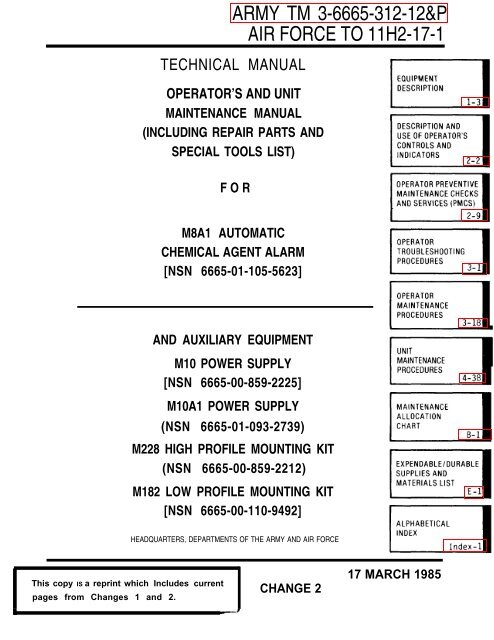
<strong>ARMY</strong> <strong>TM</strong> 3-<strong>6665</strong>-<strong>312</strong>-12&P<br />
<strong>AIR</strong> <strong>FORCE</strong> <strong>TO</strong> <strong>11H2</strong>-<strong>17</strong>-1<br />
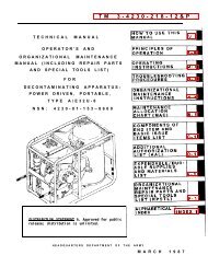
TECHNICAL MANUAL<br />
OPERA<strong>TO</strong>R’S AND UNIT<br />
MAINTENANCE MANUAL<br />
(INCLUDING REP<strong>AIR</strong> PARTS AND<br />
SPECIAL <strong>TO</strong>OLS LIST)<br />
FOR<br />
M8A1 AU<strong>TO</strong>MATIC<br />
CHEMICAL AGENT ALARM<br />
[NSN <strong>6665</strong>-01-105-5623]<br />
AND AUXILIARY EQUIPMENT<br />
M10 POWER SUPPLY<br />
[NSN <strong>6665</strong>-00-859-2225]<br />
M10A1 POWER SUPPLY<br />
(NSN <strong>6665</strong>-01-093-2739)<br />
M228 HIGH PROFILE MOUNTING KIT<br />
(NSN <strong>6665</strong>-00-859-2212)<br />
M182 LOW PROFILE MOUNTING KIT<br />
[NSN <strong>6665</strong>-00-110-9492]<br />
HEADQUARTERS, DEPAR<strong>TM</strong>ENTS OF THE <strong>ARMY</strong> AND <strong>AIR</strong> <strong>FORCE</strong><br />
This copy IS a reprint which Includes current<br />
pages from Changes 1 and 2.<br />
CHANGE 2<br />
<strong>17</strong> MARCH 1985
<strong>TM</strong> 3-<strong>6665</strong>-<strong>312</strong>-12&P<br />
<strong>AIR</strong> <strong>FORCE</strong> <strong>TO</strong> <strong>11H2</strong>-<strong>17</strong>-1<br />
C3<br />
CHANGE<br />
NO. 3<br />
HEADQUARTERS<br />
DEPAR<strong>TM</strong>ENT OF THE <strong>ARMY</strong><br />
WASHING<strong>TO</strong>N, D. C., 15 JULY 1991<br />
OPERA<strong>TO</strong>R AND ORGANIZATIONAL<br />
MAINTENANCE MANUAL<br />
(INCLUDING REP<strong>AIR</strong> PARTS AND SPECIAL <strong>TO</strong>OLS LIST)<br />
FOR<br />
M8A1 AU<strong>TO</strong>MATIC CHEMICAL AGENT ALARM<br />
<strong>TM</strong> 3-<strong>6665</strong>-<strong>312</strong>-12&P, March 1985 and Changes 1 and 2 are changed as follows:<br />
1. The purpose of this change is to update information and include Air Force references.<br />
2. Delete entire warnings on back of cover with pen and ink.<br />
3. New or changed material is indicated by a vertical bar in the margin of the page. Added<br />
illustrations are indicated by a vertical bar adjacent to the illustration identification number. Illustration<br />
changes are indicated by a miniature pointing hand.<br />
4. Remove old pages and insert new pages as indicated below.<br />
Remove Pages<br />
b<br />
i thru 1-0<br />
1-1 thru 1-6<br />
1-9 thru 1-12<br />
2-3 thru 2-6<br />
2-11 and 2-12<br />
2-<strong>17</strong> thru 2-22<br />
2-25 and 2-26<br />
2-29 and 2-30<br />
2-51 and 2-52<br />
2-65 and 2-66<br />
2-69 thru 2-86<br />
2-89 and 2-90<br />
2-113 and 2-114<br />
3-13 and 3-14<br />
4-33 and 4-34<br />
4-43 and 4-44<br />
4-58.1/(4-58.2blank)<br />
Insert Pages<br />
a and b<br />
i thru 1-0<br />
1-1 thru 1-6<br />
1-9 thru 1-12<br />
2-3 thru 2-6<br />
2-11 and 2-12<br />
2-<strong>17</strong> thru 2-22<br />
2-25 and 2-26<br />
2-29 and 2-30<br />
2-51 and 2-52<br />
2-65 and 2-66<br />
2-69 thru 2-86<br />
2-89 and 2-90<br />
2-113 and 2-114<br />
3-13 and 3-14<br />
4-33 and 4-34<br />
4-43 and 4-44<br />
4-58.1 and 4-58.2
<strong>ARMY</strong> <strong>TM</strong> 3-<strong>6665</strong>-<strong>312</strong>-12&P<br />
<strong>AIR</strong> <strong>FORCE</strong> <strong>TO</strong> <strong>11H2</strong>-<strong>17</strong>-1<br />
C3<br />
Remove Pages<br />
4-65 and 4-66<br />
4-79 and 4-80<br />
4-1<strong>17</strong> thru 4-119/(4-120 blank)<br />
A-1 and A-2<br />
B-1 thru B-9/(B-10 blank)<br />
C-1 thru C-4<br />
D-1 and D-2<br />
E-1 thru E-3/(E-4 blank)<br />
F-1 thru F-52<br />
G-1 and G-2<br />
H-1 and H-2<br />
Insert Pages<br />
4-65 and 4-66<br />
4-79 and 4-80<br />
4-1<strong>17</strong> thru 4-120<br />
A-1 and A-2<br />
B-1 thru B-8<br />
C-1 thru C-3/(C-4blank)<br />
D-1 and D-2<br />
E-1 and E-2<br />
F-1 thru F-I-7/(F-I-8 blank)<br />
G-1 and G-2<br />
H-1 and H-2<br />
5. File this change sheet in front of pubhcation for reference purposes.<br />
By order of the Secretaries of the Army and Air Force:<br />
GORDON R. SULLIVAN<br />
General, United States Army<br />
Chief of Staff<br />
Official:<br />
PATRICIA P. HICKERSON<br />
Colonel, United States Army<br />
The Adjutant General<br />
MERRILL A. McPEAK<br />
General United States Air Force<br />
Chief of Staff<br />
Official:<br />
CHARLES C. McDONALD<br />
General United States Air Force<br />
Commander Air Force Logistics Command<br />
Distribution:<br />
To redistributed in accordance with DA Form 12-28, Block 195, Maintenance Requirements for<br />
<strong>TM</strong> 3-<strong>6665</strong>-<strong>312</strong>-12&P.
<strong>ARMY</strong> <strong>TM</strong> 3-<strong>6665</strong>-<strong>312</strong>-12&P<br />
<strong>AIR</strong> <strong>FORCE</strong> <strong>TO</strong> <strong>11H2</strong>-<strong>17</strong>-1<br />
C2<br />
CHANGE<br />
NO.2<br />
HEADQUARTERS<br />
DEPAR<strong>TM</strong>ENTS OF THE <strong>ARMY</strong> AND <strong>AIR</strong> <strong>FORCE</strong><br />
Washington, DC., 13 March 1988<br />
OPERA<strong>TO</strong>R AND UNIT MAINTENANCE MANUAL<br />
(Including Repair Parts and Special Tools List)<br />
FOR<br />
M8A1 AU<strong>TO</strong>MATIC CHEMICAL AGENT ALARM<br />
(NSN <strong>6665</strong>-01-105-5623)<br />
AND AUXILIARY EQUIPMENT<br />
<strong>TM</strong> 3-<strong>6665</strong>-<strong>312</strong>-12&P, dated <strong>17</strong> March 1985, and Change 1 are changed as follows:<br />
1. New or changed material and added illustrations are indicated by a vertical bar in the margin of the page, RPSTL listing<br />
changes are indicated by an asterisk to the left of the Item Number column adjacent to the line item.<br />
2. Illustration changes are indicated by a miniature pointing hand.<br />
3. Remove old pages and insert new pages as indicated below:<br />
Remove Pages<br />
Insert Pages<br />
i and ii<br />
1-1 and 1-2<br />
1-9 thru 1-12<br />
2-1 and 2-2<br />
2-9 and 2-10<br />
2-15 and 2-16<br />
2-19 and 2-20<br />
2-25 thru 2-28<br />
2-31 thru 2-36<br />
2-57 thru 2-72<br />
2-75 thru 2-82<br />
2-85 and 2-86<br />
None<br />
2-87 thru 2-102<br />
2-1<strong>17</strong> and 2-118<br />
3-1 and 3-2<br />
3-5 thru 3-18<br />
4-1 and 4-2<br />
4-15 thru 4-26<br />
4-29 thru 4-32<br />
4-35 thru 4-38<br />
4-43 and 4-44<br />
None<br />
i and ii<br />
1-1 and 1-2<br />
1-9 thru 1-12<br />
2-1 and 2-2<br />
2-9 and 2-10<br />
2-15 and 2-16<br />
2-19 and 2-20<br />
2-25 thru 2-28<br />
2-31 thru 2-36<br />
2-57 thru 2-72<br />
2-75 thru 2-82<br />
2-85 and 2-86<br />
2-86.1 and 2-86.2<br />
2-87 thru 2-102<br />
2-1<strong>17</strong> and 2-118<br />
3-1 and 3-2<br />
3-5 thru 3-18<br />
4-1 and 4-2<br />
4-15 thru 4-26<br />
4-29 thru 4-32<br />
4-35 thru 4-38<br />
4-43 and 4-44<br />
4-58,1 /(4-58,2 blank)
<strong>ARMY</strong> <strong>TM</strong> 3-<strong>6665</strong>-<strong>312</strong>-12&P<br />
<strong>AIR</strong> <strong>FORCE</strong> <strong>TO</strong> <strong>11H2</strong>-<strong>17</strong>-1<br />
C2<br />
Remove Pages<br />
Insert Pages<br />
4-1<strong>17</strong> thru 4-1 19/(4-120 blank) 4-1<strong>17</strong> thru 4-119/(4-120 blank)<br />
A-1 and A-2 A-1 and A-2<br />
B-3 thru B-9/(B-10 blank) B-3 thru B-9/(B-10 blank)<br />
E-1 thru E-3/(E-4 blank) E-1 thru E-3/(E-4 blank)<br />
F-1 thru F-6 F-1 thru F-6<br />
F-9 and F-10 F-9 and F-10<br />
F-15 thru F-18/(F-19 blank) F-15 thru F-18/(F-19 blank)<br />
F-35 and F-36 F-35 and F-36<br />
F-43 and F-44 F-43 and F-44<br />
F-47 thru F-52 F-47 thru F-52<br />
G-land G-2 G-land G-2<br />
lndex-5 thru lndex-8<br />
Index-5 thrulndex-8<br />
Sample DA Form 2028-2 and blank Sample DA Form 2028-2 and blank<br />
DA Form 2028-2 and Envelope<br />
DA Form 2028-2 and Envelope<br />
Cover and a<br />
Cover and a<br />
4.<br />
File this change sheet and all previous change sheets in back of the publication for reference purposes.<br />
By Order of the Secretaries of the Army and Air Force:<br />
CARL E. VUONO<br />
General United States Army<br />
Chief of Staff<br />
Official:<br />
R. L. DILWORTH<br />
Brigadier General, United States Army<br />
The Adjutant General<br />
LARRY D. WELCH, General, USAF<br />
Chief of Staff<br />
EARL T. O’LOUGHLIN, General, USAF<br />
Commander, Air Force Logistics Command<br />
Distribution:<br />
To be distributed in accordance with DA Form 12-28, Blocks 193 and 194, Operator and Unit Maintenance (Including Repair<br />
Parts and Special Tools List), for Detection and Warning Systems, Alarms.
<strong>TM</strong> 3-<strong>6665</strong>-<strong>312</strong>-12&P<br />
C1<br />
CHANGE<br />
NO. 1<br />
HEADQUARTERS<br />
DEPAR<strong>TM</strong>ENT OF THE <strong>ARMY</strong><br />
WASHING<strong>TO</strong>N, D.C. , 10 APRIL 1986<br />
OPERA<strong>TO</strong>R AND ORGANIZATIONAL<br />
MAINTENANCE MANUAL<br />
(REP<strong>AIR</strong> PARTS AND SPECIAL <strong>TO</strong>OLS LIST)<br />
M8A1 AU<strong>TO</strong>MATIC<br />
CHEMICAL AGENT ALARM<br />
(NSN <strong>6665</strong>-01-105-5623)<br />
<strong>TM</strong> 3-<strong>6665</strong>-<strong>312</strong>-12&P, March 1985 is changed as follows:<br />
1. Remove old pages and insert new pages as indicated below.<br />
2. New or changed material is indicated by a vertical change bar in the margin<br />
of the page.<br />
3. Added or revised illustrations are indicated by a vertical bar adjacent to<br />
the illustration identification number.<br />
Remove Pages<br />
iii and 1-0<br />
1-9 through 1-14 (blank)<br />
2-1 and 2-2<br />
2-59 through 2-66<br />
3-<strong>17</strong> and 3-18<br />
4-1 and 4-2<br />
4-23 through 4-26<br />
4-31 and 4-32<br />
4-37 through 4-40<br />
4-43 and 4-44<br />
None<br />
4-61 and 4-62<br />
4-99 and 4-100<br />
4-119 and 4-120 (blank)<br />
A-1 and A-2<br />
B-7 and B-8<br />
C-3 and C-4<br />
E-3 and E-4 (blank)<br />
F-13 and F-14<br />
Insert Pages<br />
iii and 1-0<br />
1-9 through 1-14<br />
2-1 and 2-2<br />
2-59 through 2-66<br />
3-<strong>17</strong> and 3-18<br />
4-1 and 4-2<br />
4-23 through 4-26<br />
4-31 and 4-32<br />
4-37 through 4-40<br />
4-43 and 4-44<br />
4-49.1 and 49.2<br />
4-61 and 4-62<br />
4-99 and 4-100<br />
4-19 and 4-120 (blank)<br />
A-1 and A-2<br />
B-7 and B-8<br />
C-3 and C-4<br />
E-3 and E-4 (blank)<br />
F-13 and F-14<br />
File this change sheet in front of the publication for reference purposes.
By Order of the Secretary of the Army:<br />
JOHN A. WICKHAM, JR.<br />
General, United States Army<br />
Chief of Staff<br />
Official:<br />
R. L. DILWORTH<br />
Brigadier General, United States Army<br />
The Adjutant General<br />
Distribution:<br />
To be distributed in accordance with DA Form 12-28, Blocks 193 and 194,<br />
Operator and Organizational Maintenance (Including Repair Parts and Special<br />
Tools List), for Detection and Warning Systems and Alarms.
<strong>ARMY</strong> <strong>TM</strong> 3-<strong>6665</strong>-<strong>312</strong>-12&P<br />
<strong>AIR</strong> <strong>FORCE</strong> <strong>TO</strong> <strong>11H2</strong>-<strong>17</strong>-1<br />
WARNING<br />
RADIATION HAZARD<br />
AMERICIUM (AM241)<br />
The cell module of the M43A1 Detector contains a radioactive source: Americium-241.<br />
The cell module is potentially dangerous if broken.<br />
1. Do not attempt to remove the cell or pump modules.<br />
2. Follow safety procedures for storage, shipment, and disposal in accordance with this manual,<br />
local regulations, and AR 385-11, Air Force personnel use Technical Orders <strong>TO</strong> 00-110N-2 and<br />
<strong>TO</strong> 00-110N-3.<br />
3. If a cell or pump module is damaged, notify your NBC NCO. The NBC NCO must then notify the<br />
Nuclear-Biological-Chemical Officer and Radiation Protection Officer.<br />
4. Wrap the M43A1 Detector (with its damaged cell or pump module) in a plastic bag and ship in the<br />
original packing container, if available, to Intermediate Direct Support for evaluation. Wash<br />
immediately with nonabrasive soap and water if skin contact is made with any area thought to be<br />
contaminated.<br />
5. Do not operate an M43A1 Detector indoors without an outlet filter. Never operate an M43A1<br />
Detector inside a moving vehicle with or without an outlet filter.<br />
6. Do not dispose of a used outlet filter except under the supervision of the NBC NCO or Officer or<br />
local RPO, You must wear disposable gloves.<br />
Change 3<br />
a
<strong>ARMY</strong> <strong>TM</strong> 3-<strong>6665</strong>-<strong>312</strong>-12&P<br />
<strong>AIR</strong> <strong>FORCE</strong> <strong>TO</strong> <strong>11H2</strong>-<strong>17</strong>-1<br />
WARNING<br />
HIGH VOLTAGE<br />
is used in the operation of this equipment<br />
DEATH ON CONTACT<br />
may result if personnel fail to observe safety precautions when performing maintenance procedures on<br />
the M43A1 Detector.<br />
● DISCONNECT POWER SUPPLIES BEFORE PERFORMING MAINTENANCE <strong>TO</strong> PREVENT<br />
DEATH OR POSSIBLE SERIOUS INJURY.<br />
● DISCONNECT THE M10 OR M10A1 POWER SUPPLY FROM THE AC POWER OUTLET<br />
BEFORE REMOVING THE FUSES <strong>TO</strong> PREVENT POSSIBLE DEATH OR SERIOUS INJURY<br />
<strong>TO</strong> PERSONNEL.<br />
For Artificial Respiration, refer to FM 21-11.<br />
b Change 3
<strong>ARMY</strong> <strong>TM</strong> 3-<strong>6665</strong>-<strong>312</strong>-12&P<br />
<strong>AIR</strong> <strong>FORCE</strong> <strong>TO</strong> <strong>11H2</strong>-<strong>17</strong>-1<br />
Technical Manual<br />
No. 3-<strong>6665</strong>-<strong>312</strong>-12&P<br />
HEADQUARTERS<br />
DEPAR<strong>TM</strong>ENTS OF THE <strong>ARMY</strong> AND <strong>AIR</strong> <strong>FORCE</strong><br />
Washington. D.C.<br />
<strong>17</strong> March 1985<br />
OPERA<strong>TO</strong>R AND UNIT MAINTENANCE MANUAL<br />
(Including Repair Parts and Special Tools List)<br />
FOR<br />
M8A1 AU<strong>TO</strong>MATIC CHEMICAL AGENT ALARM<br />
(NSN <strong>6665</strong>-01-105-5623)<br />
AND AUXILIARY EQUIPMENT<br />
REPORTING ERRORS AND RECOMMENDING IMPROVEMENTS<br />
You can help improve this manual. If you find any mistakes or if you know of a way to<br />
improve the procedures, please let us know, Mail your letter, DA Form 2028<br />
(Recommended Changes to Publications and Blank Forms), or DA Form 2028-2 located in<br />
the back of this manual direct to Commander, U.S. Army Armament, Munitions, and<br />
Chemical Command, Attn: AMSMC-MAR-T (A), Aberdeen Proving Ground, MD 21010-5423.<br />
A reply will be furnished to you.<br />
CHAPTER 1<br />
Section I<br />
Section II<br />
Section Ill<br />
Page<br />
INTRODUCTION . . . . . . . . . . . . . . . . . . . . . . . . . . . . . . . . . . . . . . . . . . . . .. . . . . . . . . . . . . . . . .. 1-1<br />
General Information . . . . . . . . . . . . . . . . . . . . . . . . . . . . . . . . . . . . . . . . . . . . . . . . . . . . . . . . . . 1-1<br />
IEquipment Description. . . . . . . . . . . . . . . . . . . . . . . . . . . . . . . . . . . . . . . . . . . . . . . . . . . . . . . . . . . . . . . . . . . . . . . . . . . . . . . . . . . . . . . . . . . . . 1-3<br />
Technical Principles of Operation . . . . . . . . . . . . . . . . . . . . . . . . . . . . . . . . . . . . . . . . . . . . . . . . . . . . . . . . . . . . . . . . . . . . . . . . 1-13<br />
CHAPTER 2<br />
Section I<br />
Section II<br />
Section Ill<br />
Section IV<br />
OPERATING INSTRUCTIONS . . . . . . . . . . . . . . . . . . . . . . . . . . . . . . . . . . . . . . . . . . . . . . . . . . . . . . . . . . . . . . . . . . . . . . . . . . . . . . . . . . . . . . 2-1<br />
I Description and Use of Operationsl<br />
Controls and Indicators . . . . . . . . . . . . . . . . . . . . . . . . . . . . . . . . . . . . . . . . . . . . . . . . . . . . . . . . . . . . . . . . . . . . 2-2<br />
Operator Preventive Maintenance<br />
IChecks and Services (PMCS) . . . . . . . . . . . . . . . . . . . . . . . . . . . . . . . . . . . . . . . . . . . . . . . . . . . . . . . . . . . . . . . . . . . . 2-9<br />
Operation Under Usual Conditions . . . . . . . . . . . . . . . . . . . . . . . . . . . . . . . . . . . . . . . . . . . . . . . . . . . . . . . . . . . . . . 2-37<br />
Operation Under Unusual Conditions . . . . . . . . . . . . . . . . . . . . . . . . . . . . . . . . . . . . . . . . . . . . . . . . . . . . . . . . . 2-109<br />
CHAPTER 3<br />
Section I<br />
Section II<br />
Section Ill<br />
OPERA<strong>TO</strong>R MAINTENANCE . . . . . . . . . . . . . . . . . . . . . . . . . . . . . . . . . . . . . . . . . . . . . . . . . . . . . . . . . . . . . . . . . . . . . . . . . . . . . . . . 3-1<br />
Lubrication Instructions . . . . . . . . . . . . . . . . . . . . . . . . . . . . . . . . . . . . . . . . . . . . . . . . . . . . . . . . . 3-1<br />
Operator Troubleshooting Procedures ,. . . . . . . . . . . . . . . . . . . . . . . . . . . . . . . . . . . . . . . . . . . . . . . . . . . 3-1<br />
Operator Maintenance Procedures . . . . . . . . . . . . . . . . . . . . . . . . . . . . . . . . . . . . . . . . . . . . 3-18<br />
Change 3 i
<strong>ARMY</strong> <strong>TM</strong> 3-<strong>6665</strong>-<strong>312</strong>-12&P<br />
<strong>AIR</strong> <strong>FORCE</strong> <strong>TO</strong> <strong>11H2</strong>-<strong>17</strong>-1<br />
CHAPTER 4<br />
Section I<br />
Section II<br />
Section Ill<br />
Section IV<br />
Section V<br />
APPENDIX A<br />
APPENDIX B<br />
Section I<br />
Section II<br />
Section Ill<br />
Section IV<br />
APPENDIX C<br />
Section I<br />
Section II<br />
Section Ill<br />
APPENDIX D<br />
Section I<br />
Section II<br />
APPENDIX E<br />
Section I<br />
Section II<br />
APPENDIX F<br />
Section I<br />
Section II<br />
Group 00<br />
Page<br />
UNIT MAINTENANCE lNSTRUCTIONS . . . . . . . . . . . . . . . . . . . . . . . . . . . . . . . . . . . . . . 4-1<br />
Repair Parts, Special Tools, <strong>TM</strong>DE<br />
and Support Equipment . . . . . . . . . . . . . . . . . . . . . . . . . . . . . . . . . . . . . 4-3<br />
Service Upon Receipt . . . . . . . . . . . . . . . . . . . . . . . . . . . . . . . . . . . . . . . . . . . . . . . . . . . . 4-3<br />
Unit Troubleshooting Procedures . . . . . . . . . . . . . . . . . . . . . . . . . . . . . . . . . . . . . 4-15<br />
lUnit Maintenance Procedures . . . . . . . . . . . . . . . . . . . . . . . . . . . . . . . . . . . . 4-38<br />
Preparation for Storage or Shipment . . . . . . . . . . . . . . . . . . . . . . . . . . . . . . . . . . . 4-118<br />
REFERENCES . . . . . . . . . . . . . . . . . . . . . . . . . . . . . . . . . . . . . . . . . . . . . . . . . . A-1<br />
MAINTENANCE ALLOCATION CHART . . . . . . . . . . . . . . . . . . . . . . . . B-1<br />
Introduction . . . . . . . . . . . . . . . . . . . . . . . . . . . . . . . . . . . . . . . . . . . . . . . . . . . . B-2<br />
Maintenance Allocation Chart. . . . . . . . . . . . . . . . . . . . . . . . . . . . . . . . . . . . . . . B-4<br />
Tool and Test Equipment Requirements . . . . . . . . . . . . . . . . . . . . . . . . . . . B-7<br />
Remarks . . . . . . . . . . . . . . . . . . . . . . . . . . . . . . . . . . . . . . . . . . . . . . . . . . . B-8<br />
COMPONENTS OF END ITEM AND BASIC<br />
ISSUE ITEMS. . . . . . . . . . . . . . . . . . . . . . . . . . . . . . . . . . . . . .. . . . C-1<br />
Introduction . . . . . . . . . . . . . . . . . . . . . . . . . . . . . . . . . . . . . . . .. . . . . . . . .C-1<br />
Components of End Items . . . . . . . . . . . . . . . . . . . . . . . . . . . . . . . . . . . . . C-2<br />
Basic Issue Items . . . . . . . . . . . . . . . . . . . . . . . . . . . . . . . . . . . . . . . C-3<br />
ADDITIONAL AUTHORIZATION LlST . . . . . . . . . . . . . . . . . . .. . . . . . . . . . . . . . . . . . . D-1<br />
Introduction . . . . . . . . . . . . . . . . . . . . . . . . . . . . . . . . .. . . . . . . . . D-1<br />
Additional Authorization List . . . . . . . . . . . . . . . . . . . . . D-2<br />
IEXPENDABLVDURABLE suppLIEs AND I<br />
MATERIALS LIST . . . . . . . . . . . . . . . . . . . . . . . . . . . . . . . . E-1<br />
Introduction . . . . . . . . . . . . . . . . . . . . . . . . . . . . . . . . . . . . . . . . . . . . . . E-1<br />
Expendable/Durable Supplies and Materials List. . . . . . . . . . . . . . . . . . . . . . . . . . E-2<br />
Page<br />
REP<strong>AIR</strong> PARTS AND SPECIAL<br />
<strong>TO</strong>OLS LIST (RPSTL) . . . . . . . . . . . . . . . . . . . .F-1<br />
Introduction . . . . . . . . . . . . . . . . . . . . . . . . . . . . . . . . . . . . . . . F-1<br />
Repair Parts List. . . . . . . . . . . . . . . . . . . . . . . . . . . . . . . . . . . F-1-1<br />
M8A1 Automatic Chemical Agent Alarm . . . . . . . . . . . . . . . . F-1-1 1<br />
Illus/<br />
Figure<br />
ii Change 3
<strong>ARMY</strong> <strong>TM</strong> 3-<strong>6665</strong>-<strong>312</strong>-12&P<br />
<strong>AIR</strong> <strong>FORCE</strong> <strong>TO</strong> <strong>11H2</strong>-<strong>17</strong>-1<br />
Group 01<br />
Group 02<br />
Group 03<br />
Group 04<br />
Group 05<br />
Group 06<br />
Group 99<br />
Section Ill<br />
Section IV<br />
Page<br />
M43A1 Detector Unit. . . . . . . . . . . . . . . . . . . . . . . . . . . . . . . . . F-2-1<br />
0101 Top Case. . . . . . . . . . . . . . . . . . . . . . . . . . . . . . . . . . . . . . . F-3-1<br />
01010 Air Protective Cap . . . . . . . . . . . . . . . . . . . . . . . . . . . . . . . . F-4-1<br />
010102 Flow Rate Meter . . . . . . . . . . . . . . . . . . . . . . . . . F-5-1<br />
010103 Detector Unit Case . . . . . . . . . . . . . . . . . . . . F-6-1<br />
M42 Alarm Unit. . . . . . . . . . . . . . . . . . . . . . . . . . . . . . . . . . . . . . . . F-7-1<br />
0201 Panel Assembly . . . . . . . . . . . . . . . . . . . . . . . . . . . . . F-8-1<br />
M10A1 Power Supply . . . . . . . . . . . . . . . . . . . . . . . . . . . F-9-1<br />
0301 Cable Assembly . . . . . . . . . . . . . . . . . . . . . . . . . F-10-1<br />
0302 Power Supply Assembly . . . . . . . . . . . . . . . . . . . . . . . F-11-1<br />
M10 Power Supply. . . . . . . . . . . . . . . . . . . . . . . . . . . . . . . F-12-1<br />
0401 Panel Subassembly . . . . . . . . . . . . . . . . . . . . . . . . F-13-1<br />
040101 Cable Assembly . . . . . . . . . . . . . . . . . . . . .F-14-1<br />
M228 High Profile Mounting Kit . . . . . . . . . . . . . . . . . . . . . F-15-1<br />
0501 High Profile Mount. . . . . . . . . . . . . . . . . . . . . . . . F-16-1<br />
0502 Base . . . . . . . . . . . . . . . . . . . . F-<strong>17</strong>-1<br />
M182 Low Profile Mounting Kit .. . . . . . . . . . . . . . . . . . . . . F-18-1<br />
0601 Low Profile Mount . . . . . . . . . . . . . . . . . F-19-1<br />
0602 Base . . . . . . . . . . . . . . .. . . . . . . . . . . . . . . . . F-20-1<br />
Bulk Materials. . . . . . . . . . . . . . . . . . . . . . . . . . . . BULK-1<br />
Special Tools List (Not Applicable)<br />
National Stock Number and Part Number Index . . . . . . . . . . . . . . . . . F-1-1<br />
Illus/<br />
Figure<br />
2<br />
3<br />
4<br />
5<br />
6<br />
7<br />
8<br />
9<br />
10<br />
11<br />
12<br />
13<br />
14<br />
15<br />
16<br />
<strong>17</strong><br />
18<br />
19<br />
20<br />
APPENDIX G<br />
APPENDIX H<br />
ILLUSTRATED LIST OF MANUFACTURED lTEMS . . . . . . . . . . . . . . . . . . . . . . . . G-1<br />
NUCLEAR REGULA<strong>TO</strong>RY COMMISSION<br />
REQUIREMENTS . . . . . . . . . . . . . . . . . . . . . . . . . . . . . . . . . . . . . . . . . . . . . . . . . H-1<br />
Page<br />
ALPHABETICAL INDEX<br />
. . . . . . . . . . . . . . . . . . . . . . . . . . . . . . . . . . . . . . . . . . . . . . Index-1<br />
Change 3 iii
<strong>ARMY</strong> <strong>TM</strong> 3-<strong>6665</strong>-<strong>312</strong>-12&P<br />
<strong>AIR</strong> <strong>FORCE</strong> <strong>TO</strong> <strong>11H2</strong>-<strong>17</strong>-1<br />
M43A1 DETEC<strong>TO</strong>R<br />
M42 ALARM<br />
M228 MOUNTING KIT<br />
MOUNTING BRACKET<br />
M182 MOUNTING KIT<br />
M1OA1 POWER SUPPLY<br />
M10 POWER SUPPLY<br />
l PART OF M182 AND M228 MOUNTING KITS<br />
1-0 Change 3
<strong>ARMY</strong><strong>TM</strong>3-<strong>6665</strong>-<strong>312</strong>-12&P<br />
<strong>AIR</strong> <strong>FORCE</strong> <strong>TO</strong> <strong>11H2</strong>-<strong>17</strong>-1<br />
CHAPTER 1<br />
INTRODUCTION<br />
PARA<br />
1-1<br />
1-2<br />
1-3<br />
1-4<br />
1-5<br />
1-6<br />
1-7<br />
1-8<br />
1-9<br />
1-10<br />
1-11<br />
1-12<br />
1-13<br />
PAGE<br />
Scope . . . . . . . . . . . . . . . . . . . . . . . . . . . . . . . . . . . . . . . . . . . . . . . . . . . . . . . . . . . . . . . . . . . . . . . . . . . . 1-1<br />
Maintenance Forms and Records and Reports . . . . . . . . . . . . . . . . . . . . . . . . . . . . . . . . . . . . . . 1-2<br />
Reporting Equipment Improvement Recommendations (EIR’s). . . . . . . . . . . . . . . . . . . . . . . 1-2<br />
Nomenclature Cross-Reference List . . . . . . . . . . . . . . . . . . . . . . . . . . . . . . . . . . . . . . . . . . . . . . . 1-2<br />
Destruction of Army Materiel to Prevent Enemy Use . . . . . . . . . . . . . . . . . . . . . . . . . . . . . . . . 1-3<br />
Preparation for Storage or Shipment . . . . . . . . . . . . . . . . . . . . . . . . . . . . . . . . . . . . . . . . . . . . . . 1-3<br />
Equipment Characteristics, Capabilities, and Features . . . . . . . . . . . . . . . . . . . . . . . . . . . . . 1-3<br />
Location and Description of Major Components and Auxiliary Equipment . . . . . . . . . . . . . . . . . . 1-4<br />
Equipment Data . . . . . . . . . . . . . . . . . . . . . . . . . . . . . . . . . . . . . . . . . . . . . . . . . . . . . . . . . . . . . . . . . . 1-9<br />
Equipment Configurations . . . . . . . . . . . . . . . . . . . . . . . . . . . . . . . . . . . . . . . . . . . . . . . . . . . . . . . . 1-11<br />
Safety, Care, and Handling . . . . . . . . . . . . . . . . . . . . . . . . . . . . . . . . . . . . . . . . . . . . . . . . . . . . . . . . 1-11<br />
Purpose and Equipment Components . . . . . . . . . . . . . . . . . . . . . . . . . . . . . . . . . . . . . . . . . . . . . . 1-13<br />
Detector Airflow Sampling Operation . . . . . . . . . . . . . . . . . . . . . . . . . . . . . . . . . . . . . . . . . . . . . . 1-13<br />
CHAPTER OVERVIEW<br />
This chapter introduces you to general information, equipment description, and technical principles<br />
of operation of the M8Al Alarm and its auxiliary equipment.<br />
I 1-1 SCOPE. ]<br />
Section 1. GENERAL INFORMATION<br />
a. Type of Manual Operator and Uni tMaintenance, including Repair Parts and Special Tools List<br />
b. Equipment Name and Model Number.<br />
(1)<br />
M8A1 Automatic Chemical Agent Alarm consisting of:<br />
M43A1 Chemical Agent Automatic Alarm Detector Unit<br />
M42 Chemical A[arm lJnit<br />
(2)<br />
(3)<br />
(4)<br />
(5)<br />
M10A1 Power Supply<br />
M10 Power Supply<br />
M182 Low Profile Mounting Kit<br />
M228 High Profile Mounting Kit<br />
Change 2 1-1
<strong>ARMY</strong> <strong>TM</strong> 3-<strong>6665</strong>-<strong>312</strong>-12&P<br />
<strong>AIR</strong> <strong>FORCE</strong> <strong>TO</strong> <strong>11H2</strong>-<strong>17</strong>-1<br />
I 1-1 SCOPE (CONT).<br />
c. Purpose of Equipment. Provides a method of automatically detecting chemical nerve agents in<br />
the air and then gives an alarm. Can be vehicle mounted, backpacked, or ground emplaced. The M10<br />
or M10A1 power supplies can be used to power the M8A1 Alarm when 115 or 220 vac is available.<br />
The alarm system will detect nerve agents GA, GB, GD, and VX only.<br />
I 1-2 MAINTENANCE FORMS AND RECORDS AND REPORTS. ]<br />
a. Maintenance. Department of the Army forms and procedures used for equipment maintenance<br />
will be those prescribed by DA PAM 738-750, The Army Maintenance Management Systems (TAMMS)<br />
as contained in the Maintenance Management UPDATE.<br />
b. Report of Packaging and Handling Deficiencies. Fill out and forward SF 364 (Report of<br />
Discrepancy) as prescribed in AR 735-11-2.<br />
c. Discrepancy in Shipment Report. Fill out and forward Discrepancy in Shipment Report (SF 361)<br />
as prescribed in AR 55-38.<br />
d. Radiological Accident Reports, RCS DD-SD (AR) 1168. Fill out and forward as prescribed in<br />
AR 385-40. Air Force personnel use AFR 161-16 and AFR 127-4.<br />
1-3 REPORTING EQUIPMENT IMPROVEMENT RECOMMENDATIONS (EIRs).<br />
If your M8A1 Alarm or auxiliary equipment needs improvement, let us know. Send us an EIR. You,<br />
the user, are the only one who can tell us what you don’t like about your equipment. Let us know why<br />
you don’t like the design or performance. Put it on an SF 368 (Quality Deficiency Report). Mail it to<br />
us at: Commander, U.S. Army Armaments, Munitions, and Chemical Command, ATTN: AMSMC-MAR-A(A),<br />
Aberdeen Proving Ground, MD 21010-5423. We’ll send you a reply.<br />
1-4 NOMENCLATURE CROSS REFERENCE LIST.<br />
Common Name<br />
adapter<br />
air filter plug<br />
BAT indicator<br />
BATTERY TEST & RESET PRESS button<br />
BIT PRESS button<br />
bottom case<br />
cell module<br />
detector meter<br />
electronics module<br />
Official Nomenclature<br />
air protective cap adapter<br />
protective dust plug<br />
indicating light<br />
battery reset test pushbutton<br />
bit pushbutton<br />
cover<br />
chemical agent detector cell<br />
arbitrary scale meter<br />
electronic module amplifier<br />
1-2 Change 3
<strong>ARMY</strong> <strong>TM</strong> 3-<strong>6665</strong>-<strong>312</strong>-12&P<br />
<strong>AIR</strong> <strong>FORCE</strong> <strong>TO</strong> <strong>11H2</strong>-<strong>17</strong>-1<br />
1-4 NOMENCLATURE CROSS REFERENCE LIST. I<br />
Common Name<br />
FLOWMETER<br />
fuseholder<br />
M8A1 Alarm<br />
M42 Alarm<br />
M43A1 Detector<br />
M10 power cable<br />
M10 DETEC<strong>TO</strong>R POWER cable<br />
M10 STANDBY BATTERY cable<br />
M10A1 power cable<br />
M182 Mounting Kit<br />
M228 Mounting Kit<br />
plug<br />
pump module<br />
rain shield<br />
RESET/SET button<br />
turnlock<br />
Official Nomenclature<br />
liquid sight indicator<br />
fuseholder extractor<br />
M8A1 Automatic Chemical Agent Alarm<br />
M42 Chemical Alarm Unit<br />
M43A1 Chemical Agent Automatic Alarm Detector Unit<br />
power cable assembly W1<br />
power cable assembly W2<br />
power cable assembly W3<br />
electrical power cable assembly<br />
M182 Low Profile Mounting Kit<br />
M228 High Profile Mounting Kit<br />
electrical connector plug<br />
vacuum pump unit<br />
air protective cap<br />
push button<br />
turnlock fastener assembly<br />
I 1-5 DESTRUCTION OF <strong>ARMY</strong> MATERIAL <strong>TO</strong> PREVENT ENEMY USE.<br />
Refer to <strong>TM</strong> 43-0002-31, Destruction of Chemical Weapons and Defense Equipment to Prevent Enemy<br />
Use, Section 3, for procedures to destroy the M8A1 Alarm and auxiliary equipment.<br />
1-6 PREPARATION FOR S<strong>TO</strong>RAGE OR SHIPMENT.<br />
Refer to Chapter 4, Section V, for special instructions concerning storage or shipment.<br />
Section Il. EQUIPMENT DESCRIPTION<br />
1-7 EQUIPMENT CHARACTERISTICS CAPABILITIES AND FEATURES.<br />
a. Characteristics<br />
(1) Operates in fixed, portable or vehicle mounted configurations.<br />
(2) All-weather operational.<br />
(3) Fully functional under dusty conditions.<br />
b. Capabilities and Features<br />
(1) Automatically senses nerve agents in the air and provides a warning.<br />
(2) Can be connected to a remote alarm unit<br />
(3) Operation from various electrical power sources.<br />
Change 3 1-3
<strong>TM</strong> 3-<strong>6665</strong>-<strong>312</strong>-12&P<br />
1-8 LOCATION AND DESCRIPTION OF MAJOR COMPONENTS AND AUXILIARY EQUIPMENT.<br />
a. M43A1 Detector<br />
Automatically detects nerve<br />
agents in the air. Will sound an<br />
alarm and send a signal to connected<br />
M42 Alarm.<br />
b. M42 Alarm<br />
Provides a warning light and horn<br />
at a remote location when M43A1<br />
Detector detects nerve agent.<br />
1-4
<strong>ARMY</strong> <strong>TM</strong> 3-<strong>6665</strong>-<strong>312</strong>-12&P<br />
<strong>AIR</strong> <strong>FORCE</strong> <strong>TO</strong> <strong>11H2</strong>-<strong>17</strong>-1<br />
1-8 LOCATION AND DESCRIPTION OF MAJOR COMPONENTS AND AUXILIARY EQUIPMENT.<br />
c. M10A1 POWER SUPPLY<br />
Provides dc power to the M43A1 Detector<br />
from an ac power source. Accepts 115 or<br />
220 vac, 50 to 400 Hz. Switches automatically<br />
to standby battery if output drops<br />
below 18 vdc. Attaches directly to bottom<br />
of M43A1 Detector.<br />
d. M10 Power Supply<br />
Provides dc power to the M43A1 Detector<br />
from an ac power source. Accepts 115 or<br />
220 vac, 50 to 400 Hz. Switches<br />
automatically to standby battery if output<br />
drops below 18 vdc.<br />
Change 3 1-5
<strong>TM</strong> 3-<strong>6665</strong>-<strong>312</strong>-12&P<br />
1-8 LOCATION AND DESCRIPTION OF MAJOR COMPONENTS AND AUXILIARY EQUIPMENT (CONT).<br />
e. BA35<strong>17</strong>/U Battery<br />
Provides 36 vdc power to M43A1 Detector.<br />
Attaches to bottom of detector or M10A1<br />
Power Supply. Not rechargeable.<br />
f.<br />
M228 Mounting Kit<br />
Provides mount for M43A1 Detector, with<br />
or without battery, for 1/4-ton utility<br />
trucks or 2-1/2-ton trucks. Vehicle must<br />
have an installation kit (<strong>TM</strong> 3-<strong>6665</strong>-274-<br />
20) before M228 Mounting Kit can be<br />
installed.<br />
1-6
<strong>TM</strong> 3-<strong>6665</strong>-<strong>312</strong>-12&P<br />
1-8 LOCATION AND DESCRIPTION OF MAJOR COMPONENTS AND AUXILIARY EQUIPMENT.<br />
g. M182 Mounting Kit<br />
Provides mount for M43A1 Detector, for<br />
fully-tracked armored personnel carriers<br />
and recovery vehicles. Vehicle must have<br />
an installation kit (<strong>TM</strong> 3-<strong>6665</strong>-274-20)<br />
before M182 Mounting Kit can be<br />
installed.<br />
h. M42 Alarm Unit Mounting Bracket<br />
Provides vehicle mounting for M42 Alarm.<br />
Comes with M228 and M182 Mounting<br />
Kits.<br />
1-7
<strong>TM</strong> 3-<strong>6665</strong>-<strong>312</strong>-12&P<br />
1-8 LOCATION AND DESCRIPTION OF MAJOR COMPONENTS AND AUXILIARY EQUIPMENT (CONT).<br />
i. Backpack<br />
Provides mount for M43A1 Detector and<br />
BA35<strong>17</strong>/U Battery on person’s back,<br />
consists of field pack frame, cargo<br />
support shelf, and webbing straps.<br />
j. M253 Winterization Kit<br />
Provides dc power to the detector when<br />
temperature ranges from 20°F to -40°F<br />
(-7°C to -40°C), Kit contains two BB501/U<br />
rechargeable batteries and one M168<br />
Cable. -<br />
1-8
<strong>ARMY</strong> <strong>TM</strong> 3-<strong>6665</strong>-<strong>312</strong>-121&P<br />
<strong>AIR</strong> <strong>FORCE</strong> <strong>TO</strong> <strong>11H2</strong>-<strong>17</strong>-1<br />
1-8 LOCATION AND DESCRIPTION OF MAJOR COMPONENTS AND AUXILIARY EQUIPMENT.<br />
k. M273 Maintenance Kit<br />
Contains 10 air filters and 10 test paddles,<br />
each wrapped in paper and foil.<br />
1. Probe Assembly<br />
Contains 5 probes, 5 rubber bands, and 5<br />
instruction cards, one of each packed separately<br />
in a heat sealed plastic bag. Enables<br />
the M43A1 Detector to monitor equipment,<br />
vehicles and personnel for vapor contamination.<br />
1-9 EQUIPMENT DATA.<br />
Table 1-1 Weights and Dimensions<br />
EQUIPMENT WEIGHT LENGTH WIDTH HEIGHT<br />
M43A1 Detector 7 lb 7 in. 7.75 in. 10.75 in.<br />
3.2 kg <strong>17</strong>7.8 mm 196.9 mm 273.0 mm<br />
M42 Alarm Unit 4 lb 8 in. 6 in. 2.25 in.<br />
1.8 kg 203.2 mm 152.4 mm 57.2 mm<br />
M10A1 Power Supply 6.5 lb 7.5 in. 6.5 in. 3.2 in.<br />
2.9 kg 190.5 mm 165.1 mm 81.3 mm<br />
M10 Power Supply 18 lb 12 in. 6 in. 7 in.<br />
8.16 kg 304.8 mm 152.4 mm <strong>17</strong>7.8 mm<br />
Change 3 1-9
<strong>ARMY</strong> <strong>TM</strong> 3-<strong>6665</strong>-<strong>312</strong>-12&P<br />
<strong>AIR</strong> <strong>FORCE</strong> <strong>TO</strong> <strong>11H2</strong>-<strong>17</strong>-1<br />
1-9 EQUIPMENT DATA (CONT).<br />
Table 1-1 Weights and Dimensions<br />
EQUIPMENT WEIGHT LENGTH WIDTH HEIGHT<br />
BA35<strong>17</strong>/U Battery 7.5 lb 6.3 in. 7.7 in. 5 in.<br />
3.4 kg 160 mm 195.6 mm 130 mm<br />
M228 Mounting Kit<br />
M182 Mounting Kit<br />
I<br />
I<br />
16 lb<br />
9 in.<br />
10 in.<br />
14 in.<br />
7.3 kg<br />
I 228.6 mm I 254.0 mm I 355.6 mm<br />
15 lb<br />
9 in. 10 in. 9 in.<br />
6.8 kg I 228.6 mm 254.0 mm 228.6 mm<br />
Table 1-2 Performance<br />
Environmental Limits:<br />
Temperature<br />
Humidity<br />
-40°F to +120°F (-40°C to +49°C)<br />
3 to 100 percent relative humidity<br />
Power Requirements:<br />
M43A1 Detector<br />
M10A1 Power Supply<br />
M10 Power Supply<br />
M42 Alarm Unit<br />
18 V dc to 36 V dc:<br />
BA35<strong>17</strong>/U Battery, or<br />
BB501/U Battery (M253 Winterization Kit), or<br />
M10 Power Supply, or<br />
Vehicle Power<br />
115/220 V ac, 50-400 Hz<br />
115/220 V ac, 50-400 Hz<br />
Battery, dry, 1.5 volts: BA3030/U (4 batteries)<br />
Maximum Number of 24-Hour Missions:<br />
Average Air Replace BA35<strong>17</strong>/U Battery Recharge BB501/U Battery<br />
Temperature (°F)(°C) After: (missions) After: (missions)<br />
70 to 120 (21 to 49) 4 6<br />
60 to 70 (16 to 21) 3 5<br />
50 to 60 (10 to 16) 2 4<br />
30 to 50 (-1 to 10) 1 3<br />
20 to 30 (-7 to -1)<br />
1<br />
2<br />
0 to 20 (-18 to -7) Do not use BA35<strong>17</strong>/U<br />
2<br />
-40 to 0 (-40 to -18) below 20°F(-7°C)<br />
1<br />
NOTE<br />
When the BB501/U is used, see <strong>TM</strong> 11-6140-203-14-1 for storage and recharge instructions.<br />
1-10 Change 3
<strong>ARMY</strong> <strong>TM</strong> 3-<strong>6665</strong>-<strong>312</strong>-12&P<br />
<strong>AIR</strong> <strong>FORCE</strong> <strong>TO</strong> <strong>11H2</strong>-<strong>17</strong>-1<br />
1-10 EQUIPMENT CONFIGURATIONS.<br />
Manpack<br />
CONFIGURATION<br />
Table 1-3. Configurations<br />
EQUIPMENT REQUIRED<br />
1. M43A1 Detector<br />
2. BA35<strong>17</strong>/U Battery<br />
3. Backpack<br />
(a) Field Pack Frame<br />
(b) Cargo Support Shelf<br />
(c) Webbing Straps<br />
Fixed Emplacements<br />
Wheeled Vehicles<br />
Tracked Vehicles<br />
Probe<br />
1.<br />
2.<br />
3.<br />
1.<br />
2.<br />
3.<br />
4.<br />
1.<br />
2.<br />
3.<br />
1.<br />
2.<br />
3.<br />
M43A1 Detector<br />
M42 Alarm (optional, up to 5)<br />
Power Options<br />
(a) BA35<strong>17</strong>/U Battery<br />
(b) BA35<strong>17</strong>/U Battery and M10 or M10A1 Power Supply<br />
(c) M10A1 or M10 Power Supply<br />
(d) M253 Winterization Kit (replaces BA35<strong>17</strong>/U Battery<br />
at temperatures below 200 F).<br />
M43A1 Detector<br />
M42 alarm<br />
BA35<strong>17</strong>/U Battery (optional)<br />
M228 High Profile Mounting Kit<br />
M43A1 Detector<br />
M42 Alarm<br />
M182 Low Profile Mounting Kit<br />
M42A1 Detector<br />
BA351 7/U Battery<br />
Probe Assembly<br />
I<br />
1-11 SAFETY CARE AND HANDLING.<br />
a. Rules and Regulations. The cell module of the MA43A1 Detector contains a radioactive<br />
component which is controlled by the US Nuclear Regulatory Commission (NRC), Title 10 Code of<br />
Federal Regulations. AR 385-11, AR 700-64 and AFR 161-16 implement NRC regulations. Armywide<br />
possession and use of cell modules is authorized by an NRC Byproduct Materials license<br />
(BML 12-00722-13) issued to Department of the Army, US Army Armament, Munitions and Chemical<br />
Command, Rock Island, IL 61299-6000. Air Force-wide possession and the use of cell modules is<br />
authorized by an NRC Master Materials License (42-23539-01AF) issued to the USAF Radioisotope<br />
Committee, HQ AFOMS/SGPR, Brooks AFB TX 78235-5000. Use at specific locations under the<br />
license is authorized by USAF Radioactive Material Permits issued to end item users, The license is<br />
issued on the basis of statements concerning procedures established for the life-cycle control of the<br />
items. The cell modules are issued to authorized Army activities through the US Army Armament<br />
Munitions and Chemical Command National Inventory Control Point (DRSMC-MMN-CS (R)) and issued to<br />
authorized Air Force activities through established Air Force supply procedures. Established Army<br />
and Air Force supply procedures are augmented by radiological control procedures, All serial<br />
numbers of Detector cells must be kept in accountable property books of owning activities per<br />
AR 710-2, para 2-90. Serial numbers of cells must be reported through the Radiation Testing and<br />
Tracking System (RATTS) per AR 710-3, para 4-24 through 4-39 during any transaction of the cell.<br />
Change 3 1-11
<strong>ARMY</strong> <strong>TM</strong> 3-<strong>6665</strong>-<strong>312</strong>-12&P<br />
<strong>AIR</strong> <strong>FORCE</strong> <strong>TO</strong> <strong>11H2</strong>-<strong>17</strong>-I<br />
1-11 SAFETY, CARE, AND HANDLING (CONT).<br />
b. Posting Requirement, Federal Law requires certain notices, instructions and standards be made<br />
available to all users of licensed radioactive material. This information is Iisted in Appendix H for your<br />
reference; you do not need to post the information as long as it is in this <strong>TM</strong>. These pages contain<br />
instructions about regulations and NRC Form 3, Notice to Employees.<br />
c. Repair/Disposition. Do not try to remove or repair a defective cell or pump module yourself. Turn in the<br />
M43A1 Detector with the defective cell or pump module to intermediate direct support for repair or disposition.<br />
d. Emergency Procedures.<br />
WARNING<br />
IN ANY EMERGENCY EVENT, RADIATION CONTAMINATION MUST BE CONSIDERED PRESENT<br />
UNTIL DETERMINED OTHERWISE.<br />
(1) Fire, In afire emergency, the basic concern is airborne radiation contamination. Fire should be fought<br />
with firefighting personnel standing upwind of the fire. Firefighters should wear portable air systems. After the fire<br />
has been extinguished, debris must be surveyed for M43A1 Detectors containing AM-241 sources as well as<br />
radiation contamination which may have been spread by burning. Radiac Set AN/PDR-27 is used by unit maintenance<br />
for detecting the location of AM-241. An Alpha Meter (AN/PDR-56 or equivalent) is used by intermediate direct<br />
support to estimate the amount of radiation contamination on wipes taken at accident site.<br />
(2) Accidental Destruction. If your M43A1 Detector is accidentally destroyed follow the following<br />
procedures.<br />
(a) Notify authorities. (NBC NCO, Officer, Radiation Protection Officer (RPO)).<br />
(b) Put on disposable gloves (item 8, app E).<br />
(c) Pick up all pieces of your detector and place in plastic bag (item 2, app E).<br />
(d) Survey area and detector for possible radiation contamination using Radiac Set<br />
AN/PDR-27, <strong>TM</strong> 11-<strong>6665</strong>-230-15. If you find contamination, notify RPO.<br />
(3) Emergency Response in General. In emergency situations, use the following procedures as<br />
guidelines.<br />
(a)<br />
(b)<br />
(c)<br />
(d)<br />
Remove injured and spectators.<br />
Isolate area.<br />
Survey area for possible radiation.<br />
Notify authorities (NBC NCO, Officer or RPO).<br />
1-12 Change 2
<strong>TM</strong> 3-<strong>6665</strong>-<strong>312</strong>-12&P<br />
Section III. TECHNICAL PRINCIPLES OF OPERATION<br />
1-12 PURPOSE AND EQUIPMENT COMPONENTS.<br />
The purpose of the M8A1 Automatic Chemical Agent Alarm is to detect the presence of nerve gas and<br />
sound an alarm. It can be used at a fixed location, hand carried, carried on a backpack, or mounted on a<br />
vehicle.<br />
The system consists of: (1) an M43A1 Detector; (2) M42 Alarm Units that can be placed at locations<br />
remote from the detector; (3) a choice of power supplies and batteries; and (4) mounting hardware.<br />
1-13 DETEC<strong>TO</strong>R <strong>AIR</strong>FLOW SAMPLING OPERATION.<br />
(1) <strong>AIR</strong> INLET, When open, permits air to enter the detector.<br />
(2) <strong>AIR</strong> INLET HEATER. Heats intake air.<br />
(3) <strong>AIR</strong> FILTER, Removes dust and other particles.<br />
(4) CELL MODULE. Detects presence of nerve gas and triggers electronic amplifier module.<br />
(5) ELECTRONICS MODULE. Sounds warning horn, Provides power to alarm units through binding<br />
posts and telephone wire. Shuts off pump.<br />
(6) PUMP MODULE. Drives air through detector.<br />
(7) <strong>AIR</strong> OUTLET. Allows air to escape.<br />
(8) OUTLET FILTER. Provides filter system for indoor use.<br />
Change 1 1-13/(1-14 blank)
<strong>ARMY</strong> <strong>TM</strong> 3-<strong>6665</strong>-<strong>312</strong>-12&P<br />
<strong>AIR</strong> <strong>FORCE</strong> <strong>TO</strong> <strong>11H2</strong>-<strong>17</strong>-1<br />
CHAPTER 2<br />
OPERATING INSTRUCTIONS<br />
PARA<br />
2-1<br />
2-2<br />
2-3<br />
2-4<br />
2-5<br />
2-6<br />
2-7<br />
2-8<br />
2-9<br />
2-1o<br />
2-11<br />
2-12<br />
2-13<br />
2-14<br />
2-15<br />
2-16<br />
2-<strong>17</strong><br />
2-18<br />
2-19<br />
Description and Use of Operator’s Controls and Indicators:<br />
M43A1 Detector . . . . . . . . . . . . . . . . . . . . . . . . . . . . . . . . . . . . . . . . . . . . . . . . . . . . . . . . . . . . . .<br />
M42 Alarm . . . . . . . . . . . . . . . . . . . . . . . . . . . . . . . . . . . . . . . . . . . . . . . . . . . . . . . . . . . . . . . . . . .<br />
M10A1 Power Supply . . . . . . . . . . . . . . . . . . . . . . . . . . . . . . . . . . . . . . . . . . . . . . . . . . . . . . . . .<br />
M10 Power Supply. . . . . . . . . . . . . . . . . . . . . . . . . . . . . . . . . . . . . . . . . . . . . . . .<br />
PMCS General . . . . . . . . . . . . . . . . . . . . . . . . . . . . . . . . . . . . . . . . . . . . . . . . . . . . . . . . . . . . . . . . . .<br />
PMCS Procedures . . . . . . . . . . . . . . . . . . . . . . . . . . . . . . . . . . . . . . . . . . . . . . . . . . . . . . . . . . . . . .<br />
Usual Conditions . . . . . . . . . . . . . . . . . . . . . . . . . . . . . . . . . . . . . . . . . . . . . . . . . . . . . . . . . . . . . . .<br />
Assembly and Preparation for Use . . . . . . . . . . . . . . . . . . . . . . . . . . . . . . . . . . . . . . . . . . . . . .<br />
Usual Reservicing Instructions . . . . . . . . . . . . . . . . . . . . . . . . . . . . . . . . . . . . . . . . . . . . . . . . .<br />
Operating Procedures . . . . . . . . . . . . . . . . . . . . . . . . . . . . . . . . . . . . . . . . . . . . . . . . . . . . . . . . . .<br />
Preparation for Movement . . . . . . . . . . . . . . . . . . . . . . . . . . . . . . . . . . . . . . . . . . . . . . . . . . . . . .<br />
Operating instructions on Decals and instruction Plates . . . . . . . . . . . . . . . . . . . . . . . . .<br />
Operating Under Unusual or Severe Conditions . . . . . . . . . . . . . . . . . . . . . . . . . . . . . . . . . .<br />
Operational Alert . . . . . . . . . . . . . . . . . . . . . . . . . . . . . . . . . . . . . . . . . . . . . . . . . . . . . . . . . . . . . . .<br />
Operation in Cold Weather . . . . . . . . . . . . . . . . . . . . . . . . . . . . . . . . . . . . . . . . . . . . . . . . . . . . . .<br />
Operation in Blowing Sander Dust . . . . . . . . . . . . . . . . . . . . . . . . . . . . . . . . . . . . . . . . . . . . . .<br />
Operation in Rain, Sleet, or Snow . . . . . . . . . . . . . . . . . . . . . . . . . . . . . . . . . . . . . . . . . . . . . . .<br />
Fording . . . . . . . . . . . . . . . . . . . . . . . . . . . . . . . . . . . . . . . . . . . . . . . . . . . . . . . . . . . . . . . . . . . . . . . .<br />
Emergency Operation with Broken Controls or Indicators . . . . . . . . . . . . . . . . . . . . . . . .<br />
PAGE<br />
2-2<br />
2-5<br />
2-6<br />
2-7<br />
2-9<br />
2-9<br />
2-37<br />
2-37<br />
2-65<br />
2-66<br />
2-89<br />
2-102<br />
2-109<br />
2-109<br />
2-114<br />
2-116<br />
2-1<strong>17</strong><br />
2-1<strong>17</strong><br />
2-118<br />
CHAPTER OVERVIEW<br />
This chapter tells you how to assemble and prepare the M8A1 Alarm and auxiliary equipment for use<br />
under usual conditions. It also describes how to operate the equipment under unusual and emergency<br />
conditions. Additionally, you will reinstructed in how to perform Preventive Maintenance Checks and<br />
Services (PMCS) on the equipment<br />
NOTE<br />
Leave the FLOWMETER installed on the <strong>AIR</strong> INLET during indoor training and maintenance<br />
requiring operation of the M43A1 detector.<br />
Change 2 2-1
<strong>TM</strong> 3-<strong>6665</strong>-<strong>312</strong>-12&P<br />
Section I. DESCRIPTION AND USE OF OPERA<strong>TO</strong>R’S CONTROLS AND INDICA<strong>TO</strong>RS<br />
2-1 M43A1 DETEC<strong>TO</strong>R.<br />
KEY<br />
CONTROL OR INDICA<strong>TO</strong>R<br />
FUNCTION<br />
1<br />
2<br />
3<br />
4<br />
5<br />
6<br />
Detector Meter<br />
HORN VOL Knob<br />
Horn<br />
Air Inlet<br />
BIT PRESS Button<br />
BATTERY TEST & RESET<br />
PRESS Button<br />
Indicates power source voltage (black band).<br />
Indicates operational readiness (green band).<br />
Adjust alarm loudness.<br />
Makes a warning sound when a nerve agent is<br />
detected (and during testing).<br />
Allows air sample to be drawn into detector<br />
when cap is open. Provides a watertight seal<br />
when thumbscrew assembly is installed.<br />
Tests detector electronics.<br />
When button is pressed and held, the battery<br />
voltage can be read on the detector meter. The meter<br />
should read in the black band. Pushing this<br />
button also shuts off the alarm and resets the<br />
detector.<br />
2-2 Change 1
<strong>TM</strong> 3-<strong>6665</strong>-<strong>312</strong>-12&P<br />
2-1 M43A1 DETEC<strong>TO</strong>R<br />
KEY<br />
7<br />
8<br />
9<br />
10<br />
11<br />
12<br />
13<br />
14<br />
CONTROL OR INDICA<strong>TO</strong>R<br />
REMOTE Binding Posts<br />
Handle<br />
FLOWMETER<br />
Thumbscrew<br />
Air Filter Plug<br />
Air Filter<br />
Catch<br />
24 VDC INPUT Connector<br />
FUNCTION<br />
Provides attaching points for interconnecting<br />
wires to an M42 Alarm.<br />
Used when hand carrying the detector. Also<br />
used to store rain shield assembly and FLOW-<br />
METER.<br />
Used to measure air flow entering air inlet.<br />
Provides a watertight seal<br />
Provides access to air filter.<br />
Filters inlet air before it goes through the<br />
cell module for detection.<br />
Attaches bottom case in four places to<br />
detector.<br />
Power source connector with protective cover.<br />
2-3
<strong>ARMY</strong> <strong>TM</strong> 3-<strong>6665</strong>-<strong>312</strong>-12&P<br />
<strong>AIR</strong> <strong>FORCE</strong> <strong>TO</strong><strong>11H2</strong>-<strong>17</strong>-1<br />
2-1 M43A1 DETEC<strong>TO</strong>R (CONT).<br />
-KEY-<br />
15<br />
16<br />
<strong>17</strong><br />
18<br />
19<br />
20<br />
CONTROLLER OR INDICA<strong>TO</strong>R<br />
Air Outlet Cap<br />
Air Outlet<br />
Strap Fastening Loop<br />
Rainshield<br />
Adapter<br />
Toggle Switch<br />
FUNCTION<br />
NOTE<br />
Switch is off when pointing to edge of case,<br />
Protects air outlet (16) when the detector is not in<br />
use. Makes a watertight seal.<br />
Allows air to be exhausted from M43A1 Detector<br />
when air outlet cap (15) is removed.<br />
Used when hooking the detector to backpack frame,<br />
Keeps rain or snow out of air inlet. Must be used with<br />
adapter (19).<br />
Connects rain shield or FLOWMETER to air inlet,<br />
Stops pump from turning off when unit is in<br />
alarm. Switch is off during normal operation. Remove<br />
bottom case using latches to see toggle switch. The<br />
switch can be used for clearing a contaminated<br />
detector when meter will not return to green band and<br />
alarm continues to sound after pushing the BATTERY<br />
TEST AND RESET PRESS button.<br />
2-4 Change 3
<strong>TM</strong> 3-<strong>6665</strong>-<strong>312</strong>-12&P<br />
2-2 M42 ALARM UNIT<br />
KEY<br />
CONTROL OR INDICA<strong>TO</strong>R<br />
FUNCTION<br />
1<br />
2<br />
3<br />
4<br />
5<br />
O-ring<br />
ALARM-RED Indicator<br />
Horn<br />
Binding Posts<br />
Selector Switch<br />
Provides away of securing WD-1/TT Telephone<br />
Cable to the M42 Alarm before attaching<br />
cable to binding posts.<br />
Flashes when the M43A1 Detector senses a<br />
nerve agent.<br />
Sounds alarm when the M43A1 Detector senses a<br />
nerve agent.<br />
Used to connect the M42 Alarm to the<br />
M43A1 Detector through WD-1/TT Telephone<br />
Cable.<br />
Selects operational mode:<br />
HORN ON<br />
HORN OFF<br />
TEST<br />
2-5
<strong>ARMY</strong> <strong>TM</strong> 3-<strong>6665</strong>-<strong>312</strong>-12&P<br />
<strong>AIR</strong> <strong>FORCE</strong> <strong>TO</strong> <strong>11H2</strong>-<strong>17</strong>-1<br />
2-3 M10A1 POWER SUPPLY.<br />
KEY<br />
1<br />
2<br />
3<br />
4<br />
5<br />
6<br />
7<br />
8<br />
9<br />
CONTROL OR INDICA<strong>TO</strong>R<br />
J1 Connector<br />
J2 Connector<br />
RESET/SET<br />
2 AMP Fuse<br />
SPARE Fuse<br />
BATlndicator<br />
Voltage Select Switch<br />
Clamping Catch<br />
W1 Cable<br />
‘UNCTION<br />
W1 cable connects here.<br />
Standby battery connects here.<br />
Resets to normal source of power.<br />
2 ampere circuit fuse.<br />
Spare 2-ampere fuse.<br />
Indicates that ac power was lost and power has<br />
been switched to standby battery.<br />
Set for power input voltage: 220 V, OFF, or<br />
115 V<br />
Used to fasten power to bottom of M43A1 Detector<br />
Used to connect M43A1 Detector to M10A1 Power<br />
Supply. Also connects M10A1 Power Supply to<br />
either 115V ac or 220 V ac source.<br />
2-6 Change 3
<strong>TM</strong> 3-<strong>6665</strong>-<strong>312</strong>-12&P<br />
2-4 M10 POWER SUPPLY<br />
KEY<br />
CONTROL OR INDICA<strong>TO</strong>R<br />
FUNCTION<br />
1<br />
2<br />
3<br />
4<br />
5<br />
6<br />
STANDBY BATTERY<br />
Cable (W3)<br />
POWER ON Indicator<br />
Voltage Select Switch<br />
DETEC<strong>TO</strong>R POWER<br />
Cable (W2)<br />
Strap<br />
Annunciator<br />
Connects BA35<strong>17</strong>/U Battery or M253 Winterization<br />
Kit as standby power source,<br />
Lights when M10 Power Supply is producing dc<br />
power.<br />
Used to control the application of ac power to<br />
the M10 Power Supply. Three positions: 220 V,<br />
OFF, and 115 V.<br />
Connects the M10 Power Supply to the M43A1<br />
Detector.<br />
Used to secure three cables (W1, W2, and W3)<br />
to the handle for shipment or storage.<br />
An automatic indicator that can be reset by<br />
hand. Has two indicating positions:<br />
a. All white: M10 Power Supply is operating<br />
and providing power to M43A1 Detector.<br />
b. Black/White: M10 Power Supply has failed<br />
and power was switched to standby battery<br />
2-7
<strong>TM</strong> 3-<strong>6665</strong>-<strong>312</strong>-12&P<br />
2-4 M10 POWER SUPPLY (CONT).<br />
KEY<br />
CONTROL OR INDICA<strong>TO</strong>R<br />
FUNCTION<br />
7<br />
8<br />
9<br />
10<br />
11<br />
SPARE 3 AMP<br />
SPARE 2 AMP<br />
3 AMP<br />
2 AMP<br />
115/220 V Cable (W1)<br />
Spare 3-ampere fuse.<br />
Spare 2-ampere fuse.<br />
3-ampere circuit fuse.<br />
2-ampere circuit fuse.<br />
Connects M10 Power Supply to an avaiiable<br />
115/220 V ac power source.<br />
2-8
<strong>TM</strong> 3-<strong>6665</strong>-<strong>312</strong>-12&P<br />
Section Il. OPERA<strong>TO</strong>R PREVENTIVE MAINTENANCE CHECKS AND SERVICES (PMCS)<br />
2-5 PMCS GENERAL.<br />
a. Before you operate.<br />
(B) PMCS.<br />
Always keep in mind the CAUTIONS and WARNINGS. Perform your Before<br />
b. While you operate. Always keep in mind the CAUTIONS and WARNINGS. Perform your During (D)<br />
PMCS every 24 hours. These checks are identical to the Usual Reservicing instructions on the outside of<br />
the detector.<br />
c. If your equipment does no tperform as required, refer to Chapter 3 under Operator<br />
Troubleshooting Procedures for possible problems. Report any malfunctions or failures on DA Form<br />
2404.<br />
2-6 PMCS PROCEDURES.<br />
a. Purpose. Your Preventive Maintenance Checks and Services table lists the inspections and care<br />
of your equipment required to keep it in good operating condition.<br />
b. ITEM NUMBER column. Use this column for item numbers to put in the <strong>TM</strong> number column on DA<br />
Form 2404 when recording results of PMCS.<br />
c. INTERVAL columns. The interval column of your PMCS table tells you when to do a certain<br />
check or service.<br />
d. ITEM <strong>TO</strong> BE INSPECTED/PROCEDURE column. The items to be inspected are identified by a few<br />
words, usually the common name or a term such as “DETEC<strong>TO</strong>R EXTERIOR. ”<br />
This column also contains a brief description of the procedure by which the check is to be performed.<br />
It contains all the information required to do the checks and services.<br />
e. EQUIPMENT IS NOT READY/AVAILABLE IF: column. This column tells you when and why your<br />
equipment cannot be used.<br />
2-9
<strong>ARMY</strong> <strong>TM</strong> 3-<strong>6665</strong>-<strong>312</strong>-12&P<br />
<strong>AIR</strong> <strong>FORCE</strong> <strong>TO</strong> 11 H2-<strong>17</strong>-1<br />
Table 2-1. Preventive Maintenance Checks and Services<br />
—<br />
Item<br />
No.<br />
B - Before Operation<br />
Interval<br />
B . D — Item to be Inspected/Procedure<br />
D - During Operation<br />
Equipment is Not<br />
Ready/Available if:<br />
M43A1 DETEC<strong>TO</strong>R<br />
1<br />
Detector Exterior.<br />
NOTE<br />
Clean off dirt with water only. Do not use<br />
cleaner, soap, or detergent of any kind.<br />
Look at outside of M43A1 Detector for<br />
dirt, corrosion and broken or missing<br />
parts.<br />
Parts broken or<br />
missing.<br />
2<br />
Rain Shield and Adapter Assembly.<br />
Unscrew rain shield (1) from handle.<br />
Remove adapter (2) from rain shield and<br />
check both for dirt and chips. Check<br />
preformed packing (3) on adapter and<br />
nonmetallic washer (4) on rain shield<br />
for cracks, cuts or dirt, Check for<br />
missing parts, Return rain shield and<br />
adapter assembly to handle.<br />
Parts broken,<br />
cracked or missing<br />
2-10<br />
Change 2
<strong>TM</strong> 3-<strong>6665</strong>-<strong>312</strong>-12&P<br />
Table 2-1. Preventive Maintenance Checks and Services<br />
—<br />
Item<br />
No.<br />
B - Before Operation<br />
Interval<br />
B— D Item to be Inspected/Procedure<br />
D - During Operation<br />
Equipment is Not<br />
Ready/Available if:<br />
M43A1 DETEC<strong>TO</strong>R<br />
3<br />
FLOWMETER.<br />
Unscrew FLOWMETER (5) from handle.<br />
Check for missing parts, dirt, or<br />
cracks. Check nonmetallic washer (6)<br />
and meter adapter (7) for dirt or<br />
cracks. Return FLOWMETER to handle.<br />
Parts broken,<br />
cracked or missing.<br />
2-11
<strong>ARMY</strong> <strong>TM</strong> 3-<strong>6665</strong>-<strong>312</strong>-12&P<br />
<strong>AIR</strong> <strong>FORCE</strong> <strong>TO</strong> <strong>11H2</strong>-<strong>17</strong>-1<br />
Table 2-1. Preventive Maintenance Checks and Services<br />
B - Before Operation<br />
I t e m I n t e r v a l<br />
No. B D<br />
Item to be insDected/procedure<br />
D - During Operation<br />
Equipment is Not<br />
Ready/Available if:<br />
4<br />
●<br />
MA43A1 DETEC<strong>TO</strong>R (CONT)<br />
Top Case.<br />
WARNING<br />
THE CELL MODULE OF THE M43A1<br />
DETEC<strong>TO</strong>R CONTAINS A RADIO-<br />
ACTIVE SOURCE. IF A CELL MODULE<br />
IS BROKEN OR DAMAGED, USER<br />
COULD BE EXPOSED <strong>TO</strong> RADIATION.<br />
DO NOT ATTEMPT <strong>TO</strong> REMOVE<br />
MODULES.<br />
Release four clamping catches (8) and lift top<br />
case (9) from bottom case (10). Lay top case<br />
on its side as shown. Check J10 test connector<br />
(11) for dirt or corrosion. Look at detector<br />
interior and inspect for broken, loose, or<br />
missing parts.<br />
Broken, loose, or<br />
missing parts.<br />
NOTE<br />
Ensure toggle switch is pointing<br />
toward edge of case (off position).<br />
Pump will continue to run after alarm<br />
sound if switch is not in off position.<br />
2-12 Change 3
<strong>TM</strong> 3-<strong>6665</strong>-<strong>312</strong>-12&P<br />
Table 2-1. Preventive Maintenance Checks and Services<br />
Item<br />
No.<br />
B- Before<br />
Interval<br />
B— — D<br />
Operation<br />
Item to be Inspected/Procedure<br />
D - During Operation<br />
Equipment is Not<br />
Ready/Available if:<br />
5<br />
●<br />
M43A1 DETEC<strong>TO</strong>R<br />
Bottom Case.<br />
Inspect bottom case<br />
broken or corroded<br />
Inspect rubber seal<br />
cracks.<br />
(10) for bent,<br />
heater contacts (12).<br />
13) for cuts or<br />
Heater contacts<br />
broken or corroded.<br />
Rubber seal missing,<br />
cut or cracked.<br />
221-285 0 - 88 - 2<br />
2- 13
<strong>TM</strong> 3-<strong>6665</strong>-<strong>312</strong>-12&P<br />
Table 2-1. Preventive Maintenance Checks and Services<br />
Item<br />
No.<br />
B - Before<br />
Interval<br />
B D<br />
Operation<br />
Item to be Inspected/Procedure<br />
D - During Operation<br />
Equipment is Not<br />
Ready/Available if:<br />
5 ●<br />
(cont)<br />
M43A1 DETEC<strong>TO</strong>R (CONT)<br />
Bottom Case (cont).<br />
Set top case into bottom case and clamp<br />
four clamping catches (8).<br />
2-14
<strong>TM</strong> 3-<strong>6665</strong>-<strong>312</strong>-12&P<br />
Table 2-1. Preventive Maintenance Checks and Services<br />
—<br />
Item<br />
No.<br />
- Before<br />
Interval<br />
B— — D<br />
Operation<br />
Item to be Inspected/Procedure<br />
D - During Operation<br />
Equipment is Not<br />
Ready/Available if:<br />
M43A1 DETEC<strong>TO</strong>R<br />
NOTE<br />
The D column of the following<br />
Operational Check is a detailed<br />
description of the reservicing<br />
instructions on<br />
your M43A1 Detector.<br />
6<br />
●<br />
●<br />
Operational Check<br />
Unscrew thumbscrew (14) from air<br />
inlet (15). Remove rain shield (1)<br />
and adapter (2) from handle, Separate<br />
rain shield and adapter by pulling<br />
apart<br />
Fails Operational<br />
Check<br />
●<br />
Screw adapter (2) into air inlet (15).<br />
●<br />
●<br />
2-15
<strong>ARMY</strong> <strong>TM</strong> 3-<strong>6665</strong>-<strong>312</strong>-12&P<br />
<strong>AIR</strong> <strong>FORCE</strong> <strong>TO</strong> <strong>11H2</strong>-<strong>17</strong>-1<br />
Table 2-1. Preventive Maintenance Checks and Services<br />
Item<br />
No. —<br />
- Before Operation<br />
Interval<br />
Item to be Inspected/procedure<br />
I<br />
D - During Operation<br />
Equipment is Not<br />
Ready/Available if:<br />
I M43A1 DETEC<strong>TO</strong>R (CONT)<br />
6<br />
(Cont)<br />
Operational Check (cont).<br />
Remove FLOWMETER (5) from handle<br />
Put FLOWMETER (5) onto adapter (2).<br />
2-16 Change 2
<strong>TM</strong> 3-<strong>6665</strong>-<strong>312</strong>-12&P<br />
Table 2-1. Preventive Maintenance Checks and Services<br />
6<br />
●<br />
Operational Check.<br />
Attach BA35<strong>17</strong>/U Battery. Tilt detector<br />
and insert strike catch (16) on bottom<br />
of detector into metal strap (<strong>17</strong>) on<br />
battery. Clamp detector to battery<br />
using clamping catch (18).<br />
2-<strong>17</strong>
<strong>ARMY</strong> <strong>TM</strong> 3-<strong>6665</strong>-<strong>312</strong>-12&P<br />
<strong>AIR</strong> <strong>FORCE</strong> <strong>TO</strong> <strong>11H2</strong>-<strong>17</strong>-1<br />
Table 2-1.<br />
Preventive Maintenance Checks and Services<br />
B - Before Operation<br />
D - During Operation<br />
Item<br />
No.<br />
Interval<br />
Item to be lnspected/procedures<br />
Equipment is Not<br />
Ready/A vailable if:<br />
M43A1 DETEC<strong>TO</strong>R (CONT) ]<br />
(cont)<br />
Operational Check (cont)<br />
WARNING<br />
DO NOT OPERATE M43A1 DETEC<strong>TO</strong>R<br />
INDOORS UNLESS AN OUTLET FILTER<br />
(ITEM 7, APP E) IS INSTALLED. RADIA-<br />
TION EXPOSURE COULD OCCUR.<br />
NOTIFY ORGANIZATIONAL MAINTE-<br />
NANCE <strong>TO</strong> INSTALL FILTER.<br />
NOTE<br />
Notify personnel within hearing range<br />
that the M43A1 Detector will be<br />
tested.<br />
Remove air outlet cap (19). Remove cover (20)<br />
from 24 VDC INPUT (21) and connect power<br />
cable (22).<br />
2-18 Change 3
Table 2-1. Preventive Maintenance Checks and Services<br />
<strong>ARMY</strong> <strong>TM</strong> 3-<strong>6665</strong>-<strong>312</strong>-12&P<br />
<strong>AIR</strong> <strong>FORCE</strong> <strong>TO</strong> <strong>11H2</strong>-<strong>17</strong>-1<br />
Item<br />
No.<br />
Before<br />
Interval<br />
D<br />
Operation<br />
ltem to be Inspected/Procedure<br />
D - During Operation<br />
Equipment is Not<br />
Ready/Available if:<br />
[ M43A1 DETEC<strong>TO</strong>R I<br />
6<br />
Operational Check.<br />
NOTE<br />
If alarm sounds when battery is<br />
connected, allow the alarm to sound<br />
at least five times. Then press BAT-<br />
TERY TEST AND RESET PRESS<br />
button. The above procedure may<br />
have to be repeated several times.<br />
●<br />
Press and hold BATTERY TEST AND RESET<br />
PRESS button (23). Read detector<br />
meter (24). Detector meter should read in black<br />
band. Release BATTERY TEST AND RESET<br />
PRESS button.<br />
Detector meter does not<br />
read in black band.<br />
Change 2 2-19
<strong>ARMY</strong> <strong>TM</strong> 3-<strong>6665</strong>-<strong>312</strong>-12&P<br />
<strong>AIR</strong> <strong>FORCE</strong> <strong>TO</strong> <strong>11H2</strong>-<strong>17</strong>-1<br />
Table 2-1. Preventive Maintenance Checks and Services<br />
B - Before Operation<br />
D - During Operation<br />
Item<br />
No.<br />
Interval<br />
Item to be Inspected/Procedure<br />
Equipment is Not<br />
Ready/Available if:<br />
M43A1 DETEC<strong>TO</strong>R (CONT) I<br />
(cont)<br />
Operationa l Check (cont)<br />
FLOWMETER ball (25) should read within green<br />
band (26) of the FLOWMETER (5).<br />
FLOWMETER does not<br />
read within green<br />
-<br />
band.<br />
2-20 Change 3
<strong>ARMY</strong> <strong>TM</strong> 3-<strong>6665</strong>-<strong>312</strong>-1281P<br />
<strong>AIR</strong> <strong>FORCE</strong> <strong>TO</strong> <strong>11H2</strong>-<strong>17</strong>-1<br />
Table 2-1. Preventive Maintenance Checks and Services<br />
B - Before Operation<br />
D - During Operation<br />
Item<br />
No.<br />
Interval<br />
Item to be Inspected/procedure<br />
Equipment is Not<br />
Ready/Available if:<br />
M43A1 DETEC<strong>TO</strong>R]<br />
6<br />
Operational Check<br />
Look at detector meter on top case.<br />
Meter should be in the green band (27).<br />
Detector meter is not<br />
n green band.<br />
NOTE<br />
If detector has not been in use<br />
for a long time, it may take<br />
15 minutes or longer for meter<br />
to reach green band.<br />
Change 3 2-21
<strong>ARMY</strong> <strong>TM</strong> 3-<strong>6665</strong>-<strong>312</strong>-12&P<br />
<strong>AIR</strong> <strong>FORCE</strong> <strong>TO</strong> <strong>11H2</strong>-<strong>17</strong>-1<br />
Table 2-1. Preventive Maintenance Checks and Services<br />
Item<br />
No,<br />
B - Before Operation<br />
Item to be InspectedVProcedure<br />
D - During Operation<br />
Equipment is Not<br />
Readv/Available if:<br />
[ M43A1 DETEC<strong>TO</strong>R (CONT) I<br />
(cont)<br />
Operational Check (cont).<br />
Release side and rear clamping<br />
catches (8) and detector will open just<br />
far enough to break the air seal between top<br />
case and bottom case.<br />
CAUTION<br />
IN THE FOLLOWING STEP, DO NOT<br />
RUN DETEC<strong>TO</strong>R FOR MORE THAN 30<br />
SECONDS WITH <strong>AIR</strong> OUTLET CAP<br />
IN PLACE, OR DAMAGE <strong>TO</strong> THE EQUIP-<br />
MENT MAY RESULT.<br />
Observe FLOWMETER (5) while closing off<br />
air outlet (28) with air cap (19). The flow<br />
rate should drop to zero when air outlet<br />
is capped. If and when you should cover<br />
the air outlet with the air outlet cap and<br />
the flow rate does not drop to zero, you<br />
should cover the air outlet with your<br />
finger. Your finger or cap should be<br />
removed from air outlet immediately after<br />
ball drops to zero. Attach clamping<br />
catches (8) to detector.<br />
Flow rate does not drop<br />
to zero<br />
2-22 Change 3
<strong>TM</strong> 3-<strong>6665</strong>-<strong>312</strong>-12&P<br />
Table 2-1. Preventive Maintenance Checks and Services<br />
2-23
<strong>TM</strong> 3-<strong>6665</strong>-<strong>312</strong>-12&P<br />
Table 2-1. Preventive Maintenance Checks and Services<br />
2-24
<strong>TM</strong> 3-<strong>6665</strong>-<strong>312</strong>-12&P<br />
Table 2-1. Preventive Maintenance Checks and Services<br />
2-25
<strong>ARMY</strong> <strong>TM</strong> 3-<strong>6665</strong>-<strong>312</strong>-12&P<br />
<strong>AIR</strong> <strong>FORCE</strong> <strong>TO</strong> <strong>11H2</strong>-<strong>17</strong>-1<br />
Table 2-1. Preventive Maintenance Checks and Services<br />
2-26 Change 3
<strong>TM</strong> 3-<strong>6665</strong>-<strong>312</strong>-12&P<br />
Table 2-1. Preventive Maintenance Checks and Services<br />
2-27
<strong>ARMY</strong> <strong>TM</strong> 3-<strong>6665</strong>-<strong>312</strong>-12&P<br />
<strong>AIR</strong> <strong>FORCE</strong> <strong>TO</strong> <strong>11H2</strong>-<strong>17</strong>-1<br />
Table 2-1. Preventive Maintenance Checks and Services<br />
2-28 Change 2
<strong>ARMY</strong> <strong>TM</strong> 3-<strong>6665</strong>-<strong>312</strong>-12&P<br />
<strong>AIR</strong> <strong>FORCE</strong> <strong>TO</strong> <strong>11H2</strong>-<strong>17</strong>-1<br />
Table 2-1. Preventive Maintenance Checks and Services<br />
Change 3 2-29
<strong>TM</strong> 3-<strong>6665</strong>-<strong>312</strong>-12&P<br />
Table 2-1. Preventive Maintenance Checks and Services<br />
2-30
Table 2-1. Preventive Maintenance Checks and Services<br />
<strong>ARMY</strong> <strong>TM</strong> 3-<strong>6665</strong>-<strong>312</strong>-12&P<br />
<strong>AIR</strong> <strong>FORCE</strong> <strong>TO</strong> <strong>11H2</strong>-1 7-1<br />
Change 2 2-31
<strong>TM</strong> 3-<strong>6665</strong>-<strong>312</strong>-12&P<br />
Table 2-1. Preventive Maintenance Checks and Services<br />
2-32
Table 2-1. Preventive Maintenance Checks and Services<br />
<strong>ARMY</strong> <strong>TM</strong> 3-<strong>6665</strong>-<strong>312</strong>-12&P<br />
<strong>AIR</strong> <strong>FORCE</strong> <strong>TO</strong> <strong>11H2</strong>-<strong>17</strong>-1<br />
Change 2 2-33
<strong>ARMY</strong> <strong>TM</strong> 3-<strong>6665</strong>-<strong>312</strong>-12&P<br />
<strong>AIR</strong> <strong>FORCE</strong> <strong>TO</strong> 11 H2-<strong>17</strong>-1<br />
Table 2-1,<br />
Preventive Maintenance Checks and Services<br />
Change 2
Table 2-1. Preventive Maintenance Checks and Services<br />
<strong>ARMY</strong> <strong>TM</strong> 3-<strong>6665</strong>-<strong>312</strong>-12&P<br />
<strong>AIR</strong> <strong>FORCE</strong> <strong>TO</strong> <strong>11H2</strong>-<strong>17</strong>-1<br />
2-35
<strong>TM</strong> 3-<strong>6665</strong>-<strong>312</strong>-12&P<br />
Table 2-1. Preventive Maintenance Checks and Services<br />
2-36
<strong>TM</strong> 3-<strong>6665</strong>-<strong>312</strong>-12&P<br />
2-7 USUAL CONDITIONS.<br />
Section Ill. OPERATION UNDER USUAL CONDITIONS<br />
This section tells you how to assemble, inspect, test, and get the detector ready for operation under<br />
usual conditions. Usual operating conditions are:<br />
a. Air temperature above 20°F (-7°C).<br />
b. No rain, sleet, or snow.<br />
c. No blowing dust or sand.<br />
2-8 ASSEMBLY AND PREPARATION FOR USE.<br />
Before you take the M8A1 Alarm and applicable auxiliary equipment on a mission, go to Section Il.<br />
Operator Preventive Maintenance Checks and Services (PMCS). Do the “Before Operation” checks in<br />
Table 2-1.<br />
a. Assembling Manpack Alarm System.<br />
The man pack alarm system consists of:<br />
• M43A1 Detector<br />
l BA35<strong>17</strong>/U Battery<br />
l Field pack frame<br />
• Cargo support shelf<br />
l Webbing straps<br />
2-37
<strong>TM</strong> 3-<strong>6665</strong>-<strong>312</strong>-12&P<br />
2-8 ASSEMBLY AND PREPARATION FOR USE (CONT).<br />
a. Assembling Manpack Alarm System (cont).<br />
(1) BA35<strong>17</strong>/U Battery and M43A1 Detector.<br />
(a) Insert catch strike (1) on M43A1 Detector into slot of metal strap (2) on battery.<br />
Detector.<br />
(b) Engage and lock clamping catch (3) onto catch strike on opposite side of M43A1<br />
CAUTION<br />
DO NOT CONNECT BATTERY CABLE T0 24 VDC INPUT CONNEC<strong>TO</strong>R ON M43A1<br />
DETEC<strong>TO</strong>R UNTIL INSTRUCTED <strong>TO</strong> DO SO IN THE OPERATING PROCEDURE OR<br />
DAMAGE <strong>TO</strong> INTERNAL COMPONENTS MAY OCCUR.<br />
(2) Backpack.<br />
(a) Remove the folded and sewn ends (1) of the two web straps (2)<br />
by cutting the ends off with a knife.<br />
(b) Remove the buckles (3) from the web straps (2) by sliding the<br />
buckles away from the hook (4) ends of the web straps and off the cut ends of<br />
the web straps.<br />
2-38
<strong>TM</strong> 3-<strong>6665</strong>-<strong>312</strong>-12&P<br />
2-8 ASSEMBLY AND PREPARATION FOR USE.<br />
a. Assembling Manpack Alarm System.<br />
(2) Backpack.<br />
(c) Place cargo shelf (5) in horizontal position on bottom bar (6) on field pack frame (7)<br />
(d) Pass loose end of web straps (2) inward through holes (8) in frame. Pull strap through<br />
until hooks (9) bind in holes (8).<br />
shelf (5).<br />
(e) Pass loose end of web straps (2) under bottom bar (6) and through slot (10) on cargo<br />
2-39
<strong>TM</strong> 3-<strong>6665</strong>-<strong>312</strong>-12&P<br />
2-8 ASSEMBLY AND PREPARATION FOR USE (CONT).<br />
a. Assembling Manpack Alarm System (cont).<br />
(2) Backpack (cont).<br />
(f) Position M43A1 Detector (11) with attached BA35<strong>17</strong>/U Battery (12) centered on cargo<br />
shelf (5) so that air filter plug (13) is facing away from field pack frame (7).<br />
(9) pass right web strap (2) across M43A1 Detector and attached battery.<br />
(h) Pass loose end of right web strap (2) through strap fastener loop (14) on left side of<br />
M43A1 Detector and pull web strap tight.<br />
2-40
<strong>TM</strong> 3-<strong>6665</strong>-<strong>312</strong>-12&P<br />
2-8 ASSEMBLY AND PREPARATION FOR USE.<br />
a. Assembling Manpack Alarm System.<br />
(2) Backpack.<br />
- - - - - -<br />
CAUTION . - - - - -<br />
DO NOT BLOCK <strong>AIR</strong> OUTLET WITH WEB STRAP OR DAMAGE <strong>TO</strong> <strong>AIR</strong> INLET<br />
HEATER AND PUMP MAY OCCUR.<br />
(i) Pass loose end of right web strap (2) around left side of backpack frame (7) above middle<br />
bar (15), pull web strap tight and tie it securely around backpack frame (7) using a nonslip knot.<br />
Ensure web strap (2) does not block air outlet (16).<br />
(]) pass left web strap (2) across M43A1 Detector and attached battery.<br />
(k) Pass loose end of web strap (2) through strap fastener loop (<strong>17</strong>) on right side of M43A1<br />
Detector and pull web strap tight.<br />
2-41
<strong>TM</strong> 3-<strong>6665</strong>-<strong>312</strong>-12&P<br />
2-8 ASSEMBLY AND PREPARATION FOR USE (CONT).<br />
a. Assembling Manpack Alarm System (cont).<br />
(2) Backpack (cont).<br />
(1) Pass loose end of web strap (2) around<br />
bar (15), pull web strap tight and tie it securely around<br />
NOTE<br />
right side of backpack frame (7) above middle<br />
backpack frame (7) using a nonslip knot.<br />
Your equipment is now ready for<br />
operation. Go to para 2-10.<br />
2-42
<strong>TM</strong> 3-<strong>6665</strong>-<strong>312</strong>-12&P<br />
2-8 ASSEMBLY AND PREPARATION FOR USE.<br />
Before you take the M8A1 Alarm and auxiliary equipment on a mission, go to Section II, Operator<br />
Preventive Maintenance Checks and Services (PMCS), Do the “Before Operation” checks in Table 2-1.<br />
b. Assembling Fixed Emplacement Alarm System.<br />
The fixed emplacement alarm system can use the following equipment configurations:<br />
Page<br />
• M43A1 Detector 2-44<br />
BA35<strong>17</strong>/U Battery<br />
• M43A1 Detector 2-45<br />
BA35<strong>17</strong>/U Battery<br />
M10A1 Power Supply<br />
● M43A1 Detector 2-47<br />
BA35<strong>17</strong>/U Battery<br />
M10 Power Supply<br />
• M43A1 Detector<br />
M10A1 Power Supply<br />
● M43A1 Detector<br />
M10 Power Supply<br />
● Any of above<br />
combinations with<br />
1 to 5 M42 Alarms<br />
2-49<br />
2-51<br />
2-52<br />
2-43
<strong>TM</strong> 3-<strong>6665</strong>-<strong>312</strong>-12&P<br />
2-8 ASSEMBLY AND PREPARATION FOR USE (CONT).<br />
b. Assembling Fixed Emplacement Alarm System (cont),<br />
(1) M43A1 Detector and BA35<strong>17</strong>/U Battery,<br />
(a) Insert strike catch (1) on M43A1 Detector into slot of metal strap (2) on battery.<br />
(b) Engage and lock clamping catch (3) onto catch on opposite side of M43A1 Detector.<br />
CAUTION<br />
DO NOT CONNECT BATTERY CABLE T0 24 VDC INPUT CONNEC<strong>TO</strong>R ON M43A1<br />
DETEC<strong>TO</strong>R UNTIL INSTRUCTED <strong>TO</strong> DO SO IN THE OPERATING PROCEDURE OR<br />
DAMAGE <strong>TO</strong> INTERNAL COMPONENTS MAY OCCUR.<br />
(c) Remove thumbscrew (4) from air inlet<br />
(d) Remove air outlet cap (5) from air outlet<br />
NOTE<br />
Your equipment is now ready for operation. Go to para 2-10.<br />
2-44
<strong>TM</strong> 3-<strong>6665</strong>-<strong>312</strong>-12&P<br />
2-8 ASSEMBLY AND PREPARATION FOR USE.<br />
b. Assembling Fixed Emplacement Alarm System.<br />
(2) M43A1 Detector, BA35<strong>17</strong>/U Battery, and M10A1 Power Supply.<br />
(a) Attach power supply (1) to bottom of M43A1 Detector (2) and secure clamping<br />
catches (3) to strike catches (4).<br />
slot (7),<br />
(b) Attach battery (5) to bottom of power supply (1) by inserting strike catch (6) into<br />
(c) Engage and lock clamping catch (8) onto catch strike on opposite side.<br />
221-385 0 - 88 - 3 2-45
<strong>TM</strong> 3-<strong>6665</strong>-<strong>312</strong>-12&P<br />
2-8 ASSEMBLY AND PREPARATION FOR USE (CONT).<br />
b. Assembling Fixed Emplacement Alarm System (cont).<br />
(2) M43A1 Detector, BA35<strong>17</strong>/U Battery, and M10A1 Power Supply (cont).<br />
(d) Unscrew protective covers on connectors J1 (9) and J2 (10) on power supply (1) and on<br />
cable end (11).<br />
(e) Connect battery cable (12) to J2 connector (10).<br />
(f) Connect cable connector (11) to J1 connector (9).<br />
- - - - - -<br />
-CAUTION<br />
- - - - -<br />
DO NOT CONNECT CABLE CONNEC<strong>TO</strong>R (13) <strong>TO</strong> 24 VDC INPUT CONNEC<strong>TO</strong>R ON<br />
M43A1 DETEC<strong>TO</strong>R UNTIL INSTRUCTED <strong>TO</strong> DO SO IN THE OPERATING PROCE-<br />
DURES OR DAMAGE <strong>TO</strong> INTERNAL COMPONENTS MAY OCCUR.<br />
(g)<br />
(h)<br />
(i)<br />
Make sure voltage select switch (14) is in OFF position.<br />
Remove thumbscrew cap (15) from air inlet.<br />
Remove air outlet cap (16) from air outlet.<br />
2-46
<strong>TM</strong> 3-<strong>6665</strong>-<strong>312</strong>-12&P<br />
2-8 ASSEMBLY AND PREPARATION FOR USE.<br />
b. Assembling Fixed Emplacement Alarm System.<br />
NOTE<br />
Your equipment is now ready for operation. Go to para 2-10.<br />
(3) M43A1 Detector, BA35<strong>17</strong>/U Battery, and M10 Power Supply<br />
(a) Insert catch strike (1) on M43A1 Detector into slot of metal strap (2) on battery (3).<br />
Detector.<br />
(b) Engage and lock clamping catch (4) onto catch strike on opposite side of M43A1<br />
(c) Remove thumbscrew cap(5) from air inlet.<br />
(d) Remove air outlet cap (6) from air outlet.<br />
(e) Make sure voltage select switch (7) is in OFF position.<br />
2-47
<strong>TM</strong> 3-<strong>6665</strong>-<strong>312</strong>-12&P<br />
2-8 ASSEMBLY AND PREPARATION FOR USE (CONT).<br />
b. Assembling Fixed EmpIacement Alarm System (cont)<br />
(3) M43A1 Detector, BA35<strong>17</strong>/U Battery, and M10 Power Supply (cont).<br />
(f) Connect STANDBY BATTERY cable (8) to BA35<strong>17</strong>/U Battery (item 3, app E).<br />
CAUTION<br />
DO NOT CONNECT DETEC<strong>TO</strong>R POWER CABLE (9) <strong>TO</strong> 24 VDC INPUT CONNEC<strong>TO</strong>R<br />
ON M43A1 DETEC<strong>TO</strong>R UNTIL INSTRUCTED <strong>TO</strong> DO SO IN THE OPERATING PROCE-<br />
DURES. DAMAGE <strong>TO</strong> INTERNAL COMPONENTS MAY OCCUR.<br />
NOTE<br />
Your equipment is now ready for operation. Go to para 2-10.<br />
2-48
<strong>TM</strong> 3-<strong>6665</strong>-<strong>312</strong>-12&P<br />
2-8 ASSEMBLY AND PREPARATION FOR USE.<br />
b. Assembling Fixed Emplacement Alarm System.<br />
(4) M43A1 Detector and M10A1 Power Supply.<br />
NOTE<br />
Use standby battery with M10A1 Power Supply whenever available.<br />
(a) Place voltage select switch (1) in OFF position.<br />
(b) Attach power supply (2) to bottom of M43A1 Detector (3) and secure two clamping<br />
catches (4) to catch strikes (5).<br />
2-49
<strong>TM</strong> 3-<strong>6665</strong>-<strong>312</strong>-12&P<br />
2-8 ASSEMBLY AND PREPARATION FOR USE (CONT).<br />
b. Assembling Fixed Emplacement Alarm System (cont).<br />
(4) M43A1 Detector and M10A1 Power Supply (cont).<br />
(c)<br />
on cable (8).<br />
(d)<br />
Unscrew protective cover on connector J1 (6) on power supply (2) and on connector (7)<br />
Connect connector (7) of cable (8) to connector J1 (6) on power supply (2).<br />
— . —<br />
CAUTION<br />
————<br />
DO NOT CONNECT CABLE CONNEC<strong>TO</strong>R (9) <strong>TO</strong> M43A1 DETEC<strong>TO</strong>R UNTIL<br />
INSTRUCTED <strong>TO</strong> DO SO IN THE OPERATING PROCEDURES. DAMAGE <strong>TO</strong><br />
INTERNAL COMPONENTS MAY OCCUR.<br />
(e) Remove thumbscrew (10) from air inlet.<br />
(f) Remove air outlet cap (11) from air outlet.<br />
NOTE<br />
Your equipment is now ready for operation. Go to para 2-10<br />
2-50
<strong>TM</strong> 3-<strong>6665</strong>-<strong>312</strong>-12&P<br />
2-8 ASSEMBLY AND PREPARATION FOR USE.<br />
b. Assembling Fixed Emplacement Alarm System<br />
(5) M43A1 Detector and M10 Power Supply.<br />
NOTE<br />
Use standby battery with M10 Power Supply whenever available.<br />
(a)<br />
Make sure voltage select switch (1) is in OFF position.<br />
- - - - - -<br />
CAUTION - - - - - -<br />
DO NOT CONNECT DETEC<strong>TO</strong>R POWER CABLE (2) <strong>TO</strong> 24 VDC INPUT CONNEC<strong>TO</strong>R (3)<br />
ON M43A1 DETEC<strong>TO</strong>R UNTIL INSTRUCTED <strong>TO</strong> DO SO IN THE OPERATING PROCE-<br />
DURES. DAMAGE <strong>TO</strong> INTERNAL COMPONENTS MAY OCCUR.<br />
(c) Remove air outlet cap (5) from air outlet.<br />
NOTE<br />
Your equipment is now ready for operation. Go to para 2-10.<br />
2-51
<strong>ARMY</strong> <strong>TM</strong> 3-<strong>6665</strong>-12&P<br />
<strong>AIR</strong> <strong>FORCE</strong> <strong>TO</strong> <strong>11H2</strong>-<strong>17</strong>-1<br />
2-8 ASSEMBLY AND PREPARATION FOR USE (CONT).<br />
b. Assembling Fixed Emplacements Alarm Systems (cont).<br />
(6) M42 Alarms.<br />
(a) Use the figure as a guide for connecting more than one M42 Alarm to an M43A1<br />
(b) Allowing about 1 foot of slack at the end of each cable, string WD-1/TT Telephone<br />
Cable between M43A1 Detector (1) and M42 Alarm (2) as shown in figure,<br />
(c) About 9 inches from end of telephone cable, tie each telephone cable to D-ring (3) on<br />
its M42 Alarm (2).<br />
NOTE<br />
● Length A must not exceed 400 meters.<br />
● Length B + Length C must not exceed 400 meters.<br />
● Length B + length D + Length E must not exceed 400 meters.<br />
(d) Strip about 1 inch of insulation from the end of each wire to be connected.<br />
2-52 Change 3
<strong>TM</strong> 3-<strong>6665</strong>-<strong>312</strong>-12&P<br />
2-8 ASSEMBLY AND PREPARATION FOR USE.<br />
b. Assembling Fixed Emplacement Alarm System.<br />
(6) M42 Alarms.<br />
(e) Connect wires to binding posts (4).<br />
(f) About 9 inches from detector end of telephone cable, tie each telephone cable to strap<br />
fastener loop (5) on detector.<br />
(g)<br />
(h)<br />
(i)<br />
Strip about 1 inch of insulation from each wire to connector.<br />
Connect wires to binding posts (6).<br />
Turn selector switch (7) to HORN ON position.<br />
NOTE<br />
Your alarm is now ready for operation.<br />
2-53
<strong>TM</strong> 3-<strong>6665</strong>-<strong>312</strong>-12&P<br />
2-8 ASSEMBLY AND PREPARATION FOR USE (CONT).<br />
Before you take the equipment on a mission, go to Section Il. Operator Preventive Maintenance<br />
Checks and Services (PMCS). Do the ‘ { Before Operation” checks in Table 2-1.<br />
c.<br />
Assembling Vehicle Alarm Systems.<br />
●<br />
●<br />
The vehicle alarm system can use the following equipment configurations:<br />
Wheeled Vehicles<br />
M228 High Profile Mounting Kit<br />
M43A1 Detector<br />
M42 Alarm<br />
BA35<strong>17</strong>/U Battery (optional)<br />
Tracked Vehicles<br />
M182 Low Profile Mounting Kit<br />
M43A1 Detector<br />
M42 Alarm<br />
Page<br />
2-55<br />
2-61<br />
2-54
<strong>TM</strong> 3-<strong>6665</strong>-<strong>312</strong>-12&P<br />
2-8 ASSEMBLY AND PREPARATION FOR USE.<br />
c. Assembling Vehicle Alarm Systems.<br />
(1) Wheeled Vehicles.<br />
(a) Find your M43A1 Detector and M42 Alarm mounting locations.<br />
2-55
<strong>TM</strong> 3-<strong>6665</strong>-<strong>312</strong>-12&P<br />
2-8 ASSEMBLY AND PREPARATION FOR USE (CONT).<br />
c. Assembly Vehicle Alarm systems (cont).<br />
(1) Wheeled Vehicles (cont).<br />
(b) If BA35<strong>17</strong>/U Battery (1) is not used, go to step (i).<br />
(c) If BA35<strong>17</strong>/U Battery (1) is used, insert catch strike (2) on M43A1 Detector into slot of<br />
metal strap (3) on battery.<br />
(d) Engage and lock clamping catch (4) onto catch strike on opposite side of detector.<br />
---- --<br />
CAUTION ---- --<br />
DO NOT CONNECT BATTERY CABLE (5) OR M228 MOUNTING KIT POWER CABLE<br />
(10) <strong>TO</strong> 24 VDC INPUT CONNEC<strong>TO</strong>R ON DETEC<strong>TO</strong>R UNTIL INSTRUCTED <strong>TO</strong> DO SO<br />
IN OPERATING PROCEDURES. DAMAGE <strong>TO</strong> INTERNAL COMPONENTS MAY<br />
OCCUR.<br />
DISCONNECT M228 MOUNTING KIT CABLE FROM VEHICLE BEFORE JUMP START-<br />
ING OR DAMAGE <strong>TO</strong> MOUNTING KIT ELECTRICAL CABLE ASSEMBLY COULD<br />
RESULT.<br />
2-56
<strong>TM</strong> 3-<strong>6665</strong>-<strong>312</strong>-12&P<br />
2-8 ASSEMBLY AND PREPARATION FOR USE.<br />
c. Assembling Vehicle Alarm Systems.<br />
(1) Wheeled Vehicles.<br />
(e) Loosen two wing nuts (6) and swing retainer bar (7) forward and down.<br />
(f) Place detector and battery assembly (8) in mount (9).<br />
(g) Place retaining bar (7) on top forward edge of detector and tighten wing nuts (6).<br />
(h) Remove M228 Mounting Kit cable (10) connector from dummy connector (11) and insert<br />
battery cable connector (5) in dummy connector (11).<br />
NOTE<br />
Go to step m.<br />
2-57
<strong>ARMY</strong> <strong>TM</strong> 3-<strong>6665</strong>-<strong>312</strong>-12&P<br />
<strong>AIR</strong> <strong>FORCE</strong> <strong>TO</strong> <strong>11H2</strong>-<strong>17</strong>-1<br />
2-8 ASSEMBLY AND PREPARATION FOR USE (CONT).<br />
c. Assembling Vehicle Alarm Systems (cont).<br />
(1) Wheeled Vehicles (cent).<br />
(i) If BA35<strong>17</strong>/U Battery is not used, lower shelf assembly<br />
(j) Loosen two wing nuts (13) and swing retainer bar (14)<br />
12) to horizontal position,<br />
forward and down,<br />
-— —— --<br />
CAUTION —— ----<br />
DO NOT CONNECT M228 MOUNTING KIT POWER CABLE (15) <strong>TO</strong> 24 VDC INPUT<br />
CONNEC<strong>TO</strong>R ON DETEC<strong>TO</strong>R UNTIL INSTRUCTED <strong>TO</strong> DO SO IN OPERATING<br />
INSTRUCTIONS, DAMAGE <strong>TO</strong> INTERNAL COMPONENTS MAY OCCUR,<br />
(k)<br />
(1)<br />
(m)<br />
(n)<br />
Place detector on shelf assembly (12).<br />
Place retaining bar (14) on top forward edge of detector and tighten wing nuts (13).<br />
Remove air outlet cap (16) from air outlet.<br />
Remove thumbscrew (<strong>17</strong>) from air inlet.<br />
2-58 Change 2
<strong>ARMY</strong> <strong>TM</strong> 3-<strong>6665</strong>-<strong>312</strong>-12&P<br />
<strong>AIR</strong> <strong>FORCE</strong> <strong>TO</strong> <strong>11H2</strong>-<strong>17</strong>-1<br />
2-8 ASSEMBLY AND PREPARATION FOR USE.<br />
c. Assemblinlg Vehicle Alarm Systems.<br />
(1) Wheeled Vehicles.<br />
(o) Place alarm (18) in bracket (19) so that it is snug against pad (20).<br />
(p) Hook two clamping catches (21) over knurled screws (22) and press down to secure.<br />
Change 2 2-59
<strong>ARMY</strong> <strong>TM</strong> 3-<strong>6665</strong>-<strong>312</strong>-12&P<br />
<strong>AIR</strong> <strong>FORCE</strong> <strong>TO</strong> <strong>11H2</strong>-<strong>17</strong>-1<br />
2-8 ASSEMBLY AND PREPARATION FOR USE (CONT).<br />
c. Assembling Vehicle Alarm Systems (cent).<br />
(1) Wheeled Vehicles (cent).<br />
(q) Remove protective tape from ends of cable harness wires (1) and connect<br />
wires to binding posts (2).<br />
(r) Turn selector switch to HORN ON position.<br />
NOTE<br />
Your equipment is now ready for operation. Go to para 2-10.<br />
2-60<br />
Change 2
<strong>TM</strong> 3-<strong>6665</strong>-<strong>312</strong>-12&P<br />
2-8 ASSEMBLY AND PREPARATION FOR USE.<br />
c. Assembling Vehicle Alarm Systems (cont).<br />
(2) Tracked Vehicles.<br />
(a) Find your M43A1 Detector and M42 Alarm mounting locations.<br />
Change 1 2-61
<strong>ARMY</strong> <strong>TM</strong> 3-<strong>6665</strong>-<strong>312</strong>-12&P<br />
<strong>AIR</strong> <strong>FORCE</strong> <strong>TO</strong> <strong>11H2</strong>-<strong>17</strong>-1<br />
2-8 ASSEMBLY AND PREPARATION FOR USE (CONT).<br />
c. Assembling Vehicle Alarm Systems (cont).<br />
(2) Tracked Vehicles (cont).<br />
(b)<br />
(c)<br />
(d)<br />
wing nuts (1).<br />
Loosen two wing nuts (1) and swing retainer bar (2) forward and down.<br />
Place M43A1 Detector in mount.<br />
Raise retaining bar (2), and position it on top edge of M43A1 Detector, and tighten<br />
- - - - - -<br />
CAUTION - - - - - -<br />
DO NOT CONNECT M182 MOUNTING KIT POWER CABLE (3) <strong>TO</strong> 24 VDC INPUT<br />
CONNEC<strong>TO</strong>R (4) ON M43A1 DETEC<strong>TO</strong>R UNTIL INSTRUCTED <strong>TO</strong> DO SO IN THE<br />
OPERATING PROCEDURES, DAMAGE <strong>TO</strong> INTERNAL COMPONENTS MAY OCCUR<br />
DISCONNECT M182 MOUNTING KIT CABLE FROM VEHICLE BEFORE JUMP START-<br />
ING OR DAMAGE <strong>TO</strong> MOUNTING KIT ELECTRICAL CABLE ASSEMBLY COULD<br />
RESULT.<br />
(e) Remove air outlet cap (5) from air outlet.<br />
(f) Remove thumbscrew (6) from air inlet.<br />
2-62 Change 2
<strong>ARMY</strong> <strong>TM</strong> 3-<strong>6665</strong>-<strong>312</strong>-12&P<br />
<strong>AIR</strong> <strong>FORCE</strong> <strong>TO</strong> <strong>11H2</strong>-<strong>17</strong>-1<br />
2-8 ASSEMBLY AND PREPARATION FOR USE.<br />
c. Assembling Vehicle Alarm Systems.<br />
(2) Tracked Vehicles.<br />
(g) Place M42 Alarm (7) in bracket (8) so that it is snug against pad (9).<br />
(h) Hook two clamping catches (10) over knurled screws (11) and Press down to secure.<br />
(i) Remove protective tape from ends of cable<br />
wires to binding posts (2).<br />
harness wires (1) and connect<br />
(j) Turn selector switch to HORN ON position.<br />
NOTE<br />
Your equipment is now ready for operation. Go to para 2-10.<br />
Change 2 2-63
<strong>ARMY</strong> <strong>TM</strong> 3-<strong>6665</strong>-<strong>312</strong>-12&P<br />
<strong>AIR</strong> <strong>FORCE</strong> <strong>TO</strong> <strong>11H2</strong>-<strong>17</strong>-1<br />
2-8 ASSEMBLY AND PREPARATION FOR USE (CONT).<br />
d. Assembling Probe System.<br />
The probe alarm system consists of:<br />
M43A1 Detector<br />
BA35<strong>17</strong>/U Battery<br />
Probe Assembly (item 15, App E)<br />
(1) BA35<strong>17</strong>/U Battery and M43A1 Detector.<br />
CAUTION --------<br />
Do not connect battery cable to 24 VDC connector on M43A1 Detector until instructed to do so in the<br />
operating procedure or damage to internal components may occur.<br />
(a) Insert catch strike (1) on M43A1 Detector into slot of metal strap (2) on battery.<br />
(b) Engage and lock clamping catch (3) onto catch strike on opposite side of M43A1 Detector.<br />
2-64 Change 2
<strong>ARMY</strong> <strong>TM</strong> 3-<strong>6665</strong>-<strong>312</strong>-12&P<br />
<strong>AIR</strong> <strong>FORCE</strong> <strong>TO</strong> <strong>11H2</strong>-<strong>17</strong>-1<br />
2-8 ASSEMBLY AND PREPARATION FOR USE.<br />
d. Assembling Probe System.<br />
(2) Probe.<br />
(a) Unscrew thumbscrew (4) from <strong>AIR</strong> INLET<br />
(5). Remove RAIN SHIELD (6) and adapter (7) from handle.<br />
Separate RAIN SHIELD and adapter by pulling apart.<br />
(b) Screw adapter (7) into AlR INLET(5).<br />
(c) Store RAIN SHIELD (6) in handle.<br />
loops to<br />
(d) Place rubber band (8) around the barrel of the<br />
aline it with the RAIN SHIELD adapter(7).<br />
(e) Attach probe (10) to RAIN SHIELD adapter (7).<br />
NOTE<br />
Your equipment is now ready for operation. Go to para 2-10.<br />
Change 2 2-65
<strong>ARMY</strong> <strong>TM</strong> 3-<strong>6665</strong>-<strong>312</strong>-12&P<br />
<strong>AIR</strong> <strong>FORCE</strong> <strong>TO</strong> <strong>11H2</strong>-<strong>17</strong>-1<br />
2-9 USUAL RESERVICING INSTRUCTIONS.<br />
Reservicing shall be done every 24 hours. You may want to test detector more often to see if it is<br />
still working. Use the Usual Reservicing Instructions on the decal on the outside of the detector. If you<br />
want more detail than given on the decal, refer to the Operator’s Preventive Maintenance Checks and<br />
Services(PMCS). The reservicing procedures are identical to the “During” PMCS checks.<br />
If you have any problems while performing the checks, refer to Chapter 3, para 3-3 Symptom Index.<br />
2-10 OPERATING PROCEDURES.<br />
a.<br />
b.<br />
•<br />
•<br />
•<br />
•<br />
•<br />
c.<br />
d.<br />
e.<br />
Manpack.<br />
Fixed Emplacement.<br />
M43A1 Detector<br />
BA35<strong>17</strong>/U Battery<br />
M43A1 Detector<br />
BA35<strong>17</strong>/U Battery<br />
M10A1 Power Supply<br />
M43A1 Detector<br />
BA35<strong>17</strong>/U Battery<br />
M10 Power Supply<br />
M43A1 Detector<br />
M10A1 Power Supply<br />
M34A1 Detector<br />
M10 Power Supply<br />
Wheeled Vehicles.<br />
Tracked Vehicles.<br />
Probe -<br />
Page<br />
2-67<br />
2-70<br />
2-72<br />
2-75<br />
2-77<br />
2-80<br />
2-82<br />
2-85<br />
2-86.1<br />
2-66 Change 3
2-10 OPERATING PROCEDURES.<br />
<strong>ARMY</strong> <strong>TM</strong> 3-<strong>6665</strong>-<strong>312</strong>-12&P<br />
<strong>AIR</strong> <strong>FORCE</strong> <strong>TO</strong> <strong>11H2</strong>-<strong>17</strong>-1<br />
a. Manpack.<br />
M43A1 Detector and BA35<strong>17</strong>/U Battery.<br />
WARNING<br />
DO NOT OPERATE M43A1 DETEC<strong>TO</strong>R INDOORS UNLESS AN OUTLET FILTER<br />
(ITEM 7, APP E) IS INSTALLED. DO NOT OPERATE INSIDE MOVING VEHICLE<br />
WITH OR WITHOUT FILTER. RADIATION EXPOSURE COULD OCCUR. NOTIFY<br />
UNIT MAINTENANCE <strong>TO</strong> INSTALL FILTER.<br />
(1) Remove thumbscrew (1) from air inlet (2).<br />
(2) Remove air outlet cap (3) from air outlet (4).<br />
(3) Remove rain shield and adapter (5) from handle (6).<br />
(4) Install rain shield and adapter (5) on air inlet (2).<br />
Change 2 2-67
<strong>ARMY</strong> <strong>TM</strong> 3-<strong>6665</strong>-<strong>312</strong>-12&P<br />
<strong>AIR</strong> <strong>FORCE</strong> <strong>TO</strong> <strong>11H2</strong>-<strong>17</strong>-1<br />
2-10 OPERATING PROCEDURES (CONT).<br />
a. Manpack (cont),<br />
M43A1 Detector and BA35<strong>17</strong>/U Battery (cont).<br />
(5) Remove 24 VDC INPUT protective cover (7).<br />
NOTE<br />
Notify personnel within audible range that an alarm may sound. If alarm sounds when power is<br />
connected, allow the alarm to sound at least five times. Then press BATTERY TEST AND RESET PRESS<br />
button. The above procedure may have to be repeated several times.<br />
(6) Connect battery cable (8) into 24 VDC INPUT on detector.<br />
(7) Press BATTERY TEST & RESET PRESS button (9). Detector meter (10) indicates battery<br />
voltage and should be in black band (11). Release.<br />
2-68 Change 2
<strong>ARMY</strong> <strong>TM</strong> 3-<strong>6665</strong>-<strong>312</strong>-12&P<br />
<strong>AIR</strong> <strong>FORCE</strong> <strong>TO</strong> <strong>11H2</strong>-<strong>17</strong>-1<br />
2-10 OPERATING PROCEDURES.<br />
a Manpack.<br />
M43A1 Detector and BA35<strong>17</strong>/U Battery.<br />
(8) Observe meter (10) until needle returns to green band (12).<br />
NOTE<br />
If detector has not been used for a long time, it may take 15 minutes or longer for the<br />
meter to reach green band.<br />
Your equipment is now operating.<br />
Change 3 2-69
<strong>ARMY</strong> <strong>TM</strong> 3-<strong>6665</strong>-<strong>312</strong>-12&P<br />
<strong>AIR</strong> <strong>FORCE</strong> <strong>TO</strong> <strong>11H2</strong>-<strong>17</strong>-1<br />
2-10 OPERATING PROCEDURES (CONT).<br />
b. Fixed Emplacement.<br />
(1) M43A1 Detector and BA35<strong>17</strong>/U Battery.<br />
WARNING<br />
DO NOT OPERATE M43A1 DETEC<strong>TO</strong>R INDOORS UNLESS AN OUTLET FILTER<br />
(ITEM 7, APP E) IS INSTALLED. DO NOT OPERATE INSIDE MOVING VEHICLE<br />
WITH OR WITHOUT FILTER. RADIATION EXPOSURE COULD OCCUR. NOTIFY<br />
UNIT MAINTENANCE <strong>TO</strong> INSTALL FILTER.<br />
(a)<br />
(b)<br />
(c)<br />
(d)<br />
(e)<br />
Remove thumbscrew (1A) from air inlet (3).<br />
Remove air outlet cap (lB) from air outlet (lC).<br />
Remove rain shield and adapter (1) from handle (2).<br />
Install rain shield and adapter (1) on air inlet (3).<br />
Remove 24 VDC INPUT protective cover (4).<br />
2-70<br />
Change 3
<strong>ARMY</strong> <strong>TM</strong> 3-<strong>6665</strong>-<strong>312</strong>-12&P<br />
<strong>AIR</strong> <strong>FORCE</strong> <strong>TO</strong> <strong>11H2</strong>-<strong>17</strong>-1<br />
2-10 OPERATION PROCEDURES.<br />
b. Fixed Emplacement.<br />
(1) M43A1 Detector and BA35<strong>17</strong>/U Battery.<br />
NOTE<br />
Notify personnel within audible range that an alarm may sound. If alarm<br />
sounds when power is connected, allow the alarm to sound at least five<br />
times. Then press BATTERY TEST AND RESET PRESS button. The above<br />
procedure may have to be repeated several times.<br />
(f) Connect battery cable (5) to 24 VDC INPUT on detector.<br />
(g) Press BATTERY TEST & RESET PRESS button (6). Detector meter (7) indicates<br />
battery voltage and should be in black band (8). Release.<br />
(h) Observe meter (7) until needle returns to green band (9).<br />
NOTE<br />
If detector has not been in use for a long time, it may take 15 minutes or<br />
longer for meter to reach green band.<br />
Your equipment is now operating.<br />
Change 3 2-71
<strong>ARMY</strong> <strong>TM</strong> 3-<strong>6665</strong>-<strong>312</strong>-12&P<br />
<strong>AIR</strong> <strong>FORCE</strong> <strong>TO</strong> <strong>11H2</strong>-<strong>17</strong>-1<br />
2-10 OPERATING PROCEDURES (CONT).<br />
b. Fixed Emplacement (cont).<br />
(2) M43A1 Detector. M10A1 Power Supply and BA35<strong>17</strong>/U Battery.<br />
WARNING<br />
DO NOT OPERATE M43A1 DETEC<strong>TO</strong>R INDOORS UNLESS AN OUTLET FILTER<br />
(ITEM 7, APP E) IS INSTALLED. DO NOT OPERATE INSIDE MOVING VEHICLE<br />
WITH OR WITHOUT FILTER. RADIATION EXPOSURE COULD OCCUR. NOTIFY<br />
UNIT MAINTENANCE <strong>TO</strong> INSTALL FILTER.<br />
(a)<br />
(b)<br />
(c)<br />
(d)<br />
(e)<br />
Remove thumbscrew (1A) from air inlet (3).<br />
Remove air outlet cap (lB) from air outlet (lC).<br />
Remove rain shield and adapter (1) from handle (2).<br />
Install rain shield and adapter (1) on air inlet (3).<br />
Remove 24 VDC INPUT protective cover (4).<br />
NOTE<br />
Notify personnel within audible range that an alarm may sound. If an alarm<br />
sounds when power is connected, allow the alarm to sound at least five times.<br />
Then press BATTERY TEST AND RESET PRESS button. The above procedure<br />
may have to be repeated several times.<br />
2-72 Change 3
<strong>ARMY</strong> <strong>TM</strong> 3-<strong>6665</strong>-<strong>312</strong>-12&P<br />
<strong>AIR</strong> <strong>FORCE</strong> <strong>TO</strong> <strong>11H2</strong>-<strong>17</strong>-1<br />
I 2-10 OPERATING PROCEDURES. I<br />
b. Fixed Emdacement.<br />
(2) M43A1 Detector, M10A1 Power SUpply and BA35<strong>17</strong>/U Batterv.<br />
(f) Connect power cable (5) into 24 VDC INPUT connector<br />
(6) on detector.<br />
CAUTION<br />
To prevent damage to the electronics component, do not use power sources<br />
above 125 vac or 230 vac when operating the power supply.<br />
(g) plug M10A1 Power Supply plug (7) into correct source 115 vac or 220 vac.<br />
(h) Set M10A1 voltage select switch (8) to correct voltage position.<br />
(i) Press BATTERY TEST & RESET PRESS button (9) on detector. Detector meter (10) will<br />
indicate battery voltage. It should be in black band (11) . Hold button down.<br />
Change 3 2-73
<strong>ARMY</strong> <strong>TM</strong> 3-<strong>6665</strong>-<strong>312</strong>-12&P<br />
<strong>AIR</strong> <strong>FORCE</strong> <strong>TO</strong> <strong>11H2</strong>-<strong>17</strong>-1<br />
2-10 OPERATING PROCEDURES (CONT).<br />
b. Fixed Emplacement (cont)<br />
(2) M43A1 Detector, M10A1 Power SuppIy and BA35<strong>17</strong>/U Battery (cont).<br />
(j) press RESET/SET button (12) on power supply. Release RESET button. BAT light (13)<br />
will go out. Meter (10) will indicate power supply voltage. It should be in black Band (11). Release<br />
BATTERY TEST & RESET PRESS button (9).<br />
(k) Observe meter (10) until needle returns to green band (14).<br />
NOTE<br />
If detector has not been in use for a long time, it may take 15 minutes or longer<br />
for meter to reach green band.<br />
Your equipment is now operating.<br />
2-74 Change 3
<strong>ARMY</strong> <strong>TM</strong> 3-<strong>6665</strong>-12&P<br />
<strong>AIR</strong> <strong>FORCE</strong> <strong>TO</strong> <strong>11H2</strong>-<strong>17</strong>-1<br />
2-10 OPERATING PROCEDURES.<br />
b. Fixed Emplacernent.<br />
(3) M43A1 Detector, M10 Power SUpply and BA35<strong>17</strong>/U Battery,<br />
WARNING<br />
DO NOT OPERATE M43A1 DETEC<strong>TO</strong>R INDOORS UNLESS AN OUTLET FILTER<br />
(ITEM 7, APP E) IS INSTALLED. DO NOT OPERATE INSIDE MOVING VEHICLE<br />
WITH OR WITHOUT FILTER. RADIATION EXPOSURE COULD OCCUR. NOTIFY<br />
UNIT MAINTENANCE <strong>TO</strong> INSTALL FILTER.<br />
(a)<br />
(b)<br />
(c)<br />
(d)<br />
(e)<br />
Remove thumbscrew (1A) from air inlet (3).<br />
Remove air outlet cap (1B) from air outlet (1C).<br />
Remove rain shield and adapter (1) from handle (2).<br />
Install rain shield and adapter (1) on air inlet (3).<br />
Remove 24 VDC INPUT protective cover.(4).<br />
Change 3 2-75
<strong>ARMY</strong> <strong>TM</strong> 3-<strong>6665</strong>-12&P<br />
<strong>AIR</strong> <strong>FORCE</strong> <strong>TO</strong> <strong>11H2</strong>-<strong>17</strong>-1<br />
2-10 OPERATING PROCEDURES (CONT).<br />
b. Fixed Emplacement (cont).<br />
(3) M43A1 Detector power supply and BA35<strong>17</strong>/U (cont).<br />
NOTE<br />
Notify personnel within audible range that an alarm may sound. If alarm<br />
sounds when power is connected, allow the alarm to sound at least five<br />
times. Then press BATTERY TEST AND RESET PRESS button. The above<br />
procedure may have to be repeated several times.<br />
(f) Plug M1O DETEC<strong>TO</strong>R POWER cable (5) into 24 VDC INPUT connector (6) on detector.<br />
(g) plug M1O power SUPPIY plug (7) into correct 115 vac or 220 vac.<br />
(h) Set M1O voltage select switch (10) to” correct position.<br />
(i) Press BATTERY TEST & RESET PRESS button (11) on detector. Detector meter (12)<br />
will indicate battery voltage. It should be in the black band (13). Hold button down.<br />
(j) Reset annunciator (14) on power SUPPLY. Meter (12) will indicate power supply voltage.<br />
It should be in black band (13). Release button.<br />
2-76 Change 3
<strong>ARMY</strong> <strong>TM</strong> 3-<strong>6665</strong>-1 2&P<br />
<strong>AIR</strong> <strong>FORCE</strong> <strong>TO</strong> <strong>11H2</strong>-<strong>17</strong>-1<br />
2-10 OPERATING PROCEDURES. I<br />
b. Fixed Emplacment.<br />
(k) Observe meter (12) until needle returns to green band (15).<br />
NOTE<br />
If detector has not been in use for a long time, it may take 15 minutes or<br />
longer for meter to reach green band.<br />
Your equipment is now operating.<br />
(4) M43A1 Detector, M1OA1 Power Supply.<br />
WARNING<br />
DO NOT OPERATE M43A1 DETEC<strong>TO</strong>R INDOORS UNLESS AN OUTLET FILTER<br />
(ITEM 7, APP E) IS INSTALLED. DO NOT OPERATE INSIDE MOVING VEHICLE<br />
WITH OR WITHOUT FILTER. RADIATION EXPOSURE COULD OCCUR. NOTIFY<br />
UNIT MAINTENANCE <strong>TO</strong> INSTALL FILTER,<br />
(a)<br />
(b)<br />
(c)<br />
(d)<br />
(e)<br />
Remove thumbscrew (1A) from air inlet (3).<br />
Remove air outlet cap (1B) from air outlet (1C).<br />
Remove rain shield and adapter (1) from handle (2).<br />
Install rain shield and adapter (1) on air inlet (3).<br />
Remove 24 VDC INLET protective cover (4).<br />
Change 3 2-77
<strong>ARMY</strong> <strong>TM</strong> 3-<strong>6665</strong>-12&P<br />
<strong>AIR</strong> <strong>FORCE</strong> <strong>TO</strong> <strong>11H2</strong>-<strong>17</strong>-1<br />
I 2-10 OPERATING PROCEDURES (CONT).<br />
b. Fixed Emplacement (cont).<br />
(4) M43A1 Detector, M10 Power SUpply and BA35<strong>17</strong>/U Battery (cont).<br />
NOTE<br />
Notify personnel within audible rang that an alarm may sound. If alarm sounds<br />
when power is connected, allow the alarm to sound at least five times. Then<br />
press BATTERY TEST AND RESET PRESS button. The above procedure may<br />
have to be repeated several times.<br />
(f) Connect power cable (5) into 24 VDC INPUT connector (9) on detector (8).<br />
CAUTION<br />
To prevent damage to the electronics component, do not use power sources<br />
above 125 vac or 230 vac when operating power supply.<br />
(g) Plug M10A1 Power Supply plug (10) into correct source, 115 vac or 220 vac.<br />
(h) Set M10A1 voltage select switch (11) to correct voltage position.<br />
2-78 Change 3
<strong>ARMY</strong> <strong>TM</strong> 3-<strong>6665</strong>-1 2&P<br />
<strong>AIR</strong> <strong>FORCE</strong> <strong>TO</strong> <strong>11H2</strong>-<strong>17</strong>-1<br />
2-10 OPERAYING PROCEDURES.<br />
b. Fixed Emplacement.<br />
(4) M43Al Detector.M10A1 Power Supply.<br />
(i) Press BATTERY TEST AND RESET PRESS button (12) on detector. Meter (13) on<br />
detector will indicate power supply voltage. It should be in black band (14). Release button.<br />
(j) Observe meter (13) until needle returns to green band (15).<br />
NOTE<br />
If detector has not been in use for a long time, it may take 15 minutes or<br />
longer for meter to reach green band.<br />
Your equipment is now operating.<br />
Change 3 2-79
<strong>ARMY</strong> <strong>TM</strong> 3-<strong>6665</strong>-12&P<br />
<strong>AIR</strong> <strong>FORCE</strong> <strong>TO</strong> <strong>11H2</strong>-<strong>17</strong>-1<br />
I 2-10<br />
OPERATING PROCEDURES (CONT)<br />
b. Fixed Emplacement (cont).<br />
(5) M43A1 Detector and M10 Power Supply<br />
WARNING<br />
DO NOT OPERATE M43A1 DETEC<strong>TO</strong>R INDOORS UNLESS AN OUTLET FILTER<br />
(ITEM 7, APP E) IS INSTALLED. DO NOT OPERATE INSIDE MOVING VEHICLE<br />
WITH OR WITHOUT FILTER. RADIATION EXPOSURE COULD OCCUR. NOTIFY<br />
UNIT MAINTENANCE <strong>TO</strong> INSTALL FILTER.<br />
(a)<br />
(b)<br />
(c)<br />
(d)<br />
(e)<br />
Remove thumbscrew (1A) from air inlet (3),<br />
Remove air outlet cap (1B) from air outlet (1C).<br />
Remove rain shield and adapter (1) from handle (2).<br />
Install rain shield and adapter (1) on the air inlet (3).<br />
Remove 24 VDC INPUT protective cover (4).<br />
NOTE<br />
Notify personnel within audible range that an alarm may sound. If alarm<br />
sounds when power is connected, allow the alarm to sound at least five<br />
times. Then press BATTERY TEST AND RESET PRESS button. The above<br />
procedure may have to be repeated several times.<br />
(f) Plug M10 DETEC<strong>TO</strong>R POWER cable (5) into 24 VDC INPUT (6) on detector.<br />
(g) plug M10 power SUPPIy plug (7) into vac or 220 vac.<br />
(h) Set voltage select switch (8) to correct voltage position,<br />
2-80 Change 3
<strong>ARMY</strong> <strong>TM</strong> 3-<strong>6665</strong>-12&P<br />
<strong>AIR</strong> <strong>FORCE</strong> <strong>TO</strong> <strong>11H2</strong>-<strong>17</strong>-1<br />
I 2-10 OPERATING PROCEDURES. I<br />
b. Fixed EmPlace ment ,<br />
(5) M43A1 Detector and M10 Power Supply.<br />
(i) Press BATTERY TEST AND RESET PRESS button (9) on detector. Detector meter (10)<br />
on detector will indicate M1O power voltage. It should be in black band (11). Release.<br />
(j) Observe meter (10) until needle returns to green band (12).<br />
NOTE<br />
If detector has not been in use for a long time, it may take 15 minutes or<br />
longer for meter to reach green band.<br />
Your equipment is now operating.<br />
Change 3 2-81
<strong>ARMY</strong> <strong>TM</strong> 3-<strong>6665</strong>-<strong>312</strong>-12&P<br />
<strong>AIR</strong> <strong>FORCE</strong> <strong>TO</strong> <strong>11H2</strong>-<strong>17</strong>-1<br />
2-10 OPERATING PROCEDURES (cont).<br />
c. WheeledVehicles.<br />
WARNING<br />
DO NOT OPERATE M43A1 DETEC<strong>TO</strong>R INDOORS UNLESS AN OUTLET FILTER<br />
(ITEM 7, APP E) IS INSTALLED. DO NOT OPERATE INSIDE MOVING VEHICLE<br />
WITH OR WITHOUT FILTER. RADIATION EXPOSURE COULD OCCUR. NOTIFY<br />
UNIT MAINTENANCE <strong>TO</strong> INSTALL FILTER.<br />
(1)<br />
(2)<br />
(3)<br />
(4)<br />
(5)<br />
Remove thumbscrew (1A) from air inlet (3).<br />
Remove air outlet cap (16) from air outlet (C1).<br />
Remove rain shield and adapter (1) from handle (2).<br />
Install rain shield and adapter (1) on the air inlet (3).<br />
Remove 24 VDC INPUT protective cover (4).<br />
NOTE<br />
Notify personnel within audible range that an alarm may sound. If alarm<br />
sounds when power is connected, allow the alarm to sound at least five<br />
times. Then press BATTERY TEST AND RESET PRESS button. The above<br />
procedure may have to be repeated several times.<br />
2-82<br />
Change 3
<strong>ARMY</strong> <strong>TM</strong> 3-<strong>6665</strong>-<strong>312</strong>-12&P<br />
<strong>AIR</strong> <strong>FORCE</strong> <strong>TO</strong> <strong>11H2</strong>-<strong>17</strong>-1<br />
2-10 OPERATING PROCEDURES.<br />
c. Wheeled Vehicles. t<br />
(6) Unscrew M228 Mounting Kit cable (5) from dummy connector (6).<br />
(7) If BA35<strong>17</strong>/U Battery is with equipment, plug battery cable into dummy connector.<br />
(8) Connector M228 Mounting Kit cable (5) to 24 VDC INPUT connector (7) on detector.<br />
Change 3 2-83
<strong>ARMY</strong> <strong>TM</strong> 3-<strong>6665</strong>-<strong>312</strong>-12&P<br />
<strong>AIR</strong> <strong>FORCE</strong> <strong>TO</strong> <strong>11H2</strong>-<strong>17</strong>-1<br />
I 2-10 OPERATING PROCEDURES (CONT).<br />
c. Wheeled Vehicles (cont).<br />
(9) Press BATTERY TEST AND RESET PRESS button (8) on detector. Detector meter (9) will<br />
indicate battery voltage, It should be in black band (10). Release.<br />
(10) Observe meter (9) until needle returns to green band (11).<br />
NOTE<br />
if detector has not been in use for a long time, it may take 15 minutes or<br />
longer for meter to reach green band.<br />
Your equipment is now operating.<br />
2-84 Change 3
<strong>ARMY</strong> <strong>TM</strong> 3-<strong>6665</strong>-<strong>312</strong>-12&P<br />
<strong>AIR</strong> <strong>FORCE</strong> <strong>TO</strong> <strong>11H2</strong>-<strong>17</strong>-1<br />
2-10 OPERATING PROCEDURES.<br />
d. Tracked Vehicles.<br />
WARNING<br />
DO NOT OPERATE M43A1 DETEC<strong>TO</strong>R INDOORS UNLESS AN OUTLET FILTER<br />
(ITEM 7, APP E) IS INSTALLED, DO NOT OPERATE INSIDE MOVING VEHICLE<br />
WITH OR WITHOUT FILTER, RADIATION EXPOSURE COULD OCCUR. NOTIFY<br />
UNIT MAINTENANCE <strong>TO</strong> INSTALL FILTER.<br />
(1) Remove thumbscrew (1A) from air inlet (3).<br />
(2) Remove air outlet cap (lB) from air outlet (1C).<br />
(3) Remove rain shield and adapter (1) from handle (2).<br />
(4) Install rain shield and adapter (1) on the air inlet (3).<br />
(5) Remove protective cover (4) from 24 VDC INPUT connector (5) on detector.<br />
(6) Disconnect M182 mounting Kit cable (6) from dummy connector (7).<br />
Change 3 2-85
<strong>ARMY</strong> <strong>TM</strong> 3-<strong>6665</strong>-<strong>312</strong>-12&P<br />
<strong>AIR</strong> <strong>FORCE</strong> <strong>TO</strong> <strong>11H2</strong>-<strong>17</strong>-1<br />
2-10 OPERATING PROCEDURES<br />
d. Tracked Vehicles (cont).<br />
NOTE<br />
Notify personnel within audible range that an alarm may sound. lf alarm<br />
sounds when power is connected, allow the alarm to sound at least five<br />
times. Then press BATTERY TEST AND RESET PRESS button. The above<br />
procedure may have to be repeated several times.<br />
(7) Connect M182 Mounting Kit cable (6) to 24 VDC INPUT connector (5) on detector.<br />
(8) Press BATTERY TEST AND RESET PRESS button (8) on detector. Detector meter (9) on<br />
detector will indicate battery voltage, It should be in black band (10). Release button.<br />
(9) Observe meter (9) until needle returns to green band (11).<br />
NOTE<br />
If detector has not been in use for a long time, it may take 15 minutes or<br />
longer for meter to reach green band.<br />
Your equipment is now operating.<br />
2-86 Change 3
[ 2-10 OPERATING PROCEDURES.<br />
<strong>ARMY</strong> <strong>TM</strong> 3-<strong>6665</strong>-<strong>312</strong>-12&P<br />
<strong>AIR</strong> <strong>FORCE</strong> <strong>TO</strong> <strong>11H2</strong>-<strong>17</strong>-1<br />
e. Probe.<br />
M43A1 Detector, BA35<strong>17</strong>/U Battery and Probe,<br />
DO NOT OPERATE M43A1 DETEC<strong>TO</strong>R INDOORS UNLESS AN OUTLET FILTER (ITEM 7, APP E) IS<br />
INSTALLED. DO NOT OPERATE INSIDE MOVING VEHICLE WITH OR WITHOUT FILTER, RADIATION<br />
EXPOSURE COULD OCCUR. NOTIFY UNIT MAINTENANCE <strong>TO</strong> INSTALL FILTER.<br />
(1) Remove <strong>AIR</strong> OUTLET cap(l) from <strong>AIR</strong> OUTLET (2).<br />
(2) Remove 24 VDC INPUT protective cover(3).<br />
Change 2 2-86.1
<strong>ARMY</strong> <strong>TM</strong> 3-<strong>6665</strong>-<strong>312</strong>-12&P<br />
<strong>AIR</strong> <strong>FORCE</strong> <strong>TO</strong> <strong>11H2</strong>-<strong>17</strong>-1<br />
2-10 OPERATING PROCEDURES (CONT). ]<br />
e. Probe (Cont).<br />
M43A1 Detector, BA35<strong>17</strong>/U Battery and Probe (Cont)<br />
NOTE<br />
Notify personnel within audible range that an alarm may sound. If alarm sounds when power is<br />
connected, allow the alarm to sound at least five times. Then press BATTERY TEST and RESET<br />
PRESS button. The above procedure may have to be repeated several times.<br />
(3) Connect battery cable (4) into 24 VDC INPUT on detector.<br />
(4) Press BATTERY TEST and RESET PRESS button (5). Detector meter(6) indicates battery voltage and<br />
should be in black band (7). Release.<br />
(5) Observe meter (6) until needle returns to green band (8). If the detector meter does not read in green band<br />
within 5 minutes, discard probe and wait until meter returns to the green band before attaching a new probe.<br />
(6) Your equipment is now operating.<br />
(7) Hold probe (9) approximately one inch from the surface being monitored for vapor contamination. Use the<br />
probe to get in cracks, crevices and other areas where the detector cannot easily reach, DO NOT <strong>TO</strong>UCH THE PROBE<br />
<strong>TO</strong> THE SURFACE. ALSO DO NOT USE AROUND KNOWN INTERFERENTS.<br />
(8) In the event of an alarm, remove and discard probe in accordance with standard procedures for disposal<br />
of contaminated waste.<br />
2-86.2 Change 2
2-11 PREPARATION FOR MOVEMENT.<br />
<strong>ARMY</strong> <strong>TM</strong> 3-<strong>6665</strong>-<strong>312</strong>-12&P<br />
<strong>AIR</strong> <strong>FORCE</strong> <strong>TO</strong> <strong>11H2</strong>-<strong>17</strong>-1<br />
a. Manoack.<br />
WARNING<br />
DO NOT REMOVE OUTLET FILTER IF INSTALLED. RADIATION DANGER. NOTIFY<br />
UNIT MAINTENANCE FOR REMOVAL IF MISSION REQUIRES.<br />
NOTE<br />
No action is necessary unless systems are to be shut down; then perform<br />
following procedures.<br />
(1) Remove BA35<strong>17</strong>/U Battery cable (1) from M43A1 Detector 24 VDC INPUT connector (2).<br />
(2) Screw protective cover (3) onto 24 VDC INPUT connector (2).<br />
(3) Remove rain shield assembly (4) from air inlet (5),<br />
(4) Store rain shield assembly (4) in handle (6).<br />
(5) Screw thumbscrew (7) on air inlet (5).<br />
Change 2 2-87
<strong>TM</strong> 3-<strong>6665</strong>-<strong>312</strong>-12&P<br />
2-11 PREPARATION FOR MOVEMENT (CONT).<br />
a. Manpack (cont).<br />
(6) Press air outlet cap (8) on air outlet (9).<br />
NOTE<br />
The equipment is now prepared for movement.<br />
2-88
<strong>ARMY</strong> <strong>TM</strong> 3-<strong>6665</strong>-<strong>312</strong>-12&P<br />
<strong>AIR</strong> <strong>FORCE</strong> <strong>TO</strong> <strong>11H2</strong>-<strong>17</strong>-1<br />
2-11 PREPARATION FOR MOVEMENT.<br />
b. Fixed Emplacement.<br />
The fixed emplacements alarm system can use the following equipment configurations:<br />
● M43A1 Detector 2-90<br />
BA35<strong>17</strong>/U Battery<br />
● M43A1 Detector 2-91<br />
BA35<strong>17</strong>/U Battery<br />
M10A1 Power Supply<br />
● M43A1 Detector 2-93<br />
BA35<strong>17</strong>/U Battery<br />
M10 Power Supply<br />
● M43A1 Detector 2-95<br />
M10A1 Power Supply<br />
● M43A1 Detector 2-97<br />
M10 Power Supply<br />
● Any of the above 2-99<br />
combinations with<br />
1 to 5 M42 Alarms<br />
Change 3 2-89
<strong>ARMY</strong> <strong>TM</strong> 3-<strong>6665</strong>-<strong>312</strong>-12&P<br />
<strong>AIR</strong> <strong>FORCE</strong> <strong>TO</strong> <strong>11H2</strong>-<strong>17</strong>-1<br />
2-11 PREPARATION FOR MOVEMENT (CONT).<br />
b. Fixed Emplacement (cont).<br />
(1) M43A1 Detector and BA35<strong>17</strong>/U Battery.<br />
WARNING<br />
DO NOT REMOVE OUTLET FILTER IF INSTALLED. RADIATION DANGER. NOTIFY<br />
UNIT MAINTENANCE FOR REMOVAL IF MISSION REQUIRES.<br />
(a)<br />
Remove BA35<strong>17</strong>/U Battery cable (1) from 24 VDC INPUT connector (2),<br />
(b)<br />
(c)<br />
(d)<br />
(e)<br />
(f)<br />
Screw protective cover (3) onto 24 VDC INPUT connector (2).<br />
Remove rain shield assembly (4) from air inlet (5).<br />
Store rain shield assembly (4) in handle (6),<br />
Screw thumbscrew (7) on air inlet (5).<br />
Press air outlet cap (8) on air outlet (9).<br />
NOTE<br />
The equipment is now prepared for movement.<br />
2-90 Change 2
<strong>ARMY</strong> <strong>TM</strong> 3-<strong>6665</strong>-<strong>312</strong>-12&P<br />
<strong>AIR</strong> <strong>FORCE</strong> <strong>TO</strong> <strong>11H2</strong>-<strong>17</strong>-1<br />
2-11 PREPARATION FOR MOVEMENT.<br />
b. Fixed Emplacement.<br />
(2) M43A1 Detector, BA35<strong>17</strong>/U Battery and M10A1 Power Supply.<br />
WARNING<br />
DO NOT REMOVE OUTLET FILTER IF INSTALLED. RADIATION DANGER. NOTIFY<br />
UNIT MAINTENANCE FOR REMOVAL IF MISSION REQUIRES.<br />
(a) Set M10A1 voltage select switch (1) to OFF position.<br />
(b) Remove plug (2) from power source.<br />
(c) Disconnect power cable connector (3) from detector 24 VDC INPUT connector.<br />
(d) Disconnect power cable from J1 connector (4).<br />
(e) Unplug battery cable (5) from J2 connector (6).<br />
Change 2 2-91
<strong>TM</strong> 3-8685-<strong>312</strong>-12&P<br />
2-11 PREPARATION FOR MOVEMENT (CONT).<br />
b. Fixed Emplacement (cont).<br />
(2) M43AI Detector, BA35<strong>17</strong>/U Battery and M10A1 Power Supply.<br />
(f) Screw protective covers on cable (7) and store cable.<br />
(9) Screw protective cover (8) on 24 VDC INPUT connector.<br />
(h) Screw protective covers on J1 (4) and J2 (6) connectors on M10A1 Power Supply.<br />
(i)<br />
Remove rain shield assembly (9) from air inlet (10).<br />
(j)<br />
(k)<br />
(l)<br />
Store rain shield assembly (9) in handle (11).<br />
Screw thumbscrew (12) on air inlet (10).<br />
Press air outlet cap (13) on air outlet (14),<br />
NOTE<br />
The equipment is now prepared for movement.<br />
2-92
<strong>ARMY</strong> <strong>TM</strong> 3-<strong>6665</strong>-<strong>312</strong>-12&P<br />
<strong>AIR</strong> <strong>FORCE</strong> <strong>TO</strong> <strong>11H2</strong>-<strong>17</strong>-1<br />
2-11 PREPARATION FOR MOVEMENT.<br />
b. Fixed Emplacement.<br />
(3) M43A1 Detector, BA35<strong>17</strong>/U Battery and M10 Power Supply.<br />
WARNING<br />
DO NOT REMOVE OUTLET FILTER IF INSTALLED. RADIATION DANGER. NOTIFY<br />
UNIT MAINTENANCE FOR REMOVAL IF MISSION REQUIRES.<br />
(a)<br />
(b)<br />
(c)<br />
(d)<br />
Set M10 voltage select switch (1) to OFF position.<br />
Remove plug (2) from power source.<br />
Unplug M10 STANDBY BATTERY cable (3) from BA35<strong>17</strong>/U Battery cable.<br />
Unplug DETEC<strong>TO</strong>R POWER cable (4) from 24 VDC INPUT connector (5) on detector.<br />
Change 2 2-93
<strong>TM</strong> 3-<strong>6665</strong>-<strong>312</strong>-12&P<br />
2-41 PREPARATION FOR MOVEMENT (CONT). ]<br />
b. Fixed Emplacement (cont).<br />
(3) M43A1 Detector, BA35<strong>17</strong>/U Battery and M10 Power Supply.<br />
detector.<br />
(e)<br />
(f)<br />
(9)<br />
(h)<br />
(i)<br />
(j)<br />
Screw protective covers on all cable connectors and on 24 VDC INPUT connectors (5) on<br />
Coil and secure cables with strap (6) on M10 Power Supply,<br />
Remove rain shield assembly (7) from air inlet (8).<br />
Store rain shield assembly (7) in detector handle (9).<br />
Screw thumbscrew (10) on air inlet (8).<br />
Press air outlet cap (11) on air outlet (12).<br />
NOTE<br />
The Equipment is now prepared for movement.<br />
2-94
<strong>ARMY</strong> <strong>TM</strong> 3-<strong>6665</strong>-<strong>312</strong>-12&P<br />
<strong>AIR</strong> <strong>FORCE</strong> <strong>TO</strong> 11 H2-<strong>17</strong>-1<br />
2-11 PREPARATION FOR MOVEMENT.<br />
b. Fixed Emplacement.<br />
(4) M43AI Detector and M10A1 Power Supply.<br />
WARNING<br />
DO NOT REMOVE OUTLET FILTER IF INSTALLED. RADIATION DANGER. NOTIFY<br />
UNIT MAINTENANCE FOR REMOVAL IF MISSION REQUIRES.<br />
(a) Set M10A1 voltage select switch (1) to OFF position.<br />
(b) Remove plug (2) from power source.<br />
(c) Disconnect power cable connector (3) from detector 24 VDC INPUT connector.<br />
(d) Disconnect power cable from J1 connectors (4).<br />
(e) Screw protective covers (5) on cable.<br />
Change 2 2-95
<strong>TM</strong> 3-<strong>6665</strong>-<strong>312</strong>-12&P<br />
2-11 PREPARATION FOR MOVEMENT (CONT).<br />
b. Fixed Emplacement (cont).<br />
(4) M43A1 Detector and M10A1 Power Supply,<br />
(f)<br />
(9)<br />
(h)<br />
(i)<br />
(j)<br />
(k)<br />
Screw protective cover on J1 (4) connector on M10AI Power Supply.<br />
Screw protective cover (6) on 24 VDC INPUT connector on detector.<br />
Remove rain shield assembly (7) from air inlet (8) on detector.<br />
Store rain shield assembly (7) in detector handle (9).<br />
Screw thumbscrew (10) on air inlet (8).<br />
Press air outlet cap (11) on air outlet (12).<br />
NOTE<br />
The equipment is now prepared for movement.<br />
2-96
2-11 PREPARATION FOR MOVEMENT.<br />
<strong>ARMY</strong> <strong>TM</strong> 3-<strong>6665</strong>-<strong>312</strong>-12&P<br />
<strong>AIR</strong> <strong>FORCE</strong> <strong>TO</strong> <strong>11H2</strong>-<strong>17</strong>-1<br />
b. Fixed Emplacement.<br />
(5) M43A1 Detector and M10 Power Supply.<br />
WARNING<br />
DO NOT REMOVE OUTLET FILTER IF iNSTALLED. RADIATION DANGER. NOTIFY<br />
UNIT MAINTENANCE FOR REMOVAL IF MISSION REQUIRES.<br />
(a) Set M10 voltage select switch (1) to OFF position.<br />
(b) Remove plug (2) from power source.<br />
(c) Unplug DETEC<strong>TO</strong>R POWER cable (3) from 24 VDC INPUT connector (4) on detector.<br />
(d) Replace protective covers on cable connector; replace protective cover (5) on detector<br />
24 VDC INPUT connector (4).<br />
(e) Coil and secure cables with strap (6) on M10 Power Supply.<br />
Change 2 2-97
<strong>TM</strong> 3-<strong>6665</strong>-<strong>312</strong>-12&P<br />
2-11 PREPARATION FOR MOVEMENT (CONT).<br />
b. Fixed Emplacement(cont).<br />
(5) M43A1 Detector and M10 Power Supply.<br />
(f) Remove rain shield assembly (7) from air inlet (8).<br />
(9) Store rain shield assembly (7) in detector handle (9).<br />
(h) Screw thumbscrew (10) on air inlet (8),<br />
(i) Press air outlet cap (11) on air outlet (12).<br />
NOTE<br />
The equipment is now prepared for movement<br />
2-98
<strong>TM</strong> 3-<strong>6665</strong>-<strong>312</strong>-12&P<br />
2-11 PREPARATIoN FOR MOVEMENT.<br />
b. Fixed Emplacement.<br />
(6) M42 Alarm.<br />
(a) If M42 Alarms (10) are used, remove WD-1/TT Telephone Cable from detector binding<br />
posts (11) and untie from strap loop fastener (12).<br />
(b) Remove telephone cable from M42 Alarm binding posts (13) and untie from D-ring (14).<br />
(c) Coil and store cable.<br />
NOTE<br />
The equipment is now prepared for movement<br />
2-99
<strong>ARMY</strong> <strong>TM</strong> 3-<strong>6665</strong>-<strong>312</strong>-12&p<br />
<strong>AIR</strong> <strong>FORCE</strong> <strong>TO</strong> <strong>11H2</strong>-<strong>17</strong>-1<br />
2-11 PREPARATION FOR MOVEMENT (CONT).<br />
c. Vehicle Alarm Systems.<br />
WARNING<br />
DO NOT REMOVE OUTLET FILTER IF INSTALLED. RADIATION DANGER. NOTIFY<br />
UNIT MAINTENANCE FOR REMOVAL IF MISSION REQUIRES.<br />
NOTE<br />
No action is necessary unless systems are to be shut down; then perform the<br />
following procedures.<br />
(1) Remove mounting kit cable (1) from M43A124 VDC INPUT connector (2).<br />
(2) Screw protective cover (3) on 24 VDC INPUT connector (2).<br />
(3)<br />
(4)<br />
(5)<br />
(6)<br />
Remove rain shield assembly (4) from air inlet (5).<br />
Store rain shield assembly (4) in detector handle (6).<br />
Screw thumbscrew (7) on air inlet (5).<br />
Press air outlet cap (8) on air outlet (9).<br />
2-100 Change 2
<strong>TM</strong> 3-<strong>6665</strong>-<strong>312</strong>-12&P<br />
2-11 PREPARATION FOR MOVEMENT.]<br />
c. Vehicle Alarm Systems.<br />
(7) If BA35<strong>17</strong>/U Battery is installed, remove battery cable (10) from dummy connector (11).<br />
(8) Connect mounting kit cable (1) to dummy connector (11).<br />
NOTE<br />
The equipment is now prepared for movement.<br />
2-101
<strong>ARMY</strong> <strong>TM</strong> 3-<strong>6665</strong>-<strong>312</strong>-12&P<br />
<strong>AIR</strong> <strong>FORCE</strong> <strong>TO</strong> <strong>11H2</strong>-<strong>17</strong>-1<br />
2-11 PREPARATION FOR MOVEMENT (CONT).<br />
d. Probe.<br />
warning<br />
DO NOT REMOVE OUTLET FILTER IF INSTALLED. RADIATION DANGER. NOTIFY UNIT MAINTENANcE<br />
FOR REMOVAL IF MISSION REQUIRES.<br />
NOTE<br />
No action is necessary unless systems are to be shut down; then perform following procedures.<br />
(1)<br />
(2)<br />
Remove BA35<strong>17</strong>/u Battery cable (1)s from M43A1 Detector 24 VDC INPUT connector (2).<br />
Screw protective cover (3) on 24 VDC INPUT connector (2).<br />
2-101.1
2-11 PREPARATIoN FOR IMPROVEMENT.<br />
<strong>ARMY</strong> <strong>TM</strong> 3-<strong>6665</strong>-<strong>312</strong>-12&P<br />
<strong>AIR</strong> <strong>FORCE</strong> <strong>TO</strong> <strong>11H2</strong>-<strong>17</strong>-1<br />
d. Probe.<br />
(3)<br />
(4)<br />
(5)<br />
(6)<br />
(7)<br />
(8)<br />
Remove probe (4) from RAIN SHIELD adapter (5).<br />
Remove probe (4) and rubber band (6) from handle (7).<br />
Remove RAIN SHIELD adapter (5) from <strong>AIR</strong> INLET (8).<br />
Store RAIN SHIELD adapter (5) with RAIN SHIELD (9) in handle (7).<br />
Screw thumbscrew (10) on <strong>AIR</strong> INLET (8).<br />
Press <strong>AIR</strong> OUTLET cap (11) on <strong>AIR</strong> OUTLET (12).<br />
N O T E<br />
The equipment is now prepared for movement.<br />
Change 2 2-101.2
<strong>TM</strong> 3-<strong>6665</strong>-<strong>312</strong>-12&P<br />
2-12 OPERATING INSTRUCTIONS ON DECALS AND INSTRUCTION PLATES.<br />
a. M43A1 Detector.<br />
USUAL RESERVICING INSTRUCTIONS’<br />
(Refer to <strong>TM</strong>-3-<strong>6665</strong>-<strong>312</strong>-12&P for<br />
Detailed Instructions.)<br />
1. START<br />
A. Remove <strong>AIR</strong> INLET CAP and<br />
<strong>AIR</strong> OUTLET CAP.<br />
B. Install RAIN SHIELD ADAPTER &<br />
FLOWMETER<br />
C. Connect power.<br />
2. CHECK BATTERYVOLTAGE.<br />
3. CHECK <strong>AIR</strong> FLOW.<br />
4. OPERATE FOR FIVE MlNUTES OR<br />
UNTIL METER READING IS IN<br />
GREEN BAND.<br />
5. PRESS BIT SWITCH. ALARM SHOULD<br />
SOUND AND <strong>AIR</strong> FLOW SHOULD S<strong>TO</strong>P.<br />
6. USE TEST PADDLE.<br />
A. Disconnect power.<br />
B. Remove <strong>AIR</strong> FILTER and discard<br />
if dust laden.<br />
C. Install TEST PADDLE.<br />
D. Connect power. Alarm may sound.<br />
E. Press BATTERY TEST& RESET<br />
PRESS switch. Alarm should sound.<br />
, F. Disconnect power.<br />
G. Remove TEST PADDLE.<br />
H. Install <strong>AIR</strong> FILTER.<br />
J. Connect power.<br />
K. Press BATTERY TEST&<br />
RESET PRESS switch.<br />
7. REMOVE AND S<strong>TO</strong>RE FLOWMETER.<br />
8. INSTALL RAIN SHIELD.<br />
2-102
<strong>TM</strong> 3-<strong>6665</strong>-<strong>312</strong>-12&P<br />
2-12 OPERATING INSTRUCTIONS ON DECALS AND INSTRUCTION PLATES.<br />
a. M43A1 Detector.<br />
RADIATION EXPOSURE CAN OCCUR<br />
WHEN CELL MODULE IS OPENED.<br />
CELL MODULE SHOULOD NOT BE<br />
DISASSMBLED.<br />
I<br />
CAUTION RADIOACTIVE MATERIAL<br />
RADIOACTIVE MATERIAL<br />
CONTROL DISPOSAL REQUIRED<br />
RADIOSO<strong>TO</strong>P(S)AM.241<br />
ACTIVITY 250 MICROCURIES<br />
IF FOUND RETURN <strong>TO</strong> NEAREST MILITARY<br />
ACTIVITY<br />
2-103
<strong>TM</strong> 3-<strong>6665</strong>-<strong>312</strong>-12&P<br />
2-12 OPERATING INSTRUCTIONS ON DECALS AND INSTRUCTION PLATES (CONT).<br />
b. M42 Alarm.<br />
1-<br />
2-<br />
3-<br />
OPERATING<br />
TEST FOR NORMAL<br />
OPERATION BY TURNING<br />
ROTARY SWITCH<br />
<strong>TO</strong> TEST POSITION.<br />
LIGHT SHOULD<br />
FLASH AND HORN<br />
SHOULD SOUND.<br />
SELECT DESIRED<br />
OPERATING MODE.<br />
CONNECT FIELD WIRE<br />
FROM DETEC<strong>TO</strong>R <strong>TO</strong><br />
SPRING LOADED<br />
BINDING POSTS.<br />
INSTRUCTIONS<br />
2-104
<strong>TM</strong> 3-<strong>6665</strong>-<strong>312</strong>-12&P<br />
2-12 OPERATING INSTRUCTIONS ON DECALS AND INSTRUCTION PLATES. I<br />
c. M10A1 Power Supply.<br />
221-3850-88-5 2-105
<strong>TM</strong> 3-<strong>6665</strong>-<strong>312</strong>-12&P<br />
2-12 OPERATING INSTRUCTIONS ON DECALS AND INSTRUCTION PLATES (CONT).<br />
d. M10 Power Supply.<br />
2-106
<strong>TM</strong> 3-<strong>6665</strong>-<strong>312</strong>-12&P<br />
2-12 OPERATING INSTRUCTIONS ON DECALS AND INSTRUCTION PLATES. I<br />
1.<br />
2.<br />
3.<br />
1.<br />
2.<br />
3.<br />
4.<br />
s.<br />
e. M253 Winterization Kit.<br />
WARNING<br />
AREA AROUND BATTERY MUST BE WELL VENTILATED AND COVER REMOVED DURING CHARGE<br />
DON’T ALLOW CAUSTIC ELECTROLYTE <strong>TO</strong> CONTACT BODY, CLOTHING. <strong>TO</strong>OLS, ETC. IF CON<br />
TACT IS MADE, WASH IMMEDIATELY WITH WATER, NEUTRALIZE WITH 3% BORIC ACID SOLUTION<br />
OR VINEGAR, RINSE WlTH WATER BUT DONT ALLOW THESE FLUIDS <strong>TO</strong> ENTER CELLS,<br />
CAUTION: FLUSH EYES WlTH WATER ONLY,<br />
DON’T SHORT BATTERY WITH <strong>TO</strong>OLS OR BATTERY HARDWARE.<br />
INSTRUCTIONS<br />
REMOVE COVER AND BRUSH OFF WHITE CARBONATE DEPOSITS. WITH VENTS CLOSED<br />
REMOVE SHIPPING CAPS AND INSTALL VENT CAPS, IF APPLICABLE.<br />
REFER <strong>TO</strong> CHARGING INSTRUCTIONS ON IDENTIFIcATIoN LABEL AND <strong>TM</strong> 11 6140.203. 15. 1<br />
AND <strong>TM</strong> - 11.6140-203-15.3 FOR DETAILS.<br />
AFTER CHARGE. ALLOW 2 HOUR STAND, REMOVE VENT CAPS AND ADJUST ELECTROLYTE<br />
LEVEL <strong>TO</strong> 3/16 <strong>TO</strong> 1/4 IN. ABOVE PLATE <strong>TO</strong>PS USING DISTILLED WATER, REPLACE VENT<br />
CAPS AND COVER.<br />
PERIODICALLY SOAK VENT CAPS IN WATER.<br />
2-107
.<br />
<strong>TM</strong> 3-<strong>6665</strong>-<strong>312</strong>-12&P<br />
2-12 OPERATING INSTRUCTIONS ON DECALS AND INSTRUCTION PLATES (CONT).<br />
f. M273 Maintenance Kit.<br />
2-108
<strong>TM</strong> 3-<strong>6665</strong>-<strong>312</strong>-12&P<br />
Section IV. OPERATION UNDER UNUSUAL CONDITIONS<br />
2-13 OPERAT<strong>TO</strong>N UNDER UNUSAL OR SEVERE CONDITIONS. ]<br />
This section tells you how to use the detector under unusual or severe operating conditions. Unusual<br />
operating conditions are:<br />
a. Operational Alert.<br />
b. Air temperature below 20°F(-7°C).<br />
c. Blowing dust or sand.<br />
d. Rain, sleet, or snow.<br />
e. Fording.<br />
f. Emergency operation with broken controls or indicators.<br />
[ 2-14 OPERATIONAL ALERT.<br />
NOTE<br />
The M43A1 Detector will sound the alarm when heavy concentrations of rocket<br />
propellant smoke, screening smoke, signaling smoke, or engine exhaust are<br />
present or when a nuclear explosion occurs.<br />
a. When the alarm system signals that chemical agents are present, perform steps (b) through(k)<br />
below.<br />
b. Immediately take the protective measures described in FM3-100.<br />
c. Give local alert according to local Standard Operating Procedures (SOP).<br />
2-109
<strong>TM</strong> 3-<strong>6665</strong>-<strong>312</strong>-12&P<br />
2-14.<br />
OPERATIONAL ALERT.<br />
d.<br />
e.<br />
f.<br />
g.<br />
h.<br />
i.<br />
Disconnect power cable from M43A1 Detector 24 VDC INPUT connector (1).<br />
Remove rain shield and adapter assembly (3) from air inlet.<br />
Store rain shield and adapter assembly (3) in handle (4).<br />
Screw thumbscrew (2) on air inlet.<br />
Screw protective cover (5) on 24 VDC INPUT connector (1).<br />
Press air outlet cap (6) on air outlet of M43A1 Detector,<br />
j. After a chemical agent attack, decontaminate rain shield and adapter assembly and the outside<br />
surfaces of all alarm system components (FM 3-5).<br />
2-110
<strong>TM</strong> 3-<strong>6665</strong>-<strong>312</strong>-12&P<br />
2-14 OPERATIONAL ALERT.<br />
k. Place M43A1 Detector in operation as follows:<br />
(1) Remove air outlet cap (6) from air outlet (7).<br />
(2) Remove thumbscrew (2) from air inlet (8).<br />
(3) Remove rain shield (9) and adapter (10) from handle and remove adapter (10) from rain<br />
shield. Return rain shield (9) to handle.<br />
(4) Remove FLOWMETER (11) from handle,<br />
2-111
<strong>TM</strong> 3-<strong>6665</strong>-<strong>312</strong>-12&P<br />
2-14 OPERATIONAL ALERT<br />
(5) Press adapter (10) onto FLOWMETER (11).<br />
(6) Screw FLOWMETER (11) and adapter (10) into air inlet (8).<br />
(7) Remove protective cover (5) from 24 VDC INPUT connector (1).<br />
(8) Connect power cable connector (12) to 24 VDC INPUT connector (1). Horn (13) may sound.<br />
Adjust HORN VOL knob (14).<br />
(9) Press BATTERY TEST AND RESET PRESS button (15). Detector meter (16) must be in black<br />
band. Release button.<br />
(10) Ball in FLOWMETER (11) must float within green band.<br />
(11) Remove FLOWMETER (11) from adapter (10).<br />
(12) Store FLOWMETER (11) in handle.<br />
2-112
<strong>TM</strong> 3-<strong>6665</strong>-<strong>312</strong>-12&P<br />
2-14 OPERATIONAL ALERT.<br />
(13) Remove rain shield (9) from handle and install on adapter (10).<br />
(14) Observe detector meter (16) until needle returns to green band.<br />
NOTE<br />
Your equipment is now operating.<br />
2-15 OPERATION IN COLD WEATHER.<br />
NOTE<br />
Use M253 Winterization Kit instead of BA35<strong>17</strong>/U Battery during operation<br />
below 20°F (-7°C).<br />
2-113
<strong>ARMY</strong> <strong>TM</strong> 3-<strong>6665</strong>-<strong>312</strong>-12&P<br />
<strong>AIR</strong> <strong>FORCE</strong> <strong>TO</strong> <strong>11H2</strong>-<strong>17</strong>-1<br />
2-15 OPERATION IN COLD WEATHER (CONT).<br />
The M253 Winterization Kit must be turned in for a fully charged replacement after:<br />
Two 24 hour missions at 0 to 2°F (-18 to -70C).<br />
One 24 hour mission below 0°F (-18°C).<br />
a. Make sure rain shield and adapter assembly (1) are installed in the detector air inlet (2).<br />
b. Make sure air outlet cap (3) is removed from air outlet (4).<br />
c. Remove protective cap (5) from BB501/U Battery (6), and remove protective cap (7) from<br />
M168 Cable Assembly connector (8).<br />
d. Observe shape of BB501/U Battery receptacle (9) and M168 Cable Assembly connector (8) for<br />
proper alinement and connect them.<br />
e. Remove protective cover (10) from M168 Cable Assembly connector (11) and 24 VDC INPUT<br />
connector (12) on detector,<br />
2-114 Change 3
<strong>TM</strong> 3-<strong>6665</strong>-<strong>312</strong>-12&P<br />
2-15 OPERATION IN COLD WEATHER.]<br />
f. Connect M168 Cable connector (11) to 24 VDC INPUT connector (12) on detector.<br />
g. Press BATTERY TEST AND RESET PRESS button (13) and observe detector meter (14). Meter<br />
indicates voltage; needle should be in black band (15). Release.<br />
h. Observe meter (14) until needle returns to green band (16).<br />
NOTE<br />
It may take as long as 50 minutes for needle to reach green band during cold<br />
weather.<br />
Your equipment is now operating,<br />
2-115
<strong>TM</strong> 3-<strong>6665</strong>-<strong>312</strong>-12&P<br />
2-16 OPERATION IN BLOWING SAND OR DUST. I<br />
If the M43A1 Detector is to be used in blowing sand or dust the air filter must be replaced at more<br />
frequent intervals than normal. Refer to table 2-2.<br />
Table 2-2. Air Filter Replacement Interval<br />
Sand or Dust<br />
Concentration<br />
Minimum<br />
Moderate<br />
High<br />
Extreme<br />
Typical<br />
Conditions<br />
a. Light or medium vehicle traffic on paved surface.<br />
b. Planes taking off from clean runway.<br />
c. Infantry movement on grassy or paved surface.<br />
a. Light or medium truck traffic on sandy surface.<br />
b. Heavy tank traffic on paved surface.<br />
c. Heavy infantry movement on sandy or dusty suface<br />
a. Light truck traffic on dusty surface on windy day.<br />
b. Medium or heavy truck traffic on dusty surface.<br />
c. Light tank traffic on dusty surface on calm day,<br />
a. Heavy truck traffic on dusty surface on windy day.<br />
b. Light tank traffic on dusty surface on windy day.<br />
c. Medium or heavy tank traffic on dusty surface.<br />
d. Follow 2 1/2 ton truck on dusty surface.<br />
Air Filter<br />
Replacement<br />
Interval (hrs)<br />
24<br />
12<br />
6<br />
1<br />
2-116
<strong>ARMY</strong> <strong>TM</strong> 3-<strong>6665</strong>-<strong>312</strong>-12&P<br />
<strong>AIR</strong> <strong>FORCE</strong> <strong>TO</strong> 11 H2-<strong>17</strong>-1<br />
2-<strong>17</strong> OPERATION IN RAIN, SLEET OR SNOW.<br />
NOTE<br />
No special procedures are required in rain, sleet, or snow.<br />
2-18 FORDING.<br />
- - - - - -<br />
CAUTION - - - - - -<br />
The M43A1 Detector is NOT submersible.<br />
If you have to cross a river or submerge externally mounted M43A1 Detectors, do the following:<br />
a.<br />
b.<br />
c.<br />
d.<br />
e.<br />
f.<br />
Remove power cable (1) from 24 VDC INPUT connector (2).<br />
Screw protective cap (3) over 24 VDC INPUT connector (2).<br />
Store RAIN SHIELD and adapter assembly (4) in handle.<br />
Screw thumbscrew (5) on air inlet (6).<br />
Press air outlet cap (7) on air outlet (8).<br />
Remove the M43A1 Detector from its<br />
mount outside the vehicle and<br />
temporarily store the detector inside<br />
the vehicle.<br />
Change 2 2-1<strong>17</strong>
<strong>ARMY</strong> <strong>TM</strong> 3-<strong>6665</strong>-<strong>312</strong>-12&P<br />
<strong>AIR</strong> <strong>FORCE</strong> <strong>TO</strong> <strong>11H2</strong>-<strong>17</strong>-1<br />
2-19 EMERGENCY OPERATION WITH BROKEN CONTROLS OR INDICA<strong>TO</strong>RS.<br />
a. Detector Horn Does Not Work.<br />
If detector horn does not work, you can still use the detector by:<br />
(1) Observing the detector meter. Nerve agent is present if meter needle goes into black band<br />
and rapidly drops back to 0.<br />
(2) Attaching M42 Alarm. Nerve agent is present ,when M42 Alarm sounds.<br />
b. Detector HORN VOL Control Broken,<br />
If horn volume control is broken detector can still be used if alarm sounds when tested<br />
NOTE<br />
Notify unit maintenance as soon as possible to repair your M43A1 Detector.<br />
2-118 Change 2
CHAPTER 3<br />
OPERA<strong>TO</strong>R MAINTENANCE<br />
<strong>ARMY</strong> <strong>TM</strong> 3-<strong>6665</strong>-<strong>312</strong>-12&P<br />
<strong>AIR</strong> <strong>FORCE</strong> <strong>TO</strong> <strong>11H2</strong>-<strong>17</strong>-1<br />
I<br />
PARA<br />
3-1<br />
3-2<br />
3-3<br />
3-4<br />
3-5<br />
3-6<br />
3-7<br />
3-8<br />
3-9<br />
3-10<br />
3-11<br />
3-12<br />
3-13<br />
Lubrication Procedures. . . . . . . . . . . . . . . . . . . . . . . . . . . . . . . . . . . . . . . . . . . . . . . . . . . . . .<br />
Introduction . . . . . . . . . . . . . . . . . . . . . . . . . . . . . . . . . . . . . . . . . . . . . . . . . . . . . . . . . . . . . . . . . . .<br />
Symptom Index . . . . . . . . . . . . . . . . . . . . . . . . . . . . . . . . . . . . . . . . . . . . . . . . . . . . . . . . . . . . . . . .<br />
Logic Tree Procedures . . . . . . . . . . . . . . . . . . . . . . . . . . . . . . . . . . . . . . . . . . . . . . . . . . . . . . . . . .<br />
Troubleshooting Logic Tree, M43A1 Detector . . . . . . . . . . . . . . . . . . . . . . .. . . . . . . . . . . . . . . . . . . . . . . .<br />
Troubleshooting Logic Tree, M42 Alarm . . . . . . . . . . . . . . . . . . . . . . . . . . . . . . . . . . . . . . . . .<br />
Troubleshooting Logic Tree, M10A1 Power Supply . . . . . . . . . . . . . . . . . . . . . . . . . . . . . . .<br />
Troubleshooting Logic Tree, M10 Power Supply . . . . . . . . . . . . . . . . . . . . . . . . . . . . . . . . .<br />
introduction cooperator Maintenance Procedures . . . . . . . . . . . . . . . . . . . . . . . . . . . . . . .<br />
BA35<strong>17</strong>/U Battery . . . . . . . . . . . . . . . . . . . . . . . . . . . . . . . . . . . . . . . . . . . . . . . . . . . . . . . .<br />
M42 Alarm Batteries . . . . . . . . . . . . . . . . . . . . . . . . . . . . . . . . . . . . . . . . . . . . . . . . . . . . . . . . . . .<br />
M10A1 Power Supply Fuse . . . . . . . . . . . . . . . . . . . . . . . . . . . . . . . . . . . . . . . . . . . . . . . . . . . . . .<br />
M10 Power Supply Fuses . . . . . . . . . . . . . . . . . . . . . . . . . . . . . . . . . . . . . . . . . . . . . . . . . . . . . . .<br />
PAGE<br />
3-1<br />
3-1<br />
3-2<br />
3-3<br />
3-4<br />
3-12<br />
3-14<br />
3-16<br />
3-18<br />
3-19<br />
3-20<br />
3-23<br />
3-24<br />
CHAPTER OVERVIEW<br />
This chapter provides troubleshooting Iogic trees to help troubleshoot the M8A1 Alarm and auxiliary<br />
equipment. Instructions are also provided in this chapter for maintenance tasks which can be performed<br />
by the system operator,<br />
NOTE<br />
Leave the FLOWMETER installed on the <strong>AIR</strong> INLET during indoor training and maintenance<br />
requiring operation of the M43A1 detector.<br />
I<br />
Section l. LUBRICATION INSTRUCTIONS<br />
[ 3-1 LUBRICATION PROCEDURES. ]<br />
No lubrication is required.<br />
Section Il. TROUBLESHOOTING PROCEDURES<br />
[3-2 INTRODUCTION. ]<br />
a. troubleshooting Symptom Index lists common malfunctions you may find during operation<br />
or maintenance of the M8A1 Alarm and auxiliary equipment. Perform the tests/inspections and<br />
corrective action in the order listed,<br />
Change 2 3-1
<strong>ARMY</strong> <strong>TM</strong> 3-<strong>6665</strong>-<strong>312</strong>-12&P<br />
<strong>AIR</strong> <strong>FORCE</strong> <strong>TO</strong> <strong>11H2</strong>-<strong>17</strong>-1<br />
3-2 INTRODUCTION (CONT).]<br />
b. This manual cannot list all the possible malfunctions or every test/inspection and corrective action. If a<br />
malfunction is not listed or corrected by a listed corrective action, notify unit maintenance.<br />
3-3 SYMP<strong>TO</strong>M INDEX. I<br />
Use this index to locate the correct Troubleshooting Logic Tree for the malfunction or problem noted<br />
in the Preventive Maintenance Checks and Services or during operation.<br />
SYMP<strong>TO</strong>M<br />
TROUBLESHOOTING LOGIC<br />
TREE<br />
M43A1 Detector:<br />
1. FLOWMETER does not read in green band.<br />
2. Detector meter does not read in black band,<br />
with BATTERY TEST & RESET PRESS button<br />
depressed.<br />
3. Detector meter does not read in Greenland.<br />
4. Detector meter does not read in Greenland<br />
below 20°F (-7°C).<br />
para 3-5a<br />
para 3-5b<br />
para 3-5c<br />
para 3-5d<br />
M42 Alarm:<br />
M42 Alarm does not sound when detector alarms,<br />
para 3-6<br />
M10A1 Power Supply:<br />
M43A1 Detector meter<br />
with BATTERY TEST &<br />
does not read<br />
RESET PRESS<br />
in black zone<br />
button depressed.<br />
para 3-7<br />
M10 Power Supply:<br />
‘ M43A1 Detector meter<br />
with BATTERY TEST &<br />
does not read<br />
RESET PRESS<br />
in black zone<br />
button depressed.<br />
para 3-8<br />
3-2 Change 2
<strong>TM</strong> 3-<strong>6665</strong>-<strong>312</strong>-12&P<br />
3-4 LOGIC TREE PROCEDURES.<br />
a. Logic trees provide systematic procedures for isolation faults in the M8A1 Alarm and auxiliary<br />
equipment. The diagram below describes the use of the troubleshooting logic tree.<br />
b. The Preventive Maintenance Checks and Services will allow for a complete test of the M8A1<br />
Alarm and auxiliary equipment. If there is a malfunction, the logic trees are used to isolate the problem<br />
and direct the operator to the corrective action necessary to return the unit to service. Maintenance<br />
procedures are used when a logic tree decision directs you to repair a defective component.<br />
c. After consulting the Symptom Index in paragraph 3-3, proceed to the recommended paragraph in<br />
the Troubleshooting Logic Tree.<br />
3-3
<strong>TM</strong> 3-<strong>6665</strong>-<strong>312</strong>-12&P<br />
I 3-5 M43A1 DETEC<strong>TO</strong>R. I<br />
a. SYMP<strong>TO</strong>M: FLOWMETER does not read in green band.<br />
WARNING<br />
DO NOT TROUBLESHOOT INDOORS WITHOUT OUTLET FILTER INSTALLED, RADI-<br />
ATION EXPOSURE COULD OCCUR.<br />
NOTE<br />
Low airflow can be caused by clogged outlet filter. if symptom occurs during<br />
operation with filter, replace filter and read FLOWMETER before troubleshooting<br />
(para 4-13).<br />
3-4
<strong>ARMY</strong> <strong>TM</strong> 3-<strong>6665</strong>-<strong>312</strong>-12&P<br />
<strong>AIR</strong> <strong>FORCE</strong> <strong>TO</strong> <strong>11H2</strong>-<strong>17</strong>-1<br />
I 3-5 M43A1 DETEC<strong>TO</strong>R. I<br />
a. SYMP<strong>TO</strong>M: FLOWMETER does not read in green band.<br />
Change 2 3-5
<strong>ARMY</strong> <strong>TM</strong> 3-<strong>6665</strong>-<strong>312</strong>-12&P<br />
<strong>AIR</strong> <strong>FORCE</strong> <strong>TO</strong> <strong>11H2</strong>-<strong>17</strong>-1<br />
[ 3-5 M43A1 DETEC<strong>TO</strong>R (CONT). ]<br />
a. SYMP<strong>TO</strong>M: FLOWMETER does not read in green band (cont).<br />
3-6 Change 2
<strong>ARMY</strong> <strong>TM</strong> 3-<strong>6665</strong>-<strong>312</strong>-12&P<br />
<strong>AIR</strong> <strong>FORCE</strong> <strong>TO</strong> <strong>11H2</strong>-<strong>17</strong>-1<br />
3-5 M43A1 DETEC<strong>TO</strong>R.<br />
a. SYMP<strong>TO</strong>M: FLOWMETER does not read in green band.<br />
Change 2 3-7
<strong>ARMY</strong> <strong>TM</strong> 3-<strong>6665</strong>-<strong>312</strong>-12&P<br />
<strong>AIR</strong> <strong>FORCE</strong> <strong>TO</strong> <strong>11H2</strong>-<strong>17</strong>-1<br />
3-5 M43A1 DETEC<strong>TO</strong>R (CONT). ]<br />
b. SYMP<strong>TO</strong>M: Detector meter does not read in black band with BATTERY TEST & RESET PRESS<br />
button depressed.<br />
WARNING<br />
DO NOT TROUBLESHOOT INDOORS WITHOUT OUTLET FILTER INSTALLED.<br />
RADIATION EXPOSURE COULD OCCUR.<br />
3-8 Change 2
<strong>ARMY</strong> <strong>TM</strong> 3-<strong>6665</strong>-<strong>312</strong>-12&P<br />
<strong>AIR</strong> <strong>FORCE</strong> <strong>TO</strong> <strong>11H2</strong>-<strong>17</strong>-1<br />
3-5 M43A1 DETEC<strong>TO</strong>R.<br />
b. SYMP<strong>TO</strong>M: Detector meter does not read in black band with BATTERY TEST& RESET PRESS<br />
button depressed.<br />
Change 2 3-9
<strong>ARMY</strong> <strong>TM</strong> 3-<strong>6665</strong>-<strong>312</strong>-12&P<br />
<strong>AIR</strong> <strong>FORCE</strong> <strong>TO</strong> 1 H2-<strong>17</strong>-1<br />
3-5 M43A1 DETEC<strong>TO</strong>R (CONT).<br />
c. SYMP<strong>TO</strong>M: Detector meter does not read in green band.<br />
WARNING<br />
DO NOT TROUBLESHOOT INDOORS WITHOUT OUTLET FILTER INSTALLED,<br />
RADIATION EXPOSURE COULD OCCUR.<br />
3-10 Change 2
<strong>ARMY</strong> <strong>TM</strong> 3-<strong>6665</strong>-<strong>312</strong>-12&P<br />
<strong>AIR</strong> <strong>FORCE</strong> <strong>TO</strong> <strong>11H2</strong>-<strong>17</strong>-1<br />
3-5 M43A1 DETEC<strong>TO</strong>R.<br />
d. SYMP<strong>TO</strong>M: Detector meter does not read in green band below 20°F (-7°C).<br />
WARNING<br />
DO NOT TROUBLESHOOT INDOORS WITHOUT OUTLET FILTER INSTALLED.<br />
RADIATION EXPOSURE COULD RESULT.<br />
Change 2 3-11
<strong>ARMY</strong> <strong>TM</strong> 3-<strong>6665</strong>-<strong>312</strong>-12&P<br />
<strong>AIR</strong> <strong>FORCE</strong> <strong>TO</strong> <strong>11H2</strong>-<strong>17</strong>-1<br />
3-6 M42 ALARM.<br />
SYMP<strong>TO</strong>M: M42 Alarm does not sound when detector alarms.<br />
3-12 Change 2
<strong>ARMY</strong> <strong>TM</strong> 3-<strong>6665</strong>-<strong>312</strong>-12&P<br />
<strong>AIR</strong> <strong>FORCE</strong> <strong>TO</strong> <strong>11H2</strong>-<strong>17</strong>-1<br />
3-6 M42 ALARM.<br />
SYMP<strong>TO</strong>M: M42 Alarm does not sound when detector alarms.<br />
Change 2 3-13
<strong>ARMY</strong> <strong>TM</strong> 3-<strong>6665</strong>-<strong>312</strong>&P<br />
<strong>AIR</strong> <strong>FORCE</strong> <strong>TO</strong> <strong>11H2</strong>-<strong>17</strong>-1<br />
3-7 M10A1 POWER SUPPLY.]<br />
SYMP<strong>TO</strong>M: M43A1 Detector meter does not read in black zone with BATTERY TEST & RESET<br />
PRESS button depressed.<br />
WARNING<br />
DO NOT TROUBLESHOOT INDOORS WITHOUT OUTLET FILTER INSTALLED.<br />
RADIATION EXPOSURE COULD OCCUR.<br />
CAUTION<br />
To prevent damage to the electronics component, do not use power sources<br />
above 125 vac or 230 vac when operating the power supply.<br />
NOTE<br />
The M10A1 Power Supply and M43A1 Detector must be operated without a<br />
battery for this troubleshooting procedure.<br />
3-14 Change 3
<strong>ARMY</strong> <strong>TM</strong> 3-<strong>6665</strong>-<strong>312</strong>-12&P<br />
<strong>AIR</strong> <strong>FORCE</strong> <strong>TO</strong> <strong>11H2</strong>-<strong>17</strong>-1<br />
3-7 M10A1 POWER SUPPLY.<br />
SYMP<strong>TO</strong>M: M43A1 Detector meter does not read in black zone with BATTERY TEST& RESET PRESS<br />
button depressed.<br />
Change 2 3-15
<strong>TM</strong> 3-<strong>6665</strong>-<strong>312</strong>-12&P<br />
3-8 M10 POWER SUPPLY.<br />
SYMP<strong>TO</strong>M: M43A1 Detector does not read in black band with BATTERY TEST & RESET PRESS button<br />
depressed.<br />
WARNING<br />
DO NOT TROUBLESHOOT INDOORS WITHOUT OUTLET FILTER INSTALLED<br />
RADIATION EXPOSURE COULD OCCUR.<br />
NOTE<br />
The M10 Power Supply and M43A1 Detector must be operated without a battery<br />
for this troubleshooting procedure.<br />
3-16
<strong>ARMY</strong> <strong>TM</strong> 3-<strong>6665</strong>-<strong>312</strong>-12&P<br />
<strong>AIR</strong> <strong>FORCE</strong> <strong>TO</strong> <strong>11H2</strong>-<strong>17</strong>-1<br />
3-8 M10 POWER SUPPLY.<br />
SYMP<strong>TO</strong>M: M43A1 Detector meter does not read in black band with BATTERY TEST& RESET PRESS<br />
button depressed.<br />
Change 2 3-<strong>17</strong>
<strong>TM</strong> 3-<strong>6665</strong>-<strong>312</strong>-12&P<br />
Section Ill. OPERA<strong>TO</strong>R MAINTENANCE PROCEDURES<br />
3-9 INTRODUCTION.<br />
This section contains information and instructions for operator maintenance of the M8A1 Alarm and<br />
auxiliary equipment. The index below is provided for quick reference to Operator Maintenance<br />
procedures.<br />
Procedure<br />
Para<br />
BA35<strong>17</strong>/U Battery . . . . . . . . . . . . . . . . . . . . . . . . . . . . . . . . . . . . . . . . . . . . . . . . . . . . . . . . . . . . . . . . . . . . . . . . 3-10<br />
M42 Alarm Batteries . . . . . . . . . . . . . . . . . . . . . . . . . . . . . . . . . . . . . . . . . . . . . . . . . . . . . . . . . . . . . . . . . . . . . 3-11<br />
M10A1 Power Supply Fuses . . . . . . . . . . . . . . . . . . . . . . . . . . . . . . . . . . . . . . . . . . . . . . . . . . . . . . . . . . . . . . 3-12<br />
M10 Power Supply Fuses. . . . . . . . . . . . . . . . . . . . . . . . . . . . . . . . . . . . . . . . . . . . . . . . . . . . . . . . . . . . . . 3-13
<strong>TM</strong> 3-<strong>6665</strong>-<strong>312</strong>-12&P<br />
3-10 BA35<strong>17</strong>/U BATTERY.<br />
This task covers:<br />
a. Removal.<br />
b. Installation.<br />
INITIAL SETUP<br />
Material/parts: Battery (item 3, app E)<br />
a. Removal.<br />
(1) Disconnect power cable (1) from 24 VDC INPuT connector (2).<br />
(2) Release clamping catch (3).<br />
(3) Tilt detector to unhook metal strap (4) and remove battery (5).<br />
b. Installation.<br />
(1) Tilt detector and hook catch strike (6) onto metal strap (4) of battery (item 3, app E).<br />
(2) Secure clamping catch (3).<br />
3-19
<strong>TM</strong> 3-<strong>6665</strong>-<strong>312</strong>-12&P<br />
3-11 M42 ALARM BATTERIES.<br />
This task covers:<br />
a. Removal.<br />
b. Installation.<br />
INITIAL SETUP<br />
Tools: Electronic equipment took kit TK-l01/G.<br />
Material/Parts: Battery (item 4, app E)<br />
a. Removal.<br />
(1)<br />
(2)<br />
Turn selector switch (1) to HORN OFF.<br />
Loosen four knurled screws (2) and separate panel assembly (3) from housing (4).<br />
3-20
<strong>TM</strong> 3-<strong>6665</strong>-<strong>312</strong>-12&P<br />
3-11 M42 ALARM BATTERIES.<br />
a. Removal.<br />
(3) Release spring-tension clip (5) and open hinged cover of battery retainer (6).<br />
(4) Remove batteries from battery retainer (6) and discard.<br />
b. Installation.<br />
(1) Obtain four batteries (item 4, app E).<br />
NOTE<br />
Refer to labels in bottom of battery retainer for correct positioning of<br />
batteries.<br />
(2) Install batteries in battery retainer (6), close hinged cover, and secure it with spring-tension<br />
clip(5).<br />
3-21
<strong>TM</strong> 3-<strong>6665</strong>-<strong>312</strong>-12&P<br />
3-11 M42 ALARM BATTERIES (CONT).<br />
b. Installation (cont).<br />
(3) Position panel assembly (3) in housing (4).<br />
(4) Secure by tightening four knurled screws (2).<br />
(5) Turn selector switch (1) to TEST. Loudspeaker (7) should sound and ALARM indicator (8)<br />
will flash.<br />
(6) Turn selector switch (1) to HORN OFF<br />
3-22
<strong>TM</strong> 3-<strong>6665</strong>-<strong>312</strong>-12&P<br />
.<br />
3-12 M10A1 POWER SUPPLY FUSE.<br />
This task covers:<br />
a. Removal.<br />
b. Installation.<br />
a. Removal.<br />
(1) Set voltage select switch (1) to OFF.<br />
(2) Unscrew and remove fuseholder cap (2). Remove and discard fuse.<br />
b. Installation.<br />
(1) Unscrew and remove SPARE fuseholder cap (3).<br />
(2) Install SPARE fuseholder cap and fuse (3) in 2 AMP fuseholder (4).<br />
(3) Install fuseholder cap (2) in SPARE fuseholder (5).<br />
3-23
<strong>TM</strong> 3-<strong>6665</strong>-<strong>312</strong>-12&P<br />
3-13 M10 POWER SUPPLY FUSES.<br />
This task covers:<br />
a. Removal.<br />
b. Installation<br />
NOTE<br />
This procedure is applicable for both 2 and 3 AMP fuses.<br />
a. Removal.<br />
(1) Set voltage select switch (1) to OFF.<br />
(2) Unscrew and remove fuseholder cap (2) from 3 AMP fuseholder (3).<br />
(3) Pull fuse (4) from fuseholder cap (2) and discard.<br />
3-24
<strong>TM</strong> 3-<strong>6665</strong>-<strong>312</strong>-12&P<br />
3-13 M10 POWER SUPPLY FUSES.<br />
b. Installation.<br />
- - - - - -<br />
CAUTION - - - - - -<br />
REPLACEMENT FUSE MUST BE SAME AMPERAGE AS DEFECTIVE FUSE BEING<br />
REPLACED. REPLACEMENT WITH HIGHER AMPERAGE FUSE COULD CAUSE<br />
DAMAGE <strong>TO</strong> POWER SUPPLY.<br />
(1) Unscrew fuseholder cap (5) from SPARE 3 AMP fuseholder (6).<br />
(2) Install fuseholder cap (5) containing SPARE 3 AMP fuse (7) into 3 AMP fuseholder (3).<br />
(3) Install fuseholder cap (2) in SPARE 3 AMP fuseholder (6).<br />
3-25/(3-26 blank)
PARA<br />
CHAPTER 4<br />
UNIT MAINTENANCE AND TROUBLESHOOTING<br />
<strong>ARMY</strong> <strong>TM</strong> 3-<strong>6665</strong>-<strong>312</strong>-12&P<br />
<strong>AIR</strong> <strong>FORCE</strong> <strong>TO</strong> <strong>11H2</strong>-<strong>17</strong>-1<br />
PAGE<br />
4-1<br />
4-2<br />
4-3<br />
4-4<br />
4-5<br />
4-6<br />
4-7<br />
4-8<br />
4-9<br />
4-10<br />
4-11<br />
4-12<br />
4-13<br />
4-14<br />
4-15<br />
4-15.5<br />
4-16<br />
4-<strong>17</strong><br />
4-18<br />
4-19<br />
4-20<br />
4-21<br />
4-22<br />
4-22.1<br />
4-23<br />
4-24<br />
4-25<br />
4-26<br />
4-27<br />
4-28<br />
4-29<br />
4-30<br />
4-31<br />
4-32<br />
4-33<br />
4-34<br />
4-35<br />
4-36<br />
4-37<br />
4-38<br />
4-39<br />
4-40<br />
Common Tools and Equipment . . . . . . . . . . . . . . . . . . . . . . . . . . . . . . . . . . . . . . . . . . . . . . .<br />
Special Tools, <strong>TM</strong>DE, and Support Equipment . . . . . . . . . . . . . . . . . . . . . . . . . . . . . . . . .<br />
Repair Parts . . . . . . . . . . . . . . . . . . . . . . . . . . . . . . . . . . . . . . . . . . . . . . . . . . . . . . . . . . . . . . . . .<br />
Introduction (Service Upon Receipt) . . . . . . . . . . . . . . . . . . . . . . . . . . . . . . . . . . . . . . . . . .<br />
Troubleshooting Procedures Introduction.. . . . . . . . . . . . . . . . . . . . . . . . . . . . . . . . . . . .<br />
Symptom Index . . . . . . . . . . . . . . . . . . . . . . . . . . . . . . . . . . . . . . . . . . . . . . . . . . . . . . . . . . . . . .<br />
Troubleshooting Logic Trees . . . . . . . . . . . . . . . . . . . . . . . . . . . . . . . . . . . . . . . . . . . . . . . . .<br />
M43A1 Detector . . . . . . . . . . . . . . . . . . . . . . . . . . . . . . . . . . . . . . . . . . . . . . . . . . . . . . . . . . .<br />
M42 Alarm . . . . . . . . . . . . . . . . . . . . . . . . . . . . . . . . . . . . . . . . . . . . . . . . . . . . . . . . . . . . . . . .<br />
M10A1 Power Supply . . . . . . . . . . . . . . . . . . . . . . . . . . . . . . . . . . . . . . . . . . . . . . . . . . . . . .<br />
M10 Power Supply . . . . . . . . . . . . . . . . . . . . . . . . . . . . . . . . . . . . . . . . . . . . . . . . . . . . . . . . .<br />
Maintenance procedure Index . . . . . . . . . . . . . . . . . . . . . . . . . . . . . . . . . . . . . . . . . . . . . . . .<br />
M43A1 0utlet Filter . . . . . . . . . . . . . . . . . . . . . . . . . . . . . . . . . . . . . . . . . . . . . . . . . . . . . . . .<br />
M43A1 Top Case . . . . . . . . . . . . . . . . . . . . . . . . . . . . . . . . . . . . . . . . . . . . . . . . . . . . . . . . . . .<br />
M43A1 Electronics Module . . . . . . . . . . . . . . . . . . . . . . . . . . . . . . . . . . . . . . . . . . . . . . . . .<br />
M43A1 Handle . . . . . . . . . . . . . . . . . . . . . . . . . . . . . . . . . . . . . . . . . . . . . . .<br />
M43A1 Rain Shield Assembly . . . . . . . . . . . . . . . . . . . . . . . . . . . . . . . . . . . . . . . . . . . . . .<br />
M43A1 Rain Shield or Adapter. . . . . . . . . . . . . . . . . . . . . . . . . . . . . . . . . . . . . . . . . . . . . .<br />
M43A1 Adapter Preformed Packing . . . . . . . . . . . . . . . . . . . . . . . . . . . . . . . . . . . . . . . . .<br />
M43A1 Rain Shield Nonmetallic Washer . . . . . . . . . . . . . . . . . . . . . . . . . . . . . . . . . . . .<br />
M43A1 Flowmeter and Nonmetallic Washer . . . . . . . . . . . . . . . . . . . . . . . . . . . . . . . . .<br />
M43A1 Flowmeter Adapter, Tip or Nonmetallic Washer . . . . . . . . . . . . . . . . . . . . . .<br />
M43A1 Air Outlet Cap . . . . . . . . . . . . . . . . . . . . . . . . . . . . . . . . . . . . . . . . . . . . . . . . . . . . . .<br />
M43A1 Rubber Boots . . . . . . . . . . . . . . . . . . . . . . . . . . . . . . . . . . . . . . . . . . .<br />
M42 Knurled Screws or Washer . . . . . . . . . . . . . . . . . . . . . . . . . . . . . . . . . . . . . . . . . . . .<br />
M42 Housing . . . . . . . . . . . . . . . . . . . . . . . . . . . . . . . . . . . . . . . . . . . . . . . . . . . . . . . . . . . . . .<br />
M42 Lens or Lamp . . . . . . . . . . . . . . . . . . . . . . . . . . . . . . . . . . . . . . . . . . . . . . . . . . . . . . . . .<br />
M42 Selector Switch Knob . . . . . . . . . . . . . . . . . . . . . . . . . . . . . . . . . . . . . . . . . . . . . . . . .<br />
M42 Rubber Boots . . . . . . . . . . . . . . . . . . . . . . . . . . . . . . . . . . . . . . . . . . . . . . . . . . . . . . . . .<br />
M10A1 Cable Assembly Plugs . . . . . . . . . . . . . . . . . . . . . . . . . . . . . . . . . . . . . . . . . . . . . .<br />
M10A1 Cable Assembly . . . . . . . . . . . . . . . . . . . . . . . . . . . . . . . . . . . . . . . . . . . . . . . . . . . .<br />
M10A12 AMP Fuse and Spare Fuse . . . . . . . . . . . . . . . . . . . . . . . . . . . . . . . . . . . . . . . .<br />
M10 Knurled Screws or Packing . . . . . . . . . . . . . . . . . . . . . . . . . . . . . . . . . . . . . . . . . . . .<br />
M102 AMP and 3 AMP Fuses or Spares . . . . . . . . . . . . . . . . . . . . . . . . . . . . . . . . . . . . .<br />
M10 Strap . . . . . . . . . . . . . . . . . . . . . . . . . . . . . . . . . . . . . . . . . . . . . . . . . . . . . . . . . . . . . . . . .<br />
M10 Power on Lens and Lamp . . . . . . . . . . . . . . . . . . . . . . . . . . . . . . . . . . . . . . . . . . . . . .<br />
M10 Cable Assembly Plug..... . . . . . . . . . . . . . . . . . . . . . . . . . . . . . . . . . . . . . . . . . . . . .<br />
M228 and M182 Mounting Kit Cable Assembly Checks . . . . . . . . . . . . . . . . . . . . . . .<br />
M228 Mounting Kit on 21/2 Ton Truck . . . . . . . . . . . . . . . . . . . . . . . . . . . . . . . . . . . . . .<br />
M228 Mounting Kit installation on 1/4 Ton Utility Truck . . . . . . . . . . . . . . . . . . . . .<br />
M228 Retaining Bar Assembly. . . . . . . . . . . . . . . . . . . . . . . . . . . . . . . . . . . . . . . . . . . . . .<br />
M228 Eye Bolts or Shouder Bolts . . . . . . . . . . . . . . . . . . . . . . . . . . . . . . . . . . . . . . . . . . .<br />
4-3<br />
4-3<br />
4-3<br />
4-3<br />
4-15<br />
4-15<br />
4-<strong>17</strong><br />
4-18<br />
4-30<br />
4-33<br />
4-36<br />
4-38<br />
4-40<br />
4-48<br />
4-49<br />
4-49.1<br />
4-50<br />
4-51<br />
4-52<br />
4-53<br />
4-54<br />
4-55<br />
4-57<br />
4-58.1<br />
4-59<br />
4-60<br />
4-61<br />
4-62<br />
4-64<br />
4-65<br />
4-67<br />
4-69<br />
4-71<br />
4-72<br />
4-74<br />
4-75<br />
4-76<br />
4-78<br />
4-80<br />
4-82<br />
4-85<br />
4-86<br />
Change 2 4-1
<strong>ARMY</strong> <strong>TM</strong> 3-<strong>6665</strong>-<strong>312</strong>-12&P<br />
<strong>AIR</strong> <strong>FORCE</strong> <strong>TO</strong> <strong>11H2</strong>-<strong>17</strong>-1<br />
PARA<br />
PAGE<br />
4-41<br />
4-42<br />
4-43<br />
4-44<br />
4-45<br />
4-46<br />
4-47<br />
4-48<br />
4-49<br />
4-50<br />
4-51<br />
4-52<br />
4-53<br />
4-54<br />
4-55<br />
4-56<br />
4-57<br />
4-58<br />
4-59<br />
4-60<br />
4-61<br />
M228 Rubber Bumpers . . . . . . . . . . . . . . . . . . . . . . . . . . . . . . . . . . . . . . . . . . . . .<br />
M228 Rubber Pads and Strips . . . . . . . . . . . . . . . . . . . . . . . . . . . . . . . . . . . . . . . . . . . . . .<br />
M228 Resilient Mounts or Bracket Assembly . . . . . . . . . . . . . . . . . . . . . . . . . . . .<br />
M228 Cable Assembly . . . . . . . . . . . . . . . . . . . . . . . . . . . . . . . . . . . . . . . . . . . . .<br />
M228 Dummy Connector . . . . . . . . . . . . . . . . . . . . . . . . . . . . . . . . . . . . . . . . . . . . . .<br />
M228 Spring Clip. . . . . . . . . . . . . . . . . . . . . . . . . . . . . . . . . . . . . . . . . . . .<br />
M228 Shelf Assembly . . . . . . . . . . . . . . . . . . . . . . . . . . . . . . . . . . . . . . . . . . . . . . . .<br />
M228 Mounting Bracket Liners, Pads, and Insulators . . . . . . . . . . . . . . . . . .<br />
M182 Mounting Kit installation on Tracked Vehicles . . . . . . . . . . . . . . . . . . . . . . . . .<br />
M182 Retaining Bar Assembly . . . . . . . . . . . . . . . . . . . . . . . . . . . . . . . . . . . . . . . .<br />
M182 Eye Bolts or Shoulder Bolts . . . . . . . . . . . . . . . . . . . . . . . . . . . . . . . . . . . .<br />
M182 Rubber Bumpers . . . . . . . . . . . . . . . . . . . . . . . . . . . . . . . . . . . . . . . . . .<br />
M182 Rubber Strips. . . . . . . . . . . . . . . . . . . . . . . . . . . . . . . . . . . . . . . . . . . . . . . . . . . . . . . .<br />
M182 Resilient Mounts or Bracket Assembly . . . . . . . . . . . . . . . . . . . . . . . . . . . . . . . . . . . . . . .<br />
M182 Cable Assembly . . . . . . . . . . . . . . . . . . . . . . . . . . . . . . . . . . . . . . . . . . .<br />
M182 Dummy Connector . . . . . . . . . . . . . . . . . . . . . . . . . . . . . . . . . . . . . . . . . .<br />
M182 Mounting Bracket Liners, Pads, and Insulators.. . . . . . . . . . . . . . . . . . . . . . .<br />
Storage . . . . . .. . . . . . . . . . . . . . . . . . . . . . . . . . . . . . . . . . . . . . . . . . . . . . . . . .<br />
Packing . . . . . . . . . . . . . . . . . . . . . . . . . . . . . . . . . . . . . . . . . . . . . . . . . . . . . . . . . . . . . . .<br />
Shipment . . . . . . . . . . . . . . . . . . . . . . . . . . . . . . . . . . . . . . . . . . . . . . . . . . . . . . . . .<br />
Accountability . . . . . . . . . . . . . . . . . . . . . . . . . . . . . . . . . . . . . . . . . . . . . . . . .<br />
4-87<br />
4-88<br />
4-90<br />
4-92<br />
4-94<br />
4-95<br />
4-97<br />
4-98<br />
4-102<br />
4-105<br />
4-106<br />
4-108<br />
4-109<br />
4-111<br />
4-112<br />
4-114<br />
4-115<br />
4-118<br />
4-118<br />
4-119<br />
4-119<br />
CHAPTER OVERVIEW<br />
This chapter provides information for the unit maintenance technician. lt defines common malfunction symptoms<br />
and logical troubleshooting procedures. It also contains instructions for the removal and replacement of defective<br />
components.<br />
NOTE<br />
Leave the FLOWMETER installed on the <strong>AIR</strong> INLET during indoor training and maintenance<br />
requiring operation of the M43A1 detector.<br />
4-2 Change 2
<strong>TM</strong> 3-<strong>6665</strong>-<strong>312</strong>-12&P<br />
Section I. REP<strong>AIR</strong> PARTS, SPECIAL <strong>TO</strong>OLS, <strong>TM</strong>DE, AND SUPPORT Equipment<br />
4-1 COMMON <strong>TO</strong>OLS AND EQUIPMENT.<br />
For authorized common tools and equipment, refer to the Modified Table of Organization and<br />
Equipment (M<strong>TO</strong>E) applicable to your unit.<br />
4-2 SPECIAL <strong>TO</strong>OLS, <strong>TM</strong>DE, AND SUPPORT EQUIPMENT.<br />
Test equipment is listed in the Maintenance Allocation Chart in Appendix B. No special tools are<br />
required to operate this equipment.<br />
4-3 REP<strong>AIR</strong> PARTS.<br />
Repair parts are listed and illustrated in Appendix F of this manual.<br />
Section Il. SERVICE UPON RECEIPT<br />
4-4 INTRODUCTION.<br />
This section provides information the maintenance technician needs to inspect and service the M8A1<br />
Alarm and auxiliary equipment before issuing it to the operator.<br />
a. Inspect equipment for cracks, dents, holes or corrosion incurred during shipment. If equipment<br />
has been damaged or has corrosion, report this on SF Form 364, Report of Discrepancy.<br />
b. Check equipment against the packing slip to see if shipment is complete. Report all discrepancies<br />
in accordance with instructions of DA PAM 738-750 (TAM MS) as contained in the Maintenance<br />
Management Update.<br />
c. Upon receipt from U.S. Army supply system, perform inspection procedure in Table 4-1.<br />
4-3
<strong>TM</strong> 3-<strong>6665</strong>-<strong>312</strong>-12&P<br />
Table 4-1.<br />
Inspection Procedures<br />
Location<br />
Exterior<br />
Handle<br />
Item<br />
M43A1<br />
Detector<br />
Action<br />
Inspect top case (1) and bottom case (2) of the<br />
M43A1 Detector for cracks, holes, corrosion, and<br />
missing or loose knobs, connectors, clamping catches,<br />
and binding posts.<br />
Unscrew rain shield assembly (3) and FLOWMETER (4) from<br />
handle. Inspect for condition and broken or missing<br />
parts. Return rain shield assembly and FLOWMETER to<br />
handle.<br />
4-4
<strong>TM</strong> 3-<strong>6665</strong>-<strong>312</strong>-12&P<br />
Table 4-1. Inspection Procedures (cont)<br />
Location<br />
Front of<br />
Top Case<br />
I t e m<br />
M43A1<br />
Detector<br />
(cont)<br />
<strong>AIR</strong><br />
FILTER<br />
Action<br />
Remove air filter plug (5) and inspect performed<br />
packing (6) for abrasion and cuts.<br />
Make sure unit contains air filter (7).<br />
4-5
<strong>TM</strong> 3-<strong>6665</strong>-<strong>312</strong>-12&P<br />
Table 4-1.<br />
Inspection Procedures (cont)<br />
Location<br />
Underside<br />
of Top Case<br />
Item<br />
M43A1<br />
Detector<br />
(cont)<br />
Action<br />
Release four clamping catches (8). Remove top case (1)<br />
from bottom case (2) and inspect the pump (9), cell (10),<br />
and electronic (11) module to assure that they are in place<br />
and securely latched.<br />
Check preformed packting (12) for abrasion, cuts, or crimping<br />
Reassembly bottom case (2) to top case (1) and clamp four<br />
clamping catches (8).<br />
4-6
<strong>TM</strong> 3-<strong>6665</strong>-<strong>312</strong>-12&P<br />
Table 4-1.<br />
Inspection Procedures (cont)<br />
Location<br />
Exterior<br />
Item<br />
M42<br />
Alarm<br />
Action<br />
Inspect top case (1) and bottom case (2) for cracks,<br />
dents, holes, corrosion, andd missing or loose knobs<br />
and binding posts.<br />
Unscrew lens (3) and make sure M42 Alarm contains<br />
lamp (4). Reinstall lens.<br />
4-7
<strong>TM</strong> 3-<strong>6665</strong>-<strong>312</strong>-12&P<br />
Table 4-1. Inspection Procedures (cont)<br />
Location<br />
Exterior<br />
Item<br />
M10A1<br />
Power<br />
supply<br />
Action<br />
Inspect for cracks, dents, holes, corrosion and for<br />
missing or loose switch, indicator, knobs, and<br />
clamping catches.<br />
Unscrew fuseholder caps (1) and (2) and check to make<br />
sure each fuseholder cap contains fuse (3) and (4) with<br />
correct rating.<br />
4-8
<strong>TM</strong> 3-<strong>6665</strong>-<strong>312</strong>-12&P<br />
Table 4-1.<br />
Inspection Procedures (cont)<br />
Location<br />
Item<br />
M10A1<br />
Cable<br />
Assembly<br />
Action<br />
Check for abrasion, cuts, and damage. Inspect<br />
especially near connector necks. Make sure all<br />
connectors have protective covers (5) with chains(6)<br />
intact.<br />
Check cable connectors (7) for bent, broken, or<br />
missing pins.<br />
Check plugs (8) for cracked housing and bent or<br />
missing prongs.<br />
4-9
<strong>TM</strong> 3-<strong>6665</strong>-<strong>312</strong>-12&P<br />
Table 4-1. Inspection procedures (cont)<br />
Location<br />
Exterior<br />
Item<br />
M1O<br />
Power<br />
supply<br />
Action<br />
Inspect top case (1) and bottom case (2) for cracks,<br />
dents, holes, corrosion, and missing or loose knobs,<br />
connectors, and switches.<br />
Check plugs (12) for cracked housing, bent or missing<br />
prongs.<br />
Cable<br />
Strap<br />
Unscrew POWER ON lens (3) and make sure unit contains<br />
a lamp (4), Replace lens.<br />
Unscrew fuseholder caps (5) and separate fuses. Check<br />
to make sure each fuseholder cap contains fuse (6) with<br />
correct rating. Reinstall fuseholder caps.<br />
Check strap (7) for broken or missing buckles or<br />
fraying<br />
Check to see plate retainer is secure (8).<br />
4-10
<strong>TM</strong> 3-<strong>6665</strong>-<strong>312</strong>-12&P<br />
Table 4-1. Inspection procedures (cont)<br />
Location<br />
Item<br />
Action<br />
M10<br />
Cable<br />
Assembly<br />
Check for abrasion, cuts and other damage. Inspect<br />
cable especially near connector necks.<br />
Make sure all connectors have protective covers(g)<br />
with chains (lo) intact.<br />
Check cable connector (11) for bent, broken, or<br />
missing pins.<br />
4-11
<strong>TM</strong> 3-<strong>6665</strong>-<strong>312</strong>-12&P<br />
Table 4-1. Inspection Procedures (cont)<br />
Location<br />
Item<br />
Action<br />
M228<br />
High<br />
Profile<br />
Mounting<br />
Kit<br />
Inspect for cracks, dents, and corrosion.<br />
Inspect all nuts and bolts securing assembly for<br />
tightness.<br />
Check rubber<br />
deterioration<br />
pads, strips, and<br />
and cracking.<br />
rubber bumpers for<br />
Electrical<br />
Cable<br />
Assembly<br />
Mounting<br />
Bracket<br />
Check cable (1) for abrasion,<br />
Inspect cable especially near<br />
cuts and other damage.<br />
connector necks.<br />
Inspect connectors (2 and 3) for bent, broken or<br />
missing pins.<br />
Check for missing or broken clamping catches (4).<br />
4-12
<strong>TM</strong> 3-<strong>6665</strong>-<strong>312</strong>-12&P<br />
Table 4-1. Inspection Procedures (cont)<br />
Location<br />
Item<br />
Action<br />
Package<br />
M228 LOW<br />
Profile<br />
Mounting<br />
Kit<br />
Inspect for cracks, dents, and corrosion.<br />
Inspect all nuts and bolts securing assembly for<br />
tightness.<br />
Check rubber pads, strips, and rubber bumpers for<br />
deterioration and cracking.<br />
Electrical<br />
Cable<br />
Assembly<br />
Mounting<br />
Bracket<br />
Check cable (1) for abrasion, cuts and other damage.<br />
Inspect cable especially near connector necks.<br />
Inspect connectors (2 and 3) for bent, broken or missing<br />
pins.<br />
Check for missing or broken clamping catches (4).<br />
4-13
<strong>TM</strong> 3-<strong>6665</strong>-<strong>312</strong>-12&P<br />
Table 4-1. inspection Procedures (cont)<br />
Location<br />
f<br />
Item<br />
Action<br />
M273<br />
Maintenance<br />
Kit<br />
—-— ---<br />
CAUTION --- ---<br />
DO NOT OPEN INDIVIDUALLY SEALED TEST PADDLES<br />
AND <strong>AIR</strong> FILTERS.<br />
Check shelf life date (1) on box for discard date,<br />
Check packing list and contents. Each box should<br />
contain 10 test paddles (2) and 10 air filters (3).<br />
Check to assure that all packages are sealed.<br />
4-14
Section Ill. UNIT TROUBLESHOOTING PROCEDURES<br />
<strong>ARMY</strong> <strong>TM</strong> 3-<strong>6665</strong>-<strong>312</strong>-12&P -<br />
<strong>AIR</strong> <strong>FORCE</strong> <strong>TO</strong> <strong>11H2</strong>-<strong>17</strong>-1<br />
4-5 INTRODUCTION.<br />
a. The Sympton Index lists common defects found during operation or maintenance of M8A1 Alarm<br />
and auxiliary equipment. Using the Symptom Index in para 4-6 find the symptom which matches and go<br />
to that paragraph for detailed instructions.<br />
b. This manual cannot list all the possible defects or every test/inspection and corrective action. If<br />
a defect is not listed or corrected by a listed corrective action, notify direct support.<br />
[4-6 SYMP<strong>TO</strong>M INDEX.<br />
Use this index to locate the correct Troubleshooting Logic Tree for the malfunction or problem noted<br />
in the Preventive Maintenance Checks and Services and during operation.<br />
SYMP<strong>TO</strong>M<br />
TROUBLESHOOTING<br />
LOGIC TREE<br />
M43A1 Detector<br />
1. FLOWMETER does not read in green band para 4-8a<br />
2. Detector meter does not read in black band with<br />
BATTERY TEST & RESET PRESS button depressed para 4-8b<br />
3. No alarm when BIT PRESS is pressed para 4-8c<br />
4. Detector meter<br />
5. Pump does not<br />
does not read in green band para 4-8d<br />
stop when alarm sounds para 4-8e<br />
6. Detector meter<br />
below 20°F (-7°C).<br />
M42 Alarm<br />
does not read in green band<br />
para 4-8f<br />
1. M42 Alarm does not sound<br />
2. Alarm lamp does not flash<br />
when detector alarms para 4-9a<br />
but loudspeaker sounds para 4-9b<br />
Change 2 4-15
<strong>TM</strong> 3-<strong>6665</strong>-<strong>312</strong>-12&P<br />
4-6 SYMP<strong>TO</strong>M INDEX (CONT).<br />
SYMP<strong>TO</strong>M<br />
TROUBLESHOOTING<br />
LOGIC TREE<br />
M10A1 Power Supply<br />
Low or no output voltage<br />
para 4-10<br />
M10 Power Supply<br />
Low or no output voltage<br />
para 4-11<br />
4-16
<strong>TM</strong> 3-<strong>6665</strong>-<strong>312</strong>-12&P<br />
4-7 LOGIC TREE PROCEDURES.<br />
a. Logic trees provide systematic procedures for isolating faults in the M8A1 Alarm and auxiliary<br />
equipment. The diagram below describes the use of the troubleshooting Iogic tree.<br />
b. The Preventive Maintenance Checks and Services will allow for a complete test of the M8A1<br />
Alarm and auxiliary equipment. If there is a malfunction, the logic trees are used to isolate the problem<br />
and direct you to the corrective action necessary to return the unit to service. Maintenance procedures<br />
are used when a logic tree decision directs you to repair a defective component.<br />
c. After consulting the Symptom Index in paragraph 4-6, proceed to the recommended paragraph in<br />
the Troubleshooting Logic Tree.<br />
4-<strong>17</strong>
<strong>ARMY</strong> <strong>TM</strong> 3-<strong>6665</strong>-<strong>312</strong>-12&P<br />
<strong>AIR</strong> <strong>FORCE</strong> <strong>TO</strong> <strong>11H2</strong>-<strong>17</strong>-1<br />
4-8 M43A1 DETEC<strong>TO</strong>R.<br />
a. SYMP<strong>TO</strong>M: FLOWMETER does not read in green band.<br />
WARNING<br />
DO NOT TROUBLESHOOT INDOORS WITHOUT OUTLET FILTER INSTALLED,<br />
RADIATION EXPOSURE COULD OCCUR,<br />
NOTE<br />
Low airflow can be caused by clogged outlet filter, If symptom occurs during<br />
operation with filter, notify unit maintenance. ‘<br />
4-18 Change 2
<strong>TM</strong> 3-<strong>6665</strong>-<strong>312</strong>-12&P<br />
4-8 M43A1 DETEC<strong>TO</strong>R.<br />
a. SYMP<strong>TO</strong>M: FLOWMETER does not read in green band.<br />
4-19
<strong>ARMY</strong> <strong>TM</strong> 3-<strong>6665</strong>-<strong>312</strong>-12&P<br />
<strong>AIR</strong> <strong>FORCE</strong> <strong>TO</strong> <strong>11H2</strong>-<strong>17</strong>-1<br />
4-8 M43A1 DETEC<strong>TO</strong>R (CONT).<br />
a. SYMP<strong>TO</strong>M: FLOWMETER does not read in green band (cont).<br />
4-20 Change 2
<strong>ARMY</strong> <strong>TM</strong> 3-<strong>6665</strong>-<strong>312</strong>-12&P<br />
<strong>AIR</strong> <strong>FORCE</strong> <strong>TO</strong> <strong>11H2</strong>-<strong>17</strong>-1<br />
4-8 M43A1 DETEC<strong>TO</strong>R.<br />
a. SYMP<strong>TO</strong>M: FLOWMETER does not read in green band.<br />
WARNING<br />
RADIATION DANGER. IF OUTLET FILTER MUST BE REMOVED, FOLLOW<br />
INSTRUCTIONS IN PARA 4-13.<br />
Change 2 4-21
<strong>TM</strong> 3-<strong>6665</strong>-<strong>312</strong>-12&P<br />
4-8 M43A1 DETEC<strong>TO</strong>R (CONT).<br />
b. SYMP<strong>TO</strong>M: Detector meter does not read in black band with BATTERY TEST& RESET PRESS<br />
button depressed.<br />
WARNING<br />
DO NOT TROUBLESHOOT INDOORS WITHOUT OUTLET FILTER INSTALLED.<br />
RADIATION EXPOSURE COULD OCCUR.<br />
4-22
<strong>ARMY</strong> <strong>TM</strong> 3-<strong>6665</strong>-<strong>312</strong>-12&P<br />
<strong>AIR</strong> <strong>FORCE</strong> <strong>TO</strong> <strong>11H2</strong>-<strong>17</strong>-1<br />
4-8 M43A1 DETEC<strong>TO</strong>R.<br />
b. SYMP<strong>TO</strong>M: Detector meter does not read in black band with BATTERY TEST & RESET PRESS<br />
button depressed.<br />
WARNING<br />
RADIATION DANGER. IF OUTLET FILTER MUST BE REMOVED, FOLLOW<br />
INSTRUCTIONS IN PARA 4-13.<br />
Change 2 4-23
<strong>ARMY</strong> <strong>TM</strong> 3-<strong>6665</strong>-<strong>312</strong>-12&P<br />
<strong>AIR</strong> <strong>FORCE</strong> <strong>TO</strong> <strong>11H2</strong>-<strong>17</strong>-1<br />
4-8 M43A1 DETEC<strong>TO</strong>R (CONT).<br />
c. SYMP<strong>TO</strong>M: No alarm when BIT PRESS button is pressed.<br />
WARNING<br />
DO NOT TROUBLESHOOT INDOORS WITHOUT FILTER INSTALLED. RADIATION<br />
EXPOSURE COULD OCCUR.<br />
WARNING<br />
RADIATION DANGER. IF OUTLET FILTER MUST BE REMOVED, FOLLOW<br />
INSTRUCTIONS IN PARA 4-13.<br />
4-24 Change 2
<strong>ARMY</strong> <strong>TM</strong> 3-<strong>6665</strong>-<strong>312</strong>-12&P<br />
<strong>AIR</strong> <strong>FORCE</strong> <strong>TO</strong> <strong>11H2</strong>-<strong>17</strong>-1<br />
4-8 M43A1 DETEC<strong>TO</strong>R.<br />
d. SYMP<strong>TO</strong>M: Detector meter does not read in areen band.<br />
WARNING<br />
DO NOT TROUBLESHOOT INDOORS WITHOUT OUTLET FILTER INSTALLED.<br />
RADIATION EXPOSURE COULD OCCUR.<br />
WARNING<br />
RADIATION DANGER. IF OUTLET FILTER MUST BE REMOVED, FOLLOW<br />
INSTRUCTIONS IN PARA 4-13.<br />
221-350-88-7 Change 2 4-25
<strong>ARMY</strong> <strong>TM</strong> 3-<strong>6665</strong>-<strong>312</strong>-12&P<br />
<strong>AIR</strong> <strong>FORCE</strong> <strong>TO</strong> <strong>11H2</strong>-<strong>17</strong>-1<br />
4-8 M43A1 DETEC<strong>TO</strong>R (CONT).<br />
e. SYMP<strong>TO</strong>M: Pump does not stop when alarm sounds.<br />
WARNING<br />
DO NOT TROUBLESHOOT INDOORS WITHOUT OUTLET FILTER INSTALLED.<br />
RADIATION EXPOSURE COULD OCCUR.<br />
4-26 Change 2
<strong>TM</strong> 3-<strong>6665</strong>-<strong>312</strong>-12&P<br />
4-8 M43A1 DETEC<strong>TO</strong>R.<br />
e. SYMP<strong>TO</strong>M: Pump does not stop when alarm sounds.<br />
WARNING<br />
RADIATION DANGER. IF OUTLET FILTER MUST BE REMOVED, FOLLOW<br />
INSTRUCTIONS IN PARA 4-13.<br />
4-27
<strong>TM</strong> 3-<strong>6665</strong>-<strong>312</strong>-12&P<br />
4-8 M43A1 DETEC<strong>TO</strong>R (CONT).<br />
f. SYMP<strong>TO</strong>M: Detector meter does not read in green band below 20°F (-7\° C).<br />
WARNING<br />
DO NOT TROUBLESHOOT DETEC<strong>TO</strong>R INDOORS WITHOUT OUTLET FILTER<br />
INSTALLED. RADIATION EXPOSURE COULD OCCUR.<br />
4-28
4-8 M43A1 DETEC<strong>TO</strong>R.<br />
<strong>ARMY</strong> <strong>TM</strong> 3-<strong>6665</strong>-<strong>312</strong>-12&P<br />
<strong>AIR</strong> <strong>FORCE</strong> <strong>TO</strong> <strong>11H2</strong>-<strong>17</strong>-1<br />
f. SYMP<strong>TO</strong>M: Detector meter does not read in green band below 20°F(-7° C).<br />
WARNING<br />
RADIATION DANGER. IF OUTLET FILTER MUST BE REMOVED, FOLLOW<br />
INSTRUCTIONS IN PARA 4-13.<br />
Change 2 4-29
<strong>ARMY</strong> <strong>TM</strong> 3-<strong>6665</strong> -<strong>312</strong>-1 2&P<br />
<strong>AIR</strong> <strong>FORCE</strong> <strong>TO</strong> <strong>11H2</strong>-<strong>17</strong>-1<br />
4-9 M42 ALARM.<br />
a. SYMP<strong>TO</strong>M: M42 Alarm does not sound when detector alarms.<br />
4-30 Change 2
<strong>ARMY</strong> <strong>TM</strong> 3-<strong>6665</strong>-<strong>312</strong>-12&P<br />
<strong>AIR</strong> <strong>FORCE</strong> <strong>TO</strong> <strong>11H2</strong>-<strong>17</strong>-1<br />
4-9 M42 ALARM.<br />
a. SYMP<strong>TO</strong>M: M42 Alarm does not sound when detector alarms.<br />
Change 2 4-31
<strong>ARMY</strong> <strong>TM</strong> 3-<strong>6665</strong>-<strong>312</strong>-12&P<br />
<strong>AIR</strong> <strong>FORCE</strong> <strong>TO</strong> <strong>11H2</strong>-<strong>17</strong>-1<br />
4-9 M42 ALARM (CONT).<br />
b. SYMP<strong>TO</strong>M: Alarm lamp does not flash but loudspeaker sounds.<br />
4-32<br />
Change 2
<strong>ARMY</strong> <strong>TM</strong> 3-<strong>6665</strong>-<strong>312</strong>-12&P<br />
<strong>AIR</strong> <strong>FORCE</strong> <strong>TO</strong> <strong>11H2</strong>-<strong>17</strong>-1<br />
4-10 M10A1 POWER SUPPLY.<br />
SYMP<strong>TO</strong>M:<br />
Low or no output voltage.<br />
CAUTION<br />
To prevent damage to the electronics component, do not use power sources<br />
above 125 vac or 230 vac when operating the power supply.<br />
Change 3 4-33
<strong>TM</strong> 3-<strong>6665</strong>-<strong>312</strong>-12&P<br />
4-10 M10A1 POWER SUPPLY (CONT).<br />
SYMP<strong>TO</strong>M: Low or no output voltage (cont).<br />
4-34
<strong>ARMY</strong> <strong>TM</strong> 3-<strong>6665</strong>-<strong>312</strong>-12&P<br />
<strong>AIR</strong> <strong>FORCE</strong> <strong>TO</strong> <strong>11H2</strong>-<strong>17</strong>-1<br />
4-10 M10A1 POWER SUPPLY.<br />
SYMP<strong>TO</strong>M: Low or no output voltage.<br />
Change 2 4-35
<strong>ARMY</strong> <strong>TM</strong> 3-<strong>6665</strong>-<strong>312</strong>-12&P<br />
<strong>AIR</strong> <strong>FORCE</strong> <strong>TO</strong> <strong>11H2</strong>-<strong>17</strong>-1<br />
4-11 M10 POWER SUPPLY (CONT).<br />
SYMP<strong>TO</strong>M: Low or no output voltage.<br />
4-36 Change 2
<strong>ARMY</strong> <strong>TM</strong> 3-<strong>6665</strong>-<strong>312</strong>-12&P<br />
<strong>AIR</strong> <strong>FORCE</strong> <strong>TO</strong> <strong>11H2</strong>-<strong>17</strong>-1<br />
4-11 M10 POWER SUPPLY.<br />
SYMP<strong>TO</strong>M: Low or no output voltage.<br />
Change 2 4-37
<strong>ARMY</strong> <strong>TM</strong> 3-<strong>6665</strong>-<strong>312</strong>-12&P<br />
<strong>AIR</strong> <strong>FORCE</strong> <strong>TO</strong> <strong>11H2</strong>-<strong>17</strong>-1<br />
Section IV. ORGANIZATIONAL MAINTENANCE PROCEDURES<br />
4-12 MAINTENANCE INDEX.<br />
This section contains the following maintenance procedures:<br />
M43A1 Detector<br />
M43A1 Outlet Filter . . . . . . . . . . . . . . . . . . . . . . . . . . . . . . . . . . . . . . . . . . . . . . . . . . . . . . . . . . . . . . . . . . . . . .<br />
M43A1 Top Case . . . . . . . . . . . . . . . . . . . . . . . . . . . . . . . . . . . . . . . . . . . . . . . . . . . . . . . . . . . . . . . . . . . . . . . . .<br />
M43A1 Electronics Module . . . . . . . . . . . . . . . . . . . . . . . . . . . . . . . . . . . . . . . . . . . . . . . . . . . . . . . . . . . . . . .<br />
M43A1 Handle . . . . . . . . . . . . . . . . . . . . . . . . . . . . . . . . . . . . . . . . . . . . . . . . . . . . . . . . . . . . . . . . . . .<br />
M43A1 Rain Shield Assembly . . . . . . . . . . . . . . . . . . . . . . . . . . . . . . . . . . . . . . . . . . . . . . . . . . . . . . . . . . . . .<br />
M43A1 Rain Shielder Adapter . . . . . . . . . . . . . . . . . . . . . . . . . . . . . . . . . . . . . . . . . . . . . . . . . . . . . . . . . . . .<br />
M43A1 Adapter Preformed Packing . . . . . . . . . . . . . . . . . . . . . . . . . . . . . . . . . . . . . . . . . . . . . . . . . . . . . . .<br />
M43A1 Rain Shield Nonmetallic Washer . . . . . . . . . . . . . . . . . . . . . . . . . . . . . . . . . . . . . . . . . . . . . . . . . . .<br />
M43A1 Flowmeter and Nonmetallic Washer . . . . . . . . . . . . . . . . . . . . . . . . . . . . . . . . . . . . . . . . . . . . . . .<br />
M43A1 Flowmeter Adapter, Tip or Nonmetallic Washer . . . . . . . . . . . . . . . . . . . . . . . . . . . . . . . . . . . .<br />
M43A1 Air Outlet Cap . . . . . . . . . . . . . . . . . . . . . . . . . . . . . . . . . . . . . . . . . . . . . . . . . . . . . . . . . . . . . . . . . . . .<br />
M43A1 Rubber Boots . . . . . . . . . . . . . . . . . . . . . . . . . . . . . . . . . . . . . . . . . . . . . . . . . . . . . . . . . . . . . . . . . . . . .<br />
PARA<br />
4-13<br />
4-14<br />
4-15<br />
4-15.5<br />
4-16<br />
4-<strong>17</strong><br />
4-18<br />
4-19<br />
4-20<br />
4-21<br />
4-22<br />
4-22.1<br />
M42 Alarm<br />
M42 Knurled Screws or Washer. . . . . . . . . . . . . . . . . . . . . . . . . . . . . . . . . . . . . . . . . . . . . 4-23<br />
M42 Housing . . . . . . . . . . . . . . . . . . . . . . . . . . . . . . . . . . . . . . . . . . . . . . . . . . . . . . . . . . . . . . . . . . . . . . . . . . . . 4-24<br />
M42 Lens or Lamp . . . . . . . . . . . . . . . . . . . . . . . . . . . . . . . . . . . . . . . . . . . . . . . . . . . . . . . . . . . . . . . . . . . . . . . 4-25<br />
M42 Selector Switch Knob. . . . . . . . . . . . . . . . . . . . . . . . . . . . . . . . . . . . . . . . . . . . . . . . . . . . . . . . . . . . . . . . 4-26<br />
M42 Rubber Boots . . . . . . . . . . . . . . . . . . . . . . . . . . . . . . . . . . . . . . . . . . . . . . . . . . . . . . . . . . . . . . . . . . . . . . . 4-27<br />
M10A1 Cable Assembly . . . . . . . . . . . . . . . . . . . . . . . . . . . . . . . . . . . . . . . . . . . . . . . . . . . . . . . . . . . . . . . . . . 4-28<br />
M10A1 Cable Assembly Power Plugs . . . . . . . . . . . . . . . . . . . . . . . . . . . . . . . . . . . . . . . . . . . . . . . . . . . . . . 4-29<br />
M10A1 2 AMP Fuse and Spare Fuse . . . . . . . . . . . . . . . . . . . . . . . . . . . . . . . . . . . . . . . . . . . . . . . . . . . . . . . 4-30<br />
M10 Knurled Screws or Packing . . . . . . . . . . . . . . . . . . . . . . . . . . . . . . . . . . . . . . . . . . . . . . . . . . . . . . . . . . 4-31<br />
M103 AMP or 2 AMP Fuses or Spares . . . . . . . . . . . . . . . . . . . . . . . . . . . . . . . . . . . . . . . . . . . . . . . . . . . . . 4-32<br />
M10 Strap . . . . . . . . . . . . . . . . . . . . . . . . . . . . . . . . . . . . . . . . . . . . . . . . . . . . . . . . . . . . . . . . . . . . . . . . . . . . . . . 4-33<br />
M10 Power On Lens or Lamp. . . . . . . . . . . . . . . . . . . . . . . . . . . . . . . . . . . . . . . . . . . . . . . . . . . . . . . . . . . . . . 4-34<br />
M10 Cable Assembly Plugs . . . . . . . . . . . . . . . . . . . . . . . . . . . . . . . . . . . . . . . . . . . . . . . . . . . . . . . . . . . . . . . 4-35<br />
4-38 Change 2
<strong>TM</strong> 3-<strong>6665</strong>-<strong>312</strong>-12&P<br />
4-12 MAINTENANCE INDEX.<br />
M228 High Profile Mounting Kit<br />
PARA<br />
M228 and M182 Mounting Kit Cable Assembly Checks . . . . . . . . . . . . . . . . . . . . . . . . . . . . . . . . . . . . . 4-36<br />
M228 Mounting Kit installation on 2-1/2 Ton Truck . . . . . . . . . . . . . . . . . . . . . . . . . . . . . . . . . . . . . . . . 4-37<br />
M228 Mounting Kit installation on l/4 Ton Utility Truck . . . . . . . . . . . . . . . . . . . . . . . . . . . . . . . . . . . 4-38<br />
M228 Retaining Bar Assembly . . . . . . . . . . . . . . . . . . . . . . . . . . . . . . . . . . . . . . . . . . . . . . . . . . . . . . . . . . . . 4-39<br />
M228 Eye Bolts or Shoulder Bolts . . . . . . . . . . . . . . . . . . . . . . . . . . . . . . . . . . . . . . . . . . . . . . . . . . . . . . . . . 4-40<br />
M228 Rubber Bumpers . . . . . . . . . . . . . . . . . . . . . . . . . . . . . . . . . . . . . . . . . . . . . . . . . . . . . . . . . . . . . . . . . . . 4-41<br />
M228 Rubber Pads and Strips . . . . . . . . . . . . . . . . . . . . . . . . . . . . . . . . . . . . . . . . . . . . . . . . . . . . . . . . . . . . . 4-42<br />
M228 Resiiient Mounts or Bracket Assembly . . . . . . . . . . . . . . . . . . . . . . . . . . . . . . . . . . . . . . . . . . . . . . 4-43<br />
M228 Cable Assembly . . . . . . . . . . . . . . . . . . . . . . . . . . . . . . . . . . . . . . . . . . . . . . . . . . . . . . . . . . . . . . . . . . . . 4-44<br />
M228 Dummy Connector . . . . . . . . . . . . . . . . . . . . . . . . . . . . . . . . . . . . . . . . . . . . . . . . . . . . . . . . . . . . . . . . . . 4-45<br />
M228 Spring Clip. . . . . . . . . . . . . . . . . . . . . . . . . . . . . . . . . . . . . . . . . . . . . . . . . . . . . . . . . . . . . . . . . . . . . . . . . 4-46<br />
M228 Shelf Assembly . . . . . . . . . . . . . . . . . . . . . . . . . . . . . . . . . . . . . . . . . . . . . . . . . . . . . . . . . . . . . . . . . . . . 4-47<br />
M228 Mounting Bracket Liners, Pads, and lnsulators . . . . . . . . . . . . . . . . . . . . . . . . . . . . . . . . . . . . . . 4-48<br />
M182 Low Profile Mounting Kit<br />
M182 Mounting Kit installation untracked Vehicles . . . . . . . . . . . . . . . . . . . . . . . . . . . . . . . . . . . . . . . 4-49<br />
M182 Retaining Bar Assembly . . . . . . . . . . . . . . . . . . . . . . . . . . . . . . . . . . . . . . . . . . . . . . . . . . . . . . . . . . . . 4-50<br />
M182 Eye Bolts or Shoulder Bolts . . . . . . . . . . . . . . . . . . . . . . . . . . . . . . . . . . . . . . . . . . . . . . . . . . . . . . . . . 4-51<br />
M182 Rubber Bumpers . . . . . . . . . . . . . . . . . . . . . . . . . . . . . . . . . . . . . . . . . . . . . . . . . . . . . . . . . . . . . . . . . . . 4-52<br />
M182 Rubber Strips . . . . . . . . . . . . . . . . . . . . . . . . . . . . . . . . . . . . . . . . . . . . . . . . . . . . . . . . . . . . . . . . . . . . . . 4-53<br />
M182 Resilient Mounts or Bracket Assembly . . . . . . . . . . . . . . . . . . . . . . . . . . . . . . . . . . . . . . . . . . . . . . 4-54<br />
M182 Cable Assembly . . . . . . . . . . . . . . . . . . . . . . . . . . . . . . . . . . . . . . . . . . . . . . . . . . . . . . . . . . . . . . . . . . . . 4-55<br />
M182 Dummy Connector . . . . . . . . . . . . . . . . . . . . . . . . . . . . . . . . . . . . . . . . . . . . . . . . . . . . . . . . . . . . . . . . . . 4-56<br />
M182 Mounting Bracket Liners, Pads, and lnsulators . . . . . . . . . . . . . . . . . . . . . . . . . . . . . . . . . . . . . . 4-57<br />
4-39
<strong>TM</strong> 3-<strong>6665</strong>-<strong>312</strong>-12&P<br />
4-13 M43A1 OUTLET FILTER.]<br />
This task covers:<br />
a. Installation.<br />
b. Testing.<br />
C. Removal and Storage of Serviceable Air Filter<br />
d. Unserviceable Outlet Filter Disposal.<br />
INITIAL SETUP<br />
Tools: Electronic equipment tool kit TK-101/G<br />
Materials/Parts: Outlet filter (item 7, app E)<br />
Tape (item 12, app E)<br />
Disposable gloves (item 8, app E)<br />
Soap (item 11, app E)<br />
WARNING<br />
DO NOT OPERATE M43A1 DETEC<strong>TO</strong>R INDOORS WITHOUT OUTLET FILTER<br />
INSTALLED. DO NOT OPERATE INSIDE MOVING VEHICLE WITH OR WITHOUT<br />
OUTLET FILTER. RADIATION EXPOSURE COULD OCCUR.<br />
4-40 Change 1
<strong>TM</strong> 3-<strong>6665</strong>-<strong>312</strong>-12&P<br />
4-13 M43A1 OUTLET FILTER.<br />
a. Installation.<br />
(1) Remove air outlet cap (1) from air outlet nut (2).<br />
(2) Unscrew air outlet nut (2) using adjustable wrench.<br />
(3) Remove air outlet cap (1).<br />
NOTE<br />
Use plastic bag as a protective cover when installing outlet filter.<br />
(4) Open plastic bag.<br />
(5) With outlet filter still in bag, screw filter onto air outlet (4) and hand tighten. Retain bag for<br />
removal.<br />
(6) Install air outlet cap (1) on threaded shaft of outlet filter (3).<br />
(7) Install air outlet nut (2) and hand tighten.<br />
NOTE<br />
Detector is now ready for testing.<br />
4-41
<strong>TM</strong> 3-<strong>6665</strong>-<strong>312</strong>-12&P<br />
4-13 M43A1 OUTLET FILTER (CONT).<br />
b. Testing<br />
(1)<br />
(2)<br />
(3)<br />
(4)<br />
(5)<br />
(6)<br />
(7)<br />
Unscrew thumbscrew (1) from air inlet (2).<br />
Remove rain shield assembly (3) from handle (4).<br />
Remove adapter (5) from rain shield (6).<br />
Screw rain shieid (6) into handle (4) for storage.<br />
install adapter (5) in air inlet(2).<br />
Press FLOWMETER (7) on adapter (5).<br />
Remove protective cover (8) from 24 VDC INPUT connector (9) and connect power source<br />
NOTE<br />
FLOWMETER should read in green band.<br />
4-42
<strong>TM</strong> 3-8665-<strong>312</strong>-12&1P<br />
4-13 M43A1 OUTLET FILTER.<br />
b. Testing<br />
(8) Remove FLOWMETER (7) from adapter (5) and store in handle (4).<br />
(9) Remove rain shield (6) from handle (4), install adapter (5) to rain shield (6), and reinstall<br />
rain shield assembly (3) in handle (4).<br />
(8).<br />
(10) Disconnect power source from 24 VDC INPUT connector (9) and reinstall protective cover<br />
(11) Screw thumbscrew (1) on air inlet (2).<br />
(12) Press air outlet cap (10) on air outlet nut (11).<br />
NOTE<br />
The detector is now ready for assembly and preparation for use by operator.<br />
4-43
<strong>ARMY</strong> <strong>TM</strong> 3-<strong>6665</strong>-<strong>312</strong>-12&P<br />
<strong>AIR</strong> <strong>FORCE</strong> <strong>TO</strong><strong>11H2</strong>-<strong>17</strong>-1<br />
4-13 M43A1 OUTLET FILTER (CO NT).<br />
c. Remove and Storage of Serviceable Air Filter.<br />
(1) Disconnect power source from 24 vdc input connector and replace protective cover.<br />
(2) Remove air outlet cap (1) and air outlet nut (2) from threaded shaft of outlet filter (3).<br />
(3) Set air outlet cap (1) and air outlet nut (2) aside.<br />
WARNING<br />
HANDLING OUTLET FILTER COULD RESULT IN RADIATION EXPOSURE. IF SKIN<br />
CONTACT IS MADE WITH FILTER THOUGHT <strong>TO</strong> BE CONTAMINATED, WASH<br />
IMMEDIATELY WITH NONABRASIVE SOAP AND WATER. USE PLASTIC SHIPPING<br />
BAG RETAINED FROM INSTALLATION OF FILTER DURING FILTER REMOVAL.<br />
(4) Place plastic shipping bag over outlet filter (3).<br />
(5) Unscrew outlet filter (3) grasping filter through plastic bag.<br />
(6) When filter has been removed, seal bag thoroughly and retain bagged filter for future use<br />
when indoor operation is required. Mark plastic bag “used filter.”<br />
(6.1) Install air outlet cap (1) and air outlet nut (2) on air outlet (4).<br />
4-44 Change 3
<strong>TM</strong> 3-<strong>6665</strong>-<strong>312</strong>-12&P<br />
4-13 M43A10 OUTLET FILTER.<br />
c. Removal<br />
------<br />
CAUTION - - - - - -<br />
DO NOT OVERTIGHTEN <strong>AIR</strong> OUTLET NUT. PLASTIC NUT COULD BREAK.<br />
(7) Screw air outlet nut (2) in air outlet (4) and tighten using adjustable wrench.<br />
(8) Wash hands with nonabrasive soap (item 11, app E).<br />
4-45
<strong>TM</strong> 3-<strong>6665</strong>-<strong>312</strong>-12&P<br />
I 4-13 M43A1 OUTLET FILTER (CONT). I<br />
d. Unserviceable Outlet Filter Disposal.<br />
WARNING<br />
REMOVE OUTLET FILTER ONLY UNDER THE SUPERVISION OF THE NBC NCO OR<br />
OFFICER OR LOCAL RADIATION PROTECTION OFFICER (RPO). YOU MUST WEAR<br />
PLASTIC GLOVES.<br />
- - - - - -<br />
CAUTION - - - - - -<br />
WHEN OUTLET FILTER CAUSES FLOW <strong>TO</strong> DROP BELOW GREEN BAND ON<br />
FLOWMETER, OUTLET FILTER IS NO LONGER SERVICEABLE AND MUST BE<br />
REMOVED. DISCONNECT POWER FROM 24 VDC INPUT CONNEC<strong>TO</strong>R<br />
IMMEDIATELY. DAMAGE <strong>TO</strong> DETEC<strong>TO</strong>R INTERNAL COMPONENTS MAY RESULT.<br />
(1) Disconnect power from 24 VDC INPUT connector (1).<br />
(2) Remove air outlet nut (2) and air outlet cap (3) from threaded shaft of outlet filter (4).<br />
(3) Set air outlet nut (2) and air outlet cap (3) aside<br />
WARNING<br />
HANDLING OUTLET FILTER COULD RESULT IN RADIATION EXPOSURE. IF SKIN<br />
CONTACT IS MADE WITH FILTER THOUGHT <strong>TO</strong> BE CONTAMINATED, WASH<br />
IMMEDIATELY WITH NONABRASIVE SOAP AND WATER. USE PLASTIC GLOVES<br />
AND SHIPPING BAG, RETAINED FROM INSTALLATION OF FILTER DURING FILTER<br />
REMOVAL.<br />
(4) Place plastic shipping bag over outlet filter (4).<br />
(5) Unscrew outlet filter (4) grasping filter through plastic bag.<br />
4-46
<strong>TM</strong> 3-<strong>6665</strong>-<strong>312</strong>-12&P<br />
I 4-13 M43A1 OUTLET FILTER.<br />
d. Unserviceable Outlet Filter Disposal<br />
(6) When outlet filter has been removed, place gloves in bag and seal. Secure with sealing tape<br />
(item 12, app E).<br />
(7) Mark bag’’ Radioactive Waste AM-241 less than 0.005 microcuries.”<br />
(8) Dispose of bag, filter, and gloves as radioactive waste in accordance with AR 385-11<br />
(9) Wash hands with nonabrasive soap (item 11, app E).<br />
NOTE<br />
Your equipment is now ready for installation of a new outlet filter.<br />
4-47
<strong>TM</strong> 3-<strong>6665</strong>-<strong>312</strong>-12&P<br />
4-14 M43A1 <strong>TO</strong>P CASE,]<br />
This task covers:<br />
a. Removal.<br />
b. Installation.<br />
a. Removal<br />
(1) Release four clamping catches (1) on bottom case (2).<br />
(2) Lift top case (3) carefully from bottom case (2).<br />
b. Installation<br />
(1)<br />
(2)<br />
Lower top case (3) carefully into bottom case (2).<br />
Secure four clamping catches (1) on bottom case (2) to catch strikes (4) on top case (3).<br />
4-48
<strong>TM</strong> 3-<strong>6665</strong>-<strong>312</strong>-12&P<br />
4-15 M43A1 ELECTRONICS MODULE<br />
This task covers:<br />
a. Removal.<br />
b. Installation.<br />
a. Removal<br />
(1) Remove top case (para 4-14a)<br />
(2) Turn locking disc handle (1) 1/4 turn counterclockwise to unlock electronics module (2).<br />
(3) Pull electronics module (2) away from top case (3).<br />
b. Installation<br />
(1) Aline guide pins (4) and insert electronics module (2) into electronic module housing (5).<br />
(2) Turn locking disc handle (1) 1/4 turn clockwise to secure module.<br />
(3) Install top case (para4-14b).<br />
4-49
<strong>TM</strong> 3-<strong>6665</strong>-<strong>312</strong>-12&P<br />
4-15.5 M43A1 HANDLE<br />
This task covers:<br />
a. Removal.<br />
b. Installation<br />
INITIAL SETUP<br />
Tools: Electronic equipment tool kit TK-105/G<br />
Materials: Sealing compound (item 14, app E)<br />
a. Removal,<br />
(1) Remove FLOWMETER (1) and rain shield (2) from handle (3).<br />
(2) Remove screws (4) and strap fastener loops (5).<br />
(3) Remove screws (6) from top case (7).<br />
(4) Remove spacer plates (8) and handle (3).<br />
4-49.1 Change 1
<strong>TM</strong> 3-<strong>6665</strong>-<strong>312</strong>-12&P<br />
4-15.5 M43A1 HANDLE.<br />
b. Installation.<br />
(1) Orient handle (3) exactly as illustrated to accept FLOWMETER (1) and rain shield (2).<br />
(2) Aline spacer plates (8) as illustrated so screws (6) will seat in countersunk holes.<br />
(3) Coat threads of screws (6 and 4) with sealing compound (item 14, app E) before<br />
installing.<br />
(4) Install handle (3) and spacer plates (8) onto top case (7) and secure with screws (6).<br />
Hand tighter screws.<br />
(5) Install strap fastener loops (5) with screws (4).<br />
(6) Install FLOWMETER (1) and rain shield (2) in handle (3).<br />
Change 1 4-49.2
<strong>TM</strong> 3-<strong>6665</strong>-<strong>312</strong>-12&P<br />
I 4-16 M43A1 RAIN SHIELD ASSEMBLY. I<br />
This task covers:<br />
a. Removal.<br />
b. installation.<br />
a. Removal<br />
(1) Unscrew rain shield assembly (1).<br />
(2) Pull out from handle (2).<br />
b. Installation<br />
(1) Insert rain shield assembly (1) into handle (2).<br />
(2) Screw rain shield assembly (1) into handle (2) and hand tighten.<br />
4-50
<strong>TM</strong> 3-<strong>6665</strong>-<strong>312</strong>-12&P<br />
I 4-<strong>17</strong> M43A1 RAIN SHIELD OR ADAPTER. I<br />
This task covers:<br />
a. Removal.<br />
b. Installation.<br />
a. Removal.<br />
(1) Unscrew rain shield assembly (1) from handle (2).<br />
(2) Pull adapter (3) from rain shield (4).<br />
b. Installation.<br />
(1) Attach adapter (3) to rain shield (4).<br />
(2) Screw rain shield assembly (1) into handle (2).<br />
4-51
<strong>TM</strong> 3-<strong>6665</strong>-<strong>312</strong>-12&P<br />
4-18 M43A1 ADAPTER PERFORMED PACKING<br />
This task covers:<br />
a. Removal.<br />
b. Installation.<br />
INITIAL SETUP<br />
T OOIS: Electronic equipment tool kit TK-101/G<br />
a. Removal<br />
(1) Unscrew rain shield assembly (1) and pull out from handle (2).<br />
(2) Remove preformed packing (3) from adapter (4) with flatop screwdriver<br />
b. Installation<br />
(1) Install preformed packing (3) on adapter (4) as shown.<br />
4-52
<strong>TM</strong> 3-<strong>6665</strong>-<strong>312</strong>-12&P<br />
4-19 M43A1 RAIN SHIELD NONMETALLIC WASHER.<br />
This task covers:<br />
a. Removal.<br />
b. Installation.<br />
a. Removal<br />
(1) Unscrew rain shield assembly (1) and pull out from handle (2).<br />
(2) Remove nonmetallic washer (3) from rain shield (4).<br />
b. Installation<br />
(1) Install nonmetallic washer (3) on rain shield (4) as shown. Ensure that it is firmly seated.<br />
(2) Screw rain shield assembly (1) into handle (2).<br />
4-53
<strong>TM</strong> 3-<strong>6665</strong>-<strong>312</strong>-12&P<br />
4-20 M43A1 FLOWMETER AND NONMETALLIC WASHER.<br />
This task covers:<br />
a. Removal.<br />
b. Installation.<br />
a. Removal<br />
(1) Unscrew FLOWMETER (1) and remove from handle (2).<br />
(2) Remove nonmetallic washer (3) from FLOWMETER (1).<br />
b. Installation<br />
(1) Install nonmetallic washer (3) on FLOWMETER (1).<br />
(2) Screw FLOWMETER (1) into handle (2) and hand tighten.<br />
4-54
<strong>TM</strong> 3-<strong>6665</strong>-<strong>312</strong>-12&P<br />
4-21 M43A1 FLOWMETER ADAPTER, TIP OR NONMETALLIC WASHER<br />
This task covers:<br />
a. Removal.<br />
b. Installation.<br />
a. Removal<br />
(1) Unscrew FLOWMETER (1) and remove from handle (2).<br />
aside.<br />
(2) If meter adapter needs replacement, remove meter adapter (3) from FLOWMETER (1) and lay<br />
(3) If meter tip (4) or washer (5) needs replacement, unscrew meter tip (4) and remove<br />
nonmetallic washer (5).<br />
4-55
<strong>TM</strong> 3-<strong>6665</strong>-<strong>312</strong>-12&P<br />
I 4-21 M43A1 FLOWMETER ADAPTER, TIP OR NONMETALLIC WASHER (CONT).<br />
b. Installation<br />
(1) If washer or meter tip were removed, install nonmetallic washer (5) on threaded end of<br />
meter tip (4).<br />
(2) Screw meter tip (4) onto FLOWMETER (1) and hand tighten.<br />
(3) If meter adapter was removed, install meter adapter (3).<br />
(4) Screw FLOWMETER (1) into handle (2) and hand tighten.<br />
4-56
<strong>TM</strong> 3-<strong>6665</strong>-<strong>312</strong>-12&P<br />
I 4-22 M43A1 <strong>AIR</strong> OUTLET CAP. I<br />
This task covers:<br />
a. Removal.<br />
b. Installation.<br />
INITIAL SETUP<br />
T OOIS: Electronic equipment tool kit TK-101/G<br />
Material/Parts: Nonmetallic washer B5-15-5480<br />
a. Removal<br />
(1) Pull air outlet cap (1) from air outlet nut (2).<br />
(2) Unscrew air outlet nut (2) using adjustable wrench and remove from air outlet adapter (3).<br />
(3) Remove air outlet cap (1) and nonmetallic washer (4).<br />
4-57
<strong>TM</strong> 3-<strong>6665</strong>-<strong>312</strong>-12&P<br />
I 4-22 M43A1 OUTLET CAP (CONT). I<br />
b. Installation<br />
(1) Position nonmetallic washer (4) and air outlet cap (1) over air outlet adapter (3).<br />
- - - - - -<br />
CAUTION - - - - - -<br />
DO NOT OVERTIGHTEN <strong>AIR</strong> OUTLET NUT. PLASTIC NUT COULD BREAK.<br />
(2) Install air outlet nut (2) using adjustable wrench.<br />
(3) Press air outlet cap (1) on air outlet.<br />
4-58
<strong>ARMY</strong> <strong>TM</strong> 3-<strong>6665</strong>-<strong>312</strong>-12&P<br />
<strong>AIR</strong> <strong>FORCE</strong> <strong>TO</strong> <strong>11H2</strong>-<strong>17</strong>-1<br />
4-22.1 M43A1 RUBBER BOOTS<br />
This task covers:<br />
a. Removal.<br />
b. Installation.<br />
NOTE<br />
This procedure applies to both rubber boots.<br />
a. Removal.<br />
(1) Slide defective rubber boot (1) off top blinding post (2).<br />
(2) Discard boot (1).<br />
b. Installation.<br />
(1) Aline slot in rubber boot (1) with slot in binding post (2).<br />
(2) Slide rubber boot (1) over binding post (2) until top of rubber boot seats firmly on top of<br />
binding post.<br />
Change 3 4-58.1
<strong>ARMY</strong> <strong>TM</strong> 3-<strong>6665</strong>-<strong>312</strong>-12&P<br />
<strong>AIR</strong> <strong>FORCE</strong> <strong>TO</strong> <strong>11H2</strong>-<strong>17</strong>-1<br />
4-22.2 PROTECTIVE COVER<br />
This task covers:<br />
a. Removal.<br />
b. Installation.<br />
INITIAL SETUP<br />
Tools: Electronic equipment tool kit TK-105/G<br />
Materials/Parts: Sealing compound (item 24, app C)<br />
a. Removal.<br />
(1) Remove screw (1), chain (2).<br />
(2) Remove protective cover (3) from connector (4).<br />
b. Installation.<br />
(1) Coat threads of screw (1) with sealing compound (item 24, app C) before installing.<br />
(2) Secure chains (5) and (2) to top case (6) with screw (1).<br />
(3) Put protective cover (3) on the connector (4).<br />
Change 3 4-58.2
<strong>TM</strong> 3-<strong>6665</strong>-<strong>312</strong>-12&P<br />
4-23 M42 KNURLED SCREWS OR WASHER.<br />
This task covers:<br />
a. Removal.<br />
b. Installation.<br />
a. Removal<br />
(1) Loosen knurled screw (1) from housing (2).<br />
(2) Lift up screw (1) while turning counterclockwise to remove from panel assembly (3).<br />
(3) Remove washer (4).<br />
b. Installation<br />
(1) Place washer (4) on knurled screw (1).<br />
(2) Screw knurled screw (1) through panel assembly (3) and into housing (2).<br />
4-59
<strong>TM</strong> 3-<strong>6665</strong>-<strong>312</strong>-12&P<br />
4-24 M42 HOUSING.<br />
This task covers:<br />
a. Removal.<br />
b. Installation.<br />
a. Removal<br />
(1) Loosen four knurled screws (1).<br />
(2) Separate panel assembly (2) from housing (3).<br />
b. Installation<br />
(1) Place panel assembly (2) on housing (3).<br />
(2) Tighten four knurled screws (1).<br />
4-60
<strong>TM</strong> 3-<strong>6665</strong>-<strong>312</strong>-12&P<br />
4-25 M42 LENS OR LAMP.<br />
This task covers:<br />
a. Removal.<br />
b. Installation.<br />
a. Removal<br />
(1) Unscrew lens cap (1) from Iampholder (2).<br />
(2) Press lamp (3) in while turning counterclockwise to remove.<br />
b. Installation<br />
(1) Insert lamp (3) into Iampholder (2) and press in while turning clockwise to install.<br />
(2) Screw lens cap (1) onto Iampholder (2).<br />
4-61
<strong>TM</strong> 3-<strong>6665</strong>-<strong>312</strong>-12&P<br />
I 4-26 M42 SELEC<strong>TO</strong>R SWITCH KNOB. I<br />
This task covers:<br />
a. Removal.<br />
b. Installation.<br />
INITIAL SETUP<br />
T OOIS: Electronic equipment tool kit TK-101/G<br />
a. Removal<br />
NOTE<br />
Horn selector switch should beat the HORN ON position during knob replacement.<br />
(1) Loosen two setscrews (1).<br />
(2) Remove selector switch knob (2).<br />
4-62 Change 1
<strong>TM</strong> 3-<strong>6665</strong>-<strong>312</strong>-12&P<br />
4-26 M42 SELEC<strong>TO</strong>R SWITCH KNOB. I<br />
b. Installation<br />
(1)<br />
(2)<br />
(3)<br />
Place selector switch knob (2) on switch shaft (3).<br />
Aline knob pointer to HORN ON position.<br />
Tighten two setscrews (2) securely.<br />
NOTE<br />
Selector switch knob must not turn on selector switch shaft.<br />
(4)<br />
Turn selecto r<br />
switch knob (1) through its three positions.<br />
4-63
<strong>TM</strong> 3-<strong>6665</strong>-<strong>312</strong>-12&P<br />
4-27 M42 RUBBER BOOTS<br />
This task covers:<br />
a. Removal.<br />
b. Installation.<br />
NOTE<br />
This procedure is applicable to both rubber boots.<br />
a. Removal<br />
(1) Slide defective rubber boot (1) off top binding post (2).<br />
(2) Discard boot (1).<br />
b. Installation<br />
(1) Aline slot in rubber boot (1) with slot in binding post (2).<br />
(2) Slide rubber boot (1) over binding post (2) until top of rubber boot seats firmly on top of<br />
binding post.<br />
4-64
<strong>TM</strong> 3-<strong>6665</strong>-<strong>312</strong>-12&P<br />
4-28 M10A1 CABLE ASSEMBLY.<br />
This task covers:<br />
a. Removal.<br />
b. Installation.<br />
a. Removal<br />
(1) Make sure that voltage select switch (1) is OFF.<br />
(2) Unplug 115 vac or 220 vac plug (2) from power source.<br />
(3) Disconnect power cable (3) from detector 24 VDC INPUT connector (4).<br />
(4) Disconect power cable connector (5) from J1 connector (6).<br />
4-65
<strong>ARMY</strong> <strong>TM</strong> 3-<strong>6665</strong>-<strong>312</strong>-12&P<br />
<strong>AIR</strong> <strong>FORCE</strong> <strong>TO</strong> <strong>11H2</strong>-<strong>17</strong>-1<br />
I 4-28<br />
M10A1 CABLE ASSEMBLY (CONT) I<br />
b. Installation.<br />
(1) Make sure that voltage select switch (1) is OFF.<br />
(2) Connect power cable connector (5) to power supply J1 connector (6).<br />
(3) Connect power cable (3) to detector 24 VDC INPUT connector (4).<br />
CAUTION<br />
To prevent damage to the electronics component, do not use power sources<br />
above 125 vac or 230 vac when operating the power supply.<br />
(4) Plug power source plug (2) to external power source.<br />
4-66 Change 3
<strong>TM</strong><br />
3-<strong>6665</strong>-<strong>312</strong>-12&P<br />
4-29 M10A1 CABLE ASSEMBLY PLUGS.<br />
This task covers:<br />
a. Renewal.<br />
b. Installation<br />
INITIAL SETUP<br />
Tools: Electronic equipment tool kit 7K-101/G<br />
a. Removal<br />
NOTE<br />
The power cable may use any of several different electrical connector plugs.<br />
Use this procedure only as a general guideline for plug replacement<br />
(1) Remove housing screws.<br />
(2) Separate housing.<br />
(3) Make a diagram showing wire positions and colors.<br />
(4) Loosen terminal screws and remove wires from plug.<br />
b. Installation<br />
<strong>TO</strong> PREVENT DAMAGE <strong>TO</strong> EQUIPMENT, BE SURE THAT BARE ENDS OF WIRE<br />
STRANDS ARE NOT BROKEN, FRAYED, OR SHORTED.<br />
(1) Refer to your diagram and position all three wires in terminal sleeves before tightening<br />
terminal screws.<br />
(2) Tighten terminal screws.<br />
(3) Check that wires are securely fastened by pulling lightly on wires.<br />
4-67
<strong>TM</strong> 3-<strong>6665</strong>-<strong>312</strong>-12&P<br />
4-29 M10A1 CABLE ASSEMBLY PLUGS (CONT).<br />
b. Installation (cont).<br />
(4) Aline plug and housing keyway.<br />
NOTE<br />
Some plugs have keys and keyways to ensure proper alinement. Be sure<br />
housing is mated correctly before installing housing screws.<br />
(5) Tighten housing screws.<br />
4-68
<strong>TM</strong> 3-<strong>6665</strong>-<strong>312</strong>-12&P<br />
4-30 M10A12 AMP FUSE AND SPARE FUSE. I<br />
This task covers:<br />
a. Removal.<br />
b. Installation.<br />
INITIAL SETUP<br />
a. Removal<br />
WARNING<br />
<strong>TO</strong> PREVENT ELECTRIC SHOCK, DO NOT ATTEMPT <strong>TO</strong> REMOVE FUSE WITH AC<br />
POWER APPLIED <strong>TO</strong> POWER SUPPLY.<br />
(1) Place voltage select switch (1) at OFF.<br />
(2) Remove cap (2) from 2 AMP fuseholder (3).<br />
(3) Pull defective fuse (4) from cap (2) and discard.<br />
4-69
<strong>TM</strong> 3-<strong>6665</strong>-<strong>312</strong>-12&P<br />
I 4-30 M10A1 2 AMP FUSE AND SPARE FUSE. ]<br />
b. lnstallation<br />
------<br />
CAUTION - - - - - -<br />
USE ONLY 2 AMP REPLACEMENT FUSES. REPLACEMENT WITH HIGHER AMPERAGE<br />
FUSES MAY CAUSE DAMAGE <strong>TO</strong> POWER SUPPLY.<br />
(1) Insert fuse (4) into fusebelder cap (2).<br />
(2) Insert fuseholder cap (2) and fuse (4) into fuseholder (3).<br />
(3) Screw fuseholder cap (2) into fuseholder (3).<br />
4-70
<strong>TM</strong> 3-<strong>6665</strong>-<strong>312</strong>-12&P<br />
4-31 M10 KNURLED SCREWS OR PACKING<br />
This task covers:<br />
a. Removal.<br />
b. Installation.<br />
INITIAL SETUP<br />
Tools: Electronic equipment tool kit TK-101/G<br />
a. Removal<br />
(1) Loosen knurled screw (1).<br />
(2) Pull up while turning knurled screw (1) counterclockwise until screw and packing (2) are<br />
removed from panel subassembly (3).<br />
(3) Separate knurled screw (1) and packing (2).<br />
b. Installation<br />
(1) Place packing (2) on knurled screw (1).<br />
(2) Insert knurled screw (1) with packing (2) in panel subassembly (3) and tighten.<br />
4-71
<strong>TM</strong> 3-<strong>6665</strong>-<strong>312</strong>-12&P<br />
4-32 M10 2 AMP AND 3 AMP FUSES OR SPARES. ]<br />
This task covers:<br />
a. Removal.<br />
b. Installation.<br />
a. Removal<br />
NOTE<br />
Removal and installation procedures are the same for the 2 AMP, 3 AMP and<br />
SPARE fuses.<br />
(1)<br />
(2)<br />
(3)<br />
Set voltage select switch (1) to OFF.<br />
Unscrew fuseholder cap (2) and remove.<br />
Pull fuse (3) from fuseholder cap (2).<br />
4-72
<strong>TM</strong> 3-<strong>6665</strong>-<strong>312</strong>-12&P<br />
I 4-32 M10 2 AMP AND 3 AMP FUSES OR SPARES.<br />
b. Installation<br />
- - - - - -<br />
CAUTION - - - - - -<br />
<strong>TO</strong> PREVENT EQUIPMENT DAMAGE, USE ONLY THE SAME AMPERAGE<br />
REPLACEMEMT FUSE AS THE FUSE <strong>TO</strong> BE REPLACED.<br />
(1) Insert fuse (3) into fuseholder cap (2).<br />
(2) Insert fuseholder cap (2) and fuse (3) into fuseholder (4).<br />
(3) Screw fuseholder cap (2) into fuseholder (4).<br />
4-73
<strong>TM</strong> 3-<strong>6665</strong>-<strong>312</strong>-12&P<br />
[4-33 M10 STRAP.<br />
This task covers:<br />
a. Removal.<br />
b. Installation.<br />
INITIAL SETUP<br />
Tools: Electronic equipment tool kit TK-101/G<br />
a. Removal<br />
(1) Loosen two screws (1) securing retaining plate (2).<br />
(2) Slide strap (3) from under retaining plate (2).<br />
b. Installation<br />
(1) Slide strap (3) under retaining plate (2).<br />
(2) Tighten two screws (1) to secure strap (3) in place.<br />
4-74
<strong>TM</strong> 3-<strong>6665</strong>-<strong>312</strong>-12&P<br />
4-34 M10 POWER ON LENS AND LAMP<br />
This task covers:<br />
a. Removal.<br />
b. Installation.<br />
a. Removal<br />
(1)<br />
(2)<br />
(3)<br />
Unscrew POWER ON lens (1) from indicator light socket (2).<br />
Press lamp (3) in and rotate counterclockwise<br />
Remove lamp (3).<br />
b. Installation<br />
(1) Insert lamp (3) in indicator light socket (2).<br />
(2) Press lamp (3) in and rotate clockwise.<br />
(3) Screw POWER ON lens (1) onto indicator light socket (2) and tighten lens fingertight.<br />
4-75
<strong>TM</strong> 3-<strong>6665</strong>-<strong>312</strong>-12&P<br />
4-35 M10 CABLE ASSEMBLY PLUG.<br />
This task covers:<br />
a. Removal.<br />
b. Installation<br />
INITIAL SETUP<br />
Tools: Electronic equipment tool kit TK-101/G<br />
a. Removal<br />
NOTE<br />
The M10 cable assembly may use any of several different electrical connector<br />
plugs. Use this procedure only as a general guideline for plug replacement.<br />
(1) Remove housing screws.<br />
(2) Separate housing.<br />
(3) Make a diagram showing wire positions and colors.<br />
(4) Loosen terminal screws and remove wires from plug.<br />
b. Installation<br />
------<br />
CAUTION - - - - - -<br />
<strong>TO</strong> PREVENT DAMAGE <strong>TO</strong> EQUIPMENT, BE SURE THAT BARE ENDS OF WIRE<br />
STRANDS ARE NOT BROKEN, FRAYED, OR SHORTED.<br />
(1) Refer to your diagram and position all three wires in terminal sleeves before tightening<br />
terminal screws.<br />
(2) Tighten terminal screws.<br />
(3) Check that wires are securely fastened by pulling lightly on wires.<br />
4-76
<strong>TM</strong> 3-<strong>6665</strong>-<strong>312</strong>-12&P<br />
4-35 M10 CABLE ASSEMBLY PLUG.<br />
b. Installation<br />
(4) Aline plug and housing keyway.<br />
NOTE<br />
Some plugs have keys and keyways to ensure proper alinement. Be sure<br />
housing is mated correctly before installing housing screws.<br />
(5) Tighten housing screws.<br />
4-77
<strong>TM</strong><br />
3665-<strong>312</strong>-12&P<br />
4-36 M228 AND M182 MOUNTING KIT CABLE ASSEMBLY CHECKS.<br />
This task covers:<br />
Electrical Cable Resistance Measurements.<br />
INITIAL SETUP<br />
Tools: AN/PSM 45 Multimeter<br />
Before installing a mounting kit, measure electrical cable resistance using the following Table 4-1.<br />
4-78
<strong>ARMY</strong> <strong>TM</strong> 3-<strong>6665</strong>-<strong>312</strong>-12&P<br />
<strong>AIR</strong> <strong>FORCE</strong> <strong>TO</strong> <strong>11H2</strong>-<strong>17</strong>-1<br />
Table 4-1. ELECTRICAL CABLE RESISTANCE MEASUREMENTS<br />
NOTE<br />
Be sure to use correct ohmmeter polarity as specified at top of each column.<br />
W1P1<br />
(+)<br />
W1P1<br />
(-)<br />
Reading<br />
(ohms)<br />
W1P2<br />
(+)<br />
W1P2<br />
(-)<br />
Reading<br />
(ohms)<br />
A<br />
A<br />
A<br />
A<br />
B<br />
B<br />
B<br />
B<br />
C<br />
C<br />
D<br />
B<br />
C<br />
D<br />
E<br />
A<br />
C<br />
D<br />
E<br />
D<br />
E<br />
E<br />
< 25<br />
10M or ><br />
10M or ><br />
< 1<br />
Cap chge<br />
10M or ><br />
10M or ><br />
Cap chge<br />
10M or ><br />
10M or ><br />
10M or ><br />
A<br />
A<br />
A<br />
A<br />
B<br />
B<br />
B<br />
C<br />
C<br />
D<br />
E<br />
B<br />
C<br />
D<br />
E<br />
C<br />
D<br />
E<br />
D<br />
E<br />
E<br />
B<br />
10M or ><br />
10M or ><br />
10M or ><br />
10M or ><br />
10M or ><br />
10M or ><br />
Cap chge<br />
10M or ><br />
10M or ><br />
10M or ><br />
10M or ><br />
W1P1<br />
(+)<br />
A<br />
A<br />
A<br />
A<br />
A<br />
B<br />
B<br />
B<br />
B<br />
B<br />
C<br />
C<br />
C<br />
C<br />
C<br />
D<br />
D<br />
D<br />
D<br />
D<br />
E<br />
E<br />
E<br />
E<br />
E<br />
W1P2<br />
(-)<br />
A<br />
B<br />
C<br />
D<br />
E<br />
A<br />
B<br />
C<br />
D<br />
E<br />
A<br />
B<br />
C<br />
D<br />
E<br />
A<br />
B<br />
C<br />
D<br />
E<br />
A<br />
B<br />
C<br />
D<br />
E<br />
Reading<br />
(ohms)<br />
10M or ><br />
< 25<br />
10M or ><br />
10M or ><br />
< 25<br />
10M or ><br />
<br />
10M or ><br />
Cap chge<br />
<br />
10M or ><br />
10M or ><br />
10M or ><br />
10M or ><br />
10M or ><br />
10M or ><br />
<br />
10M or ><br />
< 25<br />
10M or ><br />
10M or ><br />
< 25<br />
W1P1-24 VDC OUTPUT<br />
W1P1 W1P2 Reading<br />
(-) (+) (ohms)<br />
A B 10M or ><br />
A E 10M or ><br />
B E Cap chge<br />
F 10M or ><br />
Key<br />
1. > means greater than.<br />
2. < means less than.<br />
W1P2-24 VDC INPUT<br />
3. M Means 1,000,000 ohms or 1 megohms.<br />
4. Cap chge indicates an increasing resistance<br />
reaching a minimum of 10 megohms.<br />
Change 3 4-79
<strong>TM</strong> 3-<strong>6665</strong>-<strong>312</strong>-12&P<br />
4-37 M228 MOUNTING KIT INSTALLATION ON 2-1/2 <strong>TO</strong>N TRUCK. I<br />
This task covers:<br />
a. installation of High Profile Mount.<br />
b. installation of Alarm Mounting Bracket.<br />
INITIAL SETUP<br />
Tools: Electronic equipment tool kit TK-101/G<br />
AN/PSM 45 Multi meter<br />
Equipment Condition: 2-1/2 Ton Truck equipped with installation kit<strong>TM</strong> 3-<strong>6665</strong>-274-20.<br />
a. installation of High Profile Mount<br />
(1) Check resistance of mounting kit cable assembly (1) (para 4-36). If any measurement is<br />
incorrect, replace cable assembly (para 4-44).<br />
(2) Remove mounting hardware (2) from installation kit mounting bracket (3).<br />
(3) Position high profile mount (4) on mounting bracket (3), aline mounting holes and secure<br />
with mounting hardware (2).<br />
- - - - - -<br />
CAUTION - - - - - -<br />
<strong>TO</strong> PREVENT DAMAGE <strong>TO</strong> HIGH PROFILE MOUNT ELECTRICAL CABLE, USE<br />
EXTREME CARE NOT <strong>TO</strong> PINCH OR KINK CABLE DURING INSTALLATION AND<br />
ROUTING.<br />
(4)<br />
mount (4).<br />
(5)<br />
(6)<br />
Connect WIP1 24 VDC OUTPUT connector (5) to dummy connector (6) on high profile<br />
Connect W1P224 VDC INPUT connector (7) to connector located under mounting bracket (3).<br />
Place retaining bar (8) in stored position and hand-tighten wing nuts (9).<br />
4-80
<strong>TM</strong> 3-<strong>6665</strong>-<strong>312</strong>-12&P<br />
4-37 M228 MOUNTING KIT INSTALLATION ON 2-1/2 <strong>TO</strong>N TRUCK.<br />
a. Installation of High profile Mount<br />
b. Installation of Alarm Mounting Bracket<br />
(1) Lower back of companion seat in cab.<br />
(2) Remove existing mounting hardware from adapter plate (1).<br />
(3) Position alarm mounting bracket (2) on adapter plate (1), aline mounting holes and secure<br />
with existing hardware.<br />
4-81
<strong>TM</strong> 3-<strong>6665</strong>-<strong>312</strong>-12&P<br />
4-38 M228 MOUNTING KIT INSTALLATION ON 1/4 UTILITY <strong>TO</strong>N TRUCK.<br />
This task covers:<br />
a. Installation of High Profile Mount.<br />
b. installation of Alarm Mounting Bracket.<br />
INITIAL SETUP<br />
Tools: Electronic equipment toolkit TK-101/G<br />
AN/PSM 45 Multi meter<br />
Equipment Condition: 1/4 Ton Truck equipped with installation kit, <strong>TM</strong> 3-<strong>6665</strong>-274-20.<br />
a. installation of High Profile Mount<br />
(1) Check resistance of mounting kit cable assembly (1) (para 4-36). lf any measurementis<br />
incorrect, replace cable assembly (para 4-44).<br />
NOTE<br />
The installation kit includes a fender support under right front fender secured<br />
with mounting bolts.<br />
(2) Remove mounting bolts (2) from right front fender (3).<br />
------<br />
CAUTION - - - - - -<br />
<strong>TO</strong> PREVENT DAMAGE <strong>TO</strong> HIGH PROFILE MOUNT ELECTRICAL CABLE, USE<br />
EXTREME CARE NOT <strong>TO</strong> PINCH OR KINK CABLE DURING INSTALLATION AND<br />
ROUTING.<br />
(3) Position high profile mount (4) on right front fender (3), aline fender support with mounting<br />
holes, and secure with mounting bolts (2).<br />
(4) Route electrical cable (1) as shown.<br />
(5) Install loop clamps (5) and secure with mounting hardware (2).<br />
4-82
<strong>TM</strong> 3-<strong>6665</strong>-<strong>312</strong>-12&P<br />
4-38 M228 MOUNTING KIT INSTALLATION ON 1/4 <strong>TO</strong>N UTILITY TRUCK.]<br />
a. installation of High Profile Mount<br />
(6) Connect WIP1 24 VDC OUTPUT connector (6) to dummy connector (7).<br />
(7) Raise hood of vehicle and connect W1P2 24 VDC INPUT connector (8) to installation kit cable<br />
assembly in engine compartment.<br />
(8) Place retaining bar (9) in stored position and handtighten wing nuts (10).<br />
4-83
<strong>TM</strong> 3-<strong>6665</strong>-<strong>312</strong>-12&P<br />
4-38 M228 MOUNTING KIT INSTALLATION ON 1/4 <strong>TO</strong>N UTILITY TRUCK (CONT).<br />
b. installation of Alarm Mounting Bracket<br />
(1) Remove existing mounting hardware from dashpanel bracket (1).<br />
(2) Position mounting bracket (2) on dashpanel bracket (1), aline mounting holes, and secure<br />
with existing hardware.<br />
4-84
<strong>TM</strong> 3-<strong>6665</strong>-<strong>312</strong>-12&P<br />
4-39 M228 RETAINING BAR ASSEMBLY.<br />
This task covers:<br />
a. Removal.<br />
b. Installation.<br />
INITIAL SETUP<br />
Tools: Electronic equipment tool kit TK-101/G<br />
a. Removal<br />
(1) Drive spring pins (1) from eye bolts (2).<br />
(2) Remove wing nuts (3), flatwashers (4), and retaining bar assembly (5).<br />
b. Installation<br />
(1) Install retaining bar assembly (5) on eye bolts (2).<br />
(2) Install flatwashers (4), wing nuts (3), and replacement spring pins (1) on eye bolts (2).<br />
221-3850-88-9<br />
4-85
<strong>TM</strong> 3-<strong>6665</strong>-<strong>312</strong>-12&P<br />
4-40 M228 EYE BOLTS OR SHOULDER BOLTS.<br />
This task covers:<br />
a. Removal.<br />
b. Installation.<br />
INITIAL SETUP<br />
Tools: Electronic equipment tool kit TK-101/G<br />
a. Removal<br />
(1) Drive spring pins (1) from eye bolts (2).<br />
(2) Remove wing nuts (3), flatwashers (4), and retaining bar assembly (5).<br />
(3) Remove nuts (6), Iockwashers (7), flatwashers (8), and shoulder bolts (9) from inner wrap<br />
assembly (10).<br />
b.<br />
Installation<br />
(1) Insert shoulder bolts (9) through holes in inner wrap assembly (10).<br />
(2) Install eye bolts (2), flatwashers (8), Iockwashers (7), and nut (6) on shoulder bolts (9) and<br />
tighten securely.<br />
(3) Install retaining bar assembly (5) on eye bolts (2).<br />
(4) Install flatwashers (4), wing nuts (3), and replacement spring pins (1) on eye bolts (2).<br />
4-86
<strong>TM</strong> 3-<strong>6665</strong>-<strong>312</strong>-12&P<br />
4-41 M228 RUBBER BUMPERS.<br />
This task covers:<br />
a. Removal.<br />
b. Installation.<br />
INITIAL SETUP<br />
Tools: Electronic equipment tool kit TK-101/G<br />
a. Removal<br />
(1) Remove screw (1) from inner wrap assembly (2).<br />
(2) Remove rubber bumper (3) from screw (1).<br />
NOTE<br />
There are four rubber bumpers. This task is typical for each bumper.<br />
b. Installation.<br />
NOTE<br />
Make sure that rubber bumper contains metal washer inside screw hole. If not,<br />
use washer from old bumper.<br />
(1) Insert screw (1) through rubber bumper (3).<br />
(2) Install screw (1) in inner wrap assembly (2) and tighten securely.<br />
4-87
<strong>TM</strong> 3-<strong>6665</strong>-<strong>312</strong>-1281P<br />
4-42 M228 RUBBER PADS AND STRIPS.<br />
This task covers:<br />
a. Removal.<br />
b. Installation<br />
INITIAL SETUP<br />
Tools: Electronic equipment tool kit TK-101/G<br />
Materials/Parts: Rubber strip NSN 9320-00-435-4207<br />
Technical acetone (item 13, app E)<br />
Wiping rag (item 10, app E)<br />
a. Removal<br />
(1) Remove rubber strip (1) or rubber pads (2) from inner wrap assembly (3).<br />
WARNING<br />
ACE<strong>TO</strong>NE IS EXTREMELY FLAMMABLE AND <strong>TO</strong>XIC. <strong>TO</strong> PREVENT INJURY OR<br />
DEATH, USE ACE<strong>TO</strong>NE IN WELL VENTILATED AREA. WEAR APPROPRIATE<br />
PROTECTIVE COVERING AND AVOID PROLONGED BREATHING OF FUMES OR<br />
CONTACT WITH SKIN.<br />
(2)<br />
app E) and<br />
Remove<br />
acetone<br />
adhesive material thoroughly from inner wrap assembly (3)<br />
(item 13, app E)<br />
using rag (item 10,<br />
4-88
<strong>TM</strong> 3-<strong>6665</strong>-<strong>312</strong>-12&P<br />
4-42 M228 RUBBER PADS AND STRIPS.<br />
b. Installation<br />
NOTE<br />
Ensure that inner wrap assembly is thoroughly dry before installing new<br />
rubber pads and strips.<br />
(1) If replacement of strip (1) is needed, remove backing from rubber strip and aline strip on<br />
floor of inner wrap assembly (3). Press down firmly.<br />
(2) If replacement of rubber pad (2) is needed, cut single strip measuring 6-5/8 inches by5-3/8<br />
inches.<br />
(3) Remove backing from pad (2) and aline on shelf (4) against front lip. Press down firmly.<br />
(4) Raise shelf and use holes on shelf as guides (one rectangular and two round) and cut<br />
openings in pad.<br />
4-89
<strong>TM</strong> 3-<strong>6665</strong>-<strong>312</strong>-12&P<br />
4-43 M228 RESILIENT MOUNTS OR BRACKET ASSEMBLY.<br />
This task covers:<br />
a. Removal.<br />
b. Installation.<br />
INITIAL SETUP<br />
Tools: Electronic equipment tool kit TK-101/G<br />
a. Removal<br />
(1) Remove six screws (1) and Iockwashers (2) and flat washers (3).<br />
(2) Lift inner wrap assembly (4) from outer wrap assembly (5).<br />
(3) Remove nuts (6), Iockwashers (7), screws (8), and resilient mounts (9) from outer wrap<br />
assembly (5).<br />
(4) Remove screws (10), resilient mounts (9) from outer wrap (5) and bracket assembly (11).<br />
(5) Remove outer wrap assembly (5) from bracket assembly (11).<br />
b. Installation<br />
(1) Position outer wrap assembly (5) on bracket assembly (11) and aline sc<br />
(2) Install screws (10) through resilient mounts (9) and outer wrap (5), and<br />
assembly (11).<br />
rew holes.<br />
into bracket<br />
(3) Tighten screws (10) securely.<br />
(4) Install screws (8) through resilient mounts (9) and outer wrap assembly (5) and secure with<br />
Iockwashers (7) and nuts (6).<br />
holes.<br />
(5) Position inner wrap assembly (4) in outer wrap assembly (5), and aline screw mounting<br />
(6) Install screws (1) and flat washers (3), and Iockwashers (2).<br />
(7) Tighten screws (1) securely.<br />
4-90
<strong>TM</strong> 3-<strong>6665</strong>-<strong>312</strong>-12&P<br />
4-43 M228 RESILIENT MOUNTS OR BRACKET ASSEMBLY.<br />
4-91
<strong>TM</strong> 3-<strong>6665</strong>-<strong>312</strong>-12&P<br />
4-44 M228 CABLE ASSEMBLY.<br />
This task covers:<br />
a. Removal.<br />
b. Installation.<br />
INITIAL SETUP<br />
Tools: Electronic equipment tool kit TK-101/G<br />
a. Removal<br />
NOTE<br />
Depending on cable routing, additional clamps may be required to install high<br />
profile mount electrical cable. Refer to <strong>TM</strong> 3-<strong>6665</strong>-274-20 for installation kit<br />
connector locations on your vehicle.<br />
(1) Remove screws(l), clamps (2), and sleeve spacers (3).<br />
(2) Remove W1P1 24 VDC INPUT connector (4) from dummy connector (5).<br />
(3) Remove electrical cable (6) from high profile mount (7).<br />
4-92
<strong>TM</strong> 3-<strong>6665</strong>-<strong>312</strong>-12&P<br />
4-44 M228 CABLE ASSEMBLY.<br />
b. Installation<br />
(1) Position two clamps (2) on cable assembly (6).<br />
(2) Insert screw (1) through loop clamp (2) and sleeve spacer (3) and install in two places on<br />
high profile mount (7). Do not tighten screws.<br />
(3) Install W1P1 24 VDC INPUT connector (4) on dummy connector (5).<br />
(4) Tighten screws.<br />
4-93
<strong>TM</strong> 3-<strong>6665</strong>-<strong>312</strong>-12&P<br />
4-45 M228 DUMMY CONNEC<strong>TO</strong>R. I<br />
This task covers:<br />
a. Removal.<br />
b. Installation.<br />
INITIAL SETUP<br />
Tools: Electronic equipment tool kit TK-101/G<br />
a. Removal<br />
(1) Disconnect W1P1 24VDC INPUT connector (1) from dummy connector (2).<br />
(2) Remove four screws (3) and dummy connector (2) from outer wrap assembly (4).<br />
b. Installation<br />
(1) Place dummy connector (2) on outer wrap assembly (4) with keyway toward rear of mount.<br />
(2) Install four screws (3) and tighten.<br />
(3) Connect W1P1 24 VDC INPUT connector (1) to dummy connector (2).<br />
4-94
<strong>TM</strong> 3-<strong>6665</strong>-<strong>312</strong>-12&P<br />
4-46 M228 SPRING CLIP<br />
This task covers:<br />
a. Removal.<br />
b. Installation.<br />
INITIAL SETUP<br />
Tools: Electronic equipment tool kit TK-101/G<br />
NOTE<br />
These procedures applicable to both spring clips (left and right sides of<br />
mount).<br />
a. Removal<br />
(1) Lower shelf (l) to full down position.<br />
(2) Remove two screws (2).<br />
(3) Remove spring clip (3).<br />
4-95
<strong>TM</strong> 3-<strong>6665</strong>-<strong>312</strong>-12&P<br />
4-46 M228 SPRING CLIP (CONT).<br />
b. Installation.<br />
(1) Aline spring clip (3) with mounting holes in inner wrap assembly (4).<br />
(2) Install two screws (2) and tighten.<br />
(3) Raise shelf (1) as required.<br />
4-96
<strong>TM</strong> 3-<strong>6665</strong>-<strong>312</strong>-12&P<br />
.<br />
4-47 M228 SHELF ASSEMBLY.<br />
This task covers:<br />
a. Removal.<br />
b. Installation.<br />
INITIAL SETUP<br />
Tools: Electronic equipment tool kit TK-101/G<br />
a. Removal<br />
(1) Remove four screws (1) and spacers (2) from shelf hinge (3).<br />
(2) Remove shelf (4).<br />
b. Installation<br />
NOTE<br />
Make sure that spacers are alined properly with hinge before installing<br />
screws.<br />
(1) Position shelf assembly and insert screws (1) through shelf hinge into inner wrap<br />
assembly (5).<br />
(2) Tighten screws.<br />
4-97
<strong>TM</strong> 3-<strong>6665</strong>-<strong>312</strong>-12&P<br />
4-48 M228 MOUNTING BRACKET LINERS, PADS, AND INSULA<strong>TO</strong>RS.<br />
This task covers:<br />
a. Removal<br />
b. Installation.<br />
INITIAL SETUP<br />
Tools: Electronic equipment tool kit TK-101/G<br />
Materials/Parts: Rubber tubing (NSN 4720-00-431-8318)<br />
Rubber sheet (NSN 9320-00-231-0740)<br />
Rubber strip (NSN 9320-00-435-4207)<br />
Wiping rag (item 10, app E)<br />
Technical acetone (item 13, app E)<br />
Adhesive (item 1, app E)<br />
NOTE<br />
Remove and replace only defective parts.<br />
a. Removal<br />
(1) Remove insulator (1) from clamping catch (2).<br />
(2) Remove rubber liners (3, 4,5, and 8) from bracket (6).<br />
(3) Remove rubber pads (7) from bracket (6).<br />
4-98
<strong>TM</strong> 3-<strong>6665</strong>-<strong>312</strong>-12&P<br />
4-48 M228 MOUNTING BRACKET LINERS, PADS, AND INSULA<strong>TO</strong>RS.<br />
a. Removal<br />
WARNING<br />
ACE<strong>TO</strong>NE IS EXTREMELY FLAMMABLE AND <strong>TO</strong>XIC. <strong>TO</strong> PREVENT INJURY OR<br />
DEATH, USE ACE<strong>TO</strong>NE IN WELL VENTILATED AREA. WEAR APPROPRIATE<br />
PROTECTIVE COVERING AND AVOID PROLONGED BREATHING OF FUMES OR<br />
CONTACT WITH SKIN.<br />
(4) Remove adhesive material thoroughly from clamping catch (2) and bracket (6) with acetone<br />
(item 13, app E) and rag (item 10, app E).<br />
b. Installation<br />
(1) Insulators.<br />
(a) Manufacture insulators (1) in accordance with app G,para G-1.<br />
NOTE<br />
Make sure that surfacers thoroughly dry before applying adhesive.<br />
(b) Apply adhesive (item 1, app E) to clamp catch (2).<br />
(c) Slip insulator (1) over end of catch (2). Wipe off excess adhesive.<br />
Change 1 4-99
<strong>TM</strong> 3-<strong>6665</strong>-<strong>312</strong>-12&P<br />
4-48 M228 MOUNTING BRACKET LINERS, PADS, AND INSULA<strong>TO</strong>RS (CONT). ]<br />
b. Installation (cont).<br />
(2) Liners.<br />
(a) Manufacture liners (3, 4, 5, or 8) in accordance with app G, para G-2<br />
(b) Roughen one side of liner (3, 4, 5, or 8) to be installed.<br />
NOTE<br />
Ensure that surface is thoroughly dry before applying adhesive,<br />
(c) Apply thin coats of adhesive (item 1, app E) to mounting surface of bracket and to<br />
roughen side of liner, allow to dry until tacky.<br />
edge.<br />
(d) Apply liner to mounting surface and press firmly and smoothly from center of liner to<br />
(3) Pads.<br />
(a) Manufacture mounting pads (7) in accordance with app G, para G-3.<br />
4-100
<strong>TM</strong> 3-<strong>6665</strong>-<strong>312</strong>-12&P<br />
4-48 M228 MOUNTlNG BRACKET LINERS, PADS, AND INSULA<strong>TO</strong>RS.<br />
b. Installation<br />
(3) Pads.<br />
NOTE<br />
Ensure that surface is thoroughiy dry<br />
(b) Remove backing from rubber pad (7).<br />
edge.<br />
(c) Apply rubber pads (7) to bracket and press firmly and smoothly from center of pad to<br />
4-101
<strong>TM</strong> 3-<strong>6665</strong>-<strong>312</strong>-12&P<br />
4-49 M182 MOUNTING KIT INSTALLATION ON TRACKED VEHICLES<br />
This task covers:<br />
a. installation of Low Profile Mount<br />
b. installation of Alarm Mounting Bracket<br />
INITIAL SETUP<br />
Tools: Electronic equipment tool kit TK-101/G<br />
Multimeter AN/PSM 45<br />
Equipment Condition: Vehicle equipped with installation kit, <strong>TM</strong> 3-<strong>6665</strong>-274-20.<br />
a. Installation of Low Profile Mount<br />
(1) Check resistance of mounting kit cable assembly (1) (para 4-36). lf any measurement is<br />
incorrect, replace cable assembly (para 4-55).<br />
(2) Remove mounting hardware from installation kit mounting bracket (2) located on hull right<br />
nose plate.<br />
4-102
<strong>TM</strong> 3-<strong>6665</strong>-<strong>312</strong>-12&P<br />
4-49 M182 MOUNTING KIT INSTALLATION ON TRACKED VEHICLES.<br />
a. lnstallation of Low profile Mount<br />
(3) Position low profile mount (3) on<br />
mounting bracket (2), aline mounting holes and secure<br />
with mounting hardware.<br />
<strong>TO</strong> PREVENT DAMAGE <strong>TO</strong> LOW PROFILE MOUNT ELECTRICAL CABLE, USE<br />
EXTREME CARE NOT <strong>TO</strong> PINCH OR KINK CABLE DURING INSTALLATION AND<br />
ROUTING.<br />
(4) Connect W1P224 VDC INPUT connector (4) to connector (5) on mounting bracket (2).<br />
(5) Verify that W1P1 24 VDC OUTPUT connector (6) is connected to dummy receptacle (7) on low<br />
profile mount (3).<br />
(6) Place retaining bar (8) in stored position and hand-tighten wing nuts (9).<br />
4-103
<strong>TM</strong> 3-<strong>6665</strong>-<strong>312</strong>-12&P<br />
4-49 M182 MOUNTING KIT INSTALLATION ON TRACKED VEHICLES (CONT).<br />
b. installation of Alarm Mounting Bracket<br />
(1) Remove existing mounting hardware from alarm mounting bracket (1) located on hull top<br />
plate in crew compartment.<br />
(2) Position alarm mounting bracket (2) on mounting bracket (l), aline mounting holes and<br />
secure with existing hardware.<br />
4-104
<strong>TM</strong> 3-<strong>6665</strong>-<strong>312</strong>-12&P<br />
4-50 M182 RETAINING BAR ASSEMBLY.<br />
This task covers:<br />
a. Removal.<br />
b. Installation.<br />
INITIAL SETUP<br />
Tools: Electronic equipment tool kit TK-101/G<br />
a. Removal<br />
(1) Drive spring pins (1) from eye bolts (2).<br />
(2) Remove wing nuts (3), flat washers (4) and retaining bar assembly (5).<br />
b. Installation<br />
(1) Install replacement retaining bar assembly (5) on eye bolts (2).<br />
(2) Install flat washers (4), wing nuts (3), and replacement spring pins (1) on eye bolts (2).<br />
4-105
<strong>TM</strong> 3-<strong>6665</strong>-<strong>312</strong>-12&P<br />
4-51 M182 EYE BOLTS OR SHOULDER BOLTS.<br />
This task covers:<br />
a. Removal.<br />
b. Installation.<br />
INITIAL SETUP<br />
Tools: Electronic equipment tool kit TK-101/G<br />
a. Removal<br />
(1) Drive spring pins (1) from eye bolts (2).<br />
(2) Remove wing nuts (3), flat washers (4) and retaining bar assembly (5).<br />
(3) Remove nuts (6), Iockwashers (7), flat washers (8), and shoulder bolts (9) from inner wrap<br />
assembly (10).<br />
4-106
<strong>TM</strong> 3-<strong>6665</strong>-<strong>312</strong>-12&P<br />
4-51 M182 EYE BOLTS OR SHOULDER BOLTS.<br />
b. Installation<br />
(1) Insert shoulder bolts (9) through holes in inner wrap assembly (10).<br />
(2) Install eye bolts (2), flat washers (8), Iockwashers (7), and nuts (6) on shoulder bolts (9) and<br />
tighten securely.<br />
(3) Install retaining bar assembly (5) on eye bolts (2).<br />
(4) Install flat washers (4), wing nuts (3), and replacement spring pins (1) on eye bolts (2).<br />
4-107
<strong>TM</strong> 3-<strong>6665</strong>-<strong>312</strong>-12&P<br />
4-52 M182 RUBBER BUMPERS.<br />
This task covers:<br />
a. Removal.<br />
b. Installation.<br />
INITIAL SETUP<br />
Tools: Electronic equipment tool kit TK-101/G<br />
a. Removal<br />
(1) Remove screw (1) from inner wrap assembly (2).<br />
(2) Remove rubber bumper (3) from screw (1).<br />
NOTE<br />
There are four rubber bumpers. This task is typical for each bumper.<br />
b. Installation<br />
NOTE<br />
Make sure that rubber bumper contains metal washer inside screw hole, If not,<br />
use washer from old bumper.<br />
(1) Insert screw (1) through rubber bumper (3).<br />
(2) Install screw (1) in inner wrap assembly (2) and tighten securely.<br />
4-108
<strong>TM</strong> 3-<strong>6665</strong>-<strong>312</strong>-12&P<br />
4-53 M182 RUBBER STRIPS.<br />
This task covers:<br />
a. Removal.<br />
b. Installation.<br />
INITIAL SETUP<br />
Tools: Electronic equipment tool kit TK-lO1/G<br />
Materials/ Parts:<br />
Technical acetone (item 13, app E)<br />
Wiping rag (item 10, app E)<br />
a. Removal<br />
(1) Remove rubber strip (1) from inner assembly (2).<br />
WARNING<br />
ACE<strong>TO</strong>NE IS EXTREMELY FLAMMABLE AND <strong>TO</strong>XIC <strong>TO</strong> PREVENT INJURY OR<br />
DEATH, USE ACE<strong>TO</strong>NE IN WELL VENTILATED AREA. WEAR APPROPRIATE<br />
PROTECTIVE COVERING AND AVOID PROLONGED BREATHING OF FUMES OR<br />
CONTACT WITH SKIN.<br />
(2) Remove adhesive material thoroughly from inner wrap assembly (2) with rag and acetone.<br />
4-109
<strong>TM</strong> 3-<strong>6665</strong>-<strong>312</strong>-12&P<br />
4-53 M182 RUBBER STRIPS (CONT).<br />
b. Installation<br />
NOTE<br />
Ensure that inner wrap assembly is thouroughly dry before installing new<br />
rubber strip.<br />
(1) Remove backing from rubber strip (1) and aline strip on floor of inner wrap assembly (2).<br />
(2) Press down firmly.<br />
4-54 M182 RESILIENT MOUNTS OR BRACKET ASSEMBLY.<br />
This task covers:<br />
a. Removal.<br />
b. Installation.<br />
INITIAL SETUP<br />
Tools: Electronic equipment tool kit TK-101/G<br />
a. Removal<br />
(1) Remove six screws (l), Iockwashers (2) and flat washers (3).<br />
(2) Lift inner wrap assembly (4) from outer wrap assembly (5).<br />
(3) Remove nuts (6), Iockwashers (7), screws (8), and resilient mounts (9) from outer wrap<br />
assembly (5).<br />
(4) Remove screws (10), resilient mounts (9) from outer wrap (5) and bracket assembly (11).<br />
(5) Remove outer wrap assembly (5) from bracket assembly (11).<br />
b. Installation<br />
(1) Position outer wrap assembly (5) on bracket assembly (11) and aline screw holes.<br />
(2) Install screws (10) through resilient mounts (9) and outer wrap (5), and into bracket<br />
assembly (11).<br />
(3) Tighten screws (10) securely.<br />
4-110
<strong>TM</strong> 3-<strong>6665</strong>-<strong>312</strong>-12&P<br />
4-54 M182 RESILIENT MOUNTS OR BRACKET ASSEMBLY.<br />
(4) Install screws (8) through resilient mounts (9) and<br />
Iockwashers (7) and nuts (6).<br />
outer wrap assembly (5) and secure with<br />
holes.<br />
(5) Position inner wrap assembly (4) in outer wrap assembly (5) and aline screw mounting<br />
(6) Install screws (1) and flat washers (3) and Iockwashers (2).<br />
(7) Tighten screws (1) securely.<br />
4-111
<strong>TM</strong> 3-<strong>6665</strong>-<strong>312</strong>-12&P<br />
4-55 M182 CABLE ASSEMBLY.<br />
This task covers:<br />
a. Removal.<br />
b. Installation.<br />
INITIAL SETUP<br />
Tools: Electronic equipment tool kit TK-101/G<br />
a. Removal.<br />
NOTE<br />
Depending on cable routing, additional clamps maybe required to install low<br />
profile mount electrical cable. Refer to <strong>TM</strong> 3-<strong>6665</strong>.274.20 for installation kit<br />
connector location on your vehicle.<br />
(1) Remove screws (l), clamps (2) and sleeve spacers (3).<br />
(2) Remove W1P1 24 VDC INPUT connector (4) from dummy connector (5).<br />
(3) Remove electrical cable (6) from low profile mount (7).<br />
4-112
<strong>TM</strong> 3-<strong>6665</strong>-<strong>312</strong>-12&P<br />
4-55 M182 CABLE ASSEMBLY.]<br />
b. Installation<br />
(1) Position two clamps (2) on cable assembly (6).<br />
(2) Insert screw (1) through loop clamp (2) and sleeve spacer (3) and install in two places on<br />
low profile mount (7). Do not tighten screws.<br />
(3) Install W1P1 24VDC INPUT connector (4) on dummy connector (5).<br />
(4) Tighten screws (1).<br />
4-113
<strong>TM</strong> 3-<strong>6665</strong>-<strong>312</strong>-12&P<br />
4-56 M182 DUMMY CONNEC<strong>TO</strong>R.]<br />
This task covers:<br />
a. Removal.<br />
b. Installation.<br />
INITIAL SETUP<br />
Tools: Electronic equipment tool kit TK-101/G<br />
a. Removal<br />
(1) Disconnect W1P1 24 VDC INPUT connector (1) from dummy connector (2).<br />
(2) Remove four screws (3) and dummy connector (2) from outer wrap assembly (4).<br />
b. Installation<br />
(1)<br />
(2)<br />
(3)<br />
Place dummy connector (2) on outer wrap assembly (4) with keyway toward front of mount.<br />
Install four screws (3) and tighten.<br />
Connect W1P1 24 VDC INPUT connector (1) to dummy connector (2).<br />
4-114
<strong>TM</strong> 3-<strong>6665</strong>-<strong>312</strong>-12&P<br />
4-57 M182 MOUNTING BRACKET LINERS, PADS, AND INSULA<strong>TO</strong>RS.<br />
This task covers:<br />
a. Removal.<br />
b. Installation.<br />
INITIAL SETUP<br />
Tools: Electronic equipment tool kit TK-101/G<br />
Materials/Parts: Rubber tubing (NSN 4720-00-431-8318)<br />
Rubber sheet (NSN 9310-0O-231-0740)<br />
Rubber strip (NSN 9320-00-435-4207)<br />
Wiping rag (item 10, app E)<br />
Technical acetone (item 13, app E)<br />
Adhesive (item 1, app E)<br />
NOTE<br />
Remove and replace only defective parts.<br />
a. Removal<br />
(1) Remove insulator (1) from clamping catch (2).<br />
(2) Remove rubber liners (3, 4, 5, or 8) from bracket (6).<br />
(3) Remove rubber pads (7) from bracket (6).<br />
4-115
<strong>TM</strong> 3-<strong>6665</strong>-<strong>312</strong>-12&P<br />
4-57 M182 MOUNTING BRACKET LINERS, PADS, AND INSULA<strong>TO</strong>RS (CONT).<br />
a. Removal<br />
WARNING<br />
ACE<strong>TO</strong>NE IS EXTREMELY FLAMMABLE AND <strong>TO</strong>XIC. <strong>TO</strong> PREVENT INJURY OR<br />
DEATH, USE ACE<strong>TO</strong>NE IN WELL VENTILATED AREA. WEAR APPROPRIATE<br />
PROTECTIVE COVERING AND AVOID PROLONGED BREATHING OF FUMES OR<br />
CONTACT WITH SKIN.<br />
(4) Remove adhesive material thoroughly from clamping catch (2) and bracket (6) with acetone<br />
(item 13, app E) and rag (item 10, app E).<br />
b. Installation<br />
(1) Insulators.<br />
(a) Cut rubber tubing to 11/16 inch and slit length ways to make insulator (l).<br />
NOTE<br />
Make sure that surface is thoroughly dry before applying adhesive.<br />
(b) Apply adhesive (item 1, app E) to clamp catch (2).<br />
(c) Slip insulator (1) over end of catch (2). Wipe off excess adhesive.<br />
4-116
<strong>TM</strong> 3-<strong>6665</strong>-<strong>312</strong>-12&P<br />
4-57 M182 MOUNTING BRACKET LINERS, PADS, AND INSULA<strong>TO</strong>RS.<br />
b. Installation.<br />
(2) Liners.<br />
(a) Manufacture liners (3, 4, 5, or 8) in accordance with app G, para G-2.<br />
(b) Roughen one side of liner (3, 4, 5, or 8) to be installed.<br />
NOTE<br />
Ensure that surface is thoroughiy dry before applying adhesive.<br />
(c) Apply thin coats of adhesive (item 1, app E) to mounting surface of bracket and to<br />
roughened side of liner, allow to dry until tacky.<br />
edge.<br />
(d) Apply liner to mounting surface<br />
(3) Pads.<br />
and press firmly and smoothly from center of liner to<br />
(a) Manufacture mounting pads (7) in accordance with app G, para G-3.<br />
NOTE<br />
Ensure that surface is thoroughly dry before applying pads.<br />
(b) Remove backing from rubber pads (7).<br />
edge.<br />
(c) Apply rubber pads (7) to bracket and press firmly and smoothly from center of pad to<br />
4-1<strong>17</strong>
<strong>ARMY</strong> <strong>TM</strong> 3-<strong>6665</strong>-<strong>312</strong>-12&P<br />
<strong>AIR</strong> <strong>FORCE</strong> <strong>TO</strong> <strong>11H2</strong>-<strong>17</strong>-1<br />
Section V. PREPARATION FOR S<strong>TO</strong>RAGE OR SHIPMENT<br />
4-58 S<strong>TO</strong>RAGE. 1<br />
a. M43A1 Detectors.<br />
(1) Store two or more detectors unlockable containers.<br />
(2) Store the lockable containers in areas designated for storage of radioactive materials,<br />
(3) The designated storage area must be free from danger of flooding and must be outside the<br />
danger radius of flammables and explosives.<br />
(4) The storage area must be posted with signs as required by AR 385-30. Air Force personnel<br />
use AF<strong>TO</strong> Form 9C in accordance with T.O. 0O-110N-3.<br />
CAUTION - RADIOACTIVE MATERIAL<br />
(5) The signs shall be yellow with magenta letters and radiation symbol at least 8 inches by<br />
10 inches. Post signs on outside of lockable containers. (This paragraph’does not apply to Air Force<br />
personnel.)<br />
(6) Storage of just one detector must be in secure area but does not need to remarked.<br />
b. M42 Alarm and Auxiliary Equipment<br />
This equipment is nonsensitive and may be stored or shipped using standard storage and<br />
transportation handling procedures. No special preservation materials are required for storage or<br />
shipment.<br />
c. Administrative Storage (AS) Procedures.<br />
(1) General<br />
(a) Equipment that is placed in AS should be capable of being readied to perform its<br />
mission within a 24-hour period or as otherwise may be prescribed by the approving authority.<br />
(b) Before equipment is placed in AS, current Preventive Maintenance Checks and Services<br />
(PMCS) evaluation should be performed in accordance with (IAW) this technical manual.<br />
(c) Report equipment in AS in Materiel Readiness and Unit Readiness reports as<br />
prescribed for all reportable equipment (refer to AR 220-1). Records and reports to be maintained for<br />
equipment in AS are those prescribed by DA PAM 738-750,<br />
(2) Storage Plan<br />
(a) Select the best available site for AS. Covered space is preferred. When sufficient<br />
covered space for all items to be stored is not available, priority should be given to those items<br />
most susceptible to deterioration from the elements.<br />
4-118 Change 3
<strong>ARMY</strong> <strong>TM</strong> 3-<strong>6665</strong>-<strong>312</strong>-12&P<br />
<strong>AIR</strong> <strong>FORCE</strong> <strong>TO</strong> <strong>11H2</strong>-<strong>17</strong>-1<br />
(b) Store equipment seas to provide maximum protection from the elements and to<br />
provide access for inspection, maintenance and exercising. Take into account environmental conditions<br />
such as extreme heat or cold, high humidity, blowing sand, dust, loose debris or combinations thereof<br />
and take adequate precautions.<br />
(3) Maintenance Services and Inspection<br />
(a) Maintenance services. Prior to storage, perform the next scheduled major PMCS.<br />
(b) Inspection. Inspect and approve equipment prior to storage. Correct all shortcomings<br />
and deficiencies, or obtain a deferment from the approving authority. Inspection will usually be visual<br />
and must consist of at least a walk-around examination of all equipment to observe any deficiencies<br />
that may have occurred. Correct all shortcomings and deficiencies or obtain a deferment from the<br />
approving authority. Inspect equipment in open storage “weekly’ and that in covered storage monthly.<br />
The following are examples of things to look for during visual inspection:<br />
(1) Leaks., check for leaks of radiation with AN/PDR-27 Radiac Set or equivalent<br />
(2) Corrosion or other deterioration<br />
(3) Missing or damaged parts<br />
(4) Conditions of preservatives, seals and wraps<br />
(5) Any other readily recognized shortcoming or deficiency<br />
(4) Repair during AS<br />
Keep equipment in an optimum state of readiness. Accomplish required services and<br />
repairs as quickly as possible. Wherever possible, perform all maintenance ‘on site.’ All maintenance<br />
and repairs should be performed IAW this technical manual.<br />
(5) Exercising equipment during storage<br />
Perform the before, during and after operational checks IAW this technical manual. Limit<br />
depreservation to removal of materials that will restrict exercising. Immediately take action to correct<br />
shortcomings and deficiencies noted. Note inspections and exercise results on DA Form 2404, Record<br />
and report maintenance actions on DA Form 2407. After exercising, restore the preservation to the<br />
original conditions. Exercise equipment every quarter.<br />
(6) Rotation<br />
To assure use of all assigned materiel, rotate equipment IAW any rotational plan that will<br />
keep equipment in an operational condition and reduce maintenance effort.<br />
(7) Removal of equipment from AS<br />
(a) Restore equipment to normal operating condition IAW this technical manual.<br />
(b) Resume the maintenance service schedule in effect at the commencement of storage<br />
or service the equipment before the scheduled dates in order to produce a staggered maintenance<br />
workload.<br />
Change 3 4-119
<strong>ARMY</strong> <strong>TM</strong> 3-<strong>6665</strong>-<strong>312</strong>-12&P<br />
<strong>AIR</strong> <strong>FORCE</strong> <strong>TO</strong> <strong>11H2</strong>-<strong>17</strong>-1<br />
4-59 PACKING.<br />
a. M43A1 Detectors.<br />
(1) Pack in the original shipping container if available. Seal with tape (item 12, app E).<br />
(2) If original shipping container is not available, use cushioning material (item 6, app E) and<br />
pack in cardboard box (item 5, app E). Seal with tape (item 12, app E).<br />
b. M42 Alarm and Auxiliary Equipment.<br />
The batteries must be removed from the M42 Alarm before packing. The auxiliary equipment<br />
requires no special packing.<br />
4-60 SHIPMENT.<br />
a. Prepare and attach Decontaminating Tag, DD Form 2271, to equipment before packing for<br />
shipment. Complete form in accordance with AR 746-1 or AFR 71-4.<br />
b. Receiving, unloading, and movement of radioactive materials are<br />
AR 385-11.<br />
c. Shipments must be in accordance with Title 49 Code of Federal<br />
to be in accordance with<br />
Regulations.<br />
4-61 ACCOUNTABILITY.<br />
A transaction card must be filled<br />
following situations happen to a M43A1<br />
out in accordance<br />
Detector:<br />
with AR 710-3, section 4, if any of the<br />
(1) Inventory loss<br />
(2) Suspected loss or theft<br />
(3) Receipt<br />
(4) Shipment<br />
(5) Demilitarization<br />
(6) Wipe test required<br />
4-120 Change 3
<strong>ARMY</strong> <strong>TM</strong> 3-<strong>6665</strong>-<strong>312</strong>-12&P<br />
<strong>AIR</strong> <strong>FORCE</strong> <strong>TO</strong> <strong>11H2</strong>-<strong>17</strong>-1<br />
APPENDIX A<br />
REFERENCES<br />
A-1 SCOPE.<br />
This appendix lists all forms, field manuals, technical manuals, Army and Air Force Regulations and<br />
miscellaneous publications referenced in this manual.<br />
A-2 FORMS.<br />
Discrepancy in Shipment Report . . . . . . . . . . . . . . . . . . . . . . . . . . . . . . . . . . . . . . . . . . . . . . . . . . . . . . . . . . .. . . . . . . . . . . . . . . . .SF 361<br />
Decontamination Tag . . . . . . . . . . . . . . . . .. . . . . . . . . . . . . . . . . . . . . . . . . . . . . . . . . . . . . . . . . . . . . .. ..DD Form 2271<br />
Equipment Inspection and Maintenance Worksheet................................................DA Form 2404<br />
Notice of Employees . . . . . . . . . . . . . . . . . . . . . . . . . . . . . . . . . . . . . . . . . . .. . . . . . . . . . . . . . . . . . . . . . . . . . . . . . . NRC-3 . .<br />
Quality Deficiency Report . . . . . . . . . . . . . . . . . . . . . . . . . . . . . . . . . . . . . . . . . . . . . . . . . . . . . . . . . . . . . . . . . . . . . . SF 368<br />
Radiological Accident Report. . . . . . . . . . . . . . . . . . . . . . . . . . . . . . . . . . . . . . . . . . . . . . . . . . . . . . . . . . . . . . . . . . . . . . . RCS . . DD-SD (AR) 1168<br />
Recommended Changes to DA Publications . . . . . . . . . . . . . . . . . . . . . . . .. . . . . . . . . . . . . . . . . . . . . . . DA Form 2028-2<br />
Report of Discrepancy . . . . . . . . . . . . . . . . . . . . . . . . . . . . . . . . . . . . . . . . . . . . . . . . . . . . SF 364<br />
Caution - Radioactive Material . .. . . . . . . . . . . . . . . . . . . . . . . . . . . . . . . . . . . . . . . . . . . . . . . . . . . . . . . . . . . .. . . . . . . . . . AFT0 Form 9C<br />
A-3 FIELD MANUALS.<br />
First Aid for Soldiers . . . . . . . . . . . . . . . . . . . . . . . . . . . . . . . . . . . . . . . . . . . . . . . . . . . . . . . . . . . . . . . . . . . . . . . . . . . . . . . . . . . . . . . . . . . . . FM .. 21-11<br />
NBC Decontamination . . . . . . . . . . . . . . . . . . . . . . . . . . . . . . . . . . . . . . . . . . . . . . . . . . . . . . . . . . . . . . . . . . . . . . FM 3-5<br />
NBC Operation... . . . . . . . . . . . . . . . . . . . . . . . . . . . . . . . . . . . . . . . . . . . . . . . . . . . . . . . . . . . . . FM 3-100<br />
A-4 TECHNICAL MANUALS.<br />
Destruction of Chemical Weapons and Defense ....................................................................<strong>TM</strong>- 43-0002-31<br />
Equipment to Prevent Enemy Use<br />
Fire Prevention Manual . . . . . . . . . . . . . . . . . . . . . . . . . . . . . . . . . . . . . . . . . . .. . . . . . . . . . . . . . . . . . . . . . . . . . . . . . . . . . .<strong>TM</strong> 5-812-1<br />
Radioactive Waste Disposal . . . . . . . . . . . . . . . . . . . . . . . . . . . . . . . . . . . . . . . . . ... . . . . . . . . . . . . . . . . . . . . . . . . ẠF T.O. 00-110N-2<br />
Requisitioning, Handling, Storage and Identification<br />
for Radioactive Materials . . . . . . . . . . . . . . . . . . . . . . . . . . . . . . . . . . . . . . . . . . . . . . . . . . . . . . A F T.O. 00-110N-3<br />
Operator’s and Organizational Maintenance . . . . . . . . . . . . . . . . . . . . . . . . . . . . . . . . . . . . . . . . . . . T M 11-<strong>6665</strong>-230-12<br />
Manual for Radiac Set, AN/PDR-27R<br />
Change 3 A-1
<strong>ARMY</strong> <strong>TM</strong> 3-<strong>6665</strong>-<strong>312</strong>-12&P<br />
<strong>AIR</strong> <strong>FORCE</strong> <strong>TO</strong> <strong>11H2</strong>-<strong>17</strong>-1<br />
A-4 TECHNICAL MANUALS (CONT)<br />
Operator’s Organizational, Direct Support . . . . . . . . . . . . . . . . . . .. . . . . . . . . . . . . . . . . . . . . . . . . . . . . . . . . . . . . . . . . . . . . . . . <strong>TM</strong> . . . 11-6140-203-14-3<br />
and General Support Maintenance Manual:<br />
Nonaircraft Nickel-Cadmium Batteries<br />
Organizational Maintenance Manual for .................................................<strong>TM</strong> 3-<strong>6665</strong>-274-20<br />
Installation Kits for Alarm, Chemical<br />
Agent Automatic<br />
Operator, Organizational, Direct Support . . . . . . . . . . . . . . . . . . . . . . . . . . . . . . . . . . . . . . . . . . . . . . . . . . . . . . . . . . . . . . . . . . . . . . . . . . . . . . . . . . . . . . . . <strong>TM</strong> . . . . 11-6140-203-14-1<br />
and General Support Maintenance Manual:<br />
Aircraft and Nonaircraft Nickel-Cadmium<br />
Batteries (General)<br />
A-5 <strong>ARMY</strong> AND <strong>AIR</strong> <strong>FORCE</strong> REGULATIONS.<br />
Accidental Reporting and Records . . . . . . . . . . . . . . . . . . . . . . . . . . . . . . . . . . . . . . . . . . . . .. . . . . . . . . . . . .. AR 385-40<br />
Asset and Transaction Reporting System..........................................................................AR 7103<br />
Ionizing Radiation Protection (Licensing Control . . . . . . . . . . . . . . . . . . . . . . . . . . . . . . . . . . . . . . . . . . . . . . . . . . . . . . . . . . . . . . . . . . . . . AR . 385-11<br />
Transportation, Disposal, and Radiation Safety)<br />
Marking, Packing and Shipment of Supplies and Equipment.............................................AR 746-1<br />
Packing of Army Material for Shipment and Storage<br />
Packaging Improvement Report . . . . . . . . . . . . . . . . . . . . . . . . . . . . . . . . . . . . . . . . . .. . . . . . . . . . . . . . . . . . . . . . AR 735-11-2<br />
Radioactive Commodities in DOD Supply Systems.....................................................................AR 700-64<br />
AFR 67-8<br />
Reporting of Transportation Discrepancies in Shipments ...........................................................AR 55-38<br />
Safety Color Code Marking Signs . . . . . . . . . . . . . . . . . . . . . . . . . . . . . . . . . . . . . . . . . . . . . . . . . . . . . AR 385-30<br />
Preparing Hazardous Materials for <strong>AIR</strong> Shipment . . . . . . . . . . . . . . . . . . . . . . . . . .. . . . . . . . . . . . . . . . . . . . . . . . . . . . . AFR 71-4<br />
Investigating and Reporting USAF Mishaps ...................................................AF R 127-4<br />
Control of Radioactive Materials . . . . . . . . . . . . . . . . . . . . . . . . . . . . . . . . . . . . . . . . . . . .. . . . . . . . . . . . . . . . . . . . . . AFR 161-16<br />
Supply Policy Below the Wholesale Level....................................................................................A R 71O-2<br />
Unit Status Reporting . . . . . . . . . . . . . . . . . . . . . . . . . . . . . . . . . . . . . . . . . . . . . . . . . . . . . . . . . . . . . . . . . . . . . . . . . . . . . . . . . . ... AR 220-1<br />
A-6 MISCELLANEOUS PUBLICATIONS.<br />
The Army Maintenance Management Systems (TAM MS) . . . . . . . . . . . . . . . . . . . . . . . . . DA PAM 738-750<br />
Army Medical Department Expendable/Durable ltems...............................................CTA 8-100<br />
Expendable Items (Except: Medical Class V . . . . . . . . . . . . . . . . . . . . . . . . . . . . . . . . . . . . . . . . . . . . . . . . . . . . . . . . CTA . . . 50-970<br />
Repair Parts and Heraldic Items)<br />
A-2 Change 3
<strong>ARMY</strong> <strong>TM</strong> 3-<strong>6665</strong>-<strong>312</strong>-12&P<br />
<strong>AIR</strong> <strong>FORCE</strong> <strong>TO</strong> <strong>11H2</strong>-<strong>17</strong>-1<br />
APPENDIX B<br />
MAINTENANCE ALLOCATION CHART (MAC)<br />
Section I INTRODUCTION<br />
B-1 THE <strong>ARMY</strong> MAINENANCE SYSTEM MAC.<br />
a. This Introduction (Section 1) provides a general explanation of all maintenance and repair functions<br />
authorized at various maintenance levels under the standard Army Maintenance System concept.<br />
b. The Maintenance Allocation Chart (MAC) in Section II designates overall authority and responsibility<br />
for the performance of maintenance functions on the Identified end Item or component. The application of the<br />
maintenance functions to the end item or component will be consistent with the capacities and capabilities of the<br />
designated maintenance levels which are shown on the MAC in column (4) as:<br />
Unit - includes two subcolums, C (operator/crew) and O (unit) maintenance).<br />
Direct Support - includes an F subcolumn.<br />
General Support - includes an H subcolumn.<br />
Depot - includes a D subcolumn.<br />
c. Section II lists the tools and test equipment (both<br />
each maintenance function as referenced from Section Il.<br />
d. Section IV contains supplemental Instructions and<br />
function.<br />
special tools and common tool sets) required for<br />
explanatory notes for a particular maintenance<br />
B-2 MAINTENANCE FUNCTIONS.<br />
Maintenance functions will be limited to and defined as follows:<br />
a Inspect. To determine the serviceability of an item by comparing its physical, mechanical, and/or<br />
electrical characteristics with established standards through examination (e.g., by sight, sound, or feel).<br />
b. Test To verify serviceability by measuring the mechanical, pneumatic, hydraulic, or electrical<br />
characteristics of an item and comparing those characteristics with prescribed standards.<br />
c. Service. Operations required periodically to keep an item in proper operating condition, i.e., to clean<br />
(includes decontaminate, when required), to preserve, to drain, to paint, or to replenish fuel, lubricants, chemical<br />
fluids or gases.<br />
d. Adjust. To maintain or regulate, within prescribed limits, by bringing into proper or exact position, or<br />
by setting the operating characteristics to specified parameters.<br />
e. Aline. To adjust specified variable elements of an item to bring about optimum or desired<br />
performance.<br />
Change B-1
<strong>ARMY</strong> <strong>TM</strong> 3-<strong>6665</strong>-<strong>312</strong>-12&P<br />
<strong>AIR</strong> <strong>FORCE</strong> <strong>TO</strong> <strong>11H2</strong>-<strong>17</strong>-1<br />
B-2 MAINTENANCE FUNCTIONS (CONT).<br />
f. Calibrate. To determine and cause corrections to be made or to be adjusted on instruments or test,<br />
measuring, and diagnostic equipments used in precision measurement, Consists of comparisons of two<br />
instruments, one of which is a certified standard of known accuracy, to detect and adjust any discrepancy in the<br />
accuracy of the instrument being compared.<br />
g. Remove/lnstall. To remove and install the same item when required to perform service or other<br />
maintenance functions. Install may be the act of emplacing, seating, or fixing into position a spare, repair part,<br />
or module (component or assembly) in a manner to allow the proper functioning of an equipment or system.<br />
h. Replace. To remove an unserviceable item and install a serviceable counterpart in its place.<br />
“Replace” is authorized by the MAC and assigned maintenance level is shown as the 3rd position code of the<br />
SMR code.<br />
i. Repair. The application of maintenance services including fault location/troubleshooting, removal/<br />
installation, and disassembly/assembly procedures, and maintenance actions to identify troubles and restore<br />
serviceability to an item by correcting specific damage, fault, malfunction, or failure in a part, subassembly,<br />
module (component or assembly), end item, or system.<br />
j. Overhaul. That maintenance effort (service/action) prescribed to restore an item to a completely<br />
serviceable/operational condition as required by maintenance standards in appropriate technical publications<br />
(i.e., DMWR). Overhaul is normally the highest degree of maintenance performed by the Army. Overhaul does<br />
not normally return an item to like new condition.<br />
k. Rebuild. Consists of those services/actions necessary for the restoration of unserviceable equipment<br />
to a like new condition in accordance with original manufacturing standards. Rebuild is the highest degree of<br />
materiel maintenance applied to Army equipment. The rebuild operation includes the act of returning to zero<br />
those age measurements (hours/miles, etc.) considered in classifying Army equipment/components.<br />
B-3 EXPLANATION OF COLUMNS IN THE MAC, SECTION Il.<br />
a. Column (l), Group Number. Column (1) lists functional group code numbers, the purpose of which<br />
is to identify maintenance significant components, assemblies, subassemblies, and modules with the next higher<br />
assembly.<br />
b. column (2), Component/Assembly. Column (2) contains the item names of components,<br />
assemblies, subassemblies, and modules for which maintenance is authorized.<br />
c. Column (3), Maintenance Function. Column (3) lists the functions to be performed on the item listed<br />
in column (2).<br />
d. Column (4), Maintenance Level. Column (4) specifies, by the listing of a work time figure in the<br />
appropriate subcolumn(s), the level of maintenance authorized to perform the function listed in column (3).<br />
This figure represents the active time required to perform that maintenance function at the indicated level of<br />
maintenance. If the number or complexity of the tasks within the listed maintenance function vary at different<br />
levels, appropriate work time figures will be shown for each level. The work time figure represents the average<br />
time required to restore an item (assembly, subassembly, component, module, end item, or system) to a<br />
serviceable condition under typical field operating conditions. This time includes preparation time (including any<br />
necessary disassembly/assembly time), troubleshooting/fault location time, and quality assurance/quality<br />
control time in addition to the time required to perform the specific tasks identified for the maintenance functions<br />
authorized in the Maintenance Allocation Chart.<br />
B-2 change 3
<strong>ARMY</strong> <strong>TM</strong> 3-<strong>6665</strong>-<strong>312</strong>-12&P<br />
<strong>AIR</strong> <strong>FORCE</strong> <strong>TO</strong> <strong>11H2</strong>-<strong>17</strong>-1<br />
follows:<br />
The symbol designations for the various maintenance levels are as<br />
C<br />
O<br />
. . . . . . . . . . . . . . . . . . . . . . Operator or Crew<br />
. . . . . . . . . . . . . . . . . . . . . . . . . . Unit Maintenance<br />
F . . . . . . . . . . . . . . . . . . . . . . . . . .<br />
Direct Support<br />
Maintenance<br />
H . . . . . . . . . . . . . . . . . . . . . . . . . . . . . General Support<br />
Maintenance<br />
L . . . . . . . . . . . . . . . . . . . . . . . . . . . . .<br />
Specialized Repair<br />
Activity (SRA)<br />
D . . . . . . . . . . . . . . . . . . . . . . . . . Depot Maintenance<br />
e. Column (5), Tools and Equipment. Column (5) specifies, by code, those common tool sets (not<br />
individual tools), and special tools, <strong>TM</strong>DE, and support equipment required to perform the designated function.<br />
f. Column (6), Remarks. This column shall, when applicable, contain a letter code, in alphabetic order,<br />
which shall be keyed to the remarks contained in Section IV.<br />
B-4 EXPLANATlON OF COLUMNS IN <strong>TO</strong>OL AND TEST EQUIPMENT REQUIREMENTS,<br />
SECTION Ill.<br />
a Column (1), Reference Code. The tool and test equipment reference code correlates with the code<br />
used in the MAC, Section II, Column 5.<br />
b. Column (2), Maintenance level. The lowest level of maintenance authorized to use the tool or test<br />
equipment.<br />
c. Column (3), Nomenclature. Name or identification of the tool or test equipment.<br />
d. Column (4), National Stock Number. The National stock number of the tool or test equipment.<br />
e. Column (5), Tool Number. The manufacturer’s part number.<br />
B-5 EXPLANATION OF COLUMNS IN REMARKS, SECTION IV.<br />
a Column (1), Reference Code. The code recorded in column 6, Section Il.<br />
b. Column (2), Remarks. This column lists information pertinent to the maintenance function being<br />
performed as indicated in the MAC, Section Il.<br />
Change 3 B-3
<strong>ARMY</strong> <strong>TM</strong> 3-<strong>6665</strong>-<strong>312</strong>-12&P<br />
<strong>AIR</strong> <strong>FORCE</strong> <strong>TO</strong> <strong>11H2</strong>-<strong>17</strong>-1<br />
Section Il. MAINTENANCE ALLOCATION CHART<br />
FOR<br />
M8A1 AU<strong>TO</strong>MATIC CHEMICAL AGENT ALARM<br />
M10A1 POWER SUPPLY, M10 POWER SUPPLY<br />
M182 MOUNTING KIT AND M228 MOUNTING KIT<br />
B-4 Change 3
<strong>ARMY</strong> <strong>TM</strong> 3-<strong>6665</strong>-<strong>312</strong>-12&P<br />
<strong>AIR</strong> <strong>FORCE</strong> <strong>TO</strong> <strong>11H2</strong>-<strong>17</strong>-1<br />
Section II. MAINTENANCE ALLOCATION CHART<br />
FOR<br />
M8A1 AU<strong>TO</strong>MATIC CHEMICAL AGENT ALARM<br />
M10A1 POWER SUPPLY, M10 POWER SUPPLY<br />
M182 MOUNTING KIT AND M228 MOUNTING KIT<br />
Change 3 B-5
<strong>ARMY</strong> <strong>TM</strong> 3-<strong>6665</strong>-<strong>312</strong>-12&P<br />
<strong>AIR</strong> <strong>FORCE</strong> <strong>TO</strong> <strong>11H2</strong>-<strong>17</strong>-1<br />
Section II. MAINTENANCE ALLOCATION CHART (CONT)<br />
FOR<br />
M8A1 AU<strong>TO</strong>MATIC CHEMICAL AGENT ALARM<br />
M10A1 POWER SUPPLY, M10 POWER SUPPLY<br />
M182 MOUNTING KIT AND M228 MOUNTING KIT<br />
B-6 Change 3
SECTION III. <strong>TO</strong>OL AND TEST EQUIPMENT REQUIREMENTS<br />
<strong>ARMY</strong> <strong>TM</strong>3-<strong>6665</strong>-<strong>312</strong>-12&P<br />
<strong>AIR</strong> <strong>FORCE</strong> <strong>TO</strong> <strong>11H2</strong>-<strong>17</strong>-1<br />
(1) (2) (3) (4) (5)<br />
<strong>TO</strong>OL OR TEST<br />
EQUIPMENT<br />
REFERENCE MAINTENANCE NATIONAL/NA<strong>TO</strong> <strong>TO</strong>OL<br />
CODE CATEGORY NOMENCLATURE S<strong>TO</strong>CK NUMBER NUMBER<br />
1 O TK-101/G <strong>TO</strong>OL KIT, 5180-00-064-5<strong>17</strong>8 TL96416<br />
ELECTRONIC EQUIPMENT<br />
2 F TK-100/G <strong>TO</strong>OL KIT, 5180-00-605-0079 FPL863<br />
ELECTRONIC EQUIPMENT<br />
3 F TK-105/G <strong>TO</strong>OL,KIT 5180-00-610-8<strong>17</strong>7 PPL927<br />
ELECTRONIC EQUIPMENT<br />
4 O,F MULTIMETER, DIGITAL 6625-01-139-2512 AN/PSM45,<br />
OR EQUIVALENT<br />
5 F M140 TEST SET,<br />
CHEMICAL AGENT<br />
AU<strong>TO</strong>MATIC ALARM <strong>6665</strong>-01-083-2749 E5-15-8200<br />
6 F S<strong>TO</strong>PWATCH 6645-00-250-4680 GGS764<br />
7 F RADIAC SET <strong>6665</strong>-00-211-6895 AN/PDR-56F,<br />
OR EQUIVALENT<br />
8 O RADOAC SET <strong>6665</strong>-00-961-0846 AN/PDR-27R<br />
B-7 CHANGE 3
<strong>ARMY</strong> <strong>TM</strong> 3-<strong>6665</strong>-<strong>312</strong>-12&P<br />
<strong>AIR</strong> <strong>FORCE</strong> <strong>TO</strong> <strong>11H2</strong>-<strong>17</strong>-1<br />
Section IV. REMARKS<br />
B-8 Change 3
<strong>ARMY</strong> <strong>TM</strong> 3-<strong>6665</strong>-<strong>312</strong>-12&P<br />
<strong>AIR</strong> <strong>FORCE</strong> <strong>TO</strong> <strong>11H2</strong>-<strong>17</strong>-1<br />
APPENDIX C<br />
COMPONENTS OF END ITEM AND BASIC ISSUE ITEMS LISTS<br />
SECTION I. INTRODUCTION<br />
C-1. SCOPE.<br />
This appendix lists components of the end item and basic issue items for the M8A1 Automatic Chemical Agent<br />
Alarm to help you inventory the items required for safe and efficient operation of the equipment.<br />
C-2. GENERAL<br />
The Components of End Item (COEI) and Basic Issue Items (Bll) Lists are divided into the following sections.<br />
a Section Il. Components of End item. This listing is for informational purposes only, and is not<br />
authority to requisition replacements. These items are part of the M8A1 Alarm, but they are to be removed and<br />
separately packaged for transportation or shipment. As part of the end item, these items must be with the end<br />
item whenever it is issued or transferred between property accounts. illustrations are furnished to help you find<br />
and identify the items.<br />
b. Section III. Basic Issue Items. These essential items are required to place the M8A1 Alarm in<br />
operation, operate it, and to do emergency repairs. Although shipped separately packaged, BII must be with the<br />
M8A1 Alarm during operation and when it is transferred between property accounts. Listing these items is your<br />
authority to request/requisition them for replacement based on authorization of the end item by the <strong>TO</strong>E/M<strong>TO</strong>E.<br />
Illustrations are furnished to help you find and identify the items.<br />
C-3. EXPLANATION OF COLUMNS.<br />
a. Column (1) - Illus Number, gives you the number of the item illustrated.<br />
b. Column (2) - National Stock Number, identifies the stock number of the item to be used for<br />
requisitioning purposes.<br />
c. Column (3) - Description and Usable on Code, identifies the Federal item name (in all capital letters)<br />
followed by a minimum description when needed. The last line below the description is the CAGEC (Commercial<br />
and Government Entity Code) (in parenthesis) and the part number.<br />
d. Column (4) - (U/l) Unit of Issue, indicates how the item is issued for the National stock number in<br />
column two.<br />
e. Column (5) - (QTY RQR) Quantity Required, indicates the quantity required.<br />
Change 3 C-1
<strong>ARMY</strong> <strong>TM</strong>3-<strong>6665</strong>-<strong>312</strong>-12&P<br />
<strong>AIR</strong> <strong>FORCE</strong> <strong>TO</strong> <strong>11H2</strong>-<strong>17</strong>-1<br />
SECTION II. COMPONENTS OF END ITEM<br />
(1) (2) (3) (4) (5)<br />
ILLUS NATIONAL S<strong>TO</strong>CK DESCRIPTION QTY<br />
NUMBER NUMBER CAGEC AND PART NUMBER U/I RQR<br />
1 <strong>6665</strong>-01-081-8140 DETEC<strong>TO</strong>R UNIT, CHEMICAL EA 1<br />
AGENT AU<strong>TO</strong>MATIC ALARM, M43A1<br />
(81361) C5-15-8100<br />
2 <strong>6665</strong>-00-859-2215 ALARM UNIT, CHEMICAL AGENT, M42 EA 1<br />
(81361) D5-15-4826<br />
ON-BOARD SPARES FOR AUXILIARY<br />
EQUIPMENT<br />
3 5920-00-228-7882 CARTRIDGE,FUSE,M10A1 EA 1<br />
(81349) FO2-A-250V-2A EA 1<br />
4 5920-00-010-6652 CARTRIDGE, FUSE, M10 EA 1<br />
(81349) FO2-A-250V-3A<br />
5 5920-00-280-4960 CARTRIDGE, FUSE, M10 EA 1<br />
(81349) FO2-A-250V-2A<br />
C-2 CHANGE 3
<strong>ARMY</strong> <strong>TM</strong>3-<strong>6665</strong>-<strong>312</strong>-12&P<br />
<strong>AIR</strong> <strong>FORCE</strong> <strong>TO</strong> <strong>11H2</strong>-<strong>17</strong>-1<br />
SECTION III. BASIC ISSUE ITEMS<br />
(1) (2) (3) (4) (5)<br />
ILLUS NATIONAL S<strong>TO</strong>CK DESCRIPTION QTY<br />
NUMBER NUMBER CAGEC AND PART NUMBER U/I RQR<br />
1 <strong>TM</strong>3-<strong>6665</strong>-<strong>312</strong>-12&P OPERA<strong>TO</strong>R'S AND UNIT EA 1<br />
MAINTENANCE MANUEL FOR M8A1 AU<strong>TO</strong>MATIC<br />
CHEMICAL AGENT ALARM AND AUXILIARY<br />
EQUIPMENT<br />
C-3/(C-4 BLANK) CHANGE 3
<strong>ARMY</strong> <strong>TM</strong> 3-<strong>6665</strong>-<strong>312</strong>-12&P<br />
<strong>AIR</strong> <strong>FORCE</strong> <strong>TO</strong> <strong>11H2</strong>-<strong>17</strong>-1<br />
APPENDIX D<br />
ADDITIONAL AUTHORIZATION LIST<br />
SECTION 1. INTRODUCTION<br />
D-1. SCOPE.<br />
This appendix lists additional items you are authorized for the support of the M8A1 Automatic Chemical Agent<br />
Alarm.<br />
D-2. GENERAL<br />
This list identifies items that do not have to accompany the M8A1 Alarm and that do not have to be turned in<br />
with it. These items are all authorized to you by CTA, M<strong>TO</strong>E, TDA, JTA.<br />
D-3. EXPLANATlON OF LISTING.<br />
National stock numbers, descriptions, and quantities are provided to help you identify and request the additional<br />
items you require to support this equipment. The items are listed in alphabetical sequence by item name under<br />
the type of document (i.e., CTA, M<strong>TO</strong>E, TDA, or JTA) which authorizes the item(s) to you.<br />
Change 3 D-1
<strong>ARMY</strong> <strong>TM</strong>3-<strong>6665</strong>-<strong>312</strong>-12&P<br />
<strong>AIR</strong> <strong>FORCE</strong> <strong>TO</strong> <strong>11H2</strong>-<strong>17</strong>-1<br />
SECTION II. ADDITIONAL AUTHORIZED ITEMS LIST<br />
(1) (2) (3) (4)<br />
NATIONAL<br />
S<strong>TO</strong>CK DESCRIPTION USABLE QTY<br />
NUMBER CAGEC & PART NUMBER ON CODE U/I RECM<br />
M<strong>TO</strong>E AUTHORIZED ITEM<br />
6145-00-226-8812 CABLE, TELEPHONE: WD-1/TT DR-8<br />
(81349) MIL-C-13294 RL 1<br />
6145-00-243-8466 CABLE, TELEPHONE: WD-1/TT RL-159<br />
(81349) MIL-C-13294 RL 1<br />
<strong>6665</strong>-00-169-1455 WINTERIZATION KIT: M253<br />
(81361) D5-15-6535 EA 1<br />
CTA AUTHORIZED ITEMS<br />
8465-01-073-8326 FRAME, FIELD PACK<br />
(81349) MIL-S-43835 EA 1<br />
<strong>6665</strong>-00-110-9492 MOUNTING KIT, LOW PROFILE: M182<br />
(81361) 5-15-5300 EA 1<br />
<strong>6665</strong>-00-859-2212 MOUNTING KIT, HIGH PROFILE: M228<br />
(81361) E5-15-5600 EA 1<br />
<strong>6665</strong>-00-859-2225 POWER SUPPLY: M10<br />
(81361) E5-15-4727 EA 1<br />
<strong>6665</strong>-01-093-2739 POWER SUPPLY: M10A1<br />
(81361) D5-15-8026 EA 1<br />
8465-00-001-6476 SHELF, CARGO SUPPORT<br />
(81349) MIL-F-43834 EA 1<br />
8465-00-001-6477 STRAP, WEBBING<br />
(81349) MIL-S-43828 EA 1<br />
D-2 CHANGE 3
<strong>ARMY</strong> <strong>TM</strong> 3-<strong>6665</strong>-<strong>312</strong>-12&P<br />
<strong>AIR</strong> <strong>FORCE</strong> <strong>TO</strong> <strong>11H2</strong>-<strong>17</strong>-1<br />
APPENDIX E<br />
EXPENDABLE AND DURABLE ITEMS LIST<br />
Section I.<br />
INTRODUCTION<br />
E-1. SCOPE.<br />
This appendix lists expendable and durable items that you will need to operate and maintain the M8A1 Automatic<br />
Chemical Agent Alarm. This listing is for information only and is not authority to requisition the listed<br />
items. These items are authorized to you by CTA 50-790, Expendable/Durable Items (except medical, Class V<br />
repair parts, and heraldic items) or CTA 8-100, Army Medical Department Expendable/ Durable Items.<br />
E-2. EXPLANATION OF COLUMNS.<br />
a Column (1) - Item Number. This number is assigned to the entry in the listing and is referenced in<br />
the narrative instructions to identify the item (e.g., “Use battery, item 4, App. E“).<br />
b. Column (2) - Level. This column identifies the lowest level of maintenance that requires the listed<br />
item (C - Operator/Crew, O - Unit Maintenance, F - Direct Support Maintenance).<br />
c. Column (3) - National Stock Number. This is the National stock number assigned to the item which<br />
you can use to requisition it.<br />
d. Column (4) - Description. indicates the item name, description, (CAGEC) and part number. This<br />
provides the other information you need to identify the item.<br />
e. Column (5) - Unit of Measure (U/M). This code shows the physical measurement or count of an<br />
item, such as gallon (GL), each (EA), dozen (DZ), gross (GR), etc. If the unit of measure differs from the unit of<br />
issue, requisition the lowest unit of issue that will satisfy your requirements.<br />
Change 3 E-1
<strong>ARMY</strong> <strong>TM</strong>3-<strong>6665</strong>-<strong>312</strong>-12&P<br />
<strong>AIR</strong> <strong>FORCE</strong> <strong>TO</strong> <strong>11H2</strong>-<strong>17</strong>-1<br />
SECTION II EXPENDABLE AND DURABLE ITEMS LIST<br />
(1) (2) (3) (4) (5)<br />
NATIONAL<br />
ITEM S<strong>TO</strong>CK DESCRIPTION<br />
NUMBER LEVEL NUMBER CAGEC AND PART NUMBER U/M<br />
1 O 8040-00-464-4185 ADHESIVE: RUBBER 5 OZ. OZ<br />
(76381) EC 880<br />
2 O 8105-00-989-2376 BAG, PLASTIC 50 EA EA<br />
(58536) A-A-1668<br />
3 C 6135-00-450-3528 BATTERY EA<br />
(81349) BA35<strong>17</strong>/U<br />
4 C 6135-00-930-0030 BATTERY EA<br />
(80058) BA3030/U<br />
5 O 8115-00-290-3370 BOX,SHIPPING EA<br />
12 IN. X 12 IN. X 12 IN.<br />
(81348) PPP-B-636<br />
6 O 8135-00-142-9008 CUSHIONING MATERIAL, PACKAGING FT<br />
16 IN. W X 500 FT. LG<br />
(58536) A-A-549<br />
7 O <strong>6665</strong>-01-198-3882 FILTER,OUTLET EA<br />
(81361) C5-15-12603<br />
8 O 8415-00-682-6786 GLOVES, DISPOSABLE PR<br />
(967<strong>17</strong>) PINKIES<br />
9 C 5180-01-108-<strong>17</strong>29 MAINTENANCE KIT, CBR EQUIPMENT: EA<br />
DETEC<strong>TO</strong>R ALARM: M273<br />
(81361) D5-15-8194<br />
10 C 7920-00-205-<strong>17</strong>11 RAG, WIPING 50 LB LB<br />
(58536) A-A-531<br />
11 O 8520-00-228-0598 SOAP, <strong>TO</strong>ILET OZ<br />
(84768) HARCO-LIQUID<br />
12 O 7510-00-802-8311 TAPE, PRESSURE SENSITIVE, YD<br />
ADHESIVE<br />
(52<strong>17</strong>0) 898<br />
13 O 6810-00-223-2739 ACE<strong>TO</strong>NE, TECHNICAL OZ<br />
(81348) O-A-51<br />
14 O 8030-00-905-6818 SEALING COMPOUND BT<br />
(05972) LOCTITE<br />
15 O 6625-01-<strong>17</strong>7-9252 PROBE SUBASSEMBLY EA<br />
(81361) C5-15-12533<br />
E-2 CHANGE 3
<strong>ARMY</strong> <strong>TM</strong> 3-<strong>6665</strong>-<strong>312</strong>-12&P<br />
<strong>AIR</strong> <strong>FORCE</strong> <strong>TO</strong> <strong>11H2</strong>-<strong>17</strong>-1<br />
APPENDIX F<br />
OPERA<strong>TO</strong>R AND UNIT MAINTENANCE<br />
REP<strong>AIR</strong> PARTS AND SPECIAL <strong>TO</strong>OLS LIST<br />
Current as of 30 April 1991<br />
SECTION I. INTRODUCTION<br />
1. SCOPE.<br />
This RPSTL lists and authorizes spares and repair parts; special tools; special test, measurement, and diagnostic<br />
equipment (<strong>TM</strong>DE), and other special support equipment required for performance of Direct Support<br />
maintenance of the MBA1 Automatic Chemical Agent Alarm. It authorizes the requisitioning, issue, and<br />
disposition of spares, repair parts and special tools as indicated by the source, maintenance and recoverability<br />
(SMR) codes.<br />
2. GENERAL<br />
This Repair Parts and Special Tools List is divided into the following sections:<br />
a. Section II. Repair Parts List. A list of spares and repair parts authorized by this RPSTL for use in the<br />
performance of maintenance. The list also includes parts which must be removed for replacement of the<br />
authorized parts. Parts lists are composed of functional groups in ascending alphanumeric sequence, with the<br />
parts in each group listed in ascending figure and item number sequence. Bulk materials are listed by item<br />
name in FIG. BULK at the end of the Section. Repair parts kits are listed separately in their own functional group<br />
within Section Il. Repair parts for reparable special tools are also listed in Section II. Items listed are shown on<br />
the associated illustration.<br />
b. Section Ill. Special Tools List. A list for special tools, special <strong>TM</strong>DE, and other special support<br />
equipment authorized by this RPSTL (as indicated by Basis of Issue (BOI) information in DESCRIPTION AND<br />
USABLE ON CODE (UOC) column) for the performance of maintenance.<br />
c. Section IV. Cross-reference Index. A list, in National Item Identification Number (NIIN) sequence, of<br />
all National stock numbers (NSN) appearing in the listings, fallowed by a separate list in alphanumeric sequence<br />
of all part numbers appearing in the listings. National stock numbers and part numbers are cross-referenced to<br />
each illustration figure and item number appearance. The figure and item number index lists figure and item<br />
numbers in alphanumeric sequence and cross-references NSN, CAGEC and part numbers.<br />
3. EXPLANATION OF COLUMNS (Section II and Ill).<br />
a. ITEM NO. (Column (1)). Indicates the number used to Identify items called out in the illustration.<br />
Change 3 F-1
<strong>ARMY</strong> <strong>TM</strong> 3-<strong>6665</strong>-<strong>312</strong>-12&P<br />
<strong>AIR</strong> <strong>FORCE</strong> <strong>TO</strong> <strong>11H2</strong>-<strong>17</strong>-1<br />
b. SMR CODE (Column (2)). The Source, Maintenance, and Recoverability (SMR) code is a 5-position<br />
code containing suppiy/requisitioning information, maintenance level authorization criteria, and disposition<br />
instruction, as shown in the fallowing breakout:<br />
I<br />
How you get an item 3d position 4th position Who determined<br />
I I disposition action on<br />
Who can install, Who can do an unserviceable item<br />
replace, or use complete repair*<br />
the item<br />
on the item<br />
* Complete Repair: Maintenance capacity, capability and authority to perform all corrective maintenance tasks of<br />
the “Repair" function in a use/user environment in order to restore Serviceability to a failed item.<br />
(1) Source Code. The source code tells you how to get an Item needed for maintenance,<br />
repair, or overhaul of an end item/equipment.<br />
Explanation<br />
PA I Stocked items; use the applicable NSN to request/requisition Items with these source<br />
PB I codes. They are authorized to the level indicated by the code entered In the 3d position<br />
PC** I of the SMR code.<br />
PD ---<br />
PE<br />
I<br />
**NOTE: Items coded PC are subject to deterioration.<br />
PF<br />
I<br />
PG<br />
I<br />
KD I Items with these codes are not to be requested/requisitioned individually. They are part<br />
KF I -- of a kit which is authorized to the maintenance level indicated in the 3d position of the<br />
KB I SMR code. The complete kit must be requisitioned and applied.<br />
MO-(Made at Unit<br />
AVUM Level)<br />
MF-(Made at DS/<br />
AVUM Level)<br />
MH-(Made at GS<br />
Level)<br />
ML-(Made at Specailzed<br />
Repair<br />
Act (SRA))<br />
MD-(Made at<br />
Depot)<br />
I<br />
I<br />
Items with these codes are not to be requested/requisitioned<br />
I<br />
individually. They must be made by bulk material which Is identified by<br />
I<br />
the part number in the DESCRIPTION AND USABLE ON CODE (UOC)<br />
I<br />
column and listed in the Bulk Material group of the repair parts and<br />
--– special tools list in this RPSTL if the item is authorized to you by the<br />
I<br />
3rd position code of the SMR code, but the source code Indicates it is<br />
I<br />
made at a higher level, order the item from the higher level of<br />
I<br />
maintenance.<br />
I<br />
I<br />
F-2 Change 3
<strong>ARMY</strong> <strong>TM</strong> 3-<strong>6665</strong>-<strong>312</strong>-12&P<br />
<strong>AIR</strong> <strong>FORCE</strong> <strong>TO</strong> <strong>11H2</strong>-<strong>17</strong>-1<br />
AO-(Assembled by<br />
Unit/AVUM<br />
Level)<br />
AF-(Assembled by<br />
DS/AVIM Level)<br />
AH-(Assembled by<br />
GS Level)<br />
AL-(Assembled by<br />
SRA)<br />
AD-(Assembled by<br />
Depot)<br />
Items with these codes are not to be requested/requisitioned<br />
individually. The parts that make up the assembled item must be<br />
requisitioned or fabricated and assembled at the level of<br />
maintenance indicated by the source code. If the 3rd position code<br />
of the SMR code authorizes you to replace the item, but the source<br />
code indicates it is assembled at a higher level, order the item from<br />
the higher level of maintenance.<br />
XA - Do not requisition an "XA” coded item. Order its next higher assembly. (Also, refer to the NOTE below.)<br />
XB - If an “XB” coded item is not available from salvage, order it using the CAGEC and part number given.<br />
XC - Installation drawing, diagram, instruction sheet, field service drawing, that is identified by manufacturer’s<br />
part number.<br />
XD - Item is not stocked. Order an “XD” coded item through normal supply channels using the CAGEC and part<br />
number given, if no NSN is available.<br />
NOTE: Cannibalization or controlled exchange, when authorized, may be used as a source of supply for<br />
items with the above source codes, except for those source coded ‘XA” or those aircraft support items restricted<br />
by requirements of AR 750-1.<br />
(2) Maintenance Code. Maintenance codes tell you the level(s) of maintenance authorized to<br />
USE and REP<strong>AIR</strong> support items. The maintenance codes are entered in the third and fourth positions of the<br />
SMR Code as follows:<br />
(a) The maintenance code entered in the third position tells you the lowest maintenance<br />
level authorized to remove, replace, and use an item. The maintenance code entered in the third position will<br />
indicate authorization to one of the following levels of maintenance.<br />
Code<br />
C<br />
O<br />
F<br />
H<br />
L<br />
D<br />
Application/Explanation<br />
-Crew or operator maintenance done within Unit or Aviation Unit maintenance.<br />
-Unit or Aviation Unit level can remove, replace, and use the item.<br />
-Direct support or Aviation Intermediate level can remove, replace, and use the<br />
item.<br />
-General support level can remove, replace, and use the item.<br />
-Specialized repair activity can remove, repJace, and use the item.<br />
-Depot level can remove, replace, and use the item.<br />
(b) The maintenance code entered in the fourth position tells whether or not the item is<br />
to be repaired and identifies the lowest maintenance level with the capability to do complete repair (i.e., perform<br />
all authorized repair functions). (NOTE: Some limited repair may be done on the item at a lower level of<br />
maintenance, if authorized by the Maintenance Allocation Chart (MAC) and SMR codes). This position will<br />
contain one of the following maintenance codes.<br />
Code<br />
O<br />
Application/Explanation<br />
-Unit or Aviation Unit is the lowest level that can do complete repair of the item.<br />
Change 3 F-3
<strong>ARMY</strong> <strong>TM</strong> 3-<strong>6665</strong>-<strong>312</strong>-12&P<br />
<strong>AIR</strong> <strong>FORCE</strong> <strong>TO</strong> <strong>11H2</strong>-<strong>17</strong>-1<br />
F<br />
H<br />
L<br />
D<br />
z<br />
B<br />
-Direct support or Aviation Intermediate is the lowest level that can do complete<br />
repair of the<br />
item.<br />
-General support is the lowest level that can do complete repair of the item.<br />
-Specialized repair activity (designate the specialized repair activity) is the lowest<br />
level that can do complete repair of the item.<br />
-Depot Is the lowest level that can do complete repair of the item.<br />
-Nonreparable. No repair is authorized.<br />
-No repair is authorized. (No parts or special tools are authorized for the<br />
maintenance of a "B" coded item). However, the item may by reconditioned by<br />
adjusting, lubricating, etc., at the user level.<br />
(3) Recoverability Code. Recoverability codes are assigned to items to indicate the disposition<br />
action on unserviceable items. The recoverability code is entered in the fifth position of the SMR Code as follows:<br />
Recoverability<br />
Codes<br />
Z<br />
O<br />
F<br />
H<br />
D<br />
L<br />
A<br />
Application/Explanation<br />
-Nonreparable item. When unserviceable, condemn and dispose of the item at<br />
the level of maintenance shown in 3d position of SMR Code.<br />
-Reparable item. When uneconomically reparable, condemn and dispose of the<br />
item at Unit or Aviation Unit level.<br />
-Reparable Item. When uneconomically reparable, condemn and dispose of the<br />
Item at the Direct support or Aviation Intermediate level.<br />
-Reparable Item. When uneconomically reparable, condemn and dispose of the<br />
item at the General support level.<br />
-Reparable item. When beyond lower level repair capability, return to depot.<br />
condemnation and disposal of item not authorized below Depot level.<br />
-Reparable item. Condemnation and disposal not authorized below Specialized<br />
Repair Activity (SRA).<br />
-Item requires special handling or condemnation procedures because of specific<br />
reasons (e.g., precious metal content, high dollar value, critical material, or<br />
hazardous materiel). Refer to appropriate manuals/directives for specific<br />
instructions.<br />
c. CAGEC (Columm (3)). The Commercial and Government Entity Code (CAGEC) is a 5-digit<br />
numeric code which is used to identify the manufacturer, distributor, or Government agency, etc., that supplies<br />
the item.<br />
d. PART NUMBER (Column (4)). Indicates the primary number used by the manufacturer<br />
(individual, company, firm, corporation, or Government activity), which controls the design and characteristics of<br />
the item by means of its engineering drawings, specifications standards, and inspection requirements to identify<br />
an item or range of items.<br />
NOTE: When you use an NSN to requisition an item, the item you receive may have a different<br />
part number from the part listed.<br />
F-4 Change 3
<strong>ARMY</strong> <strong>TM</strong> 3-<strong>6665</strong>-<strong>312</strong>-12&P<br />
<strong>AIR</strong> <strong>FORCE</strong> <strong>TO</strong> <strong>11H2</strong>-<strong>17</strong>-1<br />
e. DESCRIPTION AND USABLE ON CODE (UOC) (Column (5)). This column includes the following<br />
Information:<br />
(1) The Federal item name and, when required, a minimum description to identify the item.<br />
(2) Part numbers for bulk materials are referenced In this column in the line item entry for the item<br />
to be manufactured/fabricated.<br />
(3) The statement “END OF FIGURE” appears just below the last item description in Column 5 for a<br />
given figure in both Section II and Section Ill.<br />
f. QTY (Column (6)). The QTY (quantity per figure column) indicates the quantity of the item used in the<br />
breakout shown on the Illustration figure, which isw prepared for a functional group, subfunction group, or an<br />
assembly. A “V” appearing in this column in lieu of a quantity indicates that the quantity is variable and the<br />
quantity may vary from application to application.<br />
4. EXPLANATION OF COLUMNS (Section IV).<br />
a NATIONAL S<strong>TO</strong>CK NUMBER (NSN) INDEX<br />
(1) S<strong>TO</strong>CK NUMBER column. This column lists the NSN by National Item Identification<br />
NSN<br />
Number (NIIN) sequence. The NIIN consists of the last nine digits of the NSN (i.e., 5305-01-674-1467).<br />
NIIN<br />
When using this column to locate an item, ignore the first 4 digits of the NSN. However, the complete NSN<br />
should be used when ordering items by stock number.<br />
(2) FIG. column. This column lists the number of the figure where the item is identified/located.<br />
The figures are in numerical order in Section II and Ill.<br />
(3) ITEM column. The item number identifies the item associated with the figure listed in the<br />
adjacent FIG. column. This item is also identified by the NSN listed on the same line.<br />
b. PART NUMBER INDEX. Part numbers in this index are listed by part number in ascending<br />
alphanumeric sequence (i.e., vertical arrangement of letter and number combination which places the first letter<br />
or digit of each group in order A through Z, followed by the numbers 0 through 9 and each following letter or<br />
digit in like order).<br />
(1) CAGEC column. The Commercial and Government Entity Code (CAGEC) is a 5-digit numeric<br />
code used to identify the manufacturer, distributor, or Government agency, etc., that supplies the item.<br />
(2) PART NUMBER column. Indicates the primary number used by the manufacturer (individual,<br />
firm, corporation, or Government activity), which controls the design and characteristics of the item by means of<br />
its engineering drawings, specifications standards, and inspection requirements to identify an item or range of<br />
items.<br />
(3) S<strong>TO</strong>CK NUMBER column. This column lists the NSN for the associated part number and<br />
manufacturer identified in the PART NUMBER and CAGEC columns to the left.<br />
(4) FIG. column. This column lists the number of the figure where the item is identified/located in<br />
Section II and Ill.<br />
(5) ITEM column. The item number is that number assigned to the item as it appears in the figure<br />
referenced in the adjacent figure number column.<br />
Change 3 F-5
<strong>ARMY</strong> <strong>TM</strong> 3-<strong>6665</strong>-<strong>312</strong>-12&P<br />
<strong>AIR</strong> <strong>FORCE</strong> <strong>TO</strong> <strong>11H2</strong>-<strong>17</strong>-1<br />
c. FIGURE AND ITEM NUMBER INDEX<br />
(1) FIG. column. This column lists the number of the figure where the item is identified/located<br />
in Section II and Ill.<br />
(2) ITEM column. The item number is that number assigned to the item as it appears in the<br />
figure referenced in the adjacent figure number column.<br />
(3) S<strong>TO</strong>CK NUMBER column. This column lists the NSN for the item.<br />
(4) CAGEC column. The Commercial and Government Entity Code (CAGEC) is a 5-digit<br />
numeric code used to identify the manufacturer, distributor, or Government agency, etc., that supplies the item.<br />
(5) PART NUMBER column. Indicates the prirnary number used by the manufacturer (individual,<br />
firm, corporation, or Government activity), which controls the design and characteristics of the item by means of<br />
its engineering drawings, specification standards, and inspection requirements to identify an item or range of<br />
items.<br />
5. SPECIAL INFORMATION.<br />
a. FABRICATION INSTRUCTIONS. Bulk materials required to manufacture items are listed in the Bulk<br />
Material Functional Group of this RPSTL Part numbers for bulk materials are also referenced in the description<br />
column of the line item entry for item to be manufactured/fabricated. Detailed fabrication instructions for items<br />
source codes to be manufactured or fabricated are found in Appendix G.<br />
b. ILLUSTRATIONS-LISTING. The illustrations in the RPSTL are identical to those published in <strong>TM</strong> 3-<br />
<strong>6665</strong>-<strong>312</strong>-30&P. Only those parts codes “C” or “O” in the third position of the SMR Code are listed in the tabular<br />
listing; therefore, there may be a break in the item number sequence. Only illustrations containing Unit authorized<br />
items appear in this RPSTL<br />
6. HOW <strong>TO</strong> LOCATE REP<strong>AIR</strong> PARTS.<br />
a. When National Stock Number or Part Number is Not Known.<br />
(1) First. Using the table of contents, determine the functional group or subfunctional group to<br />
which the item belongs. This is necessary since figures are prepared for functional groups and subfunctional<br />
groups, and listings are divided into the same groups.<br />
item belongs.<br />
NSN.<br />
(2) Second. Find the figure covering the functional group or subfunctional group to which the<br />
(3) Third. Identify the item on the figure and use the Figure and Item Number Index to find the<br />
b. When National Stock Number or Part Number is known.<br />
(1) First. Using the National Stock Number or the Part Number Index, find the pertinent<br />
National Stock Number or Part Number. The NSN index is in National Item Identification Number (NIIN)<br />
sequence (see 4.a). The part numbers in the Part Number Index are listed in ascending alphanumeric sequence<br />
(see 4.b). Both indexes cross-reference you to the illustration/figure and item number of the item you are<br />
looking for.<br />
(2) Second. Turn to the figure and item number, verify that the item is the one you’re looking<br />
for, then locate the item number in the repair parts list for the figure.<br />
F-6(F-7 blank) Change 3
<strong>ARMY</strong> <strong>TM</strong> 3-<strong>6665</strong>-<strong>312</strong>-12&P<br />
<strong>AIR</strong> <strong>FORCE</strong> <strong>TO</strong> <strong>11H2</strong>-<strong>17</strong>-1<br />
Section Il. REP<strong>AIR</strong> PARTS LIST<br />
Figure F-1. M8A1 Automatic Chemical Agent Alarm<br />
Change 3
SECTION II <strong>TM</strong>3-<strong>6665</strong>-<strong>312</strong>-12&P<br />
(1) (2) (3) (4) (5) (6)<br />
ITEM SMR PART<br />
NO CODE CAGEC NUMBER DESCRIPTION AND USABLE ON CODES(UOC) QTY<br />
GROUP 00: ALARM, CHEMICAL AGENT,<br />
AU<strong>TO</strong>MATIC, M8A1<br />
FIG. F-1. M8A1 AU<strong>TO</strong>MATIC CHEMICAL<br />
AGENT ALARM C5-15-8800<br />
1 PAOFA 81361 5-15-8100 DETEC<strong>TO</strong>R UNIT, CHEMI 1<br />
2 PAOFF 81361 D5-15-4826 ALARM UNIT, CHEMICAL M42 1<br />
END OF FIGURE<br />
F-1-1 CHANGE 3
<strong>ARMY</strong> <strong>TM</strong> 3-<strong>6665</strong>-<strong>312</strong>-12&P<br />
<strong>AIR</strong> <strong>FORCE</strong> <strong>TO</strong> <strong>11H2</strong>-<strong>17</strong>-1<br />
Figure F-2. M43A1 Detector Unit<br />
Change 3
SECTION II <strong>TM</strong>3-<strong>6665</strong>-<strong>312</strong>-12&P<br />
(1) (2) (3) (4) (5) (6)<br />
ITEM SMR PART<br />
NO CODE CAGEC NUMBER DESCRIPTION AND USABLE ON CODES(UOC) QTY<br />
GROUP 01: DETEC<strong>TO</strong>R UNIT, M43A1<br />
FIG. F-2. M43A1 DETEC<strong>TO</strong>R UNIT<br />
E5-15-8100<br />
5 PAOZZ 81361 D5-15-8111 AMPLIFIER,ELECTRONI 1<br />
END OF FIGURE<br />
F-2-1 CHANGE 3
<strong>ARMY</strong> <strong>TM</strong> 3-<strong>6665</strong>-<strong>312</strong>-12&P<br />
<strong>AIR</strong> <strong>FORCE</strong> <strong>TO</strong> <strong>11H2</strong>-<strong>17</strong>-1<br />
Figure F-3. Top Case<br />
Change 3
SECTION II <strong>TM</strong>3-<strong>6665</strong>-<strong>312</strong>-12&P<br />
(1) (2) (3) (4) (5) (6)<br />
ITEM SMR PART<br />
NO CODE CAGEC NUMBER DESCRIPTION AND USABLE ON CODES(UOC) QTY<br />
GROUP 0101: CASE, <strong>TO</strong>P<br />
FIG. F-3. <strong>TO</strong>P CASE D5-15-8134<br />
1 PAOOO 81361 C5-15-8129 CAP-PLUG,PROTECTIVE 1<br />
2 PAOZZ 81361 D5-15-4352 HANDLE,BOW 1<br />
3 PAOFF 81361 D5-15-8152 METER,FLOW RATE IND 1<br />
4 PAOZZ 81361 C5-15-4381 SCREW,SHOULDER 2<br />
5 PAOZZ 96906 MS24693C49 SCREW,MACHINE 2<br />
6 PAOZZ 81361 C5-15-4357 LOOP,STRAP FASTENER 2<br />
7 PAOZZ 81361 C5-15-4519 SPACER,PLATE 2<br />
END OF FIGURE<br />
F-3-1 CHANGE 3
<strong>ARMY</strong> <strong>TM</strong> 3-<strong>6665</strong>-<strong>312</strong>-12&P<br />
<strong>AIR</strong> <strong>FORCE</strong> <strong>TO</strong> <strong>11H2</strong>-<strong>17</strong>-1<br />
Figure F-4. Air Protective Cap<br />
Change 3
SECTION II <strong>TM</strong>3-<strong>6665</strong>-<strong>312</strong>-12&P<br />
(1) (2) (3) (4) (5) (6)<br />
ITEM SMR PART<br />
NO CODE CAGEC NUMBER DESCRIPTION AND USABLE ON CODES(UOC) QTY<br />
GROUP 010101: CAP, PROTECTIVE, <strong>AIR</strong><br />
FIG. F-4. PROTECTIVE <strong>AIR</strong> CAP<br />
C5-15-8129<br />
1 XAOZZ 81361 B5-15-8128 CAP,PROTECTIVE,SUBA 1<br />
2 PAOZZ 81361 C5-15-4432-2 GASKET 1<br />
3 XAOZZ 81361 D5-15-8090 ADAPTER,CAP,PROTECT 1<br />
4 PAOZZ 81349 M83248/1-014 PACKING,PREFORMED 1<br />
END OF FIGURE<br />
F-4-1 CHANGE 3
<strong>ARMY</strong> <strong>TM</strong> 3-<strong>6665</strong>-<strong>312</strong>-12&P<br />
<strong>AIR</strong> <strong>FORCE</strong> <strong>TO</strong> <strong>11H2</strong>-<strong>17</strong>-1<br />
* NO FURTHER DISASSEMBLY<br />
Figure F-5. Flow Rate Meter<br />
Change 3
SECTION II <strong>TM</strong>3-<strong>6665</strong>-<strong>312</strong>-12&P<br />
(1) (2) (3) (4) (5) (6)<br />
ITEM SMR PART<br />
NO CODE CAGEC NUMBER DESCRIPTION AND USABLE ON CODES(UOC) QTY<br />
GROUP 010102: METER, FLOW RATE<br />
FIG. F-5. FLOW RATE METER<br />
D5-15-8152<br />
1 XDOZZ 81361 C5-15-8186 ADAPTER,METER 1<br />
2 XAOZZ 81361 C5-15-4332 METER TIP 1<br />
3 PAOZZ 81361 C5-15-8148-3 WASHER,NONMETALLIC 1<br />
4 PAOZZ 81361 C5-15-8148-2 WASHER,NONMETALLIC 1<br />
END OF FIGURE<br />
F-5-1 CHANGE 3
<strong>ARMY</strong> <strong>TM</strong> 3-<strong>6665</strong>-<strong>312</strong>-12&P<br />
<strong>AIR</strong> <strong>FORCE</strong> <strong>TO</strong> <strong>11H2</strong>-<strong>17</strong>-1<br />
* SUPPLIED WITH<br />
IDENTICALLY NUMBERED<br />
PART<br />
Figure F-6. Detector Unit Case<br />
Change 3
SECTION II <strong>TM</strong>3-<strong>6665</strong>-<strong>312</strong>-12&P<br />
(1) (2) (3) (4) (5) (6)<br />
ITEM SMR PART<br />
NO CODE CAGEC NUMBER DESCRIPTION AND USABLE ON CODES(UOC) QTY<br />
GROUP 010103: CASE, DETECTER UNIT<br />
FIG. F-6. DECTEC<strong>TO</strong>R UNIT CASE<br />
E5-15-8153<br />
14 PAOZZ 81361 C5-15-4563-1 COVER,ELECTRICAL CO 1<br />
15 PAOZZ 96906 MS35338-135B WASHER,LOCK 4<br />
16 PAOZZ 96906 MS51957-15B SCREW,MACHINE 4<br />
26 PAOZZ 81361 C5-15-4447 NUT,<strong>AIR</strong> OUTLET HEAR 1<br />
27 PAOZZ 81361 B5-15-5480 GASKET 1<br />
28 PAOZZ 81361 D5-15-4449 CAP,<strong>AIR</strong> OUTLET 1<br />
31A PAOZZ 80063 SCC76202-1 BOOT,DUST AND MOIST 2<br />
END OF FIGURE<br />
F-6-1 CHANGE 3
<strong>ARMY</strong> <strong>TM</strong> 3-<strong>6665</strong>-<strong>312</strong>-12&P<br />
<strong>AIR</strong> <strong>FORCE</strong> <strong>TO</strong> <strong>11H2</strong>-<strong>17</strong>-1<br />
Figure F-7. M42 Alarm Unit<br />
Change 3
SECTION II <strong>TM</strong>3-<strong>6665</strong>-<strong>312</strong>-12&P<br />
(1) (2) (3) (4) (5) (6)<br />
ITEM SMR PART<br />
NO CODE CAGEC NUMBER DESCRIPTION AND USABLE ON CODES(UOC) QTY<br />
GROUP 02: ALARM UNIT, M42<br />
FIG. F-7. M42 ALARM UNIT D5-15-4826<br />
1 XAOFF 81361 E5-15-4819 PANEL,ASSY 1<br />
2 PAOZZ 80205 NAS1598D08Y PACKING WITH RETAIN 4<br />
3 PAOZZ 81361 C5-15-4794 SCREW,EXTERNALLY RE 4<br />
4 PAFZZ 81361 D5-15-4824 HOUSING,CHEMICAL AG 1<br />
END OF FIGURE<br />
F-7-1 CHANGE 3
<strong>ARMY</strong> <strong>TM</strong> 3-<strong>6665</strong>-<strong>312</strong>-12&P<br />
<strong>AIR</strong> <strong>FORCE</strong> <strong>TO</strong> <strong>11H2</strong>-<strong>17</strong>-1<br />
* SUPPLIED WITH<br />
IDENTICALLY NUMBERED<br />
PART<br />
Figure F-8. Panel Assembly<br />
Change 3
SECTION II <strong>TM</strong>3-<strong>6665</strong>-<strong>312</strong>-12&P<br />
(1) (2) (3) (4) (5) (6)<br />
ITEM SMR PART<br />
NO CODE CAGEC NUMBER DESCRIPTION AND USABLE ON CODES(UOC) QTY<br />
GROUP 0201: PANEL ASSEMBLY<br />
FIG. F-8. PANEL ASSEMBLY E5-15-4819<br />
3 PAOZZ 42498 NPL47 LAMP,INCANDESCENT<br />
4 PAOZZ 81361 C5-15-4869-2 LENS,LIGHT 1<br />
9 PAOZZ 96906 MS91528-0P2B KNOB 1<br />
13 PAOZZ 80063 SCC76202-1 BOOT,DUST AND MOIST 2<br />
END OF FIGURE<br />
F-8-1 CHANGE 3
<strong>ARMY</strong> <strong>TM</strong> 3-<strong>6665</strong>-<strong>312</strong>-12&P<br />
<strong>AIR</strong> <strong>FORCE</strong> <strong>TO</strong> <strong>11H2</strong>-<strong>17</strong>-1<br />
Figure F-9. M10A1 Power Supply<br />
Change 3
SECTION II <strong>TM</strong>3-<strong>6665</strong>-<strong>312</strong>-12&P<br />
(1) (2) (3) (4) (5) (6)<br />
ITEM SMR PART<br />
NO CODE CAGEC NUMBER DESCRIPTION AND USABLE ON CODES(UOC) QTY<br />
GROUP 03: POWER SUPPLY, M10A1<br />
FIG. F-9. M10A1 POWER SUPPLY<br />
D5-15-8026<br />
1 PAOOO 81361 D5-15-8003 CABLE ASSEMBLY,SPEC 1<br />
2 XAOFF 81361 D5-15-8000 POWER SUPPLY ASSY 1<br />
END OF FIGURE<br />
F-9-1 CHANGE 3
<strong>ARMY</strong> <strong>TM</strong> 3-<strong>6665</strong><strong>312</strong>-12&P<br />
<strong>AIR</strong> <strong>FORCE</strong> <strong>TO</strong> <strong>11H2</strong>-<strong>17</strong>-1<br />
* NO FURTHER DISASSEMBLY<br />
Figure F-10. Cable Assembly<br />
Change 3
SECTION II <strong>TM</strong>3-<strong>6665</strong>-<strong>312</strong>-12&P<br />
(1) (2) (3) (4) (5) (6)<br />
ITEM SMR PART<br />
NO CODE CAGEC NUMBER DESCRIPTION AND USABLE ON CODES(UOC) QTY<br />
GROUP 0301: CABLE ASSEMBLY<br />
FIG. F-10. CABLE ASSEMBLY<br />
D5-15-8003<br />
1 PAOZZ 81348 WC596-13-3 CONNEC<strong>TO</strong>R,PLUG,ELEC 1<br />
2 PAOZZ 81348 WC596/<strong>17</strong>-1 CONNEC<strong>TO</strong>R,PLUG,ELEC 1<br />
END OF FIGURE<br />
F-10-1 CHANGE 3
<strong>ARMY</strong> <strong>TM</strong> 3-<strong>6665</strong>-<strong>312</strong>-12&P<br />
<strong>AIR</strong> <strong>FORCE</strong> <strong>TO</strong> <strong>11H2</strong>-<strong>17</strong>-1<br />
* SUPPLIED WITH<br />
IDENTICALLY NUMBERED<br />
PART<br />
Figure F-11. Power Supply Assembly (sheet 1 of 2)<br />
Change 3
<strong>ARMY</strong> <strong>TM</strong> 3-<strong>6665</strong>-<strong>312</strong>-12&P<br />
<strong>AIR</strong> <strong>FORCE</strong> <strong>TO</strong> <strong>11H2</strong>-<strong>17</strong>-1<br />
Figure F-11. Power Supply Assembly (sheet 2 of 2)<br />
Change 3
SECTION II <strong>TM</strong>3-<strong>6665</strong>-<strong>312</strong>-12&P<br />
(1) (2) (3) (4) (5) (6)<br />
ITEM SMR PART<br />
NO CODE CAGEC NUMBER DESCRIPTION AND USABLE ON CODES(UOC) QTY<br />
GROUP 0302: POWER SUPPLY ASSEMBLY<br />
FIG. F-11. POWER SUPPLY ASSEMBLY<br />
D5-15-8000<br />
16 PAOZZ 81349 F02B250V2A FUSE,CARTRIDGE 2<br />
END OF FIGURE<br />
F-11-1(F-11-2 BLANK) CHANGE 3
<strong>ARMY</strong> <strong>TM</strong> 3-<strong>6665</strong>-<strong>312</strong>-12&P<br />
<strong>AIR</strong> <strong>FORCE</strong> <strong>TO</strong> <strong>11H2</strong>-<strong>17</strong>-1<br />
Figure F-12. M10 Power Supply<br />
Change 3
SECTION II <strong>TM</strong>3-<strong>6665</strong>-<strong>312</strong>-12&P<br />
(1) (2) (3) (4) (5) (6)<br />
ITEM SMR PART<br />
NO CODE CAGEC NUMBER DESCRIPTION AND USABLE ON CODES(UOC) QTY<br />
GROUP 04: POWER SUPPLY,M10<br />
FIG. F-12. M10 POWER SUPPLY<br />
E5-15-4727<br />
3 PAOZZ 81361 C5-15-4758 SCREW,ETERNALLY RE 8<br />
4 PAOZZ 80205 NAS1523AA3Y PACKING WITH RETAIN 8<br />
END OF FIGURE<br />
F-12-1 CHANGE 3
<strong>ARMY</strong> <strong>TM</strong> 3-<strong>6665</strong>-<strong>312</strong>-12&P<br />
<strong>AIR</strong> <strong>FORCE</strong> <strong>TO</strong> 11H 2-<strong>17</strong>-1<br />
Figure F-13. Panel Subassembly (Sheet 1 of 2)<br />
Change 3
<strong>ARMY</strong> <strong>TM</strong> 34665-3 12-12&P<br />
<strong>AIR</strong> <strong>FORCE</strong> <strong>TO</strong><strong>11H2</strong>-<strong>17</strong>-1<br />
Figure F-13. Panel Subassembly (Sheet 2 of 2)<br />
Change 3
SECTION II <strong>TM</strong>3-<strong>6665</strong>-<strong>312</strong>-12&P<br />
(1) (2) (3) (4) (5) (6)<br />
ITEM SMR PART<br />
NO CODE CAGEC NUMBER DESCRIPTION AND USABLE ON CODES(UOC) QTY<br />
GROUP 0401:PANEL SUBASSEMBLY<br />
FIG.F-13 PANEL SUBASSEMBLY<br />
E5-15-4860<br />
3 PAOZZ 08108 1828 LAMP,INCANDESCENT 1<br />
4 PAOZZ 72619 123-1231-203 LENS,LIGHT 1<br />
6 PAOZZ 96906 MS51957-45 SCREW,MACHINE 3<br />
7 PAOZZ 96906 MS35338-137 WASHER,LOCK 26<br />
8 PAOZZ 96906 MS15795-807 WASHER,FLAT 26<br />
9 PAOZZ 81361 C5-15-4768 STRAP,WEBBING 1<br />
10 XAOZZ 81361 C5-15-4762 PLATE,RETAINER 1<br />
<strong>17</strong> PAOZZ 81349 F02A250V3A FUSE,CARTRIDGE 2<br />
18 PAOZZ 81349 F02A250V2A FUSE,CARTRIDGE 2<br />
END OF FIGURE<br />
F-13-1(F-13-2 BLANK) CHANGE 3
<strong>ARMY</strong><strong>TM</strong> 3-<strong>6665</strong>-<strong>312</strong>-12&P<br />
<strong>AIR</strong> <strong>FORCE</strong> <strong>TO</strong> <strong>11H2</strong>-<strong>17</strong>-1<br />
FigureF-14. Cable Assembly<br />
Change 3
SECTION II <strong>TM</strong>3-<strong>6665</strong>-<strong>312</strong>-12&P<br />
(1) (2) (3) (4) (5) (6)<br />
ITEM SMR PART<br />
NO CODE CAGEC NUMBER DESCRIPTION AND USABLE ON CODES(UOC) QTY<br />
GROUP 040101:CABLE ASSEMBLY<br />
FIG. F-14 CABLE ASSEMBLY<br />
D5-15-4750<br />
1 PAOZZ 81348 WC596/<strong>17</strong>-1 CONNEC<strong>TO</strong>R,PLUG,ELEC 1<br />
2 PAOZZ 81348 WC596-13-3 CONNEC<strong>TO</strong>R,PLUG,ELEC 1<br />
END OF FIGURE<br />
F-14-1 CHANGE 3
<strong>ARMY</strong> <strong>TM</strong> 3-<strong>6665</strong>-<strong>312</strong>-12&P<br />
<strong>AIR</strong> <strong>FORCE</strong> <strong>TO</strong> <strong>11H2</strong>-<strong>17</strong>-I<br />
Figure F-I5. M228 High Profile Mounting Kit<br />
Change 3
SECTION II <strong>TM</strong>3-<strong>6665</strong>-<strong>312</strong>-12&P<br />
(1) (2) (3) (4) (5) (6)<br />
ITEM SMR PART<br />
NO CODE CAGEC NUMBER DESCRIPTION AND USABLE ON CODES(UOC) QTY<br />
GROUP 05: MOUNTING KIT, HIGH<br />
PROFILE M228<br />
FIG. F-15 M228 HIGH PROFILE<br />
MOUNTING KIT E5-15-5600<br />
1 XAOOO 81361 E5-15-4675 MOUNT,HIGH PROFILE 1<br />
2 PAOOO 81361 D5-15-5490 BASE,CHASSIS 1<br />
END OF FIGURE<br />
F-15-1 CHANGE 3
<strong>ARMY</strong> <strong>TM</strong> 3-<strong>6665</strong>-<strong>312</strong>-12&P<br />
<strong>AIR</strong> <strong>FORCE</strong> <strong>TO</strong> <strong>11H2</strong>-<strong>17</strong>-l<br />
Figure F-16. High Profile MOUnt (sheet 1 of 2)<br />
Change-3
<strong>ARMY</strong> <strong>TM</strong> 3-<strong>6665</strong>-<strong>312</strong>-12&P<br />
<strong>AIR</strong> <strong>FORCE</strong> <strong>TO</strong> <strong>11H2</strong>-<strong>17</strong>-1<br />
Figure F-16. High Profile Mount (sheet 2 of 2)<br />
change 3
SECTION II <strong>TM</strong>3-<strong>6665</strong>-<strong>312</strong>-12&P<br />
(1) (2) (3) (4) (5) (6)<br />
ITEM SMR PART<br />
NO CODE CAGEC NUMBER DESCRIPTION AND USABLE ON CODES(UOC) QTY<br />
GROUP 0501: MOUNT, HIGH PROFILE<br />
FIG. F-16. HIGH PROFILE MOUNT<br />
E5-15-4675<br />
1 MOOZZ 81361 C5-15-4688-1 PAD,RUBBER 1<br />
2 MOOZZ 81361 C5-15-4688-2 PAD,RUBBER 1<br />
3 XDOZZ 81361 D5-15-4690 SHELF ASSEMBLY 1<br />
4 PAOZZ 96906 MS51957-31 SCREW,MACHINE 4<br />
5 PAOZZ 70485 425 BUMPER,NONMETALLIC 4<br />
6 PAOZZ 96906 MS51958-64 SCREW,MACHINE 4<br />
7 PAOZZ 96906 MS35338-137 WASHER,LOCK 12<br />
8 PAOZZ 96906 MS51957-45 SCREW,MACHINE 8<br />
9 PAOZZ 81361 C5-15-4676 RUBBER STRIP 1<br />
10 PAOZZ 96906 MS15795-807 WASHER,FLAT 6<br />
11 PAOZZ 81361 B5-15-4692 NUT,PLAIN,ROUND 2<br />
12 PAOZZ 81361 C5-15-4687 BOLT,SHOULDER 2<br />
13 PAOZZ 97852 WINGNUT1-4-20 NUT,PLAIN,WING 2<br />
14 PAOZZ 96906 MS27183-10 WASHER,FLAT 4<br />
15 PAOZZ 81361 D5-15-5280 RETAINING BAR ASSY 1<br />
16 PAOZZ 96906 MS51959-50 SCREW,MACHINE 12<br />
<strong>17</strong> PAOZZ 76005 HT0-5 MOUNT,RESILIENT 6<br />
18 XDOZZ 81316 C5-15-4699 BRACKET,ASSEMBLY 2<br />
19 XDOZZ 81361 C5-15-4696 SPACER,SLEEVE 2<br />
20 PAOZZ 96906 MS51957-47 SCREW,MACHINE 2<br />
21 PAOZZ 96906 MS9353-07 CLAMP,LOOP 2<br />
22 PAOZZ 81361 E5-15-5306 CABLE ASSEMBLY 1<br />
23 PAOZZ 96906 MS51957-14 SCREW,MACHINE 4<br />
24 PAOZZ 96906 MS3115-14W DUMMY CONNEC<strong>TO</strong>R,REC 1<br />
25 XAOZZ 81361 D5-15-4689-1 PLATE,IDENTIFICATIO 1<br />
26 XAOZZ 81361 C5-15-5304 OUTER WRAP ASSY 1<br />
27 PAOZZ 96906 MS35649-284 NUT,PLAIN,HEXAGON 4<br />
28 PAOZZ 96906 MS16562-190 PIN,SPRING 2<br />
29 PAOZZ 96906 MS51967-2 NUT,PLAIN,HEXAGON 2<br />
30 PAOZZ 96906 MS35338-139 WASHER,LOCK 2<br />
31 PAOZZ 81361 C5-15-4678 BOLT,EYE 2<br />
32 XAOZZ 81361 C5-15-5303 INNER WRAP ASSY 1<br />
33 PAOZZ 96906 MS51957-26 SCREW,MACHINE 4<br />
34 PAOZZ 81361 C5-15-4681 CLIP,SPRING TENSION 2<br />
35 ZDOZZ 81361 B5-15-4691 SPACER,SLEEVE 4<br />
END OF FIGURE<br />
F-16-1(F-16-2 BLANK) CHANGE 3
<strong>ARMY</strong> <strong>TM</strong> 3-<strong>6665</strong>-<strong>312</strong>-12&P<br />
<strong>AIR</strong> <strong>FORCE</strong> <strong>TO</strong><strong>11H2</strong>-<strong>17</strong>-1<br />
Figure F-<strong>17</strong>. Chassis Base<br />
Change-3
SECTION II <strong>TM</strong>3-<strong>6665</strong>-<strong>312</strong>-12&P<br />
(1) (2) (3) (4) (5) (6)<br />
ITEM SMR PART<br />
NO CODE CAGEC NUMBER DESCRIPTION AND USABLE ON CODES(UOC) QTY<br />
GROUP 0502: BASE, CHASSIS<br />
FIG. F-<strong>17</strong>. CHASSIS BASE D5-15-5490<br />
1 MOOZZ 81361 C5-15-5511-3 LINER MAKE FROM RUBBER SHEET MIL-R 1<br />
3065,TYPE S C1 SC7158<br />
2 MOOZZ 81361 C5-15-5511-2 LINER MAKE FROM RUBBER SHEET MIL-R 2<br />
3065,TYPE S C1 SC7158<br />
3 MOOZZ 81361 C5-15-5506 PAD,RUBBER MAKE FROM RUBBER STRIP 2<br />
P/N C5-15-4676<br />
4 MOOZZ 81361 C5-15-5511-1 LINER MAKE FROM RUBBER SHEET MIL-R- 1<br />
3065,TYPE S CL SC715B<br />
5 MOOZZ 81361 C5-15-5512 INSULA<strong>TO</strong>R MAKE FROM RUBBER TUBING 2<br />
MIL-R-3065,TYPE S CL SC715B<br />
END OF FIGURE<br />
F-<strong>17</strong>-1 CHANGE 3
<strong>ARMY</strong> <strong>TM</strong> 3-<strong>6665</strong>-<strong>312</strong>-12&P<br />
<strong>AIR</strong> <strong>FORCE</strong> <strong>TO</strong> <strong>11H2</strong>-<strong>17</strong>-1<br />
Figure F-18. M182 Low Profile Mounting Kit<br />
Change 3
SECTION II <strong>TM</strong>3-<strong>6665</strong>-<strong>312</strong>-12&P<br />
(1) (2) (3) (4) (5) (6)<br />
ITEM SMR PART<br />
NO CODE CAGEC NUMBER DESCRIPTION AND USABLE ON CODES(UOC) QTY<br />
GROUP 06:MOUNTING KIT,LOW PROFILE<br />
M182<br />
FIG. F-18 M182 LOW PROFILE<br />
MOUNTING KIT E5-15-5300<br />
1 XAOOO 81361 E5-15-5500 MOUNT,LOW PROFILE 1<br />
2 PAOOO 81361 D5-15-5490 BASE,CHASSIS 1<br />
END OF FIGURE<br />
F-18-1 CHANGE 3
<strong>ARMY</strong> <strong>TM</strong> 3-<strong>6665</strong>-3 12-12&P<br />
<strong>AIR</strong> <strong>FORCE</strong> <strong>TO</strong> <strong>11H2</strong>-<strong>17</strong>-1<br />
Figure F-19. Low Profile Mount (sheet 1 of 2)<br />
Change 3
<strong>ARMY</strong> <strong>TM</strong> 3-<strong>6665</strong>-<strong>312</strong>-12&P<br />
<strong>AIR</strong> <strong>FORCE</strong> <strong>TO</strong> <strong>11H2</strong>-<strong>17</strong>-1<br />
Figure F-19. Low Profile Mount (sheet 2 of 2)<br />
Change 3
SECTION II <strong>TM</strong>3-<strong>6665</strong>-<strong>312</strong>-12&P<br />
(1) (2) (3) (4) (5) (6)<br />
ITEM SMR PART<br />
NO CODE CAGEC NUMBER DESCRIPTION AND USABLE ON CODES(UOC) QTY<br />
GROUP 0601: MOUNT, LOW PROFILE<br />
FIG. F-19 LOW PROFILE MOUNT<br />
E5-15-5500<br />
1 XAOZZ 81361 D5-15-5499 INNER WRAP ASSY 1<br />
2 PAOZZ 81361 C5-15-4687 BOLT,SHOULDER 2<br />
3 PAOZZ 96906 MS15795-807 WASHER,FLAT 6<br />
4 PAOZZ 96906 MS35338-137 WASHER,LOCK 10<br />
5 PAOZZ 96906 MS51957-45 SCREW,MACHINE 6<br />
6 PAOZZ 70485 425 BUMPER,NONMETALLIC 4<br />
7 PAOZZ 96906 MS51958-64 SCREW,MACHINE 4<br />
8 PAOZZ 81361 C5-15-4676 RUBBER STRIP 1<br />
9 PAOZZ 97852 WINGNUT1-4-20 NUT,PLAIN,WING 2<br />
10 PAOZZ 96906 MS27183-10 WASHER,FLAT 4<br />
11 PAOZZ 81361 D5-15-5280 RETAINING BAR ASSY 1<br />
12 PAOZZ 96906 MS51959-50 SCREW,MACHINE 12<br />
13 PAOZZ 76005 HT0-5 MOUNT,RESILIENT 6<br />
14 XDOZZ 81361 C5-15-4699 BRACKET ASSY 2<br />
15 PAOZZ 96906 MS3115-14W DUMMY CONNEC<strong>TO</strong>R,REC 1<br />
16 PAOZZ 96906 MS51957-14 SCREW,MACHINE 4<br />
<strong>17</strong> XAOZZ 81361 D5-15-4689-2 PLATE,IDENTIFICATIO 1<br />
18 PAOZZ 81361 E5-15-5306 CABLE ASSEMBLY 1<br />
19 PAOZZ 96906 MS51957-47 SCREW,MACHINE 2<br />
20 PAOZZ 96906 MS9353-07 CLAMP,LOOP 2<br />
21 XDOZZ 81361 B5-15-4696 SPACER,SLEEVE 2<br />
22 XAOZZ 81361 D5-15-5504 OUTER WRAP ASSY 1<br />
23 PAOZZ 96906 MS35649-284 NUT,PLAIN,HEXAGON 4<br />
24 PAOZZ 96906 MS16562-190 PIN,SPRING 2<br />
25 PAOZZ 96906 MS51967-2 NUT,PLAIN,HEXAGON 2<br />
26 PAOZZ 96906 MS35338-139 WASHER,LOCK 2<br />
27 PAOZZZ 81361 C5-15-4678 BOLT,EYE 2<br />
END OF FIGURE<br />
F-19-1(F-19-2 BLANK) CHANGE 3
<strong>ARMY</strong> <strong>TM</strong> 3-<strong>6665</strong>-<strong>312</strong>-12&P<br />
<strong>AIR</strong> <strong>FORCE</strong> <strong>TO</strong> <strong>11H2</strong>-<strong>17</strong>-1<br />
Figure F-20. Chassis Base<br />
Change 3
SECTION II <strong>TM</strong>3-<strong>6665</strong>-<strong>312</strong>-12&P<br />
(1) (2) (3) (4) (5) (6)<br />
ITEM SMR PART<br />
NO CODE CAGEC NUMBER DESCRIPTION AND USABLE ON CODES(UOC) QTY<br />
GROUP 0602:BASE,CHASSIS<br />
FIG.F-20 CHASSIS BASE D5-15-5490<br />
1 MOOZZ 81361 C5-15-5511-3 LINER MAKE FROM RUBBER SHEET MIL-R 1<br />
3065,TYPE S C1 SC7158<br />
2 MOOZZ 81361 C5-15-5511-2 LINER MAKE FROM RUBBER SHEET MIL-R- 2<br />
3065,TYPE S C1 SC7158<br />
3 MOOZZ 81361 C5-15-5506 PAD,RUBBER MAKE FROM RUBBER SHEET 2<br />
MIL-R-3065,TYPE S C1 SC7158<br />
4 MOOZZ 81361 C5-15-5511-1 LINER MAKE FROM RUBBER SHEET MIL-R- 1<br />
3065,TYPE S C1 SC7158<br />
5 MOOZZ 81361 C5-15-5512 INSULA<strong>TO</strong>R MAKE FROM RUBBER SHEET 2<br />
MIL-R-3065,TYPE S C1 SC7158<br />
END OF FIGURE<br />
F-20-1 CHANGE 3
SECTION II <strong>TM</strong>3-<strong>6665</strong>-<strong>312</strong>-12&P<br />
(1) (2) (3) (4) (5) (6)<br />
ITEM SMR PART<br />
NO CODE CAGEC NUMBER DESCRIPTION AND USABLE ON CODES(UOC) QTY<br />
GROUP 99:BULK MATERIALS<br />
FIGURE. BULK<br />
1 PAOZZ 81361 C5-15-4676 RUBBER STRIP V<br />
2 PAOZZ 81349 MIL-R-3065 RUBBER SHEET,SOLID V<br />
3 PAOZZ 81349 MIL-R-3065 TUBING,RUBBER V<br />
END OF FIGURE<br />
SECTION III. SPECIAL <strong>TO</strong>OLS LIST<br />
(NOT APPLICABLE)<br />
BULK-1 CHANGE 3
SECTION IV<br />
<strong>TM</strong>3-<strong>6665</strong>-<strong>312</strong>-12&P<br />
CROSS-REFERENCE INDEXES<br />
NATIONAL S<strong>TO</strong>CK NUMBER INDEX<br />
S<strong>TO</strong>CK NUMBER FIG. ITEM S<strong>TO</strong>CK NUMBER FIG. ITEM<br />
5920-00-010-6652 F-13 <strong>17</strong> 5365-00-448-5181 F-3 7<br />
5305-00-054-5648 F-16 23 5310-00-454-7493 F-16 11<br />
F-19 16 5305-00-456-1048 F-3 4<br />
5305-00-054-6650 F-16 33 5305-00-462-0206 F-7 3<br />
5305-00-054-6655 F-16 4 5305-00-487-<strong>17</strong>55 F-12 3<br />
5305-00-054-6670 F-13 6 5310-00-721-5093 F-16 13<br />
F-16 8 F-19 9<br />
F-19 5 5305-00-723-9423 F-16 16<br />
5305-00-054-6672 F-16 20 F-19 12<br />
F-19 19 5310-00-761-6882 F-16 29<br />
5305-00-059-3660 F-16 6 F-19 25<br />
F-19 7 5310-00-809-4058 F-16 14<br />
<strong>6665</strong>-00-133-0688 F-7 4 F-19 10<br />
5340-00-133-3935 F-3 2 5340-00-8<strong>17</strong>-0834 F-16 <strong>17</strong><br />
<strong>6665</strong>-00-135-4376 F-16 15 F-19 13<br />
F-19 11 5315-00-847-3735 F-16 28<br />
5935-00-135-4377 F-6 14 F-19 24<br />
<strong>6665</strong>-00-136-7<strong>17</strong>8 F-6 28 <strong>6665</strong>-00-859-2215 F-1 2<br />
5895-00-136-7182 F-15 2 5999-00-869-6263 F-6 31A<br />
F-18 2 F-8 13<br />
6210-00-145-1263 F-13 4 5310-00-880-5978 F-13 8<br />
6240-00-155-8706 F-8 3 F-16 10<br />
5330-00-166-0990 F-4 4 F-19 3<br />
5340-00-209-9287 F-16 5 5310-00-933-8121 F-16 30<br />
F-19 6 F-19 26<br />
5330-00-220-3875 F-6 27 5310-00-934-9759 F-16 27<br />
5340-00-220-3876 F-16 21 F-19 23<br />
F-19 20 5355-00-980-5647 F-8 9<br />
5310-00-224-0746 F-6 15 5935-01-005-3579 F-10 1<br />
5920-00-228-7882 F-11 16 F-14 2<br />
5330-00-228-9384 F-4 2 5935-01-009-4501 F-10 2<br />
9320-00-231-0704 BULK 2 F-14 1<br />
5306-00-235-1414 F-16 12 <strong>6665</strong>-01-081-8140 F-1 1<br />
F-19 2 6150-01-092-7911 F-9 1<br />
5306-00-236-6251 F-16 31 5310-01-112-3876 F-5 4<br />
F-19 27 5310-01-112-3877 F-5 3<br />
5305-00-242-7275 F-6 16 5340-01-114-0078 F-3 1<br />
5995-00-246-2544 F-16 22 5963-01-114-0149 F-2 5<br />
F-19 18 6680-01-119-2292 F-3 3<br />
5340-00-247-9773 F-16 34 5330-01-124-1277 F-12 4<br />
6210-00-251-2086 F-8 4 5330-01-<strong>17</strong>3-1387 F-7 2<br />
5920-00-280-4960 F-13 18 5935-01-214-0659 F-16 24<br />
6240-00-299-6126 F-13 3 F-19 15<br />
5340-00-400-2141 F-13 9<br />
5310-00-400-6348 F-6 26<br />
4720-00-431-8318 BULK 3<br />
9320-00-435-4207 BULK 1<br />
F-16 9<br />
F-19 8<br />
5340-00-441-8669 F-3 6<br />
F-I-1 CHANGE 3
SECTION IV<br />
<strong>TM</strong>3-<strong>6665</strong>-<strong>312</strong>-12&P<br />
CROSS-REFERENCE INDEXES<br />
PART NUMBER INDEX<br />
CAGEC PART NUMBER S<strong>TO</strong>CK NUMBER FIG. ITEM<br />
81361 B5-15-4691 F-16 35<br />
81361 B5-15-4692 5310-00-454-7493 F-16 11<br />
81361 B5-15-4696 F-19 21<br />
81361 B5-15-5480 5330-00-220-3875 F-6 27<br />
81361 B5-15-8128 F-4 1<br />
81361 C5-15-4332 F-5 2<br />
81361 C5-15-4357 5340-00-441-8669 F-3 6<br />
81361 C5-15-4381 5305-00-456-1048 F-3 4<br />
81361 C5-15-4432-2 5330-00-228-9384 F-4 2<br />
81361 C5-15-4447 5310-00-400-6348 F-6 26<br />
81361 C5-15-4519 5365-00-448-5181 F-3 7<br />
81361 C5-15-4563-1 5935-00-135-4377 F-6 14<br />
81361 C5-15-4676 9320-00-435-4207 BULK 1<br />
F-16 9<br />
F-19 8<br />
81361 C5-15-4678 5306-00-236-6251 F-16 31<br />
F-19 27<br />
81361 C5-15-4681 5340-00-247-9773 F-16 34<br />
81361 C5-15-4687 5306-00-235-1414 F-16 12<br />
F-19 2<br />
81361 C5-15-4688-1 F-16 1<br />
81361 C5-15-4688-2 F-16 2<br />
81361 C5-15-4696 F-16 19<br />
81316 C5-15-4699 F-16 18<br />
F-19 14<br />
81361 C5-15-4758 5305-00-487-<strong>17</strong>55 F-12 3<br />
81361 C5-15-4762 F-13 10<br />
81361 C5-15-4768 5340-00-400-2141 F-13 9<br />
81361 C5-15-4794 5305-00-462-0206 F-7 3<br />
81361 C5-15-4869-2 6210-00-251-2086 F-8 4<br />
81361 C5-15-5305 F-16 32<br />
81361 C5-15-5304 F-16 26<br />
81361 C5-15-5506 F-<strong>17</strong> 3<br />
F-20 3<br />
81361 C5-15-5511-1 F-<strong>17</strong> 4<br />
F-20 4<br />
81361 C5-15-5511-2 F-<strong>17</strong> 2<br />
F-20 2<br />
81361 C5-15-5511-3 F-<strong>17</strong> 1<br />
F-20 1<br />
81361 C5-15-5512 F-<strong>17</strong> 5<br />
F-20 5<br />
81361 C5-15-8129 5340-01-114-0078 F-3 1<br />
81361 C5-15-8148-2 5310-01-112-3876 F-5 4<br />
81361 C5-15-8148-3 5310-01-112-3877 F-5 3<br />
81361 C5-15-8186 F-5 1<br />
81361 D5-15-4352 5340-00-133-3935 F-3 2<br />
81361 D5-15-4449 <strong>6665</strong>-00-136-7<strong>17</strong>8 F-6 28<br />
81361 D5-15-4689-1 F-16 25<br />
81361 D5-15-4689-2 F-19 <strong>17</strong><br />
81361 D5-15-4690 F-16 3<br />
F-I-2 CHANGE 3
SECTION IV<br />
<strong>TM</strong>3-<strong>6665</strong>-<strong>312</strong>-12&P<br />
CROSS-REFERENCE INDEXES<br />
PART NUMBER INDEX<br />
CAGEC PART NUMBER S<strong>TO</strong>CK NUMBER FIG. ITEM<br />
81361 D5-15-4824 <strong>6665</strong>-00-133-0688 F-7 4<br />
81361 D5-15-4826 <strong>6665</strong>-00-859-2215 F-1 2<br />
81361 D5-15-5280 <strong>6665</strong>-00-135-4376 F-16 15<br />
F-19 11<br />
81361 D5-15-5490 5895-00-136-7182 F-15 2<br />
F-18 2<br />
81361 D5-15-5499 F-19 1<br />
81361 D5-15-5504 F-19 22<br />
81361 D5-15-8000 F-9 2<br />
81361 D5-15-8003 6150-01-092-7911 F-9 1<br />
81361 D5-15-8090 F-4 3<br />
81361 D5-15-8111 5963-01-114-0149 F-2 5<br />
81361 D5-15-8152 6680-01-119-2292 F-3 3<br />
81361 E5-15-4675 F-15 1<br />
81361 E5-15-4819 F-7 1<br />
81361 E5-15-5306 5995-00-246-2544 F-16 22<br />
F-19 18<br />
81361 E5-15-5500 F-18 1<br />
81349 F02A250V2A 5920-00-280-4960 F-13 18<br />
81349 F02A250V3A 5920-00-010-6652 F-13 <strong>17</strong><br />
81349 F02B250V2A 5920-00-228-7882 F-11 16<br />
76005 HT0-5 5340-00-8<strong>17</strong>-0834 F-16 <strong>17</strong><br />
F-19 13<br />
81349 MIL-R-3065 9320-00-231-0704 BULK 2<br />
4720-00-431-8318 BULK 3<br />
96906 MS15795-807 5310-00-880-5978 F-13 8<br />
F-16 10<br />
F-19 3<br />
96906 MS16562-190 5315-00-847-3735 F-16 28<br />
F-19 24<br />
96906 MS24693C49 F-3 5<br />
96906 MS27183-10 5310-00-809-4058 F-16 14<br />
F-19 10<br />
96906 MS3115-14W 5935-01-214-0659 F-16 24<br />
F-19 15<br />
96906 MS35338-135B 5310-00-224-0746 F-6 15<br />
96906 MS35338-137 F-13 7<br />
F-16 7<br />
F-19 4<br />
96906 MS35338-139 5310-00-933-8121 F-16 30<br />
F-19 26<br />
96906 MS35649-284 5310-00-934-9759 F-16 27<br />
F-19 23<br />
96906 MS51957-14 5305-00-054-5648 F-16 23<br />
F-19 16<br />
96906 MS51957-15B 5305-00-242-7275 F-6 16<br />
96906 MS51957-26 5305-00-054-6650 F-16 33<br />
96906 MS51957-31 5305-00-054-6655 F-16 4<br />
96906 MS51957-45 5305-00-054-6670 F-13 6<br />
F-16 8<br />
F-19 5<br />
F-I-3 CHANGE 3
SECTION IV<br />
<strong>TM</strong>3-<strong>6665</strong>-<strong>312</strong>-12&P<br />
CROSS-REFERENCE INDEXES<br />
PART NUMBER INDEX<br />
CAGEC PART NUMBER S<strong>TO</strong>CK NUMBER FIG. ITEM<br />
96906 MS51957-47 5305-00-054-6672 F-16 20<br />
F-19 19<br />
96906 MS51958-64 5305-00-059-3660 F-16 6<br />
F-19 7<br />
96906 MS51959-50 5305-00-723-9423 F-16 16<br />
F-19 12<br />
96906 MS51967-2 5310-00-761-6882 F-16 29<br />
F-19 25<br />
96906 MS91528-0P2B 5355-00-980-5647 F-8 9<br />
96906 MS9353-07 5340-00-220-3876 F-16 21<br />
F-19 20<br />
81349 M83248/1-014 5330-00-166-0990 F-4 4<br />
80205 NAS1523AA3Y 5330-01-124-1277 F-12 4<br />
80205 NAS1598D08Y 5330-01-<strong>17</strong>3-1387 F-7 2<br />
42498 NPL47 6240-00-155-8706 F-8 3<br />
80063 SCC76202-1 5999-00-869-6263 F-6 31A<br />
F-8 13<br />
81348 WC596-13-3 5935-01-005-3579 F-10 1<br />
F-14 2<br />
81348 WC596/<strong>17</strong>-1 5935-01-009-4501 F-10 2<br />
F-14 1<br />
97852 WINGNUT1-4-20 5310-00-721-5093 F-16 13<br />
F-19 9<br />
72619 123-1231-203 6210-00-145-1263 F-13 4<br />
08108 1828 6240-00-299-6126 F-13 3<br />
70485 425 5340-00-209-9287 F-16 5<br />
F-19 6<br />
81361 5-15-8100 <strong>6665</strong>-01-081-8140 F-1 1<br />
F-I-4 CHANGE 3
SECTION IV<br />
<strong>TM</strong>3-<strong>6665</strong>-<strong>312</strong>-12&P<br />
CROSS-REFERENCE INDEXES<br />
FIGURE AND ITEM NUMBER INDEX<br />
FIG. ITEM S<strong>TO</strong>CK NUMBER CAGEC PART NUMBER<br />
BULK 1 9320-00-435-4207 81361 C5-15-4676<br />
BULK 2 9320-00-231-0704 81349 MIL-R-3065<br />
BULK 3 4720-00-431-8318 81349 MIL-R-3065<br />
F-1 1 <strong>6665</strong>-01-081-8140 81361 5-15-8100<br />
F-1 2 <strong>6665</strong>-00-859-2215 81361 D5-15-4826<br />
F-2 5 5963-01-114-0149 81361 D5-15-8111<br />
F-3 1 5340-01-114-0078 81361 C5-15-8129<br />
F-3 2 5340-00-133-3935 81361 D5-15-4352<br />
F-3 3 6680-01-119-2292 81361 D5-15-8152<br />
F-3 4 5305-00-456-1048 81361 C5-15-4381<br />
F-3 5 96906 MS24693C49<br />
F-3 6 5340-00-441-8669 81361 C5-15-4357<br />
F-3 7 5365-00-448-5181 81361 C5-15-4519<br />
F-4 1 81361 B5-15-8128<br />
F-4 2 5330-00-228-9384 81361 C5-15-4432-2<br />
F-4 3 81361 D5-15-8090<br />
F-4 4 5330-00-166-0990 81349 M83248/1-014<br />
F-5 1 81361 C5-15-8186<br />
F-5 2 81361 C5-15-4332<br />
F-5 3 5310-01-112-3877 81361 C5-15-8148-3<br />
F-5 4 5310-01-112-3876 81361 C5-15-8148-2<br />
F-6 14 5935-00-135-4377 81361 C5-15-4563-1<br />
F-6 15 5310-00-224-0746 96906 MS35338-135B<br />
F-6 16 5305-00-242-7275 96906 MS51957-15B<br />
F-6 26 5310-00-400-6348 81361 C5-15-4447<br />
F-6 27 5330-00-220-3875 81361 B5-15-5480<br />
F-6 28 <strong>6665</strong>-00-136-7<strong>17</strong>8 81361 D5-15-4449<br />
F-6 31A 5999-00-869-6263 80063 SCC76202-1<br />
F-7 1 81361 E5-15-4819<br />
F-7 2 5330-01-<strong>17</strong>3-1387 80205 NAS1598D08Y<br />
F-7 3 5305-00-462-0206 81361 C5-15-4794<br />
F-7 4 <strong>6665</strong>-00-133-0688 81361 D5-15-4824<br />
F-8 3 6240-00-155-8706 42498 NPL47<br />
F-8 4 6210-00-251-2086 81361 C5-15-4869-2<br />
F-8 9 5355-00-980-5647 96906 MS91528-0P2B<br />
F-8 13 5999-00-869-6263 80063 SCC76202-1<br />
F-9 1 6150-01-092-7911 81361 D5-15-8003<br />
F-9 2 81361 D5-15-8000<br />
F-10 1 5935-01-005-3579 81348 WC596-13-3<br />
F-10 2 5935-01-009-4501 81348 WC596/<strong>17</strong>-1<br />
F-11 16 5920-00-228-7882 81349 F02B250V2A<br />
F-12 3 5305-00-487-<strong>17</strong>55 81361 C5-15-4758<br />
F-12 4 5330-01-124-1277 80205 NAS1523AA3Y<br />
F-13 3 6240-00-299-6126 08108 1828<br />
F-13 4 6210-00-145-1263 72619 123-1231-203<br />
F-13 6 5305-00-054-6670 96906 MS51957-45<br />
F-13 7 96906 MS35338-137<br />
F-13 8 5310-00-880-5978 96906 MS15795-807<br />
F-13 9 5340-00-400-2141 81361 C5-15-4768<br />
F-13 10 81361 C5-15-4762<br />
F-13 <strong>17</strong> 5920-00-010-6652 81349 F02A250V3A<br />
F-I-5 CHANGE 3
SECTION IV<br />
<strong>TM</strong>3-<strong>6665</strong>-<strong>312</strong>-12&P<br />
CROSS-REFERENCE INDEXES<br />
FIGURE AND ITEM NUMBER INDEX<br />
FIG. ITEM S<strong>TO</strong>CK NUMBER CAGEC PART NUMBER<br />
F-13 18 5920-00-280-4960 81349 F02A250V2A<br />
F-14 1 5935-01-009-4501 81348 WC596/<strong>17</strong>-1<br />
F-14 2 5935-01-005-3579 81348 WC596-13-3<br />
F-15 1 81361 E5-15-4675<br />
F-15 2 5895-00-136-7182 81361 D5-15-5490<br />
F-16 1 81361 C5-15-4688-1<br />
F-16 2 81361 C5-15-4688-2<br />
F-16 3 81361 D5-15-4690<br />
F-16 4 5305-00-054-6655 96906 MS51957-31<br />
F-16 5 5340-00-209-9287 70482 425<br />
F-16 6 5305-00-059-3660 96906 MS51958-64<br />
F-16 7 96906 MS35338-137<br />
F-16 8 5305-00-054-6670 96906 MS51957-45<br />
F-16 9 9320-00-435-4207 81361 C5-15-4676<br />
F-16 10 5310-00-880-5978 96906 MS15795-807<br />
F-16 11 5310-00-454-7493 81361 B5-15-4692<br />
F-16 12 5306-00-235-1414 81361 C5-15-4687<br />
F-16 13 5310-00-721-5093 97852 WINGNUT1-4-20<br />
F-16 14 5310-00-809-4058 96906 MS27183-10<br />
F-16 15 <strong>6665</strong>-00-135-4376 81361 D5-15-5280<br />
F-16 16 5305-00-723-9423 96906 MS51959-50<br />
F-16 <strong>17</strong> 5340-00-8<strong>17</strong>-0834 76005 HT0-5<br />
F-16 18 81316 C5-15-4699<br />
F-16 19 81361 C5-15-4696<br />
F-16 20 5305-00-054-6672 96906 MS51957-47<br />
F-16 21 5340-00-220-3876 96906 MS9353-07<br />
F-16 22 5995-00-246-2544 81361 E5-15-5306<br />
F-16 23 5305-00-054-5648 96906 MS51957-14<br />
F-16 24 5935-01-214-0659 96906 MS3115-14W<br />
F-16 25 81361 D5-15-4689-1<br />
F-16 26 81361 C5-15-5304<br />
F-16 27 5310-00-934-9759 96906 MS35649-284<br />
F-16 28 5315-00-847-3735 96906 MS16562-190<br />
F-16 29 5310-00-761-6882 96906 MS51967-2<br />
F-16 30 5310-00-933-8121 96906 MS35338-139<br />
F-16 31 5306-00-236-6251 81361 C5-15-4678<br />
F-16 32 81361 C5-15-5303<br />
F-16 33 5305-00-054-6650 96906 MS51957-26<br />
F-16 34 5340-00-247-9773 81361 C5-15-4681<br />
F-16 35 81361 B5-15-4691<br />
F-<strong>17</strong> 1 81361 C5-15-5511-3<br />
F-<strong>17</strong> 2 81361 C5-15-5511-2<br />
F-<strong>17</strong> 3 81361 C5-15-5506<br />
F-<strong>17</strong> 4 81361 C5-15-5511-1<br />
F-<strong>17</strong> 5 81361 C5-15-5512<br />
F-18 1 81361 E5-15-5500<br />
F-18 2 5895-00-136-7182 81361 D5-15-5490<br />
F-19 1 81361 D5-15-5499<br />
F-19 2 5306-00-235-1414 81361 C5-15-4687<br />
F-19 3 5310-00-880-5978 96906 MS15795-807<br />
F-19 4 96906 MS35338-137<br />
F-I-6 CHANGE 3
SECTION IV<br />
<strong>TM</strong>3-<strong>6665</strong>-<strong>312</strong>-12&P<br />
CROSS-REFERENCE INDEXES<br />
FIGURE AND ITEM NUMBER INDEX<br />
FIG. ITEM S<strong>TO</strong>CK NUMBER CAGEC PART NUMBER<br />
F-19 5 5305-00-054-6670 96906 MS51957-45<br />
F-19 6 5340-00-209-9287 70485 425<br />
F-19 7 5305-00-059-3660 96906 MS51958-64<br />
F-19 8 9320-00-435-4207 81361 C5-15-4676<br />
F-19 9 5310-00-721-5093 97852 WINGNUT1-4-20<br />
F-19 10 5310-00-809-4058 96906 MS27183-10<br />
F-19 11 <strong>6665</strong>-00-135-4376 81361 D5-15-5280<br />
F-19 12 5305-00-723-9423 96906 MS51959-50<br />
F-19 13 5340-00-8<strong>17</strong>-0834 76005 HT0-5<br />
F-19 14 81361 C5-15-4699<br />
F-19 15 5935-01-214-0659 96906 MS3115-14W<br />
F-19 16 5305-00-054-5648 96906 MS51957-14<br />
F-19 <strong>17</strong> 81361 D5-15-4689-2<br />
F-19 18 5995-00-246-2544 81361 E5-15-5306<br />
F-19 19 5305-00-054-6672 96906 MS51957-47<br />
F-19 20 5340-00-220-3876 96906 MS9353-07<br />
F-19 21 81361 B5-15-4696<br />
F-19 22 81361 D5-15-5504<br />
F-19 23 5310-00-934-9759 96906 MS35649-284<br />
F-19 24 5315-00-847-3735 96906 MS16562-190<br />
F-19 25 5310-00-761-6882 96906 MS51967-2<br />
F-19 26 5310-00-933-8121 96906 MS35338-139<br />
F-19 27 5306-00-236-6251 81361 C5-15-4678<br />
F-20 1 81361 C5-15-5511-3<br />
F-20 2 81361 C5-15-5511-2<br />
F-20 3 81361 C5-15-5506<br />
F-20 4 81361 C5-15-5511-1<br />
F-20 5 81361 C5-15-5512<br />
F-I-7(F-I-8 BLANK) CHANGE 3
Appendix G<br />
<strong>ARMY</strong> <strong>TM</strong> 3-<strong>6665</strong>-<strong>312</strong>-12&P<br />
<strong>AIR</strong> <strong>FORCE</strong> <strong>TO</strong> <strong>11H2</strong>-<strong>17</strong>-1<br />
ILLUSTRATED LIST OF MANUFACTURER ITEMS<br />
SECTION I. INTRODUCTION<br />
This appendix includes complete instructions for making items authorized to be manufactured or fabricated at unit<br />
maintenance. All bulk materials needed for manufacture of an item are listed by National Stock Number. The<br />
manufactured items are referred to by part number.<br />
SECTION Il. MANUFACTURED ITEMS<br />
[ G-1 ALARM MOUNTING BRACKET INSULA<strong>TO</strong>R.<br />
NOTES:<br />
1.<br />
2.<br />
3.<br />
Fabricate mounting bracket insulator (P/N C5-15-5512) from rubber tubing NSN 4720-00-431-8318<br />
stock.<br />
Dimensions are in inches.<br />
Dimensional tolerances ± 1/16 unless otherwise indicated.<br />
Change 2 G-1
<strong>ARMY</strong> <strong>TM</strong> 3-6666-<strong>312</strong>-12&P<br />
<strong>AIR</strong> <strong>FORCE</strong> <strong>TO</strong> <strong>11H2</strong>-<strong>17</strong>-1<br />
I G-2 ALARM MOUNTING BRACKET LINERS.<br />
I<br />
NOTES:<br />
1.<br />
Fabricate mounting bracket liner (P/N C5-15-5511-1) 7-3/4 x 1/2 from 1/16 rubber sheet<br />
NW 9320-00-231-0704 stock.<br />
2. Fabricate mounting bracket liner (P/N C5-15-5511-2) 5-1/4 x 1 from 1/16 rubber sheet<br />
NSN 932040-231-0704 stock.<br />
3. Fabricate mounting bracket liner (P/N C5-15-5511-3) 1-1/2 x 1/2 from 1/16 rubber sheet<br />
NSN 932040-231-0704 stock.<br />
4.<br />
5.<br />
Dimensions are in inches.<br />
Dimensional tolerances ± 1/16 unless otherwise indicated.<br />
G-2 Change-3
<strong>TM</strong> 3-<strong>6665</strong>-<strong>312</strong>-12&P<br />
[ G-3 M42 ALARM MOUNTING BRACKET PADS.<br />
NOTES:<br />
1. Fabricate mounting bracket rubber pads (P/N C5-15-4676) 1-3/16 x 4-5/8 from 1/4 sheet rubber strip<br />
NSN 9320-00-435-4207 stock.<br />
2. Dimensions are in inches.<br />
3. Dimensional tolerances ± 1/16 unless otherwise indicated.<br />
G-3
<strong>TM</strong> 3-<strong>6665</strong>-<strong>312</strong>-12&P<br />
I G-4 HIGH PROFILE MOUNT RUBBER PAD.<br />
NOTES:<br />
1.<br />
2,<br />
3.<br />
Fabricate high profile mount rubber pad (P/N C5-15-4688-1 and C5-15-4688-2) 3 x 5-3/8 from 1/4<br />
sheet rubber strip NSN 9320-00-435-4207 stock.<br />
Dimensions are in inches.<br />
Dimensional tolerances ± 1/16 unless otherwise indicated.<br />
G-4
<strong>ARMY</strong> <strong>TM</strong> 3-<strong>6665</strong>-<strong>312</strong>-12&P<br />
<strong>AIR</strong> <strong>FORCE</strong> <strong>TO</strong> <strong>11H2</strong>-<strong>17</strong>-1<br />
APPENDIX H<br />
NUCLEAR REGULA<strong>TO</strong>RY COMMISSION REQUIREMENTS<br />
H-1 RULES AND REGULATIONS.<br />
The US Nuclear Regulatory Commission (NRC) sets standards and conditions, and issues licenses<br />
for the safe use, storage, and possession of radioactive material. Current copies of Title 10, Parts 19,<br />
20 and 21, as well as licensed operating procedures, are maintained by the HQ AMCCOM Health<br />
Physicist and may be examined at HQ, AMCCOM, Rock Island, IL, upon request. Call DSN<br />
793-2965/2967, Commercial (309) 782-2964/2967, or write to: Commander, US Army Armament<br />
Munitions and Chemical Command, ATTN: AMSMC-SFS (R)/RPO, Rock Island, IL 61299-6000. Air Force<br />
Master Materials License and application and USAF Radioactive Material Permit authorizing local use<br />
are maintained by the Executive Secretary, USAF Radioisotope Committee. These may be examined at<br />
the Air Force Office of Medical Support (HQ AFOMS/SGPR), Brooks AFB TX upon request, Call DSN<br />
240-3331, Commercial (512) 536-3331/2452 or write to HQ AFOMS/SGPR, Brooks AFB<br />
TX 78235-5000.<br />
I H-2 SUBSTANTIAL SAFETY HAZARDS. I<br />
Part 21 of Title 10 requires a responsible officer of the licensed organization to promptly evaluate<br />
and report defects and noncompliances which relate to substantial safety hazards. Failure to comply<br />
may result in personal fines to these officers.<br />
a. Safety Hazard Examples.<br />
(1) Exposure to, or release of, licensed radioactive material.<br />
(2) Major degradation of essential safety related equipment.<br />
(3) Major deficiencies involving design or use of licensing material.<br />
b. Responsible Officer or Radiological Protection Officer.<br />
Any suspected defect or noncompliance should be reported in writing or by phone promptly to the<br />
address below. Air Force report any loss, theft, suspected defect, or noncompliance in accordance<br />
with AFR 161-16, Control of Radioactive Materials.<br />
Commander<br />
US Army Armament Munitions and Chemical Command<br />
ATTN: AMSMC-SFC(R)/RPO<br />
Rock Island, IL 61299-6000<br />
DSN: 793-2964/2965/2966/2967<br />
Commercial: (309) 782-2964/2965/2966/2967<br />
After duty hours: DSN 793-1110<br />
Change 3 H-1
<strong>ARMY</strong> <strong>TM</strong> 3-<strong>6665</strong>-<strong>312</strong>-12&P<br />
<strong>AIR</strong> <strong>FORCE</strong> <strong>TO</strong> <strong>11H2</strong>-<strong>17</strong>-1<br />
H-3 NRC LICENSE.<br />
The NRC Byproduct Material License (BML 12-00722-13) for the radioactive material contained in<br />
this manual is held by US Army AMCCOM, Rock Island, IL 61299-6000. Users of this material may<br />
request further information about this license by writing to the Radiological Protection Officer (RPO) at<br />
the address listed in paragraph H-2. Telephone requests should be directed to the AMCCOM Health<br />
Physicist, DSN 798-2965/2967, Commercial (309) 782-2964/2967. The Air Force Master Materials<br />
License (42-23539-01AF) authorizing Air Force use of the radioactive material identified in this manual<br />
is held by the USAF Radioisotope Committee, HQ AFOMS/SGPR, Brooks AFB, TX 78235-5000. Users of<br />
this manual may request further information about this license and the USAF radioactive materials<br />
permits authorizing base level use of the americium by writing to the Executive Secretary of the<br />
Committee at the address listed in paragraph H-2. Telephone requests should be directed to the<br />
Executive Secretary at DSN 240-3331/2452, Commercial (512) 536-3331/2452.<br />
H-4 DISPOSAL.<br />
Disposal of the M43A1 Detector with its cell module must be in accordance with Federal law<br />
(Title 10 CFR) and AR 385-11 or Air Force AFR 161-16 or T.0. 00-110N-2.<br />
H-5 IDENTIFICATION.<br />
The M43A1 Detector contains the cell module. Both the detector and cell module are labelled to<br />
show radioactive material is present.<br />
H-6 NOTICE <strong>TO</strong> EMPLOYEES (NRC FORM 3).<br />
Notice to Employees (NRC Form 3) is located in the back of this manual as foldout page FP-1.<br />
Users of radioactive material should be aware of the information contained in this form.<br />
H-7 PUBLIC LAW 93-438.<br />
A copy of applicable sections of Public Law 93-438 is provided on the next page, for reference.<br />
H-2 Change 3<br />
U.S. G. P.O. : 1991-543-050 :40<strong>17</strong>0
<strong>TM</strong> 3-<strong>6665</strong>-<strong>312</strong>-12&P<br />
PUBLIC LAW 93-438<br />
93rd CONGRESS, H. R. 11510<br />
OC<strong>TO</strong>BER 11, 1974<br />
AN ACT<br />
To reorganize and consolidate certain functions of the Federal Government in anew Energy Research<br />
and Development Administration and in anew Nuclear Regulatory Commission in order to promote<br />
more efficient management of such functions.<br />
Be it enacted by the Senate and House of Representatives of the United States of America in Congress<br />
assembled,<br />
SHORT TITLE<br />
Section 1. This Act may be cited as the “Energy Reorganization Act of 1974”,<br />
NONCOMPLIANCE<br />
Section 206. (a) Any individual director, or responsible officer of firm constructing, owning,<br />
operating, or supplying the components of any facility or activity which is licensed or otherwise<br />
regulated pursuant to the Atomic Energy Act of 1954 as amended, or pursuant to this Act, who obtains<br />
information reasonably indicating that such facility or activity or basic components supplied to such<br />
facility or activity --<br />
(1) fails to comply with the Atomic Energy Act of 1954 as amended, or any applicable rule,<br />
regulation, order, or license of the Commission relating to substantial safety hazards, or<br />
(2) contains a defect which could create a substantial safety hazard, as defined by regulations<br />
which the Commission shall promulgate, shall immediately notify the Commission of such<br />
failure to comply, or of such defect, unless such person has actual knowledge that the<br />
Commission has been adequately informed of such defect or failure to comply.<br />
(b) Any person who knowingly and consciously fails to provide the notice required by<br />
subsection (a) of this section shall be subject to a civil penalty in an amount equal to the<br />
amount provided by section 234 of the Atomic Energy Act of 1954, as amended.<br />
(c) The requirements of this section shall be prominently posted on the premises of any<br />
facility licensed or otherwise regulated pursuant to the Atomic Energy Act of 1954, as<br />
amended.<br />
(d) The Commission is authorized to conduct such reasonable inspections and other<br />
enforcement activities as needed to insure compliance with the provisions of this section.<br />
221-3850-88-13 H-3/ (H-4 blank)
<strong>TM</strong> 3-<strong>6665</strong>-<strong>312</strong>-12&P<br />
FP-1/(FP-2 blank)
<strong>TM</strong> 3-<strong>6665</strong>-<strong>312</strong>-12&P<br />
SUBJECT<br />
ALPHABETICAL INDEX<br />
A—<br />
PARA<br />
Adapter, FLOWMETER<br />
Removal /Installation . . . . . . . . . . . . . . . . . . . . . . . . . . . . . . . . . . . . . . . . . . . . . . . . . . . . . . . . . . . . . . . . . . .. . . . . . . . .<br />
Airflow Sampling Operation, Detector . . . . . . . . . . . . . . . . . . . . . . . . . . . . . . . . . . . . . . . . . . . . . . . . . . .<br />
Air Outlet Cap<br />
Removal/lnstaIiation/Inspection. . . . . . . . . . . . . . . . . . . . . . . . . . . . . . . . . . . . . . . . . . . . . . . . . . . . . . . . .<br />
Air Outlet Filter<br />
Removal/lnstallation . . . . . . . . . . . . . . . . . . . . . . . . . . . . . . . . . . . . . . . . . . . . . . . . . . . . . . . . . .<br />
ALARM RED Indicator<br />
Removal/lnstallation . . . . . . . . . . . . . . . . . . . . . . . . . . . . . . . . . . . . . . . . . . .<br />
Alert, Operational . . . . . . . . . . . . . . . . . . . . . . . . . . . . . . . . . . . . . .<br />
Assembly and preparation for Use<br />
Manpack (subpara a.) . . . . . . . . . . . . . . . . . . . . . . . . . . . . . . . . . . . . . . . . .<br />
Fixed Emplacement (subpara b.) . . . . . . . . . . . . . . . . . . . . . . . . . . . .. . . . . . . . . . . . . . . . . . . . . . . . . . . . . . . . . .<br />
Vehicle Alarm Systems (subpara c.) . . . . . . . . . . . . . . . . . . . . . . . . . . . . . . . . . . . . . . . . . . . . . . . . . . . . . . . .<br />
Auxiliary Equipment, Location. . . . . . .. . . . . . . . . . . . . . . . . . . . . . . . . . . . . . . . . . . . . . . . . . . .<br />
Bar Assembly, Retaining<br />
Removal /lnstallation (M228) . . . . . . . . . . . . . . . . . . . . . . . . . . . . . . . . . . . . . . . . . . . . . . . . . . . . . . . . . . . . . . . . . . . . .<br />
Removal/lnstallation (M182) . . . . . . . . . . . . . . . . . . . . . . . . . . .. . . . . . . . . . . . . . . . . . . . . . . . . . . . . . . . . . . . . . . . . .<br />
4-39<br />
Batteries<br />
4-50<br />
Removal/Installation (BA35<strong>17</strong>/U) . . . . . . . . . . . . . . . . . . . . . . . . . . . . . . . . . . . . . . . . . . . . . . . . . . . . . .<br />
Removal/lnstallation (M42) . . . . . . . . . . . . . . . . . . . . . . . . . . . . . . . . . . . . . . . . . . . . . . . . . . . . . . . . . . . . . . . . . . . . . . . . . . . . . . . . . . . .<br />
3-10<br />
Bolts, Eye<br />
Removal/lnstallation (M228) . . . . . . . . . . . . . . . . . . . . . . . . . . . . . . . . . . . . . . . . . . . . . . . . . . . . . . . . . . . . . . . . . . . . . .<br />
Removal/lnstallation (M182) . . . . . . . . . . . . . . . . . . . . . . . . . . . . . . . . . . . . . . .<br />
Bolts, Shoulder<br />
Removal/lnstallation (M228) . . . . . . . . . . . . . . . . . . . . . . . . . . . . . . . . . . . . . . . .<br />
Removal/lnstallation (M182) . . . . . . . . . . . . . . . . . . . . . . . . . . . .. . . . . . . . . . . . . . . . . . . . . . . . . . . . . . . . . . . .. . . .<br />
Boots, Rubber<br />
Removal/lnstallation . . . . . . . . . . . . . . . . . . . . . . . . . . . . . . . . . . . . . . . . . . . . . . . . . . . . . . . . . . . . . . . . . . . . .<br />
Bracket Assembly<br />
Removal/lnstallation (M228) . . . . . . . . . . . . . . . . . . . . . . . . . . . . . . . . . . . . . . . . . . . .<br />
Removal/lnstallation (M182). . . . . . . . . . . . . . . . . . . . . . . . . . . . . . . . . . . . . .<br />
Bumpers, Rubber<br />
Removal/lnstallation (M228) . . . . . . . . . . . . . . . . . . . . . . . . . . . . . . . . . . . . . . .<br />
Removal/lnstallation (M182). . . . . . . . . . . . . . . . . . . . . . . . . . . . . . . . . . . . . . . . . . . . . . . . . . . . . . . . . . . . . . . . . .<br />
B—<br />
4-21<br />
1-13<br />
4-22<br />
4-13<br />
4-25<br />
2-14<br />
2-8<br />
2-8<br />
2-8<br />
1-8<br />
3-11<br />
4-40<br />
4-51<br />
4-40<br />
4-51<br />
4-27<br />
4-43<br />
4-54<br />
4-41<br />
4-52<br />
221-3850-88-14 Index-1
<strong>TM</strong> 3<strong>6665</strong>-<strong>312</strong>-12&P<br />
SUBJECT<br />
ALPHABETICAL INDEX<br />
C<br />
PARA<br />
Cable Assembly Checks, Mounting Kit . . . . . . . . . . . . . . . . . . . . . . . . . . . . . . . . . . . . . . . . . . . . . . . . . . . .<br />
Cable Assembly, Mounting Kit<br />
Removal/Installation (M228) . . . . . . . . . . . . . . . . . . . . . . . . . . . . . . . . . . . . . . . . . . . . . . . . . . . . . . . . . . .<br />
Removal/Installation (M182).. . . . . . . . . . . . . . . . . . . . . . . . . . . . . . . . . . . . . . . . . . . . . . . . . . . . . . . . . .<br />
Cable Assembly, Power (M10A1)<br />
Removal/Installation. . . . . . . . . . . . . . . . . . . . . . . . . . . . . . . . . . . . . . . . . . . . . . . . . . . . . . . . . . . . . . . . . .<br />
Cap, Air Outlet<br />
Removal/Inspection/Installation . . . . . . . . . . . . . . . . . . . . . . . . . . . . . . . . . . . . . . . . . . . . . . . . . . . . . . .<br />
Cell Module<br />
Safety, Care, and Handling.. . . . . . . . . . . . . . . . . . . . . . . . . . . . . . . . . . . . . . . . . . . . . . . . . . . . . . . . . . . .<br />
Checks, Operational (See Operational Checks)<br />
Clip, Spring<br />
Removal/Installation (M228).. . . . . . . . . . . . . . . . . . . . . . . . . . . . . . . . . . . . . . . . . . . . . . . . . . . . . . . . . .<br />
Cold Weather Operation . . . . . . . . . . . . . . . . . . . . . . . . . . . . . . . . . . . . . . . . . . . . . . . . . . . . . . . . . . . . . . . . . .<br />
Configuration, Equipment . . . . . . . . . . . . . . . . . . . . . . . . . . . . . . . . . . . . . . . . . . . . . . . . . . . . . . . . . . . . . . . .<br />
Connector, Dummy<br />
Removal/Installation (M228) . . . . . . . . . . . . . . . . . . . . . . . . . . . . . . . . . . . . . . . . . . . . . . . . . . . . . . . . . . .<br />
Removal/Installation (M182) . . . . . . . . . . . . . . . . . . . . . . . . . . . . . . . . . . . . . . . . . . . . . . . . . . . . . . . . . . .<br />
Controls and lndicators<br />
M43A1 Detector. . . . . . . . . . . . . . . . . . . . . . . . . . . . . . . . . . . . . . . . . . . . . . . . . . . . . . . . . . . . . . . . . . . . . . . .<br />
M42 Alarm Unit . . . . . . . . . . . . . . . . . . . . . . . . . . . . . . . . . . . . . . . . . . . . . . . . . . . . . . . . . . . . . . . . . . . . . . . .<br />
M10A1 Power Supply . . . . . . . . . . . . . . . . . . . . . . . . . . . . . . . . . . . . . . . . . . . . . . . . . . . . . . . . . . . . . . . . . .<br />
M10 Power Supply . . . . . . . . . . . . . . . . . . . . . . . . . . . . . . . . . . . . . . . . . . . . . . . . . . . . . . . . . . . . . . . . . . . . .<br />
Cross-Reference List Nomenclature . . . . . . . . . . . . . . . . . . . . . . . . . . . . . . . . . . . . . . . . . . . . . . . . . . . . . . .<br />
4-36<br />
4-44<br />
4-55<br />
4-28<br />
4-22<br />
1-11<br />
4-46<br />
2-15<br />
1-10<br />
4-45<br />
4-56<br />
2-1<br />
2-2<br />
2-3<br />
2-4<br />
1-4<br />
D<br />
—<br />
Data, Equipment . . . . . . . . . . . . . . . . . . . . . . . . . . . . . . . . . . . . . . . . . . . . . . . . . . . . . . . . . . . . . . . . . . . . . . . . .<br />
Decals, Operating lnstructions . . . . . . . . . . . . . . . . . . . . . . . . . . . . . . . . . . . . . . . . . . . . . . . . . . . . . . . . . . .<br />
Detector Airflow Sampling Operation . . . . . . . . . . . . . . . . . . . . . . . . . . . . . . . . . . . . . . . . . . . . . . . . . . . . .<br />
Detector Unit Subassembly<br />
Removal/Installation . . . . . . . . . . . . . . . . . . . . . . . . . . . . . . . . . . . . . . . . . . . . . . . . . . .<br />
Dummy Connector<br />
Removal/lnstallation (M228). . . . . . . . . . . . . . . . . . . . . . . . . . . . . . . . . . . . . . . . . . . . . . . . . . . . . . . . . . .<br />
Removal/lnstallation (M182). . . . . . . . . . . . . . . . . . . . . . . . . . . . . . . . . . . . . . . . . . . . . . . . . . . . . . . . . . . . . . . . . . . . . . .<br />
1-9<br />
2-12<br />
1-13<br />
4-14<br />
4-45<br />
4-56<br />
Index-2
<strong>TM</strong> 3<strong>6665</strong>-<strong>312</strong>-12&P<br />
ALPHABETICAL INDEX<br />
SUBJECT<br />
PARA<br />
E—<br />
Electronics Module<br />
Removal/Installation . . . . . . . . . . . . . . . . . . . . . . . . . . . . . . . . . . . . . . . . . . . . . . . . . . . . . . . . . . . . . . . . . . . . . . . . ..<br />
Emergency Operation . . . . . . . . . . . . . . . . . . . . . . . . . . . . . . . . . . . . . . . . . . . . . . . . . . . . . . . ..<br />
Equipment Configuration . . . . . . . . . . . . . . . . . . . . . . . . . . . . . . . . . . . . . . . . . . . . . . . . . . . . . . . . . . . . . . . . . .<br />
Equipment Data . . . . . . . . . . . . . . . . . . . . . . . . . . . . . . . . . . . . . . . . . . . . . . . . . . . . . . . . . . . . . . . . . . . . . . . . . . . .<br />
Eye Bolts<br />
Removal/Installation (M228). . . . . . . . . . . . . . . . . . . . . . . . . . . . . . . . . . . . . . . . . . . . . . . . . . . . . . . . . . . . . . . . . . . . . .<br />
Removal/lnstallation (M182). . . . . . . . . . . . . . . . . . . . . . . . . . . . . . . . . . . . . . . . . . . . . . . . . . . . . . . . . . .<br />
4-15<br />
2-19<br />
1-10<br />
1-9<br />
4-40<br />
4-51<br />
F—<br />
Filter, OutIet<br />
Removal/Installation . . . . . . . . . . . . . . . . . . . . . . . . . . . . . . . . . . . . . . . . . . . . . . . . . . . . . . . . . . . .<br />
Fixed Emplacement<br />
Assembly/Preparation for Use (b) . . . . . . . . . . . . . . . . . . . . . . . . . . . . . . . . . . . . . . . . . . . . . . . . . . . . . .<br />
Operating Procedures (b) . . . . . . . . . . . . . . . . . . . . . . . . . . . . . . . . . . . . . . . . . . . . . . .<br />
FLOWMETER, Adapter<br />
Removal/Installation. . . . . . . . . . . . . . . . . . . . . . . . . . . . . . . . . . . . . . . . . . . . . . . . . . . . . . . . . . .<br />
Fording . . . . . . . . . . . . . . . . . . . . . . . . . . . . . . . . . . . . . . . . . . . . . . . . . . . . .<br />
Functional Test (Operational Checks)<br />
M43A1 Detector (Item 6, Table 2-1) . . . . . . . . . . . . . . . . . . . . . . . . . . . . . . . . . . . . . . . . . . . . . . . . . . . . .<br />
M42 Alarm Unit (Item 2, Table 2-1). . . . . . . . . . . . . . . . . . . . . . . . . . . . . . . . . . . . . .<br />
M10 Power Supply (ltem 6, Table 2-1) . . . . . . . . . . . . . . . . . . . . . . . . . . . . . . . . . . . . . . . . . . . . . . . . . . .<br />
Fuse, 3 AMP, 2 AMP, and Spare (M10)<br />
Removal/Installation . . . . . . . . . . . . . . . . . . . . . . . . . . . . . . . . . . . . . . . . . . . . . .<br />
Fuse, Spare and 2 AMP (M10A1)<br />
Removal/Installation . . . . . . . . . . . . . . . . . . . . . . . . . . . . . . . . . . . . . . . . . . . . . . . . . . . . . . . . . . . . . .<br />
4-13<br />
2-8<br />
2-10<br />
4-21<br />
2-18<br />
2-6<br />
2-6<br />
2-6<br />
4-32<br />
4-30<br />
H—<br />
Horn Test (ltem 2, Table 2-1) . . . . . . . . . . . . . . . . . . . . . . . . . . . . . . . . . . . . . . . . . . . . . . . . . . . . .<br />
2-6<br />
I—<br />
Indicators and Controls (See Controls and Indicators)<br />
Indicator, ALARM RED<br />
Removal/installation . . . . . . . . . . . . . . . . . . . . . . . . . . . . . . . . . . . . . . . . . . . . . . . . . . . . . . . . . . . . . . . . . .<br />
Indicator, POWER ON, Lens and Lamp (M10)<br />
Removal/Installation . . . . . . . . . . . . . . . . . . . . . . . . . . . . . . . . . . . . . . . . . . . .<br />
4-25<br />
4-34<br />
Index-3
<strong>TM</strong> 3-<strong>6665</strong>-<strong>312</strong>-12&P<br />
SUBJECT<br />
ALPHABETICAL INDEX<br />
I (cont)<br />
PARA<br />
Inspection Procedures<br />
PMCS . . . . . . . . . . . . . . . . . . . . . . . . . . . . . . . . . . . . . . . . . . . . . . . . . . . . . . . . . . . . . . . . . . . . . . . . . . . . . . . . 2-6<br />
Receiving . . . . . . . . . . . . . . . . . . . . . . . . . . . . . . . . . . . . . . . . . . . . . . . . . . . . . . . . . . . . . . . . . . . . . . . . . . . . 4-4<br />
Installation, Mounting Kit (M228)<br />
2-1/2 Ton Truck . . . . . . . . . . . . . . . . . . . . . . . . . . . . . . . . . . . . . . . . . . . . . . . . . . . . . . . . . . . . . . . . . . . . . . . 4-37<br />
1/4 Ton Utility Truck . . . . . . . . . . . . . . . . . . . . . . . . . . . . . . . . . . . . . . . . . . . . . . . . . . . . . . . . . . . . . . . . . . 4-38<br />
Installation, Mounting Kit (M182)<br />
Tracked Vehicles . . . . . . . . . . . . . . . . . . . . . . . . . . . . . . . . . . . . . . . . . . . . . . . . . . . . . . . . . . . . . . . . . . . . . . 4-49<br />
Instruction Plates, Operating Instructions . . . . . . . . . . . . . . . . . . . . . . . . . . . . . . . . . . . . . . . . . . . . . . . . . 2-12<br />
Insulators<br />
Removal/lnstallation (M228) . . . . . . . . . . . . . . . . . . . . . . . . . . . . . . . . . . . . . . . . . . . . . . . . . . . . . . . . . . . 4-48<br />
Removal/Installation (M182) . . . . . . . . . . . . . . . . . . . . . . . . . . . . . . . . . . . . . . . . . . . . . . . . . . . . . . . . . . . 4-57<br />
Knob, Selector Switch (M42)<br />
Removal/installation . . . . . . . . . . . . . . . . . . . . . . . . . . . . . . . . . . . . . . . . . . . . . . . . . . . . . . . . . . . . . . . . . . 4-26<br />
K—<br />
L<br />
—<br />
Light, Indicator (M10)<br />
Removal/Installation . . . . . . . . . . . . . . . . . . . . . . . . . . . . . . . . . . . . . . . . . . . . . . . . . . . . . . . . . . . . . . . . . .<br />
Liners, Mounting Bracket<br />
Removal/lnstallation (M228). . . . . . . . . . . . . . . . . . . . . . . . . . . . . . . . . . . . . . . . . . . . . . . . . . . . . . . . . . .<br />
Removal/lnstallation (M182) . . . . . . . . . . . . . . . . . . . . . . . . . . . . . . . . . . . . . . . . . . . . . . . . . . . . . . . . . . .<br />
Lubrication Procedure . . . . . . . . . . . . . . . . . . . . . . . . . . . . . . . . . . . . . . . . . . . . . . . . . . . . . . .<br />
4-34<br />
4-48<br />
4-57<br />
3-1<br />
M—<br />
Maintenance Forms . . . . . . . . . . . . . . . . . . . . . . . . . . . . . . . . . . . . . . . . . . . . . . . . . . . . . . . . . .<br />
Maintenance Procedures (See Chapters 2, & 3)<br />
Maintenance Procedures Index . . . . . . . . . . . . . . . . . . . . . . . . . . . . . . . . . . . . . . . . . . . . . . . .<br />
Major Components, Location . . . . . . . . . . . . . . . . . . . . . . . . . . . . . . . . . . . . . . . . . . . . . . . . . . . . . . . . . . . . .<br />
Manpack<br />
Assy and Preparation for Use(a) . . . . . . . . . . . . . . . . . . . . . . . . . . . . . . . . . . . . . . . . . . . . . . . . . . . . . . .<br />
Operating Procedures(a) . . . . . . . . . . . . . . . . . . . . . . . . . . . . . . . . . . . . . . . . . . . . . . . . . . . . . . . . . . . . . .<br />
Preparation for Movement(a) . . . . . . . . . . . . . . . . . . . . . . . . . . . . . . . . . . . . . . . . . . . . . . . . . . . . . . . . . .<br />
Mounting Bracket Liners<br />
Removal/lnstallation (M228). . . . . . . . . . . . . . . . . . . . . . . . . . . . . . . . . . . . . . . . . . . . . . . . . . . . . . . . . . .<br />
Removal/lnstallation (M182). . . . . . . . . . . . . . . . . . . . . . . . . . . . . . . . . . . . . . . . . . . . . . . . . . . . . . . . . . .<br />
1-2<br />
4-12<br />
1-8<br />
2-8<br />
2-10<br />
2-11<br />
4-48<br />
4-57<br />
Index-4
<strong>TM</strong> 3-<strong>6665</strong>-<strong>312</strong>-12&P<br />
SUBJECT<br />
ALPHABETICAL INDEX<br />
M (cont)<br />
PARA<br />
Mounting Kit Cable Assembly<br />
Removal/lnstallation (M228) . . . . . . . . . . . . . . . . . . . . . . . . . . . .<br />
Removal/lnstallation (M182). . . . . . . . . . . . . . . . . . . . . . . . . . . . . . . . . . . . . . .<br />
Mounting Kit Cable Assembly Checks . . . . . . . . . . . . . . . . . . . . . . . . . . . . . . . . . . . . . .<br />
Mounting Kit Installation Procedures<br />
M228 (2-1/2 Ton, 1/4 Ton Trucks) . . . . . . . . . . . . . . . . . . . . . . . . . . . . . . . . . . . . . . . . . .<br />
M182 (Tracked Vehicles) . . . . . . . . . . . . . . . . . . . . . . . . . . . . . . . . . . . . . . . . . . . . . . . . . . .<br />
Mounts, Resilient<br />
Removal/Installation (M228) . . . . . . . . . . . . . . . . . . . . . . . . . . . . . . . . . . . . . . . . . . . . . . . . . . .<br />
Removal/Installation (M182). . . . . . . . . . . . . . . . . . . . . . . . . . . . . . . . . . . . . . . . . . . . . . .<br />
4-44<br />
4-55<br />
4-36<br />
4-37<br />
4-49<br />
4-43<br />
4-54<br />
N—<br />
Nomenclature Cross-reference List . . . . . . . . . . . . . . . . . . . . . . . . . . . . . . . . . . . .<br />
1-4<br />
0—<br />
Operating Instructions<br />
Decals & Instruction plates . . . . . . . . . . . . . . . . . . . . . . . . . . . . . . . . . . . . . . . . . . . . . . . . .<br />
Operating procedures<br />
Emergency Conditions . . . . . . . . . . . . . . . . . . . . . . . . . . . . . . . .<br />
Fixed Emplacement Equipment (b) . . . . . . . . . . . . . . . . . . . . . . . . . . . . . . . . . . . . .<br />
Manpack (a). . . . . . . . . . . . . . . . . . . . . . . . . . . . . . . . . . . . . . . . . . . . . . . . . . . . . . . . . . . . . . . .<br />
Normal Conditions (a, b, c) . . . . . . . . . . . . . . . . . . . . . . . . . . . . . . . . . . . . . . . . . .<br />
Severe Conditions . . . . . . . . . . . . . . . . . . . . . . . . . . . . . . . . . . . . . . . . . . . . . . . . . . . . . .<br />
Vehicle Alarm Systems (b) . . . . . . . . . . . . . . . . . . . . . . . . . . . . . . . . . . . .<br />
Operation, Cold weather . . . . . . . . . . . . . . . . . . . . . . . . . . . . . . . . . . . . . . . . . . . . . .<br />
Operation, Emergency . . . . . . . . . . . . . . . . . . . . . . . . . . . . . . . . . . . . . . . . . . . . . . . . . . .<br />
Operation, Severe Conditions . . . . . . . . . . . . . . . . . . . . . . . . . . . . . . . . . . . . . . . . . . . .<br />
Operational Alert . . . . . . . . . . . . . . . . . . . . . . . . . . . . . . . . . . . . . . . . . . . . . . . . . . . . . .<br />
Operational Checks (Table 2-1) . . . . . . . . . . . . . . . . . . . . . . . . . . . . . .<br />
M43A1 (ltems 1-6, pgs 2-15 thru 2-29)<br />
M42 (items 1 & 2, pgs 2-29 thru 2-31)<br />
M10A1 (Items 1-5, pgs 2-32 & 2-33)<br />
M10 (Items 1-6, pgs 2-34 & 2-35)<br />
M182 or M228 (Items 1 & 2, pg 2-36)<br />
2-12<br />
2-19<br />
2-10<br />
2-10<br />
2-10<br />
2-13<br />
2-10<br />
2-15<br />
2-19<br />
2-13<br />
2-14<br />
2-6<br />
index-5
<strong>ARMY</strong> <strong>TM</strong> 3-<strong>6665</strong>-<strong>312</strong>-12&P<br />
<strong>AIR</strong> <strong>FORCE</strong> <strong>TO</strong> <strong>11H2</strong>-<strong>17</strong>-1<br />
SUBJECT<br />
ALPHABETICAL INDEX<br />
O (Cont)<br />
PARA<br />
Operations Controls & Indicators<br />
M43A1 Detector Unit . . . . . . . . . . . . . . . . . . . . . . . . . . . . . . . . . . . . . . . . . . . . . . . . . . . . . . . . . . . . . . .<br />
M42A1arm Unit . . . . . . . . . . . . . . . . . . . . . . . . . . . . . . . . . . . . . . . . . . . . . . . . . . . . . . . . . . . . . . .<br />
M10A1 Power Supply . . . . . . . . . . . . . . . . . . . . . . . . . . . . . . . . . . . . . . . . . . . . . . . . . . . . . . . . . . . . . . .<br />
M10 Power Supply . . . . . . . . . . . . . . . . . . . . . . . . . . . . . . . . . . . . . . . . . . . . . . . . . . . . . . . . . . . . . . .<br />
Outlet Adapter<br />
Removal/installation . . . . . . . . . . . . . . . . . . . . . . . . . . . . . . . . . . . . . . . . . . . . . . . . . . . . . . . . . . . . . . .<br />
Outlet Filter<br />
Removal/installation . . . . . . . . . . . . . . . . . . . . . . . . . . . . . . . . . . . . . . . . . . . . . . . . . . . . . . . . . . . . . . .<br />
2-1<br />
2-2<br />
2-3<br />
2-4<br />
4-22<br />
4-13<br />
P—<br />
Packing (M43A1, M42, Aux. Equip) . . . . . . . . . . . . . . . . . . . . . . . . . . . . . . . . . . . . . . . . . . . . . . . . . . . . . . .<br />
Pads, Mounting Bracket<br />
Removal/Installation (M228). . . . . . . . . . . . . . . . . . . . . . . . . . . . . . . . . . . . . . . . . . . . . . . . . . . . . . . . . . .<br />
Removal/Installation (M182). . . . . . . . . . . . . . . . . . . . . . . . . . . . . . . . . . . . . . . . . . . . . . . . . . . . . . . . . . .<br />
Pads, Rubber<br />
Removal/Installation (M228)<br />
Plug, Cable Assembly<br />
Removal/Installation . . . . . . . . . . . . . . . . . . . . . . . . . . . . . . . . . . . . . . . . . . . . . . . . . . . . . . . . . . . . . . . . . .<br />
PMCS Procedures (Table 2-1) . . . . . . . . . . . . . . . . . . . . . . . . . . . . . . . . . . . . . . . . . . . . . . . . . . . . . . . . . . . . .<br />
Power Cable Assembly<br />
Removal/Installation (M10A1) . . . . . . . . . . . . . . . . . . . . . . . . . . . . . . . . . . . . . . . . . . . . . . . . . . . . . . . . .<br />
POWER ON indicator Lens and Lamp (M10)<br />
Removal/Installation . . . . . . . . . . . . . . . . . . . . . . . . . . . . . . . . . . . . . . . . . . . . . . . . . . . . . . . . . . . . . . . . . .<br />
Preparation for Movement . . . . . . . . . . . . . . . . . . . . . . . . . . . . . . . . . . . . . . . . . . . . . . . . . . . . . . . . . . . . . . .<br />
Preventive Maintenance Checks and Services (Table 2-1) . . . . . . . . . . . . . . . . . . . . . . . . . . . . . . . . . .<br />
4-58<br />
4-48<br />
4-57<br />
4-29<br />
2-6<br />
4-28<br />
4-34<br />
2-11<br />
2-6<br />
R—<br />
Receiving Inspection Procedures (Table 4-1) . . . . . . . . . . . . . . . . . . . . . . . . . . . . . . . . . . . . . . . . . . . . . .<br />
Removal Procedures (Operator Level)<br />
M43A1 Detector Unit . . . . . . . . . . . . . . . . . . . . . . . . . . . . . . . . . . . . . . . . . . . . . . . . . . . . . . . . . . . . . . . . . . .<br />
M42 Alarm Unit . . . . . . . . . . . . . . . . . . . . . . . . . . . . . . . . . . . . . . . . . . . . . . . . . . . . . . . . . . . . . . . . . . . . . . . .<br />
M10A1 Power Supply . . . . . . . . . . . . . . . . . . . . . . . . . . . . . . . . . . . . . . . . . . . . . . . . . . . . . . . . . . . . . . . . . .<br />
M10 Power Supply . . . . . . . . . . . . . . . . . . . . . . . . . . . . . . . . . . . . . . . . . . . . . . . . . . . . . . . . . . . . . . . . . . . . .<br />
Removal Procedures (Unit Level)<br />
M43A1 Detector Unit . . . . . . . . . . . . . . . . . . . . . . . . . . . . . . . . . . . . . . . . . . . . . . . . . . . . . . . . . . . . . . . . . . .<br />
4-4<br />
3-10<br />
3-11<br />
3-12<br />
3-13<br />
4-13<br />
Index-6 Change 2
SUBJECT<br />
ALPHABETICAL INDEX<br />
R (cont)<br />
<strong>ARMY</strong> <strong>TM</strong> 3-<strong>6665</strong>-<strong>312</strong>-12&P<br />
<strong>AIR</strong> <strong>FORCE</strong> <strong>TO</strong> <strong>11H2</strong>-<strong>17</strong>-1<br />
PARA<br />
M42 Alarm Unit<br />
M10A1 Power Supply<br />
M10 Power Supply<br />
M228 Mounting Kit<br />
M182 Mounting Kit<br />
Resilient Mounts<br />
. . . . . . . . . . . . . . . . . . . . . . . . . . . . . . . . . . . . . . .<br />
. . . . . . . . . . . . . . . . . . . . . . . . . . . . . . . . . . . . . .<br />
. . . . . . . . . . . . . . . . . . . . . . . . . . . . . . . . . . . . . . . . .<br />
. . . . . . . . . . . . . . . . . . . . . . . . . . . . . . . . . . . . . . . . . . .<br />
. . . . . . . . . . . . . . . . . . . . . . . . . . . . . . . . . . . . . . . .<br />
Removal/Installation (M228). .. . . . . . . . . . . . . . . . . . . . . . . . . . . . . . . . . . . . . . .<br />
Removal/lnstaLLation (M182). . . . . . . . . . . . . . . . . . . . . . . . . . . . . . . . . . . . . . . . . . . . . . . . . . . . . . . . . .<br />
Rubber Boots<br />
Removal/Installatton . . . . . . . . . . . . . . . . . . . . . . . . . . . . . . . . . . . . . . . . . . . . . . . . . . . . . . . . . .<br />
Rubber Bumpers<br />
Removal/lnstallation (M228). . . . . . . . . . . . . . . . . . . . . . . . . . . . . . . . . . . . . . . . . . . . . . . . .<br />
Removal/lnstallation (M182). . . . . . . . . . . . . . . . . . . . . . . . . . . . . . . . . . . . . . . . . . . . .<br />
Rubber Pads<br />
Removal/installation. . . . . . . . . . . . . . . . . . . . . . . . . . . . . . . . . . . . . . . . . . . . . . . . . . . . . . . . . . .<br />
Rubber Strips<br />
Removal/installation (M228). . . . . . . . . . . . . . . . . . . . . . . . . . . . . . . . . . . . . .<br />
Removal/lnstallation (M182). . . . . . . . . . . . . . . . . . . . . . . . . . . . . . . . . . . . . . . . . . .<br />
4-23<br />
4-28<br />
4-32<br />
4-36<br />
4-49<br />
4-43<br />
4-54<br />
4-27<br />
4-41<br />
4-52<br />
4-42<br />
4-42<br />
4-53<br />
Selector Switch Knob (M42)<br />
Removal/installation . . . . . . . . . . . . . . . . . . . . . . . . . . . . . . . .. ..<br />
Severe Conditions Operations . . . . . . . . . . . . . . . . . . . . . . . . . . . . . . . . . . . . . . . . . . .<br />
Shelf Assembly (M228)<br />
Removal/Installation . . . . . . . . . . . . . . . . . . . . . . . . . . . . . . . . . . . . . . . . . . . . . . . . . . . . . . .<br />
Shoulder Bolts<br />
Removal/Installation (M228). . . . . . . . . . . . . . . . . . . . . . . . . . . . . . . . . . . . . .<br />
Removal /Installation (M182). . . . . . . . . . . . . . . . . . . . . . . . . . . . . . . . . . . . . . . . . . . . . . . . . . . . . . . . . .<br />
Spring Clip (M228)<br />
Removal/installation . . . . . . . . . . . . . . . . . . . . . . . . . . . . . . . . . . . . . . . . . . . . . . . . . . . . . . . . . .<br />
Strap (M10)<br />
Removal/installation . . . . . . . . . . . . . . . . . . . . . . . . . . . . . . . . . . . . . . . . . . . . . . . . . .<br />
Strips. Rubber<br />
Removal/lnstallation (M228). . . . . . . . . . . . . . . . . . . . . . . . . . . . .<br />
Removal/Installation (M182). . . . . . . . . . . . . . . . . . . . . . . . . . . . . . . . . . . . . . . .<br />
Symptom Index<br />
OperatorLevel . . . . . . . . . . . . . . . . . . . . . . . . . . . . . . . . . . . . . . . . . . . . . . . . . . . . . . . . . . . . . . .<br />
Unit Level . . . . . . . . . . . . . . . . . . . . . . . . . . . . . . . . . . . . . . . . . . . . . . . . . . . . . . . . . . .<br />
4-26<br />
2-13<br />
4-47<br />
4-40<br />
4-51<br />
4-46<br />
4-33<br />
4-42<br />
4-53<br />
3-3<br />
4-6<br />
Change 2<br />
Index-7
<strong>ARMY</strong> <strong>TM</strong> 3-<strong>6665</strong>-<strong>312</strong>-1281P<br />
<strong>AIR</strong> <strong>FORCE</strong> <strong>TO</strong> <strong>11H2</strong>-<strong>17</strong>-1<br />
SUBJECT<br />
ALPHABETICAL INDEX<br />
T<br />
PARA<br />
Test Procedures (See Operational Checks)<br />
Troubleshooting Procedures (Operator)<br />
M43A1 Detector Unit . . . . . . . . . . . . . . . . . . . . . . . . . . . . . . . . . . . . . . . . . . . . . . . . . . . . . . . . . . . . . . . . . . .<br />
M42 Alarm Unit . . . . . . . . . . . . . . . . . . . . . . . . . . . . . . . . . . . . . . . . . . . . . . . . . . . . . . . . . . . . . . . . . . . . . . . .<br />
M10A1 Power Supply . . . . . . . . . . . . . . . . . . . . . . . . . . . . . . . . . . . . . . . . . . . . . . . . . . . . . . . . . . . . . . . . . .<br />
M10 Power Supply . . . . . . . . . . . . . . . . . . . . . . . . . . . . . . . . . . . . . . . . . . . . . . . . . . . . . . . . . . . . . . . . . . . . .<br />
Troubleshooting Procedures (Unit)<br />
M43A1 Detector Unit . . . . . . . . . . . . . . . . . . . . . . . . . . . . . . . . . . . . . . . . . . . . . . . . . . . . . . . . . . . . . . . . . . . 4-8<br />
M42 Alarm Unit . . . . . . . . . . . . . . . . . . . . . . . . . . . . . . . . . . . . . . . . . . . . . . . . . . . . . . . . . . . . . . . . . . . . . . . . 4-9<br />
M10A1 Power Supply . . . . . . . . . . . . . . . . . . . . . . . . . . . . . . . . . . . . . . . . . . . . . . . . . . . . . . . . . . . . . . . . . . 4-10<br />
M10 Power Supply . . . . . . . . . . . . . . . . . . . . . . . . . . . . . . . . . . . . . . . . . . . . . . . . . . . . . . . . . . . . . . . . . . . . . 4-11<br />
Vehicle Alarm Systems<br />
Assy and Preparation for Use (a) . . . . . . . . . . . . . . . . . . . . . . . . . . . . . . . . . . . . . . . . . . . . . . . . . . . . . . . 2-8<br />
Operating Procedures (b) . . . . . . . . . . . . . . . . . . . . . . . . . . . . . . . . . . . . . . . . . . . . . . . . . . . . . . . . . . . . . . 2-10<br />
Preparation for Movement . . . . . . . . . . . . . . . . . . . . . . . . . . . . . . . . . . . . . . . . . . . . . . . . . . . . . . . . . . . . . 2-11<br />
v<br />
—<br />
3-5<br />
3-6<br />
3-7<br />
3-8<br />
Winterization Kit<br />
Location and Description (j). . . . . . . . . . . . . . . . . . . . . . . . . . . . . . . . . . . . . . . . . . . . . . . . . . . . . . . . . . . . 1-8<br />
Operation . . . . . . . . . . . . . . . . . . . . . . . . . . . . . . . . . . . . . . . . . . . . . . . . . . . . . . . . . . . . 2-15<br />
w—<br />
U.S. GOVERNMENT PRINTING OFFICE: 1988 0-221-385<br />
Index-8 Change 2
<strong>TM</strong> 3-<strong>6665</strong>-<strong>312</strong>-12&P<br />
By Order of the Secretary of the Army:<br />
JOHN A. WICKHAM, JR.<br />
General, United States Army<br />
Chief of Staff<br />
Official<br />
DONALD J. DELANDRO<br />
Brigadier GeneraI, United States Army<br />
The Adjutant General<br />
Distribution:
Change 2
Change 2
PIN: 057599-000