TM 3-4240-264-12 m51-shelter-manual.pdf
TM 3-4240-264-12 m51-shelter-manual.pdf
TM 3-4240-264-12 m51-shelter-manual.pdf

You also want an ePaper? Increase the reach of your titles
YUMPU automatically turns print PDFs into web optimized ePapers that Google loves.
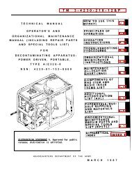
<strong>TM</strong> 3-<strong>4240</strong>-<strong>264</strong>-<strong>12</strong><br />
TECHNICAL MANUAL<br />
OPERATOR’S AND ORGANIZATIONAL<br />
MAINTENANCE MANUAL<br />
SHELTER SYSTEM, COLLECTIVE PROTECTION,<br />
CHEMICAL-BIOLOGICAL: INFLATABLE,<br />
TRAILER-TRANSPORTED, M51<br />
NSN <strong>4240</strong>-00-854-4144<br />
This copy IS a reprint which includes current<br />
pages from Changes 1 through 4.<br />
H E A D Q U A R T E R S, D E P A R T M E N T O F T H E A R M Y<br />
AUGUST 1975
WARNING<br />
Do not unload trailer before lowering rear support leg. Failure to comply may<br />
result in overturning trailer and subsequent injury to personnel and damage to<br />
equipment.<br />
Shelter in carrying case weighs approximately 314 pounds. When lifting, be<br />
careful to avoid injury to personnel, and damage to the <strong>shelter</strong> and carrying case.<br />
Entrance weighs approximately 250 pounds. When lifting, be careful to avoid<br />
injury to personnel and damage to the entrance.<br />
When handling the support rack, keep handles extended out to prevent injury<br />
to fingers.<br />
Be careful when handling entrance. Protect against tears and abrasions.<br />
Failure to comply may result in DEATH or serious illness to occupants.<br />
Be sure that trailer grounding wire is attached to anchor prior to starting<br />
gasoline engine.<br />
DO NOT WALK ON THE FABRIC. Be extremely careful when handling the<br />
<strong>shelter</strong>. Protect against tears and abrasions. Failure to comply may result in<br />
DEATH or serious illness to occupants.<br />
The gas and particulate filters used in the M51 <strong>shelter</strong> system do not provide<br />
protection against carbon monoxide.<br />
Do not apply contents of M11 decontaminating apparatus on hot surfaces.<br />
Container holds combustible DS2 solution.<br />
Use extreme caution when applying heat to engine with open flame. Death or<br />
serious burns may result if flame is concentrated on or near fuel tank.<br />
Avoid vapors and prolonged skin contact with hydraulic lubrication oil.<br />
Failure to comply may result in lung, skin, and eye irritation.<br />
When using the adhesive and cleaning solvent, keep open flame away from<br />
working area. Have working area well ventilated. DEATH or severe burns may<br />
result if personnel fail to observe safety precautions.<br />
The unit commander or senior officer in charge of personnel assigned to<br />
remove and dispose of contaminated gas and particulate filters must prescribe the<br />
necessary protective clothing to be worn during this operation. He must also<br />
prescribe the necessary safety measures to be followed, including the decontamination<br />
operations that must be performed before new filters are installed in<br />
the filter unit (<strong>TM</strong> 3-220).<br />
HIGHLY INFLAMMABLE MATERIAL. When draining gasoline from the<br />
fuel tank, keep open flame away from working area. DEATH or severe burns may<br />
result if personnel fail to observe safety precautions.<br />
When draining gasoline from the fuel tank, use an approved receptacle to<br />
catch the gasoline.<br />
Observe the applicable Surface Danger Zones contained in AR 385-63 for<br />
hazards or ricochet from gunfire.
<strong>TM</strong> 3-<strong>4240</strong>-<strong>264</strong>-<strong>12</strong><br />
C5<br />
CHANGE<br />
NO. 5<br />
HEADQUARTERS<br />
DEPAR<strong>TM</strong>ENT OF THE ARMY<br />
WASHINGTON, DC, 28 May 1990<br />
TECHNICAL MANUAL<br />
OPERATOR’S ORGANIZATIONAL MAINTENANCE MANUAL<br />
FOR<br />
SHELTER SYSTEM COLLECTIVE PROTECTION,<br />
CHEMICAL-BIOLOGICAL: INFLATABLE TRAILER-TRANSPORTED, M51<br />
<strong>TM</strong> 3-<strong>4240</strong>-<strong>264</strong>-<strong>12</strong>, 5 August 1975, and changes 1 thru 4 are changed as follows:<br />
1. The purpose of this change is to update guidance for disposal, handling, and<br />
storage of filters.<br />
2. New or changed material is indicated by a vertical bar in the margin of the<br />
page.<br />
3. Delete entire warning page on inside cover with pen and ink.<br />
4. Remove old pages and insert new pages as follows:<br />
Remove Pages<br />
None<br />
Insert Pages<br />
a and b<br />
4-37 and 4-38 4-37 and 4-38<br />
4-77 and 4-78 4-77 and 4-78<br />
A-1 and A-2 A-1 and A-2<br />
4. File this change sheet in front of the publication for reference purposes.<br />
By Order of the Secretary of the Army:<br />
Official:<br />
CARL E. VUONO<br />
General, United States Army<br />
Chief of Staff<br />
WILLIAM J. MEEHAN II<br />
Brigadier General, United States Army<br />
The Adjutant General<br />
Distribution:<br />
To be distributed in accordance with DA Form <strong>12</strong>-28 (block 137), maintenance<br />
requirements for <strong>TM</strong> 3-<strong>4240</strong>-<strong>264</strong>-<strong>12</strong>.
<strong>TM</strong> 3-<strong>4240</strong>-<strong>264</strong>-<strong>12</strong><br />
C4<br />
CHANGE<br />
HEADQUARTERS<br />
DEPAR<strong>TM</strong>ENT OF THE ARMY<br />
No. 4 WASHINGTON DC, 23 September 1981<br />
Operator’s and Organizational Maintenance Manual<br />
SHELTER SYSTEM, COLLECTIVE PROTECTION, CHEMICAL-BIOLOGICAL:<br />
INFLATABLE, TRAILER-TRANSPORTED, M51<br />
(NSN <strong>4240</strong>-00-854-4144)<br />
<strong>TM</strong> 3-<strong>4240</strong>-<strong>264</strong>-<strong>12</strong>, 29 August 1975, is changed as follows:<br />
1. This change is prepared for replacement of the aluminum fuel tank with a steel fuel tank, and deletion of the fuel<br />
tank drain procedure.<br />
2. Remove old pages and insert new pages as indicated below.<br />
Remove Pages<br />
Insert Pages<br />
3-25 through 3-28 . . . . . . . . . . . . . . . . . . . . . . . . . . . . . . . . . . . . . . . . . . . . . . . . . . . . . . . . . . 3-25 through 3-28<br />
4-61 and 4-62 . . . . . . . . . . . . . . . . . . . . . . . . . . . . . . . . . . . . . . . . . . . . . . . . . . . . . . . . . . . . . . . . .4-61 and 4-62<br />
C-3 through C-6 . . . . . . . . . . . . . . . . . . . . . . . . . . . . . . . . . . . . . . . . . . . . . . . . . . . . . . . . . . . . C-3 through C-6<br />
Index 1 and Index 2 . . . . . . . . . . . . . . . . . . . . . . . . . . . . . . . . . . . . . . . . . . . . . . . . . . . . . . . .Index l and Index 2<br />
3. New or changed material is indicated by a vertical bar in the left margin of the page.<br />
4. File this change sheet in front of the publication for reference purposes.<br />
By Order of the Secretary of the Army:<br />
Official:<br />
E. C. MEYER<br />
General, United States Army<br />
Chief of Staff<br />
ROBERT M. JOYCE<br />
Brigadier General, United States Army<br />
The Adjutant General<br />
Distribution:<br />
To redistributed in accordance with DA Form <strong>12</strong>-28, Operator maintenance requirements for Collective Protection<br />
Equipment, Field and Shelters.
<strong>TM</strong> 3-<strong>4240</strong>-<strong>264</strong>-<strong>12</strong><br />
WARNING<br />
Do not unload trailer before lowering rear support leg. Failure to comply may<br />
result in overturning trailer and subsequent injury to personnel and damage to<br />
equipment.<br />
Shelter in carrying case weighs approximately 314 pounds. When lifting, be<br />
careful to avoid injury to personnel, and damage to the <strong>shelter</strong> and carrying case.<br />
Entrance weighs approximately 250 pounds. When lifting, be careful to avoid<br />
injury to personnel and damage to the entrance.<br />
When handling the support rack, keep handles extended out to prevent injury<br />
to fingers.<br />
Be careful when handling entrance. Protect against tears and abrasions.<br />
Failure to comply may result in DEATH or serious illness to occupants.<br />
Be sure that trailer grounding wire is attached to anchor prior to starting<br />
gasoline engine.<br />
DO NOT WALK ON THE FABRIC. Be extremely Careful when handling the<br />
<strong>shelter</strong>. Protect against tears and abrasions. Failure to comply may result in<br />
DEATH or serious illness to occupants.<br />
The gas and particulate filters used in the M51 <strong>shelter</strong> system do not provide<br />
protection against carbon monoxide.<br />
Do not apply contents of M11 decontaminating apparatus on hot surfaces.<br />
Container holds combustible DS2 solution.<br />
Use extreme caution when applying heat to engine with open flame. Death or<br />
serious burns may result if flame is concentrated on or near fuel tank.<br />
Avoid vapors and prolonged skin contact with hydraulic lubrication oil.<br />
Failure to comply may result in lung, skin, and eye irritation.<br />
When using the adhesive and cleaning solvent, keep open flame away from<br />
working area. Have working area well ventilated. DEATH or severe burns may<br />
result if personnel fail to observe safety precautions.<br />
The unit commander or senior officer in charge of maintenance personnel<br />
assigned to remove the contaminated gas and particulate filters must prescribe<br />
the necessary protective clothing (<strong>TM</strong> 10-277) to be worn during this operation<br />
He must also prescribe the necessary safety measures to be followed including<br />
the NBC decontamination (FM 3-5). This must be performed before the new filters<br />
are installed. Failure to wear protective clothing or follow safety measures<br />
may result in injury or death.<br />
HIGHLY INFLAMMABLE MATERIAL. When draining gasoline from the<br />
fuel tank, keep open flame away from working area. DEATH or severe bums may<br />
result if personnel fail to observe safety precautions.<br />
When draining gasoline from the fuel tank, use an approved receptacle to<br />
catch the gasoline.<br />
Observe the applicable Surface Danger Zones contained in AR 385-63 for<br />
hazards or ricochet from gunfire.<br />
Change 5 a
WARNING<br />
HEALTH/ENVIRONMENTAL HAZARD<br />
Filters use ASC Whetlerite Carbon which contains Chromium VI. Chromium VI<br />
is a known carcinogen if inhaled or swallowed. Damaged or unusable filters<br />
are classified as hazardous waste:<br />
DO NOT throw away damaged or unusable filters as<br />
ordinary trash.<br />
DO turn in damaged or unusable filters to your<br />
hazardous waste management office or Defense<br />
Reutilization and Marketing Office (DRMO).<br />
Filters are completely safe to handle and use if they are not damaged in<br />
such a way that carbon leaks from them. In unlikely event that carbon<br />
should leak, use protection such as a dust respirator to cover nose and<br />
mouth and put carbon in container such as self-sealing plastic bag; turn<br />
in to hazardous waste management office or DRMO.<br />
Disposal of hazardous waste is restricted by the Resource Conservation and<br />
Recovery Act as amended (42 U.S.C.A sec 6901 et seq). Violation of these<br />
laws is subject to severe criminal penalties.<br />
b Change 5
<strong>TM</strong> 3-<strong>4240</strong>-244-<strong>12</strong><br />
TECHNICAL MANUAL<br />
HEADQUARTERS<br />
DEPAR<strong>TM</strong>ENT OF THE ARMY<br />
No. 3-<strong>4240</strong>-<strong>264</strong>-<strong>12</strong> WASHINGTON, D. C., 29 August 1976<br />
OPERATORS AND ORGANIZATIONAL MAINTENANCE MANUAL<br />
SHELTER SYSTEM, COLLECTIVE PROTECTION<br />
CHEMICAL-BIOLOGICAL:<br />
INFLATABLE,<br />
TRAILER-TRANSPORTED, M51<br />
(NSN <strong>4240</strong>-00-854-4144)<br />
Paragraph<br />
Page<br />
CHAPTER<br />
Section<br />
1.<br />
I.<br />
II.<br />
INTRODUCTION<br />
General 1-1<br />
Description and data . . . . . . . . . . . . . . . . . . . . . . . . . . . . . . . . . . . . . . . . . . . . . . .1-3<br />
1-1<br />
1-1<br />
CHAPTER<br />
Section<br />
2.<br />
I.<br />
II.<br />
III.<br />
IV.<br />
V.<br />
VI.<br />
VII.<br />
VIII.<br />
OPERATING INSTRUCTIONS<br />
Controls 2-1<br />
Instruments and indicator lights . . . . . . . . . . . . . . . . . . . . . . . . . . . . . . . . . . . . . . . . . . . .2-27<br />
Operation under usual conditions . . . . . . . . . . . . . . . . . . . . . . . . . . . . . . . . . . . . . . . . . . . 2-42<br />
Erection and operation of <strong>shelter</strong> and ante-room in chemical-biological environment . . . . . . . . . . . 2-57<br />
Operation of material used in conjunction with major items . . . . . . . . . . . . . . . . . . . . . 2-62<br />
Operation under unusual conditions . . . . . . . . . . . . . . . . . . . . . . . . . . . . . . . . . . . . . . .2-64<br />
Tandem installation 2-72<br />
Tools and equipment 2-77<br />
2-1<br />
2-10<br />
2-<strong>12</strong><br />
2-49<br />
2-55<br />
2-57<br />
2-64<br />
2-68<br />
CHAPTER<br />
Section<br />
CHAPTER<br />
Section<br />
3.<br />
I.<br />
II.<br />
III.<br />
IV.<br />
V.<br />
VI.<br />
VII.<br />
VIII.<br />
IX.<br />
X.<br />
4.<br />
I.<br />
II.<br />
III.<br />
IV.<br />
V.<br />
VI.<br />
VII.<br />
VIII.<br />
IX.<br />
X.<br />
XI.<br />
XII.<br />
XIII.<br />
XIV.<br />
XV.<br />
XVI.<br />
XVII.<br />
XVIII.<br />
XIX.<br />
XX.<br />
XXI.<br />
OPERATOR’S MAINTENANCE INSTRUCTIONS<br />
Preventive maintenance checks and services . . . . . . . . . . . . . . . . . . . . . . . . . . . . . . . . . . . . . . 3-1<br />
Troubleshooting 3-3<br />
Lubrication 3-5<br />
Special tools and equipment 3-10<br />
Inflatable <strong>shelter</strong> 3-<strong>12</strong><br />
Inflatable entrance, switch box, and distribution box . . . . . . . . . . . . . . . . . . . . . . . . . . . . 3-20<br />
Trailer mounted and miscellaneous equipment . . . . . . . . . . . . . . . . . . . . . . . .3-24<br />
Stenciling 3-29<br />
Filterchanqe criteria . . . . . . . . . . . . . . . . . . . . . . . . . . . . . . . . . . . . . . . . . . . . . .3-33<br />
Trailer Replacement, M68 (Maintenance Float) . . . . . . . . . . . . . . . . . . . . . . . . . . . . . . . . . .3-35 3-34<br />
ORGANIZATIONAL MAINTENANCE INSTRUCTIONS<br />
Service upon receipt of materiel 4-1 4-1<br />
Organizational preventive maintenance checks and services 4-7 4-9<br />
Troubleshooting 4-9 4-10<br />
Carrying case 4-11 4-<strong>12</strong><br />
Inflatable <strong>shelter</strong> 4-14 4-14<br />
Inflatable entrance 4-17 4-16<br />
Switch box 4-32 4-28<br />
Distribution box 4-37 4-33<br />
Entrance gas-particulate filter unit 4-40 4-36<br />
Auxiliary control indicator 4-50 4-38<br />
Tailgate extension, support rack, and <strong>shelter</strong> support pin assemblies . . . . . . . . . . . . . . . . . . . . . . . . . .4-59 4-46<br />
Evacuation fan 4-62 4-52<br />
Shelter air duct, evaucation manifold, airduct hose, and storage retainers . . . . . . . . . . . . . . . . . . . . . . . .4-67 4-54<br />
Cable and light assemblies 4-71 4-56<br />
Drivebelts 4-73 4-58<br />
Main control indicator 4-76 4-59<br />
Fuel system 4-80 4-59<br />
Gasoline engine 4-91 4-63<br />
Environmental equipment cabinet 4-96 4-65<br />
Recirculation filter cabinet 4-99 4-71<br />
Shelter recirculation fan cabinet and evaporator fan . . . . . . . . . . . . . . . . . . . . . . . . . . . . . . . . . . . . . . . . .4-102 4-73<br />
XXII. Gas-particulate filter assembly 4-104 4-77<br />
3-1<br />
3-3<br />
3-7<br />
3-9<br />
3-9<br />
3-18<br />
3-20<br />
3-28<br />
3-34<br />
Change 3 i
<strong>TM</strong> 3-<strong>4240</strong>-<strong>264</strong>-<strong>12</strong><br />
CHAPTER<br />
4.<br />
XXIII.<br />
XXIV.<br />
XXV.<br />
XXVI.<br />
XXVII.<br />
XXVIII.<br />
Paragraph<br />
ORGANIZATIONAL MAINTENANCE INSTRUCTIONS–Continued<br />
Generator . . . . . . . . . . . . . . . . . . . . . . . . . . . . . . . . . . . . . . . . . . . . . . . . . . . . . . . . . . . . . . . . . . . . . . . . . . . . ..4-103<br />
Centrifugal blower. . . . . . . . . .. . . . . . . . . . . . . . . . . . . . . . . . . . . . . . . . . . . . . . . . . . . . . . . . . . . . . . . . . . .4-111<br />
Condenser fan. . . . . . . . . . . . . . . . . . . . . . . . . . . . . . . . . . . . . . . . . . . . . . . . . . . . . . . . . . . . . . . .4-116<br />
Trailer-mounted and miscellaneous equipment . . . . . . . . . . . . . . . . . . . . . . . . . . . . . . . . . . . . . . . .4-119<br />
Air-flow gage. . . . . . . . . . . . . . . . . . . . . . . . . . . . . . . . . . . . . . . . . . . . . . . . . . . . . . . . . . . 4-l44<br />
Painting. . . . . . . . . . . . . . . . . . . . . . . . . . . . . . . . . . . . . . . . . . . . . . . . . . . . . . . . . . . . . . . . . . . . . . . . . . . . . . . . . . . . . . .4-149<br />
Page<br />
4-79<br />
4-81<br />
4-86<br />
4-88<br />
4-99<br />
4-101<br />
CHAPTER<br />
Section<br />
5.<br />
I.<br />
II.<br />
SHIPMENT, ADMINISTRATIVE STORAGE, AND DESTRUCTION TO PREVENT ENEMY USE<br />
Shipment and administrative storage . . . . . . . . . . . . . . . . . . . . . . . . . . . . . . . . . . . . . . . . . . . . . . . . . . . . 5-1<br />
Destruction to prevent enemy use . . . . . . . . . . . . . . . . . . . . . . . . . . . . . . . . . . . . . . . . . . . . . . . . . . . . 5-3<br />
5-1<br />
5-1<br />
APPENDIX.<br />
A.<br />
REFERENCES. . . . . . . . . . . . . . . . . . . . . . . . . . . . . . . . . . . . . . . . . . . . . . . . . . . . . . . . .<br />
A-1<br />
APPENDIX<br />
Section<br />
B.<br />
I.<br />
II.<br />
BASIC ISSUE ITEMS LIST AND ITEMS TROOP INSTALLED OR AUTHORIZED LIST<br />
Introduction . . . . . . . . . . . . . . . . . . . . . . . . . . . . . . . . . . . . . . . . . . . . . . . . . . . . . .. . . . . . . . . . . B-1 B-1<br />
Basic issue items list . . . . . . . . . . . . . . . . . . . . . . . . . . . . . . . . . . . . . . . . . . . . . . . . . . . . Not Applicable<br />
APPENDIX<br />
Section<br />
INDEX<br />
C.<br />
I.<br />
II.<br />
MAINTENANCE ALLOCATION CHART<br />
Introduction<br />
C-1<br />
Maintenance allocation chart. . . . . . . . . . . . . . . . . . . . . . . . . . . . . . . . . . . . .<br />
. . . . . . . . . . . . . . . . . . . . . . . . . . . . . . . . . . . . . . . . . . . . . . . . . . . . . .<br />
C-l<br />
Index 1<br />
Figure<br />
No.<br />
1-1<br />
1-1<br />
1-2<br />
1-3<br />
1-4<br />
1-5<br />
1-6<br />
1-7<br />
1-8<br />
1-9<br />
1-10<br />
1-11<br />
1-<strong>12</strong><br />
1-13<br />
1-14<br />
1-15<br />
1-15<br />
2-1<br />
2-2<br />
2-3<br />
2-4<br />
2-5<br />
2-6<br />
2-7<br />
2-8<br />
2-9<br />
2-10<br />
2-11<br />
2-<strong>12</strong><br />
2-13<br />
2-14<br />
2-15<br />
2-16<br />
2.16<br />
2-17<br />
2-18<br />
2-19<br />
LIST OF ILLUSTRATIONS<br />
Title<br />
M51 inflatable chemical-biological collective protection <strong>shelter</strong> system (sheet l of 2) . . . . . . . . . . . . . . . . . .<br />
M51 inflatable chemical-biological collective protection <strong>shelter</strong> system (sheet 2 of 2) . . . . . . . . . . . . . . . . . .<br />
Inflatable entrance and <strong>shelter</strong> . . . . . . . . . . . . . . . . . . . . . . . . . . . . . . . . . . . . . . . . . . . .<br />
Entrance gas-particulate filter unit and auxiliary control indicator . . . . . . . . . . . . . . . . . . . . . . . . . . . . . . . . .<br />
Air ducts, air duct hose, and plenums . . . . . . . . . . . . . . . . . . . . . . . . . . . . . . . . . . . .<br />
Electrical cables . . . . . . . . . . . . . . . . . . . . . . . . . . . . . .<br />
Shelter carrying case and support rack . . . . . . . . . . . . . . . . . . . . . . . . . . .<br />
Major trailer-mounted equipment . . . . . . . . . . . . . . . . . . . . . . . . . . . . . . . . .<br />
Accessories<br />
Accessories<br />
Accessories<br />
Accessories<br />
Shelter system air and refrigerant flow diagram . . . . . . . . . . . . . . . . . . . . . . . . . . . . . . . . .<br />
Make-up, inflation, filtration, and pressurized system, block diagram . . . . . . . . . . . . . . . . . . . . . . . . . . . . . .<br />
Environmental control system and entrance recirculation system, block diagram . . . . . . . . . . . . . . . . . . . . .<br />
Identification and instruction plates, and markings (sheet l of 2) . . . . . . . . . . . . . . . . . . . . .<br />
Identification and instruction plates, and markings (sheet 2 of 2) . . . . . . . . . . . . . . . . . . . . . . . . . .<br />
Controls and instruments<br />
Main control indicator<br />
Auxiliary control indicator<br />
Controls and instruments<br />
Controls and instruments<br />
Controls and instruments .<br />
Position of equipment prior to inflation<br />
Shelter unloading<br />
lnflatable entrance and support rack unloading . . . . . . . . . . . . . . . . . . . . . . . . . . . . . . . . . ..<br />
Removable items . . . . . . . . . . . . . . . . . . . . . . . . . . . . . . . . . . . . . . . . . . . . . . . . . . . . . . . . . .<br />
Box and sound-attenuating plenums installation . . . . . . . . . . . . . . . . . . . . . . . . . . . . . . . . . . . .<br />
Positioning entrance for inflation<br />
Positioning <strong>shelter</strong> for inflation . . . . . . . . . . . . . . . . . . . . . . . . . . . . .<br />
Entrance and <strong>shelter</strong> connection<br />
Arctic blanket folding sequence<br />
Anchors and tent pins installation (sheet l of 2)<br />
Anchors and tent pins installation (sheet 2 of 2). . . . . . . . . . . . . . . . . . . . . . . . . . . . . . . . . . . . . .<br />
Air-supply, air-return, and air-recirculation duct storage . . . . . . . . . . . . . . . . . . . . . . . . . . . . . . . . . . . . . .<br />
Air-return and air supply duct installation . . . . . . . . . . . . . . . . . . . . . . . . . . . . . . . . . . . . . . . . . . . . . . . . . . . .<br />
Electrical cables installation . . . . . . . . . . . . . . . . . . . . . . . . . . . . . . . . . .<br />
Page<br />
1-2<br />
1-3<br />
1-5<br />
1-7<br />
1-8<br />
1-10<br />
1-11<br />
1-13<br />
1-15<br />
1-17<br />
1-19<br />
1-21<br />
1-23<br />
1-24<br />
1-26<br />
1-28<br />
1-29<br />
2-2<br />
2-3<br />
2-5<br />
2-7<br />
2-9<br />
2-11<br />
2-13<br />
2-14<br />
2-16<br />
2-18<br />
2-20<br />
2-22<br />
2-24<br />
2-26<br />
2-28<br />
2-30<br />
2-31<br />
2-32<br />
2-33<br />
2-35<br />
ii
<strong>TM</strong> 3-<strong>4240</strong>-<strong>264</strong>-<strong>12</strong><br />
2-19.1<br />
2-20<br />
2-21<br />
2-22<br />
2-23<br />
2-24<br />
2-25<br />
2-26<br />
2-27<br />
2-28<br />
2-29<br />
2-30<br />
2-31<br />
2-32<br />
2-33<br />
3-1<br />
3-2<br />
3-3<br />
3-4<br />
3-5<br />
3-6<br />
3-7<br />
3-8<br />
3-9<br />
3-10<br />
3-11<br />
3-<strong>12</strong><br />
3-<strong>12</strong><br />
3-<strong>12</strong><br />
3-<strong>12</strong><br />
3-<strong>12</strong><br />
3-13<br />
4-1<br />
4-2<br />
4-3<br />
4-4<br />
4-5<br />
4-6<br />
4-7<br />
4-8<br />
4-9<br />
4-10<br />
4-11<br />
4-<strong>12</strong><br />
4-<strong>12</strong><br />
4-13<br />
4-14<br />
4-15<br />
4-16<br />
4-17<br />
4-18<br />
4-19<br />
4-20<br />
4-21<br />
4-22<br />
4-23<br />
4-24<br />
4-25<br />
4-26<br />
4-27<br />
4-28<br />
4-29<br />
4-30<br />
4-31<br />
4-32<br />
4-33<br />
4-34<br />
Figure Title Page<br />
No.<br />
Governor adjustment . . . . . . . . . . . . . . . . . . . . . . . . . . . . . . . . . . . . . . . . . . . . . . . . . . . . . . . . . . . 2-37<br />
Air pressure taps . . . . . . . . . . . . . . . . . . . . . . . . . . . . . . . . . . . . . . . . . . . . . . . . . . . . . 2-39<br />
Altitude correction chart . . . . . . . . . . . . . . . . . . . . . . . . . . . . . . . . . . . . . . . . . . . . . . . . . . . . .2-41<br />
Entrance preparation for storage . . . . . . . . . . . . . . . . . . . . . . . . . . . . . . . . . . . . . . . . . . . . . . . . . . .2-45<br />
Shelter and entrance evacuation hookup . . . . . . . . . . . . . . . . . . . . . . . . . . . . . . . . . . . . . . . . . . . . . . . . .2-46<br />
Shelter folding and storage . . . . . . . . . . . . . . . . . . . . . . . . . . . . . . . . . . . . . . . . . . . . . . . . . . 2-48<br />
Shelter system erection in chemical-biological environment . . . . . . . . . . . . . . . . . . . . . . . . . . . . . . . . . . . . . 2-51<br />
Ante-room erection . . . . . . . . . . . . . . . . . . . . . . . . . . . . . . . . . . . . . . . . . . . . . . . . . . . . . 2-54<br />
Fire extinguisher and usage . . . . . . . . . . . . . . . . . . . . . . . . . . . . . . . . . . . . . . . . . . . . . . .2-56<br />
Erection of sun canopy . . . . . . . . . . . . . . . . . . . . . . . . . . . . . . . . . . . . . . . . . . . . . . . . . . . . . . . . .2-59<br />
Installation of <strong>shelter</strong> supports . . . . . . . . . . . . . . . . . . . . . . . . . . . . . . . . . . . . . . . . . . . . . 2-61<br />
Evacuation fan , . . . . . . . . . . . . . . . . . . . . . . . . . . . . . . . . . . . . . . . . . . . . . . . . . 2-63<br />
Shelter to <strong>shelter</strong> installation . . . . . . . . . . . . . . . . . . . . . . . . . . . . . . . . . . . . . . . . . . . . . . . . .2-66<br />
Entrance-to-<strong>shelter</strong> installation . . . . . . . . . . . . . . . . . . . . . . . . . . . . . . . . . . . . . . . . . . . . . . . 2-67<br />
Tools and equipment . . . . . . . . . . . . . . . . . . . . . . . . . . . . . . . . . . . . . . . . . . . . . . . . . . . 2-69<br />
Battery terminals . . . . . . . . . . . . . . . . . . . . . . . . . . . . . . . . . . . . . . . . . . . . . . . . . . . . . . . . . . . . . . 3-5<br />
Centrifugal blower and gasoline engine lubrication . . . . . . . . . . . . . . . . . . . . . . . . . . . . . . . . . . . . . . . . . 3-8<br />
Stitching pattern . . . . . . . . . . . . . . . . . . . . . . . . . . . . . . . . . . . . . . . . . . . . . . . . . . . . . . . . . . . . . . . . . . 3-10<br />
Mounting plates, air-conditioniing duct, and rings, exploded view . . . . . . . . . . . . . . . . . . . . . . . . . 3-14<br />
Removable wall section, exploded view . . . . . . . . . . . . . . . . . . . . . . . . . . . . . . . . . . . . . . . . . . . . . . . 3-16<br />
Entrance and <strong>shelter</strong> tiedown ropes fabrication . . . . . . . . . . . . . . . . . . . . . . . . . . . . . . . . . . . . . . . . . . . . . . 3-17<br />
Incandescent lamps, exploded view . . . . . . . . . . . . . . . . . . . . . . . . . . . . . . . . . . . . . . . . . . . . . . . . . . 3-18<br />
Main control indicator, exploded view . . . . . . . . . . . . . . . . . . . . . . . . . . . . . . . . . . . . . . . . . . . . . . . . . . . . . . . . 3-21<br />
Special tool . . . . . . . . . . . . . . . . . . . . . . . . . . . . . . . . . . . . . . . . . . . . . . . . . . . . . . . . . . . . . 3-23<br />
Drivebelt adjustment . . . . . . . . . . . . . . . . . . . . . . . . . . . . . . . . . . . . . . . . . . . . . . 3-25<br />
Fuel tank strainer, gage, switch, and pump, exploded view. . . . . . . . . . . . . . . . . . . . . . . . . . . . . . . . . . . . . . . . 3-27<br />
Stencil requirements and location (sheet l of 5) . . . . . . . . . . . . . . . . . . . . . . . . . . . . . . . . . . . . . . . . . . . . . . . . . . 3-29<br />
Stencil requirments and location (sheet 2 of 5) . . . . . . . . . . . . . . . . . . . . . . . . . . . . . . . . . . . . . . . . . . . . . . . . . . . 3-30<br />
Stencil requirements and location( sheet 3 of 5) . . . . . . . . . . . . . . . . . . . . . . . . . . . . . . . . . . . . . . . . . . . . . . . . . . 3-31<br />
Stencil requirements and location (sheet 4 of 5) . . . . . . . . . . . . . . . . . . . . . . . . . . . . . . . . . . . . . . . . . . . . . . . . . . 3-32<br />
Stencil requirements and location (sheet 5 of 6) . . . . . . . . . . . . . . . . . . . . . . . . . . . . . . . . . . . . . . . . . . . . . . . . 3-33<br />
Trailer replacement, M68 (Maintenance Float) . . . . . . . . . . . . . . . . . . . . . . . . . . . . . . . . . . . . . . . . .<br />
Shelter system, packaged for transit . . . . . . . . . . . . . . . . . . . . . . . . . . . . . . . . . . . . . . . . . . . . . . . . . . . . . . . . . . . . .<br />
Gas-particulate filter assembly, exploded view . . . . . . . . . . . . . . . . . . . . . . . . . . . . . . . . . . . . . . . . . . . . . . . . . .<br />
Gas and particulate filter installation, and <strong>shelter</strong> side support, exploded view . . . . . . . . . . . . . . . . . . . . . . .<br />
Entrance gas-particulate filter unit, exploded view . . . . . . . . . . . . . . . . . . . . . . . . . . . . . . . . . . . . . . . . . . . . . . . .<br />
Shelter carrying case, exploded view . . . . . . . . . . . . . . . . . . . . . . . . . . . . . . . . . . . . . . . . . . . . . . . . . . . . . . . . . . . .<br />
Connector, exploded view . . . . . . . . . . . . . . . . . . . . . . . . . . . . . . . . . . . . . . . . . . . . . . . . . . . . . . . .<br />
Inflatable entrance, exploded view . . . . . . . . . . . . . . . . . . . . . . . . . . . . . . . . . . . . . . . . . . . . . . . . . . . . . . .<br />
Eave trough and zipper retainer, exploded view . . . . . . . . . . . . . . . . . . . . . . . . . . . . . . . . . . . . . . . . . . . . . . . . . .<br />
Retaining cord fabrication. . . . . . . . . . . . . . . . . . . . . . . . . . . . . . . . . . . . . . . . . . . . . . . . . . . . . . . . . . . . . . . . .<br />
Doors, exploded view . . . . . . . . . . . . . . . . . . . . . . . . . . . . . . . . . . . . . . . . . . . . . . . . . . . . . . . . . . . . . .<br />
Damper flap fabrication . . . . . . . . . . . . . . . . . . . . . . . . . . . . . . . . . . . . . . . . . . . . . . . . . . . . . . . . . . . . . . . . . . . . . . .<br />
Gasket fabrication (sheet l of 2) . . . . . . . . . . . . . . . . . . . . . . . . . . . . . . . . . . . . . . . . . . . . . . . . . . . . . . . .<br />
Gasket fabrication (sheet 2 of 2) . . . . . . . . . . . . . . . . . . . . . . . . . . . . . . . . . . . . . . . . . . . . . . . . . . . . . . . . . . . . . . .<br />
Seal-retaining frame, exploded view . . . . . . . . . . . . . . . . . . . . . . . . . . . . . . . . . . . . . . . . . . . . . . . . . . . . . . . . . . . .<br />
Switch box, exploded view . . . . . . . . . . . . . . . . . . . . . . . . . . . . . . . . . . . . . . . . . . . . . . . . . . . . . . . . . . . . .<br />
Switch and distribution box gasket fabrication . . . . . . . . . . . . . . . . . . . . . . . . . . . . . . . . . . . . . . . . . . . . . . . . . . .<br />
Switch box wiring diagram . . . . . . . . . . . . . . . . . . . . . . . . . . . . . . . . . . . . . . . . . . . . . . . . . . . . . . . . . . . . . . . . .<br />
Distribution box exploded view . . . . . . . . . . . . . . . . . . . . . . . . . . . . . . . . . . . . . . . . . . . . . . . . . . . . . . . . . . .<br />
Fan gasket tabrication . . . . . . . . . . . . . . . . . . . . . . . . . . . . . . . . . . . . . . . . . . . . . . . . . . . . .<br />
Auxiliary control indicator, exploded view . . . . . . . . . . . . . . . . . . . . . . . . . . . . . . . . . . . . . . . . . . . . . . . . .<br />
Auxiliary control indicator wiring diagram legend . . . . . . . . . . . . . . . . . . . . . . . . . . . . . . . . . . . . . . . . . . . . . . .<br />
Auxiliary control indicator details, exploded view . . . . . . . . . . . . . . . . . . . . . . . . . . . . . . . . . . . . . . . . . . . . . . . .<br />
Tailgate extension, exploded view . . . . . . . . . . . . . . . . . . . . . . . . . . . . . . . . . . . . . . . . . . . . . . . . . . . . . . . . . .<br />
Support rack, exploded view . . . . . . . . . . . . . . . . . . . . . . . . . . . . . . . . . . . . . . . . . . . . . . . . . . . . . . . . . . . . . . . . . . .<br />
Shelter support pin, exploded view . . . . . . . . . . . . . . . . . . . . . . . . . . . . . . . . . . . . . . . . . . . . . . . . . . . . . . . . . . . .<br />
Evacuation fan, exploded view . . . . . . . . . . . . . . . . . . . . . . . . . . . . . . . . . . . . . . . . . . . . . . . . . . . . . . . . . . . . . . .<br />
Shelter air ducts, air duct hose, and evacuation manifold, exploded view . . . . . . . . . . . . . . . . . . . . . . . . . . .<br />
Cable and light assemblies, exploded view . . . . . . . . . . . . . . . . . . . . . . . . . . . . . . . . . . . . . . . . . . . . . . . . . . . . . . .<br />
Pad fabrication . . . . . . . . . . . . . . . . . . . . . . . . . . . . . . . . . . . . . . . . . . . . . . . . . . . . . . . . . . .<br />
Fuel gage wiring diagram . . . . . . . . . . . . . . . . . . . . . . . . . . . . . . . . . . . . . . . . . . . . . . . . . . . . . . . . . . . .<br />
Throttle, air duct hose, and oil drain, exploded view . . . . . . . . . . . . . . . . . . . . . . . . . . . . . . . . . . . . . . . . . . . . . .<br />
Environmental and miscellaneous equipment, exploded view. . . . . . . . . . . . . . . . . . . . . . . . . . . . . . . . . . . . . . .<br />
Heater access panel gasket fabrication . . . . . . . . . . . . . . . . . . . . . . . . . . . . . . . . . . . . . . . . . . . . . . . . . . . . . . . . . .<br />
Refrigerant access cover gasket fabrication . . . . . . . . . . . . . . . . . . . . . . . . . . . . . . . . . . . . . . . . . . . . . . . . . . .<br />
Heater electrical power cable.. . . . . . . . . . . . . . . . . . . . . . . . . . . . . . . . . . . . . . . . . . . . . . . . . . . . . . . . . .<br />
3-34<br />
4-1<br />
4-4<br />
4-6<br />
4-8<br />
4-13<br />
4-15<br />
4-17<br />
4-19<br />
4-20<br />
4-21<br />
4-23<br />
4-26<br />
4-26<br />
4-27<br />
4-29<br />
4-31<br />
4-33<br />
4-35<br />
4-37<br />
4-39<br />
4-41<br />
4-43<br />
4-47<br />
4-49<br />
4-51<br />
4-63<br />
4-55<br />
4-57<br />
4-60<br />
4-61<br />
4-64<br />
4-66<br />
4-68<br />
4-69<br />
4-70<br />
Change 3<br />
iii
<strong>TM</strong> 3-<strong>4240</strong>-<strong>264</strong>-<strong>12</strong><br />
Figure<br />
No.<br />
4-35<br />
4-36<br />
4-37<br />
4-38<br />
4-39<br />
4-40<br />
4-41<br />
4-42<br />
4-43<br />
4-44<br />
4-45<br />
4-46<br />
4-47<br />
4-48<br />
4-49<br />
4-50<br />
FO-1<br />
FO-2<br />
Title<br />
Access cover gasket fabrication . . . . . . . . . . . . . . . . . . . . . . . . . . . . . . . . . . . . . . . . . . . . . . . . . . . . . 4-72<br />
Shelter recirculation fan cabinet and evaporation fan, exploded view .. . . . . . . . . . . . . . . . . . . . . 4-74<br />
Access cover gasket fabrication . . . . . . . . . . . . . . . . . . . . . . . . . . . . . . . . . . . . . . . . . . . . . . 4-75<br />
Evaporator fan gasket fabrication . . . . . . . . . . . . . . . . . . . . . . . . . . . . . . . . . . . . . . . . . . . . 4-77<br />
Generator and voltage regulator, exploded view . . . . . . . . . . . . . . . . . . . . . . . . . . . . . . . . . . . . 4-80<br />
Centrifugal blower, plenum, and mounting plate, exploded view . . . . . . . . . . . . . . . . . . . . . . . . . . . . . . . . . . .4-82<br />
Pulley removal . . . . . . . . . . . . . . . . . . . . . . . . . . . . . . . . . . . . . . . . . . . . . . . . . . . . . . . . . . . . . . . . . . 4-84<br />
Pulley installation . . . . . . . . . . . . . . . . . . . . . . . . . . . . . . . . . . . . . . . . . . . . . . . . . . . . . . . . . . . . . . . . . 4-85<br />
Condenser fan, exploded view . . . . . . . . . . . . . . . . . . . . . . . . . . . . . . . . . . . . . . . . . . . 4-87<br />
Latches (box and sound-attenuating plenum;, exploded view . . . . . . . . . . . . . . . . . . . . . . . . . . . . . . . . . . . . . . . 4-89<br />
Miscellaneous trailer-mounted equipment, exploded view . . . . . . . . . . . . . . . . . . . . . . . . . . . . . . . . . . . 4-90<br />
Bracket pad fabrication . . . . . . . . . . . . . . . . . . . . . . . . . . . . . . . . . . . . . . . . . . . . . . . . . . . 4-91<br />
Ground, wire, battery, baffle, identification plate, and fire extinguisher bracket, exploded view . . . . . . . . . . 4-94<br />
Insulation sheet fabrication . . . . . . . . . . . . . . . . . . . . . . . . . . . . . . . . . . . . . . . . . . . . . . . . . . . . . . . . 4-96<br />
Trailer-mounted tiedown straps, exploded view . . . . . . . . . . . . . . . . . . . . . . . . . . . . . . . . . . . . . . . . . . .4-98<br />
Air-flow gage, exploded view . . . . . . . . . . . . . . . . . . . . . . . . . . . . . . . . . . . . . . . . . . . . . . . . . . 4-100<br />
Electrical schematic . . . . . . . . . . . . . . . . . . . . . . . . . . . . . . . . . . . . . . . . . . . . . . . . . . . . . .<br />
Electrical wiring diagram . . . . . . . . . . . . . . . . . . . . . . . . . . . . . . . . . . . . . . . . . . . . . . . . . . . . . . . . . . . . . . .<br />
Page<br />
LIST OF TABLES<br />
Table<br />
Title<br />
Page<br />
1-1<br />
1-2<br />
1-3<br />
3-1<br />
3-2<br />
3-4<br />
3-5<br />
4-1<br />
4-2<br />
4-3<br />
C-1<br />
Tool box contents . . . . . . . . . . . . . . . . . . . . . . . . . . . . . . . . . . . . . . . . . . . . . . . . . . . . . . . . . . . . 1-20<br />
Repair kit contents . . . . . . . . . . . . . . . . . . . . . . . . . . . . . . . . . . . . . . . . . . . . 1-22<br />
Expendable items . . . . . . . . . . . . . . . . . . . . . . . . . . . . . . . . . . . . . . . . . . . . . . . . . . 1-31<br />
Operator/crew preventive maintenance checks and services . . . . . . . . . . . . . . . . . . . . . . . . . . . . . . . . . . . . . . . . 3-1<br />
Operator/crew troubleshooting . . . . . . . . . . . . . . . . . . . . . . . . . . . . . . . . . . 3-4<br />
Special tools and equipment . . . . . . . . . . . . . . . . . . . . . . . . . . . . . . . . . . . . . . . . . . . . . . 3-9<br />
Drivebelt tension . . . . . . . . . . . . . . . . . . . . . . . . . . . . . . . . . . . . . . . . . . . . . . . . . . . . . . . . . . . . . . . . . . . 3-23<br />
Filter change criteria . . . . . . . . . . . . . . . . . . . . . . . . . . . . . . . . . . . . . . . . . . . . . . . . . . . . . . . . . . . . . 3-34<br />
Miscellaneous tools and items not installed . . . . . . . . . . . . . . . . . . . . . . . . . . . . . . . . . . . . 4-3<br />
Organizational preventive maintenance checks and services . . . . . . . . . . . . . . . . . . . . . . . . . . . . . . . . . . . . . . . . 4-10<br />
Organizational troubleshooting . . . . . . . . . . . . . . . . . . . . . . . . . . . . . . . . . . . . . . . . . . . . . . . 4-11<br />
Tool and test equipment requirements . . . . . . . . . . . . . . . . . . . . . . . . . . . . . . . . . . . . . . . . . . . . . . . . . . . . C-6<br />
iv Change 3
<strong>TM</strong> 3-<strong>4240</strong>-<strong>264</strong>-<strong>12</strong><br />
CHAPTER 1<br />
INTRODUCTION<br />
Section I. GENERAL<br />
1–1. Scope<br />
These instructions are for use by the crew, operator,<br />
and organizational maintenance personnel.<br />
They apply to the M51 trailer-transported inflatable<br />
chemical-biological collective protection <strong>shelter</strong><br />
system, hereinafter, referred teas the <strong>shelter</strong><br />
system. The instructions contain information on<br />
the erection, operation, and maintenance of the<br />
equipment, as well as a description of the major<br />
systems and components and their functions in<br />
relation to other systems and components of the<br />
equipment.<br />
1-2. Record and Report Forms<br />
a. Equipment maintenance forms and procedures<br />
for their use are prescribed in <strong>TM</strong> 38-750.<br />
b. You can improve this <strong>manual</strong> by recommending<br />
changes using DA Form 2028 (Recommended<br />
Changes to Publications and Blank Forms) or DA<br />
Form 2028-2 (Test) (Recommended Changes to<br />
Equipment Technical Manuals), located in the<br />
back of this <strong>manual</strong>. Mail the form direct to Commander,<br />
US Army Armament Materiel Readiness<br />
Command, ATTN: DRSAR–MAS–C, Aberdeen<br />
Proving Ground, MD 21010. A reply will be furnished<br />
to you.<br />
Section Il.<br />
DESCRIPTION DATA<br />
1–3. General<br />
The <strong>shelter</strong> system (fig. 1-1) is a self-contained<br />
unit, designed to provide collective protection for<br />
10 occupants against all known chemical-biological<br />
(CB) agents. It normally is deployed whenever<br />
a CB attack is anticipated or imminent. Using<br />
alternate erection procedures, it can be deployed<br />
during or immediately after a CB attack (contaminated<br />
environment). The <strong>shelter</strong> system can<br />
be stored or used in most climates and erected on<br />
most terrains. In normal weather, four men and a<br />
crew chief can remove the <strong>shelter</strong> system from the<br />
trailer and erect it in approximately 30 minutes.<br />
Disassembly and return to the transit configuration<br />
can also be accomplished in approximately 30<br />
minutes. Basically the <strong>shelter</strong> system consists of<br />
an inflatable entrance, an inflatable <strong>shelter</strong>, a military<br />
standard gasoline engine, a gas-particulate<br />
filter assembly, an air conditioning system, heating<br />
system, centrifugal blower, generator, an entrance<br />
gas-particulate filter unit, an air-evacuation<br />
fan, emergency <strong>shelter</strong> supports, and the<br />
necessary cables, controls, and flexible ducts. A<br />
modified 2-wheel military standard model<br />
M105A2, 1½-ton trailer transports the system.<br />
The entire system can be air-dropped.<br />
Change 3 1-1
<strong>TM</strong> 3-<strong>4240</strong>-<strong>264</strong>-<strong>12</strong><br />
RIGHT FRONT THREE-QUARTER VIEW<br />
TOP VIEW<br />
LEFT FRONT THREE-QUARTER VIEW<br />
1-2 Change 3<br />
Figure 1-1 M51 inflatable chemical-biological collective protection <strong>shelter</strong> system (sheet 1 of 2).
<strong>TM</strong> 3-<strong>4240</strong>-<strong>264</strong>-<strong>12</strong><br />
Figure 1-1 M51 inflatable chemical-biological collective protection <strong>shelter</strong> system (sheet 2 of 2).<br />
1-3
<strong>TM</strong> 3-<strong>4240</strong>-<strong>264</strong>-<strong>12</strong><br />
1-4. Inflatable Entrance<br />
The entrance (fig. 1-2) is a double-walled, airinflatable,<br />
self-supporting structure. The integral<br />
walls and floor are made of material impermeable<br />
to CB agents. Each end of the entrance has a<br />
metal door frame in which are mounted doublehung<br />
doors. One door at each end of the entrance<br />
has a window; the other door has an airflow<br />
control butterfly valve to maintain a predetermined<br />
air pressure within the entrance and<br />
<strong>shelter</strong>. The entrance incorporates a distribution<br />
box, a switch box, an inflation fitting, interconnecting<br />
fittings, air-recirculation outlet and<br />
inlet connections, and tiedown ropes. The purpose<br />
of the entrance is to reduce to a minimum contaminants<br />
entering the <strong>shelter</strong> interior during<br />
entry and exit of personnel. In transit, the entrance<br />
is mounted on the entrance support rack.<br />
1-4
<strong>TM</strong> 3-<strong>4240</strong>-<strong>264</strong>-<strong>12</strong><br />
Figure 1-2. Inflatable entrance and <strong>shelter</strong>.<br />
1-5
<strong>TM</strong> 3-<strong>4240</strong>-<strong>264</strong>-<strong>12</strong><br />
a. Distribution Box. The distribution box,<br />
attached to the door frame, routes electrical<br />
power to operate the <strong>shelter</strong> and entrance<br />
lighting, the entrance gas-particulate filter unit,<br />
and monitoring <strong>shelter</strong> entry and exit.<br />
b. Switch Box. The switch box provides a<br />
means for actuating the warning light system<br />
controlling entry from the outside.<br />
c. Inflation Valve. The inflation valve<br />
provides a connection for the flexible air duct<br />
hose.<br />
d. Interconnecting Fittings. The interconnecting<br />
fittings provide a <strong>shelter</strong>-toentrance<br />
connection to maintain pressure<br />
throughout the double walls of both the entrance<br />
and <strong>shelter</strong>.<br />
e. Air-Recirculation Outlet and Inlet<br />
Connections. The air-recirculation outlet and<br />
inlet connections provide the means to attach the<br />
entrance gas-particulate filter unit and air duct<br />
for the recirculation and filtration of air. An<br />
electrical receptacle is provided near the airrecirculation<br />
outlet for electrical power to the<br />
entrance gas-particulate filter unit.<br />
f. Tiedown Ropes. Two tiedown ropes on each<br />
side, and two in front of the entrance provide<br />
stability.<br />
1-5. Inflatable Shelter<br />
The <strong>shelter</strong> (fig. 1-2) is a double-walled, airinflatable,<br />
self-supporting structure. The integral<br />
walls and floor are made of a material impermeable<br />
to CB agents. The <strong>shelter</strong> is semicircular<br />
in cross-section, with a maximum inside<br />
height of 7-feet 6-inches and an inside floor area of<br />
210 square feet. During system operation, the<br />
<strong>shelter</strong> provides a CB hazard-free environment<br />
(no protective mask and clothing required) in<br />
which personnel may perform their necessary<br />
functions. The <strong>shelter</strong> incorporates two weather<br />
skirts, a fabric gas seal, three translucent windows,<br />
an inflation valve, dump valves, interconnecting<br />
fittings, a <strong>shelter</strong> opening cover, a<br />
message pass-through, a cable pass-through, an<br />
air-conditioning duct, tiedown ropes, and a<br />
removable wall section.<br />
a. Gas-Seal and Weather Skirts. An integral<br />
gas-seal is provided to maintain CB protection<br />
integrity when the <strong>shelter</strong> is joined to the entrance.<br />
Two weather skirts provide protection<br />
against the weather, and additional CB integrity.<br />
b. Inflation Valve. The inflation valve<br />
provides a connection for the flexible air duct<br />
hose.<br />
c. Dump Valves. Five dump valves are<br />
provided for rapid deflation of the <strong>shelter</strong>.<br />
d. Interconnecting Fittings. The interconnecting<br />
fittings provide a <strong>shelter</strong>-toentrance<br />
connection to maintain pressure<br />
throughout the double walls of both the entrance<br />
and <strong>shelter</strong>.<br />
e. Shelter Opening Cover. The integral <strong>shelter</strong><br />
opening cover is made of material impermeable to<br />
CB agents, and is fastened in place to seal the<br />
<strong>shelter</strong> entrance during erection of the <strong>shelter</strong> in a<br />
CB environment.<br />
f. Message-Pass-Through. Allows for the<br />
transfer of messages and packages without<br />
personnel entering or leaving the <strong>shelter</strong>.<br />
g. Cable-Pass-Through. The cable-passthrough<br />
allows for the passage of auxiliary cables<br />
into the <strong>shelter</strong> interior.<br />
h. Tiedown Ropes. Fourteen tiedown ropes<br />
provide <strong>shelter</strong> stability, and prevent ballooning<br />
of the floor when the <strong>shelter</strong> is pressurized.<br />
i. Removable-Wall-Section. The removablewall-section<br />
is located in the rear wall of the<br />
<strong>shelter</strong>. When removed, it allows two <strong>shelter</strong><br />
systems to be joined back-to-back or front-toback<br />
(entrance-to-<strong>shelter</strong>).<br />
1-6. Entrance Gas-Particulate Filter Unit<br />
The filter unit (fig. 1-3), in normal operation,<br />
continuously recirculates and filters the interior<br />
air of the entrance. The unit consists of a gas<br />
filter, a particulate filter, inlet and outlet<br />
plenums, a fan and motor unit, and a flexible<br />
duct.<br />
1-6
<strong>TM</strong> 3-<strong>4240</strong>-<strong>264</strong>-<strong>12</strong><br />
Figure 1-3. Entrance gas-particulate filter unit and auxiliary control indicator.<br />
1-7
<strong>TM</strong> 3-<strong>4240</strong>-<strong>264</strong>-<strong>12</strong><br />
1-7. Auxiliary Control Indicator 1-8. Air Duct Hose and Air Ducts<br />
The auxiliary control indicator (fig. 1-3) contains a. Air Duct Hose. The air duct hose (fig. 1-4)<br />
the controls and indicating lights required for is used to inflate both the entrance and <strong>shelter</strong>.<br />
operation and monitoring of the <strong>shelter</strong> system. Each end incorporates a special fitting for quick<br />
In operation, it is installed on the front interior installation.<br />
wall of the <strong>shelter</strong>.<br />
Figure 1-4. Air ducts, air duct hose, and plenums.<br />
1-8
<strong>TM</strong> 3-<strong>4240</strong>-<strong>264</strong>-<strong>12</strong><br />
b. Air Ducts. These air ducts are made of a<br />
combination of neoprene and fiberglass material,<br />
helically reinforced with corrosion-resistantspring-steel<br />
wire. The ends of the ducts incorporate<br />
a quick-release coupling for ease in<br />
installation. When installed, the <strong>12</strong>-inch inside<br />
diameter supply and return air ducts furnish the<br />
means of supplying the interior of the <strong>shelter</strong> with<br />
filtered pressurized air from the filtration and<br />
pressurization system. The 8-inch inside diameter<br />
recirculating air duct furnishes the means of<br />
connecting the air-outlet plenum of the entrance<br />
gas-particulate filter unit to the entrance for the<br />
purpose of supplying filtered pressurized air to<br />
the entrance interior.<br />
1-9. Box and Sound-Attenuating Plenums<br />
The plenums (fig 1-4) provide the means of<br />
attaching the supply and return air ducts to the<br />
trailer mounted equipment.<br />
1-10. Electrical Cables<br />
The electrical cables (fig. 1-5) provide the electrical<br />
power distribution from the auxiliary<br />
control indicator to the entrance gas-particulate<br />
filter unit, switch and distribution boxes, and for<br />
interior lighting.<br />
1-9
<strong>TM</strong> 3-<strong>4240</strong>-<strong>264</strong>-<strong>12</strong><br />
1-10<br />
Figure 1-5.
<strong>TM</strong> 3-<strong>4240</strong>-<strong>264</strong>-<strong>12</strong><br />
1-11. Support Rack transit and storage. Securing straps and clamps<br />
The support rack (fig. 1-6) provides space to stow maintain the stowed items in position.<br />
the entrance, and the <strong>shelter</strong> supports during<br />
Figure 1-6. Shelter carrying case and support rack. 1-11
<strong>TM</strong> 3-<strong>4240</strong>-<strong>264</strong>-<strong>12</strong><br />
1-<strong>12</strong>. Carrying Case 2-wheel cargo-type, modified to accommodate the<br />
The <strong>shelter</strong> carrying case (fig. 1-6) is used for <strong>shelter</strong> system components.<br />
unloading and loading the <strong>shelter</strong> from and onto 1-14. Trailer -Mounted Equipment<br />
the trailer. During transit, the <strong>shelter</strong> is stowed in (fig. 1-7)<br />
the carrying case on the trailer.<br />
a. Gasoline Engine. A military Standard<br />
1-13. Trailer Model 4A084-3 20-hp engine supplies the power<br />
The trailer (fig. l-l) is a model M105A2, 1½-ton, for operation of the <strong>shelter</strong> system.<br />
1-<strong>12</strong>
<strong>TM</strong> 3-<strong>4240</strong>-<strong>264</strong>-<strong>12</strong><br />
Figure 1-7.<br />
1-13
<strong>TM</strong> 3-<strong>4240</strong>-<strong>264</strong>-<strong>12</strong><br />
b. Battery. The military standard battery<br />
furnishes the power for starting the gasoline<br />
engine. It is a 24-volt waterproof lead-acid<br />
storage battery.<br />
c. Centrifugal Blower. The engine-driven<br />
centrifugal blower provides the air for inflation of<br />
the <strong>shelter</strong> and entrance ribs. In addition, the<br />
blower provides filtered make-up air to maintain a<br />
positive pressure in the <strong>shelter</strong> and entrance.<br />
d. Generator. The engine-driven generator<br />
provides electrical power for operation of the<br />
<strong>shelter</strong> system. It has an output of 208V, 3-phase,<br />
60-Hertz (Hz).<br />
e. Voltage Regulator. A saturable core-type<br />
variation voltage regulator maintains generator<br />
output within ten percent from no load to full load<br />
condition.<br />
f. Gas-Particulate Filter Assembly. The gasparticulate<br />
filter assembly consists of an M23 gas<br />
filter and an M24 particulate filter enclosed in a<br />
common housing. The particulate filter removes<br />
CB aerosols and particles from the air entering<br />
the system. The gas filter absorbs gaseous toxic<br />
warfare agents.<br />
g. Refrigerant Compressor. The refrigerant<br />
compressor is an automotive-type-compressor,<br />
belt-driven from the gasoline engine. Its function<br />
is to compress the refrigerant used in the <strong>shelter</strong><br />
air-conditioning system.<br />
h. Condenser Fan. Air for the condenser coil is<br />
provided by the motor-driven condenser fan. The<br />
fan motor operates on 208V, 3-phase, 60-Hz<br />
electrical power from the generator.<br />
i. Recirculation Fan Cabinet. Contained<br />
within the recirculation fan cabinet are the main<br />
control indicator, temperature thermostat,<br />
electrical power supply, and the evaporator fan.<br />
(1) Main control indicator. The main control<br />
indicator contains the controls and instruments<br />
for operating the <strong>shelter</strong> system.<br />
(2) Power supply. The <strong>shelter</strong> system<br />
utilizes a 3-phase transformer-rectifier power<br />
supply. The power supply distributes the 208vac<br />
to the power requirements. A <strong>12</strong>vdc output is<br />
available but not used.<br />
(3) Evaporator fan. Recirculating air is<br />
provided by the motor-driven evaporator fan to<br />
the <strong>shelter</strong> interior at the rate of 1,050 cfm. The<br />
fan motor operates on 208v, 3-phase, 60-Hz<br />
electrical power.<br />
(4) Thermostat. Controls the <strong>shelter</strong> interior<br />
temperature when the environmental control<br />
switch, located on the auxiliary control indicator,<br />
is in the COOL or HEAT position. The thermostat<br />
is normally preset and locked at 700 F<br />
(21°C).<br />
j. Recirculation Filter Cabinet. This cabinet<br />
houses the recirculation filters which consist of a<br />
particulate filter and gas filter. The filters filter<br />
the recirculating interior air of the <strong>shelter</strong>.<br />
k. Environmental Equipment Cabinet. This<br />
cabinet houses the air-conditioning evaporator<br />
coil and combustion heater.<br />
(1) Evaporator coil. The evaporator coil<br />
cools the recirculating interior air of the <strong>shelter</strong>.<br />
(2) Combustion heater. The combustion<br />
heater heats the recirculating interior air of the<br />
<strong>shelter</strong>.<br />
1-15. Accessories<br />
a. Evacuation Fan and Manifold. When<br />
striking the <strong>shelter</strong> and entrance, the evacuation<br />
fan and manifold (fig. 1-8) provide fast and<br />
complete deflation. In addition, should the<br />
centrifugal blower fail, the air exhaust from the<br />
fan can be used as an emergency source of makeup<br />
air to the entrance and <strong>shelter</strong> ribs.<br />
1-14
<strong>TM</strong> 3-<strong>4240</strong>-<strong>264</strong>-<strong>12</strong><br />
Figure 1-8. Accessories.<br />
1-15
<strong>TM</strong> 3-<strong>4240</strong>-<strong>264</strong>-<strong>12</strong><br />
b. Arctie Blanket. The electric arctic blanket<br />
is comprised of six separate panels laced together<br />
to form a 174-inch by 165-inch rectangle. In<br />
temperatures below – 25° F, the blanket is used<br />
to heat the <strong>shelter</strong> material prior to erecting and<br />
during striking operations. The blanket is spread<br />
on the <strong>shelter</strong> floor during striking operations.<br />
The <strong>shelter</strong> is then collapsed, folded, and rolled<br />
with the blanket in place.<br />
c. Shelter Supports. These supports (fig. 1-9)<br />
are provided to support the <strong>shelter</strong> when a<br />
malfunction occurs in the air-make-up-system.<br />
Three supports are furnished with each <strong>shelter</strong><br />
system. Each support has four segments and fits<br />
the radius of the <strong>shelter</strong> interior. The supports<br />
can also be used to erect an entrance ante-room.<br />
During normal operation, and in transit, the<br />
supports are stowed on the entrance support rack.<br />
1-16
<strong>TM</strong> 3-<strong>4240</strong>-<strong>264</strong>-<strong>12</strong><br />
Figure 1-9. Accessories.<br />
1-17
<strong>TM</strong> 3-<strong>4240</strong>-<strong>264</strong>-<strong>12</strong><br />
d. Protective Cover. The form-fitting e. Anchors and Tent-Pins. The arrowhead<br />
protective cover is made of the same material as anchors and tent-pins (fig. 1-10) secure the inthe<br />
<strong>shelter</strong> and entrance. It is designed to cover flated <strong>shelter</strong> and entrance to the ground.<br />
and protect the <strong>shelter</strong> system during transit<br />
and storage.<br />
1-18
<strong>TM</strong> 3-<strong>4240</strong>-<strong>264</strong>-<strong>12</strong><br />
Figure 1-10. Accessories.<br />
Change 3 1-19
<strong>TM</strong> 3-<strong>4240</strong>-<strong>264</strong>-<strong>12</strong><br />
f. Tool Box. The portable tool box provides storage<br />
for the items listed in table l-l.<br />
Table 1–1. Tool Box Contents<br />
Nomenclature<br />
Air-flow gage<br />
Auxiliary control indicator<br />
Belt tension bar<br />
Cable and light assemblies<br />
Cord (4-foot lengths)<br />
Electric power cable<br />
Electric hand lantern ( w/o battery)<br />
Footwear covers (roll)<br />
Funnel<br />
Hydraulic lubrication oil (quart can)<br />
Plastic bags (for portable toilet)<br />
(<strong>12</strong> each package)<br />
Plastic tubing (4-inches long)<br />
Pouch<br />
Rope (10-foot lengths)<br />
Starter rope (gasoline engine)<br />
V-belt tensiometer<br />
Quantity<br />
g. Duct Adapter. The duct adapter has a <strong>12</strong>-<br />
inch diameter flange on one side and an 8-inch<br />
diameter flange on the other side. It adapts the 8-<br />
inch inside diameter (id) air-recirculation duct to<br />
the <strong>12</strong>-inch id air-return duct. The duct adapter is<br />
used when the entrance gas-particulate filter unit<br />
is needed to provide clean air to the interior of the<br />
<strong>shelter</strong> during its erection in a contaminated area.<br />
h. Duct Cap. The <strong>12</strong>-inch duct cap is used to<br />
seal the <strong>shelter</strong> air-return outlet when the entrance<br />
gas-particulate filter unit is used during<br />
erection of the <strong>shelter</strong> in a contaminated area.<br />
i. Portable Toilet. The portable toilet has a tubular<br />
frame and a plastic seat. The toilet is designed<br />
to use disposable plastic bags. The unit<br />
folds for storage.<br />
j. Plastic Bags. The plastic bags are used with<br />
the portable toilet. Extra bags are stored in the<br />
tool box.<br />
k. Footwear Covers. The plastic film footwear<br />
covers (fig. 1-11) are supplied on a roll of 24 footwear<br />
covers. They are connected in a continuous<br />
length by perforated interfaces which can be torn<br />
to separate the individual footwear cover. Each<br />
footwear cover contains a string to tighten it<br />
around the wearer’s ankle. The footwear covers<br />
are placed over regular footwear to avoid tracking<br />
contaminants into the <strong>shelter</strong>.<br />
1<br />
1<br />
1<br />
2<br />
4<br />
1<br />
1<br />
1<br />
1<br />
1<br />
1<br />
1<br />
1<br />
4<br />
1<br />
1<br />
l. Air Duct Storage Retainers. Three air duct<br />
storage retainers hold the flexible air ducts in a<br />
compressed position for ease in handling when in<br />
transit or when in storage.<br />
m. Lantern. The lantern is a 6-volt portable<br />
battery-operated type. It has a flashing dome light<br />
on top and a concentrated spotlight beam on the<br />
side.<br />
n. Pouch. The pouch is installed on the exterior<br />
door frame of the entrance (fig. 1-2). It is used to<br />
stow one roll of plastic footwear covers. When not<br />
in use the pouch is stowed in the tool box.<br />
o. Tradition. The transition (fig. 1-11) is used<br />
when two <strong>shelter</strong> systems are erected in tandem<br />
(back-to-back). It is fastened in place with zippers.<br />
The transition is made of the same material<br />
as the entrance and <strong>shelter</strong>.<br />
p. Repair Kit. The <strong>shelter</strong> system repair kit has<br />
the necessary tools and material to perform minor<br />
repairs and maintenance to the fabric material<br />
(table 1-2). The container is a drawstring type<br />
cloth bag.<br />
1–16. Functional Description<br />
a. Electrical and Control System. Figures FO–1<br />
and FO–2 illustrate the complete electrical and<br />
control system of the <strong>shelter</strong> system.<br />
b. Makeup Air and Inflation System. Figures<br />
1-<strong>12</strong> and 1-13 illustrate the normal airflow of the<br />
make-up and inflation system. If a rapid inflation<br />
is necessary, a press-to-inflate switch, located on<br />
the main control indicator, is depressed causing<br />
the solenoid valve to close. The closing of the<br />
solenoid valve directs all of the airflow to the <strong>shelter</strong><br />
ribs. Upon complete inflation of the <strong>shelter</strong>, the<br />
press-to-inflate switch is released allowing the<br />
solenoid valve to reopen. The solenoid valve will<br />
remain open until the pressure on the inlet to the<br />
evaporator fan reaches 0.3 inch water gage (wg).<br />
At that time, a low-air-pressure switch will close<br />
the solenoid valve. The solenoid valve will remain<br />
closed provided the <strong>shelter</strong> internal pressure stays<br />
above approximately 0.15 inch wg. A check valve<br />
prevents back flow loss of inflation air in case of<br />
centrifugal blower shut down. A relief valve prevents<br />
over-inflation of the ribs of the entrance and<br />
<strong>shelter</strong>.<br />
1-20 Change 3
<strong>TM</strong> 3<strong>4240</strong>-<strong>264</strong>-<strong>12</strong><br />
Figure 1-11. Accessories.<br />
Change 3 1-21
<strong>TM</strong> 3-<strong>4240</strong>-<strong>264</strong>-<strong>12</strong><br />
Table 1–2. Repair Kit Contents<br />
Quantity Size Container Nomenclature<br />
1<br />
*1<br />
1<br />
1<br />
1<br />
1<br />
1<br />
20<br />
1<br />
1<br />
1<br />
6<br />
6<br />
6<br />
3<br />
6<br />
6<br />
6<br />
3<br />
6<br />
6<br />
6<br />
5-ounce<br />
Quart<br />
Pint<br />
50-feet<br />
—<br />
3-inches x 60 yards<br />
—<br />
—<br />
10 each<br />
8-inch<br />
5-inch diameter<br />
6-inch diameter<br />
8-inch diameter<br />
10-by-36-inch<br />
5-inch diameter<br />
6-inch diameter<br />
8-inch diameter<br />
10-by-36-inch<br />
5-inch diameter<br />
6-inch diameter<br />
8-inch diameter<br />
tube<br />
can<br />
can<br />
spool<br />
stick<br />
roll<br />
package<br />
—<br />
package<br />
—<br />
—<br />
—<br />
—<br />
—<br />
—<br />
—<br />
—<br />
—<br />
—<br />
—<br />
—<br />
Adhesive sealant<br />
Cement (fabric)<br />
Solvent<br />
Thread<br />
Zipper lubricant<br />
Pressure sensitive tape<br />
Needles<br />
Brushes 3/8-inch wide<br />
Stiff bristle brush<br />
Shop towels<br />
Shears<br />
Patch<br />
Patch<br />
Patch<br />
Patch<br />
Patch<br />
Patch<br />
Patch<br />
Patch<br />
Patch<br />
Patch<br />
Patch<br />
(olive drab)<br />
(olive drab)<br />
(olive drab)<br />
(olive drab)<br />
(white)<br />
(white)<br />
(white)<br />
(white)<br />
(floor material)<br />
(floor material)<br />
(floor material)<br />
1 6-inches-by-30-inches — Window material<br />
(clear)<br />
1 — — Drawing B5-19-5245<br />
* Not in repair kit. Requisition from stock (NSN 8040–00–165–8614).<br />
1-22 Change 3
<strong>TM</strong> 3-<strong>4240</strong>-<strong>264</strong>-<strong>12</strong><br />
Figure 1-<strong>12</strong>.<br />
1-23
<strong>TM</strong> 3-<strong>4240</strong>-<strong>264</strong>-<strong>12</strong><br />
Figure 1-13.<br />
1-24
<strong>TM</strong> 3-<strong>4240</strong>-<strong>264</strong>-<strong>12</strong><br />
c. Filtration and Pressurization System. During<br />
operation, the evaporator fan recirculates approximately<br />
1,050 cfm of return air from the<br />
<strong>shelter</strong> and make-up air received from the centrifugal<br />
blower. The make-up air is cleaned of CB<br />
agents by the gas-particulate filter assembly. If<br />
CB agents are carried into the <strong>shelter</strong>, on personnel<br />
or equipment, the gas and particulate<br />
filters located in the recirculation filter cabinet<br />
will reduce the level of concentration. A butterfly<br />
valve in the entrance interior door is <strong>manual</strong>ly set<br />
to maintain a positive <strong>shelter</strong> pressure of 0.5<br />
( +0.1 or – 0.2) inch wg between the <strong>shelter</strong> and<br />
entrance. The butterfly valve in the entrance<br />
exterior door is similarly adjusted to maintain a<br />
positive entrance pressure of 0.5 ( +0.1 or – 0.2)<br />
inch wg between the entrance interior and the<br />
outside.<br />
d. Entrance Recirculation System. The entrance<br />
gas-particulate filter unit (fig. 1-14)<br />
continually circulates the entrance interior air<br />
through its particulate and gas filters. This<br />
continuous recirculation of the interior air<br />
removes any particles and chemical-biological<br />
agents that may have entered during personnel<br />
entries and exits.<br />
1-25
<strong>TM</strong> 3-<strong>4240</strong>-<strong>264</strong>-<strong>12</strong><br />
Figure 1-14.<br />
1-26
<strong>TM</strong> 34245-<strong>264</strong>-<strong>12</strong><br />
e. Environmental Control System. This system,<br />
figures 1-<strong>12</strong> and 1-14, is comprised of an air-conditioning<br />
system and a combustion heater for cooling<br />
and heating the <strong>shelter</strong> interior. The air-conditioning<br />
evaporator coil and combustion heater<br />
are located downstream of the recirculation filters<br />
(fig. 1-13) so that all the air entering the <strong>shelter</strong><br />
can be cooled or heated as required. The switches<br />
for controlling the heating and cooling of the <strong>shelter</strong><br />
interior air are located on the auxiliary control<br />
indicator.<br />
(1) Cooled air. Placing the environmental<br />
control switch (fig. 1-3) in the COOL position<br />
starts the refrigerant compressor (fig. 1-14). Hot<br />
refrigerant gas passes to the condenser coil where<br />
it is condensed by airflow from the condenser fan.<br />
The condensed refrigerant then passes through<br />
the receiver, dehydrator, and sight glass to the<br />
thermostatic expansion valve where it is metered<br />
to the evaporator coil to provide cooling.<br />
(2) Heated air. Placing the environmental<br />
control switch (fig. 1-3) in the HEAT position<br />
starts the electrical cycle for ignition to the combustion<br />
heater (fig. 1-14). After approximately a<br />
2-minute delay, a HEATER ON light (fig. 1-3)<br />
will illuminate to indicate that the heater is operating.<br />
If for any reason the combustion heater<br />
fails to ignite, a HEATER RESTART switch can<br />
be depressed to restart the electrical cycle.<br />
(3) Circulation. Placing the environmental<br />
control switch (fig. 1-3) in the CIRCULATE position<br />
shuts down the operation of the environmental<br />
control system (fig. 1-14). Circulation and<br />
filtration of air is continuous regardless of mode<br />
selected.<br />
1-17. Identification and Instruction Plates<br />
and Markings<br />
a. Refer to figure 1-15 for location and data<br />
given.<br />
b. Refer to <strong>TM</strong> 5–2805-259–14 and <strong>TM</strong> 9–2330-<br />
213–14 for information on the identification and<br />
instruction plates for the gasoline engine and<br />
trailer, respectively.<br />
Change 3 1-27
<strong>TM</strong> 3-<strong>4240</strong>-<strong>264</strong>-<strong>12</strong><br />
Figure 1-15.<br />
1-28 Change 3
<strong>TM</strong> 3-<strong>4240</strong>-<strong>264</strong>-<strong>12</strong><br />
1-29
1-18. Tabulated Data<br />
a. General.<br />
(1) Dimensions and<br />
Weight (approx).<br />
(a) Transit con figuration.<br />
(without plywood<br />
cap)<br />
Height . . . . . . . . . . .8 feet<br />
Length . . . . . . . . . .14 feet<br />
Width. . . . . . . . . .7 feet<br />
Weight . . . . . . . . . .5405 pounds<br />
(with plywood<br />
cap;<br />
Height . . . . . . . . . . . .8.13 feet<br />
Length. . . . . . . . . . .14 feet<br />
Width . . . . . . . . . . . . . . .7 feet<br />
Weight . . . . . . . . . . . . . .5,705 pounds<br />
(b) Entrance and<br />
<strong>shelter</strong> assembled.<br />
Height . . . . . . . . . . . .9 feet<br />
Length . . . . . . . . . . . .26 feet<br />
Width . . . . . . . . . . . . .18 feet<br />
(2) Capacity (personnel). 10<br />
(3) Performance.<br />
Cooling . . . . . . . . . . . . 42,000 Btu per hour dry coil<br />
at 150° F ambient and<br />
90° F return air<br />
Heating:<br />
High heat . . . . . . . . 60,000 Btu per hour<br />
Low heat . . . . . . . . . 30,000 Btu per hour<br />
Air circulation<br />
(approx)<br />
Air circulation . . . . 1,050 standard cubic feet per<br />
minute (scfm)<br />
(4) Fuel.<br />
Type . . . . . . . . . . . . . . . . . . . gasoline<br />
Capacity . . . . . . . . . . . . . . 50 gallons (approx)<br />
(5) Refrigerant.<br />
Type . . . . . . . . . . . . . . . . . . . R<strong>12</strong><br />
Capacity . . . . . . . . . . . . . . . . 9 pounds (approx)<br />
b. Entrance.<br />
Rib inflation pressure . . . 30-to-45 inches (wg)<br />
Internal pressure . . . . . . . . 0.5 (+0.1 or –0.2) inch wg<br />
over ambient pressure<br />
Recirculation airflow . . . 550 scfm (approx)<br />
Dimensions (approx)<br />
Interior Exterior<br />
Height 7 feet 8 feet<br />
Length 11 feet 11 feet<br />
Width 4 feet 6 feet<br />
Folded for transit:<br />
Length . . . . . . . . . 82 inches<br />
Width . . . . . . . . . . . . 52 inches<br />
Thickness . . . . . . . . . 14 inches<br />
Weight . . . . . . . . . . 250 pounds<br />
c. Shelter.<br />
Rib inflation pressure 30-to-45-inches wg<br />
Internal pressure 0.5 (+0.1 or –0.2) inch wg<br />
over entrance pressure<br />
Dimensions (approx):<br />
Interior Exterior<br />
Height 8 feet 9 feet<br />
Length 14 feet 16 feet<br />
Width 15 feet 18 feet<br />
Folded for transit:<br />
Length . . . . . . . . . . . . . . .72 inches<br />
Diameter (Rolled) . . .30 inches<br />
Weight (including<br />
<strong>shelter</strong> carrying<br />
case) . . . . . . . . . . . . . .314 pounds<br />
d. Entrance Gas-Particulate Filter Unit.<br />
(1) Fan motor.<br />
Power, requirement . . . . . . 208-Vat, 3-phase, 60-Hz<br />
Rated horsepower (hp) . . 1/3-hp<br />
Speed . . . . . . . . . .3,450-rpm<br />
(2) Fan.<br />
Type . . . . . . . . . . . . . . Vaneaxial<br />
Output . . . . . . . . . . . .550-scfm at 3,450-rpm<br />
Pressure. . . . . . . . . . . . . 1.75-inches wg<br />
(3) Filter.<br />
(a) Particulate.<br />
Quantity . . . . . . . . . . . 1<br />
Type . . . . . . . . . . . . . . .Recirculating<br />
Dimensions:<br />
Height . . . . . . . .23.50 inches<br />
Length . . . . . . . . . 17.38 inches<br />
Width . . . . . . . . . 11.00 inches<br />
(b) Gas.<br />
Quantity . . . . . . . . 1<br />
Type . . . . . . . . . .Recirculating<br />
Dimensions:<br />
Height . . . . . . . .23.50 inches<br />
Length . . . . . . . 17.38 inches<br />
Width . . . . . . . . 3.<strong>12</strong> inches<br />
(c) Airflow capacity . . . 550 scfm<br />
e. Evacuation Fan.<br />
Type . . . . . . . . . . . . . . . . . . Two-stage bypass with<br />
separate motor ventilation<br />
Power requirement . . . . . . 24 Vdc<br />
Output . . . . . . . . . . . . . . . . . 40.cfm at 33-inches vacuum<br />
f. Trailer.<br />
Type . . . . . . . . . . . . . . . . . . Military Standard<br />
Model . . . . . . . . . . . . . . . . . M105A2, Modified<br />
Capacity . . . . . . . . . . . . . . . 1½-ton<br />
g. Engine.<br />
Type . . . . . . . . . . . . . . . Military Standard<br />
Model . . . . . . . . . . . . . 4A084-3<br />
Electrical requirement . . . . 24-Vdc<br />
Power rating . . . . . . . . . . . .20-hp at 3,600-rpm (normal<br />
operating range for <strong>shelter</strong><br />
system is 18.3-hp at 3,000-<br />
rpm)<br />
Oil capacity . . . . . . . . . . . 492 quarts<br />
h. Centrifugal Blower.<br />
Type . . . . . . . . . . . . . . . .Centrifugal, Belt-driven<br />
Output . . . . . . . . . . . . . 200-scfm<br />
Pressure . . . . . . . . . . . . . . . 1.5 psi<br />
Speed . . . . . . . . . . . . . . .4,500-rpm<br />
Lubricant capacity . . . . . . . 21-ounces<br />
i. Generator.<br />
Type . . . . . . . . . . . . . . . . . .Alternating current, brush type<br />
Output voltage . . . . . . . . . . . . 208-volt, 3-phase, 110-volt<br />
single phase, 60-Hz<br />
Output power . . . . . . . . . . . 7.25-kilovolt-amphere (kv.-a)<br />
1-30
<strong>TM</strong> 3-<strong>4240</strong>-<strong>264</strong>-<strong>12</strong><br />
j. Evaporator Fan and Motor.<br />
(1) Motor.<br />
Type . . . . . . . . . . . . . . . Totally enclosed, air over<br />
Power requirement . . . . . 208-vac, 3-phase, 60-hz<br />
Rated horsepower . . . . . l-hp<br />
Speed . . . . . . . . . . . . . . . . .3,450-rpm<br />
(2) Fan.<br />
Type . . . . . . . . . . . . . . . . . . Vaneaxial<br />
Output . . . . . . . . . . . . . . . 1,200-scfm at 3,460-rpm<br />
Pressure . . . . . . . . . . . . 3.1-inches wg<br />
k. Power Supply.<br />
Type . . . . . . . . . . . . . . . . . 3-phase transformer-rectifier<br />
Input voltage . . . . . . . . . 208-Vac, 3-phase, 60-Hz<br />
Output voltage . . . . . . . 110-Vac, 24-Vdc, and <strong>12</strong>-Vdc<br />
l. Shelter Recirculation Filters.<br />
(1) Particulate:<br />
Quantity . . . . . . . . . . . . .1<br />
Dimensions:<br />
Height . . . . . . . . . . . . .16 inches<br />
Length . . . . . . . . . . . . .26 inches<br />
Width . . . . . . . . . . . . .11 inches<br />
(2) Gas.<br />
Quantity . . . . . . . . . . . . .1<br />
Dimensions:<br />
Height . . . . . . . . . . . . .16 inches<br />
Length . . . . . . . . . . . . .26 inches<br />
Width . . . . . . . . . . . . .3.<strong>12</strong> inches<br />
(3) Airflow capacity . . . . .1,200 scfm<br />
m. Condenser Fan and Motor.<br />
(1) Motor.<br />
Type . . . . . . . . . . . . . . . . Totally enclosed, air over<br />
Power requirement . . . 208-volt, 3-phase, 60-Hz<br />
Rated hp . . . . . . . . . . . . 1½-hp<br />
Speed . . . . . . . . . . . . . . 3,600-rpm<br />
(2) Fan.<br />
Type . . . . . . . . . . . . . . . Tubeaxial<br />
Output . . . . . . . . . . . . . . . .2,990-scfm at 3,450-rpm<br />
Pressure . . . . . . . . . . . . .1.6-inches wg<br />
n. Refrigerant Compressor.<br />
Type . . . . . . . . . . . . . . . . . .6-cylinder. axial<br />
Speed . . . . . . . . . . . . . . .3,000-rpm<br />
Capacity . . . . . . . . . . .42,000 Btu per hour<br />
o. Battery.<br />
Type . . . . . . . . . . . . . . . . . .Military Standard<br />
Voltage . . . . . . . . . . . . . . .24-vdc<br />
Rated capacity . . . . . . 21 ampere-hours<br />
p. Combustion Heater.<br />
Type . . . . . . . . . . . . . . . . . Gasoline burning<br />
Output . . . . . . . . . . . . . . . . . . .30,000/60,000 Btu per hour<br />
Fuel consumption . . . . . . . . . .0.75-gph<br />
1-19. Expendable Items<br />
a. Table 1-3 lists the expendable items required to<br />
properly maintain and operate the <strong>shelter</strong> system.<br />
b. The items listed are authorized in accordance<br />
with provisions of common tools of allowance CTA<br />
50-970, on expendable items or can be purchased<br />
locally.<br />
Table 1-3. Expendable Items<br />
Item<br />
No. Nomenclature NSN<br />
1 Gasoline–grade 91A 9130-00-160-1817<br />
2 Gasoline–grade 91C (temperatures consistently below 32°F) 9130-00-160-8131<br />
3 Engine starting fluid 6850-00-823-7861<br />
4 Denatured alcohol 6810-00-201-0906<br />
5 Electrolyte sulfuric acid 6810-00-249-9354<br />
6 Hydraulic lubrication oil 9150-00-009-0217<br />
7 Aircraft grease 9150-00-269-8255<br />
8 Pressure sensitive adhesive tape 8135-00-815-3415<br />
9 Pressure sensitive adhesive tape (black) 8135-00-282-7803<br />
10 Decreasing solvent cleaning compound 6850-00-224-6665<br />
11 Adhesive sealant 8040-00-078-9774<br />
<strong>12</strong> Adhesive sealant 8040-00-867-4358<br />
13 Enamel paint (yellow) 8010-00-286-7758<br />
14 Graphite 9620-00-204-<strong>264</strong>3<br />
15 Antiseize compound 8030-00-209-8005<br />
16 Antiseize tape 8030-00-889-3535<br />
17 Adhesive (fabric) 8040-00-165-8614<br />
18 Wiping rags 7920-00-205-1711<br />
19 Adhesive sealant 8040-00-841-9773<br />
20 Antifouling paint: vinyl-zinc chromate primer 8010-00-290-4247<br />
21 Enamel paint (olive drab) 8010-00-290-6648<br />
22 Dry battery (6 Volts) 6135-00-050-3280<br />
Change 3 1-31
<strong>TM</strong> 3-<strong>4240</strong>-<strong>264</strong>-<strong>12</strong><br />
CHAPTER 2<br />
OPERATING INSTRUCTIONS<br />
Section I. CONTROLS<br />
2-1. General<br />
This section describes, locates, illustrates, and<br />
furnishes the operating and maintenance personnel<br />
sufficient information about the various<br />
controls used to operate the <strong>shelter</strong> system.<br />
2-2. Gasoline Engine<br />
The basic controls for the gasoline engine Model<br />
No. 4A084-3 are described in <strong>TM</strong> 5-2805-259-14.<br />
2-3. Trailer Controls<br />
The controls for the trailer model No. M105A2 are<br />
described in <strong>TM</strong> 9-2330-213-14.<br />
2-4. Throttle<br />
(9, fig. 2-1)<br />
The throttle is used to adjust the speed of the<br />
gasoline engine. The throttle is pulled out to<br />
obtain idle speed, and can be locked in this<br />
position by turning clockwise. Unlock throttle by<br />
turning counterclockwise, and push in fully to<br />
obtain normal operating speed.<br />
2-1
<strong>TM</strong> 3-<strong>4240</strong>-<strong>264</strong>-<strong>12</strong><br />
1 Air-duct coupling 4 Receptacle connector 7 Cover<br />
2 Cover 5 Cover 8 Receptacle connector<br />
3 Clamp 6 Circuit breaker 9 Throttle<br />
Figure 2-1. Controls and instruments.<br />
2-5 Arctic Blanket Circuit Breaker 2-6. DC POWER SUPPLY Circuit Breaker<br />
(6, fig. 2-1) (1, fig. 2-2)<br />
Set to ON to provide electrical current to the Set to ON for operation of the 24 vdc circuit.<br />
ARCTIC BLANKET receptacle connector (8).<br />
2-2
<strong>TM</strong> 3-<strong>4240</strong>-<strong>264</strong>-<strong>12</strong><br />
Figure 2-2.<br />
2-3
<strong>TM</strong> 3-<strong>4240</strong>-<strong>264</strong>-<strong>12</strong><br />
2-7. CONDENSEER FAN Circuit Break<br />
(2, fig. 2-2)<br />
Set to ON for operation of the condenser fan.<br />
2-8. RECIRCULATION and ENTRANCE<br />
FAN Circuit Breaker<br />
(3, fig. 2-2)<br />
Set to ON for operation of the evaporator fan, and<br />
entrance gas-particulate filter unit fan.<br />
2-9. AUXILIARY <strong>12</strong>0 VAC Circuit Breaker<br />
(4, fig. 2-2)<br />
Set to ON to operate the entrance and <strong>shelter</strong><br />
overhead lighting. It also controls the electrical<br />
current to the GENERATOR FREQUENCY<br />
METER (11).<br />
2-10. PANEL LIGHT Switch<br />
(6, fig. 2-2)<br />
Controls the illumination of the panel light (5).<br />
Depress switch to turn panel light ON. Release<br />
switch to turn light OFF.<br />
2-11. PRESS-TO-INFLATE Switch<br />
(9, fig. 2-2)<br />
Provides the means for <strong>manual</strong> control of the<br />
make-up-air solenoid valve. When depressed, the<br />
switch causes the make-up-air solenoid valve to<br />
close, allowing maximum airflow to the <strong>shelter</strong><br />
and entrance ribs.<br />
2-<strong>12</strong>. MANUAL FIELD FLASH Switch<br />
(<strong>12</strong>, fig. 2-2)<br />
When held in the FLASH position, electrical<br />
current is drawn directly from the battery and<br />
applied to the generator field. It should be used<br />
only in the event of a generator malfunction.<br />
2-13. ENGINE CONTROL Switch<br />
(13, fig. 2-2)<br />
Controls the gasoline engine ignition circuit.<br />
When set to ON, it applies electrical current to<br />
the gasoline engine magneto-relay and the LOW-<br />
OIL-PRESSURE light.<br />
2-14. ENGINE START Switch<br />
(14, fig. 2-2)<br />
When depressed, it energizes the gasoline engine<br />
starter.<br />
2-15. LIGHTS Switch<br />
(1, fig. 2-3)<br />
Controls the entrance and <strong>shelter</strong> overhead lights.<br />
2-4
<strong>TM</strong> 3-<strong>4240</strong>-<strong>264</strong>-<strong>12</strong><br />
Figure 2-3.<br />
2-5
<strong>TM</strong> 3-<strong>4240</strong>-<strong>264</strong>-<strong>12</strong><br />
2-16. HEATER RE-START Switch<br />
(2, fig. 2-3)<br />
Resets the combustion heater electrical circuit<br />
when the ignition is lost or when the heater fails<br />
to ignite. When depressed, the switch breaks the<br />
previous circuit and allows for an automatic restart.<br />
2-17. ALARM SILENCE Switch<br />
(5, fig. 2-3)<br />
Set to OFF to silence low-air-pressure buzzer.<br />
2-18. Entry Mode Switches<br />
Two switches (6, fig. 2-3, and 2, fig. 2-4) select<br />
the time cycle for the indicator lights (4, 5, 6, and<br />
7). These switches can be set on a 5-minute entrance<br />
purge cycle or an emergency 8-minute<br />
purge cycle. If one of the switches is in an 8-<br />
minute purge position, it will over-ride the 5-<br />
minute purge cycle. Both switches must be in the<br />
5-minute purge position to obtain a 5-minute<br />
purge cycle.<br />
2-6
<strong>TM</strong> 3-<strong>4240</strong>-<strong>264</strong>-<strong>12</strong><br />
1 Evacuation fan circuit breaker<br />
2 Mode switch<br />
3 Limit switch<br />
4 DO NOT ENTER WHEN ON light<br />
Figure 2-4. Controls and instruments.<br />
5 Mode light<br />
6 DO NOT EXIT WHEN ON light<br />
7 PROCEED WHEN ON light<br />
2-7
<strong>TM</strong> 3-<strong>4240</strong>-<strong>264</strong>-<strong>12</strong><br />
2-19. HIGH-LOW HEAT Switch<br />
(13, fig. 2-3)<br />
Controls the heat output of the combustion<br />
heater. When set to the high heat position, the<br />
combustion heater produces an output of approximately<br />
60,000 BTU per hour. When set to<br />
the low heat position, the heater produces an<br />
output of approximately 30,000 BTU per hour.<br />
2-20. ENVIRONMENTAL CONTROL Switch<br />
(14, fig. 2-3)<br />
Provides a means to select the operating mode of<br />
the environmental control system. When set to<br />
COOL, the switch starts the operation of the<br />
condenser fan and refrigerant compressor. When<br />
set to HEAT, it starts the operation of the<br />
combustion heater. In the CIRCULATE (center)<br />
position, the heating and cooling systems will not<br />
operate.<br />
2-21. Auxiliary Circuit Breaker<br />
(7, fig. 2-3)<br />
Set to ON, it applies electrical current to<br />
receptacle connector (8). Receptacle connector (8)<br />
can be used for any appliance or equipment with a<br />
standard two or three prong plug requiring <strong>12</strong>0<br />
Vac.<br />
2-22. EVACUATION FAN Circuit Breaker<br />
(1, fig. 2-4)<br />
Set to ON for operation of the evacuation fan. Set<br />
to OFF to discontinue operation.<br />
2-23. Entrance Door Limit Switch<br />
(3, fig. 2-4)<br />
This switch is actuated when the right hand<br />
exterior door of the entrance is opened. It turns<br />
on lights (4 or 5, and 6) and turns off light (7).<br />
2-24. Make -Up Air Damper<br />
(1, fig. 2-5)<br />
Provides a means of adjusting the amount of<br />
pressurized air entering the <strong>shelter</strong>. It is adjusted<br />
by loosening a wing nut and moving a lever.<br />
Damper position can be determined by a scale<br />
showing SHUT, ¼ , ½ , ¾, and OPEN.<br />
2-8
<strong>TM</strong> 3-<strong>4240</strong>-<strong>264</strong>-<strong>12</strong><br />
1 Make-up air damper<br />
2 Fuel quantity gage<br />
3 Fuel indicator switch<br />
4 Butterfly valves<br />
Figure 2-5. Controls and instruments.<br />
2-9
<strong>TM</strong> 3-<strong>4240</strong>-<strong>264</strong>-<strong>12</strong><br />
2-25. Fuel Indicator Switch<br />
(3, fig. 2-5)<br />
The fuel indicator switch is pressed and held in to<br />
energize the fuel quantity gage.<br />
Two butterfly valves, one located on each lefthand<br />
door of the entrance, provides a means of<br />
adjusting the <strong>shelter</strong> and entrance interior air<br />
pressure. The valves are adjusted by loosening a<br />
thumbscrew and swinging the valve left or right,<br />
2-26. Butterfly Valves and exposing an aperture through the door for the<br />
(4, fig. 2-5) escape of interior pressurized air.<br />
Section Il. INSTRUMENTS AND INDICATOR LIGHTS<br />
2-27. General<br />
This section describes, locates, illustrates, and<br />
furnishes the operating and maintenance personnel<br />
sufficient information about the various<br />
instruments and indicator lights used to operate<br />
the <strong>shelter</strong> system.<br />
2-28. SYSTEM HOUR METER<br />
(8, fig. 2-2)<br />
Records and provides a visual indication of total<br />
running time for the complete system for<br />
maintenance purposes. The meter consists of five<br />
continuous digital wheels, the last one of which<br />
represents tenths of an hour. The hour digital<br />
wheels have white numbers on black background.<br />
The meter has a maximum readout of 9999.9<br />
hours. The system hour meter will only operate<br />
when circuit breakers (1 and 3, fig. 2-2) are in the<br />
ON position.<br />
2-29. AMMETER<br />
(10, fig. 2-2)<br />
Provides a visual indication of the electrical<br />
output of the gasoline engine generator. It has a<br />
range of -20 to +20 amps dc. The dial is<br />
graduated, and has numbers at 10- and 20-amps<br />
increments for both the negative and plus side.<br />
During operation, the ammeter should indicate a<br />
slightly positive charge.<br />
2-30. GENERATOR FREQUENCY METER<br />
(11, fig. 2-2)<br />
Provides a visual indication of generator output<br />
frequency. The meter dial is graduated from 55 to<br />
65 cycles per second in increments of one cycle.<br />
Every second cycle is numbered, with a vertical<br />
red line at 60. Under full load operating conditions,<br />
the meter should indicate between 58 to<br />
62 cycles per second.<br />
2-31. HEATER ON Light<br />
(3, fig. 2-3)<br />
This green light will go ON whenever the heater is<br />
operating. The light can be tested by depressing<br />
the lens.<br />
2-32. Entry Mode Lights<br />
These two yellow lights (4, fig. 2-3, and 5, fig. 2-<br />
4) provide a visual indication when the entry<br />
mode switches (6, fig. 2-3, and 2, fig. 2-4) are in<br />
the 8-minute purge cycle position (para 2-18). The<br />
lights can be tested by depressing the lens.<br />
2-33. LOW-OIL-PRESSURE Light<br />
(11, fig. 2-3)<br />
This red light will go ON when the gasoline engine<br />
oil pressure drops below 15 psig. Stop operations<br />
immediately if light illuminates. The light can be<br />
tested by depressing the lens.<br />
2-34. MASK Light<br />
(<strong>12</strong>, fig. 2-3)<br />
This red light provides a visual indication that the<br />
interior air pressure has dropped to an unsafe<br />
level of +0.15 inch wg. The light is an indication<br />
to personnel to don masks immediately. The light<br />
can be tested by depressing the lens.<br />
2-35. DO NOT ENTER WHEN ON Light<br />
(4, fig. 2-4)<br />
This red light provides a visual indication to<br />
personnel outside the entrance that the entrance<br />
purge cycle is in process and not to enter. When<br />
light is extinguished, personnel may enter entrance.<br />
The light can be tested by depressing the<br />
lens.<br />
2-36. DO NOT EXIT WHEN ON Light<br />
(6, fig. 2-4)<br />
Provides the same visual indication as the DO<br />
NOT ENTER WHEN ON light to personnel<br />
inside <strong>shelter</strong>. The light can be tested by<br />
depressing the lens.<br />
2-37. PROCEED WHEN ON Light<br />
(7, fig. 2-4)<br />
This green light provides a visual indication to<br />
personnel within the entrance that the purge cycle<br />
is completed, and the <strong>shelter</strong> may be entered.<br />
When the light is OFF, entrance doors, should be<br />
kept closed. The light can be tested by depressing<br />
the lens.<br />
2-10
<strong>TM</strong> 3-<strong>4240</strong>-<strong>264</strong>-<strong>12</strong><br />
2-38. Fuel Quantity Gage<br />
(2, fig. 2-5)<br />
The fuel quantity gage registers the amount of<br />
fuel in the tank. The gage dial is graduated and<br />
marked in quarters from empty to full. The fuel<br />
indicator switch (3, fig. 2–5) must be depressed<br />
for each reading.<br />
2-39. Low-Air-Pressure Buzzer<br />
The low air pressure buzzer is located inside the<br />
auxiliary control indicator. It sounds an audible<br />
warning when internal <strong>shelter</strong> pressure drops to<br />
an unsafe level (below +0.15 in. wg). This buzzer<br />
is an indication to personnel to don masks immediately.<br />
2-40. Refrigerant Sight Glass<br />
(1, fig. 2-6)<br />
The refrigerant sight glass is located at the rear<br />
of the trailer. The sight glass provides a visual indication<br />
of refrigerant flow and moisture content.<br />
Low refrigerant can be determined by watching<br />
for bubbles in the refrigerant fluid. Moisture content<br />
in the refrigerant fluid can be determined by<br />
checking for color change of the chemically treated<br />
sight glass. A normal “blue” color means no moisture<br />
content. A change to “pink” means moisture<br />
content.<br />
1 Refrigerant sight glass 5 Pressure switch<br />
2 Adjustment screw 6 Recirculation fan cabinet<br />
3 Pressure switch 7 Deleted<br />
4 Adjustment screw<br />
Figure 2–6.<br />
Controls and instruments<br />
Change 3 2-11
<strong>TM</strong> 3-<strong>4240</strong>-<strong>264</strong>-<strong>12</strong><br />
2-41. Pressure Switches interior and <strong>shelter</strong> ribs. Switch (5) is preset at 0.3<br />
(3, and 5, fig. 2-6) inches wg of internal pressure. When the internal<br />
The pressure switches sense air pressure within air pressure increases above 0.3 inches wg, the<br />
the recirculation fan cabinet (6). Pressure switch switch closes a solenoid valve to direct<br />
(3) activates at 0.15 inches wg. When the internal pressurized air into the ribs. When the internal air<br />
air pressure drops to 0.15 inches wg, the pressure pressure decreases, below 0.3 inches wg, the<br />
switch turns ON the MASK light (para 2-34) and switch opens the solenoid valve to direct<br />
the low air pressure buzzer (para 2-39). Pressure pressurized air into the <strong>shelter</strong> interior.<br />
switch (5) regulates the airflow into the <strong>shelter</strong><br />
Section Ill. OPERATION UNDER USUAL CONDITIONS<br />
NOTE<br />
Operation under usual conditions equals normal weather conditions with<br />
no active CB operations.<br />
2-42. Erection Site<br />
entrance and <strong>shelter</strong> is clear of any object<br />
a. Acquire site that is at least 30 feet square that may puncture the material.<br />
and if possible, level, well-drained, and can d. Level area to be covered by entrance and<br />
provide concealment.<br />
<strong>shelter</strong> and remove all debris.<br />
b. Be sure that there is sufficient overhead 2-43. Positioning and Preparing Trailer<br />
clearance before inflating.<br />
a. Position trailer on cleared erection site so<br />
c. Drainage ditches may be required if site area<br />
that deflated entrance and <strong>shelter</strong> can be<br />
has poor water drainage.<br />
positioned as shown in figure 2-7.<br />
CAUTION<br />
Be sure that the area to be covered by the<br />
2-<strong>12</strong>
<strong>TM</strong> 3-<strong>4240</strong>-<strong>264</strong>-<strong>12</strong><br />
Figure 2-7. Position of equipment prior to inflution.<br />
b. Disconnect trailer from tow vehicle (<strong>TM</strong> 9- a. Lower and adjust rear support leg of trailer<br />
2330-213-14).<br />
(<strong>TM</strong> 9-2330-213-14).<br />
2-44. Unloading and Positioning Equipment<br />
b. Remove protective cover.<br />
WARNING<br />
b.1. Remove evacuation manifold from top of<br />
entrance.<br />
Do not unload trailer before lowering rear<br />
support leg. Failure to comply may result<br />
c. Release and remove two pins (3, fig. 2-8),<br />
and open brackets (4).<br />
in overturning trailer and subsequent<br />
injury to personnel or damage to<br />
equipment.<br />
2-13
<strong>TM</strong> 3-<strong>4240</strong>-<strong>264</strong>-<strong>12</strong><br />
Figure 2-8. Shelter unloading.<br />
2-14
<strong>TM</strong> 3-<strong>4240</strong>-<strong>264</strong>-<strong>12</strong><br />
Legend for fig. 2-8:<br />
7 Handles<br />
1 Tailgate extension 8 Straps<br />
2 Shelter in carrying case 9 Hasps<br />
3 Pins 10 Pins<br />
4 Brackets 11 Handles<br />
5 Chains <strong>12</strong> Brackets<br />
6 Tailgate 13 Pins<br />
CAUTION<br />
Do not stand or walk on the entrance<br />
doors. You could damage the doors.<br />
d. Tighten two straps (8) until <strong>shelter</strong> in carrying<br />
case (2 ) is lifted clear of brackets.<br />
e. Pull out two handles (7).<br />
f. Unhook two tailgate chains (5).<br />
g. With four persons, disengage tailgate from<br />
trailer hasps (9). Fasten chains (5) to tailgate.<br />
h. Lower tailgate extension (1) with <strong>shelter</strong> in<br />
carrying case (2) to rest on handles (7).<br />
i. Unfasten two straps (8) and roll <strong>shelter</strong> in<br />
carrying case forward.<br />
j. Release and remove two pins (13), and open<br />
brackets (<strong>12</strong>).<br />
WARNING<br />
Shelter in carrying case weighs approximately<br />
314 pounds. When lifting, be careful<br />
to avoid injury to personnel, and<br />
damage to the <strong>shelter</strong> and carrying case.<br />
CAUTION<br />
Do not throw or drop any removable<br />
equipment from trailer.<br />
k. Pull out four handles (11). With four persons,<br />
lift <strong>shelter</strong> in carrying case (2) and position<br />
as shown in figure 2-7.<br />
l. Remove two pins (10, fig. 2-8).<br />
m. Remove tailgate extension (1) from tailgate<br />
(6). Lay tailgate extension in safe area until<br />
stored.<br />
n. Unhook two tailgate chains (5) and lower<br />
tailgate (6).<br />
o. Unfasten four straps (3, fig. 2-9).<br />
Change 3 2-15
<strong>TM</strong> 3-<strong>4240</strong>-<strong>264</strong>-<strong>12</strong><br />
1 Catches<br />
2 Entrance<br />
3 Straps<br />
2-16 Change 3<br />
4 Trailer 7 Catches<br />
5 Receptacle connector 8 Catches<br />
6 Handles 9 Support rack<br />
Figure 2-9. Inflatable entrance and support rack unloading.<br />
10 Arch supports<br />
11 Hand brakes
<strong>TM</strong> 3-<strong>4240</strong>-<strong>264</strong>-<strong>12</strong><br />
p. Release four catches (1 and 7).<br />
CAUTION<br />
Do not stand or walk on entrance doors.<br />
You could damage the doors.<br />
q. Tilt support frames (10) away from entrance<br />
(2).<br />
WARNING<br />
Entrance weighs approximately 250<br />
pounds. When lifting be careful to avoid<br />
injury to personnel and damage to the<br />
entrance.<br />
r. With four persons, carefully slide entrance<br />
(2) forward and off of support rack (9). Position<br />
entrance as shown in figure 2-7.<br />
CAUTION<br />
Do not stand or walk on entrance doors.<br />
You could dameg the doors.<br />
s. Reposition support frames (10, fig. 2–9) and<br />
refasten four catches (7). Refasten four straps<br />
(3).<br />
t. Release eight catches (8). Swing catches<br />
flush against rails.<br />
WARNING<br />
When handling the support rack, keep<br />
handles extended out to prevent injury<br />
to fingers.<br />
u. With four men using handles (6), slide support<br />
rack (9) forward and off of trailer (4). Place<br />
support rack away from working area.<br />
CAUTION<br />
Do not lift the entrance gas-particulate<br />
filter unit by the flexible duct.<br />
v. Unfasten strap (4, fig. 2-10), catch (6), and<br />
coupling (10).<br />
Change 3 2-17
<strong>TM</strong> 3-<strong>4240</strong>-<strong>264</strong>-<strong>12</strong><br />
Figure 2-10.<br />
2-18 Change 3
Legend for fig. 2-10:<br />
1 Adapter<br />
2 Portable toilet<br />
3 Entrance gasparticulate<br />
filter unit<br />
(GPFU)<br />
4 Strap<br />
5 Duct cap<br />
6 Catch<br />
7 Strap<br />
8 Evacuation fan<br />
9 Air-duct hose<br />
9.1 Driving head<br />
9.2 Holding rod handle<br />
9.3 Driving rod<br />
9.4 Barracks bag<br />
10 Coupling<br />
11 Box plenum<br />
<strong>12</strong> Strap<br />
13 Sound-attenuating<br />
plenum<br />
14 Air-recirculation duct<br />
15 Air-supply duct<br />
16 Strap<br />
17 Anchors<br />
18 Tent pins<br />
19 Battery box lid<br />
20 Storage box<br />
21 Straps<br />
22 Strap<br />
22.1 Fire extinguisher<br />
22.2 Decontaminating<br />
23<br />
24<br />
25<br />
26<br />
27<br />
28<br />
29<br />
30<br />
31<br />
32<br />
33<br />
apparatus M11<br />
Tool box<br />
Repair kit<br />
Strap<br />
Straps<br />
Air-return duct<br />
Evacuation manifold<br />
Transition<br />
Gas filter M23<br />
Particulate filter M24<br />
GPFU air plenum<br />
Safety shield<br />
<strong>TM</strong> 3-<strong>4240</strong>-<strong>264</strong>-<strong>12</strong><br />
w. With three men, unload entrance GPFU<br />
(3). Place aside until needed.<br />
x. Unfasten two straps (21). Unload air-supply<br />
duct (15) and air-recirculation duct (14).<br />
Place ducts aside until needed.<br />
y. Unfasten two straps (26), and unload air.<br />
return duct (27). Place duct aside until needed.<br />
z. Unfasten strap (22), and unload tool box.<br />
Place tool box aside until needed.<br />
au. Unfasten strap (<strong>12</strong> and 16). Unload soundattenuating<br />
plenum (13) and box plenum (11).<br />
Place plenums aside until needed.<br />
ab. Release four catches (11, fig, 2-11) and remove<br />
cover (10).<br />
Change 3 2-19
<strong>TM</strong> 3-<strong>4240</strong>-<strong>264</strong>-<strong>12</strong><br />
1 Not used<br />
2 Catch<br />
3 Door<br />
4 Ground wire<br />
5 Anchor<br />
6 Sound-attenuating plenum<br />
7 Cable<br />
8 Connector<br />
9 Clip<br />
10 Cover<br />
11 Catches<br />
<strong>12</strong> Catches<br />
13 Catches<br />
14 Box plenum<br />
Figure 2–11. Box and sound-attenuating plenums installation.<br />
ac. Remove adapter (1, fig. 2-10) and duct cap ad. Unload portable toilet (2). Place toilet aside<br />
(5) assembled from recirculation fan cabinet. until assembled.<br />
Place items on support rack.<br />
ae. Unfasten four straps (fig. 2-7) and unfold<br />
ac.1 Remove air-duct hose (9) located around carrying case.<br />
GPFU air plenum. Place hose aside until needed. af. Unroll and unfold <strong>shelter</strong>. Remove carrying<br />
ac.2 Remove transition (29) from top of GPFU case from under <strong>shelter</strong> and store on support rack.<br />
air plenum (32). Place transition on support rack. ag. Place tailgate extension on support rack.<br />
2-20 Change 3
<strong>TM</strong> 3-<strong>4240</strong>-<strong>264</strong>-<strong>12</strong><br />
2-45. Preparing for Startup and Inflation<br />
a. Pull connector (8, fig. 2-11) from clip (9),<br />
and remove cable (7) from cover (10).<br />
b. Feed cable (7) through sound-attenuating<br />
plenum (6).<br />
c. Install plenum and secure with four catches<br />
(<strong>12</strong>).<br />
d. Install box plenum (14) and secure with four<br />
catches (13).<br />
e. Open storage box lid (19, fig. 2-10) to form a<br />
baffle.<br />
NOTE<br />
Baffle prevents engine exhaust fumes<br />
from entering the airstream of the centrifugal<br />
blower.<br />
f. Using a heavy hammer and tools (para 2-77),<br />
drive one anchor (5, fig. 2-11) approximately 2<br />
inches below ground level. Moisten ground<br />
around anchor to obtain a good electrical ground.<br />
g. Attach trailer grounding wire (4) to anchor<br />
(5).<br />
CAUTION<br />
Be sure that the top shroud of the<br />
gasoline engine is in place for adequate<br />
circulation of cooling air (<strong>TM</strong> 5-2805-259-<br />
14).<br />
Ih. Adjust gasoline engine air-cleaner-intake<br />
shutter and oil pan baffle (<strong>TM</strong> 5-2805-259-14).<br />
i. Release clamp (3, fig. 2-1) and remove cover<br />
(2).<br />
j. Connect one end of air duct hose (9, fig. 2-10)<br />
to air duct coupling (1, fig. 2-1) and secure with<br />
clamp (3).<br />
WARNING<br />
Be careful when handling entrance.<br />
Protect against tears and abrasions.<br />
Failure to comply may result in<br />
DEATH or serious illness to<br />
occupants.<br />
k. Lift top door frame of entrance to gain access<br />
to inflation valve (fig. 2-<strong>12</strong>).<br />
2-21
<strong>TM</strong> 3-<strong>4240</strong>-<strong>264</strong>-<strong>12</strong><br />
1 Clamp<br />
2 Inflation valve<br />
3 Cover<br />
Figure 2-<strong>12</strong>. Positioning entrance for inflation.<br />
l. Release the inflation valve clamp (1) and m. Insert open end of air duct hose into inremove<br />
cover (3). flation valve (2) and close clamp (1).<br />
2-22
<strong>TM</strong> 3-<strong>4240</strong>-<strong>264</strong>-<strong>12</strong><br />
2-46. Startup and Entrance Inflation<br />
WARNING<br />
Be sure that trailer grounding wire is<br />
attached to anchor prior to starting gasoline<br />
engine.<br />
CAUTION<br />
Insure that the blower and generator<br />
drive belts are not obstructed and can<br />
operate freely (fig. 1-7).<br />
CAUTION<br />
Be sure that the immediate area around<br />
the gasoline engine is clear. Especially,<br />
the area near the flywheel, manifold, and<br />
muffler.<br />
a. Depress the fuel indicator switch (3, fig.<br />
2-5) and check fuel quantity gage (2). Add fuel<br />
if necessary.<br />
b. Remove engine crankcase oil-gage-rod (fig.<br />
32). Check oil level; maintain level at full mark.<br />
Add oil as required in LO 5-2805-259-<strong>12</strong>.<br />
b.1 Remove safety shield (33, fig. 2-10).<br />
c. Remove centrifugal blower dipstick (fig.<br />
32). Check oil level; maintain oil level at full<br />
mark. If necessary, add hydraulic lubrication oil<br />
(item 6, table 1-3).<br />
c.1 Install safety shield (33, fig. 2-10).<br />
d. Unfasten catch (2, fig. 2-11) and open door<br />
(3).<br />
e. Be sure that circuit breakers (1, 2, 3, and 4,<br />
fig. 2-2) are in OFF position.<br />
f. Position engine control switch (13) to ON.<br />
NOTE<br />
Be sure that throttle is fully in before<br />
starting engine.<br />
CAUTION<br />
Do not depress ENGINE START switch<br />
for more than 15 seconds. If engine fails<br />
to start after two 15-second attempts,<br />
allow starter to cool off for 5 minutes before<br />
next attempt. Failure to comply may<br />
result in damage to starter or loss of<br />
battery charge.<br />
NOTE<br />
If engine fails to start after two attempts,<br />
use engine choke, <strong>TM</strong> 5-2805-<br />
259-14.<br />
g. Depress ENGINE START switch (14).<br />
h. After engine starts, pull out throttle (9, fig.<br />
2-1) until idle speed is obtained. Turn throttle<br />
clockwise (CW) to lock in idle position.<br />
NOTE<br />
Prior to applying the applicable load requirements,<br />
allow cold engine to warm<br />
up at idle speed for 5 minutes. Allow a<br />
warm engine to operate at idle speed for<br />
1 minute before applying load.<br />
i. Turn throttle (9) counterclockwise (CCW)<br />
and push full in. Lock throttle in by turning<br />
clockwise (CW).<br />
j. Set AUXILIARY <strong>12</strong>0-VAC circuit breaker<br />
(4, fig. 2-2) to ON.<br />
k. Check GENERATOR FREQUENCY METER<br />
(11, fig. 2-2) for a reading of 62 Hz. If no reading<br />
is observed, momentarily snap MANUAL<br />
FIELD FLASH switch (<strong>12</strong>). Repeat three times<br />
if required. Adjust and set engine speed to produce<br />
60 a 2.0 Hz. Refer to figure 2-19.1 for adjustment<br />
procedure.<br />
l. Set DC POWER SUPPLY circuit breaker (1,<br />
fig. 2-2) to ON.<br />
m. Depress PRESS TO INFLATE switch (9)<br />
and hold during inflation.<br />
n. Maintain entrance position (fig. 2-<strong>12</strong>) while<br />
inflating.<br />
o. After entrance has inflated, release PRESS<br />
TO INFLATE switch.<br />
p. Release clamp (1) and remove air-duct hose.<br />
Install cover (3) and secure with clamp (1).<br />
q. Position inflated entrance as shown in figure<br />
2-13.<br />
Change 3 2-23
<strong>TM</strong> 3-<strong>4240</strong>-<strong>264</strong>-<strong>12</strong><br />
2-47. Shelter Inflation<br />
WARNING<br />
DO NOT WALK ON THE FABRIC. Be<br />
extremely careful when handling the<br />
<strong>shelter</strong>. Protect against tears and<br />
abrasions. Failure to comply may result<br />
in DEATH or serious illness to occupants.<br />
2-24<br />
Figure 2-13. Positioning <strong>shelter</strong> for inflation.<br />
a. Release inflation fitting clamp (1, fig. 2-13)<br />
and remove cover (2). Insert open end of air duct<br />
hose into inflation fitting (9) and close clamp (1).<br />
b. Be sure that the five dump valves. have<br />
covers installed and are clamped in position.<br />
c. Depress PRESS-TO-INFLATE switch (9,<br />
fig. 2-2) and hold during inflation.
CAUTION<br />
Do not use tiedown ropes to move <strong>shelter</strong><br />
into position.<br />
<strong>TM</strong> 3-<strong>4240</strong>-<strong>264</strong>-<strong>12</strong><br />
NOTE<br />
Be sure that air-supply duct can be connetted<br />
between box plenum and <strong>shelter</strong>.<br />
2-48. Entrance to Shelter Connection<br />
d. After inflation, push <strong>shelter</strong> into position as a. Unfasten 10 straps (19, fig. 2-14) from deeshown<br />
in figure 2–7. rings (18).<br />
Change 3 2-25
<strong>TM</strong> 3-<strong>4240</strong>-<strong>264</strong>-<strong>12</strong><br />
Figure 2-14.<br />
Entrance and <strong>shelter</strong> connection.<br />
2-26 Change 3
<strong>TM</strong> 3-<strong>4240</strong>-<strong>264</strong>-<strong>12</strong><br />
Legend for fig. 2-14:<br />
1 Clamps<br />
2 Covers<br />
3 Pockets<br />
4 Interconnecting fittings<br />
5 Weatherskirt<br />
6 Ropes<br />
7 Dee-rings<br />
8 Weatherskirt<br />
9 Hooks<br />
10 Dee-rings<br />
b. Push <strong>shelter</strong> opening cover (11) inward to<br />
11 Cover free it from the securing hook and pile fastener.<br />
<strong>12</strong> Straps<br />
c. Enter <strong>shelter</strong> and roll up <strong>shelter</strong> opening<br />
13 Hooks<br />
14 Dee-rings<br />
cover. Secure cover with two straps (<strong>12</strong>).<br />
15 Gas seal d. If present, fold arctic blanket (fig. 2-15).<br />
16 Hand knobs<br />
17 Door frame seal<br />
18 Dee-rings<br />
19 Straps<br />
20 Zipper<br />
2-27
<strong>TM</strong> 3-<strong>4240</strong>-<strong>264</strong>-<strong>12</strong><br />
Figure 2-15. A retie blanket folding sequence.<br />
e. Place tool box and portable toilet inside f. Lay bottom weatherskirt (8, fig. 2-14) flat on<br />
<strong>shelter</strong>.<br />
ground.<br />
2-28
<strong>TM</strong> 3-<strong>4240</strong>-<strong>264</strong>-<strong>12</strong><br />
g. Apply thin coat of aircraft grease (item 7,<br />
table 1-3) to inner and outer surfaces of interconnecting<br />
fittings (4).<br />
h. Partially deflate entrance by inserting<br />
fingers into inflation valve (2, fig. 2-<strong>12</strong>), and<br />
unseating internal flapper valve.<br />
NOTE<br />
Entrance will reinflate once it is properly<br />
connected to the <strong>shelter</strong>.<br />
i. Position entrance in <strong>shelter</strong> opening. Connect<br />
<strong>12</strong> hooks (13, fig. 2-14) and dee-rings (14). Two<br />
connections are located on top of door frame and<br />
five on each side.<br />
j. Position weatherskirt (5) to lay flat on entrance.<br />
k. Connect six dee-rings (7) and hooks (9).<br />
Three connections on each side of entrance.<br />
l. Unfasten two clamps (1) and remove two<br />
covers (2). Place covers in pockets (3).<br />
m. Connect interconnecting fittings (4) and<br />
close clamps (1).<br />
n. Starting in upper right-hand corner of door<br />
frame, insert gas seal (15) under door frame seal<br />
(17).<br />
o. Hand-tighten <strong>12</strong> knobs (16).<br />
p. Tie ropes (6) to dee-rings (10) on both sides<br />
of entrance.<br />
2-49. Staking and Tiedown<br />
a. Using a heavy hammer, drive 19 tent pins at<br />
locations shown (No. 1, fig. 2-16).<br />
2-29
<strong>TM</strong> 3-<strong>4240</strong>-<strong>264</strong>-<strong>12</strong><br />
Figure 2-16 Anchors and tent pins installation (sheet 1 of 2).<br />
2-30
<strong>TM</strong> 3-<strong>4240</strong>-<strong>264</strong>-<strong>12</strong><br />
Figure 2-16 Anchors and tent pins installation (sheet 2 of 2).<br />
CAUTION<br />
Shelter and entrance must be firmly<br />
secured to ground. If edges of <strong>shelter</strong> and<br />
entrance rise from ground (ballooning)<br />
replace tent pins with ground anchors.<br />
b. Tie 19 tiedown ropes to tent pins and one to<br />
trailer wheel.<br />
2-50. Air-Return and Air-Supply Duct Installation<br />
a. Remove air-return and air-supply ducts from<br />
their storage retainers (fig. 2-17). Place storage<br />
retainers on support rack.<br />
2-31
<strong>TM</strong> 3-<strong>4240</strong>-<strong>264</strong>-<strong>12</strong><br />
b. Feed cable (7, fig. 2-11) through air-return<br />
duct (fig. 2-18). Lay cable through <strong>shelter</strong> airreturn<br />
outlet.<br />
Figure 2-17. Air-supply, air-return, and air-recirculation duct storage.<br />
2-32
<strong>TM</strong> 3-<strong>4240</strong>-<strong>264</strong>-<strong>12</strong><br />
figure 2-18.<br />
Change 3 2-33
<strong>TM</strong> 3-<strong>4240</strong>-<strong>264</strong>-<strong>12</strong><br />
c. Connect air-return duct to <strong>shelter</strong> air-return<br />
outlet and to sound-attenuating plenum. Secure<br />
with attached couplings.<br />
d. Connect air-supply duct to <strong>shelter</strong> air-supply<br />
inlet and box plenum. Secure with attached couplings.<br />
e. Adjust coupling clamps if required. They<br />
might be too loose or too tight. Coupling clamp<br />
handle should close easily.<br />
2-51. Entrance Gas-Particulate Filter Unit<br />
Installation<br />
a. Position entrance gas-particulate filter unit<br />
as shown in figure 2-18.<br />
b. Remove air-recirculation duct from its storage<br />
retainer (fig. 2-17). Place storage retainer on<br />
support rack.<br />
c. Connect the filter unit flexible duct to the airrecirculation<br />
outlet and secure with attached coupling.<br />
d. Connect the air-recirculation duct to the filter<br />
unit and the entrance-air-recirculation inlet.<br />
Secure both ends with the attached couplings.<br />
e. Remove plug connector (fig. 1-3) from<br />
dummy receptacle. Remove cover from receptacle<br />
(5, fig. 2-19) and connect plug connector.<br />
Legend for fig. 2-19:<br />
Switch box<br />
Hanger straps<br />
Cable and light assembly<br />
Distribution box<br />
Receptacle connector<br />
Auxiliary control indicator<br />
Power supply cable<br />
Cable and light assembly<br />
Electric power cable<br />
2-34 Change 3
<strong>TM</strong> 3-<strong>4240</strong>-<strong>264</strong>-<strong>12</strong><br />
Figure 2-19. Electrical cables installation.<br />
2-35
<strong>TM</strong> 3-<strong>4240</strong>-<strong>264</strong>-<strong>12</strong><br />
2-52. Electrical Installation<br />
a. Remove auxiliary control indicator (fig. 2-3)<br />
from tool box. Install auxiliary control indicator<br />
on two dee-rings near location shown (fig. 2-19).<br />
b. Remove cover from plug connector P-8 on<br />
power supply cable (7).<br />
c. Remove cover (10, fig. 2-3). Connect plug<br />
connector P-8 to receptacle connector.<br />
d. Remove cables (3, 8, and 9, fig. 2-19) from<br />
tool box.<br />
e. Remove cover (15, fig. 2-3). Connect plug<br />
connector P-9 on electric power cable (9, fig. 2-19)<br />
to receptacle connector.<br />
f. Remove two covers from distribution box (4).<br />
g. Connect plug connector P-10 on electric<br />
power cable (9) to bottom receptacle connector.<br />
h. Connect plug connector P-11 on cable and<br />
light assembly (8) to top receptacle connector.<br />
Attach hangers on cable to hanger straps (2).<br />
i. On the entrance side, remove cover on<br />
distribution box (4). Connect plug connector P-14<br />
on cable and light assembly (3) to receptacle<br />
connector. Attach hangers on cable to hanger<br />
straps (2).<br />
j. Remove cover from switch box (1). Connect<br />
plug connector P-17 on cable (3) to receptacle<br />
connector.<br />
k. Remove cover from receptacle connector (5).<br />
Connect plug connector P-16A on cable and light<br />
assembly (3) to receptacle connector.<br />
NOTE<br />
Be sure throttle is in full-in position.<br />
l. Set circuit breakers (2 and 3, fig. 2-2) to ON.<br />
m. Set LIGHT switch (1, fig. 2-3) to ON.<br />
n. Check GENERATOR FREQUENCE<br />
METER (11, fig. 202) for a no-load reading of 62<br />
Hz. If a reading of 62 Hz cannot be obtained with<br />
the throttle in a full-in position, adjust engine<br />
governor (fig. 2-19.1).<br />
2-36
<strong>TM</strong> 3-<strong>4240</strong>-<strong>264</strong>-<strong>12</strong><br />
STEP 1. Loosen locknut A and turn minimum speed stop screw counterclockwise<br />
4 turns to prevent engine overspeed.<br />
STEP 2. If provided, loosen governor control knob and place governor<br />
control knob in govern position, tighten knob.<br />
STEP 3. Turn minimum speed stop screw clockwise to obtain 62 Hz on<br />
the generator frequency meter.<br />
STEP 4. Insure circuit breakers (1, 2, and 3, fig. 2-2) are in the ON<br />
position<br />
NOTE<br />
If ambient temperature is below 70° F (21° C)<br />
omit step 5.<br />
STEP 5. Set environmental control switch (14, fig. 2-3) to COOL.<br />
STEP 6. Turn minimum speed stop screw clockwise to obtain a minimum<br />
of 58 Hz on the generator frequency mater.<br />
STEP 7. Set circuit breakers (1, 2, and 3, fig. 2-2) to OFF. Observe<br />
generator frequency meter for a reading not to exceed 62 Hz. If reading<br />
exceeds 62 Hz, perform steps 8 and 9.<br />
STEP 8. Loosen locknut B and turn governor spring adjustment nut 2<br />
turns clockwise to reduce no-load speed.<br />
STEP 9. Perform steps 4 and 6 through 8 until the no-load and load<br />
reading on the generator frequency meter remains between 58 and 62 Hz.<br />
NOTE<br />
If no-load speed is adjusted too close to load-speed,<br />
instability or hunting will occur. If instability or<br />
hunting occurs, adjust governor spring adjustment nut<br />
to obtain no-load reading of 62 Hz. Then perform<br />
steps 4 and 6 through 8 to obtain stability<br />
STEP 10. Tighten locknuts A and B. Set circuit breakers 1, 2, and 3<br />
to ON.<br />
Figure 2–19.1.<br />
Governor adjustment.<br />
Change 3 2-7
<strong>TM</strong> 3-<strong>4240</strong>-<strong>264</strong>-<strong>12</strong><br />
2-63. Air-Flow Gage Adjustment<br />
a. Remove air-flow gage (para 2-78) from tool<br />
box.<br />
b. Connect one hose to each tap of top gage.<br />
Hold gage vertically.<br />
c. If pointer is not directly on zero, turn adjustment<br />
screw (fig. 2-33) CW or CCW to position<br />
pointer on zero.<br />
d. Perform steps band c above on bottom gage.<br />
2-54. Air-Pressure Checks and Adjustments<br />
WARNING<br />
The gas and particulate filters used in the<br />
M151 <strong>shelter</strong> system do not provide<br />
protection against carbon monoxide.<br />
a. Shelter Rib Pressure.<br />
(1) On bottom gage, insert one hose into tap<br />
marked HI. Insert other hose into tap marked<br />
LOW.<br />
(2) Insert free end of hose from the HI tap<br />
into air-pressure tap (10, fig. 2-20). Leave<br />
remaining hose to atmosphere.<br />
Legend for fig 2-20:<br />
1 Relief valve<br />
2 Nut<br />
3 Bolt<br />
4 Gas-particulate filter assembly<br />
5 Pressure tap<br />
6 Pressure tap<br />
7 Lever<br />
8 Wing nut<br />
9 Pressure tap<br />
10 Pressure tap<br />
11 Pressure tap<br />
<strong>12</strong> Environmental equipment cabinet<br />
13 Not used<br />
14 Recirculation fan cabinet<br />
15 Pressure tap<br />
16 Pressure tap<br />
17 Butterfly valves<br />
18 Thumbscrew<br />
19 Pressure tap<br />
20 Pressure tap<br />
21 Pressure tap<br />
22 Pressure tap<br />
2-38 Change 3
<strong>TM</strong> 3-<strong>4240</strong>-<strong>264</strong>-<strong>12</strong><br />
Figure 2-20. Air pressure taps.<br />
Change 3 2-39
<strong>TM</strong> 3-<strong>4240</strong>-<strong>264</strong>-<strong>12</strong><br />
NOTE<br />
To avoid incorrect reading, hold air-flow<br />
gage vertically when taking reading.<br />
(3) Depress PRESS-TO-INFLATE switch<br />
(9, fig. 2-2). Gage should read 30- to 45-inches<br />
wg.<br />
(4) If reading is incorrect, loosen nut (2, fig.<br />
2-20) and turn bolt (3) in-or-out until correct<br />
reading is obtained. Tighten nut (2).<br />
(5) Remove gage hose from air-pressure tap<br />
(10).<br />
b. Orifice Pressure Differential.<br />
(1) Insert free end of hose from the HI tap<br />
into air-pressure tap (5).<br />
(2) Insert free end of remaining hose into airpressure<br />
tap (9).<br />
NOTE<br />
Pressure settings vary with altitude.<br />
(3) Obtain correct pressure reading at<br />
altitude of erection site (fig. 2-21).<br />
2-40
<strong>TM</strong> 3-<strong>4240</strong>-<strong>264</strong>-<strong>12</strong><br />
Figure 2-21.<br />
Change 3 2-41
<strong>TM</strong> 3-<strong>4240</strong>-<strong>264</strong>-<strong>12</strong><br />
NOTE<br />
To avoid incorrect readings, hold air-flow<br />
gage vertically when taking reading.<br />
(4) Depress PRESS-TO-INFLATE switch<br />
(9, fig. 2-2).<br />
(5) If reading is incorrect, loosen wing nut (8,<br />
fig. 2-20) and adjust lever (7) until reading is<br />
obtained. Tighten wing nut (8).<br />
(6) Remove hoses from taps (5) and (9).<br />
(7) Remove both hoses from gage assembly.<br />
c. Shelter and entrance overpressure.<br />
(1) On upper gage, insert one hose into tap<br />
marked HI. Insert other hose into tap marked<br />
LOW .<br />
NOTE<br />
Entrance doors must be completely closed<br />
for this check.<br />
(2) Close entrance doors.<br />
NOTE<br />
To avoid incorrect readings, hold air-flow<br />
gage vertically when taking readings.<br />
(3) Insert free end of hose from the HI tap<br />
into air-pressure tap (20, fig. 2-20). Leave<br />
remaining hose to atmosphere. Gage should read<br />
0.5 ( –0.1) inch wg.<br />
(4) If reading is incorrect, loosen thumbscrew<br />
(18) on exterior door, and adjust butterfly valve<br />
(17) until a reading of 0.5 ( –0.1) inch wg is<br />
obtained. Tighten thumbscrew (18).<br />
(5) Disconnect hose from air pressure tap<br />
(20).<br />
NOTE<br />
To avoid incorrect readings, hold air-flow<br />
gage vertically when taking readings.<br />
(6) Insert free end of hose from the HI tap<br />
into air-pressure tap (19). Leave remaining hose<br />
open to entrance air pressure. Gage should read<br />
0.5 ( +0.1 or –0.2) inch wg.<br />
(7) If reading is incorrect, loosen thumbscrew<br />
(18) on interior door and adjust butterfly valve<br />
(17) until a reading of 0.5 ( +0.1 or –0.2) inch wg<br />
is obtained. Tighten thumbscrew (18).<br />
(8) Remove hose from air pressure tap (19).<br />
NOTE<br />
To avoid incorrect readings, hold air-flow<br />
gage vertically when taking readings.<br />
(9) Insert free end of hose from the HI tap<br />
into air pressure tap (20). Leave remaining hose<br />
to atmosphere. Gage should read 0.5 (±0.1) inch<br />
wg.<br />
(10) If reading is incorrect, repeat step (7).<br />
(11) Remove hose from air pressure tap (20).<br />
d. Entrance gas-particulate filters pressure<br />
drop.<br />
(1) Insert free end of hose from the HI tap<br />
into air-pressure tap (21). Insert remaining hose<br />
into air-pressure tap (22).<br />
NOTE<br />
To avoid incorrect readings, hold air-flow<br />
gage vertically when taking readings.<br />
(2) If pressure reading is above 1.55 inches wg<br />
have particulate filter replaced.<br />
(3) Remove hoses from air-pressure taps (21<br />
and 22).<br />
e. Shelter Recirculation Filters Pressure Drop.<br />
(1) Insert free end of hose from the HI tap<br />
into air-pressure tap (16). Insert free end of<br />
remaining hose into air-pressure tap (11).<br />
NOTE<br />
To avoid incorrect readings, hold air-flow<br />
gage vertically when taking readings.<br />
(2) If pressure reading is above 2.0 inches<br />
wg, have recirculation particulate filter replaced.<br />
(3) Remove hoses from air-pressure taps (11<br />
and 16).<br />
f. Mask Alarm Buzzer and Make-up Air<br />
Pressure Checks.<br />
(1) Insert free end of hose from the HI tap<br />
into air-pressure tap (15). Leave remaining hose<br />
to atmosphere.<br />
(2) Set circuit breakers (1, 2, 3, and 4, fig. 2-<br />
2) to OFF.<br />
(3) Pull out throttle (9, fig. 2-1) until idle<br />
speed is obtained.<br />
(4) Set ENGINE CONTROL switch (13, fig.<br />
2-2) to OFF.<br />
NOTE<br />
To avoid incorrect readings, hold air-flow<br />
gage vertically when taking readings.<br />
(5) While air pressure is decreasing, listen for<br />
audible buzzer (located in auxiliary control indicator)<br />
to go ON at 0.15-inch wg. If reading is<br />
correct, omit steps (6), (7), and (8).<br />
(6) If reading is incorrect, adjust pressure<br />
switch (3, fig. 2-6) by turning adjustment screw<br />
(2). Turn adjustment screw counterclockwise<br />
(CCW) to decrease pressure, and clockwise (CW)<br />
to increase pressure.<br />
(7) Push throttle (9, fig. 2-1) to full in<br />
position.<br />
(8) Set ENGINE CONTROL switch (13, fig.<br />
2-2) to ON. Start engine by depressing ENGINE<br />
START switch (14). Allow <strong>shelter</strong> internal<br />
pressure to exceed 0.3-inch wg, and repeat steps<br />
(3) through (5).<br />
(9) Set ENGINE CONTROL switch (13, fig.<br />
2-2) to ON. Start engine by depressing ENGINE<br />
START switch (14).<br />
(10) Push throttle (9, fig. 2-1) to full in<br />
position.<br />
2-42 Change 3
<strong>TM</strong> 3-<strong>4240</strong>-<strong>264</strong>-<strong>12</strong><br />
(11) Set circuit breakers (1, 2, 3, and 4, fig.<br />
2–2) to ON.<br />
(<strong>12</strong>) While pressure is increasing, listen for<br />
audible click of solenoid valve when air pressure<br />
reaches approximately 0.30 inch wg. If reading is<br />
correct, omit steps (13) through (17).<br />
(13) If reading is incorrect, adjust pressure<br />
switch (5, fig. 2-6) by turning adjustment screw<br />
(4). Turn adjustment screw CCW to decrease<br />
pressure, and CW to increase pressure.<br />
(14) Set circuit breakers (1, 2, 3, and 4, fig.<br />
2–2) to OFF.<br />
(15) Set ENGINE CONTROL switch (13)<br />
to OFF. Wait for pressure to drop below 0.20 inch<br />
wg.<br />
(16) Push throttle (9, fig. 2-1) to full in<br />
position.<br />
(17) Set ENGINE CONTROL switch (13,<br />
fig. 2-2) to ON. Start engine by depressing EN-<br />
GINE START switch (14). Repeat steps (10)<br />
through (<strong>12</strong>).<br />
(18) Remove hose from air pressure tap (15,<br />
fig. 2-20) .<br />
(19) Remove hoses from air-flow gage.<br />
g. Shelter Filter Pressure Drop.<br />
(1) On bottom gage, insert one hose into tap<br />
marked HI. Insert other hose into tap marked<br />
LOW.<br />
(2) Insert free end of hose from the HI tap<br />
into air-pressure tap (6). Insert end of remaining<br />
hose into air-pressure tap (5).<br />
NOTE<br />
To avoid incorrect readings, hold airflow<br />
gage vertically when taking reading.<br />
(3) If pressure reading is above 4.8 inches<br />
wg, have particulate filter replaced.<br />
(4) Remove hoses from air pressure taps (5<br />
and 6).<br />
(5) Remove hoses from air-flow gage taps.<br />
2-55. Shelter System Operation<br />
a. Set environmental control switch (14, fig.<br />
2-3) to COOL.<br />
b. Unless cooling air is required in <strong>shelter</strong>, set<br />
environmental control switch (14) to CIRCU-<br />
LATE (center position).<br />
c. If heat is required in <strong>shelter</strong>, perform the<br />
following:<br />
(1) Set environmental control switch (14)<br />
to HEAT.<br />
NOTE<br />
HEATER ON light (3) will go on in approximately<br />
2 minutes, indicating combustion<br />
of fuel in the heater.<br />
NOTE<br />
If HEATER ON light fails to go ON<br />
wait an additional 5 minutes before pushing<br />
HEATER RE-START switch.<br />
(2) If heater on light (3) fails to go ON, depress<br />
HEATER RE-START switch (2) to start<br />
heater.<br />
(3) Set HIGH-LOW-HEAT switch (13) to<br />
HI or LOW as required.<br />
d. If heating or cooling is not required, set environmental<br />
control switch (14) to CIRCULATE<br />
(center position).<br />
e. Attach pouch, stored in tool box, to entrance<br />
door frame (fig. 1-2).<br />
f. Place one roll of footwear covers, stored in<br />
tool box, in pouch and close cover.<br />
g. Assemble toilet and attach plastic bag per<br />
instructions on package.<br />
h. Place protective cover over stowed items on<br />
support rack for protection against the weather.<br />
Secure cover by tucking under support rack.<br />
i. Periodically during operation, depress fuel<br />
indicator switch (3, fig. 2–5 ) to obtain a reading<br />
on the fuel quantity gage (2).<br />
2-56. Striking and Storage<br />
a. Remove all equipment not associated with the<br />
<strong>shelter</strong> system from inside the <strong>shelter</strong> and entrance.<br />
b. Remove debris from <strong>shelter</strong> and entrance.<br />
c. Remove plastic bag from toilet. Place toilet<br />
outside of <strong>shelter</strong> until stowed.<br />
d. Set environmental control switch (14, fig. 2-<br />
3) to CIRCULATE (center position).<br />
e. Set circuit breaker (7) to OFF.<br />
f. Set LIGHTS switch (1) to OFF.<br />
NOTE<br />
If system has been operating in heating<br />
mode, do not proceed until heater blower<br />
shuts down.<br />
Set four circuit breakers (1, 2, 3, and 4, fig.<br />
2-2) to OFF.<br />
h. Pull out throttle (9, fig. 2-1) until idle speed<br />
is obtained. Turn CW to lock in idle position. Idle<br />
Change 3 2-43
<strong>TM</strong> 3-<strong>4240</strong>-<strong>264</strong>-<strong>12</strong><br />
engine 3 minutes, then set ENGINE CONTROL<br />
SWITCH (13, fig. 2-2) to OFF. After engine stops<br />
turn throttle CCW push in and turn CW to lock.<br />
i. If engine fails to stop, pull out choke control<br />
to stop engine (<strong>TM</strong> 5-2805-259-14).<br />
j. Close door (3, fig. 2-11) and lock with catch<br />
(2).<br />
k. Disconnect plug connectors on cable and<br />
light assembly (3, fig. 2-19 ) frorm distribution box<br />
(4), switch box (1), and receptacle connector (5).<br />
Replace all covers.<br />
l. Unhook cable and light assembly (3) from<br />
hanger straps (2). Place cable in tool box.<br />
m. Disconnect electric power cable (9) from<br />
distribution box (4) and auxiliary control indicator<br />
(6). Replace all covers. Place electric<br />
power cable in tool box.<br />
n. Disconnect cable and light assembly (8)<br />
from distribution box (4). Replace cover on distribution<br />
box.<br />
o. Unhook cable from hanger straps. Place cable<br />
in tool box.<br />
p. Disconnect power supply cable (7) from<br />
auxiliary control indicator (6), replace covers on<br />
auxiliary control indicator and cable (7).<br />
q. If used, remove plug connector from receptacle<br />
connector (8, fig. 2-3) and replace cover (9).<br />
r. Remove auxiliary control indicator from<br />
<strong>shelter</strong> wall and place in tool box.<br />
s. Remove plastic footwear covers from pouch<br />
(fig. 1-2) and place in tool box.<br />
t. Remove pouch from entrance and place in<br />
tool box.<br />
NOTE<br />
Be careful not to damage electrical cable<br />
in air-return duct.<br />
u. Disconnect and remove air-supply and return<br />
ducts from <strong>shelter</strong> and plenums (fig. 2-18).<br />
v. Disconnect air recirculation duct from entrance,<br />
and entrance gas-particulate filter unit.<br />
w. Place ducts on retainers and compress for<br />
stowage (fig. 2-17).<br />
z. Unfasten four catches (13, fig. 2-11) and remove<br />
box plenum (14) from trailer.<br />
CAUTION<br />
Be careful not to damage the plenum or<br />
electrical cable when removing plenum<br />
from trailer.<br />
y. Unfasten four catches (<strong>12</strong>) and remove<br />
sound-attenuating plenum (6) from trailer.<br />
z. Stow box plenum (11, fig. 2-10) in trailer<br />
with flanged opening facing side of trailer. Secure<br />
plenum with strap (<strong>12</strong>).<br />
aa. Stow sound-attenuating plenum (13) in<br />
trailer with flanged opening facing side of trailer.<br />
Secure plenum with strap (16).<br />
aa.1. Store adapter (1, fig. 2-10) by clamping<br />
in place to forward end of air-return duct (27).<br />
Store duct cap (5) by clamping in place to large<br />
end of entrance GPFU (4).<br />
ab. Roll cable (7, fig. 2-11) in cover (10) and<br />
place plug connector (8) in clip (9).<br />
ac. Place cover (10) over opening and secure<br />
with four catches (11).<br />
ad. Disconnect entrance gas-particulate filter<br />
unit plug connector from receptacle (5, fig. 2-19).<br />
Install cover on receptacle.<br />
ae. Screw entrance gas-particulate filter unit<br />
plug connector on dummy receptacle (fig. 1-3).<br />
CAUTION<br />
Do not lift the entrance gas-particulate<br />
filter unit by the flexible duct.<br />
af. Disconnect entrance gas-particulate filter<br />
unit from entrance. With three men, place unit on<br />
trailer (fig. 2-10) and secure with catch (6),<br />
coupling (10), and strap (4).<br />
ag. Loosen <strong>12</strong> hand knobs (16, fig. 2-14) and<br />
disconnect gas seal (15).<br />
ah. Release two weatherskirt ropes (6) and all<br />
tiedown ropes. Pull and stow all tent pins in<br />
barracks bag (9.4, fig. 2-10). Thread entrance<br />
front tiedown ropes through front handles and tie-<br />
Off.<br />
ai. Close storage box lid (19).<br />
aj. Release clamp (1, fig. 2-<strong>12</strong>) and remove<br />
cover (3). Partially deflate ribs by inserting<br />
fingers into valve (2) and unseating internal<br />
flapper valve.<br />
ak. Pull entrance towards <strong>shelter</strong> and unhook<br />
<strong>12</strong> hooks (13, fig. 2-14) from dee-rings (14). Two<br />
connections are located on top of door frame and<br />
five on each side.<br />
al. Unhook six hooks (9) and dee-rings (7).<br />
Three on each side of entrance.<br />
am. Release clamps (1) and disengage interconnecting<br />
fittings (4). Place covers (2) into interconnecting<br />
fittings and close clamps.<br />
2-44 Change 3
<strong>TM</strong> 3-<strong>4240</strong>-<strong>264</strong>-<strong>12</strong><br />
CAUTION<br />
CAUTION<br />
To avoid damaging the entrance and<br />
Do not stand or walk on the entrance<br />
<strong>shelter</strong> software, make sure that steps<br />
doors. You could damage the doors.<br />
ah, ak, al, and am have been completed<br />
ao. As pressure bleeds from entrance, push<br />
before performing step an.<br />
bottom in direction of arrow 1 (fig. 2-22). This<br />
an. Pull entrance approximately 3 feet from will allow entrance to collapse in the position in<strong>shelter</strong>.<br />
dicated by arrows 2 and 3.<br />
Change 3 2-44.1
<strong>TM</strong> 3-<strong>4240</strong>-<strong>264</strong>-<strong>12</strong><br />
up. Unfasten strap (7, fig. 2-10) and remove<br />
evacuation fan (8).<br />
aq. Connect evacuation fan hose into inflation<br />
valve (2, fig. 2-<strong>12</strong>) and close clamp (1).<br />
Figure 2-22. Entrance preparation for storage.<br />
ar. Make sure that circuit breaker (1, figu. 2-4)<br />
in an OFF position.<br />
as. Remove cover (5, fig. 2-23) from plug<br />
connector (6).<br />
2-45
<strong>TM</strong> 3-<strong>4240</strong>-<strong>264</strong>-<strong>12</strong><br />
1 Evacuation manifold 3 lnflation valve 6 Plug connector<br />
2 Dump valve 4 Inflation valve 7 Evacuation fan<br />
5 Cover<br />
at. Remove cover (5, fig. 2-1) and connect<br />
plug connector to receptacle (4).<br />
au. Set evacuation fan circuit breaker to ON.<br />
au. After entrance has completely collapsed,<br />
set circuit breaker to OFF.<br />
aw. Release clamp (1, fig. 2-<strong>12</strong>) and remove<br />
air duct hose from inflation valve. Place cover (3)<br />
into valve and close clamp (1).<br />
ax. Position entrance interior doors (fig. 2-22)<br />
over exterior doors.<br />
ay. Lift one side of entrance door frame and<br />
position fabric as shown.<br />
Figure 2-23. Shelter and entrance evacuation hookup.<br />
az. Position fabric on opposite side of entrance<br />
in the same manner.<br />
ba. Tuck side tie down ropes in folds of fabric.<br />
bb. Remove tool box from <strong>shelter</strong> and place on<br />
trailer. Secure tool box with strap (22, fig. 2-10).<br />
bc. If present, unroll and unfold arctic blanket<br />
onto floor of <strong>shelter</strong>. Be sure the arctic blanket<br />
cable is extending through <strong>shelter</strong> air-return<br />
opening.<br />
bd. Unfasten two straps (<strong>12</strong>, fig. 2-14) and<br />
unroll <strong>shelter</strong> opening cover (11). Press cover<br />
2-46
<strong>TM</strong> 3-<strong>4240</strong>-<strong>264</strong>-<strong>12</strong><br />
against <strong>shelter</strong> and fasten the hook and pile<br />
fastener tape.<br />
be. Unzip cover and step out of <strong>shelter</strong>. Rezip<br />
cover. Fasten 10 straps (19) to dee-rings (18).<br />
bf. Release inflation fitting clamp (1, fig. 2-13)<br />
and remove air duct hose. Place cover (2) into<br />
inflation fitting and close clamp.<br />
bg. Release clamp (3, fig. 2-1) and remove air<br />
duct hose. Release cover (2) into air duct coupling<br />
(1) and close clamp (3).<br />
bh. Remove ground wire (fig. 2-11) from anchor.<br />
Stow ground wire on trailer.<br />
bi. Position evacuation manifold (1, fig. 2-23).<br />
Release clamp and remove cover from rear wall<br />
dump valve (2). Insert evacuation manifold into<br />
dump valve (2) and close clamp.<br />
NOTE<br />
Do not connect manifold into inflation<br />
fitting.<br />
bj. Progress toward front of <strong>shelter</strong>, connecting<br />
manifold to four remaining dump valves.<br />
bk. Connect evacuation manifold to evacuation<br />
fan hose.<br />
bl. Set circuit breaker (1, fig. 2-4) to ON.<br />
bm. After <strong>shelter</strong> has completely collapsed,<br />
set circuit breaker (1) to OFF.<br />
bn. Disconnect evacuation manifold and evacuation<br />
fan hose.<br />
bo. Disconnect evacuation manifold from dump<br />
valves. Replace dump valve covers.<br />
bp. Disconnect plug connector from receptacle<br />
(4, fig. 2-1). Replace cover (5) on receptacle.<br />
bq. Replace cover (5, fig. 2-23) on plug connector<br />
(6).<br />
br. Place evacuation fan on trailer and secure<br />
with strap (7, fig. 2-10).<br />
bs. Place air-recirculation duct (14) inside airsupply<br />
duct (15). Fold transition (29) and place<br />
inside air-recirculation duct (14). Place ducts on<br />
trailer and secure with two straps (21).<br />
bt. Store air duct hose (9) by looping around<br />
back and right side, looking forward, of GPFU air<br />
plenum (32).<br />
bu. Place air-return duct (27) on trailer and<br />
secure with two straps (26).<br />
bv. Store portable toilet (2) on top of GPFU<br />
air plenum (32).<br />
bw. Fold, roll, and secure <strong>shelter</strong> in carrying<br />
case (fig. 2-24).<br />
Change 3 2-47
<strong>TM</strong> 3-<strong>4240</strong>-<strong>264</strong>-<strong>12</strong><br />
WARNING<br />
BE EXTREMELY CAREFUL WHEN HANDLING THE SHELTER. PROTECT AGAINST TEARS AND<br />
ABRASIONS. DO NOT WALK ON FABRIC. FAILURE TO COMPLY MAY RESULT IN DEATH OR<br />
ILLNESS TO OCCUPANTS.<br />
STEP 1 Position rear of <strong>shelter</strong> as shown.<br />
STEP 2 Using furnished hand straps, fold f rent of<br />
<strong>shelter</strong> back approximately 1/3 distance<br />
(Fold-1). If Arctic Blanket is present, be<br />
sure full length of blanket cable is accessible<br />
outside of folded <strong>shelter</strong>. Fold back of<br />
<strong>shelter</strong> over front portion (Fold-2).<br />
STEP 3 Remove two or more dump valve covers to<br />
release trapped air. Roll <strong>shelter</strong> tightly.<br />
Unroll until dump valves are accessible, and<br />
install dump valve covers. Reroll <strong>shelter</strong>.<br />
NOTE<br />
To adequately fit in carrying case and on<br />
trailer, rolled <strong>shelter</strong> should be approximately<br />
30-inches in diameter.<br />
STEP 4 Place carrier on ground. Roll <strong>shelter</strong> onto<br />
carrier as shown.<br />
STEP 5 Fold both sides and<br />
secure with strap.<br />
STEP 6 Fold both ends and secure<br />
with straps. Pull straps tight.<br />
STEP 7 Pull out four handles<br />
to carry.<br />
Figure 2-24.<br />
Shelter folding and storage.<br />
2-48 Change 3
<strong>TM</strong> 3-<strong>4240</strong>-<strong>264</strong>-<strong>12</strong><br />
WARNING<br />
When handling the support rack, keep<br />
handles extended out to prevent injury to<br />
fingers.<br />
bx. With four men, slide support rack (9, fig. 2-9)<br />
on trailer, and secure with eight catches (8).<br />
by. Release four catches (7) and tilt support hoop<br />
frames (10) back. Remove straps (3) from surface of<br />
support rack (9).<br />
WARNING<br />
Entrance weighs approximately 250 pounds.<br />
When lifting, be careful to avoid injury to<br />
personnel and damage to the entrance.<br />
CAUTION<br />
Be sure entrance fabric is not snagged and<br />
ripped when sliding entrance on support<br />
rack.<br />
bz. With four men, carefully slide entrance (2) on<br />
support rack (9).<br />
CAUTION<br />
After the folded entrance doors are loaded on<br />
the rack, check to see that the rubber seals<br />
attached to the four sides of the door are flat.<br />
This will prevent distortion and damage to<br />
the rubber seals.<br />
CAUTION<br />
Check to see that the damper flap is flat<br />
against the door. This will prevent distortion<br />
and damage to the flap.<br />
cu. Fasten four catches (1).<br />
cb. Reposition support frame (10) and refasten<br />
four catches (7).<br />
cb.1. Place evacuation manifold (28, fig. 2-10) on<br />
top of entrance.<br />
cc. Fasten four securing straps (3, fig. 2-9).<br />
cd. Raise tailgate to horizontal position and hold<br />
in position with two tailgate chains (5, fig. 2-8).<br />
ce. Install tailgate extension (1) on tailgate (6)<br />
handles (7) towards ground. Secure with two<br />
pin (10).<br />
Pull down two handles (7).<br />
cg. Be sure two brackets (4) and (<strong>12</strong>) are open.<br />
WARNING<br />
Shelter in carrying case weighs approximately<br />
314 pounds. When lifting, be<br />
careful to avoid injury to personnel and<br />
damage to the <strong>shelter</strong> and carrying case.<br />
ch. With four men, place <strong>shelter</strong> in carrying case<br />
on trailer so rear handle engages in brackets (<strong>12</strong>).<br />
Lower forward carrying case handle and let weight of<br />
<strong>shelter</strong> rest on tailgate hains.<br />
ci. Secure brackets (<strong>12</strong>) with pins (13).<br />
cj. Roll <strong>shelter</strong> in carrying case to rear of tailgate<br />
extension (1), and secure with two straps (8). Pull<br />
straps as tight as possible.<br />
ck. With four men, lift tailgate extension (1) and<br />
release two tailgate chains (5) from tailgate (6).<br />
Raise tailgate extension to a vertical position. Secure<br />
tailgate in vertical position with chains (5).<br />
cl. Release two straps (8), and allow carrying case<br />
handle to rest in brackets (4). Close brackets (4) and<br />
secure with pins (3). Refasten two straps (8).<br />
cm. Push the two handles (7) against tailgate<br />
extension and press into securing clips. Push the<br />
four carrying case handles (11) into stowed position.<br />
cn. Place protective cover over equipment and<br />
secure in place.<br />
co. Raise and lock trailer rear support leg (<strong>TM</strong> 9-<br />
2330-213-14).<br />
cp. Connect trailer to tow vehicle (<strong>TM</strong> 9-2330-213-<br />
14).<br />
Section IV. ERECTION AND OPERATION OF SHELTER AND ANTE-<br />
ROOM IN CHEMICAL-BIOLOGICAL ENVIRONMENT<br />
2.57. General<br />
This section contains supplemental instructions for<br />
the erection of the Shelter System and anteroom in a<br />
chemical-biological environment.<br />
2-58. Shelter System<br />
a. Perform procedures in paragraphs 2-42 through<br />
2-44.<br />
b. Open storage box lid (19, fig. 2-10) to form a<br />
baffle.<br />
NOTE<br />
Baffle prevents engine exhaust fumes<br />
from entering the airstream of the centrifugal<br />
blower.<br />
c. Using a heavy hammer and tools (para 2-77),<br />
drive one anchor (5, fig. 2-11) approximately 2 inches<br />
below ground level. Moisten ground around anchor<br />
to obtain a good electrical ground.<br />
d. Attach trailer grounding wire (4) to anchor (5).<br />
e. Adjust gasoline engine air cleaner intake<br />
shutter and oil pan baffle (<strong>TM</strong> 5-2805-259-14).<br />
f. Release clamp (3, fig. 2-1) and remove cover (2).<br />
g. Connect one end of air duct hose (9, fig. 2-10),<br />
Change 1 2-49
<strong>TM</strong> 3-<strong>4240</strong>-<strong>264</strong>-<strong>12</strong><br />
to air duct coupling (1, fig 2-l), and secure with<br />
clamp (3).<br />
h. Lift top doorframe of entrance to gain access<br />
to inflation valve (fig. 2-<strong>12</strong>).<br />
i. Release clamp (1) and remove cover (3).<br />
j. Insert open end of air duct hose into inflation<br />
valve (2) and close clamp (1).<br />
k. Perform procedures in paragraph 2-46, steps a<br />
through o.<br />
l. Pull out throttle (9, fig. 2-1) until idle speed is<br />
obtained.<br />
m. Set ENGINE CONTROL switch (13, fig. 2-2<br />
to OFF.<br />
n. Push throttle to full in position.<br />
o. Install duct cap (9, fig. 2-25) on <strong>shelter</strong> airreturn<br />
outlet. If present, place arctic blanket electrical<br />
cable inside <strong>shelter</strong>.<br />
Legend for fig. 2-25:<br />
1 Main control indicator<br />
2 Receptacle connector<br />
3 Cover<br />
4 Catches<br />
5 Air duct hose<br />
6 Electrical cable<br />
7 Entrance GPFU<br />
8 Air-return duct<br />
9 Duct cap<br />
10 Duct adapter<br />
11 Air-supply duct<br />
<strong>12</strong> Box plenum<br />
2-50 Change 1
<strong>TM</strong> 3-<strong>4240</strong>-<strong>264</strong>-<strong>12</strong><br />
Figure 2-25.<br />
2-51
<strong>TM</strong> 3-<strong>4240</strong>-<strong>264</strong>-<strong>12</strong><br />
p. Remove air-return duct (8) from stowage<br />
retainer.<br />
q. Remove stored air-recirculation duct from<br />
inside of air-supply duct retainer.<br />
r. Remove air-supply duct (11) from stowage<br />
retainer.<br />
s. Connect air-return duct (8) to <strong>shelter</strong> airsupply<br />
inlet.<br />
t. Connect free end of air-return duct to <strong>12</strong>-inch<br />
flange of entrance GPFU (7).<br />
u. Connect 8-inch flange of duct adapter (10) to<br />
entrance GPFU duct.<br />
U. Connect air-supply duct (11) to duct adapter<br />
(10).<br />
w. Install box plenum (<strong>12</strong>).<br />
x. Connect free end of air-supply duct (11) to<br />
box plenum (<strong>12</strong>).<br />
y. Release four catches (4) and remove cover<br />
(3) .<br />
z. Remove entrance GPFU plug connector from<br />
dummy receptacle.<br />
aa. Connect entrance GPFU plug connector to<br />
receptacle (2).<br />
ab. Release clamp (1, fig. 2-<strong>12</strong>) and remove<br />
airduct hose from entrance. Install cover (3) and<br />
secure with clamp (1).<br />
ac. Release <strong>shelter</strong> inflation fitting clamp (1,<br />
fig. 2-13) and remove cover (2). Insert open end of<br />
airduct hose into inflation valve (3) and close<br />
clamp (1).<br />
ad. Make sure that five dump valves have<br />
covers installed and are clamped in position.<br />
CAUTION<br />
Do not depress ENGINE START switch<br />
for more than 15 seconds. If engine fails<br />
to start after two 15-second attempts,<br />
allow starter to cool off for 5 minutes<br />
before next attempt. Failure to comply<br />
may result in damage to starter or loss of<br />
battery charge.<br />
ae. Set ENGINE CONTROL switch (13, fig. 2-<br />
2) to ON. Depress ENGINE START switch (14)<br />
to start engine.<br />
af. Set AUXILIARY <strong>12</strong>0-VAC circuit breaker<br />
(4) to ON.<br />
ag. Check GENERATOR FREQUENCY<br />
METER (11) for a reading of 62 Hz. If no reading<br />
is observed, momentarily snap field flash switch<br />
(<strong>12</strong>). Repeat three times, if necessary. Adjust<br />
gasoline engine speed by moving throttle in-orout<br />
to obtain the 62 Hz. Lock throttle in correct<br />
position by turning CW.<br />
ah. Set recirculation and entrance fan circuit<br />
breaker (3) to ON.<br />
NOTE<br />
The <strong>shelter</strong> cavity will purge while ribs<br />
are inflating, eliminating possibility of<br />
contaminating <strong>shelter</strong> interior.<br />
ai. Depress PRESS-TO-INFLATE switch (9)<br />
and hold during inflation.<br />
CAUTION<br />
Do not use tiedown rope to move <strong>shelter</strong><br />
into position.<br />
aj. After inflation, use four floor hand straps<br />
(fig. 2-13) to position <strong>shelter</strong> to trailer at distance<br />
shown (fig. 2-7).<br />
ak. Unhook 10 straps (19, fig. 2-14) from deerings<br />
(18).<br />
al. Push <strong>shelter</strong> opening cover (11) inward to<br />
free it from the securing hook and pile fastener.<br />
am. Enter <strong>shelter</strong> and roll up <strong>shelter</strong> opening<br />
cover. Secure cover with two straps (<strong>12</strong>).<br />
an. If present, fold arctic blanket (fig. 2-15).<br />
ao. Remove duct cap (9, fig. 2-25) and stow on<br />
support rack.<br />
ap. Connect entrance to <strong>shelter</strong> (para 2-48,<br />
steps e through p).<br />
aq. Set circuit breakers (1, 3, and 4, fig. 2-2) to<br />
OFF.<br />
ar. Pull out throttle (9, fig. 2-1) until idle speed<br />
is obtained.<br />
as. Set ENGINE CONTROL switch (13, fig. 2-<br />
2) to OFF.<br />
at. Push throttle (9, fig. 2-1) to full in position.<br />
au. Disconnect entrance GPFU plug connector<br />
from receptacle connector (2, fig. 2-25).<br />
au. Disconnect air-return duct (8) from <strong>shelter</strong><br />
air-supply inlet.<br />
aw. Disconnect air-supply duct (11) from<br />
adapter (10).<br />
ax. Connect air-supply duct (11) to <strong>shelter</strong> airsupply<br />
inlet.<br />
ay. Disconnect air-return duct (8) from entrance<br />
GPFU (7).<br />
az. Feed cable (7, fig. 2-11) through soundattenuating<br />
plenum (6). Install plenum and<br />
secure with four catches (<strong>12</strong>).<br />
ba. Feed cable (7) through air-return duct. Lay<br />
cable through <strong>shelter</strong> air-return outlet.<br />
bb. Connect air-return duct (8, fig. 2-25) to<br />
<strong>shelter</strong> air-return outlet and to sound-attenuating<br />
plenum. Secure with attached couplings.<br />
bc. Disconnect duct adapter (10) from entrance<br />
GPFU (7). Stow adapter on support rack.<br />
bd. Perform staking and tiedown (para 2-49).<br />
be. Set ENGINE CONTROL switch (13, fig. 2-<br />
2) to ON. Depress ENGINE START switch (14)<br />
to start engine.<br />
bf. Set AUXILIARY <strong>12</strong>0-VAC circuit breaker<br />
(4) to ON.<br />
bg. Perform usual operations (para 2-51<br />
through 2-55).<br />
2-52
<strong>TM</strong> 3-<strong>4240</strong>-<strong>264</strong>-<strong>12</strong><br />
2-59. Ante-Room<br />
a. General. The ante-room allows personnel to<br />
disrobe and perform their normal decontamination<br />
before entering the entrance. This<br />
procedure reduces the percentage of chemical.<br />
biological agent entering the entrance and <strong>shelter</strong>.<br />
b. Erection.<br />
NOTE<br />
If <strong>shelter</strong> supports have been installed in<br />
<strong>shelter</strong>, remove center support for<br />
erection of ante-room.<br />
(1) Rap on <strong>shelter</strong> wall, and instruct occupants<br />
to pass four 10-foot lengths of rope<br />
(stored in tool box) through message-pass<br />
through.<br />
(2) Unfasten two straps (1, fig. 2-26) and<br />
remove <strong>shelter</strong> support segments (3) from support<br />
rack (4).<br />
2-53
<strong>TM</strong> 3-<strong>4240</strong>-<strong>264</strong>-<strong>12</strong><br />
Figure 2-26.<br />
2-54
<strong>TM</strong> 3-<strong>4240</strong>-<strong>264</strong>-<strong>12</strong><br />
Legend for fig. 2-26:<br />
1 Straps<br />
2 Clamps<br />
3 Segments<br />
4 Support rack<br />
5 Dee-rings<br />
6 Ropes<br />
7 Grommets<br />
8 Shelter support<br />
9 Loops<br />
10 Protective cover<br />
11 Anchors<br />
<strong>12</strong> Arch support<br />
13 Pins<br />
14 Arch support<br />
15 Arch support<br />
16 Arch support<br />
(3) Unfasten three clamps (2).<br />
(4) With loops (9) facing away from entrance,<br />
lay protective cover (10) on ground.<br />
(5) Tie one length of rope to two grommets<br />
(7) as shown.<br />
(6) Slide flap of protective cover (10) onto<br />
top of entrance as shown.<br />
NOTE<br />
Make sure that side flaps of protective<br />
cover hang flush with entrance walls.<br />
(7) Tie two ropes (6) to dee-rings (5).<br />
(8) Slide arch supports (14) and (15)<br />
through loops (9). Join the two supports together<br />
and secure with pin (13).<br />
(9) Attach arch supports (<strong>12</strong>) and (16).<br />
Secure with pins (13).<br />
(10) Behind each outer loop (9), tie one<br />
length of rope (6).<br />
(11) Raise the <strong>shelter</strong> support in an upright<br />
position.<br />
(<strong>12</strong>) Using a heavy hammer and anchor<br />
driving tools (para 2-77), drive. two anchors (11)<br />
into ground.<br />
(13) Pull ropes (65) tight and tie to anchors.<br />
(14) If area has been sprayed with chemical<br />
agent, decontaminate under anteroom by turning<br />
over soil, removing snow, or by using the M11<br />
decontaminating apparatus (13, fig. 2-20). Decontaminate<br />
entrance doors and surrounding area<br />
with M11 decontaminating apparatus.<br />
2-60. Entry and Exit Shelter Procedures in<br />
a Chemical-Biological Environment<br />
NOTE<br />
Refer to Chapter 6 for personnel entry<br />
and exit procedures.<br />
2-61. Delivery of Messages and Maps<br />
NOTE<br />
Refer to Chapter 6 describing delivery of<br />
messages and maps.<br />
Section V. OPERATION OF MATERIAL USED IN<br />
CONJUNCTION WITH MAJOR ITEMS<br />
2-62. ABC-M 11 Portable Decontaminating for use are on the decontaminating apparatus and<br />
Apparatus<br />
in <strong>TM</strong> 3A230-204–<strong>12</strong>&P. It is stored on the front<br />
of the trailer, next to the fire extinguisher.<br />
WARNING<br />
2-63. Fire Extinguisher<br />
Do not apply contents of M11 deconlaminating<br />
apparatus on hot surfaces.<br />
The fire extinguisher (fig. 2-27) is a dry-chemical<br />
type and is used to extinguish small fires. It has a<br />
Container holds combustible DS2 solu-<br />
maximum range of 10-to-<strong>12</strong> feet and an approximate<br />
discharge time of 10 seconds. A pressure<br />
tion.<br />
The M11 decontaminating apparatus is used for gage on the bottom of the cylinder indicates<br />
decontaminating equipment to the minimum extent amount of charge. Instructions on reading the<br />
necessary for continued operation. Instructions pressure gage are on the cylinder.<br />
Change 3 2-55
<strong>TM</strong> 3-<strong>4240</strong>-<strong>264</strong>-<strong>12</strong><br />
Figure 2-27.<br />
2-56 Change 3
<strong>TM</strong> 3-<strong>4240</strong>-<strong>264</strong>-<strong>12</strong><br />
Section VI. OPERATION UNDER UNUSUAL CONDITION<br />
2-64. General<br />
This section contains supplemental instructions<br />
for the operation of the Shelter System under<br />
unusual conditions. Operation under unusual<br />
conditions equals adverse conditions with no<br />
active CB operations.<br />
2-65. Cold Weather<br />
a. Gasoline Engine.<br />
(1) Cold (0° F).<br />
(a) Make sure that engine oil pan is filled<br />
with correct grade of lubricant (LO 5-2805-259-<strong>12</strong>).<br />
(b) Position oil pan baffle air control handle<br />
toward front of engine. Refer to <strong>TM</strong> 5-2805-259-14<br />
for location.<br />
(c) Allow engine to warm up approximately<br />
15 minutes prior to applying load.<br />
(2) Extreme Cold ( –25° F and Below).<br />
(a) Place engine air cleaner intake shutter in<br />
winter position. Refer to <strong>TM</strong> 5-2805-259-14 for<br />
location.<br />
NOTE<br />
If engine fails to start, use one or all of the<br />
following procedures until it starts.<br />
NOTE<br />
The lubricant in the centrifugal blower<br />
may thicken and congeal keeping engine<br />
from turning over.<br />
(b) Use engine starter fluid (item 3, table 1-3).<br />
(c) Connect electrical special purpose cable<br />
assembly, NSN 4940-00-474-9135, to receptacle (5,<br />
fig. 2-9), and to an alternate 24 vdc source of power.<br />
b. Fuel System.<br />
NOTE<br />
Maintain fuel tank as full as possible to<br />
prevent condensation.<br />
(1) If icing occurs in fuel system, add approximately<br />
one pint of denatured alcohol (item 4, table<br />
1-3).<br />
(2) Remove snow and ice from fuel filler cap,<br />
and fuel dispensing equipment before filling fuel<br />
tank.<br />
(3) In temperatures above 0° F, fill fuel tank<br />
with automotive gasoline (item 1, table 1-3).<br />
(4) In temperatures consistently below 32° F,<br />
use automotive gasoline (item 2, table 1-3).<br />
c. Shelter.<br />
(1) Erection,<br />
NOTE<br />
Under emergency conditions, during a<br />
chemical agent attack or when an attack<br />
is imminent, the <strong>shelter</strong> can be erected<br />
without preheating.<br />
NOTE<br />
Preheating of the <strong>shelter</strong> before unrolling<br />
normally will be performed in temperature<br />
of 0° F and below.<br />
(a) Before unrolling <strong>shelter</strong>, remove cover (7,<br />
fig. 2-1) and cover from arctic blanket plug<br />
connector. Connect arctic blanket plug connector<br />
to receptacle connector (8).<br />
(b) Set circuit breaker (6) to ON.<br />
CAUTION<br />
Be sure <strong>shelter</strong> material is not preheated<br />
longer than necessary; damage to material<br />
may occur.<br />
(c) Preheat <strong>shelter</strong> material for 15 minutes.<br />
(d) Set circuit breaker (6) to OFF.<br />
(e) Disconnect arctic blanket cable from<br />
receptacle connector. Replace protective covers on<br />
receptacle connector and plug connector.<br />
(f) Quickly unroll <strong>shelter</strong> and inflate using<br />
normal procedures (para 2-47).<br />
(g) Fold and stow arctic blanket (fig. 2-15).<br />
(h) Stow evacuation manifold (28, fig. 2-10) in<br />
<strong>shelter</strong>.<br />
NOTE<br />
Evacuation manifold becomes very stiff<br />
and hard to handle in extreme cold<br />
temperatures.<br />
NOTE<br />
In extreme cold temperatures, dump<br />
valve covers, inflation valve covers and<br />
interconnecting fittings may become difficult<br />
to insert.<br />
(i) If necessary, apply aircraft grease (item 7,<br />
table 1-3) to dump valve covers, inflation valve<br />
covers, and interconnecting fittings for easier<br />
insertion.<br />
Change 2 2-57
<strong>TM</strong> 3-<strong>4240</strong>-<strong>264</strong>-<strong>12</strong><br />
(2) Striking.<br />
(a) After all equipment and debris has been<br />
removed from <strong>shelter</strong>, unfold arctic blanket by<br />
reversing steps in figure 2-15. Feed arctic blanket<br />
cable through <strong>shelter</strong>’s air-return outlet.<br />
(b) After <strong>shelter</strong> has been deflated and<br />
rolled into a large roll, remove cover (7, fig. 2-1)<br />
and cover from arctic blanket plug connector.<br />
Connect blanket plug connector to receptacle<br />
connector (8).<br />
(c) Set circuit breaker (6) to ON.<br />
CAUTION<br />
Be sure <strong>shelter</strong> material is not heated<br />
longer than necessary; damage to<br />
material may occur.<br />
(d) Heat <strong>shelter</strong> roll for 20 minutes.<br />
(e) Unroll and reroll <strong>shelter</strong> as fast as<br />
possible to obtain a smaller normal roll.<br />
(f) Set circuit breaker (6) to OFF.<br />
(g) Disconnect blanket cable from<br />
receptacle connector. Replace protective covers<br />
on receptacle connector and blanket plug connector.<br />
d. Support Rack. Install entrance support rack<br />
(fig. 1-6) on trailer in the transit position to help<br />
prevent the accumulation of snow and ice on<br />
trailer components.<br />
e. Trailer. Refer to <strong>TM</strong> 9-2330-213-14 for<br />
operation of trailer under cold weather conditions.<br />
2-66. Snow and Ice<br />
a. Remove accumulated snow from <strong>shelter</strong><br />
and entrance by pulling a rope over top of<br />
structures or partially deflating structures and<br />
flexing the ribs.<br />
b. Check centrifugal blower prefilter<br />
periodically to make certain it is free of snow and<br />
ice.<br />
2-67. Hot Weather<br />
a. Make sure that engine oil pan is filled with<br />
correct grade of lubricant LO 5-2805-259-<strong>12</strong>.<br />
b. Place engine air cleaner intake shutter in<br />
summer position. Refer to <strong>TM</strong> 5-2805-259-14 for<br />
location.<br />
c. Place oil pan baffle air control handle away<br />
from front of engine. Refer to <strong>TM</strong> 5-2805-259-14<br />
for location.<br />
d. In temperatures 100° F and above, use<br />
<strong>shelter</strong> carrying case (3, fig. 2-28) as a sun canopy<br />
to shield the environmental cabinets.<br />
2-58
<strong>TM</strong> 3-<strong>4240</strong>-<strong>264</strong>-<strong>12</strong><br />
1 Rope 6 Entrance<br />
2 Grommets 7 Rope<br />
3 Carrying case 8 Dee-ring<br />
4 Rope 9 Handle<br />
5 Dee-ring 10 Rope<br />
Figure 2-28. Erection of sun canopy.<br />
e. Erect sun canopy as follows:<br />
(1) Remove four 10-foot lengths of rope from<br />
tool box.<br />
(2) Tie one end of each rope to four grommets<br />
(2, fig. 2-28).<br />
(3) Place carrying case on trailer as shown.<br />
Secure one carrying handle (9) into brackets (4,<br />
fig. 2-8).<br />
(4) Pull ropes (1 and 10, fig. 2-28) taut and<br />
secure to trailer as shown.<br />
(5) Pull rope (4) taut and secure to dee-ring<br />
(5).<br />
(6) pull rope (7) over top of entrance (6) and<br />
secure to dee-ring (8).<br />
(7) Fold sides of carrying case (3) back to<br />
allow for air circulation.<br />
2-68. Dusty and Sandy Areas<br />
a. Take precautions to prevent dust or sand<br />
from entering fuel tank while filling.<br />
b. Change engine oil and filter (<strong>TM</strong> 5-2805-259-<br />
14), and centrifugal blower oil after every 24-<br />
hours of operation.<br />
Change 3 2-59
<strong>TM</strong> 3-<strong>4240</strong>-<strong>264</strong>-<strong>12</strong><br />
c. Service engine air cleaner at more frequent<br />
intervals.<br />
d. Remove accumulation of sand and dirt from<br />
trailer at frequent intervals.<br />
2-69. Salt Water and High Humidity Areas<br />
a. Wipe all accessible, exposed areas<br />
frequently.<br />
b. Remove fungus growth.<br />
c. Keep electrical connections dry.<br />
d. Coat unprotected metal surfaces with engine<br />
oil .<br />
2-70. High Wind Conditions<br />
a. In winds 15 to 30 miles per hour, replace tent<br />
pins with anchors (No. 2, fig. 2-16).<br />
b. In winds 30 to 45 miles per hour replace tent<br />
pins with anchors (No. 3, fig. 2-16).<br />
c. Make sure that all tiedown lines and guylines<br />
are securely fastened.<br />
d. Check to see that inflation pressure is at<br />
proper level.<br />
e. Shelter must be manned at all times.<br />
2-71. Inflation System Inoperative<br />
a. General. Three <strong>shelter</strong> supports are provided<br />
to support the <strong>shelter</strong> during operation when the<br />
inflation system is inoperative. In addition, the<br />
evacuation fan can be used to supply air to the<br />
ribs, provided current is still available in the<br />
battery.<br />
b. Shelter Supports.<br />
(1) Unfasten four straps (1, fig. 2-26) and<br />
remove <strong>shelter</strong> support segments (3).<br />
(2) Place segments inside <strong>shelter</strong>.<br />
(3) Remove six clamps (2). Place clamps in<br />
tool box.<br />
(4) Assemble and arrange supports (fig. 2-<br />
29). Secure each support to <strong>shelter</strong> ribs with four<br />
tiedown straps.<br />
2-60
<strong>TM</strong> 3-<strong>4240</strong>-<strong>264</strong>-<strong>12</strong><br />
Figure 2-29.<br />
2-61
<strong>TM</strong> 3-<strong>4240</strong>-<strong>264</strong>-<strong>12</strong><br />
c. Evacuation Fan.<br />
(1) Remove evacuation fan from trailer.<br />
(2) Loosen clamp and remove hose from<br />
vacuum port (fig. 2-30).<br />
2-62
<strong>TM</strong> 3-<strong>4240</strong>-<strong>264</strong>-<strong>12</strong><br />
Figure 2-30.<br />
2-63
<strong>TM</strong> 3-<strong>4240</strong>-<strong>264</strong>-<strong>12</strong><br />
(3) Install hose on exhaust port and tighten not to pull-in debris, and that motor air<br />
clamp.<br />
intake is open for cooling.<br />
(4) Remove cover (5, fig. 2-1). Remove cover (6) Release clamp (1, fig. 2-13) and remove<br />
from evacuation fan plug connector.<br />
air duct hose from <strong>shelter</strong> inflation fitting.<br />
(5) Connect evacuation fan plug connector to (7) Insert evacuation fan hose into <strong>shelter</strong><br />
receptacle connector (4). inflation fitting and secure with clamp (1).<br />
CAUTION<br />
(8) Set evacuation fan circuit breaker to ON.<br />
Be sure fan vacuum port is positioned so<br />
Section VII. TANDEM INSTALLATION<br />
2-72. General 2-73. Shelter-To-Shelter Installation<br />
The <strong>shelter</strong> system is designed to enable con- a. Erect <strong>shelter</strong> system no. 1 (fig. 2-31) using<br />
netting two <strong>shelter</strong>s back-to-back or an entrance usual erection procedures.<br />
of one <strong>shelter</strong> system to a <strong>shelter</strong> of another<br />
system (front-to-back).<br />
2-64
<strong>TM</strong> 3-<strong>4240</strong>-<strong>264</strong>-<strong>12</strong><br />
1 Pocket 5 Removable wall section<br />
2 Cover 6 Zipper<br />
3 Fitting 7 Clamp<br />
4 Zipper 8 Fitting<br />
Figure 2-31. Shelter to <strong>shelter</strong> installation.<br />
b. Erect <strong>shelter</strong> system No. 2 (para 2-43 c. Unfasten 10 straps (19, fig. 2-14) from deethrough<br />
2-47). rings (18).<br />
2-65
<strong>TM</strong> 3-<strong>4240</strong>-<strong>264</strong>-<strong>12</strong><br />
d. Push <strong>shelter</strong> opening cover (11) inward to<br />
free it from the securing hook and pile fastener.<br />
e. Enter <strong>shelter</strong> and roll up <strong>shelter</strong> opening<br />
cover. Secure cover with two straps (<strong>12</strong>).<br />
f. If present, remove arctic blanket cable from<br />
air-return outlet. Fold arctic blanket (fig. 2-15).<br />
g. Position <strong>shelter</strong> as shown in figure 2-31.<br />
Make sure that <strong>shelter</strong>s are aligned, and at<br />
distance shown.<br />
h. Perform the following steps on both <strong>shelter</strong>s:<br />
(1) Release clamp (7) and pull fitting (3) from<br />
fitting (8).<br />
(2) Remove cover (2) from pocket (1). Place<br />
cover on fitting (8) and close clamp (7).<br />
(3) Unfasten zippers (4) and (6), and remove<br />
deflated removable wall section (5). Stow<br />
removable wall section on support rack.<br />
(4) Connect the transition to each <strong>shelter</strong><br />
with zippers (4 and 6). Start the transition<br />
connection with zipper (6).<br />
NOTE<br />
Move <strong>shelter</strong> of <strong>shelter</strong> system No. 2 as<br />
required to connect transition.<br />
i. Roll up removable wall sections and stow on<br />
respective support rack.<br />
j. Connect entrance to <strong>shelter</strong> system No. 2<br />
(para 2-48, steps e through p).<br />
k. Perform remaining erection procedures (para<br />
2-49 through 2-54).<br />
2-74. Striking Shelter-To-Shelter Installation<br />
a. Starting with zipper (4, fig. 2-31) remove<br />
transition.<br />
b. Starting with zipper (6) install removable<br />
wall section (5).<br />
c. Release clamp (7) and remove cover (2) from<br />
fitting (8). Insert fitting (3) into fitting (8) and<br />
tighten clamp (7).<br />
d. Place cover (2) in pocket (1).<br />
e. Perform usual striking and storage<br />
procedures (para 2-56).<br />
2-75. Entrance-To-Shelter Installation<br />
a. Position trailer of <strong>shelter</strong> system No. 2 on<br />
cleared erection site (fig. 2-32).<br />
2-66
<strong>TM</strong> 3-<strong>4240</strong>-<strong>264</strong>-<strong>12</strong><br />
b. Disconnect trailer from tow vehicle (<strong>TM</strong> 9-<br />
2330-213-14).<br />
c. Prepare erection site (para 2-42).<br />
d. Unload and position equipment (para 2-44,<br />
steps a through q).<br />
e. With four men, carefully slide entrance (2,<br />
fig. 2-9) forward and off of support rack. Position<br />
top of deflated entrance even with side of trailer<br />
that is facing <strong>shelter</strong> (fig. 2-32),<br />
f. Perform remaining unloading and positioning<br />
of equipment (para 2-44, steps s through ag).<br />
g. Perform usual erection procedures (para 2-45<br />
through 2-48).<br />
Figure 2-32. Entrance-to-<strong>shelter</strong> installation.<br />
h. Perform the following steps on <strong>shelter</strong><br />
system No. 1:<br />
(1) Release clamp (7, fig. 2-31) and pull<br />
fitting (3) from fitting (8).<br />
(2) Remove cover (2) from pocket (1). Place<br />
cover on fitting (8) and close clamp (7).<br />
(3) Unfasten zippers (4) and (6), and remove<br />
deflated removable wall section (5). Stow<br />
removable wall section on support rack.<br />
i. Perform the following steps on <strong>shelter</strong> system<br />
No. 2:<br />
(1) Pull entrance zipper from hook and pile<br />
fastener.<br />
2-67
<strong>TM</strong> 3-<strong>4240</strong>-<strong>264</strong>-<strong>12</strong><br />
(2) Tie the two rear entrance tiedown ropes to<br />
the two bottom weather skirt straps.<br />
NOTE<br />
Five men are required to perform the<br />
following step. Two men on the outside<br />
rear wall; one man on each forward <strong>shelter</strong><br />
floor strap; one man on the entrance<br />
handles.<br />
(3) Move <strong>shelter</strong> and entrance toward rear<br />
wall opening of <strong>shelter</strong> system No. 1 so as to mate<br />
entrance and <strong>shelter</strong> zippers.<br />
j. Perform the following procedures on <strong>shelter</strong><br />
system No. 1:<br />
(1) Release clamp (7, fig. 2-31 ) and remove<br />
cover (2).<br />
(2) Close off air supply to rear wall with the<br />
hook and pile fastener strap (fig. 2-32).<br />
(3) Fasten zippers (5 and 6, fig. 2-31) to<br />
entrance zippers.<br />
(4) Replace cover (2) and secure with clamp<br />
(7).<br />
(5) Release hook and pile fastener (fig. 2-32).<br />
k. Perform the following procedures on <strong>shelter</strong><br />
system No. 2:<br />
(1) Perform staking and tiedown (para 2-49).<br />
NOTE<br />
Do not use the two front entrance tiedown<br />
ropes.<br />
(2) Install air-return and air-supply ducts<br />
(para 2-50).<br />
(3) Install entrance GPFU (para 2-51).<br />
(4) Perform electrical installation (para 2-52).<br />
(5) Obtain ropes from tool box, and tie open<br />
doors of <strong>shelter</strong> system No. 2.<br />
l. Adjust air-flow gage, and perform airpressure<br />
checks and adjustments (para 2-53 and<br />
2-54).<br />
m. On <strong>shelter</strong> system No. 2, perform <strong>shelter</strong><br />
system operation (para 2-55, steps a through d,<br />
and g through i).<br />
2-76. Striking Entrance-To-Shelter Installation<br />
a. Perform operations (para 2-56, steps a<br />
through j).<br />
b. Remove ropes holding entrance doors open.<br />
Place ropes in tool box.<br />
c. Perform operations (para 2-56, steps k<br />
through r, and u through af).<br />
d. Release two weatherskirt ropes (6, fig. 2-14)<br />
and all tiedown ropes (fig. 2-16).<br />
e. Pull and stow tent pins in storage box (20,<br />
fig. 2-10). Close storage box lid (19).<br />
f. Unfasten zippers (4 and 6, fig. 2-31) securing<br />
entrance to <strong>shelter</strong>.<br />
g. Using the <strong>shelter</strong> floor straps, pull <strong>shelter</strong><br />
and entrance away (approximately 6 feet) from<br />
<strong>shelter</strong> system No. 1.<br />
h. Press entrance zipper against door frame and<br />
engage hook and pile fastener.<br />
i. Install removable wall section in <strong>shelter</strong><br />
system No. 1 and secure with zippers (4 and 6).<br />
j. Release clamp (7) and remove cover (2) from<br />
fitting (8). Insert fitting (3) into fitting (8). Place<br />
cover (2) into pocket (l).<br />
k. Loosen <strong>12</strong> hand knobs (16, fig. 2-14) and<br />
disconnect gas seal (15).<br />
l. Perform operations (para 2-56, steps aj<br />
through cp).<br />
Section VIII. TOOLS AND EQUIPMENT<br />
2-77. Tools<br />
a. Driving Rod. The steel driving rod (fig. 2-33)<br />
is used to drive the arrow shaped anchors into the<br />
ground. The rod has a hole in one end to hold the<br />
shank of the anchor.<br />
2-60
Figure 2-33. Tools and equipment.<br />
2-69
<strong>TM</strong> 3-<strong>4240</strong>-<strong>264</strong>-<strong>12</strong><br />
b. Driving Head. The cylindrical shaped steel<br />
driving head has a hole in one end which fits over<br />
the driving rod. The driving head is placed on top<br />
of the driving rod to allow for a larger impact<br />
surface, and to protect the top of the driving rod<br />
from mushrooming.<br />
c. Holding Rod Handle. The holding rod handle<br />
may be made from a shaped steel rod, or a steel of<br />
wood bar with a leather or fabric loop riveted on<br />
each end. The handle allows a person to hold the<br />
driving rod steady and straight while the anchors<br />
are being driven into the ground.<br />
2-78. Equipment<br />
The air-flow gage (fig. 2-33) consists of two dial<br />
indicating pressure gages mounted in a case. Two<br />
hoses with quick-connect fittings connect to<br />
various pressure taps. The dial on the top gage is<br />
graduated from 0 through 2.0 inches wg. Every<br />
fifth increment is numbered. The dial on the<br />
bottom gage is graduated from 0 through 50<br />
inches wg. Every tenth increment is numbered.<br />
The air-flow gage is used to verify air pressure<br />
differential at specific check points (fig. 2-20).<br />
2-70
<strong>TM</strong> 3-<strong>4240</strong>-<strong>264</strong>-<strong>12</strong><br />
CHAPTER 3<br />
OPERATOR’S MAINTENANCE INSTRUCTIONS<br />
Section l. PREVENTIVE MAINTENANCE CHECKS AND SERVICES<br />
3-1. Purpose<br />
The preventive maintenance checks and services<br />
(table 3-1), provide the operator with a list of<br />
maintenance services which must be performed at<br />
the intervals prescribed. Use the list to make sure<br />
that all required maintenance is accomplished. If<br />
corrective action is not authorized at operator<br />
level, report equipment failures to your NCO or<br />
Officer.<br />
3-2. Explanation of Columns<br />
A number under before, during, after, daily,<br />
weekly, and quarterly operation in the “Interval<br />
and sequence No.” column indicated that the<br />
service opposite the number must be performed in<br />
the numerical sequence and at the prescribed<br />
interval. The time required to perform all the<br />
checks and services for each interval is shown in<br />
the worktime column. These times are stated in<br />
man-hours (M/H) and carried to one decimal<br />
place (tenths of hours).<br />
B – Before Operation<br />
Time required: 1.5<br />
DA – Daily<br />
Time required: 0.5<br />
Interval<br />
Sequence No.<br />
Table 3-1. Operator/Crew Preventive Maintenance Checks and Services<br />
ITEM TO BE INSPECTED<br />
PROCEDURE<br />
D – During Operation<br />
Time required: 1. 9<br />
W – Weekly<br />
Time required: 0. 9<br />
A – After Operation<br />
Time required: 1.1<br />
Q – Quarterly<br />
Time required: 0. 9<br />
Work<br />
time<br />
(M/H)<br />
B<br />
D<br />
A<br />
DA<br />
W<br />
Q<br />
1<br />
2<br />
3<br />
4<br />
5<br />
6<br />
10<br />
11<br />
21<br />
22<br />
23<br />
1<br />
INFLATABLE SHELTER AND ENTRANCE<br />
Visually inspect fabric for extensive cuts and tears (para 3-<strong>12</strong> and 3-20). - Replace<br />
unserviceable <strong>shelter</strong>. Check for broken and missing tiedown ropes. Check for<br />
missing and damaged valve clamps, replace missing and damaged valve clamps.<br />
Visually inspect interior and exterior of walls and floor for dirt, dust, mud, grease,<br />
and fungus. Keep all surfaces clean. Clean with water, and if available, use soap.<br />
Clean all zippers, as required, using a stiffy dry brush. Lubricate zipper seals (para<br />
3-7). Visually inspect doors for freedom of movement and condition of rubber seals.<br />
FLEXIBLE DUCTS AND AIR DUCT HOSE<br />
Visually inspect for cuts and abrasions. Inspect clamps and metal fittings for dents<br />
and deterioration. Make minor repairs to small tears (para 3-28).<br />
ENTRANCE GAS-PARTICULATE FILTER UNIT<br />
Visually inspect for loose or missing fasteners (fig. 1-3). Visually inspect electrical<br />
cable for damaged plug connector, and deterioration of wires. Visually inspect<br />
clamps, and adapters for dents, distortion and missing hardware. Visually inspect<br />
flexible duct for cuts and holes.<br />
DRIVEBELTS<br />
Check tension of drivebelts (para 3-26). Visually inspect centrifugal blower,<br />
generator. and refrigerant compressor drivebelts for damage.<br />
CONDENSER AND RECIRCULATION FANS<br />
Visually inspect for loose and missing mounting hardware, and other damage that<br />
may affect equipment operation. Check condenser coil, located under condenser fan<br />
(fig. 1-7), for accumulation of leaves, paper, or other debris that affect cooling<br />
operation.<br />
Listen for unusual noises and vibrations.<br />
COMBUSTION HEATER<br />
Before heater is used visually inspect the combustion heater, located in the environmental<br />
equipment cabinet (fig. 1-7) for loose and missing hardware,<br />
corrosion, and physical damage.<br />
0.1<br />
0.2<br />
0.1<br />
0.1<br />
0.1<br />
0.1<br />
0.1<br />
0.1<br />
Change 1<br />
3-1
<strong>TM</strong> 3-<strong>4240</strong>-<strong>264</strong>-<strong>12</strong><br />
Table 3-1. Operator/Crew Preventive Maintenance Checks and Services–Continued<br />
Interval<br />
Sequence No.<br />
ITEM TO BE INSPECI’ED<br />
PROCEDURE<br />
Work<br />
time<br />
(M/H)<br />
B D A DA W<br />
Q<br />
7<br />
8<br />
<strong>12</strong><br />
13<br />
14<br />
15<br />
16<br />
17<br />
18<br />
19<br />
20<br />
24<br />
2<br />
REFRIGERANT SIGHT GLASS<br />
When air conditioning is to be used, set environmental switch (14, fig. 2-3) to<br />
COOL. After 2 minutes, check sight glass for presence of air bubbles and moisture<br />
(para 2-40).<br />
FIRE EXTINGUISHER<br />
Check for availability and that extinguisher (para 2-63) is fully charged. Replace if<br />
necessary.<br />
SWITCH AND DISTRIBUTION BOX<br />
Visually inspect for loose mounting and loose electrical connectors (fig. 1-2).<br />
Visually check for damage and broken lens (3, fig. 3-5). Test incandescent lamp by<br />
depressing the lens; lamp should go ON. If necessary replace defective lamp (para<br />
3-23).<br />
CABLE AND LIGHT ASSEMBLIES<br />
Visually inspect for frayed electrical wires, distorted plug connectors, damaged and<br />
missing insulation, missing and damaged hardware. Replace cable and light<br />
assemblies if found to be unserviceable. Check for defective incandescent lamps.<br />
Replace defective lamp by placing fingers through end of extension light and<br />
remove lamp. Install new incandescent lamp (fig. 1-5).<br />
AUXILIARY CONTROL INDICATOR<br />
Inspect switches, lights, and electrical connectors for secure mounting. Inspect for<br />
damaged and missing parts. If unserviceable, replace the auxiliary control indicator<br />
(6, fig. 2-19). Test incandescent lamps for the above lights by depressing the lens;<br />
lamp should go ON. If necessary replace defective lamps (para 3-19). Clean exterior<br />
surfaces with a soft clean cloth.<br />
MAIN CONTROL INDICATOR<br />
Visually inspect SYSTEM HOURMETER, ENGINE AMMETER, AND<br />
GENERATOR FREQUENCY METER for damage and broken glass. Insure all<br />
circuit breakers and switches are securely mounted. Test incandescent lamp by<br />
depressing switch (6, fig. 2-2), lamp should go ON. If necessary, replace defective<br />
lamp (para 3-24 b ). Clean exterior surface of panel with a soft cloth.<br />
BATTERY<br />
Inspect for loose connections, corrosion of terminals, loose or missing hardware,<br />
and electrolyte level. If electrolyte is low, add distilled or clean water. Never allow<br />
the electrolyte to drop below the top of the plates. Clean corrosion from terminals<br />
and apply petroleum jelly or a few drops of engine lubricating oil to prevent further<br />
corrosion (<strong>TM</strong> 9-6140-200- 14).<br />
INFLATABLE SHELTER CARRYING CASE<br />
Visually inspect for rips, cuts, missing or broken straps, missing grommets, bent or<br />
damaged transport bars, broken or damaged handles. Insure carrying case is clean,<br />
free of dirt, dust, grease, and fungus. Clean with water and, if available, use soap.<br />
Repair damaged carrying case fabric (para 3-32). If necessary, replace unserviceable<br />
carrying case.<br />
TAILGATE EXTENSION AND SUPPORT RACK<br />
Visually inspect tailgate extension (1, fig. 2-8), and entrance support rack (fig. 1-6)<br />
for loose and missing hardware, broken, damaged or missing straps, and structural<br />
failure.<br />
Replace unserviceable tailgate extension and entrance support rack.<br />
EVACUATION FAN AND EVACUATION MANIFOLD<br />
Visually inspect evacuation fan (fig. 1-8) for loose and missing hardware, frayed and<br />
damaged electrical wires and insulation, distorted or broken plug connector.<br />
Visually inspect hose and evacuation manifold for cuts, abrasions, and loose connections.<br />
Clean dirt, mud, and foreign matter from equipment. Replace unserviceable<br />
evacuation fan and manifold.<br />
TOOL BOX AND CONTENTS<br />
Visually inspect tool box (fig. 1-10) for distortion, damaged and missing handles,<br />
damaged catch and hinge. Insure all items stowed in tool box are available and<br />
serviceable (table 1-1). Replace missing and unserviceable items.<br />
BOX AND SOUND-ATTENUATING PLENUMS<br />
Visually inspect for broken, loose and missing fastener, and dented and distorted<br />
flexible duct connections. Clean all dust, mud, dirt and foreign matter from<br />
plenums. Replace unserviceable plenums.<br />
0.1<br />
0.1<br />
0.1<br />
0.2<br />
0.1<br />
0.1<br />
0.3<br />
0.1<br />
0.1<br />
0.1<br />
0.2<br />
0.1<br />
3-2
<strong>TM</strong> 3-<strong>4240</strong>-<strong>264</strong>-<strong>12</strong><br />
Interval<br />
and<br />
Sequence No.<br />
Table 3-1. Operator/Crew Preventive Maintenance Checks and Services–Continued<br />
ITEM TO BE INSPECTED<br />
PROCEDURE<br />
Work<br />
time<br />
(M/H)<br />
B<br />
D<br />
A<br />
DA<br />
W#<br />
Q #<br />
9<br />
26<br />
25<br />
27<br />
28<br />
3<br />
2<br />
3<br />
1<br />
1<br />
2<br />
3<br />
PREFILTER<br />
Visually inspect prefilter for damage, deterioration and clogging (para 3-25).<br />
GENERATOR, CENTRIFUGAL BLOWER, REFRIGERANT COMPRESSOR<br />
Visually inspect for loose and missing hardware and damage that may affect system<br />
operation. Visually check oil level of centrifugal blower. Visually inspect oil for dirt,<br />
discoloration, and metal particles (para 3-6).<br />
GAS-PARTICULATE FILTER ASSEMBLY<br />
Visually inspect for loose and missing mounting hardware, and catches. Check to<br />
see that the flexible ducts are fastened securely (fig. 1-7). (Perform operations in<br />
para 2-54 g.<br />
ARTIC BLANKET (ELECTRIC)<br />
Visually inspect for damage, deterioration or signs of overheating. Check wiring<br />
for frayed insulation, sings of overheating and damage.<br />
AIR-FLOW GAGE<br />
Visuall inspect hoses for deterioration and damaged couplings. Visually check for<br />
damaged and missing plastic lenses (fig. 2-33). Replace gage if found to be unserviceable.<br />
Clean mud, dirt, and dust from exterior surfaces.<br />
RECIRCULATION FILTERS<br />
Check for physical damage and for water immersion. If physical damage or water<br />
immersion is visible, have filters replaced. Perform operations in paragraph 2-54 e.<br />
ENTRANCE GAS-PARTICULATE FILTER UNIT<br />
Check for physical damage and for water immersion. If physical damage or water<br />
immersion is visible, have filters replaced. Perform operations in paragraph 2-54 d.<br />
GASOLINE ENGINE MUFFLER, AND THROTTLE<br />
Visually inspect gasoline engine (<strong>TM</strong> 5-2805-259-14). Visually inspect muffler<br />
for holes, evidence of rusting through, and tightness of mounting hardware.<br />
Visually inspect throttle (9, fig. 2-1) for missing or loose mounting. Move throttle<br />
in and out, check for full movemnt of handle and throttle bracket, and for ease of<br />
movement. Inspect throttle casing for damage, kinks, and tightness. Apply dry<br />
graphite lubrication (item 14, table 1-3) as required.<br />
REPAIR KIT<br />
Inventory contents of repair kit (table 1-2). If inventory shows that contents are<br />
depleted to such an extent that the repair kit is useless, replace repair kit,<br />
GAS FILTER CHANGE CRITERIA<br />
Determine protective life of gas filters. Refer to paragraphs 3-33 and 3-34.<br />
Visually inspect for evidence of lubricant and fuel leaks during daily operation.<br />
0.1<br />
0.1<br />
0.1<br />
0.1<br />
0.1<br />
0.3<br />
0.2<br />
0.1<br />
0.2<br />
0.1<br />
*<br />
*<br />
*<br />
*<br />
*<br />
GASOLINE ENGINE<br />
#Perform checks and services-on engine as prescribed<br />
in <strong>TM</strong> 5-2805-259-14.<br />
0.4<br />
#Perform weekly and quarterly checks and services only when<br />
the equipment is in use.<br />
Change 1 3-3
<strong>TM</strong> 3-<strong>4240</strong>-<strong>264</strong>-<strong>12</strong><br />
Section Il. TROUBLESHOOTING<br />
3-3. Scope<br />
a. This section contains troubleshooting or<br />
malfunction information and tests for locating<br />
and correcting most of the troubles which may<br />
develop in the <strong>shelter</strong> system. Each malfunction<br />
or trouble symptom for an individual component,<br />
unit, or system is followed by a list of tests or<br />
inspections necessary for you to determine<br />
probable causes and suggested corrective actions<br />
for you to remedy the malfunction.<br />
b. This <strong>manual</strong> cannot list all possible<br />
malfunctions that may occur or all tests or inspections,<br />
and corrective actions. If a malfunction<br />
is not listed (except when malfunction and cause<br />
are obvious), or is not corrected by listed<br />
corrective actions, you should notify higher level<br />
maintenance. Refer to <strong>TM</strong> 5-2805-259-14 for<br />
troubleshooting the gasoline engine and to <strong>TM</strong> 9-<br />
2330-213-14 for troubleshooting the trailer.<br />
3-4. Explanation of Table 3-2<br />
Table 3-2 lists the common malfunctions you may<br />
find during the operation or maintenance of the<br />
<strong>shelter</strong> system or its components. You should<br />
perform the tests/inspections and corrective<br />
actions in the order listed.<br />
Table 3-2. Operator/Crew Troubleshooting<br />
MALFUNCTION<br />
TEST OR INSPECTION<br />
CORRECTIVE ACTION<br />
GASOLINE ENGINE<br />
1. ENGINE FAILS TO START<br />
Step 1. Check ENGINE CONTROL switch ( 13, fig. 2-2) for “OFF” position.<br />
Set switch to “ON” position.<br />
Step 2. Engine requires <strong>manual</strong> choking.<br />
Choke engine as required. For location of choke refer to engine <strong>manual</strong> <strong>TM</strong> 5-2805-259-14.<br />
Step 3. Depress fuel indicator switch (3, fig. 2-5) and check fuel quantity gage (2)<br />
for fuel supply exhaustion.<br />
If fuel supply is exhausted, add gasoline (item 1 or 2, table 1-3).<br />
Step 4. Connect auxiliary 24 vdc power supply to receptacle connector (5, fig. 2-9) to start engine.<br />
If engine fails to start have new battery installed.<br />
Step 5. Use starting rope to start engine.<br />
If engine fails to start notify your NCO or Officer.<br />
NOTE<br />
Starting rope is stored in tool box.<br />
ELECTRICAL SYSTEM<br />
2. GENERATOR FREQUENCY METER FAILS TO REGISTER<br />
Step 1. Check AUXILIARY <strong>12</strong>0 VAC circuit breaker for “OFF” position<br />
Set circuit breaker to “ON” position.<br />
Step 2. Momentarily set MANUAL FIELD FLASH switch (<strong>12</strong>, fig. 2-2) to FLASH. Repeat three times.<br />
3. SHELTER AND ENTRANCE LIGHTS FAIL TO GO ON<br />
Step 1. Check AUXILIARY <strong>12</strong>0 VAC circuit breaker (4, fig. 2-2) for “OFF” position.<br />
Set circuit breaker to “ON” position.<br />
Step 2. Check for defective incandescent lamps.<br />
Replace defective lamps.<br />
Step 3. Check for disconnected and loose cable connections.<br />
Insure all cable connections have been properly connected and are secure.<br />
4. NO ELECTRICAI, POWER AT 24 VDC RECEPTACLE<br />
Step 1. Check DC POWER SUPPLY circuit breaker (1, fig. 2-2) for “OFF” position.<br />
Set circuit breaker to “ON” position.<br />
Step 2. Check for blown fuse.<br />
Replace blown fuse as follows:<br />
a. Set four circuit breakers (1, 2, 3, and 4, fig. 2-2) of OFF.<br />
b. Unscrew cap (17, fig. 3-8) with preformed packing (16) attached.<br />
c. Remove fuse (15) from fuse holder (14), and insert new fuse.<br />
Step 3. Loose wire at battery terminal adapter.<br />
Tighten wing nuts (fig. 3-l).<br />
3-4
<strong>TM</strong> 3-<strong>4240</strong>-<strong>264</strong>-<strong>12</strong><br />
MALFUNCTION<br />
TEST OR INSPECTION<br />
CORRECTIVE ACTION<br />
Figure 3-1. Battery terminals.<br />
Table 3-2. Operator/Crew Troubleshooting– Continued<br />
5. NO ELECTRICAL POWER<br />
Step 1. Check DC POWER supply circuit breaker (1, fig. 2-2) for “OFF” position.<br />
Set circuit breakers to “ON” position.<br />
Step 2. Momentarily set MANUAL FIELD FLASH switch (<strong>12</strong>, fig. 2-2) to FLASH. Repeat three times.<br />
Step 3. Check for slipping generator drive belt.<br />
If belt is slipping, adjust belt tension (para 3-26).<br />
Step 4. Check for blown fuse.<br />
See MALFUNCTION 4, step 2.<br />
INFLATABLE ENTRANCE AND SHELTER<br />
6. NO RIB INFLATION PRESSURE<br />
Step 2. Check for improper setting of relief valve and <strong>manual</strong> damper.<br />
Make air-pressure checks and adjustments (para 2-54 a and b ).<br />
Step 2. Check for slipping centrifugal fan belt.<br />
It belt is slipping, adjust belt tension (para 3-26).<br />
Step 3. Check for uninstalled dump valve covers.<br />
Install dump valve covers.<br />
Step 4. Check for unfastened gas-particulate filter assemhy enclosure.<br />
Secure catches of gas-particulate filter assembly inclosure.<br />
7. LOW INTERNAL SHELTER PRESSURE. MASK AND AND BUZZER AUDIBLE.<br />
Step 1. (Check for improperly adjusted makeup-air damper (1, fig. 2-5) and butterfly valves (4).<br />
Adjust makeup-air damper and butterfly valves (para 2-54 b and c ).<br />
Step 2. Air supply and return duct connections leaking.<br />
Loosen couplings and properly join connections. Refasten couplings.<br />
Step 3. Check for clogged prefilter.<br />
Clean prefilter (para 3-25).<br />
3-5
<strong>TM</strong> 3-<strong>4240</strong>-<strong>264</strong>-<strong>12</strong><br />
MALPUNCTION<br />
TEST OR INSPECTION<br />
CORRECTVE ACTION<br />
Table 3-2. Operator/Crew Troubleshooting– Continued<br />
Step 4. Check for slipping centrifugal fan drive belt.<br />
Adjust belt tension (para 3-26).<br />
Step 5. Check for improper seating of the recirculation fan cabinet and environmental<br />
equipment cabinet access covers.<br />
Properly seat access covers and tighten catches.<br />
Step 6. Check for improper seating of the box and sound-attenuating plenums.<br />
Properly seat plenums and tighten catches.<br />
Step 7. Check for leaking gas seal and loose handknobs.<br />
Properly insert gas seal and tighten handknobs.<br />
Step 8. Check for unfastened gas-particulate filter assembly inclosure.<br />
Secure catches of gas-particulate filter assembly inclosure.<br />
Step 9. Check for an unsecured message-pass-through and cable-pass-through opening.<br />
Close and secure openings.<br />
8. NO HEAT OR INSUFFICIENT HEAT<br />
Step 1. Check for the RECIRCULATION AND ENTRANCE FAN circuit breaker in “OFF” position.<br />
Set circuit breaker to “ON” position.<br />
Step 2. Check for the DC POWER SUPPLY circuit breaker (1, fig. 2-2) in “OFF” position.<br />
Set circuit breaker to “ON” position.<br />
Step 3. Momentarily set MANUAL FIELD FLASH switch (<strong>12</strong>, fig. 2-2) to FLASH. Repeat three times.<br />
Step 4. Check for blown fuse.<br />
See MALFUNCTION 4, Step 2.<br />
Step 5. Check HEATER ON light for failure of fuel ignition.<br />
Press HEATER RE-START switch (2, fig. 2-3) (para 2-16).<br />
Step 6. Check for the HIGH-LOW HEAT switch to be in the LOW heat position.<br />
Set switch to the HIGH heat position.<br />
9. NO COOLING OR INSUFFICIENT COOLING<br />
Step 1. Check for slipping refrigerant compressor belts.<br />
Adjust tension of belts (para 3-26 a and d).<br />
Step 2. Check CONDENSER FAN circuit breaker (2, fig. 2-2) for “OFF” position.<br />
Set circuit breaker to “ON” position.<br />
Step 3. Momentarily set MANUAL FIELD FLASH switch (<strong>12</strong>, fig. 2-2) to FLASH, repeat three times.<br />
Step 4. Check DC POWER SUPPLY circuit breaker (1, fig. 2-2) for “OFF” position.<br />
Set circuit breaker to “ON” position.<br />
Step 5. Check the RECIRCULATION AND ENTRANCE FAN circuit breaker (3, fig. 2-2) for “OFF” position.<br />
Set circuit breaker to “ON” position.<br />
Step 6. Check for blown fuse.<br />
See MALFUNCTION 4, Step 2.<br />
Step 7. Check for leaks in refrigerant system.<br />
Observe the refrigerant sight glass (para 2-40) for bubbles in the refrigerant, and for a<br />
change in color. If a defective refrigerant system is found, replace the defective trailer system.<br />
OPERATING AND WARNING LIGHTS<br />
10. SWITCH BOX LIGHT(S) FAIL TO ILLUMINATE<br />
Step 1. Test for defective incandescent lamp by depressing lens, light should illuminate.<br />
If no illumination, replace incandescent lamp(s).<br />
Step 2. Check for disconnected or loose plug connector.<br />
Connect and tighten plug connector.<br />
11. DISTRIBUTION BOX LIGHT(S) FAIL TO ILLUMINATE<br />
See MALFUNCTION 10, steps 1 and 2.<br />
<strong>12</strong>. AUXILIARY CONTROL INDICATOR LIGHT(S) FAIL TO ILLUMINATE<br />
See MALFUNCTION 10, steps 1 and 2.<br />
13. MAIN CONTROL INDICATOR PANEL LIGHT FAILS TO ILLUMINATE WITH PANEL LIGHT SWITCH DEPRESSED.<br />
Step 1. Be sure cap (11, fig. 3-8) has pulled out to allow light to shine through aperture.<br />
Step 2. Replace defective incandescent lamp by unscrewing cap (11) and installing new<br />
incandescent lamp. Test new lamp by depressing panel light switch.<br />
LOW OIL PRESSURE WARNING SYSTEM<br />
14. LOW OIL PRESSURE LIGHT ON AND FAILS TO GO OFF<br />
Perform shutdown procedures and check oil level in gasoline engine.<br />
If necessary, add engine lubricant (para 3-8).<br />
15. LOW OIL PRESSURE LIGHT FAILS TO ILLUMINATE WITH INSUFFICIENT OIL IN ENGINE CRANKCASE<br />
Test incandescent lamp by depressing lens, light should illuminate. If no illumination, replace incandescent lamp. Test<br />
new lamp by depressing lens.<br />
3-4
<strong>TM</strong> 3-<strong>4240</strong>-<strong>264</strong>-<strong>12</strong><br />
MALFUNCTION<br />
TEST OR INSPECTION<br />
CORRECTIVE ACTION<br />
Table 3-2. Operator/Crew Troubleshooting-Continued<br />
INTERNAL AIR-PRESSURE WARNING SYSTEM<br />
16. PROPER INTERNAL AIR PRESSURE WITH MASK INDIATOR LIGHT ON AND BUZZER AUDIBLE<br />
Check For improper adjustment of low air-pressure switch (3, fig. 2-6) By performing procedures in paragraphs 2-54 f steps<br />
1 through 5.<br />
Properly adjust low air-pressure switch (para 2-54 f, steps 1 through 5).<br />
CAUTION<br />
If system is operating in heat mode, set switch (14, fig. 2-3) to circulate, and wait until heater blower shuts down before<br />
adjusting air-pressure switch.<br />
17. MASK INDICATOR LIGHT "OFF" WITH LOW AIR-PRESSURE BUZZER AUDIBLE<br />
Test for defective incandescent lamp by depressing lens, light should illuminate. If no illumination,<br />
replace incandescent lamp. Test new lamp by depressing lens, if new lamp does not<br />
illuminate replace defective auxiliary control indicator.<br />
ENTRANCE GAS-PARTICULATE FILTER UNIT<br />
18. ENTRANCE GAS-PARTICULATE FILTER UNIT FAILS TO OPERATE<br />
Step 1. Check RECIRCULATION AND ENTRANCE FAN circuit breaker (3, fig. 2-2) for “OFF” position.<br />
Set circuit breaker to “ON” position.<br />
Step 2. Check for loose or disconnected plug connector at receptacle (5, fig. 2-19).<br />
Connect and tighten plug connector.<br />
Section Ill. LUBRICATION<br />
3-5. General 3-6. Centrifugal Blower<br />
This section contains instructions for the a. Refer to Figure 3-2 for dipstick and drain<br />
lubrication of the Shelter System. There in- plug location.<br />
structions must be followed to maintain the<br />
equipment in an operational condition.<br />
3-7
<strong>TM</strong> 3-<strong>4240</strong>-<strong>264</strong>-<strong>12</strong><br />
Figure 3-2. Centrifugal blower and gasoline engine lubrication<br />
b. Check oil level every 5 hours for first 25-<br />
hours of operation.<br />
c. Maintain oil at FULL level mark on dipstick.<br />
d. Use only all temperature hydraulic<br />
lubrication oil (item 6, table 1-3).<br />
WARNING<br />
Avoid vapors and prolonged skin contact<br />
with hydraulic lubrication oil. Failure to<br />
comply may result in lung, skin and eye<br />
irritation.<br />
3-8<br />
e. Drain oil from blower while oil is warm.<br />
f. Change oil after every 2,000-hours of<br />
operation. Fill oil reservoir with hydraulic<br />
lubricant, to full mark on dip stick.<br />
NOTE<br />
The 2,000-hour interval is based on<br />
normal hours of operation. Reduce to<br />
compensate for abnormal operations and<br />
severe conditions.
<strong>TM</strong> 3-<strong>4240</strong>-<strong>264</strong>-<strong>12</strong><br />
g. Clean area around dipstick before adding<br />
lubricant.<br />
h. Use the funnel and plastic tubing, located in<br />
the tool box, for ease in filling the centrifugal<br />
blower oil reservoir.<br />
3-7. Zipper Seals<br />
a. All zipper rubber seals require lubrication in<br />
temperatures –25° F and below.<br />
b. Lubricate zipper seals with aircraft grease<br />
(item 7, table 1-3).<br />
3-8. Gasoline Engine<br />
a. Refer to figure 3–2 for oil-gage-rod and drain<br />
plug location.<br />
b. Refer to LO 5–2805–259–<strong>12</strong> for engine lubrication.<br />
3–9. Trailer<br />
Refer to <strong>TM</strong> 9–2330–213–14 for trailer lubrication.<br />
Section IV.<br />
SPECIAL TOOLS AND EQUIPMENT<br />
3-10. Tools 3-11. Equipment<br />
The special tools required to perform operator/ There is no specal equipment required by the<br />
crew maintenance on the Shelter System are listed operator/crew to perform maintenance on the<br />
in table 3–3. The references indicating the use of <strong>shelter</strong> system.<br />
these tools are listed in the table.<br />
Table 3-3. Special Tools and Equipment<br />
Item NSN Reference Use<br />
Fig.<br />
No.<br />
Para<br />
No.<br />
BAR, BELT TENSION <strong>4240</strong>-00-489-5134 3-9 3-26 Positioned across drive belts surfaces for<br />
measuring belt deflection with the aid<br />
of a belt tensiometer<br />
Section V. INFLATABLE SHELTER AND<br />
AUXILIARY CONTROL INDICATOR<br />
3-<strong>12</strong>. Fabric Repair<br />
The operator/crew are authorized to repair the<br />
<strong>shelter</strong> fabric.<br />
a. Temperatures Above 32° F.<br />
(1) Shelter Walls.<br />
(a) Unfasten strap (25, fig. 2-10) and remove<br />
repair kit (24) from trailer.<br />
NOTE<br />
A judgment must be made as to whether<br />
the damaged section is to be inflated or<br />
not. It will depend upon location of repair.<br />
(b) Using the hook and pile straps (Fig.<br />
2–32), tie closed the duct feeding air to the damaged<br />
section.<br />
(c) Remove cover (2, fig. 2-13) from dump<br />
valve in section to be repaired.<br />
(d) If tear is long or irregular sew fabric<br />
together with needle and thread (fig. 3-3).<br />
Change 3 3-9
<strong>TM</strong> 3-<strong>4240</strong>-<strong>264</strong>-<strong>12</strong><br />
Figure 3-3. Stitching pattern.<br />
NOTE<br />
Patching cement will not adhere to<br />
painted surfaces.<br />
(e) Remove all dirt and paint from<br />
patching area with a rough rag (item 18, table 1-<br />
3), dampened with solvent. Use a clean area of rag<br />
with each wipe.<br />
(f) Select or cut a patch extending 2½inches<br />
beyond edges of tear.<br />
NOTE<br />
Insure selected patch corresponds in color<br />
to surface being repaired.<br />
(g) Clean contact surface of patch as stated<br />
in procedure (d) above.<br />
WARNING<br />
When using the adhesive and cleaning<br />
solvent, keep open flame away from<br />
working area. Have working area well<br />
ventilated.<br />
DEATH<br />
or severe bums may result if personnel<br />
fail to observe safety precautions.<br />
NOTE<br />
Adhesive must be applied uniformly to<br />
avoid puddles and dry spots to obtain a<br />
necessary uniform drying.<br />
NOTE<br />
Humid weather and damp areas may<br />
cause moisture to condense on cemented<br />
surfaces because of rapid evaporation of<br />
the solvents. If possible, keep cemented<br />
area warm.<br />
(h) Apply an even coat of adhesive (item<br />
17, table 1-3) to damaged area slightly larger than<br />
the patch. Work the adhesive well into the fabric.<br />
(i) Apply an even coat of adhesive to the<br />
contact surfaces of the patch. Work the adhesive<br />
well into the fabric.<br />
(j) Allow first coat to dry to touch before<br />
applying second coat.<br />
(k) Apply second coat of adhesive to<br />
surface. Allow adhesive to become tacky. Check<br />
tackiness by pressing knuckles on adhesive to<br />
insure a good agressive tack.<br />
NOTE<br />
Take care to properly position patch to<br />
damaged area.<br />
(l) Aline weave of patch material with that<br />
of the area to be patched.<br />
(m) Knot a rag to use as a scrubbing tool.<br />
(n) Apply patch with a rolling action to<br />
eliminate trapping air. Scrub patch surface firmly<br />
as it is rolled onto the <strong>shelter</strong> wall surface.<br />
(o) Cure repaired area for approximately 1<br />
hour to develop full strength before applying<br />
normal pressure.<br />
(2) Shelter Floor, Windows, and Air-<br />
Conditioning Duct. Repair the <strong>shelter</strong> floor,<br />
windows, and air-conditioning duct in the same<br />
manner as the <strong>shelter</strong> walls, except for the<br />
following procedures:<br />
(a) Rough damaged area with a stiff bristle<br />
brush. Avoid exposing base material of-the fabric.<br />
(b) Always repair the window material on<br />
interior side.<br />
b. Temperatures Below 32° F. Except for the<br />
following procedures, follow instructions in<br />
paragraph 4-15 a.<br />
(1) Allow repair kit to warm inside <strong>shelter</strong>.<br />
(2) Do not attempt spreading adhesive when<br />
adhesive temperature is below 32° F.<br />
(3) If necessary to expedite warming, pla-<br />
3-10
<strong>TM</strong> 3-<strong>4240</strong>-<strong>264</strong>-<strong>12</strong><br />
adhesive in air-conditioning duct with heat ON.<br />
Do not use engine exhaust to warm adhesive.<br />
(4) Warm surfaces to be cemented. Rags<br />
warmed by engine exhaust or muffler shroud can<br />
be used to warm surfaces to be cemented.<br />
(5) Do not use stiff bristle brush on window<br />
material.<br />
3-13. Shelter Replacement<br />
The operator/crew are authorized to replace the<br />
<strong>shelter</strong>.<br />
a. Removal.<br />
(1) Remove all equipment not associated with<br />
the <strong>shelter</strong> system from inside of <strong>shelter</strong> and<br />
entrance.<br />
(2) Remove debris from <strong>shelter</strong> and entrance.<br />
(3) Remove plastic bag from toilet and<br />
discard. Place toilet on trailer.<br />
(4) Set environmental control switch (24, fig.<br />
2-3) to CIRCULATE (center position).<br />
(5) Set switch (7) to OFF.<br />
(6) Set LIGHTS switch (1) to OFF.<br />
NOTE<br />
If system has been operating in heating<br />
mode, do not proceed until heater blower<br />
shuts down.<br />
(7) Set four circuit breakers (1, 2, 3, and 4,<br />
fig. 2-2) to OFF.<br />
(8) Pull out throttle (9, fig. 2-1) until idle<br />
speed is obtained. Turn clockwise to lock in idle<br />
position. Idle engine 3-minutes, then set<br />
ENGINE CONTROL switch (13, fig. 2-2) of<br />
OFF. After engine stops, push throttle in and<br />
lock.<br />
(9) If engine fails to stop, pull out choke<br />
control to stop engine (<strong>TM</strong> 5-2805-259-14).<br />
(10) Disconnect electrical power cable (9, fig.<br />
2-19) from distribution box (4) and auxiliary<br />
control indicator (6). Replace all receptacle<br />
covers. Place cable (9) in tool box.<br />
(11) Disconnect cable and light assembly (8)<br />
from distribution box (4). Replace receptacle<br />
cover on distribution box.<br />
(<strong>12</strong>) Unhook cable and light assembly (8)<br />
from hanger straps (2). Place cable in tool box.<br />
(13) Disconnect cable (7) from auxiliary<br />
control indicator (6). Replace receptacle covers on<br />
auxiliary control indicator and cable (7).<br />
(14) If used, remove plug from receptacle<br />
connector (8, fig. 2-3). Replace cover (9).<br />
(15) Remove auxiliary control indicator from<br />
<strong>shelter</strong> wall and place in tool box.<br />
NOTE<br />
Be careful not to damage electrical cable in<br />
air-return duct.<br />
(16) Disconnect and remove air-supply and<br />
return ducts from <strong>shelter</strong> (fig. 2-18).<br />
(17) Disconnect air recirculation duct from<br />
entrance.<br />
(18) Disconnect entrance gas-particulate<br />
filter unit plug connector from receptacle (5, fig.<br />
2-19). Install cover on receptacle.<br />
(19) Screw entrance gas-particulate filter<br />
unit plug connector on dummy receptacle.<br />
(20) Disconnect entrance gas-particulate<br />
filter unit from entrance. Remove gas-particulate<br />
filter unit and attached duct from working area.<br />
(21) Release two weatherskirt ropes (6, fig.<br />
2-14) and all tiedown ropes (fig. 2-16). Pull and<br />
stow all tent pins in storage box (20, fig. 2-10).<br />
(22) Loosen <strong>12</strong> hand knobs (16, fig. 2-14) and<br />
disconnect gas seal (15).<br />
(23) Release clamp (1, fig. 2-<strong>12</strong>) and remove<br />
cover (3). Partially deflate ribs by inserting<br />
fingers into dump valve (2) and unseat internal<br />
flapper valve.<br />
(24) Pull entrance towards <strong>shelter</strong> and<br />
unhook <strong>12</strong> hooks (13, fig. 2-14) and dee-rings (14).<br />
Two connections are located on top of door frame<br />
and five on each side.<br />
(25) Unhook six hooks (9) and dee-rings (7)<br />
(three on each side of entrance).<br />
(26) Release clamps (1) and disengage interconnecting<br />
fittings (4). Place covers (2) into<br />
interconnecting fittings and close clamps.<br />
(27) Pull entrance approximately 3 feet away<br />
from <strong>shelter</strong>.<br />
(28) Remove tool box from <strong>shelter</strong>.<br />
(29) If present, fold and remove electric<br />
blanket from <strong>shelter</strong> (fig. 2-15).<br />
(30) Release inflation fitting clamp (1, fig. 2-<br />
13) and remove air-duct hose. Place cover (2) into<br />
inflation fitting and close clamp.<br />
(31) Position evacuation manifold (1, fig. 2-<br />
23). Release clamp and remove cover from rear<br />
wall dump valve (2). Insert evacuation manifold<br />
into dump valve (2) and close clamp.<br />
NOTE<br />
Do not connect manifold to inflation<br />
fitting.<br />
(32) Progress toward front of <strong>shelter</strong>,<br />
connecting manifold to four remaining dump<br />
valves.<br />
(33) Unfasten strap (7, fig. 2-10) and remove<br />
evacuation fan (8).<br />
(34) Connect evacuation manifold to<br />
evacuation fan hose.<br />
(35) Insure circuit breaker (1, fig. 2-4) is in<br />
OFF position.<br />
(36) Remove cover (5, fig. 2-23) from plug<br />
connector (6).<br />
(37) Remove cover (5, fig. 2-1) and connect<br />
plug connector to receptacle connector (4).<br />
3-11
<strong>TM</strong> 3-<strong>4240</strong>-<strong>264</strong>-<strong>12</strong><br />
(38) Set circuit breaker (1, fig. 2-4) to ON.<br />
(39) After <strong>shelter</strong> ahs completely collapsed,<br />
set circuit breaker (1) to OFF.<br />
(40) Disconnect evacuation manifold and<br />
evacuation fan hose.<br />
(41) Disconnect evacuation manifold from<br />
<strong>shelter</strong>. Replace dump valve covers and secure<br />
with clamps.<br />
(42) Disconnect plug connector from<br />
receptacle (4, fig. 2-1). Replace cover (5) on<br />
receptacle.<br />
(43) Replace cover (5, fig. 2-23) on plug<br />
connector (6).<br />
(44) Place evacuation fan on trailer and<br />
secure with strap (7, fig. 2-10).<br />
(45) Stow evacuation manifold on support<br />
rack.<br />
(46) Fold <strong>shelter</strong> (fig. 2-24), steps 1 and 2.<br />
Roll <strong>shelter</strong> to ease handling.<br />
b. Installation.<br />
WARNING<br />
DO NOT WALK ON THE FABRIC. Be<br />
extremely careful when handling the<br />
<strong>shelter</strong>. Protect against tears and<br />
abrasions. Failure to comply may result<br />
in DEATH or serious illness to occupants.<br />
(1) Remove new <strong>shelter</strong> from shipping<br />
container.<br />
(2) Position <strong>shelter</strong> (fig. 2-7).<br />
(3) Unroll and unfold <strong>shelter</strong> (fig. 2-13).<br />
(4) Start engine (para 2-46 e through j ).<br />
(5) Inflate <strong>shelter</strong> (para 2-47).<br />
(6) Unfasten 10 straps (19, fig. 2-14) from<br />
dee-rings (18).<br />
(7) Push <strong>shelter</strong> opening cover (11) inward to<br />
free it from the hook and pile fastener.<br />
(8) Enter <strong>shelter</strong> and roll up <strong>shelter</strong> opening<br />
cover. Secure cover with two straps (<strong>12</strong>).<br />
(9) If present, fold arctic blanket (fig. 2-<br />
15).<br />
(10) Place tool box inside <strong>shelter</strong>.<br />
(11) Lay bottom weatherskirt (8, fig. 2-14)<br />
flat on ground.<br />
(<strong>12</strong>) Apply thin coat of aircraft grease (item<br />
7, table 1-3) to inner and outer surfaces of interconnecting<br />
fittings (4).<br />
(13) Position entrance in <strong>shelter</strong> opening.<br />
Connect <strong>12</strong> hooks (13) and dee-rings (14). Two<br />
connections are located on top of door frame and<br />
five on each side.<br />
(14) Position weatherskirt (5) so as to lay<br />
flat on entrance.<br />
(15) Connect six dee-rings (7) and hooks (9).<br />
Three connections on each side of entrance.<br />
(16) Unfasten two clamps (1) and remove<br />
two covers (2). Place covers in pockets (3).<br />
(17) Connect interconnecting fittings (4) and<br />
close clamps (1).<br />
(18) Starting in upper right-hand corner of<br />
door frame, insert gas seal (15) under door frame<br />
seal (17).<br />
(19) Hand-tighten <strong>12</strong> hand knobs (16).<br />
(20) Tie two ropes (6) to dee-rings (10) on<br />
both sides of entrance.<br />
(21) Using a heavy hammer, drive tent pins<br />
at locations shown (No. 1, fig. 2-16).<br />
CAUTION<br />
Shelter and entrance must be firmly<br />
secured to ground. If edges of <strong>shelter</strong> and<br />
entrance rise from ground (ballooning)<br />
replace tent pins with ground anchors.<br />
(22) Tie 19 tiedown ropes to anchors and tent<br />
pins and one to trailer wheel.<br />
(23) Connect air-return duct to <strong>shelter</strong> airreturn<br />
opening (fig. 2-18). Secure with attached<br />
coupling.<br />
(24) Connect air-supply duct to <strong>shelter</strong> airsupply<br />
opening. Secure with attached coupling.<br />
(25) position the entrance gas-particulate<br />
filter unit as shown in figure 2-18.<br />
(26) Connect the filter units flexible duct to<br />
the air recirculation outlet and secure with attached<br />
coupling.<br />
(27) Connect the air-recirculation duct to the<br />
entrance air-recirculation inlet. Secure with attached<br />
coupling.<br />
(28) Remove plug connector from dummy<br />
receptacle. Remove cover from receptacle (5, fig.<br />
2-19) and connect plug connector.<br />
(29) Remove auxiliary control indicator from<br />
tool box. Install auxiliary control indicator on two<br />
dee-rings near location shown (fig. 2-19).<br />
(30) Remove cover from plug connector P-8<br />
on cable (7).<br />
(31) Remove cover (10, fig. 2-3). Connect<br />
plug connector P-8 to receptacle connector.<br />
(32) Remove cables (8 and 9, fig. 2-19) from<br />
tool box.<br />
(33) Remove cover (15, fig. 2-3). Connect<br />
plug connector P-9 on cable (9, fig. 2-19) to<br />
receptacle connector.<br />
(34) Remove two covers from distribution<br />
box (4).<br />
(35) Connect plug connector P-10 on electrical<br />
power cable (9) to bottom receptacle connector.<br />
(36) Connect plug connector P-11 on cable<br />
and light assembly (8) to top receptacle con-<br />
3-<strong>12</strong>
<strong>TM</strong> 3-<strong>4240</strong>-<strong>264</strong>-<strong>12</strong><br />
nector. Attach hangers on cable to hanger straps<br />
(2).<br />
(37) Set circuit breakers (2 and 3, fig. 2-2) to<br />
ON.<br />
(38) Check GENERATOR FREQUENCY<br />
METER (11) for a reading of 62-Hz. If necessary,<br />
adjust gasoline engine speed by moving throttle<br />
in-or-out and locking throttle in the correct<br />
position to obtain the 62-Hz reading.<br />
(39) Turn DC POWER SUPPLY circuit<br />
breaker (1) to OFF. Repeat procedure (38) above.<br />
(40) Set DC POWER SUPPLY circuit<br />
breaker (1) to ON.<br />
(41) Set LIGHT switch (1, fig. 2-3) to ON.<br />
(42) Assemble toilet and attach plastic bag<br />
per instructions on package. Place toilet in<br />
<strong>shelter</strong>.<br />
(43) Adjust air-flow gage (para 2-53).<br />
(44) Check and adjust air pressure (para 2-<br />
54, steps o through w).<br />
3-14. Air-Supply Duct Mounting Plate<br />
The operator/crew are authorizied to replace airsupply<br />
duct mounting plate and attaching<br />
hardware.<br />
a. Removal.<br />
NOTE<br />
One person will be required to hold the<br />
ring and air-conditioning duct in position<br />
when removing the air duct mounting<br />
plate.<br />
(1) Remove eight binder posts (1, fig. 3-4),<br />
washers (2), and washers (9).<br />
3-13
<strong>TM</strong> 3-<strong>4240</strong>-<strong>264</strong>-<strong>12</strong><br />
Figure 3-4.<br />
3-14
<strong>TM</strong> 3-<strong>4240</strong>-<strong>264</strong>-<strong>12</strong><br />
Legend for fig. 3-4:<br />
1<br />
2<br />
3<br />
4<br />
5<br />
6<br />
7<br />
Binder posts 8<br />
Washers 9<br />
Air-duct mounting plate 10<br />
Shelter wall 11<br />
Air-conditioning duct <strong>12</strong><br />
Grommets 13<br />
Ropes 14<br />
Ring<br />
Washers<br />
Binder posts<br />
Washers<br />
Ring<br />
Air-duct mounting plate<br />
Washers<br />
(2) Remove air duct mounting plate (3) from<br />
<strong>shelter</strong> wall (4).<br />
b. Installation. Installation is the reverse of<br />
removal ( a above), except replace an unserviceable<br />
binder post with a screw, washer, and<br />
nut.<br />
3-15. Air-Conditioning Duct and Ring<br />
The operator/crew are authorized to replace the<br />
air conditioning duct, ring, and mounting hardware.<br />
a. Removal.<br />
(1) Untie five ropes (7, fig. 3-4) and remove<br />
from grommets (6).<br />
(2) Remove inlet air duct mounting plate<br />
(para 3-14 a).<br />
(3) Remove ring (8) amd air-conditioning<br />
duct (5) from <strong>shelter</strong> wall (4). Remove ring from<br />
air-conditioning duct.<br />
b. Installation. Installation is the reverse of<br />
removal ( a above), except replace an unserviceable<br />
binder post with a screw, washer and<br />
nut.<br />
3-16. Air-Return Duct Mounting Plate and Ring<br />
The operator/crew are authorized to replace the<br />
air-return duct mounting plate, ring, and<br />
mounting hardware.<br />
a. Removal.<br />
(1) Remove eight binder posts (10, fig. 3-4),<br />
washers (14), and washers (11).<br />
(2) Remove air duct mounting plate (13) and<br />
ring (<strong>12</strong>) from <strong>shelter</strong> wall (4).<br />
b. Installation. Installation is the reverse of<br />
removal (a above), except replace an unserviceable<br />
binder post with a screw, washer, and<br />
nut.<br />
3-17. Removable Wall Section<br />
The operator/crew are authorized to replace the<br />
removable wall section.<br />
a. Removal.<br />
(1) Release clamp (5, fig. 3-5) and pull out<br />
fitting (4).<br />
3-15
<strong>TM</strong> 3-<strong>4240</strong>-<strong>264</strong>-<strong>12</strong><br />
Figure 3-5.<br />
3-16
<strong>TM</strong> 3-<strong>4240</strong>-<strong>264</strong>-<strong>12</strong><br />
Legend for fig. 3-5:<br />
1 Zipper 5 Clamp<br />
2 Removable wall section 6 Fitting<br />
3 Zipper 7 Pocket<br />
4 Fitting 8 Cover<br />
(2) Remove cover (8) from pocket (7). Place<br />
cover on fitting (6) and close clamp (5).<br />
(3) Unzip zipper (1) and (3).<br />
(4) Remove deflated removable wall section<br />
(2).<br />
b. Installation. Installation is the reverse of<br />
removal ( a above).<br />
3-18. Tiedown Ropes<br />
The operator/crew are authorized to manufacture<br />
and replace the tiedown ropes.<br />
a. Manufacture. Fabricate tiedown ropes (fig.<br />
3-6).<br />
Figure 3-6. Entrance and <strong>shelter</strong> tiedoun ropes fabrication.<br />
b. Removal and Installation. Cut off broken or lamp. The replacement of the HEATER ON,<br />
frayed ropes. Using two half-hitch knots tie new EMERGENCY ENTRY MODE, MASK, and<br />
ropes to dee-rings on <strong>shelter</strong>.<br />
LOW OIL PRESSURE incandescent lamps are<br />
3-19. Auxiliary Control Indicator identical.<br />
(1) Removal.<br />
a. Incandescent Lamps. The operator/crew are<br />
(a) Unscrew lens (3, fig. 3-7).<br />
authorized to replace a defective incandescent<br />
3-17
<strong>TM</strong> 3-<strong>4240</strong>-<strong>264</strong>-<strong>12</strong><br />
(b) Remove incandescent lamp (2) from<br />
lens (3).<br />
(2) Installation. Installation is the reverse of<br />
removal ((1) above). Test incandescent lamp by<br />
depressing lens.<br />
1 lndicator light<br />
2 Incandescent lamp<br />
3 Lens<br />
Figure 3-7. Incandescent lamp, exploded view.<br />
Section VI. INFLATABLE ENTRANCE, SWITCH BOX, AND<br />
DISTRIBUTION BOX<br />
3-20. Fabric Repair<br />
Organizational maintenance personnel are<br />
authorized to repair the entrance fabric. Refer to<br />
paragraph 3-<strong>12</strong> for instructions on repair of the<br />
inflatable entrance fabric.<br />
3-21. Inflatable Entrance Replacement<br />
The operator/crew are authorized to replace the<br />
inflatable entrance.<br />
a. Removal.<br />
(1) Remove all equipment not associated<br />
with <strong>shelter</strong> system.<br />
(2) Remove all debris.<br />
(3) Remove pouch and place in tool box.<br />
(4) Untie all tiedown ropes. Pull and stow<br />
tent pins in storage box (20, fig. 2-10).<br />
(5) Untie two ropes (6, fig. 2-14).<br />
(6) Set LIGHT switch (1, fig. 2-3) to OFF.<br />
(7) Disconnect cable and light assembly (8,<br />
fig. 2-19) and electrical power cable from<br />
distribution box (4). Replace receptacle covers.<br />
(8) Disconnect plug connectors on cable and<br />
light assembly (3, fig. 2-19) from distribution box<br />
(4), switch box (1), and receptacle connector (5).<br />
3-18<br />
(9) Unhook cable and light assembly (3)<br />
from hanger straps (2). Place cable in <strong>shelter</strong>.<br />
(10) Disconnect entrance gas-particulate<br />
filter unit plug connector from receptacle (5).<br />
Replace cover on receptacle.<br />
(11) Remove air recirculation duct and<br />
entrance gas -particulate filter unit from entrance<br />
(fig. 2-18).<br />
(<strong>12</strong>) Loosen <strong>12</strong> hand knobs (16, fig. 2-14) and<br />
disconnect gas seal (15).<br />
(13) Pull entrance towards <strong>shelter</strong>, and<br />
unhook <strong>12</strong> hooks (13) and dee-rings (14). Two<br />
connections are located on top of door frame and<br />
five on each side.<br />
(14) Unhook six hooks (9) and dee-rings (7).<br />
Three on each side of entrance.<br />
(15) Release clamp (1, fig. 2-<strong>12</strong>) and remove<br />
cover (3). Deflate entrance ribs by inserting<br />
fingers into inflation valve (2) and unseating<br />
internal flapper valve.<br />
(16) Release clamps (1, fig. 2-14) and<br />
disengage interconnecting fittings (4). Place<br />
covers (2) on interconnecting fittings and close<br />
clamps.
<strong>TM</strong> 3-<strong>4240</strong>-<strong>264</strong>-<strong>12</strong><br />
(17) Pull entrance away from <strong>shelter</strong> approximately<br />
3 feet. Thread front tiedown ropes<br />
through handles and tieoff.<br />
(18) Unfasten strap (7, fig. 2-10) and remove<br />
evacuation fan (8) from trailer.<br />
(19) Release clamp (1, fig. 2-<strong>12</strong>) and remove<br />
cover (3). Connect evacuation fan duct into inflation<br />
valve (2) and close clamp (1).<br />
(20) Insure circuit breaker (1, fig. 2-4) is in<br />
OFF position.<br />
(21) Remove cover (5, fig. 2-23) from plug<br />
connector (6).<br />
(22) Remove cover (5, fig. 2-1) and connect<br />
plug connector to receptacle connector (4).<br />
(23) Set circuit breaker (1, fig. 2-4) to ON.<br />
(24) As pressure bleeds from entrance, push<br />
bottom in direction of arrow 1 (fig. 2-22). This will<br />
allow entrance to collapse in the position indicated<br />
by arrows 2 and 3.<br />
(25) After entrance has completely<br />
collapsed, set circuit breaker (1, fig. 2-4) to OFF.<br />
(26) Release clamp (1, fig. 2-<strong>12</strong>) and remove<br />
evacuation fan from inflation valve. Place cover<br />
(3) into valve and close clamp (1).<br />
(27) Position entrance interior doors over<br />
exterior doors. Remove damaged entrance from<br />
installed area.<br />
(28) Disconnect plug connector from<br />
receptacle connector (4, fig. 2-1). Replace covers<br />
on receptacle and plug connectors.<br />
(29) Place evacuation fan (8, fig. 2-10) on<br />
trailer and secure with strap (7).<br />
b. Installation.<br />
(1) Remove entrance from shipping container,<br />
and position entrance (fig. 2-7).<br />
(2) Release clamp (1, fig. 2-13) and remove<br />
air duct hose from <strong>shelter</strong> inflation fitting. Place<br />
cover (2) into <strong>shelter</strong> inflation fitting and secure<br />
with clamp (1).<br />
(3) Release clamp (1, fig. 2-<strong>12</strong>) and remove<br />
cover (3).<br />
(4) Insert air duct hose into inflation valve<br />
(2).<br />
(5) Depress PRESS-TO-INFLATE switch<br />
(9, fig. 2-2) and hold during inflation.<br />
(6) Maintain entrance position (fig. 2-<strong>12</strong>)<br />
while inflating.<br />
(7) After entrance is partially inflated,<br />
release PRESS-TO-INFLATE switch.<br />
(8) Release clamp (1) and remove air duct<br />
hose. Install cover (3) and secure with clamp.<br />
(9) Release clamp (1, fig. 2-13) and remove<br />
cover (2) from <strong>shelter</strong> inflation fitting. Insert air<br />
duct hose into <strong>shelter</strong> inflation fitting, and secure<br />
with clamp (1).<br />
(10) Connect entrance and <strong>shelter</strong> (para 2-48<br />
f through p).<br />
(11) Using a heavy hammer, drive six tent<br />
pins at locations shown (no. 1, fig. 2-16).<br />
(<strong>12</strong>) Tie tiedown ropes to tent pins.<br />
(13) Connect the filter unit flexible duct to<br />
the air-recirculation outlet and secure with attached<br />
coupling.<br />
(14) Connect the air-recirculation duct to the<br />
entrance air-recirculation inlet. Secure with attached<br />
coupling.<br />
(15) Remove cover from receptacle connector<br />
(5, fig. 2-19). Connect plug connector (fig. 1-3) to<br />
receptacle connector.<br />
(16) Remove cover on distribution box (4,<br />
fig. 2-19). Connect plug connector P-14 on cable<br />
and light assembly (3) to receptacle connector.<br />
Using hangers on cable, attach cable to hanger<br />
straps (2).<br />
(17) Remove cover from switch box (1).<br />
Connect plug connector P-17 on cable and light<br />
assembly (3) to receptacle connector.<br />
(18) Remove cover from receptacle connector<br />
(5). Connect plug connector P-16A on cable and<br />
light assembly (3) to receptacle connector.<br />
(19) Remove covers from distribution box (4)<br />
and connect cable and light assembly (9) to<br />
bottom receptacle connector.<br />
(20) Connect cable and light assembly (8) to<br />
top receptacle connector of distribution box (4).<br />
(21) Set LIGHT switch (1, fig. 2-3) to ON.<br />
(22) Attach pouch to entrance door frame<br />
(fig. 1-2).<br />
(23) Using the air-flow gage, adjust the<br />
entrance door butterfly valves (para 2-54 o<br />
through w ).<br />
3-22. Tiedown Ropes<br />
The operator/crew are authorized to manufacture<br />
and replace the tiedown ropes (para 3-18).<br />
3-23. Switch and Distribution Box<br />
a. Incandescent Lamps. The operator/crew are<br />
authorized to replace the incandescent lamps. The<br />
switch box and distribution box incandescent<br />
lamps are replaced by the same procedures as the<br />
auxiliary control indicator lamps (para 3-19).<br />
3-19
<strong>TM</strong> 3-<strong>4240</strong>-<strong>264</strong>-<strong>12</strong><br />
Section VIl. TRAILER MOUNTED AND MISCELLANEOUS EQUIPMENT<br />
3-24. Main Control Indicator (a) Set four circuit breakers (1, 2, 3, and<br />
a. Fuse. The operator/crew are authorized to 4, fig. 2-2) to OFF.<br />
replace a defective fuse.<br />
(b) Unscrew cap (17, fig. 3-8) with<br />
(1) Removal. preformed packing (15) attached.<br />
Legend for fig. 3-8:<br />
1 Access cover<br />
2 Main control indicator<br />
3 Receptacle connector (J6)<br />
4 Receptacle connector (J7)<br />
5 Receptacle connector (J21)<br />
6 Screws<br />
7 Washers<br />
8 Plug connector (P2)<br />
9 Plug connector (P26)<br />
10 Screw<br />
11 Cap<br />
<strong>12</strong> Incandescent lamp<br />
13 Light assembly<br />
14 Fuse holder<br />
15 Fuse<br />
16 Packing preformed<br />
17 Cap<br />
18 Clamp<br />
19 Washer<br />
20 Locknut<br />
21 Receptacle connector (J2)<br />
22 Shelter recirculation fan cabinet<br />
23 Receptacle connector (J26)<br />
24 Plug connector (P21)<br />
25 Plug connector (P7)<br />
26 Plug connector (P6)<br />
27 Washers<br />
28 Screws<br />
29 Rivets<br />
30 Catches<br />
31 Rivets<br />
32 Washers<br />
33 Screws<br />
34 Screws<br />
35 Washers<br />
36 Screw<br />
37 Clamp<br />
38 Washer<br />
39 Locknut<br />
3-20
<strong>TM</strong> 3-<strong>4240</strong>-<strong>264</strong>-<strong>12</strong><br />
Figure 3-8.<br />
3-21
<strong>TM</strong> 3-<strong>4240</strong>-<strong>264</strong>-<strong>12</strong><br />
(c) Remove fuse (15) from fuse holder (14).<br />
(2) Installation. Installation is the reverse of<br />
removal ( a above).<br />
b. Incandescent Lamp. The operator/crew are<br />
authorized to replace a defective incandescent<br />
lamp.<br />
(1) Removal.<br />
(a) Unscrew cap (11).<br />
(b) Remove incandescent lamp (<strong>12</strong>) from<br />
light assembly (13).<br />
(2) Installation. Installation is the reverse of<br />
removal ((1) above), except test incandescent<br />
lamp by depressing PANEL LIGHT switch (6,<br />
fig. 2-2).<br />
3-25. Prefilter<br />
The operator/crew are authorized to remove and<br />
clean the prefilter.<br />
a. Shutdown Procedures.<br />
(1) Set environmental control switch (14, fig.<br />
2-3) to CIRCULATE (center position).<br />
NOTE<br />
If system has been operating in heating<br />
mode, do not proceed until heater blower<br />
shuts down.<br />
(2) Set circuit breakers (1, 2, 3, and 4, fig. 2-<br />
2) to OFF.<br />
(3) Pull out throttle (4, fig. 2-1) until idle<br />
speed is obtained. Turn clockwise to lock in idle<br />
position. Idle engine 3 minutes, then set<br />
ENGINE CONTROL switch (13, fig. 2-2) to<br />
OFF. After engine stops, push throttle in and<br />
lock.<br />
(4) If engine fails to stop, full out choke<br />
control to stop engine (<strong>TM</strong> 5-2805-259-14).<br />
b. Removal, Cleaning, and Installation.<br />
(1) Slide prefilter (fig. 1-7) up and out of’<br />
plenum.<br />
(2) Visually inspect prefilter and mesh<br />
holder for damage and deterioration. Replace if<br />
unserviceable.<br />
(3) Visually check for amount of dirt and<br />
foreign matter collecting on metal mesh.<br />
(4) If necessary, wash prefilter in water to<br />
remove dirt and foreign matter, and shake dry.<br />
(5) Slide prefilter back into plenum.<br />
3-26. Drivebelts<br />
The operator/crew are authorized to check and<br />
adjust the tension of the centrifugal blower,<br />
generator, and refrigerant compressor drivebelts.<br />
a. Belt Tension Check.<br />
(1) Remove belt tension bar (fig. 3-9) and<br />
tensiometer from tool box.<br />
3-22
M 3-<strong>4240</strong>-<strong>264</strong>-<strong>12</strong><br />
Figure 3-9. Special tools.<br />
(2) Perform shutdown procedures (para 3-<br />
25(a).<br />
(5) Place the tensiometer shank through the<br />
centered hole of the belt tension bar.<br />
(2.1) Remove safety shield (33, fig. 2-10). (6) Press down on tensiometer handle until<br />
(3) On the tensiometer, set top of upper bottom of handle touches the upper marker.<br />
marker at the 4 pound graduation. Set lower (7) Withdraw the tensiometer, and read the<br />
mark at the ¼-inch graduation.<br />
scale graduation at the bottom of the lower<br />
(4) Place belt tension bar across applicable<br />
pulleys with one of the two holes centered between<br />
marker (which moved along the shank (scale) by<br />
the amount of pressure applied). Refer to table<br />
the drive and driven pulleys.<br />
3-4 for correct belt deflection.<br />
Table 3-4. Drive belt Tension<br />
Pounds<br />
Belt Deflection Pressure<br />
Drivebelt Quantity in INCHES* Applied<br />
Generator 2 3/16 4<br />
Centrifugal blower 1 1/8 4<br />
Refrigerant 2 6/16 4<br />
Compressor<br />
* Use dimension shown plus thickness of belt tension bar.<br />
Change 3 3-23
<strong>TM</strong> 3-<strong>4240</strong>-<strong>264</strong>-<strong>12</strong><br />
NOTE<br />
If belt tension bar is not available, use<br />
dimension shown plus thickness of<br />
straight edge used.<br />
(8) If the belt tension is unsatisfactory,<br />
proceed to applicable paragraph below for adjustment<br />
procedures.<br />
b. Generator Belt Adjustment.<br />
(1) Loosen nut (13, Fig. 3-10). Rotate adjusting<br />
bolt (<strong>12</strong>) CCW to loosen or CW to tighten<br />
belts (14).<br />
NOTE<br />
If rotation of adjusting bolt (<strong>12</strong>) does<br />
not change tension of belts (14) it may<br />
be necessary to loosen two screws (13.1).<br />
(2) Check drivebelt tension (table 3-4). If<br />
necessary readjust.<br />
(3) Hold adjusting bolt (<strong>12</strong>) to prevent turning<br />
and tighten nut (13).<br />
Legend for fig. 3-10:<br />
1 Gasoline engine 9<br />
V-belt 10<br />
V-belt 11<br />
Refrigerant compressor <strong>12</strong><br />
Screw<br />
13 Nut<br />
Nut<br />
13.1 Screws<br />
Adjusting bolt<br />
14 V-belts<br />
Screws 15 V-belt<br />
Centrifugal blower<br />
Adjusting bolt<br />
Generator<br />
Adjusting bolt<br />
3-24 Change 3
<strong>TM</strong> 3-<strong>4240</strong>-<strong>264</strong>-<strong>12</strong><br />
Figure 3-10. Drivebelt adjustment.<br />
Change 4 3-25
<strong>TM</strong> 3-<strong>4240</strong>-<strong>264</strong>-<strong>12</strong><br />
c. Centrifugal Blower V-Belt Adjustment.<br />
(1) Loosen four screws (8).<br />
(2) Rotate adjustment bolt (10) to loosen or<br />
tighten V-belt (15).<br />
(3) Check belt tension (table 3-4). If necessary<br />
readjust.<br />
(4) Tighten four screws (n). Recheck V-belt tension.<br />
d. Refrigerant Compressor V-Belts Adjustment.<br />
(1) Loosen three screws (5) and nut (6).<br />
(2) Rotate adjustment bolt (7) and nut (6) to<br />
loosen or tighten V-belts (2) and (3).<br />
(3) Check V-belt tension (table 3-4). If necessary<br />
readjust.<br />
(4) Tighten three screws (5) and nut (6). Recheck<br />
V-belt tension.<br />
(5) Replace safety shield (33, fig. 2-10).<br />
3-27. Fuel Tank Strainer<br />
The operator/crew are authorized to clean and replace<br />
the fuel tank strainer.<br />
a. Removal.<br />
(1) Remove fuel tank cap (5, fig. 3-11) from fill<br />
neck (1).<br />
Legend for fig. 3-11:<br />
20 Enclosure<br />
1 Fill neck 21 Locknuts<br />
2 Pad 22 Nuts<br />
3 Screws 23 Washers<br />
4 Strainer 24 Clamp<br />
5 Fuel tank cap 25 Deleted<br />
6 Washer 26 Fuel tank<br />
7 Screw 27 Vent tube shield<br />
8 Chain 28 Screws<br />
9 Fuel gage 29 Cover<br />
10 Switch 30 Gasket<br />
11 Screws 31 Magnet<br />
<strong>12</strong> Shield 32 Filter element<br />
13 Lockwasher 33 Fuel pump<br />
14 Nut 34 Bowl<br />
15 Receptacle connector 35 Gasket<br />
16 Plug connector 36 Thumbscrew<br />
17 Nuts 37 Fuel filter<br />
18 Washers 38 Elbow<br />
19 Screws 39 Elbow<br />
3-26 Change 4
<strong>TM</strong> 3-<strong>4240</strong>-<strong>264</strong>-<strong>12</strong><br />
Figure 3-11. Fuel tank strainer, gage, switch, pump, and filter, exploded view.<br />
Change 4 3-27
<strong>TM</strong> 3-<strong>4240</strong>-<strong>264</strong>-<strong>12</strong><br />
(2) Remove strainer (4) from fill neck. repairs are those repairs that require less than 30<br />
b. Cleaning. Clean strainer in decreasing solvent minutes down time. Repair consists of cleaning the<br />
(item 10, table 1-3).<br />
damaged area and using the pressure sensitive tape in<br />
c. Installation. Installation is the reverse of removal the repair kit (24, fig. 2-10) to temporarily seal a tear or<br />
(a above). puncture until the duct or hose can be replaced. On long<br />
3-28. Flexible Ducts and Air Duct Hose<br />
or extremely irregular tears in the flexible ducts the tear<br />
should be sewn together before applying the pressure<br />
The operator/crew are authorized to make minor<br />
sensitive tape.<br />
repairs to the flexible ducts and air duct hose. Minor<br />
3-29. General<br />
The operator/crew are authorized to restencil identification<br />
and instruction nomenclature. Figure 3-<strong>12</strong> identifies<br />
location and size of lettering.<br />
Section VIII. STENCILING<br />
3-28 Change 4
<strong>TM</strong> 3-<strong>4240</strong>-<strong>264</strong>-<strong>12</strong><br />
Figure 3-<strong>12</strong>. Stencil requirements anad location (sheet 1 of 6).<br />
Change 3 3-29
<strong>TM</strong> 3-<strong>4240</strong>-<strong>264</strong>-<strong>12</strong><br />
Figure 8-<strong>12</strong> Stencil requirements and location (sheet 2 of 5).<br />
3-30 Change 3
<strong>TM</strong> 3-<strong>4240</strong>-<strong>264</strong>-<strong>12</strong><br />
Figure 3-<strong>12</strong> Stencil requirements and location (sheet 3 of 5).<br />
3-31
<strong>TM</strong> 3-<strong>4240</strong>-<strong>264</strong>-<strong>12</strong><br />
Figure 3-<strong>12</strong> Stencil requirements and location (sheet 4 of 5).<br />
3-32
<strong>TM</strong> 3-<strong>4240</strong>-<strong>264</strong>-<strong>12</strong><br />
Figure 3-<strong>12</strong> Stencil requirement and location (sheet 5 of 6).<br />
Change 3 3-33
<strong>TM</strong> 3-<strong>4240</strong>-<strong>264</strong>-<strong>12</strong><br />
3-30. Cleaning<br />
Before attempting to stencil nomenclature, clean<br />
area to be painted with a clean rag dampened with<br />
decreasing solvent (item no. 10, table 1-3).<br />
3-31. Paint to be Used<br />
All stenciling will be in full-gloss-yellow-enamel<br />
paint (item 13, table 1-3).<br />
3–32. Trailer Cover and Shelter Carrying<br />
Case<br />
The operator/crew are authorized to repair and<br />
replace the trailer cover and the <strong>shelter</strong> carrying<br />
case.<br />
a. Fabric Repair<br />
(1) Temperatures above 32° F.<br />
(a) Repair cover and carrying case using<br />
paragraph 3–<strong>12</strong>, steps (d) through (n).<br />
(b) Cure repaired area for approximately<br />
30 minutes before using.<br />
(2) Temperatures below 32° F.<br />
Except for the following procedures, follow in.<br />
structions in (a) above.<br />
(a) Repair cover and carrying case in<br />
heated <strong>shelter</strong> or in area above 32° F.<br />
(b) Allow repair kit to warm-up before<br />
using. Do not attempt spreading adhesive when<br />
adhesive temperature is below 32° F.<br />
(c) If necessary to expedite warming,<br />
place adhesive in air conditioning duct with heat<br />
ON. Do not use engine exhaust to warrn adhesive.<br />
b. Replacement. Replacement consists of<br />
inspecting the trailer cover and carrying case for<br />
extensive damage. If the trailer cover and carrying<br />
case are beyond repair, replace the trailer<br />
cover and carrying<br />
Section IX.<br />
FILTER CHANGE CRITERIA<br />
3-33. Filter Change<br />
Refer to table 3-5 for filter change criteria.<br />
3-34. Notification of Filter Replacement<br />
Notify organizational maintenance personnel to<br />
replace the gas filter and/or particulate filter<br />
when one or more of the conditions in Table 3-5<br />
are met.<br />
Table 3-5. Filter Change Criteria<br />
1 10,000 hours of operation (no<br />
chemical agent used)<br />
2 1,500 hours (approx 5 months)<br />
of operation (chemical agent<br />
used—wartime operation)<br />
3 After each CK attack-change<br />
as soon as possible<br />
4 At beginning of combat conditions<br />
and when use of CK is<br />
expected<br />
5 Physical damage<br />
6 Water immersion<br />
7 Excessive pressure drop:<br />
Entrance gas-particulate<br />
filters pressure drop. para<br />
2-54d<br />
Shelter recirculation filters<br />
pressure drop. para 2-54e<br />
Shelter filter pressure drop.<br />
para 2–54g<br />
Gas<br />
X<br />
X<br />
X<br />
X<br />
X<br />
X<br />
Particulate<br />
X<br />
X<br />
X<br />
X<br />
X<br />
X<br />
X<br />
x<br />
x<br />
Section X. TRAILER REPLACEMENT, M68<br />
(Maintenance Float Filter and Utilities Unit)<br />
3-35. General DC POWER SUPPLY<br />
The operator/crew are authorized to remove and<br />
replace a defective M68 trailer with a serviceable<br />
M68 trailer.<br />
3-36. Removal of the defective trailer<br />
a. Set the following circuit breakers to OFF<br />
(fig. 2-2):<br />
3-34 Change 3<br />
CONDENSER FAN<br />
RECIRCULATION AND<br />
AUXILIARY <strong>12</strong>0 VAC<br />
ENTRANCE FAN<br />
b. Set engine control switch (13) to OFF.
<strong>TM</strong> 3-<strong>4240</strong>-<strong>264</strong>-<strong>12</strong><br />
Change 3 3-35
<strong>TM</strong> 3-<strong>4240</strong>-<strong>264</strong>-<strong>12</strong><br />
NOTE<br />
If engine fails to stop, pull out choke<br />
control to stop engine (<strong>TM</strong> 5-2805-259-<br />
14).<br />
c. Close and latch main control panel cover.<br />
d. Disconnect inflation hose (fig. 3-13) at the<br />
<strong>shelter</strong> and immediately cap the <strong>shelter</strong> opening.<br />
e. Disconnect inflation hose at the trailer and<br />
cap the trailer opening (fig. 3-13).<br />
f. Disconnect the power cable from the auxiliary<br />
control indicator (fig. 3-13) in the <strong>shelter</strong>.<br />
Cap the cable and the auxiliary control indicator.<br />
g. Disconnect the air return duct from the<br />
sound-attenuating plenum (fig. 3-13).<br />
h. Remove the sound-attenuating plenum (fig.<br />
3-13) from the trailer.<br />
i. Pull the power cable out through the air<br />
return duct and sound-attenuating plenum.<br />
j. Stow the power cable in the sound-attenuating<br />
plenum cover (fig. 3-13) and close the cover.<br />
k. Disconnect the box plenum (fig. 3-13) from<br />
the trailer.<br />
l. Disconnect the ground wire (4, fig. 2-11).<br />
m. Raise the tail gate and latch.<br />
n. Raise support leg and lock in position.<br />
NOTE<br />
Clear all disconnected parts away from<br />
trailer.<br />
o. Release both hand brakes (11, fig. 2-9).<br />
p. Move the defective trailer away from the<br />
<strong>shelter</strong>.<br />
3-37. Installation of Maintenance Float Trailer<br />
a. Position the maintenance float trailer where<br />
the defective trailer had been during operation.<br />
Lock brakes (11, fig. 2-9).<br />
b. Lower and adjust the support leg.<br />
c. Unlatch and lower the tail gate.<br />
d. Connect the ground wire (4, fig. 2-11).<br />
e. Connect the box plenum to the trailer (fig-<br />
3-13).<br />
f. Open the sound-attenuating plenum cover.<br />
Remove the power cable from the cover.<br />
g. Feed the power cable through the soundattenuating<br />
plenum and attach the plenum to the<br />
trailer.<br />
h. Feed the power cable through the air return<br />
duct. Attach duct to the sound-attenuating<br />
plenum.<br />
i. Remove caps and connect the power cable<br />
to the auxiliary control indicator in the <strong>shelter</strong><br />
(fig. 3-13).<br />
j. Remove caps and connect the inflation hose<br />
to the trailer air supply outlet and to the <strong>shelter</strong>.<br />
k. Open battery box lid (19, fig. 2-10) to form<br />
a baffle.<br />
NOTE<br />
Baffle prevents engine exhaust fumes<br />
from entering the airstream of the centrifugal<br />
blower.<br />
l. Start engine according to Chapter 2 para<br />
2-46 a. through k.<br />
m. Set the following circuit breakers to ON<br />
(fig. 2-2):<br />
DC POWER SUPPLY<br />
CONDENSER FAN<br />
RECIRCULATION AND ENTRANCE FAN<br />
NOTE<br />
Final setup and operation of the replacement<br />
trailer, M68, should be identical to<br />
the original trailer (Chapter 2). Refer to<br />
Section II, Chapter 3, and Section III,<br />
Chapter 4, for any troubleshooting.<br />
3-36 Change 3
<strong>TM</strong> 3-<strong>4240</strong>-<strong>264</strong>-<strong>12</strong><br />
CHAPTER 4<br />
ORGANIZATIONAL MAINTENANCE INSTRUCTIONS<br />
Section I.<br />
SERVICE UPON RECEIPT OF MATERIEL<br />
4-1. General<br />
a. This section contains instructions and procedures<br />
pertaining to services performed at organizational<br />
level on receipt of an M51 Shelter<br />
System.<br />
b. The <strong>shelter</strong> system is shipped as a complete<br />
unit, protected by a polyethylene cover under a<br />
plywood cover. The required particulate and gas<br />
filters are shipped with the equipment but are<br />
packaged separately.<br />
4-2. Unpacking<br />
a. Prepare erection site (para 2-42).<br />
WARNING<br />
Do not unload the trailer before lowering<br />
the rear support leg. Failure to comply<br />
may result in overturning trailer and<br />
subsequent injury to personnel and damage<br />
to equipment.<br />
b. Lower and adjust rear support leg of trailer<br />
(<strong>TM</strong> 9-2330-213-14).<br />
CAUTION<br />
Be careful during unpacking to prevent<br />
damage to equipment.<br />
c. Remove shipping straps and protective wood<br />
cap and discard (fig. 4-1).<br />
d. Remove polyethylene cover and discard.<br />
e. Remove shipping box and trailer cover from<br />
top of equipment.<br />
f. Release two pins (3, fig. 2-8) and open brackets<br />
(4).<br />
g. Tighten two straps (8), until <strong>shelter</strong> in<br />
carrying case (2) is lifted clear of brackets.<br />
h. Pull out two handles (7).<br />
i. Unhook two tailgate chains (5).<br />
j. With four men, lower tailgate extension (1)<br />
with <strong>shelter</strong> in carrying case (2).<br />
k. Unfasten two straps (8) and roll <strong>shelter</strong> in<br />
carrying case forward.<br />
l. Release two pins (13) and open brackets<br />
(<strong>12</strong>).<br />
WARNING<br />
Shelter in carrying case weighs approximately<br />
314 pounds. When lifting, be careful<br />
to avoid injury to personnel and damage<br />
to the <strong>shelter</strong> and carrying case.<br />
CAUTION<br />
Do not throw or drop any removable<br />
equipment from trailer.<br />
m. Pull out four carrying handles (11). With<br />
four men, lift <strong>shelter</strong> in carrying case (2), and<br />
position as shown (fig. 2-7)<br />
m.1 Close brackets (4, fig. 2-8) and secure with<br />
pins (3).<br />
n. Remove two retaining pins (10) and fasten<br />
chains to tailgate.<br />
o. Remove tailgate extension (1) from tailgate<br />
and set aside for future use.<br />
o.1 Disconnect chains from tailgate and lower<br />
the tailgate.<br />
p. Unfasten four securing straps (3, fig. 2-9).<br />
q. Release four catches (1) and four catches<br />
(7); move arch supports (10) away from entrance<br />
(2).<br />
WARNING<br />
Entrance weighs approximately 250<br />
pounds. When lifting, be careful to avoid<br />
injury to personnel and damage to the<br />
entrance.<br />
Change 3 4-1
<strong>TM</strong> 3-<strong>4240</strong>-<strong>264</strong>-<strong>12</strong><br />
Figure 4-1. Shelter system, packaged for transit.<br />
r. With four persons, carefully slide entrance<br />
(2, fig. 2-9) forward, and off of support (9), position<br />
entrance (fig. 2-7).<br />
s. Reposition arch supports (10, fig. 2-9) and<br />
fasten four catches (7). Place loose straps (3) on<br />
top of support rack (9).<br />
WARNING<br />
When handling the support rack, keep<br />
handles extended out to prevent injury to<br />
fingers.<br />
t. Release eight catches (8). Swing catches<br />
flush against rails.<br />
t.1 With four persons, and using handles (6),<br />
slide support rack (9) forward and off of trailer<br />
(4).<br />
CAUTION<br />
Do not lift the entrance gas-particulate<br />
filter unit by the flexible duct.<br />
u. Unfasten strap (4, fig. 2-10), catch (6), and<br />
coupling (10). With three men, unload entrance<br />
gas-particulate filter unit (3).<br />
v. Unfasten two straps (21). Unload air-supply<br />
duct (15) and air-recirculation duct (14).<br />
w. Unfasten straps (<strong>12</strong> and 16). Unload soundattenuating<br />
plenum (13) and box plenum (11).<br />
w.1 Remove barracks bag containing <strong>12</strong> ground<br />
anchors (17) from inside air return duct (27).<br />
z. Unfasten two straps (26) and unload airreturn<br />
duct (27).<br />
4-2 Change 3
<strong>TM</strong> 3-<strong>4240</strong>-<strong>264</strong>-<strong>12</strong><br />
y. Unload air duct hose (9) and duct cap (5)<br />
from trailer.<br />
z. Unfasten strap (22) and remove tool box<br />
(23). Inventory toolbox contents (table 1-l).<br />
NOTE<br />
If the tool box contains a Detector Kit<br />
M256 and the discard date has passed,<br />
return the expired detector kit to: Commander,<br />
Chemical Systems Laboratory,<br />
ATTN: DRDAR–CLC–E, Aberdeen<br />
Proving Ground, MD21010<br />
aa. Unfasten strap (25) and remove repair kit<br />
(24). Inventory repair kit contents (table 1-2).<br />
Place repair kit back on trailer and secure with<br />
strap.<br />
ab. Unfasten strap (7) and unload evacuation<br />
fan (8).<br />
4-3. Removing Preservation Material<br />
WARNING<br />
When using the adhesive and clean<br />
solvent, keep open flame away from<br />
working area. Have working area well<br />
ventilated. DEATH or severe burns may<br />
result if personnel fail to observe safety<br />
precautions.<br />
Remove all preservation tape from battery cable<br />
terminals, heater intake, heater exhaust, engine<br />
air intake, engine exhaust, sensing ports for pressure<br />
switches, taps for pressure readings and any<br />
other visible masking tape. Clean preservative<br />
material from equipment and components with decreasing<br />
solvent (item 10, table 1-3).<br />
4-4. Inspection<br />
a. Open shipping box (top of equipment) and<br />
inventory contents (table 4-1).<br />
b. Open shipping box 2 of 2 and inventory Gas<br />
and Particulate Filters (table 4-1).<br />
c. Visually inspect exposed fabric and rubber<br />
material for tears, rips, and punctures.<br />
d. Visually inspect all metal components for<br />
rust, distortion, cracks, and broken welds.<br />
e. Visually inspect trailer mounted equipment<br />
for hose and missing securing hardware, and<br />
damaged and missing components.<br />
4-5. Servicing Equipment<br />
a. Remove battery (fig. 1-7) from battery compartment.<br />
b. Read instruction card attached to battery.<br />
c. Add battery acid (item 5, table 1-3) according<br />
to <strong>TM</strong> 9–6140–200–<strong>12</strong>.<br />
d. Install battery in battery compartment.<br />
e. Connect battery cables to battery (+ to +<br />
and — to — connections).<br />
Table 4-1. Miscellaneous Tools and Item Not Installed<br />
#<br />
# *<br />
*<br />
*<br />
*<br />
*<br />
*<br />
*<br />
*<br />
*<br />
*<br />
*<br />
*<br />
*<br />
*<br />
*<br />
*<br />
**<br />
**<br />
**<br />
**<br />
**<br />
**<br />
Nomenclature Figure No. Qty<br />
Ground anchors<br />
Barracks bag<br />
Evacuation manifold<br />
Tent pins<br />
Portable toilet<br />
Duct cap<br />
Adapter cap<br />
Transition<br />
Fire extinguisher<br />
Decontaminating apparatus M11<br />
Holding rod handle<br />
Holding rod hanlle<br />
Driving rod<br />
Logbook (including maintenance<br />
forms)<br />
<strong>TM</strong> 3-<strong>4240</strong>-<strong>264</strong>-<strong>12</strong><br />
<strong>TM</strong> 5-2805-259-14<br />
LO 5-2805-259-<strong>12</strong><br />
<strong>TM</strong> 9-2330-213-<strong>12</strong><br />
Gas filter (entrance,<br />
<strong>4240</strong>-00–152-1550)<br />
Particulate filter (entrance,<br />
<strong>4240</strong>-00–152-1544)<br />
Gas filter (air circulation,<br />
<strong>4240</strong>-00-152-1545)<br />
Particulate filter (air circulation,<br />
<strong>4240</strong>-00–152-1543)<br />
M23 Gas filter (<strong>4240</strong>-00-802-5170)<br />
M24 Particulate filter<br />
(<strong>4240</strong>-00-802-5169)<br />
2-10<br />
2-l0<br />
2-10<br />
2-10<br />
2-l0<br />
2-l0<br />
2-10<br />
2-10<br />
2-l0<br />
2-10<br />
2-l0<br />
2-10<br />
2-10<br />
4-4<br />
4-3<br />
4 4<br />
4-2<br />
4-2<br />
# Shipped in air return duct<br />
* Packed in shipping box (top of equipment)<br />
** Packed in shipping box 2 of 2<br />
<strong>12</strong><br />
1<br />
1<br />
19<br />
1<br />
1<br />
1<br />
1<br />
1<br />
1<br />
1<br />
1<br />
1<br />
f. Drain preservative oil from engine crankcase,<br />
and fill with proper grade oil (para 3-8).<br />
g. Check level of fluid in centrifugal blower.<br />
Refer to figure 3–1 for dipstick location. If fluid is<br />
below full mark on dipstick, add hydraulic lubrication<br />
oil (item 6, table 1-3). Use the funnel and<br />
plastic tubing, located in the tool box, to fill the<br />
centrifugal blower reservoir.<br />
h. Check tension of drive belts (para 3-26).<br />
i. Install M23 gas filter and M24 particulate<br />
filter in the gas-particulate filter assembly (fig. 1–<br />
7) as follows:<br />
1<br />
1<br />
1<br />
1<br />
1<br />
1<br />
1<br />
1<br />
1<br />
1<br />
1<br />
Change 3 4-3
<strong>TM</strong> 3-<strong>4240</strong>-<strong>264</strong>-<strong>12</strong><br />
Figure 4-2. Gas-Particule filter assembly, exploded view.<br />
4-4 Change 3
<strong>TM</strong> 3-<strong>4240</strong>-<strong>264</strong>-<strong>12</strong><br />
Legend for fig. 4-2:<br />
1 Nuts 16 Gas filter<br />
2 Strikes 17 Screws<br />
3 Screws 18 Washers<br />
4 Screws 19 Washers<br />
5 Washers 20 Nuts<br />
6 Latches 21 Clamp<br />
7 Nuts 22 Hose<br />
8 Clamp 23 Clamp<br />
9 Hose 24 Clamp<br />
10 Clamp<br />
25 Hose<br />
11 Lower inclosure 26 Clamp<br />
<strong>12</strong> Latches 27 Nuts<br />
13 Nuts 28 Strikes<br />
14 Screws 29 Upper inclosure<br />
14.1 Gasket 30 Washer<br />
15 Particulate filter 31 Screws<br />
(1) Unfasten two latches (6, fig. 4-2), and<br />
two latches (<strong>12</strong>).<br />
(2) Swing upper inclosure (29) upward.<br />
(3) Remove dummy spacer from gasparticulate<br />
filter assembly.<br />
(4) Unpack the M23 gas filter and the M24<br />
particulate filter. Inspect filters for damage. Replace<br />
if necessary.<br />
(5) Install particulate filter (15) on bottom<br />
with gasket (14.1) on bottom.<br />
NOTE<br />
Be sure arrow on M23 gas filter points<br />
upward in direction of airflow.<br />
(6) Install M23 gas filter (16) on top of particulate<br />
filter with arrow pointing up and bolt<br />
heads on bottom side.<br />
(7) Lower upper inclosure (29) and secure<br />
with two latches (6) and two latches (<strong>12</strong>).<br />
f. Install gas and particulate filters in recirculation<br />
filter cabinent as follows:<br />
(1) Remove <strong>12</strong> screws (13, fig. 4-3) and remove<br />
access cover (<strong>12</strong>).<br />
(2) (Using a ¼-inch socket-head-screw-key,<br />
rotate adjusting screw (7) counterclockwise until<br />
retaining tube (6) is well back.<br />
(3) Deleted.<br />
(4) Unpack the gas and particulate filters.<br />
Inspect filters for damage. Replace if necessary.<br />
NOTE<br />
Be sure arrow on each filter points to the<br />
left, in direction of airflow.<br />
(5) Slide gas filter (10) into cabinet on<br />
channel (9). Press gas filter firmly against cabinet<br />
side.<br />
CAUTION<br />
When installing particulate filter, be<br />
careful not to tear or mutilate fins. Be<br />
sure sufficient space exists between gas<br />
filter and retaining tube for installation<br />
of particulate filter.<br />
(6) Slide particulate filter (16) into cabinet<br />
on channel (8).<br />
(7) Rotate adjusting screw (7) clockwise<br />
until retaining tube (6) presses filters firmly into<br />
position.<br />
(8) Install access cover (<strong>12</strong>) and secure with<br />
screws (13).<br />
g. Install gas and particulate filters in entrance<br />
gas-particulate filter unit as follows:<br />
(1) Unfasten four latches (21, fig. 4-4), and<br />
separate inlet plenum (15) and outlet plenum<br />
(22).<br />
(2) Remove dummy spacer.<br />
(3) Unpack the gas and particulate filters.<br />
Inspect filters for damage. Replace if necessary.<br />
NOTE<br />
Be sure arrow on each filter points toward<br />
the outlet plenum (22) in direction<br />
of airflow.<br />
(4) Install particulate filter (18) in inlet<br />
plenum (15).<br />
(5) Install gas filter (19) in outlet plenum<br />
(22).<br />
(6) Position plenums together and secure<br />
with four latches (21).<br />
h. Install fire extinguisher in clamp (fig. 2-27).<br />
h.1 Stow the logbook and <strong>manual</strong>s in the canvas<br />
pouches located on the side of the trailer.<br />
h.2 Stow the decontaminating apparatus M11<br />
(24, fig. 4-47) in mounting bracket (27).<br />
i. Service trailer (<strong>TM</strong> 9-2330-213-14).<br />
j. Service engine (<strong>TM</strong> 5-2805-259-14).<br />
k. Fill fuel tank with approximately 50 gallons<br />
of gasoline (item 1 or 2, table 1-3).<br />
l. Requisition dry battery, item 22 Table 1-3,<br />
and install in hand lantern.<br />
Change 3 4-5
<strong>TM</strong> 3-<strong>4240</strong>-<strong>264</strong>-<strong>12</strong><br />
Figure 4-3.<br />
4-6 Change 3
<strong>TM</strong> 3-<strong>4240</strong>-<strong>264</strong>-<strong>12</strong><br />
Legend for fig. 4-8:<br />
Screws<br />
Shelter side support<br />
Washers<br />
Locknuts<br />
Recirculation filter<br />
cabinet<br />
Retaining tube<br />
Adjusting screw<br />
Channel<br />
Channel<br />
Gas filter<br />
Gasket<br />
Access cover<br />
Screws<br />
Washers<br />
Nonmetallic washers<br />
Particulate filter<br />
4-6. Twenty-Five Hour Operation Checkout<br />
Organizational maintenance personnel are required<br />
to perform a 25-hour operation checkout<br />
before equipment is issued to the field. Deficiencies<br />
beyond the scope of organizational maintenance<br />
personnel will be corrected by direct or<br />
general support maintenance personnel as authorized.<br />
a. Place support rack (9, fig. 2–9) away from<br />
working area.<br />
b. Place the following items on the support<br />
rack.<br />
(1) Evacuation manifold and fan (fig. 1-8).<br />
(2) Duct adapter, duct cap, and toilet (fig.<br />
l-l0).<br />
(3) Transition (fig. 1-11) and tailgate extension<br />
(l, fig. 2-8).<br />
(4) Place protective cover (fig. 1-9) over<br />
stowed items on support rack for protection<br />
against the weather. Secure cover by tucking<br />
under support rack.<br />
c. Unload air duct hose (9, fig. 2-10) from<br />
trailer. Place aside until needed.<br />
d. Unfasten four straps (fig. 2-7) and unfold<br />
carrying case.<br />
e. Unroll and unfold <strong>shelter</strong> (fig. 2-13). Remove<br />
carrying case from under <strong>shelter</strong> and store<br />
on support rack.<br />
f. Erect entrance and <strong>shelter</strong> para 2-45<br />
through 2-54 and para 2-55, steps a through g).<br />
g. Perform the “During” preventive maintenance<br />
checks and services (table 3-l).<br />
h. Check for air leaks between enclosures of<br />
gas-particulate filter assembly (fig. 1-7). Insure<br />
filters are properly seated.<br />
i. Check for air leaks between enclosures of<br />
entrance gas-particulate filter unit (fig. 1-3). Insure<br />
filters are properly seated.<br />
j. Check trailer mounted flexible duct connections<br />
for air leaks.<br />
k. After 5 hours of operation, and every 5<br />
hours thereafter stop operation and perform the<br />
procedures below:<br />
(1) Remove engine crankcase oil-gage-rod<br />
(fig. 3-2). Check oil level; maintain level at full<br />
mark. Add oil as required LO 5–2805-259–<strong>12</strong>. If<br />
oil consumption is excessive, check for leaks.<br />
(2) Remove centrifugal blower dipstick and<br />
check oil level; maintain oil level at full mark. If<br />
necessary, add hydraulic lubrication oil (item 6,<br />
table 1-3). If fluid consumption is excessive, check<br />
for leaks.<br />
26).<br />
(3) Check tension of all drivebelts (para 3-<br />
l. Periodically during operation, depress fuel<br />
indicator switch (3, fig. 2-5) to obtain a reading<br />
on the fuel quantity gage (2).<br />
m. At completion of 25 hour check-out, change<br />
engine oil, and oil filter element (<strong>TM</strong> 5-2805-259-<br />
14). Refer to figure 3-1 for drain plug location.<br />
n. Perform striking and storage procedures<br />
(para 2-56).<br />
NOTE<br />
Omit steps 2-56 c, s, and t.<br />
Change 3 4-7
<strong>TM</strong> 3-<strong>4240</strong>-<strong>264</strong>-<strong>12</strong><br />
Figure 4-4.<br />
4-8 Change 3
<strong>TM</strong> 3-<strong>4240</strong>-<strong>264</strong>-<strong>12</strong><br />
Legend for fig. 4-4:<br />
1 Gasket<br />
2 Adapter<br />
3 Clamp<br />
4 Hose<br />
5 Clamp<br />
6 Washers<br />
7 Screws<br />
8 Adapter<br />
9 Tube<br />
10 Coupling<br />
11 Washer<br />
<strong>12</strong> Screw<br />
13 Chain<br />
14 Locknut<br />
15 Inlet plenum<br />
16 Rivet<br />
17 Strikes<br />
18 Particulate filter<br />
19 Gas filter<br />
20 Rivet<br />
21 Latches<br />
22 Outlet plenum<br />
23 Locknuts<br />
24 Washers<br />
25 Washers<br />
26 Screws<br />
27 Handles<br />
28 Nut<br />
29 Quick-disconnect coupling<br />
Section Il. ORGANIZATIONAL PREVENTIVE MAINTENANCE<br />
CHECKS AND SERVICES<br />
4-7. Purpose (table 4-2) provide organizational maintenance<br />
The preventive maintenance checks and services personnel with a list of maintenance services which<br />
Change 3 4-9
<strong>TM</strong> 3-<strong>4240</strong>-<strong>264</strong>-<strong>12</strong><br />
must be performed at the interval prescribed. Use<br />
the list to make sure that all required maintenance is<br />
accomplished. If corrective action is not authorized<br />
at organizational level, report equipment failures to<br />
direct support maintenance personnel.<br />
4-8. Explanation of Columns<br />
The number in the “Sequence Number” column<br />
indicates that the service opposite the number must<br />
be performed in the numerical sequence shown. The<br />
time required to perform all the checks and services<br />
for each is shown in the work time column. These<br />
times are stated in man-hours (M/H) and carried to<br />
one decimal place (tenths of hours).<br />
Table 4-2. Organizational Preventive Maintenance Checks and Services<br />
Total Man-hours required :1.8<br />
Sequence<br />
Number<br />
1000 2000 6<br />
hrs hrs mo<br />
ITEM TO BE INSPECTED<br />
PROCEDURE<br />
Work<br />
time<br />
(M/H)<br />
Section I. GENERATOR<br />
Man-hours required: 0.6<br />
BEARINGS<br />
During operation of equipment, listen for unusual noise that may indicate damaged or<br />
worn bearings.<br />
BRUSHES AND BRUSH HOLDERS<br />
Remove brushes (para 4-109) and visually inspect for wear and damage. Visually inspect<br />
holders for cracks, wear, and other damage that may render holders unserviceable. If<br />
necessary, replace holders.<br />
Section II. INFLATABLE ENTRANCE<br />
Man-hours required: 0.5<br />
1 DOORS<br />
Visually inspect for loose and missing panel screws and washers. Tighten loose screws,<br />
and replace missing screws, and washers. Visually inspect for missing and worn door<br />
gaskets and hinge gaskets. Replace if necessary (para 4-29 and 4-30, respectively).<br />
Visually inspect periphery gaskets for wear, distortion, tears and mutilation. If gaskets<br />
are unserviceable, replace doors (para 4-28).<br />
Section III. MISCELLANEOUS EQUIPMENT<br />
Man-hours required: 0.2<br />
2 ARTIC BLANKET (Electric)<br />
If present, visually inspect arctic blanket (fig. 1-8) for damage, signs of overheating,<br />
burned areas, frayed wire insulation, and damaged electrical components. Replace an<br />
unserviceable blanket.<br />
3 AIR FLOW GAGE<br />
Visually inspect air-flow gage hoses (fig. 2-33) for cracks, deterioration, mutilated end<br />
fittings. Replace unserviceable hoses.<br />
0.1<br />
0.5<br />
0.5<br />
0.1<br />
Section IV. ELECTRICAL SYSTEM<br />
(Trailer Mounted)<br />
Man-hours required: 0.2<br />
4 ELECTRICAL CABLES 0.1<br />
Visually inspect electrical cables for loose connections, frayed insulation, and exposed<br />
conductors (fig. 1-13).<br />
2<br />
Section V. GASOLINE ENGINE<br />
Man-hours required: 0.3<br />
SPARK PLUGS, AIR BREATHER, GOVERNOR AND MAGNETO<br />
Perform checks and services as prescribed in <strong>TM</strong> 5-2805-259-14.<br />
0.2<br />
4-10 Change 1
<strong>TM</strong> 3-<strong>4240</strong>-<strong>264</strong>-<strong>12</strong><br />
Section Ill. TROUBLESHOOTING<br />
4-9. Scope<br />
a. This section contains troubleshooting or<br />
malfunction information and tests for locating and<br />
correcting most of the troubles which may develop in<br />
the <strong>shelter</strong> system. Each malfunction or trouble<br />
symptom for an individual component, unit, or<br />
system is followed by a list of tests or inspections<br />
necessary for you to determine probable causes and<br />
suggested corrective actions for you to remedy the<br />
malfunction.<br />
b. This <strong>manual</strong> cannot list all possible malfunctions<br />
that may occur or all tests or inspections, and<br />
corrective actions. If a malfunction is not listed<br />
(except when malfunction and cause are obvious), or<br />
is not corrected by listed corrective actions, you<br />
should notify higher level maintenance. Refer to <strong>TM</strong><br />
5-2805-259-14 for troubleshooting the gasoline<br />
engine, and to <strong>TM</strong> 9-2330-213-14 for troubleshooting<br />
the trailer.<br />
4-10. Explanation of Table 4-3<br />
Table 4-3 lists the common malfunctions you may<br />
find during the operation or maintenance of the<br />
<strong>shelter</strong> system or its components. You should<br />
perform the tests/inspections and corrective actions<br />
in the order listed.<br />
Table 4-3. Organizational Troubleshooting<br />
1.<br />
2.<br />
3.<br />
4.<br />
5.<br />
6.<br />
MALFUNCTION<br />
TEST OR INSPECTION<br />
CORRECTIVE ACTION<br />
ENGINE FAILS TO START<br />
Step 1. Check for loose or corroded battery terminals.<br />
Clean and tighten battery terminals.<br />
Step 2. Make continuity check of ENGINE CONTROL switch (13, fig. 2-2), and ENGINE START switch (14).<br />
Be sure the switches are in the “ON” position when testing.<br />
If defective, replace switch (para 4-76)<br />
ELECTRICAL SYSTEM<br />
GENERATOR FREQUENCY METER FAILS TO REGISTER<br />
Check for broken generator timing belt.<br />
If broken, replace timing belt (para 4-74).<br />
62Hz CANNOT BE OBTAINED ON GENERATOR FREQUENCY METER<br />
Step 1. Check for improperly adjusted engine governor (para 2-52 n).<br />
Properly adjust engine governor.<br />
Step 2. Visually inspect for worn generator brushes (pars 4-109).<br />
Replace worn generator brushes.<br />
Step 3. Perform shutdown procedures (para 4-73 a).<br />
Remove screws (2, 5, fig. 4-39), washer (2.6) and cover (2.4).<br />
Remove screws (2.8, washers (2.9), and cover (2.4).<br />
Unplug rectifier (2.3).<br />
Use fine steel wool or crocus cloth to clean contacts of rectifier to assure good electrical contact.<br />
Reinstall cleaned rectifier.<br />
WARNING<br />
Keep hands and limbs away from voltage regulator when restarting system. Death or severe burns can occur from high<br />
voltage.<br />
Restart engine and check generator frequency meter for 62 HZ.<br />
a. If 62 Hz cannot be obtained: notify higher maintenance.<br />
b. 62 Hz is obtained: stop system, replace all covers and attaching hardware. Restart system for operation.<br />
EVAPORATOR FAN FAILS TO OPERATE<br />
Step 1. Make continuity check of circuit breaker CB2, fig. FO-2. If defective notify higher maintenance.<br />
Step 2. Check for loose plug connectors P6 and P<strong>12</strong>, fig. FO-2.<br />
If loose, tighten plug connectors.<br />
Step 3. Visually inspect for operation of evaporator fan.<br />
If fan is not operating, replace evaporator fan (para 4-103).<br />
NO ELECTRICAL POWER REGISTERING ON AMMETER<br />
Check for loose cable connection at plug connector (P2) fig. FO-2.<br />
If loose, tighten plug connector.<br />
INTERIOR LIGHTS FAIL TO OPERATE<br />
Step 1. Visually inspect for loose plug connectors on the auxiliary control indicator and distribution box.<br />
Tighten all loose plug connectors.<br />
Step 2. Check for defective LIGHTS switch (para 4-50).<br />
If defective, replace switch.<br />
Change 1 4-11
<strong>TM</strong> 3-<strong>4240</strong>-<strong>264</strong>-<strong>12</strong><br />
MALFUNCTION<br />
TEST OR INSPECTION<br />
CORRECTIVE ACTION<br />
OPERATING AND WARNING LIGHTS<br />
7. SWITCH BOX INCANDESCENT LAMPS FAIL TO ILLUMINATE<br />
Step 1. Check for improper switch box adjustment.<br />
Properly adjust switch box (para 4-32 a).<br />
Step 2. Make continuity test of toggle switch (7, fig. 4-14). If switch is defective replace switch (para 4-36 a).<br />
Step 3. Remove armature relay (para 4-58). and make continuity test using electrical diagram on relay cover as a guide.<br />
If relay is defective, replace relay.<br />
8. DISTRIBUTION BOX INCANDESCENT LAMPS FAIL TO ILLUMINATE.<br />
Step 1. Remove armature relay (para 4-58), and make continuity test using electrical diagram on relay cover as a guide.<br />
If relay is defective, replace relay.<br />
Step 2. Examine distribution box for defective wiring (burnt insulation, broken wire).<br />
If wires are defective, replace distribution box (para 4-37)<br />
ENVIRONMENTAL SYSTEM<br />
9. CONDENSER FAN FAILS TO OPERATE<br />
Step 1. Make continuity test of circuit breaker (2. fig. 2-2).<br />
If defective, notify higher maintenance.<br />
Step 2. Check for loose plug connectors P2 and P15, fig. FO-2.<br />
If loose, tighten plug connectors.<br />
Step 3. Inspect and test environmental control switch (para 4-52 a).<br />
If defective, replace switch.<br />
Step 4. Remove relay (K3, fig. FO-2) and make continuity test using electrical diagram on relay cover as a guide.<br />
Step 5. Remove relay (K10, fig. FO-2) and make continuity test using electrical diagram on relay cover as a guide.<br />
Step 6. Make continuity test on plug connector (7, fig. 4-43) using fig. FO-2.<br />
If condenser fan fails continuity test, replace fan (para 4-118).<br />
10. REFRIGERANT COMPRESSOR FAILS TO OPERATE<br />
Step 1.<br />
Step 2.<br />
11. NO COOL<br />
Step 1.<br />
Step 2.<br />
Step 3.<br />
Step 4.<br />
Step 5.<br />
Visually inspect for broken V-belts.<br />
If V-belts are broken, replace V-belts (para 4-75).<br />
Check to see if condenser fan is operating.<br />
If condenser fan is not operating refer to MALFUNCTION 9.<br />
AIR OR INSUFFICIENT COOLING<br />
Check for operating of refrigerant compressor.<br />
If not operating, refer to MALFUNCTION 10.<br />
Check for defective environmental control switch (para 4-52 a).<br />
If defective, replace switch.<br />
Visually inspect for clogged condenser coil fins.<br />
Remove leaves or other debris clogging fins.<br />
Visually inspect for broken compressor belts.<br />
If V-belts are broken, replace V-belts (para 4-75).<br />
Visually inspect for operation of evaporator fan.<br />
If fan is not operating, refer to MALFUNCTION 4.<br />
Remove access cover (1, fig. 4-36), and set thermostat (23) to a temperature higher than the ambient temperature<br />
Step 6.<br />
<strong>12</strong>. NO HEAT OR INSUFFICIENT HEAT<br />
Step 1.<br />
Step 2.<br />
Step 3.<br />
Step 4.<br />
Step 5.<br />
Step 6.<br />
Check for defective environmental control switch (para 4-52 a).<br />
If defective, replace switch.<br />
Check for loose connections or damaged electrical power cable (3, fig. 4-34).<br />
If loose, tighten connections.<br />
If damaged, replace cable (para 4-98).<br />
Check for defective HI-LOW HEAT switch (para 4-53).<br />
If defective, replace switch.<br />
Remove access cover (2, fig. 4-35), and set thermostat (23) to a temperature lower than the ambient temperature.<br />
Visually inspect for operation of evaporator fan.<br />
If fan is not operating refer to MALFUNCTION 4.<br />
Remove filter elements (para 4-88).<br />
Replace filter element.<br />
MAKE-UP AIR AND INFLATION SYSTEM<br />
13. LOW INFLATION PRESSURE<br />
Step 1. Visually inspect for broken centrifugal blower V-belt.<br />
If broken, replace belt (para 4-73).<br />
Step 2. Check contrifugal blower by listening for a high whinning noise, and for exceptional loss of hydraulic lubrication oil.<br />
Replace centrifugal blower (para 4-115).<br />
4-<strong>12</strong> Change 1
<strong>TM</strong> 3-<strong>4240</strong>-<strong>264</strong>-<strong>12</strong><br />
MALFUNCTION<br />
TEST OR INSPECTION<br />
CORRECTIVE ACTION<br />
SPACE HEATER<br />
14. HEATER WILL NOT START, BLOWER DOES NOT RUN<br />
Step 1. Test and inspect flame detector switch (fig. 4-51), (para 4-151),<br />
Replace switch (para 4-151), if defective.<br />
15. BLOWER RUNS WHEN SWITCH IS IN HI OR LOW POSITION BUT HEATER WILL NOT IGNITE<br />
Step 1. Inspect igniter (fig. 4-51), (para 4-152).<br />
Replace igniter (para 4-152), if defective.<br />
16. BLOWER RUNS WHEN SWITCH IS IN HI OR LOW-POSITION AND HEATER IGNITES BUT GOES OUT AFTER<br />
SHORT INTERVAL.<br />
Step 1. Inspect for defective flame detector switch (fig. 4-51) (para 4-151).<br />
Replace switch (para 4-151), if defective.<br />
Section IV. CARRYING CASE<br />
4-11. Carrying Case a. Removal.<br />
Organizational maintenance personnel are authorized (1) Unscrew collar (4, fig. 4-5) from tube (5) and<br />
to replace the carrying case.<br />
remove handle (3). Repeat on second bar assembly.<br />
Change 1 4-<strong>12</strong>.1
<strong>TM</strong> 3-<strong>4240</strong>-<strong>264</strong>-<strong>12</strong><br />
1 Carrying case<br />
2 Grommets<br />
3 Handles 4 Collars<br />
5 Tubes<br />
Figure 4-5. Shelter carrying case, exploded view.<br />
(2) From opposite side, pull tube (5) from b. Installation. Installation is the reverse of<br />
carrying case (1).<br />
removal (a above).<br />
4-13
<strong>TM</strong> 3-<strong>4240</strong>-<strong>264</strong>-<strong>12</strong><br />
4-<strong>12</strong>. Bar Assemblies 4-13. Grommets<br />
Organizational maintenance personnel are Organizational maintenance personnel are<br />
authorized to replace the bar assemblies.<br />
authorized to replace the carrying case grommets<br />
a. Removal. (2, fig. 4-5). Replacement consists of inspecting for<br />
(1) Unscrew collar (4, fig. 4-5) from tube (5) missing or damaged grommets, and installing a<br />
and remove handle (3).<br />
new grommet. If replacement is necessary, make a<br />
(2) From opposite side, tube (5) from. 1/2-inch diameter hole two inches to the right of<br />
carrier (1).<br />
the previous mounting position and install new<br />
b. Installation. Installation is the reverse of grommet.<br />
removal (a above).<br />
Section V. INFLATABLE SHELTER<br />
4-14. Connector 4-15. Connector Removal<br />
Organizational maintenance personnel are a. Loosen clamp (5, fig. 4-6) and disconnect<br />
authorized to replace the connector and attaching connector (4) from fitting (6).<br />
hardware.<br />
4-14
<strong>TM</strong> 3-<strong>4240</strong>-<strong>264</strong>-<strong>12</strong><br />
Figure 4-6.<br />
4-15
<strong>TM</strong> 3-<strong>4240</strong>-<strong>264</strong>-<strong>12</strong><br />
b. Remove cover (2) from pocket (1). Place cover 4-16. Connector installation<br />
in fitting (6) and tighten clamp (5). Installation is the reverse of removal (para 4-15<br />
c. Loosen clamp (3) and remove connector (4). above).<br />
Section VI. INFLATABLE ENTRANCE<br />
4-17. Electrical Receptacle Cover a. Removal. Remove locknut (17, fig. 4-7),<br />
Organizational maintenance personnel are washer (18), screw (<strong>12</strong>), and receptacle cover (13).<br />
authorized to replace the electrical receptacle cover<br />
and attaching hardware.<br />
4-16
<strong>TM</strong> 3-<strong>4240</strong>-<strong>264</strong>-<strong>12</strong><br />
1<br />
2<br />
3<br />
4<br />
5<br />
Exhaust fitting<br />
Clamp<br />
Entrance wall<br />
Binder posts<br />
Lockwashers<br />
6 Ring 11 Bulkhead receptacle<br />
7 Mounting plate <strong>12</strong> Screws<br />
8 Lockwashers 13 Receptacle cover<br />
9 Tiedown ropes 14 Binder posts<br />
10 Mounting plate 15 Lockwashers<br />
Figure 4-7. Inflatable entrance, exploded view.<br />
16 Lockwashers<br />
17 Locknuts<br />
18 Washers<br />
19 Ring<br />
4-17
<strong>TM</strong> 3-<strong>4240</strong>-<strong>264</strong>-<strong>12</strong><br />
b. Installation. Installation is the reverse of<br />
removal (a above).<br />
4-18. Bulkhead Receptacle<br />
Organizational maintenance personnel are<br />
authorized to replace the bulkhead receptacle and<br />
attaching hardware.<br />
a. Removal.<br />
(1) Remove four locknuts (17, fig. 4-7),<br />
washers (18), screws (<strong>12</strong>), and receptacle cover<br />
(13).<br />
(2) Remove bulkhead receptacle (11).<br />
b. Installation. Installation if the reverse of<br />
removal (a above).<br />
4-19. Return Air Duct Mounting Plate<br />
Organizational maintenance personnel are<br />
authorized to replace the return air duct mounting<br />
plate and attaching hardware.<br />
a. Removal.<br />
(1) Remove bulkhead receptacle (para 4-18).<br />
(2) Remove six binder posts (14) and lockwashers<br />
(15) and (16).<br />
(3) Remove air duct mounting plate (10) and<br />
ring (19).<br />
b. Installation. Installation is the reverse of<br />
removal (a above), except replace an unserviceable<br />
binder post with a screw, two washers, and<br />
locknut.<br />
4-20. Supply Air Duct Mounting<br />
Organizational maintenance personnel are<br />
authorized to replace the supply airduct mounting<br />
plate and attaching hardware.<br />
a. Removal.<br />
(1) Remove six binder posts (4, fig. 4-7), and<br />
lockwashers (5) and (8).<br />
(2) Remove mounting plate (7) and ring (6).<br />
b. Installation. Installation is the reverse of<br />
removal (a above), except replace an unserviceable<br />
binder post with a screw, two washers, and<br />
locknut.<br />
4-21. Exhaust Fitting<br />
Organizational maintenance personnel are<br />
authorized to replace the male exhaust fitting<br />
attaching hardware.<br />
a. Removal. Loosen clamp (2, fig. 4-7) and<br />
remove exhaust fitting (1).<br />
b. Installation. Installation is the reverse of<br />
removal (a above).<br />
4-22. Eave Trough and Zipper Retainer<br />
Organizational maintenance personnel are<br />
authorized to replace the cave trough, zipper<br />
retainer, and attaching hardware.<br />
a. Removal.<br />
(1) Remove 13 bind posts (8, fig. 4-8), lockwashers<br />
(9) and washers (11).<br />
4-18
<strong>TM</strong> 3-<strong>4240</strong>-<strong>264</strong>-<strong>12</strong><br />
(2) Remove cave trough (7) and zipper retainer<br />
(10).<br />
b. Installation. Installation is the reverse of<br />
removal (a above) except for the following<br />
procedures:<br />
(1) Be sure mounting holes of items (7), and<br />
4-19
<strong>TM</strong> 3-<strong>4240</strong>-<strong>264</strong>-<strong>12</strong><br />
(10) are alined with zipper material mounting holes authorized to manufacture and replace the<br />
before installing securing hardware. retaining cords. Instructions for replacing one<br />
(2) Replace an unserviceable binder post with retaining cord are typical for both.<br />
a screw, two washers, and locknut. a. Manufacture. Fabricate retaining cords (fig.<br />
4-9).<br />
4-23. Retaining Cords<br />
Organizational maintenance personnel are<br />
b. Removal.<br />
(1) Remove two locknuts (13, fig. 4-10),<br />
washers (<strong>12</strong>), and screws (27).<br />
4-20
<strong>TM</strong> 3-<strong>4240</strong>-<strong>264</strong>-<strong>12</strong><br />
1 Frame 8 Curtains<br />
2 Damper flaps 9 Support strips<br />
3 Support strips 10 Washers<br />
4 Lockwashers 11 Retaining cords<br />
5 Screws <strong>12</strong> Washers<br />
6 Binder posts 13 Locknuts<br />
7 Left door 14 Right door<br />
Figure 4-10. Doors, exploded view.<br />
15 Pin<br />
16 Screws<br />
17 Hinges<br />
18 Gaskets<br />
19 Locknuts<br />
20 Washers<br />
21 Spacer plates<br />
22 Gaskets<br />
23 Locknuts<br />
24 Butterfly valves<br />
25 Lockwashers<br />
26 Thumbscrew<br />
27 Screws<br />
28 Screws<br />
(2) Remove retaining cord (11). 4-24. Butterfly Valves<br />
c. Installation. Installation is the reverse of Organizational maintenance personnel are<br />
removal (b above).<br />
4-21
<strong>TM</strong> 3-<strong>4240</strong>-<strong>264</strong>-<strong>12</strong><br />
authorized to replace the butterfly valves and<br />
attaching hardware. Instructions for replacing one<br />
butterfly valve are typical for both.<br />
a. Removal. Remove locknut (23, fig. 4-10),<br />
thumbscrew (26), lockwasher (25), and butterfly<br />
valve (24).<br />
b. Installation. Installation is the reverse of<br />
removal (a above), except adjust butterfly valve to<br />
maintain proper internal pressure (para 2-54 c ).<br />
4-25. Damper Flaps<br />
Organizational maintenance personnel are<br />
authorized to manufacture and replace the damper<br />
flaps and attaching hardware. Instructions for<br />
manufacturing one damper flap are typical for<br />
both.<br />
a. Manufacture. Fabricate damper flap (fig. 4-<br />
11).<br />
4-22
<strong>TM</strong> 3-<strong>4240</strong>-<strong>264</strong>-<strong>12</strong><br />
b. Removal. Remove two screws (5, fig. 4-10),<br />
lockwashers (4), support strip (3), and damper flap<br />
(2).<br />
c. Installation. Installation is the reverse of<br />
removal (b above).<br />
Figure 4-11. Damper flap fabrication.<br />
4-26. Window Curtain<br />
Organizational maintenance personnel are<br />
authorized to replace the window curtains and<br />
4-23
<strong>TM</strong> 3-<strong>4240</strong>-<strong>264</strong>-<strong>12</strong><br />
attaching hardware. Instructions for replacing one<br />
window curtain are typical for both.<br />
a. Removal. Remove two binder posts (6, fig. 4-<br />
10), washers (10), support strip (9), and window<br />
curtain (8).<br />
b. Installation. Installation is the reverse of<br />
removal (a above).<br />
4-27. Quick-Disconnect Coupling<br />
Organizational maintenance personnel are<br />
authorized to replace the quick-disconnect coupling<br />
and attaching hardware. Instructions for replacing<br />
one quick-disconnect coupling are typical for both.<br />
a. Removal.<br />
(1) Remove nut (5, fig. 4-8) and lockwasher<br />
(4).<br />
(2) Remove quick-disconnect coupling (1) and<br />
washer (2).<br />
b. Installation. Installation is the reverse of<br />
removal (a above).<br />
4-28. Entrance Doors<br />
Organizational maintenance personnel are<br />
authorized to replace the entrance doors and attaching<br />
hardware. Instructions for replacing one<br />
door are typical for all four doors.<br />
a. Removal.<br />
(1) Remove nine locknuts (19, fig. 4-10),<br />
washers (20), and screws (28) securing door to<br />
frame (1).<br />
(2) Remove door (14) and three spacer plates<br />
(21).<br />
b. Installation. Installation is the reverse of<br />
removal (a above), except for the following<br />
procedures:<br />
(1) Check hinge tension to insure door stays in<br />
full closed position (para c below).<br />
(2) If right door (14) is replaced, adjust<br />
butterfly valve to maintain proper internal<br />
pressure (para 2-54 c ).<br />
(3) If left exterior door (7) is replaced, check<br />
for proper alignment of switch box. If necessary,<br />
adjust switch box (para 4-32 a ).<br />
(4) If one or both interior doors are replaced,<br />
stencil the appropriate safety directions (stencil<br />
No. 7, fig. 3-<strong>12</strong>).<br />
c. Hinge Tension Adjustment.<br />
(1) Insert pointed tool into hole next to pin<br />
(15, fig. 4-10) and rotate collar to increase tension.<br />
(2) Remove pin (15) and insert in next hole.<br />
(3) Repeat steps (1) and (2) until door is firmly<br />
seated against frame (1).<br />
4-29. Door Gaskets<br />
Organizational maintenance personnel are<br />
authorized to manufacture and replace the door<br />
gaskets. Instructions for manufacturing and<br />
replacing one door gasket are typical for all four<br />
gaskets.<br />
NOTE<br />
The door gaskets are located at the top and<br />
bottom of the door jam.<br />
a. Manufacture. Fabricate door gasket (fig. 4-<br />
<strong>12</strong>).<br />
4-24
<strong>TM</strong> 3-<strong>4240</strong>-<strong>264</strong>-<strong>12</strong><br />
Figure 4-<strong>12</strong> Gasket fabrication (sheet 1 of 2).<br />
4-25
<strong>TM</strong> 3-<strong>4240</strong>-<strong>264</strong>-<strong>12</strong><br />
b. Removal.<br />
(1) Remove gasket (22, fig. 4-10) from frame<br />
(l).<br />
(2) Clean adhesive and gasket residue from<br />
door jam with decreasing solvent (item 10, table 1-<br />
3).<br />
c. Installation. Installation is the reverse of<br />
removal (b above), except use adhesive (item 11,<br />
table 1-3) to secure gasket to frame.<br />
4-30. Hinge Gaskets<br />
Organizational maintenance personnel are<br />
authorized to manufacture and replace the hinge<br />
gaskets. Instructions for manufacturing and<br />
replacing one hinge gasket are typical for all <strong>12</strong><br />
gaskets.<br />
a. Manufacture. Fabricate hinge gasket (fig. 4-<br />
<strong>12</strong>).<br />
Figure 4-<strong>12</strong>. Gasket fabrication (sheet 2 of 2).<br />
b. Removal.<br />
(1) Remove gasket (18, fig. 4-10) from door<br />
(14).<br />
(2) Clean adhesive and gasket residue from<br />
door edge with decreasing solvent (item 10, table<br />
1-3).<br />
c. Installation. Installation is the reverse of<br />
removal (b above), except use adhesive (item 11,<br />
table 1-3) to secure gasket to door edge.<br />
4-31. Seal Retaining Frame<br />
Organizational maintenance personnel are<br />
authorized to replace the seal retaining frame and<br />
attaching hardware.<br />
a. Removal.<br />
(1) Remove <strong>12</strong> locknuts (8, fig. 4-13), handknobs<br />
(4), and washers (3).<br />
4-26
<strong>TM</strong> 3-<strong>4240</strong>-<strong>264</strong>-<strong>12</strong><br />
1 Frame and door assembly<br />
2 Seal retaining frame<br />
3 Washers<br />
4 Handknobs<br />
5 Screws<br />
6 Springs<br />
Figure 4-13. Seal retaining frame, exploded view.<br />
7 Locknuts<br />
8 Locknuts<br />
4-27
<strong>TM</strong> 3-<strong>4240</strong>-<strong>264</strong>-<strong>12</strong><br />
(2) Remove four locknuts (7), screws (5), and (c) Disconnect cable and light assembly (8)<br />
springs (6). from distribution box (4).<br />
(3) If entrance is connected to <strong>shelter</strong>, perform (4) Remove seal retaining frame (2, fig. 4-13).<br />
steps below:<br />
b. Installation. Installation is the reverse of<br />
(a) Set LIGHT switch (1, fig. 2-3) to OFF. removal (a above).<br />
(b) Disconnect electrical power cable (9, fig.<br />
2-19) from distribution box (4).<br />
Section VII. SWITCH BOX<br />
4-32. Switch Box a. Adjustment.<br />
Organizational maintenance personnel are (1) Loosen, but do not remove, four screws (1,<br />
authorized to adjust and replace the switch box. fig. 4-14).<br />
4-28
<strong>TM</strong> 3-<strong>4240</strong>-<strong>264</strong>-<strong>12</strong><br />
4-29
<strong>TM</strong> 3-<strong>4240</strong>-<strong>264</strong>-<strong>12</strong><br />
CAUTION<br />
Do not force switch box against door edge.<br />
Protruding actuator may be damaged when<br />
door is opened and then closed.<br />
(2) Slide switch box (4) toward door edge until<br />
pushbutton switch (5) just clicks (actuates).<br />
(3) Tighten four mounting screws (1).<br />
(4) Open and close entrance door, and listen<br />
for click as switch actuates.<br />
(5) If switch does not actuate, repeat steps(l)<br />
through (4).<br />
b. Removal.<br />
(1) Disconnect cable and light assembly (3,<br />
fig. 2-19) from switch box (l).<br />
(2) Remove four screws (1, fig, 4-14) securing<br />
switch box to entrance door frame (2).<br />
(3) Remove switch box (4) and mounting<br />
gasket (3).<br />
c. Installation. Installation is the reverse of<br />
removal (b above), except adjust switch box (a<br />
above).<br />
4-33. Gasket<br />
Organizational maintenance personnel are<br />
authorized to manufacture and replace the switch<br />
box gasket.<br />
a. Manufacture. Fabricate switch box gasket<br />
(fig. 4-15).<br />
4-30
<strong>TM</strong> 3-<strong>4240</strong>-<strong>264</strong>-<strong>12</strong><br />
Figure 4-15. Switch and distribution box gasket fabrication.<br />
4-31
<strong>TM</strong> 3-<strong>4240</strong>-<strong>264</strong>-<strong>12</strong><br />
b. Removal.<br />
(1) Disconnect cable and light assembly (3,<br />
fig. 2-19) from switch box (l).<br />
(2) Remove four screws (1, fig. 4-14) securing<br />
switch box to entrance door frame (2).<br />
(3) Remove switch box (4) and mounting<br />
gasket (3).<br />
c. Installation. Installation is the reverse of<br />
removal ( b above), except adjust switch box (para<br />
4-32 a).<br />
4-34. Access Cover and Gasket<br />
a. Access Cover. Organizational maintenance<br />
personnel are authorized to replace the access cover<br />
and attaching hardware.<br />
(1) Removal. Remove four screws (10, fig. 4-<br />
14) and access cover (9).<br />
(2) Installation. Installation is the reverse of<br />
removal ( (1) above).<br />
b. Gasket. Organizational maintenance personnel<br />
are authorized to manufacture and replace the<br />
access cover gasket.<br />
(1) Manufacture. Fabricate access cover<br />
gasket (fig. 4-<strong>12</strong>).<br />
(2) Removal.<br />
(a) Remove four screws (10, fig. 4-14) and<br />
access cover (9).<br />
(b) Remove gasket (8) from access cover (9).<br />
(c) Clean gasket and adhesive residue from<br />
access cover with decreasing solvent (item 10,<br />
table 1-3).<br />
(3) Installation.<br />
(a) Install gasket (8) on access cover (9)<br />
with adhesive (item 11, table 1-3).<br />
(b) Install access cover on switch box (4)<br />
with four screws (10).<br />
4-35. Electrical Connection Cover<br />
Organizational maintenance personnel are<br />
authorized to replace the electrical connection cover<br />
and attaching hardware.<br />
a. Removal.<br />
(1) Remove four screws (10, fig. 4-14) and<br />
access cover (9).<br />
(2) Remove locknut (6), screw (15), and<br />
washer (16) securing chain of electrical connection<br />
cover (14). Remove cover.<br />
b. Installation. Installation is the reverse of<br />
removal (a above).<br />
4-36. Toggle Switch and Guard<br />
Organizational maintenance personnel are<br />
authorized to replace the toggle switch, guard, and<br />
attaching hardware.<br />
a. Removal.<br />
(1) Disconnect cable and light assembly (3,<br />
fig. 2-19) from switch box (l).<br />
(2) Remove four screws (10, fig. 4-14) and<br />
access cover (9).<br />
(3) Remove nut (<strong>12</strong>), lockwasher (11), and<br />
guard (13).<br />
(4) Remove toggle switch (7) with electrical<br />
leads attached.<br />
(5) Identify and tag electrical leads (fig. 4-16).<br />
4-32
<strong>TM</strong> 3-<strong>4240</strong>-<strong>264</strong>-<strong>12</strong><br />
LEGEND<br />
DS5 - INDICATOR LIGHT<br />
DS<strong>12</strong> - INDICATOR LIGHT<br />
J17 - RECEPTACLE CONNECTOR<br />
S14 - PUSH BUTTON SWITCH<br />
S26 - TOGGLE SWITCH<br />
AR600231<br />
(6) Remove electri al leads from toggle switch.<br />
b. Installation. Installation is the reverse of<br />
removal (a above).<br />
Figure 4-16. Switch box wiring diagram.<br />
Section Vlll. DISTRIBUTION BOX<br />
4-37. Distribution Box authorized to replace the distribution box and<br />
Organizational maintenance personnel are attaching hardware.<br />
4-33
<strong>TM</strong> 3-<strong>4240</strong>-<strong>264</strong>-<strong>12</strong><br />
a. Removal. Legend for fig. 4-17:<br />
(1) Set LIGHT switch (1, fig. 2-3) to OFF.<br />
1 Screws<br />
2 Lockwasher<br />
(2) Disconnect electric power cable (9, fig. 2-<br />
3 Door frame<br />
19) from distribution box (4).<br />
4 Gasket<br />
(3) Disconnect cable and light assemblies (8) 5 Distribution box<br />
and (3) from distribution box (4).<br />
6 Access cover<br />
(4) Remove four screws (1, fig. 4-17) and lockwashers<br />
(2).<br />
7 Screws<br />
8 Cover<br />
9 Screws<br />
10 Washers<br />
11 Washers<br />
<strong>12</strong> Nuts<br />
4-34
<strong>TM</strong> 3-<strong>4240</strong>-<strong>264</strong>-<strong>12</strong><br />
Figure 4-17.<br />
4-35
<strong>TM</strong> 3-<strong>4240</strong>-<strong>264</strong>-<strong>12</strong><br />
(5) Remove distribution box (5) and gasket<br />
(4).<br />
b. Installation. Installation is the reverse of<br />
removal (a above), except remove electrical<br />
receptacle covers before connecting cables.<br />
4-38. Gasket<br />
Organizational maintenance personnel are<br />
authorized to manufacture and replace the<br />
distribution box gasket.<br />
a. Manufacture. Fabricate distribution box<br />
gasket (fig. 4-15).<br />
b. Removal. Remove distribution box (para 4-<br />
37 a ).<br />
c. Installation. Installation is the reverse of<br />
removal ( b above).<br />
4-39. Electrical Receptacle Covers<br />
Organizational maintenance personnel are<br />
authorized to replace the electrical receptacle<br />
covers. Instructions for replacing one receptacle<br />
cover are typical for all three.<br />
a. Removal.<br />
(1) Remove distribution box (para 4-37 a ).<br />
(2) Remove six screws (9, fig. 4-17) and<br />
washers (10).<br />
(3) Pull access cover (6) away from<br />
distribution box (5).<br />
(4) Remove nut (<strong>12</strong>), washer (11), screw (7),<br />
and receptacle cover (8).<br />
b. Installation. Installation is the reverse of<br />
removal (a above).<br />
Section IX. ENTRANCE GAS-PARTICULATE FILTER UNIT<br />
4-40. Entrance Gas-Particulate Filter Unit<br />
(GPFU)<br />
Organizational maintenance personnel are<br />
authorized to replace the GPFU.<br />
a. Removal.<br />
(1) Remove plug connector from receptacle (5,<br />
fig. 2-19) and install on dummy receptacle (fig. 1-<br />
3).<br />
(2) Remove air-recirculation duct (fig. 2-18)<br />
from GPFU.<br />
(3) Remove GPFU from entrance.<br />
b. Installation. Installation is the reverse of<br />
removal (a above), except install new gas and<br />
particulate filters in unit (para 4-5 g ).<br />
4-41. Coupling<br />
Organizational maintenance personnel are<br />
authorized to replace the coupling and attaching<br />
hardware.<br />
a. Removal.<br />
(1) Remove plug connector from receptacle (5,<br />
fig. 2-19) and install on dummy receptacle (fig. 1-<br />
3).<br />
(2) Disconnect GPFU from entrance.<br />
(3) Move GPFU away from entrance.<br />
(4) Remove locknut (14, fig. 4-4), screw (<strong>12</strong>),<br />
and washer (11) securing chain (13) to tube (9).<br />
(5) Remove coupling (10) from tube.<br />
b. Installation. Installation is the reverse of<br />
removal (a above).<br />
4-42. Air Duct Adapter<br />
Organizational maintenance personnel are<br />
authorized to replace the air duct adapter and<br />
attaching hardware.<br />
a. Removal.<br />
(1) Remove plug connector from receptacle (5,<br />
fig. 2-19) and install on dummy receptacle (fig. 1-<br />
3).<br />
(2) Disconnect GPFU from entrance.<br />
(3) Move GPFU away from entrance.<br />
(4) Loosen clamp (5, fig. 4-4).<br />
(5) Remove air duct adapter (8) from air duct<br />
hose (4).<br />
b. Installation. Installation is the reverse of<br />
removal (a above), except insure air duct adapter<br />
is inserted approximately 2-3/4 inches into air duct<br />
hose before tightening clamp.<br />
4-43. Air Duct Hose<br />
Organizational maintenance personnel are<br />
authorized to replace the air duct hose and attaching<br />
hardware.<br />
a. Removal.<br />
(1) Remove air duct adapter (para 4-42 a ).<br />
(2) Loosen clamp (3, fig. 4-4). Pull air duct<br />
hose from fan adapter (2).<br />
(3) Remove clamps (3) and (5) from air duct<br />
hose.<br />
b. Installation. Installation is the reverse of<br />
removal (a above).<br />
4-44. Fan Adapter<br />
Organizational maintenance personnel are<br />
authorized to replace the fan adapter and attaching<br />
hardware.<br />
a. Removal.<br />
(1) Remove plug connector from receptacle (5,<br />
fig. 2-19) and install on dummy receptacle (fig. 1-<br />
3).<br />
(2) Disconnect GPFU from entrance.<br />
(3) Move GPFU away from entrance.<br />
(4) Loosen clamp (3, fig. 4-4). Pull air duct<br />
hose from fan adapter (2).<br />
4-36
<strong>TM</strong> 3-<strong>4240</strong>-<strong>264</strong>-<strong>12</strong><br />
(5) Remove eight screws (7) and washers (6). authorized to manufacture and replace the fan<br />
(6) Remove fan adapter (2) and gasket (1). adapter gasket.<br />
b. Installation. Installation is the reverse of a. Manufacture. Fabricate gasket (fig. 4-18).<br />
removal (a above).<br />
4-45. Gasket<br />
Organizational maintenance personnel are<br />
NOTES:<br />
1. Material: Silicone sponge rubber,<br />
3/16 thickness, grade<br />
medium.<br />
2. Dimensions in inches.<br />
Figure 4-18. Fan gasket fabrication.<br />
AR600233<br />
b. Removal. (2) Remove fan adapter (2) and gasket (1).<br />
(1) Remove eight screws (7, fig. 4-4) and c. Installation. Installation is the reverse of<br />
washers (6).<br />
4-37
<strong>TM</strong> 3-<strong>4240</strong>-<strong>264</strong>-<strong>12</strong><br />
removal (b above), except remove gasket residue<br />
from mounting surface of fan adapter (2) and fan<br />
with degreasing solvent (item 10, table 1-3).<br />
4-46. Bail Handles<br />
Organizational maintenance personnel are<br />
authorized to replace the bail handles and attaching<br />
hardware. Instructions for replacing one<br />
bail handle are typical for both.<br />
a. Removal.<br />
(1) Remove two locknuts (23, fig. 4-4) and<br />
washers (24).<br />
(2) Remove two screws (26) and washers (25).<br />
(3) Remove bail handle (27).<br />
b. Installation. Insolation is the reverse of<br />
removal (a above).<br />
4-47. Gas and Particulate Filters<br />
Organizational maintenance personnel are<br />
authorized to replace the gas and particulate<br />
filters.<br />
WARNING<br />
The unit commander or senior officer in<br />
charge of maintenance personnel assigned to<br />
remove the contaminated gas and particulate<br />
filters must prescribe the necessary protective<br />
clothing (<strong>TM</strong> 10-277) to be worn<br />
during this operation. He must also<br />
prescribe the necessary safety measures to<br />
be followed including the NBC decontamination<br />
(FM 3-5) . This must be performed before<br />
the new filters are installed. Failure to<br />
wear protective clothing or follow safety<br />
measures may result in injury or death.<br />
CAUTION<br />
Handle filters with care to prevent damage.<br />
NOTE<br />
Ordinarily, the particulate filter will be<br />
replaced when the gas filter is replaced.<br />
However, if inspection of the particulate<br />
filter shows serviceable, it may be retained<br />
for further use. A chemical of officer will<br />
determine if the filter is servicaable.<br />
a. Removal.<br />
WARNING<br />
DO NOT throw away damaged or unusable filters<br />
as ordinary trash.<br />
DO turn in damaged or unusable filters to<br />
your hazardous waste management office or<br />
Defense Reutilization and Marketing Office<br />
(DRMO).<br />
(1) Remove the GPFU from the entrance (para<br />
4-40 a ) .<br />
(2) Unfasten four latches (21, fig. 4-4).<br />
(3) Separate inlet plenum (15) and outlet<br />
plenum (22).<br />
(4) Remove gas filter (19) and particulate filter<br />
(18).<br />
b. Installation. Installion is the reverse of<br />
removal (a above).<br />
NOTE<br />
Be sure arrow on each filter points toward<br />
the outlet plenum in direction of air-flow.<br />
4-46. Quick-Disconnect Coupings<br />
Organizational maintenance personnel are<br />
authorized to replace the quick-disconnect<br />
couplings and attaching hardware. Instructions for<br />
replacing one coupling are typical for both.<br />
a Removal.<br />
(1) Remove gas and partculate filters (para 4-<br />
47 a ).<br />
(2) Remove nut (28, fig. 4-4) and quickdisconnect<br />
coupling (29) from plenum.<br />
b. Installation. Installation is the reverse of<br />
removal (a above).<br />
4-49. Fasteners<br />
Organizational maintenance personnel are<br />
authorized to replace the fasteners and attaching<br />
hardware. Instructions for replacing one fastener<br />
are typical for all four fasteners.<br />
a. Removal<br />
(1) Remove gas and particulate filters (pare 4-<br />
47 a ).<br />
(2) Remove three rivets (16, fig. 4-4) securing<br />
strike (17).<br />
(3) Remove four rivets (20) securing latch (21).<br />
b. Installation. Installation is the reverse of<br />
removal (a above).<br />
Section X. AUXILIARY CONTROL INDICATOR<br />
4-50. LIGHTS Switch LIGHTS switch (11, fig. 4-19) and attaching<br />
Organizational maintenance personnel are hardware.<br />
authorized to inspect, test, and replace the<br />
4-38 Change 5
<strong>TM</strong> 3-<strong>4240</strong>-<strong>264</strong>-<strong>12</strong><br />
Figure 4-19. Auxiliary control indicator, exploded view.<br />
4-39
<strong>TM</strong> 3-<strong>4240</strong>-<strong>264</strong>-<strong>12</strong><br />
a. Inspection and Testing.<br />
(1) Remove six screws (3), washers (4), and<br />
access cover (2).<br />
(2) Visually inspect for loose, disconnected and<br />
damaged terminal lugs and electrical leads.<br />
(3) Remove armature relay (para 4-58).<br />
(4) Test switch for continuity as follows:<br />
(a) Position switch to OFF. Check for open<br />
circuit between switch terminals (no continuity).<br />
(b) Position switch to ON. There should be<br />
continuity between terminals.<br />
(c) If switch is faulty, remove switch<br />
(b below).<br />
(d) If necessary, remove and install new<br />
terminal lugs.<br />
(e) If switch is functioning, install access<br />
cover and secure with six screws (3) and washers<br />
(4).<br />
b. Removal.<br />
(1) Identify and tag electrical leads (fig. 4-20).<br />
Legend for fig. 4-20:<br />
CB7<br />
DS4<br />
DS8<br />
DS9<br />
DD10<br />
DS13<br />
J9<br />
J22<br />
K5<br />
Kll<br />
Rll<br />
R<strong>12</strong><br />
S2<br />
S4<br />
S9<br />
S21<br />
S23<br />
S25<br />
TB2<br />
Circuiit breaker<br />
HEATER ON indicator light<br />
Buzzer<br />
MASK indicator light<br />
LOW OIL PRESSURE indicator light<br />
Purge mode indicator light<br />
Receptacle connector<br />
Receptacle connector<br />
Arntature relay<br />
Relay<br />
Time delay resistor<br />
Time delay resistor<br />
LIGHT switch<br />
Environmental control switch<br />
HIGH-LOW HEAT switch<br />
HEATER RE-START switch<br />
ALARM SILENCE switch<br />
Time delay mode switch<br />
Terminal block<br />
4-40
<strong>TM</strong> 3-<strong>4240</strong>-<strong>264</strong>-<strong>12</strong><br />
Figure 4-20.<br />
4-41
<strong>TM</strong> 3-<strong>4240</strong>-<strong>264</strong>-<strong>12</strong><br />
(2) Remove nut (8, fig. 4-21), lockwashers (9),<br />
and switch (11).<br />
4-42
<strong>TM</strong> 3-<strong>4240</strong>-<strong>264</strong>-<strong>12</strong><br />
Figure 4-21.<br />
4-43
<strong>TM</strong> 3-<strong>4240</strong>-<strong>264</strong>-<strong>12</strong><br />
(3) Disconnect electrical leads from switch.<br />
c. Installation.<br />
Connect electrical leads to switch terminals.<br />
(2) Adjust nut (10) so threaded portion of<br />
switch (11) will be flush with nut (8) when installed.<br />
(3) Install new switch and secure with lockwasher<br />
(9) and nut (8).<br />
(4) Install armature relay (para 4-58).<br />
(5) Install access cover. Secure cover with<br />
screws (3, fig. 4-19) and washers (4).<br />
4-51. HEATER RE-START Switch<br />
Organizational maintenance personnel are<br />
authorized to inspect, test, and replace the<br />
HEATER RE-START switch (<strong>12</strong>, fig. 4-19).<br />
a. Inspection and Testing.<br />
(1) Remove six screws (3), washers (4) and<br />
access cover (2).<br />
(2) Visually inspect for loose, disconnected,<br />
and damaged terminal lugs and electrical leads.<br />
(3) Test switch for continuity as follows:<br />
(a) Check continuity between switch terminals.<br />
There should be continuity.<br />
(b) Depress switch and check for open<br />
circuit (no continuity).<br />
(c) If switch is faulty, remove switch (b<br />
below).<br />
(d) If necessary, remove and install new<br />
terminal lugs.<br />
(e) If switch is functioning, install access<br />
cover and secure with six screws (3) and washers<br />
(4).<br />
b. Removal.<br />
(1) Remove armature relay (para 4-58).<br />
(2) Remove nut (29, fig. 4-21), lockwasher<br />
(28), and switch (27).<br />
(3) Identify and tag electrical leads (fig. 4-20).<br />
(4) Disconnect electrical leads from switch.<br />
c. Installation.<br />
(1) Connect electrical leads to switch terminals.<br />
(2) nstall switch (27) and secure with lockwasher<br />
(28) and nut (29).<br />
(3) Install armature relay (para 4-58).<br />
(4) Install access cover. Secure cover with six<br />
screws (3, fig. 4-19) and washers (4).<br />
4-52. Environmental Control Switch<br />
Organizational maintenance personnel are<br />
authorized to inspect, test, and replace the environmental<br />
control switch (10, fig. 4-19) and<br />
attaching hardware.<br />
a. Inspection and Testing.<br />
(1) Remove six screws (3), washers (4), and<br />
access cover (2).<br />
(2) Visually inspect for loose, disconnected,<br />
damaged terminal lugs and electrical leads.<br />
(3) Test switch for continuity as follows:<br />
(a) Remove armature relay (para 4-58).<br />
(b) Position switch to HEAT. Check continuity<br />
between terminals. Continuity should exist<br />
between center terminal and top terminal. An open<br />
circuit should exist between center terminal and<br />
bottom terminal.<br />
(c) Position switch to CIRCULATE. There<br />
should be no continuity between any terminals.<br />
(d) Position switch to COOL. An open<br />
circuit should exist between the center terminal<br />
and the top terminal. Continuity should exist<br />
between the center terminal and the bottom terminal.<br />
(e) If switch is faulty, remove switch (b<br />
below).<br />
(f) If necessary, remove and install new<br />
terminal lugs.<br />
(g) If switch is functioning, install access<br />
cover and secure with screws (3) and washers (4).<br />
b. Removal.<br />
(1) Remove nut (8, fig. 4-21), lockwasher (9),<br />
and switch (11).<br />
(2) Identify and tag electrical leads (fig. 4-20).<br />
(3) Disconnect electrical leads from switch.<br />
c. Installation.<br />
(1) Connect electrical leads to switch terminals.<br />
(2) Adjust nut (10, fig. 4-2 1) so threaded<br />
portion of switch (11) will be flush with nut (8)<br />
when installed.<br />
(3) Install new switch and secure with lockwasher<br />
(9) and nut (8).<br />
(4) Install relay armature (para 4-58).<br />
(5) Install access cover. Secure cover with six<br />
screws (3, fig. 4-19) and washers (4).<br />
4-53. HIGH-LOW HEAT Switch<br />
Organizational maintenance personnel are<br />
authorized to inspect, test, and replace the HIGH-<br />
LOW HEAT switch (9, fig. 4-19) and attaching<br />
hardware.<br />
a. Inspection and Testing.<br />
(1) Remove six screws (3), washers (4), and<br />
access cover (2).<br />
(2) Visually inspect for loose, disconnected and<br />
damaged terminal lugs and electrical leads.<br />
(3) Test switch for continuity as follows:<br />
(a) Position switch to LOW. Check for open<br />
circuit (no continuity).<br />
(b) Position switch to HIGH. There should<br />
be continuity between terminals.<br />
(c) If switch is faulty, remove switch (b<br />
below).<br />
4-44
<strong>TM</strong> 3-<strong>4240</strong>-<strong>264</strong>-<strong>12</strong><br />
(d) If necessary, remove and install new<br />
terminal lugs.<br />
(e) If switch is functioning, install access<br />
cover. Secure with six screws (3) and washers (4).<br />
b. Removal and Installation. The HIGH-LOW<br />
HEAT switch is removed and installed by the<br />
same procedures as the LIGHTS switch (para 4-<br />
50 b and c ).<br />
4-54. ALARM SILENCE Switch<br />
Organizational maintenance personnel are<br />
authorized to inspect, test, and replace the<br />
ALARM SILENCE switch (9, fig. 4-19) and attaching<br />
hardware.<br />
a. Inspection and Testing.<br />
(1) Remove six screws (3), washers (4), and<br />
access cover (2).<br />
(2) Visually inspect for loose, disconnected and<br />
damaged terminal lugs and electrical leads.<br />
(3) Test switch for continuity as follows:<br />
(a) Position switch to OFF. Check for open<br />
circuit (no continuity).<br />
(b) Position switch to ON. There should be<br />
continuity between terminals.<br />
(c) If switch is faulty, remove switch (b<br />
below).<br />
(d) If necessary, remove and install new<br />
terminal lugs.<br />
(e) If switch is functioning, install access<br />
cover and secure with six screws (3) and washers<br />
(4).<br />
b. Removal.<br />
(1) Remove nut (21, fig. 4-21), lockwasher<br />
(20), guard (19), and switch (17).<br />
(2) Identify and tag electrical leads (fig. 4-20).<br />
(3) Disconnect electrical leads from switch.<br />
c. Installation.<br />
(1) Connect electrical leads to switch terminals.<br />
(2) Adjust nut (18, fig. 4-21), so threaded<br />
portion of switch (17) will be flush with nut (21)<br />
when installed.<br />
(3) Install switch (17), guard (19), and lockwasher<br />
(20), and secure with nut (21).<br />
(4) Install access cover. Secure cover with six<br />
screws (3, fig. 4-19) and washers (4).<br />
4-55. Mode Switch<br />
Organizational maintenance personnel are<br />
authorized to inspect, test, and replace the mode<br />
switch (7, fig. 4-19) and attaching hardware.<br />
a. Inspection and Testing.<br />
(1) Remove six screws (3), washers (4), and<br />
access cover (2).<br />
(2) Visually inspect for loose, disconnected,<br />
and damaged terminal lugs and electrical leads.<br />
(3) Test switch for continuity as follows:<br />
(a) Postion switch to the 5-minute mode.<br />
Check for open circuit (no continuity).<br />
(b) Position switch to the 8-minute mode.<br />
There should be continuity between terminals.<br />
(c) If switch is faulty, remove switch (b<br />
below).<br />
(d) If necessary, remove and install new<br />
terminal lugs.<br />
(e) If switch is functioning, install access<br />
cover and secure with six screws (3) and washers<br />
(4).<br />
b. Removal and Installation. The mode switch is<br />
removed and installed by the same procedures as<br />
the ALARM SILENCE switch (para 4-54 b and c).<br />
4-56. Auxiliary Circuit Breaker<br />
Organizational maintenance personnel are<br />
authorized to inspect, test, and replace the<br />
auxiliary circuit breaker (6, fig. 4-19) and attaching<br />
hardware.<br />
a. Inspection and Testing.<br />
(1) Remove six screws (3), washers (4), and<br />
access cover (2).<br />
(2) Visually inspect for loose, disconnected,<br />
and damaged terminal lugs and electrical leads.<br />
(3) Test circuit breaker for continuity as<br />
follows:<br />
(a) Position circuit breaker to OFF. Check<br />
for open circuit (no continuity).<br />
(b) Position circuit breaker to ON. There<br />
should be continuity between terminals.<br />
(c) If circuit breaker is faulty, remove<br />
circuit breaker ( b below).<br />
(d) If necessary, remove and install new<br />
terminal lugs.<br />
(e) If circuit breaker is functioning, install<br />
access cover and secure with six screws (3) and<br />
washers (4).<br />
b. Removal.<br />
(1) Remove two screws (16, fig. 4-21), lockwashers<br />
(15), and washers (14).<br />
(2) Remove shield (13) and circuit breaker<br />
(<strong>12</strong>).<br />
(3) Identify and tag electrical leads (fig. 4-20).<br />
(4) Disconnect electrical leads from circuit<br />
breaker.<br />
(5) If necessary, replace damaged shield (13,<br />
fig. 4-21).<br />
c. Installation.<br />
(1) Connect electrical lead to circuit breaker<br />
terminals.<br />
(2) Install circuit breaker (<strong>12</strong>) and shield (13),<br />
and secure with two screws (16), lockwashers (15),<br />
and washers (14).<br />
(3) Install access cover, and secure with six<br />
screws (3, fig. 4-19) and washers (4).<br />
4-57. Electrical Receptacle Connector<br />
Organizational maintenance personnel are<br />
authorized to replace the auxiliary electrical<br />
4-45
<strong>TM</strong> 3-<strong>4240</strong>-<strong>264</strong>-<strong>12</strong><br />
receptacle connector (5, fig. 4-19) and attaching<br />
hardware.<br />
a. Removal.<br />
(1) Remove six screws (3), washers (4), and<br />
access cover (2).<br />
(2) Identify and tag electrical leads (fig. 4-20).<br />
(3) Remove four locknuts (22, fig. 4-21),<br />
washers (23), screws (26), and cover (25).<br />
(4) Remove receptacle connector (24) from<br />
auxiliary control indicator.<br />
(5) Disconnect electrical leads from receptacle<br />
connector.<br />
b. Installation. Installation is the reverse of<br />
removal (a above), except for the following<br />
procedures:<br />
(1) If cover (25) is unserviceable, replace with<br />
new cover.<br />
(2) If terminal lugs on electrical leads are<br />
damaged or loose, remove and install new terminal<br />
lugs.<br />
4-58. Armature Relay<br />
Organizational maintenance personnel are<br />
authorized to replace the armature relay (13, fig. 4-<br />
19) and attaching hardware.<br />
a. Removal.<br />
(1) Remove six screws (3), washers (4), and<br />
access cover (2).<br />
(2) Remove two locknuts (5, fig. 4-21),<br />
washers (4), screws (1), washers (2), and clip (3).<br />
(3) Unplug armature relay (6) from socket (7).<br />
b. Installation. Installation is the reverse of<br />
removal (a above).<br />
Section Xl.<br />
TAlLGATE EXTENSION, SUPPORT RACK, AND SHELTER<br />
SUPPORT PIN ASSEMBLIES<br />
4-59. Tailgate Extension (1) Removal.<br />
Organizational maintenance personnel are<br />
NOTE<br />
authorized to replace the webbing strap assem- Straps must be replaced as an assembly.<br />
blies, lock pins, clamping brackets, handles, clip<br />
(a) Remove locknut (6, fig. 4-22) and strap<br />
springs, and attaching hardware. (5).<br />
a. Strap Assemblies. Instructions for replacing<br />
one strap assembly are typical for both.<br />
4-46
<strong>TM</strong> 3-<strong>4240</strong>-<strong>264</strong>-<strong>12</strong><br />
1 Tailgate extension 11 Locknuts<br />
2 Screws<br />
<strong>12</strong> Handles<br />
3 Washers<br />
13 Screws<br />
4 Strap<br />
14 Spring clip<br />
5 Strap<br />
15 Washers<br />
6 Locknuts<br />
16 Locknuts<br />
7 Lock pins<br />
17 Screws<br />
8 Brackets<br />
18 Washers<br />
9 Screws<br />
19 Locknuts<br />
10 Washers<br />
Figure 4-22. Tailgate extension, exploded view.<br />
(b) Remove screw (2), washer (3), and strap (1) Removal.<br />
(4).<br />
(a) Depress button and pull lock pin (7)<br />
(2) Installation. Installation is the reverse of from clamping bracket (8).<br />
removal ((1) above).<br />
(b) Remove locknut (11), screw (9), washer<br />
b. Clamping Brackets. Instructions for replacing (10), and clamping bracket (8).<br />
one clamping bracket are typical for both.<br />
4-47
<strong>TM</strong> 3-<strong>4240</strong>-<strong>264</strong>-<strong>12</strong><br />
(2) Installation. Installation is the reverse of<br />
removal ((1) above).<br />
c. Handles. Instructions for replacing one<br />
handle are typical for both.<br />
(1) Removal.<br />
(a) Pull handle (<strong>12</strong>), from spring clip (14).<br />
(b) Remove two locknuts (19), washers (18),<br />
and screws (17).<br />
(c) Remove handle (<strong>12</strong>).<br />
(2) Installation. Installation is the reverse of<br />
removal ((1 ) above).<br />
d. Clip Springs. Instructions for replacing one<br />
clip spring are typical for both.<br />
(1) Removal.<br />
(a) Remove locknut (16), and washer (15).<br />
(b) Remove screw (13) and spring clip (14).<br />
(2) Installation. Installation is the reverse of<br />
removal ((1) above).<br />
4-60. Support Rack<br />
Organizational maintenance personnel are<br />
authorized to replace the shields, strap assemblies,<br />
support tubes, support frames, frame supports,<br />
latches, catches, and attaching hardware.<br />
a. Shields. Instructions for replacing one shield<br />
are typical for all four.<br />
(1) Removal. Remove four screws (2, fig. 4-<br />
23), washers (4), lockwashers (3), and shield (11).<br />
Legend for fig. 4-23:<br />
1 Shields<br />
2 Screws<br />
3 Lockwashers<br />
4 Washers<br />
5 Support rack<br />
6 Screws<br />
7 Lockwashers<br />
8 Washers<br />
9 Frame supports<br />
10 Rivets<br />
11 Latches<br />
<strong>12</strong> Support frames<br />
13 Locknuts<br />
14 Support tubes<br />
15 Washers<br />
16 Screws<br />
17 Screws<br />
18 Washers<br />
19 Washers<br />
20 Locknuts<br />
21 Strikes<br />
22 Latches<br />
23 Rivets<br />
24 Rivets<br />
25 Strikes<br />
26 Rivets<br />
27 Rail section<br />
28 Latches<br />
29 Screws<br />
30 Washers<br />
31 Locknuts<br />
32 Screws<br />
33 Strap assemblies<br />
34 Washers<br />
35 Locknuts<br />
36 Strap assemblies<br />
37 Washers<br />
38 Lockwashers<br />
39 Screws<br />
4-48
<strong>TM</strong> 3-<strong>4240</strong>-<strong>264</strong>-<strong>12</strong><br />
Figure 4-23.<br />
4-49
<strong>TM</strong> 3-<strong>4240</strong>-<strong>264</strong>-<strong>12</strong><br />
(2) Installation. Installation is the reverse of<br />
removal ((1) above).<br />
b. Strap Assemblies. Remove and install strap<br />
assemblies as shown in detail E and detail F,<br />
figure 4-23.<br />
c. Support Tubes. Instructions for replacing one<br />
support tube are typical for all four.<br />
(1) Removal.<br />
(a) Unfasten latch (22, fig. 4-23).<br />
(b) Remove locknut (13), washers (15),<br />
screw (16), and support tube (14).<br />
(2) Installation. Installation is the reverse of<br />
removal ((1) above).<br />
d. Support Frames. Instructions for replacing<br />
the support frames are typical for both.<br />
(l) Removal and disassembly.<br />
(a) Unfasten two latches (22, fig. 4-23).<br />
(b) Remove two locknuts (20), washers (19),<br />
screws (17), and washers (18).<br />
(c) Remove support frame (<strong>12</strong>).<br />
(d) Remove two locknuts (13), washers (15),<br />
and screws (16). Remove support tubes (14).<br />
(e) Remove eight rivets (10) and two latches<br />
(11).<br />
(2) Installation. Installation is the reverse of<br />
removal ((1) above).<br />
e. Left and Right Frame Supports. Instructions<br />
for replacing one frame support are typical for<br />
both.<br />
(1) Removal.<br />
(a) Remove strap assemblies attached to<br />
frame support (b above).<br />
(b) Remove support frame (d above, steps<br />
(a) through (c)).<br />
(c) Remove eight screws (6, fig. 4-23), lockwashers<br />
(7), washers (8), and frame support (9).<br />
(2) Installation. Installation is the reverse of<br />
removal ( (1) above).<br />
f. Latches. Instructions for replacing one latch<br />
are typical for all four.<br />
(1) Removal. Remove four rivets (10, fig. 4-<br />
23) and latch (11).<br />
(2) Installation. Installation is the reverse of<br />
removal ((1) above).<br />
g. Support Tube Catches. Instructions for<br />
replacing one catch are typical for all four.<br />
(1) Removal.<br />
(a) Remove two rivets (24, fig. 4-23) and<br />
strike (21).<br />
(b) Remove two rivets (23) and latch (22).<br />
(2) Installation. Installation is the reverse of<br />
removal ((1) above).<br />
h. Support Rack Catches. Instructions for<br />
replacing one catch are typical for all ten catches.<br />
(1) Removal.<br />
(a) Remove three rivets (26, fig. 4-23) and<br />
strike (25).<br />
(b) Remove four screws (29) and latch (28).<br />
(2) Installation. Installation is the reverse of<br />
removal ((1) above).<br />
4-61. Shelter Support Pin Assemblies<br />
Organizational maintenance personnel are<br />
authorized to replace the <strong>shelter</strong> support pin<br />
assemblies and attaching hardware. Instructions<br />
for replacing one pin assembly are typical for all<br />
nine pin assemblies.<br />
a. Removal. Remove drive screw (3, fig. 4-24),<br />
washer (2), and pin assembly (4).<br />
4-50
<strong>TM</strong> 3-<strong>4240</strong>-<strong>264</strong>-<strong>12</strong><br />
b. Installation. Installation is the reverse of<br />
removal ( a above).<br />
1 Shelter support<br />
2 Washer<br />
3 Drive screw<br />
4 Pin assembly<br />
Figure 4-24. Shelter support pin, exploded view.<br />
4-51
<strong>TM</strong> 3-<strong>4240</strong>-<strong>264</strong>-<strong>12</strong><br />
Section XII. EVACUATION FAN<br />
4-62. Connector Cover and Plug Connector a. Connector Cover.<br />
Organizational maintenance personnel are (1) Removal. Remove screw (10, fig. 4-25),<br />
authorized to replace the connector cover and plug securing chain (11) to plug connector (9). Remove<br />
connector. connector cover (<strong>12</strong>).<br />
Legend for fig. 4-25:<br />
1 Male fitting<br />
2 Clamp<br />
3 Hose<br />
4 Screws<br />
5 Washers<br />
6 Fan cover<br />
7 Motor cover<br />
8 Outlet plenum<br />
9 Plug connector<br />
10 Screw<br />
11 Chain<br />
<strong>12</strong> Connector cover<br />
13 Screws<br />
14 Lockwashers<br />
15 Washers<br />
16 Switch shield<br />
17 Circuit breaker<br />
18 Terminal lug<br />
19 Terminal lug<br />
20 Clamp<br />
4-52
<strong>TM</strong> 3-<strong>4240</strong>-<strong>264</strong>-<strong>12</strong><br />
Change 3 4-53
<strong>TM</strong> 3-<strong>4240</strong>-<strong>264</strong>-<strong>12</strong><br />
(2) Installation. Installation is the reverse<br />
of removal ((1) above).<br />
b. Plug Connector.<br />
(1) Removal<br />
(a) Remove connector cover (a(l) above).<br />
(b) Disassemble and remove plug connector<br />
(9).<br />
(2) Installation. Installation is there verse of<br />
removal ((1) above), except connect black lead<br />
to pin "A" and white lead to pin "B" of plug connector<br />
(9).<br />
4-63. Evacuation Fan<br />
Organizational maintenance personnel are authorized<br />
to test the evacuation fan for continuity.<br />
a. Disassembly and Continuity Test.<br />
(1) Remove four screws (4, fig. 4-25) and<br />
washers (5).<br />
(2) Remove fan cover (6) with evacuation<br />
hose (3) attached.<br />
(3) Separate the outlet plenum (8) and<br />
motor cover (7).<br />
(4) Check for continuity of motor between<br />
pin "B" of plug connector (9) and terminal (18)<br />
(black wire). There should be continuity between<br />
these two points.<br />
b. Reasembly. Reassembly is the reverse of disassembly<br />
(a(1) through (3) above).<br />
4-64. Shield and Circuit Breaker<br />
Organizational maintenance personnel are authorized<br />
to replace the shield, circuit breaker, and<br />
attaching hardware.<br />
a. Shield.<br />
(1) Removal.<br />
(a) Remove evacuation fan (para 4-63a<br />
(1) through (3)).<br />
(b) Remove two screws (13, fig. 4-25),<br />
lockwashers (14), washers (15), and switch<br />
shield (16).<br />
(2) Installation. Installation is the reverse of<br />
removal ((1) above).<br />
b. Circuit Breaker.<br />
(1) Removal.<br />
(a) Remove shield (a (1) above).<br />
(b) Remove circuit breaker (17, fig. 4-25)<br />
from outlet plenum (8).<br />
(c) Remove electrical leads from circuit<br />
breaker (17).<br />
(2) Installation. Installation is the reverse<br />
of removal ((1) above), except install electrical<br />
connector adapter kit furnished with new circuit<br />
breaker.<br />
4-65. Male Fitting<br />
Organizational maintenance personnel are authorized<br />
to replace the male fitting and attaching<br />
hardware.<br />
a. Removal.<br />
(1) Loosen clamp (2, fig. 4-25).<br />
(2) Remove male fitting (1) from hose (3).<br />
b. Installation. Installation is the reverse of<br />
removal (a above).<br />
4-66. Evacuation Hose<br />
Organizational maintenance personnel are authorized<br />
to replace the evacuation hose and attaching<br />
hardware.<br />
a. Removal.<br />
(1) Loosen clamp (20, fig. 4-25).<br />
(2) Remove hose (3) with male fitting (1)<br />
and clamp (2) assembled.<br />
(3) Remove clamp (20).<br />
(4) Remove clamp (2) and male fitting (1)<br />
from hose (3).<br />
b. Installation. Installation is the reverse of<br />
removal (a above).<br />
Section XIII. SHELTER AIR DUCTS, EVACUATION MANIFOLD,<br />
AIRDUCT HOSE, AND STORAGE RETAINERS<br />
4-67. Shelter Air Ducts a. Coupling. Instructions for replacing one<br />
coupling are typical for all couplings.<br />
Organizational maintenance personnel are author- (1) Removal.<br />
(a) Remove locknut (9, fig. 4–26), screw<br />
ized to replace the coulpings, adapters, hose and<br />
(7), and washer (6) securing chain (8) to tube<br />
attaching hardware. (4).<br />
4-54 Change 3
<strong>TM</strong> 3-<strong>4240</strong>-<strong>264</strong>-<strong>12</strong><br />
1 Hose 5 Coupling 9 Locknut 13<br />
2 Clamp 6 Washer 10 Exhaust fitting 14<br />
3 Air duct adapter 7 Screw 11 Clamp 15<br />
4 Tube 8 Chain <strong>12</strong> Hose 16<br />
Evacuation manifold<br />
Clamp<br />
Clamp<br />
Exhaust fittings<br />
Figure 4-26. Shelter air ducts, air duct hose, and evacuation manifold, exploded view.<br />
4-55
<strong>TM</strong> 3-<strong>4240</strong>-<strong>264</strong>-<strong>12</strong><br />
(b) Remove coupling (5) from tube (4).<br />
(2) Installation. Installation is the reverse of<br />
removal ((1) above).<br />
b. Air Duct Adapter, and Air Duct Adapter and<br />
Retainer. Instructions for replacing one air duct<br />
adapter or air duct adapter and retainer are typical<br />
for all air duct adapters and air duct adapter<br />
retainers. The difference between the air adapter<br />
and the air duct adapter retainer is that the<br />
retainer has two bars through its opening (fig. 2-<br />
17).<br />
(1) Removal.<br />
(a) Loosen clamp (2, fig. 4-26).<br />
(b) Remove air duct adapter (3) or air duct<br />
adapter retainer from hose (1).<br />
(c) If necessary, remove clamp (2) from<br />
hose (l).<br />
(2) Installation. Installation is the reverse of<br />
removal ( (1) above).<br />
c. Hose. Instructions for replacing one hose are<br />
typical for all hoses.<br />
(1) Removal.<br />
(a) Loosen clamp (2, fig. 4-26).<br />
(b) Remove air-duct adapter (3) from hose<br />
(l).<br />
(c) Remove clamp (2).<br />
(d) Repeat above procedures on opposite<br />
end of hose.<br />
(2) Installation. Installation is the reverse of<br />
removal ((1) above).<br />
4-68. Air Duct Hose<br />
Organizational maintenance personnel are<br />
authorized to replace the male exhaust fittings,<br />
hose, and attaching hardware.<br />
a. Exhaust Fittings. Instructions for replacing<br />
one exhaust fitting are typical for both.<br />
( 1 ) Removal.<br />
(a) Loosen clamp (11, fig. 4-26).<br />
(b) Remove exhaust fitting (10) from hose<br />
(<strong>12</strong>).<br />
(c) If necessary, remove clamp (11).<br />
(2) Installation. Installation is the reverse of<br />
removal ((1) above).<br />
b. Hose.<br />
( 1 ) Removal.<br />
(a) Loosen clamp (11) and remove exhaust<br />
fitting (10).<br />
(b) Remove clamp (11).<br />
(c) Repeat above procedures on opposite<br />
end of hose.<br />
(2) Installation. Installation is the reverse of<br />
removal ( ( 1 ) above).<br />
4-69. Evacuation Manifold<br />
Organizational maintenance personnel are<br />
authorized to replace the exhaust fittings and<br />
attaching hardware. The exhaust fittings (16, fig.<br />
4-26) are removed and installed by the same<br />
procedures as the air duct hose exhaust fittings<br />
(para 4-68 a ).<br />
4-70. Air Duct Storage Retainers<br />
Organizational maintenance personnel are<br />
authorized to replace the air duct storage retainers.<br />
Replacement consists of inspecting the storage<br />
retainers (fig. 1-11) for damage. If the storage<br />
retainer is not serviceable, replace the storage<br />
retainer.<br />
Section XIV. CABLE AND LIGHT ASSEMBLIES<br />
4-71. Entrance Cable and Light Assembly<br />
Organizational maintenance personnel are<br />
authorized to replace the extension light, hangers,<br />
loop clamps and attaching hardware.<br />
a. Extension Light.<br />
(1) Removal.<br />
(a) Set LIGHTS switch (1, fig. 2-3) to<br />
OFF.)<br />
(b) If necessary, remove cable from strap<br />
hangers.<br />
(c) Remove two screws (15, fig. 4-27) and<br />
light (16).<br />
Legend for fig. 4-27:<br />
1 Screw<br />
2 Chain<br />
3 Cover<br />
4 Plug connector<br />
5 Cable<br />
6 Locknut<br />
7 Washer<br />
8 Clamp<br />
9 Hanger<br />
10 Screw<br />
11 Holder<br />
<strong>12</strong> Hanger<br />
13 Locknut<br />
14 Washer<br />
15 Screw<br />
16 Extension light<br />
17 Incandescent lamp<br />
18 Clamp<br />
19 Screw<br />
20 Clamp<br />
4-56
<strong>TM</strong> 3-<strong>4240</strong>-<strong>264</strong>-<strong>12</strong><br />
4-57
<strong>TM</strong> 3-<strong>4240</strong>-<strong>264</strong>-<strong>12</strong><br />
(2) Installation. Installation is the reverse of<br />
removal ((1) above).<br />
b. Cable Hangers and Loop Clamps. Instructions<br />
for replacing one hanger and loop clamp are<br />
typical for all hangers and loop clamps.<br />
(1) Removal.<br />
(a) Set LIGHTS switch (1, fig. 2-3) to<br />
OFF.<br />
(b) If necessary, remove cable from strap<br />
hangers.<br />
(c) Remove locknut (6, fig. 4-27), washer<br />
(7), screw (10), and hanger (9).<br />
(d) If necessary, remove loop clamp (8)<br />
from cable (5).<br />
(2) Installation. Installation is the reverse of<br />
removal ((1) above).<br />
c. Extension Light Hangers and Loop Clamps.<br />
Instructions for replacing one extension light<br />
hanger and loop clamp are typical for all extension<br />
light hangers and loop clamps.<br />
(1) Removal.<br />
(a) Set LIGHTS switch (1, fig. 2-3) to<br />
OFF.<br />
(b) If necessary, remove cable from strap<br />
hangers.<br />
(c) Remove locknut (13, fig. 4-27), washer<br />
(14), screw (19), loop clamp (20), and hanger (<strong>12</strong>).<br />
(d) If necessary, remove loop clamp (18).<br />
(2) Installation. Installation is the reverse of<br />
removal ((1) above).<br />
4-72. Shelter Cable and Light Assembly<br />
Organizational maintenance personnel are<br />
authorized to replace the extension lights, hangers,<br />
loop clamps, connector cover, and attaching<br />
hardware.<br />
a. Extension Lights. The extension lights are<br />
removed and installed by the same procedures as<br />
the entrance cable and light assembly extension<br />
light (para 4-71 a ).<br />
b. Cable Hangers and Loop Clamps. The cable<br />
hangers and loop clamps are remove and installed<br />
by the same procedures as the entrance cable<br />
hangers and loop clamps (para 4-71 b ).<br />
c. Extension Hanger and Loop Clamps. The<br />
extension hanger and loop clamps are removed and<br />
installed by the same procedures as the entrance<br />
extension hanger and loop clamps (para 4-71 c ).<br />
d. Connector Cover.<br />
(1) Removal. Remove screw (1, fig. 4-27),<br />
securing chain (2) to plug connector (4). Remove<br />
cover (3).<br />
(2) Installation. Installation is the reverse of<br />
removal ( ( 1 ) above).<br />
Section XV.<br />
DRIVE BELTS<br />
4-73. Centrifugal Blower V-belt<br />
Organizational maintenance personnel are<br />
authorized to replace the centrifugal blower V-belt.<br />
a. Shutdown Procedures.<br />
(1) Set environmental control switch (14, fig.<br />
2-3) to CIRCULATE (center position).<br />
NOTE<br />
If system has been operating in heating<br />
mode, do not proceed until heater blower<br />
shuts down.<br />
(2) Set circuit breakers (1, 2, 3, and 4, fig. 2-<br />
2) to OFF.<br />
(3) Pull on throttle (9, fig. 2-1) until idle<br />
speed is obtained. Turn throttle clockwise to lock<br />
in idle position. Idle engine 3 minutes, then set<br />
ENGINE CONTROL switch (13, fig. 2-2) to OFF.<br />
After engine stops, push throttle fully in and lock.<br />
(4) If engine fails to stop, pull out choke<br />
control to stop engine (<strong>TM</strong> 5-2805-259-14).<br />
b. Removal.<br />
(1) Loosen four screws (8, fig. 3-8).<br />
(2) Rotate adjusting bolt (10) to loosen V-belt<br />
(15).<br />
(3) Remove V-belt (15).<br />
c. Installation.<br />
(1) Position V-belt on engine and centrifugal<br />
blower pulleys.<br />
(2) Rotate adjustment bolt (10) to tighten V-<br />
belt.<br />
(3) Check for proper belt tension (table 3-4)<br />
and adjust belt accordingly.<br />
(4) Tighten four screws (8). Recheck V-belt<br />
tension.<br />
4-74. Generator Timing Belt<br />
Organizational maintenance personnel are<br />
authorized to replace the generator timing belt.<br />
a. Removal.<br />
(1) Remove centrifugal blower V-belt (para 4-<br />
73 a and b ).<br />
(2) Loosen nut (13, fig. 3-8). Rotate adjusting<br />
bolt ( <strong>12</strong>) to loosen timing belt ( 14).<br />
(3) Remove timing belt (14).<br />
b. Installation.<br />
CAUTION<br />
New generator timing belts will stretch and<br />
disengage with teeth of pulleys. To avoid<br />
damage to a new timing belt, adjust belt<br />
every 4 hours for the first <strong>12</strong> hours of<br />
operation.<br />
4-58
<strong>TM</strong> 3-<strong>4240</strong>-<strong>264</strong>-<strong>12</strong><br />
-<br />
(1) Position timing belt on engine and<br />
generator pulleys. Insure timing belt teeth mesh<br />
with pulley teeth,<br />
(2) Rotate adjusting bolt (<strong>12</strong>) to tighten<br />
timing belt (14).<br />
(3) Check for proper belt tension (table 3-4)<br />
and adjust belt accordingly.<br />
(4) Tighten nut (13).<br />
(5) Install centrifugal blower V-belt (para 4-<br />
73 c ).<br />
(6) Recheck timing and V-belt tension.<br />
4-75. Refrigerant Compressor V-belts<br />
Organizational maintenance personnel are<br />
authorized to replace the refrigerant compressor V-<br />
belts.<br />
a. Removal.<br />
(1) Remove generator timing belt (para 4-<br />
74 a ).<br />
(2) Loosen four screws (5, fig. 3-8) and nut<br />
(6).<br />
(3) Rotate adjusting bolt (7) to loosen V-belts<br />
(2) and (3).<br />
(4) Remove V-belts (2) and (3).<br />
b. Installation.<br />
(1) Position V-belts on engine and refrigerant<br />
compressor pulleys.<br />
(2) Rotate adjusting bolt (7) to tighten V-<br />
belts (2) and (3).<br />
(3) Check for proper belt tension (table 3-4)<br />
and adjust belt accordingly.<br />
(4) Tighten nut (6).<br />
(5) Tighten four screws (5).<br />
(6) Install generator timing belt (para 4-74 b ).<br />
(7) Recheck tension of belts.<br />
Section XVI. MAIN CONTROL INDICATOR<br />
4-76. Main Control Indicator<br />
Organizational maintenance personnel are<br />
authorized to replace the main control indicator<br />
and attaching hardware.<br />
4-77. Shutdown Procedures<br />
a. Set environmental control switch (14, fig. 2-3)<br />
to CIRCULATE (center position).<br />
NOTE<br />
If system has been operating in heating<br />
mode, do not proceed until heater blower<br />
shuts down.<br />
b. Set circuit breakers (1, 2, 3, and 4, fig. 2-2)<br />
to OFF.<br />
c. Pull out throttle (9, fig. 2-1) until idle speed<br />
is obtained. Turn throttle clockwise to lock in idle<br />
position. Idle engine 3 minutes, then set ENGINE<br />
CONTROL switch (13, fig. 2-2) to OFF. After<br />
engine stops, push throttle fully in and lock.<br />
d. If engine fails to stop, pull out choke control<br />
to stop engine (<strong>TM</strong> 5-2805-259-14).<br />
4-78. Removal<br />
a. Release four catches (30, fig. 3-8) and remove<br />
access cover (1).<br />
b. Remove four screws (28) and washers (27).<br />
c. Disconnect plug connector (9) from receptacle<br />
connector (23).<br />
d. Remove four screws (33) and washers (32).<br />
e. Remove two screws (6) and washers (7).<br />
f. Remove two screws (34) and washers (35).<br />
g. Disconnect plug connector (8) from receptacle<br />
connector (21).<br />
h. Disconnect plug connectors (24, 25, and 26)<br />
from receptacle connectors (5, 4, and 3) respectively.<br />
i. Remove locknut (20), washer (19), screw (10),<br />
and clamp (18).<br />
j. Remove locknut (39), washer (38), screw (36),<br />
and clamp (37).<br />
k. Lift main control indicator (2) from <strong>shelter</strong><br />
recirculation fan cabinet (22).<br />
4-79. Installation<br />
Installation is the reverse of removal (para 4-78).<br />
Section XVII. FUEL SYSTEM<br />
4-80. Fuel Tank Cap a. Removal.<br />
Organizational maintenance personnel are (1) Remove screw (7, fig. 3-11) and washer (6)<br />
authorized to replace the fuel tank cap and at- securing chain (8) to shield ( <strong>12</strong>).<br />
taching hardware. (2) Remove fuel tank cap (5) from fill neck (1).<br />
4-59
<strong>TM</strong> 3-<strong>4240</strong>-<strong>264</strong>-<strong>12</strong><br />
b. Installation. Installation is the reverse of authorized to manufacture and replace the pad.<br />
removal (a above).<br />
a. Manufacture. Fabricate pad (fig. 4-28).<br />
4-81. Pad<br />
Organizational maintenance personnel are<br />
NOTES:<br />
1. Material: Rubber gasket material,<br />
50 durometer hardness,<br />
class 1, MIL SPEC,<br />
MIL-R-15624.<br />
2. Dimensions in inches.<br />
AR600243<br />
b. Removal.<br />
(1) Remove<br />
fill neck (1).<br />
(2) Remove<br />
(3) Remove<br />
Figure 4-28. Pad fabrication.<br />
(1) Install pad (2) on shield (<strong>12</strong>) with adhesive<br />
fuel tank cap (5, fig. 3-11) from sealant (item <strong>12</strong>, table 1-3).<br />
(2) Install fuel tank cap (5) on fill neck (1).<br />
pad (2) from shield (<strong>12</strong>).<br />
4-82. Fuel Gage<br />
adhesive sealant residue from<br />
shield with decreasing solvent (item 10, table 1-3).<br />
c. Installation.<br />
4-60<br />
Organizational maintenance personnel are<br />
authorized to replace the fuel gage.
<strong>TM</strong> 3-<strong>4240</strong>-<strong>264</strong>-<strong>12</strong><br />
a. Removal. (2) Move enclosure (20) away from shield (<strong>12</strong>) to<br />
(1) Remove four locknuts (21, fig. 3-11) and allow for sufficient working space.<br />
screws (11). (3) Identify and tag electrical leads (fig. 4-29).<br />
Figure 4-29. Fuel gage wiring diagram.<br />
(4) Disconnect electrical leads from fuel gage (9,<br />
fig. 3-11).<br />
(5) Remove two nuts (22), lockwashers (23),<br />
clamp (24), and fuel gage (9).<br />
b. Installation. Installation is the reverse of removal<br />
(a above), except remove and discard warning tag and<br />
clamp retainer from new fuel gage.<br />
4-83. Switch<br />
Organizational maintenance personnel are authorized to<br />
replace the switch.<br />
a. Removal.<br />
(1) Disconnect plug connector (16, fig. 3-11)<br />
from receptacle connector (15).<br />
(2) Remove four locknuts (21) and screws (11).<br />
(3) Move enclosure (20) away from shield (<strong>12</strong>) to<br />
allow for sufficient working space.<br />
(4) Identify and tag electrical leads (fig. 4-29).<br />
(5) Disconnect electrical leads from switch (10,<br />
fig. 3-11).<br />
(6) Remove nut (14) and lockwasher (13).<br />
(7) Remove switch (10).<br />
b. Installation. Installation is the reverse of removal<br />
(a above).<br />
4-84. Enclosure and Receptacle Connector<br />
Organizational maintenance personnel are authorized to<br />
replace the enclosure, receptacle connector, and attaching<br />
hardware.<br />
a. Removal.<br />
(1) Disconnect plug connector (16, fig. 3-11)<br />
from receptacle connector (15).<br />
(2) Remove four locknuts (21) and screws (11).<br />
(3) Move enclosure (20) away from shield (<strong>12</strong>) to<br />
allow for sufficient working space.<br />
(4) Identify and tag electrical leads (fig. 4-29).<br />
(5) Disconnect black lead from switch (10, fig.<br />
3-11) and white lead from fuel gage (9).<br />
(6) Remove four nuts (17), washers (18), and<br />
screws (19).<br />
(7) Remove receptacle connector (15) from<br />
enclosure (20).<br />
(8) Remove electrical leads from receptacle connector.<br />
b. Installation. Installation is the reverse of removal<br />
(a above).<br />
Change 4 4-61
<strong>TM</strong> 3-<strong>4240</strong>-<strong>264</strong>-<strong>12</strong><br />
4-85. Fuel Gage and Switch Shield<br />
Organizational maintenance personnel are authorized to<br />
replace the gage, switch shield, and attaching hardware.<br />
a. Removal.<br />
(1) Remove screw (7, fig. 3-11) and washer (6)<br />
securing chain (8) to shield (<strong>12</strong>).<br />
(2) Remove fuel tank cap (5) from fill neck (l).<br />
(3) Disconnect plug connector (16) from receptacle<br />
connector (15).<br />
(4) Remove three screws (3) and shield (<strong>12</strong>) with<br />
attached components from trailer.<br />
(5) Remove fuel gage (para 4-82 a).<br />
(6) Disconnect electrical leads from switch (10).<br />
(7) Remove nut (14), lockwasher (13), and switch<br />
(lo).<br />
b. Installation. Installation is the reverse of removal<br />
(a above), except manufacture and install a new pad<br />
(2) (para 4-81 a and b, steps (2) and (3)).<br />
4-86. Vent Tube Shield<br />
Organizational maintenance personnel are authorized to<br />
replace the vent tube shield and attaching hardware.<br />
a. Removal. Remove four screws (28, fig. 3-11) and<br />
vent tube shield (27).<br />
b. Installation. Installation is the reverse of removal<br />
(a above).<br />
4-87 Paragraph 4-87 deleted<br />
4-88. Heater Fuel Pump<br />
Organizational maintenance personnel are authorized to<br />
replace the fuel pump filter and ancillary items.<br />
a. Removal.<br />
(1) If heater is ON, set ENVIRONMENTAL<br />
CONTROL switch (14, fig. 2-3) to CIRCULATE<br />
(center position). Wait approximately 10 minutes before<br />
performing the following steps.<br />
(2) Loosen cover (29, fig. 3-11) by twisting with a<br />
downward motion.<br />
(3) Remove cover (29), gasket (30), magnet (31),<br />
and filter element (32).<br />
b. Installation. Installation is the reverse of removal<br />
(a above).<br />
4-89. Fuel Filter<br />
Organizational maintenance personnel are authorized to<br />
replace the fuel filter, Requisitioning information is in<br />
<strong>TM</strong> 5-2805-259-24P.<br />
a. Removal.<br />
(1) If heater is ON, set ENVIRONMENTAL<br />
CONTROL switch (14, fig. 2-3) to CIRCULATE<br />
(center position). Wait approximately 10 minutes before<br />
performing the following steps.<br />
(2) Disconnect tubing from elbows (38 and 39,<br />
fig. 3-11).<br />
(3) Remove elbows (38) and (39) from fuel filter<br />
(37).<br />
b. Installation. Installation is the reverse of removal<br />
(a above), except apply a film of antiseize compound<br />
(item 15, table 1-3) or use antiseize tape (item 16) on<br />
pipe threads of elbows.<br />
4-90. Fuel Filter Bowl<br />
Organizational maintenance personnel are authorized to<br />
replace the fuel filter bowl and gasket. Requisitioning<br />
information is in <strong>TM</strong> 5-2805-259-24P.<br />
a. Removal.<br />
(1) If heater is ON, set ENVIRONMENTAL<br />
CONTROL switch (14, fig. 2-3) to CIRCULATE<br />
(center position). Wait approximately 10 minutes before<br />
performing the following steps.<br />
(2) Hold the bowl (34, fig. 3-11) and loosen<br />
thumbscrew (36) sufficiently to allow the bail to swing<br />
to one side.<br />
(3) Remove bowl (34) by gently twisting with a<br />
downward motion.<br />
(4) Remove gasket (35) from fuel filter head.<br />
b. Installation. Installation is the reverse of removal<br />
(a above).<br />
4-62 Change 4
<strong>TM</strong> 3-<strong>4240</strong>-<strong>264</strong>-<strong>12</strong><br />
a. Removal.<br />
(1) If heater is ON, set ENVIRONMENTAL<br />
CONTROL switch (14, fig. 2-3) to CIRCULATE<br />
(center position). Wait approximately 10 minutes<br />
before performing the following steps.<br />
(2) Disconnect tubing from elbows (38 and<br />
39, fig. 3–11).<br />
(3) Remove elbows (38) and (39) from fuel<br />
filter (37).<br />
b. Installation. Installation is the reverse of<br />
removal (a above), except apply a film of antiseize<br />
compound (item 15, table 1–3) or use antiseize<br />
tape (item 16) on pipe threads of elbows.<br />
4-90. Fuel Filter Bowl<br />
Organizational maintenance personnel are authorized<br />
to replace the fuel filter bowl and gasket.<br />
Requisitioning information is in <strong>TM</strong> 5-2805-<br />
259-24P.<br />
a. Removal.<br />
(1) If heater is ON, set ENVIRONMENTAL<br />
CONTROL switch (14, fig. 2-3) to CIRCULATE<br />
(center position). Wait approximately 10 minutes<br />
before performing the following steps.<br />
(2) Hold the bowl (34, fig. 3-11) and loosen<br />
thumbscrew (36 ) sufficiently to allow the bail to<br />
swing to one side.<br />
(3) Remove bowl (34) by gently twisting<br />
with a downward motion.<br />
(4) Remove gasket (35) from fuel filter head.<br />
b. Installation. Installation is the reverse of<br />
removal (a above).<br />
Section XVIII. GASOLINE ENGINE<br />
4-91. Throttle Adjustment<br />
(2) Set circut breaker (1, 2, 3, and 4, fig.<br />
2–2) to OFF.<br />
Organizational maintenance personnel are authorized<br />
to adjust the throttle.<br />
(3) Pull out throttle (9, fig. 2-1) until idle<br />
speed is obtained. Turn throttle clockwise to lock<br />
a. Shutdown Procedures. in idle position. Idle engine 3 minutes, then set<br />
(1) Set environmental control switch (14, ENGINE CONTROL switch (13, fig. 2–2) to<br />
fig. 2-3) to CIRCULATE (center position). OFF. After engine stops, push throttle fully in<br />
and lock.<br />
NOTE<br />
(4) If engine fails to stop, pull out choke<br />
control to stop engine (<strong>TM</strong> 5–2805–259–14).<br />
If system has been operating in heating<br />
b. Adjustment. Loosen screw (4, fig. 4–30) and<br />
mode, do not proceed until heater blower move clamping collar (5) against throttle bracket<br />
shuts down. (3), and tighten screw (4).<br />
Change 3 4-63
<strong>TM</strong> 3-<strong>4240</strong>-<strong>264</strong>-<strong>12</strong><br />
Figure 4-30.<br />
4-64
<strong>TM</strong> 3-<strong>4240</strong>-<strong>264</strong>-<strong>12</strong><br />
Legend for fig. 4-30:<br />
1 Nut<br />
2 Washer<br />
3 Throttle bracket<br />
4 Screw<br />
5 Clamping collar<br />
6 Cable<br />
7 Stud<br />
8 Lockwashers<br />
9 Screws<br />
10 Air duct hose<br />
11 Clamp<br />
<strong>12</strong> Screws<br />
13 Mounting bracket<br />
14 Washers<br />
15 Locknuts<br />
16 Gasoline engine<br />
17 Clamp<br />
18 Plug<br />
19 Coupling<br />
20 Nipple<br />
21 Elbow<br />
22 Adapter<br />
4-92. Clamping Collar<br />
Organizational maintenance personnel are<br />
authorized to replace the cable clamping collar and<br />
attaching hardware.<br />
a. Removal.<br />
(1) Perform shutdown<br />
91 a ).<br />
(2) Loosen screw (4, fig.<br />
(3) Slide clamping collar<br />
procedures (para 4-<br />
4-30).<br />
(5) off of cable (6).<br />
(4) Remove screw (4) from clamping collar (5).<br />
b. Installation. Installation is the reverse of<br />
removal (a above), except adjust throttle (para 4-<br />
91 b ).<br />
4-93. Air Duct Hose<br />
Organizational maintenance personnel are<br />
authorized to replace the air duct hose and attaching<br />
hardware.<br />
a. Removal.<br />
(1) Loosen clamps (11 and 17, fig. 4-30) and<br />
remove air duct hose (10).<br />
(2) Remove clamps from air duct hose. If<br />
damaged, replace clamps.<br />
b. Installation.<br />
removal (a above).<br />
4-94. Mounting Bracket<br />
Organizational maintenance personnel are<br />
authorized to replace the hose mounting bracket<br />
and attaching hardware.<br />
a. Removal.<br />
(1) Loosen clamp (11, fig. 4-30) and remove<br />
air duct hose (10) from mounting bracket (13).<br />
(2) Remove two locknuts (15), washers (14),<br />
screws (<strong>12</strong>), and mounting bracket (13).<br />
b. Installation. Installation is the reverse of<br />
removal (a above).<br />
4-95. Oil Drain<br />
Organizational maintenance personnel are<br />
authorized to replace the gasoline engine oil drain<br />
components.<br />
a. Removal.<br />
(1) Perform shutdown procedures (para 4-<br />
91 a ).<br />
(2) Remove plug (18, fig. 4-30) and drain oil<br />
from engine.<br />
(3) Remove coupling (19), nipple (20), elbow<br />
(21), and adapter (22).<br />
b. Installation. Installation is the reverse of<br />
removal (a above), except refer to LO 5-2805-259-<br />
<strong>12</strong> for engine lubrication.<br />
Section XIX. ENVIRONMENTAL EQUIPMENT CABINET<br />
4-96. Heater Access Panel and Gasket<br />
a. Heater Access Panel. Organizational maintenance<br />
personnel are authorized to replace the<br />
heater access panel and attaching hardware.<br />
(1) Shutdown procedures.<br />
(a) Set environmental control switch (14,<br />
fig. 2-3) to CIRCULATE (center position).<br />
NOTE<br />
If system has been operating in heating<br />
mode, do not proceed until heater blower<br />
shuts down.<br />
(b) Set circuit breakers (1, 2, 3, and 4, fig.<br />
2-2) to OFF.<br />
(c) Pu1l out throttle (9, fig. 2-1) until idle<br />
speed is obtained. Turn throttle clockwise to lock<br />
in idle position. Idle engine 3 minutes, then set<br />
ENGINE CONTROL switch (13, fig. 2-2) to OFF,<br />
After engine stops, push throttle fully in and lock.<br />
(d) If engine fails to stop, pull out choke<br />
control to stop engine (<strong>TM</strong> 5-2805-259-14).<br />
(2) Removal,<br />
(a) Loosen <strong>12</strong> screws (31, fig. 4-31) and<br />
remove heater access panel (30).<br />
4-65
<strong>TM</strong> 3-<strong>4240</strong>-<strong>264</strong>-<strong>12</strong><br />
Figure 4-31.<br />
4-66 Change 3
<strong>TM</strong> 3-<strong>4240</strong>-<strong>264</strong>-<strong>12</strong><br />
Legend for fig. 4-31:<br />
1 Not used<br />
2 Not used<br />
3 Not used<br />
4 Cover<br />
5 Gasket<br />
6 Latches<br />
7 Strike<br />
8 Rivets<br />
9 Washers<br />
10 Locknuts<br />
11 Screws<br />
<strong>12</strong> Door<br />
13 Latches<br />
14 Rivets<br />
15 Screw<br />
16 Clamp<br />
17 Screw<br />
(b) Remove twelve nonmetallic washers<br />
18 Ring<br />
19 Washer (33), screws (31), and washers (32).<br />
20 Locknut<br />
21 Locknut<br />
22 Chains<br />
23 Pins<br />
24 Cotter pins<br />
25 Not used<br />
26 Not used<br />
27<br />
28<br />
29<br />
30<br />
31<br />
32<br />
33<br />
34<br />
Insulation sheet<br />
Insulation sheet<br />
Gasket<br />
Access panel<br />
(3) Installation. Installation is reverse of<br />
removal ((2) above).<br />
b. Gasket. Organizational maintenance personnel<br />
are authorized to manufacture and replace the<br />
heater access panel gasket.<br />
Screws<br />
Washers (1) Manufacture. Fabricate gasket (fig. 4-<br />
Nonmetallic washer<br />
Tailgate 32).<br />
Change 3 4-67
<strong>TM</strong> 3-<strong>4240</strong>-<strong>264</strong>-<strong>12</strong><br />
NOTES:<br />
1. Material: Silicone sponge rubber,<br />
0.188 thickness.<br />
2. Corners to be cut 45 degrees after<br />
final finish.<br />
3. Dimensions in inches.<br />
Figure 4-32. Heater access pond gasket fabrication.<br />
(2) Removal.<br />
4-97. Refrigerant Access Cover and Gasket<br />
(a) Remove heater access panel (para 4- a. Refrigerant Access Cover. Organizational<br />
96 a (1) and (2)). maintenance personnel are authorized to replace<br />
(b) Remove gasket (29). Clean gasket and the refrigerant access cover.<br />
adhesive residue from panel with decreasing (1) Removal.<br />
solvent (item 10, table 1-3). (a) Perform shutdown procedures (para 4-<br />
(3) Installation. Installation is the reverse of 96 a (1)).<br />
removed ((2) above), except use adhesive (item 11,<br />
(b) Release four latches (6, fig. 4-31) and<br />
table 1-3) to secure gasket to heater access panel. remove cover (4).<br />
4-68
<strong>TM</strong> 3-<strong>4240</strong>-<strong>264</strong>-<strong>12</strong><br />
(2) Installation. Installation is reverse of are authorized to manufacture and replace the<br />
removal ((1) above).<br />
refrigerant access cover gasket.<br />
b. Gasket. Organizational maintenance personnel (1) Manufacture. Fabricate gasket fig. 4-33).<br />
NOTES:<br />
1. Material: Silicone sponge rubber,<br />
0.188 thickness.<br />
2. Gasket to be cut 45 degrees at<br />
corners.<br />
3. Dimensions in inches.<br />
Figure 4-33. Refrigerant t access cover gasket fabrication.<br />
AR600248<br />
(2) Removal. authorized to replace the heater electrical power<br />
(a) Release four latches (6, fig. 4-31) and cable.<br />
remove cover (4).<br />
a. Removal.<br />
(b) Remove gasket (5). Clean gasket and (1) Perform shutdown procedures (para 4-<br />
adhesive residue from cover with degreasing 96 a. (l)).<br />
solvent (item 10, table 1-3).<br />
(2) Remove decontaminating apparatus (1, fig.<br />
(3) Installation. Installation is reverse of 4-31).<br />
removal ((2) above), except use adhesive (item 11, (3) Release four latches (6) and remove cover<br />
table 1-3) to secure gasket to access cover. (4).<br />
4-98. Electrical Power Cable (4) Disconnect plug connector (2, fig. 4-34)<br />
Organizational maintenance personnel are from heater control box (1).<br />
4-69
<strong>TM</strong> 3-<strong>4240</strong>-<strong>264</strong>-<strong>12</strong><br />
Figure 4-34.<br />
4-70
(5) Disconnect plug connector (9) from (7) Remove electrical power cable (3).<br />
receptacle connector (6).<br />
b. Installation. Installation is the reverse of<br />
(6) Remove four locknuts (4), washers (5), removal (a above).<br />
screws (8), and washers (7).<br />
Section XX. RECIRCULATION FILTER CABINET<br />
<strong>TM</strong> 3-<strong>4240</strong>-<strong>264</strong>-<strong>12</strong><br />
4-99. Shelter Side Support<br />
Organizational maintenance personnel are<br />
authorized to replace the <strong>shelter</strong> side support.<br />
a. Removal.<br />
(1) Remove four locknuts (4, fig. 4-3), washers<br />
(3), and screws (1).<br />
(2) Remove <strong>shelter</strong> side support (2).<br />
b. Installation. Installation is the reverse of<br />
removal (a above).<br />
4-100. Filter Access Cover and Gasket<br />
a. Access Cover. Organizational maintenance<br />
personnel are authorized to replace the filter access<br />
cover and attaching hardware.<br />
(1) Shutdown Procedures.<br />
(a) Set environmental control switch (14,<br />
fig. 2-3) to CIRCULATE ( center position).<br />
NOTE<br />
If system has been operating in heating<br />
mode, do no proceed until heater blower<br />
shuts down.<br />
(b) Set circuit breakers (1, 2, 3, and 4, fig.<br />
2-2) to OFF.<br />
(c) Pull out throttle (9, fig. 2-1) until idle<br />
speed is obtained. Turn throttle clockwise to lock<br />
in idle position. Idle engine 3 minutes, then set<br />
ENGINE CONTROL switch (13, fig. 2-2) to OFF.<br />
After engine stops, push throttle fully in and lock.<br />
(d) If engine fails to stop, pull out choke<br />
control to stop engine (<strong>TM</strong> 5-2805-259-14).<br />
(2) Removal.<br />
(a) Loosen <strong>12</strong> screws (13, fig. 4-3) and<br />
remove access cover (<strong>12</strong> ).<br />
(b) Remove nonmetallic washers (15), screws<br />
(13), and washers (14).<br />
(3) Installation. Installation is the reverse of<br />
removal ((2) above).<br />
b. Gasket. Organizational maintenance personnel<br />
are authorized to manufacture and replace the<br />
access cover gasket.<br />
(1) Manufacture. Fabricate gasket (fig. 4-35).<br />
4-71
<strong>TM</strong> 3-<strong>4240</strong>-<strong>264</strong>-<strong>12</strong><br />
NOTES:<br />
1. Material: Silicone sponge rubber,<br />
0.188 thickness.<br />
2. Dimensions in inches.<br />
AR600250<br />
Figure 4-35. Access cover gasket fabrication.<br />
(2) Removal. a. Removal.<br />
(a) Remove access cover (para 4-100 a ).<br />
(b) Remove damaged gasket (11, fig. 4-3).<br />
WARNING<br />
Clean gasket and adhesive residue from cover with The unit commander or senior officer in<br />
degreasing solvent (item 10, table 1-3).<br />
charge of personnel assigned to remove and<br />
(3) Installation. dispose of contaminated gas and par-<br />
(a) Secure new gasket (11) to access cover ticulate filters must prescribe the necessary<br />
(<strong>12</strong>) with adhesive sealant (item 11, table 1-3). protective clothing to be worn during this<br />
(b) Install access cover (para 4- l00 a (3)).<br />
4-101. Gas and Particulate Filters<br />
Organizational maintenance personnel are<br />
authorized to replace the gas and particulate<br />
filters.<br />
operation. He must also prescribe the<br />
necessary safety measures to be followed,<br />
including the decontamination operations<br />
that must be performed before new filters<br />
are installed (<strong>TM</strong> 3-220).<br />
4-72
<strong>TM</strong> 3-<strong>4240</strong>-<strong>264</strong>-<strong>12</strong><br />
NOTE<br />
Ordinarily, the particulate filter will be<br />
replaced when the gas filter is replaced.<br />
However, if inspection of the particulate<br />
filter shows serviceable, it may be retained<br />
for further use. A chemical officer will<br />
determine if the filter is serviceable.<br />
(1) Set RECIRCULATION AND EN-<br />
TRANCE FAN circuit breaker (3, fig. 2-2) to<br />
OFF.<br />
(2) Disconnect air-supply duct from box<br />
plenum.<br />
(3) Loosen <strong>12</strong> screws (13, fig. 4-3), washers<br />
(14), and remove access cover (<strong>12</strong>).<br />
(4) Using a ¼-inch socket head screw key,<br />
rotate adjusting screw (7) counterclockwise until<br />
retaining tube (6) is well back from particulate<br />
filter (16).<br />
(5) Remove particulate filter (16) and gas filter<br />
(10).<br />
b. Installation.<br />
CAUTION<br />
Handle filters with care to prevent damage.<br />
NOTE<br />
Be sure arrow on each filter points to the<br />
left, in direction of air-flow.<br />
(1) Slide gas filter (10) into cabinet on channel<br />
(9). Press gas filter firmly against cabinet side.<br />
CAUTION<br />
When installing particulate filter, be<br />
careful not to tear or multilate fins. Be<br />
sure sufficient space exists between gas<br />
filter and retaining tube.<br />
(2) Slide particulate filter (16) into cabinet on<br />
channel (8).<br />
(3) Rotate adjusting screw (7) clockwise until<br />
retaining tube (6) presses filters firmly into<br />
position.<br />
(4) Install access cover (<strong>12</strong>) and secure with<br />
screws (13).<br />
(5) Install air-supply duct to box plenum.<br />
(6) Set RECIRCULATION AND EN-<br />
TRANCE FAN circuit breaker (3, fig. 2-2) to ON.<br />
Section XXI.<br />
SHELTER RECIRCULATION FAN CABINET AND<br />
EVAPORATOR FAN<br />
4-102. Shelter Recirculation Fan Cabinet<br />
Organizational maintenance personnel are<br />
authorized to replace the access cover and to<br />
manufacture and replace the access cover gasket.<br />
a. Shutdown Procedures.<br />
(1) Set environmental control switch (14, fig.<br />
2-3) to CIRCULATE (center position).<br />
NOTE<br />
If system has been operating in heating<br />
mode, do not proceed until heater blower<br />
shuts down.<br />
(2) Set circuit breakers (1, 2, 3, and 4, fig. 2-<br />
2) to OFF.<br />
(3) Pull out throttle (9, fig. 2-1) until idle<br />
speed is obtained. Turn throttle clockwise to lock<br />
in idle position. Idle engine 3 minutes, then set<br />
ENGINE CONTROL switch (13, fig. 2-2) to OFF.<br />
After engine stops, push throttle fully in and lock.<br />
(4) If engine fails to stop, pull out choke<br />
control to stop engine (<strong>TM</strong> 5-2805-259-14).<br />
b. Access Cover.<br />
(1) Removal. Release four latches (21, fig. 4-<br />
36) and remove access cover (1).<br />
4-73
<strong>TM</strong> 3-<strong>4240</strong>-<strong>264</strong>-<strong>12</strong><br />
Figure 4-36. Shelter recirculution fan cabinet and evaporator fan, exploded view.<br />
4-74
<strong>TM</strong> 3-<strong>4240</strong>-<strong>264</strong>-<strong>12</strong><br />
Legend for fig. 4-36:<br />
1 Access cover<br />
2 Gasket<br />
3 Gasket<br />
4 Evaporator tan<br />
5 Locknuts<br />
6 Bracket<br />
7 Screws<br />
8 Washers<br />
9 Screen<br />
10 Bracket<br />
11 Washers<br />
(2) Installation. Installation is the reverse of<br />
<strong>12</strong> Screws removal ((1) above).<br />
13 Screws<br />
c. Access Cover Gasket.<br />
14 Washers<br />
15 Screws (1) Manufacture. Fabricate gasket (fig. 4-37).<br />
16 Washers<br />
17 Temperature control<br />
18 Plug connector<br />
19 Washers<br />
20 Screws<br />
21 Latches<br />
22 Plug connector<br />
NOTES:<br />
1. Material: Silicone sponge rubber,<br />
0.188 thickness.<br />
2. Dimensions in inches.<br />
AR600252<br />
Figure 4-37. Access cover gasket fabrication<br />
(2) Removal.<br />
(3) Installation.<br />
(a) Release four latches (21, fig. 4-36) and<br />
(a) Secure gasket (2) to access cover (1) with<br />
remove access cover (1). adhesive sealant (item 11, table 1-3).<br />
(b) Remove gasket (2) from access cover.<br />
(b) Place access cover in position and secure<br />
Clean gasket and adhesive residue from cover with with four latches (21).<br />
degreasing solvent (item 10, table 1-3).<br />
4-75
<strong>TM</strong> 3-<strong>4240</strong>-<strong>264</strong>-<strong>12</strong><br />
4-103. Evaporator Fan and Gasket<br />
Organizational maintenance personnel are<br />
authorized to replace the evaporator fan and to<br />
manufacture and replace the gasket.<br />
a. Evaporator Fan.<br />
(l) Removal and Disassembly.<br />
(a) Remove main control indicator (para 4-<br />
77 and 4-78).<br />
(b) Release four catches (<strong>12</strong>, fig. 2-11) and<br />
remove sound-attenuating plenum (6) with airreturn<br />
duct attached.<br />
(c) Remove temperature control (17, fig. 4-<br />
36) from bracket (10).<br />
(d) Remove gas-particulate filters (para 4-<br />
10l a, steps (3) through (5)).<br />
(e) Remove four screws (7) and washers (8).<br />
(f) Remove eight screws (20) and washers<br />
(19).<br />
(g) Remove evaporator fan (4) from cabinet<br />
with mounting bracket (6), bracket (10), and<br />
screen (9) attached.<br />
(h) Remove gasket (3).<br />
(i) Remove locknut (5), screw (<strong>12</strong>), washer<br />
(11), screw (13), washer (14), and bracket (10).<br />
(j) Remove remaining locknuts (5), screws<br />
(<strong>12</strong>), and washers (11).<br />
(k). Remove two screws (15), washers (16),<br />
mounting bracket (6), and screen (9).<br />
(2) Installation. Installation and reassembly is<br />
the reverse of removal and disassembly (a (1)<br />
above).<br />
b. Gasket.<br />
(1) Manufacture. Fabricate gasket (fig. 4-38).<br />
4-76
<strong>TM</strong> 3-<strong>4240</strong>-<strong>264</strong>-<strong>12</strong><br />
NOTES:<br />
1. Material: Silicone sponge rubber,<br />
0.188 thickness<br />
2. Dimensions in inches.<br />
AR600253<br />
Figure 4-38. Evaporator fan gasket fabrication.<br />
(2) Removal. Remove evaporator fan (a (1) (3) Installation. Installation is the reverse of<br />
above, steps (a ) through (h)).<br />
removal ((2) above).<br />
Section XXII. GAS-PARTICULATE FILTER ASSEMBLY<br />
4-104. Air Duct Hoses taching hardware. Instructions for replacing one<br />
Organizational maintenance personnel are hose’ are typical for all three hoses.<br />
authorized to replace the air duct hoses and at-<br />
4-77
<strong>TM</strong> 3-<strong>4240</strong>-<strong>264</strong>-<strong>12</strong><br />
a. Shutdown Procedures.<br />
(1) Set environmental control switch (14, fig.<br />
2-3) to CIRCULATE (center position).<br />
NOTE<br />
If system has been operating in heating<br />
mode, do not proceed until heater blower<br />
shuts down.<br />
(2) Set circuit breakers (1, 2, 3, and 4, fig. 2-<br />
2) to OFF.<br />
(3) Pull out throttle (9, fig. 2-1) until idle<br />
speed is obtained. Turn throttle clockwise to lock<br />
in idle position. Idle engine 3 minutes, then set<br />
ENGINE CONTROL switch (13, fig. 2-2) to OFF.<br />
After engine stops, push throttle fully in and lock.<br />
(4) If engine fads to stop, pull out choke<br />
control to stop engine (<strong>TM</strong> 5-2805-259-14).<br />
b. Removal<br />
(1) Loose clamps (8 and 10, fig. 4-2). Slide<br />
clamps back on hose (9).<br />
(2) Remove hose from fittings. Remove clamps<br />
from hose.<br />
c. Installation. Installation is the reverse of<br />
removal (b above).<br />
4-105. Gas and Particulate Filters<br />
Organizational maintenance personnel are<br />
authorized to replace the gas and particulate<br />
filters.<br />
WARNING<br />
The unit commander or senior officer in<br />
charge of maintenance personnel assigned to<br />
remove the contaminated gas and particulate<br />
filters must prescribe the necessary protective<br />
clothing (<strong>TM</strong> 10-277) to be worn<br />
during this operation. He must also<br />
prescribe the necessary safety measures to<br />
be followed including the NBC decontamination<br />
(FM 3-5). This must be performed before<br />
the new filters are installed. Failure to<br />
wear protective clothing or follow safety<br />
measures may result in injury or death.<br />
CAUTION<br />
Handle filters with care to prevent damage.<br />
NOTE<br />
Ordinarily, the particulate filter will be<br />
replaced when the gas filter is replaced.<br />
However, if inspection of the particulate<br />
filter shows serviceable, it may be retained<br />
for further use. A chemical officer will<br />
determine if the falter is serviceable.<br />
a. Removal.<br />
WARNING<br />
DO NOT throw away damaged or unusable<br />
filters as ordinary trash.<br />
DO turn in damaged or unusable filters<br />
to your hazardous waste management office<br />
or Defense Reutilization and Marketing<br />
office (DRMO).<br />
(1) Perfom shutdown procedures (para 4-<br />
104 a ).<br />
(2) Release two latches (<strong>12</strong>, fig. 4-2) and two<br />
latches (6).<br />
4-78 Change 5<br />
(3) Swing upper enclosure (29) upward.<br />
(4) Remove filters (16) and (15).<br />
b. Installation.<br />
(1) Unpackage the new M24 gas filter and the<br />
M23 particulate falter. Inspect filters for damage.<br />
Replace if necessary.<br />
NOTE<br />
Be sure arrow on each filter points upward<br />
in direction of airflow.<br />
(2) Install particulate filter (15) on bottom<br />
with gasket side down.<br />
(3) Install gas filter (16) on top of particulate<br />
falter.<br />
(4) Lower upper enclosure (29) and secure with<br />
latches (6) and (<strong>12</strong>).<br />
4-106. Fasteners<br />
Organizational maintenance personnel are.<br />
authorized to replace the gas-particulate filter<br />
assembly fasteners and attaching hardware.<br />
a. Removal (Upper Inclosure).<br />
(1) Remove gas and particulate filters (pare 4-<br />
105 a steps (1) through (4).<br />
(2) Front sties.<br />
(a) Remove three nuts (1, fig. 4-2) and<br />
screws (3) .<br />
(b) Remove strike (2).<br />
(3) Rear strikes.<br />
(a) Remove three nuts (27), screws (31), and<br />
washers (30).<br />
(b) Remove strike (28).<br />
b. Installation. Installation is the reverse of<br />
removal (a above).<br />
c. Removal (Lower Inclosure).<br />
(1) Remove gas and particulate filters (para 4-<br />
105 a steps (1) through (4)).<br />
(2) Front latches.<br />
(a) Remove four nuts (7), screws (4), and<br />
washers (5).<br />
(b) Remove latch (6).<br />
(3) Rear latches.<br />
(a) Remove four nuts (13) and screws (14).<br />
(b) Remove latch (<strong>12</strong>).<br />
d. Installation. Installation is the reverse of<br />
removal (c above).<br />
4-107. Upper Inclosure<br />
Organizational maintenance personnel are<br />
authorized to replace the upper inclosure.<br />
a Removal.<br />
(1) Perform shutdown procedured (para 4-<br />
104 a ).<br />
(2) Loosen two clamps (21 and 26, fig. 4-2).<br />
(3) Remove two air duct hoses (22) and (25)<br />
from upper inclosure (29).<br />
(4) Release two latches (<strong>12</strong>) and two latches<br />
(6).<br />
(5) Remove two nuts (20), washers (19),<br />
screws (17), and washers (18).<br />
(6) Remove upper inclosure (29).<br />
b. Installation. Installation is the reverse of<br />
removal (a above).
<strong>TM</strong> 3-<strong>4240</strong>-<strong>264</strong>-<strong>12</strong><br />
Section XXlll. GENERATOR<br />
4-108. Brush Box Cover<br />
Organizational maintenance personnel are<br />
authorized to replace the brush box cover, gasket<br />
and attaching hardware.<br />
a. Shutdown Procedures.<br />
(1) Set environmental control switch (14, fig.<br />
2-3) to circulate (center position).<br />
NOTE<br />
If system has been operating in heating<br />
mode, do not proceed until heater blower<br />
shuts down.<br />
(2) Set circuit breakers (1, 2, 3, and 4, fig. 2.<br />
2) to OFF.<br />
(3) Pull out throttle (9, fig. 2-1) until idle<br />
speed is obtained. Turn throttle clockwise to lock<br />
in idle position. Idle engine 3 minutes, then set<br />
ENGINE CONTROL switch (13, fig. 2-2) to OFF.<br />
After engine stops, push throttle fully in and lock.<br />
(4) If engine fails to stop, pull out choke<br />
control to stop engine (<strong>TM</strong> 5-2805-259-14).<br />
b. Removal.<br />
(1) Remove four locknuts (11, fig. 4-39),<br />
washers (<strong>12</strong>), screws (2), and duct support (1).<br />
4-79
<strong>TM</strong> 3-<strong>4240</strong>-<strong>264</strong>-<strong>12</strong><br />
Figure 4-39. Generator and voltugc regulator, exploded view.<br />
4-80
<strong>TM</strong> 3-<strong>4240</strong>-<strong>264</strong>-<strong>12</strong><br />
Legend for fig. 4-39:<br />
1 Duct support<br />
2 Screws<br />
2.1 Voltage regulator<br />
2.2 Rectifier<br />
2.3 Cover<br />
2.4 Access cover<br />
2.5 Screws<br />
2.6 Washers<br />
2.7 Screws<br />
2.8 Washers<br />
3 Access panel<br />
4 Washers<br />
5 Screws<br />
6 Screws<br />
7 Cover<br />
8 Gasket<br />
9 Plug receptacle<br />
10 Receptacle connector<br />
11 Locknuts<br />
<strong>12</strong> Washers<br />
13 Brushes<br />
14 Brush holder<br />
15 Commentator<br />
16 Screws<br />
17 Lockwashers<br />
18 Electrical leads<br />
19 Brush holder<br />
20 Washers<br />
21 Screws<br />
(2) Remove four screws (5), washers (4), and<br />
access panel (3).<br />
(3) Disconnect plug receptacle (9) from<br />
receptacle connector (10).<br />
(4) Remove four screws (6) and cover (7).<br />
(5) If necessary, remove gasket (8).<br />
c. Installation. Installation is the reverse of<br />
removal (b above).<br />
4-109. Electrical Brushes and Brush Holders<br />
Organizational maintenance personnel are<br />
authorized to replace the electrical brushes, brush<br />
holders and attaching hardware.<br />
a. Removal.<br />
(1) Remove brush box cover (para 4-108).<br />
(2) Remove four screws (21, fig. 4-39), and<br />
washers (20), securing brush holders (14) and (19).<br />
(3) Carefully pull brush holders away from<br />
commentator (15).<br />
NOTE<br />
Two electrical brushes are located in brush<br />
holder (19) and one electrical brush in<br />
brush holder (14).<br />
(4) Identify and tag electrical leads (18)<br />
connected to brushes (13).<br />
(5) Remove three screws (16) and lockwashers<br />
(17) securing electrical leads (18) and brushes (13)<br />
to brush holders (14) and (19).<br />
(6) Remove brushes (13) from brush holders.<br />
b. Installation. Installation is the reverse of<br />
removal (a above).<br />
4-110. Generator Adjustment Screw<br />
Organizational maintenance personnel are<br />
authorized to replace the generator adjustment<br />
screw and attaching hardware.<br />
a. Removal.<br />
(1) Perform shutdown procedures (para 4-<br />
108 a ).<br />
(2) Loosen nut (13, fig. 3-10).<br />
(3) Remove adjusting bolt (<strong>12</strong>) and nut (13).<br />
(4) Remove nut (13) from adjusting bolt (<strong>12</strong>).<br />
b. Installation. Installation is the reverse of<br />
removal (a above), except adjust timing belt<br />
tension (table 3-4).<br />
Section XXIV. CENTRIFUGAL BLOWER<br />
4-111. Dipstick<br />
Organizational maintenance personnel are<br />
authorized to replace the lubricant dipstick.<br />
Replacement consists of inspecting the dipstick<br />
(fig. 3-2) for damage and replacing it if found<br />
unserviceable.<br />
4-1<strong>12</strong>. Lubricant Drain Components<br />
Organizational maintenance personnel are<br />
authorized to replace the lubricant drain components.<br />
a. Shutdown Procedures.<br />
(1) Set environmental control switch (14, fig.<br />
2-3) to CIRCULATE (center position).<br />
NOTE<br />
If system has been operating in heating<br />
mode, do not proceed until heater blower<br />
shuts down.<br />
(2) Set circuit breakers (1, 2, 3, and 4, fig. 2-<br />
2) to OFF.<br />
(3) Pu1l out throttle (9, fig. 2-1) until idle<br />
speed is obtained. Turn throttle clockwise to lock<br />
in idle position. Idle engine 3 minutes, then set<br />
ENGINE CONTROL switch (13, fig. 2-2) to OFF.<br />
After engine stops, push throttle fully in and lock.<br />
(4) If engine fails to stop, pull out choke<br />
control to stop engine (<strong>TM</strong> 5-2805-259-14).<br />
b. Removal.<br />
(1) Remove plug (9, fig. 4-40) and drain<br />
lubricant from centrifugal blower.<br />
4-81
<strong>TM</strong> 3-<strong>4240</strong>-<strong>264</strong>-<strong>12</strong><br />
1 Prefilter<br />
2 Centrifugal blower<br />
3 Screws<br />
4 Lockwashers<br />
5 Washers<br />
6 Plug<br />
7 Adapter<br />
4-82<br />
8 Hose 14 Washer<br />
9 Plug 15 Adjusting screw<br />
10 Mounting plate 16 Locking plate<br />
11 Cotter pin 17 Bevel washer<br />
<strong>12</strong> Washer 18 Locking plate<br />
13 Block 19 Supports<br />
Figure 4-40. Centrifugal blower, plenum, and mounting plate, exploded view.<br />
AR600255<br />
20 Plenum<br />
21 Washers<br />
22 Screws<br />
23 Locknuts<br />
24 Cable<br />
25 Washers<br />
26 Screw
<strong>TM</strong> 3-<strong>4240</strong>-<strong>264</strong>-<strong>12</strong><br />
(2) Remove hose (8) and adapter (7).<br />
c. Installation. Installation is the reverse of<br />
removal (b above).<br />
4-113. Adjusting Screw<br />
Organizational maintenance personnel are<br />
authorized to replace the mounting plate adjusting<br />
screw and ancillary items.<br />
a. Removal.<br />
(1) Perform shutdown procedures (para 4-<br />
l<strong>12</strong> a ).<br />
(2) Remove cotter pin (11, fig. 4-40), washer<br />
(<strong>12</strong>), adjusting screw (15), and washer (14).<br />
b. Installation. Installation is the reverse of<br />
removal (a above), except adjust V-belt tension<br />
(table 3-4).<br />
4-114. Pulley<br />
Organizational maintenance personnel are<br />
authorized to replace the centrifugal blower pulley,<br />
bushing and attaching hardware.<br />
a. Removal.<br />
(1) Remove V-belt (para 4-73 a and b ).<br />
(2) Remove pulley from blower (fig. 4-41).<br />
4-83
<strong>TM</strong> 3-<strong>4240</strong>-<strong>264</strong>-<strong>12</strong><br />
STEP 1. Remove retainer screw and retainer<br />
STEP 2. Remove two setscrews.<br />
STEP 3. Screw one setscrew into hole that is<br />
threaded on the bushing side only. Tighten<br />
setscrew until pulley is forced off of bushing.<br />
STEP 4. Remove bushing and pulley from shaft.<br />
If necessary remove machine key.<br />
AR600256<br />
b. Installation. Install pulley on blower (fig. 4-<br />
42).<br />
4-84<br />
Figure 4-41. Pulley removal.
<strong>TM</strong> 3-<strong>4240</strong>-<strong>264</strong>-<strong>12</strong><br />
STEP 1 Aline unthreaded bushing holes with<br />
threaded holes in pulley. Place bushing<br />
into pulley.<br />
STEP 2 Install two setscrews in the pulley<br />
threaded holes and hand tighten.<br />
STEP 3 If removed, place machine key in shaft<br />
keyway. Aline the small bushing<br />
keyway with the machine key. Slide<br />
assembled pulley and bushing on shaft.<br />
STEP 4 Using the belt tension bar as a straight<br />
edge, aline the driven pulley with the<br />
drive pulley. Tighten setscrews to<br />
secure pulley in position:<br />
CAUTION<br />
TO AVOID DAMAGING THE PULLEY DO NOT<br />
USE PLIERS OR PIPE WRENCH TO HOLD PULLEY.<br />
Figure 4-42. Pulley installation.<br />
STEP 5 Install retainer and retainer screw.<br />
install V belt (para. 4-73c).<br />
4-85
<strong>TM</strong> 3-<strong>4240</strong>-<strong>264</strong>-<strong>12</strong><br />
4–115. Centrifugal Blower<br />
Organizational maintenance personnel are authorized<br />
to replace the centrifugal blower, mounting<br />
plate and attaching hardware.<br />
a. Removal and Disassembly.<br />
(1) Remove V-belt (para 4-73 a and b).<br />
(2) Loosen clamp (8, fig. 4-2) and remove<br />
hose (9).<br />
(3) Remove prefilter (1, fig. 4-40).<br />
(4) Remove two locknuts (23), screws (26),<br />
and washers (25 ).<br />
(5) Remove four screws (3), lockwashers<br />
(4), washers (5), two locking plates (16) and<br />
(18), and four bevel washers (17).<br />
NOTE<br />
Keep cable (24) clear of plenum (20)<br />
when removing centrifugal blower.<br />
(6) Remove centrifugal blower (2).<br />
(7) If necessary, remove cotter pin (11),<br />
washer (<strong>12</strong> ), adjusting screws (15), washer (14),<br />
and mounting plate (10).<br />
(8) Remove four screws (22), washers (21 ),<br />
and plenum (20).<br />
(9) Remove pulley (fig. 4-41).<br />
(10) Remove lubricant drain components<br />
(para 4-l<strong>12</strong> b).<br />
b. Assembly and Installation.<br />
(1) Install pulley (steps 1, 2, and 3, fig. 4-<br />
42). Tighten one setscrew to hold pulley on shaft.<br />
(2) Install plenum (20, fig. 4–40) with four<br />
screws (22) and washers (21).<br />
Section XXV.<br />
(3) Apply a film of antiseize compound (item<br />
15, table 1-3) or an antiseize tape (item 16)<br />
on male threads of items (7), (8), and (9).<br />
(4) Remove plug (6). Install adapter (7),<br />
hose (8), and plug (9).<br />
(5) Remove dipstick (fig. 3-1) and fill blower<br />
oil reservoir with hydraulic lubrication oil (item<br />
6, table 1-3). Check lubricant level with dipstick.<br />
Insure lubricant registers to the FULL mark on<br />
dipstick.<br />
(6) If removed, place mounting plate (10,<br />
fig. 4-40) on supports (19).<br />
(7) Place washer (14) on adjusting screw<br />
(15). Push screw (15) through block (13).<br />
Place washer (<strong>12</strong>) on adjusting screw (15) and<br />
secure with cotter pin (11).<br />
(8) Thread adjusting screw (15) into block<br />
of mounting plate (10).<br />
(9) Hang blower V-belt behind engine pulley.<br />
(10) Place centrifugal blower (2) on mounting<br />
plate (10). Aline mounting holes and slots.<br />
(11) Secure centrifugal blower with four<br />
screws (3), lockwashers (4), washers (5), bevel<br />
washers (17), and two locking plates (16) and<br />
(17). Do not wrench tighten securing hardware.<br />
(<strong>12</strong>) Aline pulley and install V-belt (steps<br />
4 and 5, fig. 4-42).<br />
(13) Place cable (24, fig. 4-40) on top of<br />
plenum (20). Aline mounting holes of clamps with<br />
monting holes in plenum. Secure clamps to plenum<br />
with screws (26), washers (25), and locknuts<br />
(23).<br />
(14) Install prefilter (1).<br />
(15) Install hose (9, fig. 4-2) to centrifugal<br />
blower and secure with clamp (8).<br />
CONDENSER FAN<br />
4-116. Screen<br />
Organizational maintenance personnel are authorized<br />
to replace the condenser fan screen. 2<br />
3<br />
a. Removal. 4<br />
(1) Set CONDENSER FAN circuit breaker<br />
6<br />
(2, fig. 2-2) to OFF. 7<br />
(2) Remove four locknuts (13, fig. 4-43), 9<br />
washers (14), screws (17), and screen (18).<br />
10<br />
Legend for fig. 4-43: 11<br />
<strong>12</strong><br />
Screws<br />
Clamps<br />
Adjusting supports<br />
5<br />
8<br />
Locknuts<br />
Nuts<br />
Lockwashers<br />
Bracket<br />
Lockwashers<br />
Nuts<br />
13<br />
14<br />
15<br />
16<br />
17<br />
18<br />
19<br />
20<br />
21<br />
Plug connector<br />
Receptacle connector<br />
Locknuts<br />
Washers<br />
Washers<br />
Screws<br />
Screws<br />
Screen brackets<br />
Screen<br />
Condenser fan<br />
Cable<br />
4-86 Change 3
<strong>TM</strong> 3-<strong>4240</strong>-<strong>264</strong>-<strong>12</strong><br />
Figure 4-43.<br />
Change 3 4-87
<strong>TM</strong> 3-<strong>4240</strong>-<strong>264</strong>-<strong>12</strong><br />
b. Installation. Installation is the reverse of<br />
removal (a above).<br />
4-117. Adjusting Support<br />
Organizational maintenance personnel are authorized<br />
to replace the adjusting support and attaching<br />
hardware. Instructions for replacing one<br />
adjusting support are typical for all four adjusting<br />
supports.<br />
a. Removal.<br />
(1) Set CONDENSER FAN circuit breaker<br />
(2, fig. 2-2) to OFF.<br />
(2) If necessary, remove locknut (5, fig. 4-<br />
43), screw (2), and clamp (3).<br />
(3) Loosen nut (6).<br />
(4) Remove nut (10) and lockwasher (9).<br />
(5) Remove locknut (13), washer (14), and<br />
screw (17).<br />
(6) Remove adjusting support (4).<br />
(7) Remove lockwasher (7) and nut (6)<br />
from adjusting support (4).<br />
b. Installation. Installation is the reverse of<br />
removal (a above).<br />
4-118. Condenser Fan<br />
Organizational maintenance personnel are authorized<br />
to replace the condenser fan and attaching<br />
hardware.<br />
a. Removal.<br />
(1) Set CONDENSER FAN circuit breaker<br />
(2, fig. 2-2) to OFF.<br />
(2) Disconnect plug connector (11, fig. 4-43)<br />
from receptacle connector (<strong>12</strong>).<br />
(3) Remove four locknuts (13), washers<br />
(14), screws (7), four brackets (18) and screen<br />
(19).<br />
(4) Remove eight screws (16) and washers<br />
(15).<br />
(5) Remove condenser fan (20).<br />
NOTE<br />
The plug assembly on the condenser fan<br />
must be removed and retained when the<br />
condenser fan is to be removed and replaced.<br />
(6) Identify the wires on the condenser fan<br />
plug assembly.<br />
(7) Unsolder the wires attached to the plug<br />
assembly.<br />
b. Assembly and Installation.<br />
(1) Solder the wires on the condenser fan<br />
to the plug (fig. 4-43.1).<br />
(2) Install the condenser fan in the reverse<br />
of removal (a above) including the following<br />
procedures:<br />
(a) Mount the condenser fan with the impeller<br />
in the down position.<br />
(b) Aline the mounting holes so that the<br />
plug connector and receptive connector can be<br />
easily connected.<br />
4-88 Change 3
<strong>TM</strong> 3-<strong>4240</strong>-<strong>264</strong>-<strong>12</strong><br />
Figure 4-43.1. Condenser Fan-Wiring Diagram<br />
Section XXIX. SPACE HEATER<br />
4-119. Box and Sound-Attenuating Plenums attenuating plenum latches. Replacement consist of<br />
Organizational maintenance personnel are inspecting the latches for damage and replacing<br />
authorized to replace the box plenum and sound- unserviceable latches (fig. 4-44).<br />
Change 1 4-88.1
<strong>TM</strong> 3-<strong>4240</strong>-<strong>264</strong>-<strong>12</strong><br />
Figure 4-44. Latches (box and sound-attenuating plenum), exploded view.<br />
4-<strong>12</strong>0. Brackets replacing one bracket are typical for both.<br />
Organizational maintenance personnel are a. Removal.<br />
authorized to replace the left and right rail<br />
(1) Remove ball pin (1, fig. 4-45) from bracket<br />
brackets and attaching hardware. Instructions for<br />
(2).<br />
4-89
<strong>TM</strong> 3-<strong>4240</strong>-<strong>264</strong>-<strong>12</strong><br />
Figure 4-45.<br />
Miscellaneous trailer-mounted equipment, exploded view.<br />
4-90 Change 3
Legend for fig. 4-45:<br />
1 Ball pin<br />
2 Braket<br />
3 Nuts<br />
4 Screws<br />
5 Pad<br />
6 Left support rail<br />
7 Pouch<br />
8 Retainer<br />
9 Washers<br />
10 Screws<br />
11 Rail section<br />
<strong>12</strong> Pouch<br />
13 Retainer<br />
14 Washers<br />
15 Screws<br />
16 Rigid post<br />
17 Washers<br />
18 Locknuts<br />
19 Washers<br />
20 Screws<br />
21 Rigid post<br />
22 Rail section<br />
23 Right support rail<br />
24 Electrical lead<br />
25 Gasket<br />
26 Receptacle connector<br />
27 Cover<br />
28 Screws<br />
29 Washers<br />
30 Washers<br />
31 Locknuts<br />
32 Electrical lead<br />
33 Clamp<br />
34 Clamp<br />
35 Cover<br />
36 Screw<br />
37 Washer<br />
38 Strap<br />
39 Rivets<br />
40 Dust cover<br />
41 Washers<br />
42 Screws<br />
43 Retaining cord<br />
44 Locknut<br />
45 Washer<br />
46 Washer<br />
47 Screw<br />
48 Locknut<br />
49 Washer<br />
50 Air duct coupling<br />
51 Cover<br />
52 Washer<br />
53 Screw<br />
54 Reatining cord<br />
55 Clip spring<br />
56 Strike<br />
57 Rivets<br />
58 Locknuts<br />
59 Washers<br />
<strong>TM</strong> 3-<strong>4240</strong>-<strong>264</strong>-<strong>12</strong><br />
(2) Remove nut (3), screw (4), and bracket <strong>12</strong>).<br />
b. Installation. Installation is the reverse of<br />
removal (a above).<br />
4-<strong>12</strong>1. Pad<br />
Organizational maintenance personnel are<br />
authorized to manufacture and replace the bracket<br />
pad. Instructions for replacing one pad are typical<br />
for both.<br />
a. Manufacture. Fabricate bracket pad (fig. 4-<br />
46).<br />
NOTES:<br />
1. Material: Rubber, grade SC615ABF2,<br />
durometer hardness 60,0.062<br />
thickness, MlL SPEC, MlL-R-3065.<br />
2. Dimensions in inches.<br />
Figure 4-46. Bracket pad fabrication.<br />
AR600262<br />
b. Removal and Installation. (3) Install pad (5) on bracket (2) with adhesive<br />
(1) Remove pad (5, fig. 4-45) from bracket (2). sealant (item 11, table 1-3).<br />
(2) Clean pad and adhesive residue from 4-<strong>12</strong>2. Manual Pouches<br />
bracket with decreasing solvent (item 10, table 1- Organizational maintenance personnel are<br />
3). authorized to replace the <strong>manual</strong> pouches.<br />
4-91
<strong>TM</strong> 3-<strong>4240</strong>-<strong>264</strong>-<strong>12</strong><br />
a. Front Manual Pouch.<br />
(1) Removal.<br />
(a) Remove two locknuts (18, fig. 4-45) and<br />
washers (17).<br />
(b) Remove two screws (15), washers (14),<br />
retainer (13), and pouch (<strong>12</strong>).<br />
(2) Installation. Installation is the reverse of<br />
removal ((1) above).<br />
b. Rear Manual Pouch.<br />
(1) Removal. Remove two screws (10, fig. 4-<br />
45), washers (9), retainer (8), and pouch (7).<br />
(2) Installation. Installation is the reverse of<br />
removal ((1) above).<br />
4-<strong>12</strong>3. Left Support Rail<br />
Organizational maintenance personnel are<br />
authorized to replace the left support rail and<br />
attaching hardware.<br />
a. Removal.<br />
(1) Remove two screws (10, fig. 4-45), washers<br />
(9), retainer (8), and pouch (7).<br />
(2) Remove two screws (3, fig. 3-11) securing<br />
gage and switch shield (<strong>12</strong>) to left support rail (6,<br />
fig. 4-45).<br />
(3) Remove six screws (20) and washers (19)<br />
securing left support rail (6).<br />
(4) Lift left support rail (6) and rail section<br />
(11) up and out of trailer body posts.<br />
b. Installation. Installation is the reverse of<br />
removal (a above).<br />
4-<strong>12</strong>4. Right Support Rail<br />
Organizational maintenance personnel are<br />
authorized to replace the right support rail and<br />
attaching hardware.<br />
a. Removal.<br />
(1) Remove six screws (20, fig. 4-45) and<br />
washers (19) securing right support rail (23).<br />
(2) Lift right support rail (23) and rail section<br />
(22) up and out of trailer body posts.<br />
b. Installation. Installation is the reverse of<br />
removal (a above).<br />
4-<strong>12</strong>5. Dust Cover and Component Parts<br />
Organizational maintenance personnel are<br />
authorized to replace the dust cover and component<br />
parts.<br />
a. Dust Cover.<br />
(1) Removal. Remove two locknuts (58, fig. 4-<br />
45), washers (59), screws (42), washers (41), and<br />
dust cover (40).<br />
(2) Installation. Installation is the reverse of<br />
removal ((1) above).<br />
b. Retaining Cords.<br />
(1) Manufacture. Fabricate retaining cord (fig.<br />
4-9).<br />
(2) Removal.<br />
(a) Remove locknut (58, fig. 4-45), washer<br />
(59), screw (42), and washer (41).<br />
(b) Remove locknut (44), washer (45), screw<br />
(47), washer (46), and retaining cord (43) or (54).<br />
(3) Installation, Installation is the reverse of<br />
removal ((2) above).<br />
c. Spring Clip.<br />
(1) Removal. Remove two rivets (39, fig. 4-45)<br />
and clip spring (55).<br />
(2) Installation. Installation is the reverse of<br />
removal ((1) above).<br />
d. Strikes.<br />
(1) Removal. Remove three rivets (57, fig. 4-<br />
45) and strike (56).<br />
(2) Installation. Installation is the reverse of<br />
removal ((1) above).<br />
4-<strong>12</strong>6. Cover and Clamps<br />
Organizational maintenance personnel are<br />
authorized to replace the cover and clamps.<br />
a. Removal.<br />
(1) Release clamp (34, fig. 4-45) and remove<br />
cover (35) from air duct coupling (50).<br />
(2) Remove screw (36) and washer (37)<br />
securing strap (38) to trailer body.<br />
(3) If damaged, remove clamp (34).<br />
(4) If damaged, remove clamp (33).<br />
b. Installation. Installation is the reverse of<br />
removal (a above), except make a 0.173 inch<br />
diameter hole in end of strap (38) to accommodate<br />
screw (36).<br />
4-<strong>12</strong>7. Connector Cover<br />
Organizational maintenance personnel are<br />
authorized to replace the electrical connector cover<br />
and attaching hardware.<br />
a. Removal. Remove locknut (48, fig. 4-45),<br />
washer (49), screw (53), washer (52), and cover<br />
(51).<br />
b. Installation. Installation is the reverse of<br />
removal (a above).<br />
4-<strong>12</strong>8. Rail Sections and Rigid Posts<br />
Organizational maintenance personnel are<br />
authorized to replace the rail sections, rigid posts,<br />
and attaching hardware.<br />
a. Removal.<br />
(1) As applicable, lift the left or right rail<br />
section (11 or 22, fig. 4-45) up and out of trailer<br />
body posts.<br />
(2) Remove three screws (20) and washers<br />
(19).<br />
(3) Lift rigid post (16) or (21) up and out of<br />
trailer body post.<br />
b. Installation. Installation is the reverse of<br />
removal (a above).<br />
4-<strong>12</strong>9. Electrical Receptacle Connector<br />
Organizational maintenance personnel are<br />
authorized to replace the electrical receptacle<br />
connector and attaching hardware.<br />
4-92
<strong>TM</strong> 3-<strong>4240</strong>-<strong>264</strong>-<strong>12</strong><br />
a. Shutdown Procedures.<br />
(1) Set environmental control switch (14, fig.<br />
2-3) to CIRCULATE (center position).<br />
NOTE<br />
If system has been operating in heating<br />
mode, do not proceed until heater blower<br />
shuts down.<br />
(2) Set circuit breakers (1, 2, 3, and 4, fig. 2-<br />
2) to OFF.<br />
(3) Pull out throttle (9, fig. 2-1) until idle<br />
speed is obtained. Turn throttle clockwise to lock<br />
in idle position. Idle engine 3 minutes, then set<br />
ENGINE CONTROL switch (13, fig. 2-2) to OFF.<br />
After engine stops, push throttle fully in and lock.<br />
(4) If engine fails to stop, pull out choke<br />
control to stop engine (<strong>TM</strong> 5-2805-259-14).<br />
b. Removal.<br />
(1) Unfasten two latches (17, fig. 4-47) and<br />
remove battery cover (<strong>12</strong>).<br />
4-93
<strong>TM</strong> 3-<strong>4240</strong>-<strong>264</strong>-<strong>12</strong><br />
Figure 4-47.<br />
Ground wire, battery, baffle, identification plate, and fire<br />
extinguisher bracket, exploded view.<br />
4-94 Change 3
Legend for fig. 4-47:<br />
2 Washer<br />
3 Ground wire<br />
4 Washer<br />
5 Locknut<br />
6 Battery<br />
7 Locknuts<br />
8 Washers<br />
15<br />
16<br />
17<br />
18<br />
19<br />
20<br />
21<br />
22<br />
23<br />
9 Cable (negative lead) 24<br />
10 Screws<br />
11 Baffle<br />
<strong>12</strong> Battery cover<br />
13 Retainer<br />
14 Nut<br />
(2) Identify<br />
battery cables.<br />
(3) Remove<br />
from battery.<br />
25<br />
26<br />
27<br />
28<br />
and tag<br />
negative<br />
Screw<br />
Cable (positive lead)<br />
Latches<br />
Rivets<br />
Identification plate<br />
Screws<br />
Washers<br />
Locknuts<br />
Bracket<br />
Decontaminating<br />
Apparatus ABC–M11<br />
Nut<br />
Washer<br />
Mounting bracket<br />
Screw<br />
positive and negative<br />
battery cable (16)<br />
(4) Unscrew cover (27, fig. 4-45).<br />
(5) Identify and tag electrical leads (24)<br />
and (32).<br />
(6) Using an appropriate tool, knock terminal<br />
contacts out through rear of receptacle connector<br />
(26 ).<br />
(7) Remove four locknuts (31), washers<br />
(30), screws (28), and washers (29).<br />
(8) Remove receptacle connector (26) and<br />
gasket (25).<br />
c. Installation. Installation is the reverse of<br />
removal (b above).<br />
CAUTION<br />
To avoid damage to equipment, be sure<br />
the electrical lead that attaches to the<br />
positive post of the battery is installed<br />
in the positive opening of the connector<br />
receptacle.<br />
4-130. Ground Wire<br />
Organizational maintenance personnel are authorized<br />
to replace the ground wire and attaching<br />
hardware.<br />
a. Removal. Remove locknut (5, fig. 4-47),<br />
washer (4), screw (1), washer (2), and ground<br />
wire (3).<br />
b. Installation. Installation is the reverse of<br />
removal (a above).<br />
4-131. Battery Cover<br />
Organizational maintenance personnel are authorized<br />
to replace the battery cover.<br />
a. Removal. Release two latches (17, fig. 4-47)<br />
and remove battery cover (<strong>12</strong>).<br />
b. Installation. Installation is the reverse of<br />
removal ((a) above).<br />
4-132. Battery<br />
Organizational maintenance personnel are authorized<br />
to replace the battery and attaching<br />
hardware.<br />
a. Removal.<br />
(1) Perform shutdown procedures (para 4-<br />
<strong>12</strong>9 a).<br />
(2) Unfasten two latches (17, fig. 4-47)<br />
<strong>TM</strong> 3-<strong>4240</strong>-<strong>264</strong>-<strong>12</strong><br />
and remove battery cover (<strong>12</strong>).<br />
(3) Identify and tag battery cables.<br />
(4) Disconnect negative battery cable (9)<br />
and positive battery cable (16) from battery<br />
posts.<br />
(5) Remove battery (6) from trailer.<br />
b. Installation. Installation is the reverse of<br />
removal (a above).<br />
NOTE<br />
Be sure that the post side of the battery<br />
is placed nearest to the battery cables.<br />
4-133. Baffle<br />
Organizational maintenance personnel are authorized<br />
to replace the baffle and attaching hardware.<br />
a. Removal. Remove six locknuts (7, fig. 4-47),<br />
washers (8), screws (10) and baffle (11).<br />
b. Installation. Installation is the reverse of<br />
removal (a above).<br />
4-134. Ground Anchor Retainers<br />
Organizational maintenance personnel are authorized<br />
to replace the ground anchor retainers and<br />
attaching hardware. Instructions for replacing<br />
one ground anchor retainer are typical for both.<br />
a. Removal. Remove nut (14, fig. 4-47), screw<br />
(15), and ground anchor retainer (13).<br />
b. Installation. Installation is the reverse of<br />
removal (a above).<br />
4-135. Identification Plate<br />
Organizational maintenance personnel are authorized<br />
to replace the identification plate and attaching<br />
hardware.<br />
a. Removal. Remove four rivets (18, fig. 4-47)<br />
and identification plate (19).<br />
b. Installation. Installation is the reverse of removal<br />
(a above).<br />
4-136. Fire Extinguisher<br />
Organizational maintenance personnel are authorized<br />
to replace the fire extinguisher and attaching<br />
hardware.<br />
a. Removal.<br />
(1) Remove fire extinguisher from bracket<br />
(steps 1 and 2, fig. 2-27).<br />
(2) Remove two locknuts (22, fig. 4-47),<br />
washers (21), two screws (20), and bracket (23).<br />
b. Installation. Installation is the reverse of<br />
removal (a above), except replacement item may<br />
necessitate drilling new mounting holes in the<br />
trailer. If possible, use one of the existing mounting<br />
holes.<br />
4-137. Insulation Sheets<br />
Organizational maintenance personnel are authorized<br />
to manufacture and replace the heater and<br />
entrance gas-particulate filter unit insulation<br />
sheets.<br />
a. Manufacture. Fabricate the applicable insulation<br />
sheet (fig. 4-48).<br />
Change 3 4-95
<strong>TM</strong> 3-<strong>4240</strong>-<strong>264</strong>-<strong>12</strong><br />
NOTES:<br />
1. Material: Plastic foam, unicellular,<br />
sheet, type II, form 2,<br />
MIL SPEC, MIL-P-15280,<br />
5-10 lb density,<br />
1 inch thick.<br />
2. Dimensions in inches.<br />
Figure 4-48. Insulation sheet fabrication.<br />
b. Removal.<br />
(1) Remove applicable insulation sheet (27 or<br />
28, fig. 4-31) from tailgate (34).<br />
(2) Remove insulation sheet and adhesive<br />
sealant residue from mounting area with<br />
decreasing solvent (item 10, table 1-3).<br />
c. Installation. Adhere insulation sheet on<br />
tailgate with adhesive sealant (item 19, table 1-3).<br />
4-138. Tailgate<br />
Organizational maintenance personnel are<br />
authorized to replace the tailgate and attaching<br />
hardware.<br />
a. Removal.<br />
(1) Engage two tailgate chains (22, fig. 4-31)<br />
to hold tailgate in horizontal position.<br />
(2) Remove four cotter pins (24) and hinge pins<br />
(23).<br />
(3) Disengage the two tailgate chains (22) and<br />
remove tailgate (34).<br />
b. Installation.<br />
(1) Place tailgate (34) in horizontal position<br />
and engage the two tailgate chains (22). Aline<br />
mounting holes.<br />
(2) Insert four hinge pins (23) and secure with<br />
four cotter pins (24).<br />
4-139. Control Panel Fastener<br />
Organizational maintenance personnel are<br />
authorized to replace the control panel access door<br />
fastener and attaching hardware.<br />
a. Removal.<br />
(1) Remove two rivets (8, fig. 4-31) and strike<br />
(7).<br />
(2) Remove two rivets (14) and latch (13).<br />
b. Installation. Installation is the reverse of<br />
removal (a above).<br />
4-140. Control Panel Access Door<br />
Organizational maintenance personnel are<br />
authorized to replace the control panel acceas door<br />
and attaching hardware.<br />
4-96
<strong>TM</strong> 3-<strong>4240</strong>-<strong>264</strong>-<strong>12</strong><br />
a. Removal.<br />
(1) Remove four locknuts (10, fig. 4-31),<br />
washers (9), and screws (11).<br />
(2) Remove control panel access door (<strong>12</strong>).<br />
b. Installation. Installation is the reverse of<br />
removal (a above).<br />
4-141. Lifting Ring<br />
Organizational maintenance personnel are<br />
authorized to replace the lifting ring and attaching<br />
hardware.<br />
a. Removal.<br />
(1) Remove locknut (20, fig. 4-31), washer<br />
(19), screw (17), and clamp (16).<br />
(2) Remove locknut (21), screw (15), and<br />
lifting ring (18).<br />
b. Installation. Installation is the reverse of<br />
removal (a above).<br />
4-142. Tie-Down Strap<br />
NOTE<br />
Tie down straps must be replaced as an<br />
assembly.<br />
Organizational maintenance personnel are<br />
authorized to replace the trailer mounted straps<br />
and attaching hardware. Replacement consists of<br />
removing the unserviceable strap (fig. 4-49) and<br />
replacing it with a new strap. The details in figure<br />
4-49 show the various strap mounting positions<br />
and securing hardware.<br />
4-97
<strong>TM</strong> 3-<strong>4240</strong>-<strong>264</strong>-<strong>12</strong><br />
Figure 4-49. Trailer-mounted tiedown straps, exploded view.
<strong>TM</strong> 3-<strong>4240</strong>-<strong>264</strong>-<strong>12</strong><br />
Legend fort fig. 4-49:<br />
2 Washers<br />
3 Swing bolt<br />
4 Strap assembly<br />
5 Washers<br />
6 Screws<br />
7 Washers<br />
8 Locknuts<br />
9 Locknut<br />
10 Washers<br />
11 Strap assembly<br />
<strong>12</strong> Screws<br />
13 Screws<br />
14 Washers<br />
15 Strap assembly<br />
16 Locknuts<br />
17 Locknuts<br />
18 U bolts<br />
19 Strap assembly<br />
4-143. ABC-M11 Portable Decontaminating<br />
Apparatus<br />
Organizational maintenance personnel are authorized<br />
to replace the ABC-Ml1 portable decontami-<br />
nating apparatus and attaching hardware.<br />
a. Removal.<br />
(1) Remove portable tool box (23, fig. 2-10)<br />
to gain access to mounting bracket hardware.<br />
(2) Remove decontaminating apparatus<br />
ABC-M11 (24, fig. 447) from mounting bracket<br />
(27).<br />
(3) Remove three locknuts (25), washers<br />
(26), screws (28), and bracket (27).<br />
b. Installation. Installation is reverse of removal.<br />
4-144. Tubing Assemblies<br />
Section XXVII.<br />
Organizational maintenance personnel are authorized<br />
to replace the tubing assemblies (1, fig. 4-<br />
AIR-FLOW GAGE<br />
50). Replacement consists of inspecting each tubing<br />
assembly for deterioration and damage. If<br />
the tubing assembly is unserviceable, replace the<br />
tubing assembly.<br />
Change 3 4-99
<strong>TM</strong> 3-4249-<strong>264</strong>-<strong>12</strong><br />
1 Tubing assembly 11 Elbow<br />
2 Screws <strong>12</strong> Elbow<br />
3 Lockwashers 13 Nut assembly<br />
4 Cover 14 Nut assembly<br />
5 Housing 15 Nut<br />
6 Gage (pressure) 16 Lockwasher<br />
7 Tubing 17 Coupling<br />
8 Gage (differential) 18 Coupling<br />
9 Adjustment screw 19 Lockwasher<br />
10 Coupling 20 Nut<br />
Figure 4-50. Air-Flow gage, exploded view.<br />
4-145. Tubing<br />
(1) Remove two screws (2, fig. 4-50), lock-<br />
Organizational maintenance personnel are washers (3), and access cover (4).<br />
authorized to manufacture and replace the plastic (2) Hand-loosen nut assemblies (13) and (14).<br />
tubing. Instructions for replacing one tube are (3) Pull defective tubing (7) from elbow (<strong>12</strong>)<br />
typical for both. and quick connect coupling (17).<br />
a. Removal. b. Fabrication and Installation.<br />
4-109
<strong>TM</strong> 3-<strong>4240</strong>-<strong>264</strong>-<strong>12</strong><br />
(1) Using the defective tubing as a pattern,<br />
cut a new length of tubing from bulk material.<br />
(2) Install the new tubing by pushing the<br />
tubing ends into the elbow and coupling.<br />
(3) Hand-tighten nut assembly (13) and (14).<br />
(4) Install cover (4) and secure with screws (2)<br />
and lockwashers (3).<br />
4-146. Quick Connect Couplings (LOW)<br />
Organizational maintenance personnel are<br />
authorized to replace the quick connect couplings<br />
and attaching hardware. Instructions for replacing<br />
one quick connect coupling are typical for both.<br />
a. Removal.<br />
(1) Remove two screws (2, fig. 4-50), lockwashers<br />
(3), and access cover (4).<br />
(2) Loosen nut (20), unthread nut to end of<br />
threads on quick connect coupling (18).<br />
(3) Unscrew quick connect coupling (18) from<br />
gage (6) or (8).<br />
(4) Remove nut (20) and lockwasher (19) from<br />
quick connect coupling (18). Remove quick connect<br />
coupling (18) from housing (5).<br />
b. Installation. Installation is the reverse of<br />
removal (a above), except remove nut assembly<br />
(14) from quick connect coupling and discard.<br />
4-147. Quick Connect Couplings (HI)<br />
Organizational maintenance personnel are<br />
authorized to replace the quick connect couplings<br />
and attaching hardware. Instructions for replacing<br />
one quick connect couplings are typical for both.<br />
a. Removal.<br />
(1) Remove two screws (2, fig. 4-50), lockwashers<br />
(3), and access cover (4).<br />
(2) Hand-loosen nut assembly (14), and pull<br />
tube (7) from fitting.<br />
(3) Remove nut assembly (14), nut (15), and<br />
lockwashers (16) from quick connect coupling (17).<br />
Remove quick connect coupling from housing (5).<br />
b. Installation. Installation is the reverse of<br />
removal (a above).<br />
4-148. Differential and Pressure Gages<br />
Organizational maintenance personnel are<br />
authorized to replace the differential and pressure<br />
gages. Instructions for replacing one gage are<br />
typical for both.<br />
a. Removal.<br />
(1) Remove two screws (2, fig. 4-50), lockwashers<br />
(3), and access cover (4).<br />
(2) Hand-loosen nut assembly (13) and (14).<br />
Remove tubing (7) from elbow (<strong>12</strong>) and quick<br />
connect coupling (17).<br />
(3) Remove quick connect coupling (para 4-<br />
146 a steps (2) through (4)).<br />
(4) Remove gage (6) or (8) from housing (5)<br />
with adapter (10) and elbow (11) and (<strong>12</strong>)<br />
assembled.<br />
(5) Remove elbow (<strong>12</strong>), elbow (11) and adapter<br />
(10) from gage (6) and (8).<br />
b. Installation. Installation is the reverse of<br />
removal (a above), except insure elbows (11) and<br />
(<strong>12</strong>) are tightened and alined in direction shown on<br />
illustration.<br />
Section XXVIII. PAINTING<br />
4-149. General<br />
Organizational maintenance personnel are<br />
authorized to repaint and touch-up all painted<br />
exterior metal surfaces of the <strong>shelter</strong> system.<br />
Never paint fabric surfaces or identification and<br />
instruction plates. If stenciled nomenclature is<br />
made illegible during repainting or touch-up,<br />
restencil nomenclature as necessary (para 3-31)<br />
(fig. 3-<strong>12</strong>).<br />
4-150. Painting Instructions<br />
a. Prepare area to be painted in accordance with<br />
standard shop practices.<br />
b. Prime all worn, scratched, bare metal surfaces<br />
with two coats of zinc-chromate primer (item 20,<br />
table 1-3).<br />
c. Repaint or touch-up all painted exterior metal<br />
surfaces with rust inhibiting, olive drab enamel<br />
(item 21, table 1-3).<br />
4-101
<strong>TM</strong> 3-<strong>4240</strong>-<strong>264</strong>-<strong>12</strong><br />
SECTION XXIX. SPACE HEATER<br />
4-151. Flame Detector Switch<br />
Oganizational maintenance personnel are<br />
authorized to inspect, clean, replace and adjust the<br />
Flame detector switch.<br />
a. Shutdown Procedures.<br />
(1) Before attempting any maintenance<br />
operations on the space heater, observe the following<br />
warnings.<br />
WARNINGS<br />
To prevent injury to personnel, if system has<br />
been operating in heating mode, do not<br />
proceed with maintenance operations until<br />
heater blower shuts down and heater is cool<br />
enough to handle.<br />
To prevent explosion or flashfire, be sure<br />
system is inoperative and heater has not<br />
been operating for approximately 10 minutes<br />
before attempting to remove component<br />
from the heater.<br />
(2) Perform the shutdown procedures as<br />
prescribed in para 3-25 a.<br />
b. Removal.<br />
(1) Loosen the latches on the heater compartment<br />
cover and remove the cover. (fig. 4-51).<br />
4-102 Change 1
<strong>TM</strong> 3-<strong>4240</strong>-<strong>264</strong>-<strong>12</strong><br />
Figure 4-51.<br />
Change 3 4-103
<strong>TM</strong> 3-<strong>4240</strong>-<strong>264</strong>-<strong>12</strong><br />
(2) Loosen the screw on the guard assembly and<br />
remove the guard assembly.<br />
(3) Tag and disconnect the five harness wire<br />
leads from the flame detector switch.<br />
(4) Loosen the hex fitting until it is completely<br />
loose.<br />
NOTE<br />
Attached to the switch assembly is a fragile<br />
ceramic rod in the tube, that can be<br />
damaged.<br />
(5) Carefully pull the switch assembly and tube<br />
out of the heat exchanger.<br />
(6) If the rod in the tube is damaged perform<br />
the following steps.<br />
(7) Remove and retain the switch and attaching<br />
parts from the housing.<br />
(8) Remove the damaged rod.<br />
c. Cleaning. Cleaning of the switch is limited to<br />
removal of deposits that may accumulate in the tube<br />
and removal of dirt from the micro switch. Clean unit<br />
as follows:<br />
(1) With switch removed (5) above, gently tap<br />
tube and bracket against the palm of the hand or<br />
other soft object to dislodge deposits from the tube.<br />
(2) Inspect the tube for straightness and<br />
corrosion. Replace entire switch if tube is bent or<br />
corroded .<br />
(3) Using low pressure compressed air or a soft<br />
brush, carefully clean the switch.<br />
(4) After cleaning, make certain that the pivot<br />
arm on the switch rotates freely and that switch<br />
contacts are opening and closing.<br />
d. Assembly. Assembly is the reverse of<br />
removal.<br />
e. Adjusting.<br />
(1) Turn adjusting screw until the switch clicks.<br />
(2) Turn the screw an additional ¾ turn.<br />
4-152. Igniter<br />
Organizational maintenance personnel are<br />
authorized to replace the igniter.<br />
a. Removal.<br />
(1) Loosen nut on igniter, and disconnect<br />
ground terminal and bend out of way.<br />
(2) Using a 13/16-inch socket, loosen igniter<br />
until threads are clear and draw it out of the heater.<br />
b. Installation. Installation is the reverse of<br />
removal.<br />
4-104 Change 1
<strong>TM</strong> 3-<strong>4240</strong>-<strong>264</strong>-<strong>12</strong><br />
CHAPTER 5<br />
SHIPMENT, ADMINISTRATIVE STORAGE, AND<br />
DESTRUCTION TO PREVENT ENEMY USE<br />
Section I. SHIPMENT AND ADMINISTRATIVE STORAGE<br />
5-1. Shipment 5-2. Administrative Storage<br />
There are no special preparations or procedures to Refer to <strong>TM</strong> 740-90-1 for administrative storage<br />
be followed for shipment of the M51 <strong>shelter</strong> instructions on this equipment.<br />
system.<br />
Section Il. DESTRUCTION TO PREVENT ENEMY USE<br />
5-3. General<br />
This section contains the preferred methods for the<br />
destruction of the M51 <strong>shelter</strong> system. The<br />
methods may be used singly or, if time permits, in<br />
combination.<br />
5-4. Preferred Methods of Destruction<br />
The preferred methods of destruction in order are<br />
burning, mechanical means, improper operation,<br />
and gunfire.<br />
a. Burning.<br />
(1) Incendiary grenades.<br />
(a) Fasten and ignite an incendiary grenade<br />
on the engine.<br />
(b) Fasten and ignite an incendiary grenade<br />
between the main control indicator and its door.<br />
(c) Fasten and ignite incendiary grenades on<br />
the interior doors.<br />
(2) Fire by combustible material. Use combustible<br />
material, such as scrap lumber, boxes,<br />
cartons, or brush, to start a fire. Place the<br />
equipment or parts to be destroyed in a pile. Pack<br />
the combustible material under, around, and over<br />
the pile (not over 2,000 pounds of equipment or<br />
parts to a pile). Use enough material to assure an<br />
extremely hot fire. Pour used motor oil, thickened<br />
flame fuel or diesel fuel over the entire pile. Ignite<br />
the pile by means of a combustible train (such as<br />
excelsior, or slow-burning propellant) of suitable<br />
length, and take cover immediately. If incendiary<br />
grenades are used, fasten them in an upright<br />
position over essential parts. Trail the lanyard<br />
along the ground for a safe distance from the<br />
grenade. Attach the lanyard to the pull ring of<br />
each grenade. Straighten the safety pin on each<br />
grenade. Take cover at the end of the lanyard at a<br />
safe distance and pull the lanyard to function the<br />
grenades.<br />
b. Mechanical The mechanical method can be<br />
accomplished by using a sledge hammer, crowbar,<br />
pick, ax, heavy tool, or crane. The priorities of<br />
destruction are as follows:<br />
(1) Main control indicator<br />
(2) Centrifugal blower<br />
(3) Gasoline engine<br />
(4) Gas-particulate filter assembly (trailer<br />
mounted)<br />
(5) Fuel tank<br />
c. Improper Operations. Drain oil from centrifugal<br />
blowerand gasoline engine. Start gasoline<br />
engine and runit "wide open."<br />
d. Gunfire.<br />
WARNING<br />
Observe the applicable Surface Danger<br />
Zones contained in AR 385-63 for hazards<br />
of ricochet from gunfire.<br />
When explosive and demolition material are not<br />
available or time prohibits their use, use hand<br />
grenades, rifle grenades, rifle fire, machinegun fire,<br />
or antitank rockets. Several hits usually are<br />
required for complete destruction of essential parts<br />
of equipment and supplies.<br />
5-1
<strong>TM</strong> 3-<strong>4240</strong>-<strong>264</strong>-<strong>12</strong><br />
CHAPTER 6<br />
A GUIDE FOR PERSONNEL ENTRY / EXIT AND<br />
MESSAGE DELlVERY PROCEDURES<br />
6-1. General<br />
The guidelines and specific procedures described<br />
below provide for optimum use of equipment while<br />
protecting personnel against CB agents during<br />
entry/exit.<br />
NOTE<br />
Recommend that an abbreviated SOP<br />
(outline) be prepared by user.<br />
NOTE<br />
Refer to FM 21-40 for information on<br />
symptoms to personnel from a CB agent<br />
attack.<br />
6-2. Equipment and Supplies<br />
a. Detector Kit, Chemical Agent, VGH: AN-<br />
M15A2A (<strong>TM</strong> 3-6665-253-<strong>12</strong>, NSN 6665-00-903-<br />
4765) or Dectector Kit, Chemical Agent: ABC-<br />
M18A2 (<strong>TM</strong> 3-6665-254-<strong>12</strong>, NSN 6665-00-903-4767)<br />
should be made available for use in the M51 <strong>shelter</strong>.<br />
These kits may be procured through normal supply<br />
channels.<br />
b. Operators of the M51 <strong>shelter</strong> system must have<br />
available the following expendable items:<br />
(1) Decontaminating material, such as<br />
supertropical bleach (STB) (NSN 6850-00-297-6653,<br />
50 lb metal container) and DS2 (NSN 6850-00-753-<br />
4870, 5 gallon can).<br />
(2) Decontaminating and Reimpregnating Kit,<br />
Individual: ABC M13 (<strong>TM</strong> 3-4230-211-10, NSN<br />
4230-00-90-4828).<br />
(3) Decontaminating Kit, Skin, M258 (<strong>TM</strong> 3-<br />
4230-213-10, NSN 4230-00-<strong>12</strong>3-3180).<br />
(4) Protective outergarments and gloves, as<br />
issued.<br />
(5) Footwear Covers, Disposable (4 rolls of <strong>12</strong><br />
each per package, NSN 8430-00-172-3762) (initially<br />
supplied with the <strong>shelter</strong> system).<br />
c. The quantity of these items for availability will<br />
be determined by the unit commander based upon<br />
the number of personnel involved and the frequency<br />
of entires. Space in the <strong>shelter</strong> should be assigned for<br />
storing a limited quantity of spare outergarments,<br />
gloves, M13 kits and M258 kits. A spare detector kit<br />
should also be stored in the <strong>shelter</strong>.<br />
6-3. Anteroom and Clean Area Around the Entrance<br />
a. The anteroom should be erected adjscent to the<br />
entrance to provide protection for removed individual<br />
clothing and field gear against liquid agent<br />
fallout. Instructions for erecting the anteroom are<br />
included in para 2-59.<br />
b. If the area surrounding the <strong>shelter</strong> has been<br />
subjected to liquid chemical agent attack, the immediate<br />
area around the entrance should be<br />
decontaminated. Decontamination can be accomplished<br />
by turning over about four inches of<br />
soil; by removing the top layer of soil containing any<br />
liquid chemical agent; by removing any snow; by<br />
adding several inches of clean soil or sand; or by<br />
using supertropical bleach (STB). The STB should<br />
be spaded into the soil in front of the entrance to<br />
make a dry mix shuffle pit. (See <strong>TM</strong> 3-220 for additional<br />
details useful in decontamination of terrain,<br />
<strong>shelter</strong>s, equipment, etc., and for preparation of a<br />
dry mix shuffle pit.)<br />
NOTE<br />
The entrance of the M51 <strong>shelter</strong> can accommodate<br />
six persons or a litter patient<br />
and two attendants at one time.<br />
NOTE<br />
A guard should be assigned to assist personnel<br />
utilizing this <strong>shelter</strong>. The guard will<br />
monitor the purge mode switch which is<br />
normally set at five minutes. When there is<br />
contamination around the <strong>shelter</strong>, the purge<br />
mode switch is set at eight minutes.<br />
6-4. Entry Procedure for Ambulatory Personnel<br />
a. If there has been no previous exposure to<br />
chemical or biological agents, and there is no immediate<br />
risk of a CB attack, stow in the anteroom,<br />
but not in the path to the entrance door, individual<br />
field gear (including outergarments, as appropriate)<br />
except the mask-hood assembly and other gear<br />
required by local SOP to be carried into the <strong>shelter</strong>.<br />
Proceed to the <strong>shelter</strong> directly without the waiting<br />
period in the entrance.<br />
b. If, during CB operations, there is chemical<br />
agent in the atmosphere around the <strong>shelter</strong>, every<br />
Change 1 6-1
<strong>TM</strong> 3-<strong>4240</strong>-<strong>264</strong>-<strong>12</strong><br />
effort should be made to hold entries to a minimum<br />
in order to reduce the risk of contaminating the<br />
interior of the <strong>shelter</strong>. No entries should be made<br />
during a known agent attack except when absolutely<br />
necessary.<br />
c. When there has been known, or suspected,<br />
exposure by the individual to CB agents, perform<br />
the following steps:<br />
(1) Check for the presence of liquid chemical<br />
agent on impermeable surfaces of individual gear,<br />
such as mask-hood assembly, weapon, etc., and that<br />
portion of the entrance door coming in contact with<br />
the hands, by the use of M8 detector paper from the<br />
detector kit. If liquid agent is detected, wipe it off<br />
with a rag, one of the large bags from the M13 kit, or<br />
any other suitable material that is available.<br />
Decontaminate the mask-hood assembly by using<br />
the large bag from the M13 kit. Discard all items<br />
used for decontamination to a designated area.<br />
(2) Crush the dye capsule in a fresh large bag<br />
from the M13 kit and knead it into the contents of<br />
the bag. Pat and rub the bag on all permeable<br />
surfaces, such as mask carrier, boots (decontamination<br />
of boots is also accomplished by means of<br />
a shuffle pit or by washing with soap and water),<br />
protective gloves, outergarments except for the<br />
Chemical Protective Suit (outergarment), etc. The<br />
rubbing action with the bag will mechanically<br />
remove loosely held aersol agent contamination.<br />
Individual may be assisted by a guard or “buddy.”<br />
If the dye indicates the present of liquid agent on the<br />
outergarments or gloves, they should be discarded<br />
when removed. Since the large bag will not be used<br />
on it, a Chemical Protective Suit (overgarment)<br />
should be discarded when removed only if the maskhood<br />
assembly or other field gear indicated the<br />
presence of liquid contamination when checked with<br />
M8 detector paper. Discard large bag after use to<br />
designated area.<br />
(3) Stow the mask carrier and other field gear,<br />
not required by local SOP to be carried into the<br />
<strong>shelter</strong>, in the anteroom but not in the path to the<br />
entrance door.<br />
(4) Obtain two footwear covers, with string,<br />
from the designated storage space. Place the<br />
footwear covers over the boots and secure snugly<br />
around the ankles with the string.<br />
NOTE<br />
If airborne contamination is present around<br />
the <strong>shelter</strong>, the time of exposure after<br />
removing the outergarments and before<br />
entering the protective entrance should be<br />
held to a minimum.<br />
(5) Remove first the lower and then the upper<br />
protective outergarment. If the use of the large bag<br />
indicated liquid contamination on the protective<br />
outergarments, discard them into a designated<br />
container. If the Chemical Protective Suit<br />
(overgarment) is worn, it should be discarded into a<br />
designated container if there are indications that it<br />
was exposed to liquid contamination. If the<br />
outergarments are free from liquid contamination,<br />
fold them so as not to leave the interior exposed and<br />
stow them near the mask carrier and other gear in<br />
the anteroom for reuse.<br />
(6) Remove the M1 waterproofing bag from the<br />
mask carrier. Unfold the M1 bag and place the M258<br />
skin decon kit in the bag.<br />
(7) While holding the M1 waterproofing bag<br />
between the knees, remove the protective gloves. If<br />
the gloves are contaminated, discard them into the<br />
designated container. If they are free from contamination,<br />
place them with the outergarments or<br />
other gear in the anteroom.<br />
NOTE<br />
To hold penetration of contamination to a<br />
minimum and to maintain proper pressures<br />
in the system, doors should be open only<br />
long enough to permit passage of personnel<br />
and should not be held open while waiting for<br />
other personnel to complete their decontamination<br />
procedures.<br />
(8) Insure that red “DO NOT ENTER WHEN<br />
ON” light is out and that the entrance is empty by<br />
looking through the window. Open the door and<br />
enter the entrance carrying the M1 waterproofing<br />
bag and any other gear prescribed by local SOP.<br />
(9) At the end of the purge period as indicated<br />
by the green “PROCEED WHEN ON” light going<br />
on, remove the mask-hood assembly. Gather the<br />
inside-out hood to one side of the facepiece. Remove<br />
the M258 skin decon kit from the M1 bag. Gather<br />
the inside-out hood to one side of the facepiece and<br />
place the mask/hood assembly in the bag.<br />
(10) Decontaminate the hands, as required,<br />
using the M258 skin decon kit. Discard used gauze<br />
and scrapers into a designated area.<br />
(11) Proceed into the <strong>shelter</strong> carrying the M1<br />
bag and any other gear prescribed by the local SOP.<br />
(<strong>12</strong>) If the individual has entered the <strong>shelter</strong><br />
area from the entrance where airborne chemical<br />
agent was present, or suspected, check him immediately,<br />
by the use of a detector kit, for agent<br />
desorbing from his clothing. If contamination is<br />
detected, all occupants shall don masks. The individual<br />
bringing in the contamination shall don a<br />
set of clean outergarments from the designated<br />
storage space in the <strong>shelter</strong> area to prevent further<br />
resorption of the agent. Masks should be worn until<br />
test of the air beneath the face of the individual<br />
bringing in the contamination indicates a safe<br />
condition.<br />
6-2 Change 1
<strong>TM</strong> 3-<strong>4240</strong>-<strong>264</strong>-<strong>12</strong><br />
6-5. Exit Procedure for Ambulatory Personnel<br />
a. If protective outergarments (and gloves) are<br />
required outside, and the ones previously removed<br />
were discarded due to contamination, obtain clean<br />
ones from the designated storage space and don<br />
them in the <strong>shelter</strong>, unless a set is being worn to<br />
prevent resorption of agent.<br />
b. Secure a new M13 kit and a new M258 kit, as<br />
required, from the designated storage space and<br />
place them in the M1 bag.<br />
c. Insure that the “DO NOT EXIT WHEN ON”<br />
light is out and that the entrance is empty by looking<br />
through the window. Proceed into the entrance<br />
carrying the M1 waterproofing bag and any other<br />
gear taken into the <strong>shelter</strong>.<br />
d. If the outergarments were worn in the <strong>shelter</strong><br />
to prevent resorption and are not needed outside,<br />
remove them and pass them back into the <strong>shelter</strong> to<br />
be stored for future use. Don mask-assembly if<br />
required.<br />
WARNING<br />
If more than one individual are exiting at the<br />
same time, the outer entrance door should<br />
not be opened until all those in the entrance<br />
have donned their masks.<br />
e. Proceed immediately to the outside carrying<br />
the M1 bag and any other gear taken into the<br />
<strong>shelter</strong>.<br />
NOTE<br />
In exiting, no waiting period in the entrance<br />
is required except for donning mask-hood<br />
assembly and possible removal of<br />
outergarments. However, if contamination<br />
is present around the <strong>shelter</strong>, exits should be<br />
spaced at least five minutes apart. This will<br />
permit purging the entrance of contaminants<br />
that may penetrate inside it while the door is<br />
open. Doors should be open only long<br />
enough to permit passage.<br />
f. If reusable outergarments and gloves were left<br />
outside in the anteroom and are required to be worn,<br />
don the. Remove footwear covers and discard them<br />
to a designated area. Stow M13 kit in mask carrier<br />
and attach M258 kit to outside of carrier. Fold up<br />
and return the M1 waterproofing bag to the mask<br />
carrier. Don other gear left outside.<br />
6-6. Emergency Entry Procedure for Ambulatory<br />
Personnel<br />
a. In an extreme tactical emergency when entry<br />
must be made immediately and time does not permit<br />
decontamination, the removal of the outergarments,<br />
or waiting the recommended period prior to entering<br />
the <strong>shelter</strong>, the following steps should be performed.<br />
(1) Stow in the anteroom the mask carrier and<br />
other field gear except that required by local SOP to<br />
be carried inside the <strong>shelter</strong>. Remove the M13 kit<br />
from the mask carrier.<br />
(2) Enter the entrance carrying the M13 kit,<br />
M258 kit and any other gear required by local SOP.<br />
Notify the <strong>shelter</strong> occupants to don masks.<br />
(3) Proceed into the <strong>shelter</strong>.<br />
(4) When the tactical situation permits, check<br />
for vapor hazard within the <strong>shelter</strong> by use of a<br />
detector kit. If a vapor hazard is present, use M8<br />
detector paper and/or large bag (containing the dye<br />
capsule) from the M13 kit to check for contamination<br />
on the floor of the <strong>shelter</strong> brought in on the boots.<br />
Also check the floor of the entrance. Decontaminate<br />
by using the large bag or wipe with a rag. Discard<br />
the used bag or rag to the designated area.<br />
(5) After emergency treatment, if the individual<br />
must remain within the <strong>shelter</strong> for an appreciable<br />
period of time, he should exit to the outside and<br />
follow the normal procedure for entry as set forth in<br />
paragraph 6-4 except that the mask-hood assembly<br />
should not be removed prior to indication of a safe<br />
condition in the <strong>shelter</strong>.<br />
(6) When a test of the atmosphere in the <strong>shelter</strong><br />
indicates a safe condition, occupants remove the<br />
masks.<br />
6-7. Entry Procedure for Litter Patients<br />
a. Guard notifies the <strong>shelter</strong> occupants of the<br />
arrival of a litter patient.<br />
b. Patient on the litter, along with his gear, is<br />
placed in the anteroom by the litter bearers. Field<br />
gear of the litter bearers and of the patient, not<br />
prescribed by local SOP to be carried into the<br />
<strong>shelter</strong>, is stowed in the anteroom.<br />
c. Shelter occupant places clean litter and<br />
blankets against the wall in the entrance and returns<br />
to the <strong>shelter</strong>.<br />
d. Litter bearers remove the M13 kit and the Ml<br />
waterproofing bag from the patient’s mask carrier.<br />
e. If the litter bearers have been exposed to<br />
known, or suspected, liquid agent that would<br />
contaminate their boots, they should obtain footwear<br />
covers, with string, from the designated<br />
storage space and place them over their boots,<br />
securing them with the string.<br />
f. Litter bearers check the patient’s mask-hood<br />
assembly for liquid contamination by the use of M8<br />
detector paper. Decontamination is performed by<br />
using large bag from the M13 kit. Discard used bag<br />
to a designated area. Remove the blanket(s) and<br />
outergarments from the patient and discard them<br />
into a designated container.<br />
NOTE<br />
If airborne contamination is present around<br />
the <strong>shelter</strong>, the time of exposure after<br />
removing the outergarments and before<br />
Change 1 6-3
<strong>TM</strong> 3-<strong>4240</strong>-<strong>264</strong>-<strong>12</strong><br />
entering the entrance should be held to a<br />
minimum.<br />
g. Guard insures that the red “DO NOT ENTER<br />
WHEN ON” light is out and there is no one in the<br />
entrance by looking through the window.<br />
h. Guard notifies the litter bearers to proceed with<br />
the litter into the entrance while he assists by<br />
holding open the doors. Patient’s M13 kit, M258 kit<br />
and M1 waterproofing bag, along with any other<br />
gear prescribed by local SOP, are also taken in.<br />
i. Litter bearers transfer patient to the clean litter<br />
and notify the <strong>shelter</strong> occupants and the guard of<br />
their readiness to exit.<br />
j. Guard assits by holding the door open, while<br />
the litter bearers exit with the empty litter.<br />
k. Litter bearers remove footwear covers, if worn,<br />
and discard to designated area. Redon field gear left<br />
in the anteroom.<br />
l. When the red “DO NOT ENTER WHEN ON”<br />
light is out, occupants from the <strong>shelter</strong> enter the<br />
entrance and remove the patient’s mask, placing it<br />
into the M1 waterproofing bag. They decontaminate<br />
their hands by using the M258 kit.<br />
m. Occupants carry the patient on the litter, with<br />
the Ml bag, the M258 kit, and the M13 kit, into the<br />
<strong>shelter</strong>.<br />
n. If the patient was exposed to airborne chemical<br />
agent, or suspected chemical agent, check him<br />
immediately by use of a detector kit, for agent<br />
desorbing from his clothing. If contamination is<br />
detected, all occupants must don masks and wear<br />
them until subsequent test of the air near the patient<br />
indicates a safe condition.<br />
6-8. Exit Procedure for Litter Patients<br />
a. Occupants of the <strong>shelter</strong> notify the guard that<br />
patient is ready to leave.<br />
b. Guard advises the occupants of the <strong>shelter</strong><br />
when litter bearers (with litter) are available to<br />
remove the patient.<br />
c. If required, mask-hood assembly, clean<br />
outergarments, and blanket(s) are placed on the<br />
patient.<br />
d. Insure that the “DO NOT EXIT WHEN ON”<br />
light is out and the entrance is empty, then carry<br />
patient on litter into the entrance.<br />
e. Transfer patient to litter brought in by litter<br />
bearers.<br />
f. Notify guard that patient is ready to be taken<br />
out of the entrance.<br />
g. Occupants of <strong>shelter</strong> retriever litter from entrance.<br />
h. Occupants return to the <strong>shelter</strong> from the entrance.<br />
i. Litter bearers place their field gear in the anteroom.<br />
j. If the litter bearers have been exposed to liquid<br />
agent that would contaminate their boots, they<br />
should obtain footwear covers, with string, and place<br />
them over their boots, securing them with the string.<br />
k. Guard assures that the red “DO NOT ENTER<br />
WHEN ON” light is out and that the <strong>shelter</strong> occupants<br />
have left the entrance by looking through<br />
the window.<br />
l. Guard notifies the litter bearers who proceed<br />
into the entrance.<br />
m. Litter bearers exit carrying the litter patient<br />
while being assisted by the guard.<br />
n. Litter bearers pick up the patient’s mask<br />
carrier along with any other gear. Footwear covers,<br />
if worn, should be removed and discarded to<br />
designated area. Litter bearers should then redon<br />
their own gear from the anteroom.<br />
6-9. Delivery of Messages, Maps, Etc., to the<br />
Shelter in a CB Environment<br />
NOTE<br />
The <strong>shelter</strong> has designed into it a messagepass-through<br />
for transfer of messages,<br />
maps, etc.<br />
a. While enroute to the <strong>shelter</strong>, keep messages,<br />
etc., under cover, such as in pocket of uniform,<br />
protective mask carrier, M1 waterproofing bag, or<br />
other field expedient.<br />
WARNING<br />
A message, etc., contaminated with liquid<br />
agent should not be transferred to the<br />
<strong>shelter</strong>.<br />
b. Upon arrival, remove the message, etc., from<br />
the protective cover. Open message-pass-through.<br />
Place message, etc., into message-pass-through.<br />
c. Close message-pass-through.<br />
d. Notify occupants that the message, etc., has<br />
been placed in the message-pass-through by rapping<br />
on the <strong>shelter</strong> wall or by voice communication.<br />
e. Occupants in <strong>shelter</strong> will open message-passthrough,<br />
remove contents and reseal message-passthrough.<br />
6-4 Change 1
<strong>TM</strong> 3-<strong>4240</strong>-<strong>264</strong>-<strong>12</strong><br />
APPENDIX A<br />
REFERENCES<br />
A-1. CBR Defense and Protection<br />
FM 21-40<br />
FM 3-4<br />
FM 3-5<br />
<strong>TM</strong> 10-277<br />
A-2. Expendable Items<br />
CTA 50-970<br />
Chemical, Biological, Radiological, and Nuclear Defense<br />
NBC Protection<br />
NBC Decontamination<br />
Chemical, Toxicological and Missile Fuel Handlers Protective<br />
Clothing<br />
Expendable Items (Except: Medical, Class V, Repair Parts and Heraldic<br />
Items)<br />
A-3. Lubrication<br />
LO 5-2805-259-<strong>12</strong><br />
A-4. Maintenance<br />
<strong>TM</strong> 3-4230-204-<strong>12</strong>&P<br />
<strong>TM</strong> 3-4230-211-10<br />
<strong>TM</strong> 3-4230-213-10<br />
<strong>TM</strong> 3-<strong>4240</strong>-<strong>264</strong>-20P<br />
<strong>TM</strong> 3-6665-307-10<br />
<strong>TM</strong> 5-2805-259-14<br />
<strong>TM</strong> 5-2805-259-24P<br />
<strong>TM</strong> 9-2330-213-14<br />
Engine, Gasoline, 20hp, Military Standard Models (Model 4A084-2 and<br />
4A084-3)<br />
Operator’s and Organizational Maintenance Manual (Including Repair<br />
Parts and Special Tools List): Decontaminating Apparatus, Portable,<br />
DS 2, 1½ Quart, ABC-M11, NSN 4230-00-720-1618<br />
Operator’s Manual Decontaminating and Reimpregnating Kit: Individual,<br />
ABC-M13 (NSN 4230-00-907-4828)<br />
Operator’s Manual Decontaminating Kit, Skin: M258 (NSN 4230-00-<strong>12</strong>3-<br />
3180)<br />
Organizational Maintenance Repair Parts and Special Tools Lists, Shelter<br />
System, Collective Protection, Chemical-Biological: Inflatable, Trailer-<br />
Transported, M51, NSN <strong>4240</strong>-00-854-4144<br />
Operator’s Manual Detector Kit, Chemical Agent: M256<br />
Operator, Organizational, Direct Support and General Support Maintenance<br />
Manual: Engine, Gasoline, 20hp, Military Standard Models<br />
(Model 4A084-2) NSN 2805-00-952-3926, (Model 4A084-3) NSN 2805-<br />
00-872-5972<br />
Operator, Organizational, Direct Support and General Support Maintenance<br />
Repair Parts and Special Tools Lists for Engine, Gasoline, 20<br />
hp, Mil Std Models (Model 4A084-2) NSN 2805-00-952-926 and<br />
(Model 4A084-3) (NSN 2805-00-872-5972)<br />
Operator’s, Organizational, Direct Support, and General Support Maintenance<br />
Manual (Including Repair Parts and Special Tools Lists): Chassis,<br />
Trailer: 1½-ton, 2-wheel, M103A1 (2330-835-8629), M103A2 (2330-<br />
049-8050), M103A3 (2330-141-8052), M103A3C (2330-542-2181),<br />
M103A4 (2330-141-8051), M103A4C (2330-542-2182); Trailer, Cargo:<br />
1½-ton, 2-wheel, M104 (2330-754-0509), M104A1 (2330-835-8630),<br />
M105A1 (2330-835-8631), M105A2 (2330-141-8050), M105A2C (2330-<br />
542-5689); Trailer, Tank, Water: 1½-ton, 2-wheel, 400-gallon, M107A1<br />
(2330-835-8633), M107A2 (2330-141-8049), M107A2C (233W542-<br />
5688); Trailer, Van, Shop: Folding Sides, 1½-ton, 2-wheel, M448 (2330-<br />
631-5692)<br />
Change 5 A-1
<strong>TM</strong> 3-<strong>4240</strong>-<strong>264</strong>-<strong>12</strong><br />
<strong>TM</strong> 9-6140-200-14<br />
<strong>TM</strong> 38-750<br />
A-5. Safety<br />
AR 385-63<br />
A-6. Storage<br />
<strong>TM</strong> 740-90-1<br />
Operator’s, Organizational, Direct Support and General Support Maintenance<br />
Manual for Lead-Acid Storage Batteries 4HN, 24V (NSN 6140-<br />
00–059-3528) MS75047-1; 2HN, <strong>12</strong>V (NSN 6140-00-057-2553) MS<br />
35000; 6TN, <strong>12</strong>V (NSN 6140-00-57-2554) MS35000-3<br />
The Army Maintenance Management System (TAMMS)<br />
Regulations for Firing Ammunition for Training, Target Practice, and<br />
Combat<br />
Administrative Storage of Equipment<br />
A-2
<strong>TM</strong> 3-<strong>4240</strong>-<strong>264</strong>-<strong>12</strong><br />
APPENDIX B<br />
BASIC ISSUE ITEMS LIST AND ITEMS TROOP<br />
INSTALLED OR AUTHORIZED LIST<br />
Section I. INTRODUCTION<br />
B-1. Scope<br />
This appendix lists basic issue items and items<br />
troop installed or authorized required by the<br />
operator/crew for the operation and maintenance<br />
of the Shelter System.<br />
B-2. General<br />
This Basic Issue Items and Items Troop Installed<br />
or Authorized List is divided into the following<br />
sections:<br />
a. Section II—Basic Issue Items List. Not<br />
applicable.<br />
b. Section III–Items Troop Installed or<br />
Authorized List. A list of items, in alphabetical<br />
sequence, which may accompany the end item at<br />
the discretion of the unit commander. These items<br />
should not be turned in with the equipment.<br />
B-3. Explanation of Columns<br />
The following provides an explanation of columns<br />
found in the tabular listings.<br />
a. National Stock Number. Indicates the<br />
National stock number assigned to the item and<br />
will be used for requisitioning purposes.<br />
b. Description. Indicates the Federal item<br />
name and a minimum description required to<br />
identify the item. The last line indicates the<br />
reference number followed by the applicable<br />
Federal Supply Code for Manufacturer (FSCM) in<br />
parentheses.<br />
c. Unit of Measure (U/M). Indicates the<br />
standard of the basic quantity of the listed item<br />
as used in performing the actual maintenance<br />
function. This measure is expressed by a twocharacter<br />
alphabetical abbreviation, (e. g., ea, in.,<br />
pr, etc). When the unit of measure differs from<br />
the unit of issue, the lowest unit of issue that will<br />
satisfy the required units of measure will be<br />
requisitioned.<br />
d. Quantity Authorized. Indicates the quantity<br />
of the item authorized to be used with the<br />
equipment.<br />
B-4. Abbreviations<br />
Abbreviation Explanation<br />
CL<br />
Class<br />
LG<br />
Long/Length<br />
SQ<br />
Square<br />
STY<br />
Style<br />
TY<br />
Type<br />
W/ With<br />
B-1
<strong>TM</strong> 3-<strong>4240</strong>-<strong>264</strong>-<strong>12</strong><br />
Section Ill. ITEMS TROOP INSTALLED OR AUTHORIZED LIST<br />
(1)<br />
National<br />
stock<br />
number<br />
(NSN)<br />
Part Number & FSCM<br />
(2)<br />
Description<br />
Usable on Code<br />
(3)<br />
U/M<br />
(4)<br />
QTY<br />
AUTH<br />
<strong>4240</strong>-00-106-7292<br />
6665-01-016-8399<br />
5<strong>12</strong>0-00-243-1691<br />
5<strong>12</strong>0-00-251-4489<br />
5<strong>12</strong>0-00-240-5364<br />
5<strong>12</strong>0-00-240-8716<br />
5<strong>12</strong>0-00-234-89<strong>12</strong><br />
5<strong>12</strong>0-00-764-8058<br />
5<strong>12</strong>0-00-278-<strong>12</strong>79<br />
5<strong>12</strong>0-00-935-7413<br />
5<strong>12</strong>0-00-224-9215<br />
5<strong>12</strong>0-00-277-3102<br />
5<strong>12</strong>0-00-277-2307<br />
BLANKET ASSEMBLY, ELECTRICALLY, HEATED: E5-19-6564 (81361)<br />
NOTE<br />
The above listed for identification purposes only. This item is issued<br />
only to units deployed in arctic areas.<br />
DETECTOR KIT, CHEMICAL AGENT: M256 C5-77-2001 (81361)<br />
EXTENSION, SOCKET WRENCH: 3/8 IN. DRIVE, <strong>12</strong> IN. LG GGG-W-641<br />
(81348)<br />
HAMMER, HAND: 8 LB GGG-H-86, TY SA, CL 2 (81348)<br />
HANDLE, SOCKET WRENCH: 3/8 IN. SQ DRIVE, 6 IN. LG. REVERSIBLE<br />
RATCHET<br />
GGG-W-641, TY 3, CL 2 (81348)<br />
SCREWDRIVER, CROSS TIP: 3 IN. SHANK, PLASTIC HANDLE, GGG43-<br />
<strong>12</strong>1, TY 6, CL 1, STY 1 (81348)<br />
SCREWDRIVER, CROSS TIP: 6 IN. SHANK, PLASTIC HANDLE GGG-S-<br />
<strong>12</strong>1, TY 6, CL 1, STY 1 (81348)<br />
SCREWDRIVER, FLAT TIP: ¼ IN. TIP W, 4 IN. SHANK, PLASTIC<br />
HANDLE, W/3/8 IN. SQ FEMALE INSERT IN HANDLE<br />
GGG-S-<strong>12</strong>1, DESIGN A, SHAPE A (81348)<br />
SCREWDRIVER, FLAT TIP: 3/8 IN. TIP W, 8 IN. SHANK, PLASTIC<br />
HANDLE, W/3/8 IN. SQ FEMALE INSERT IN HANDLE<br />
GGG-S-<strong>12</strong>1, Design A, SHAPE B (81348)<br />
SOCKET, SOCKET WRENCH: 9/16 IN. SIZE, 3/8 IN. SQ DRIVE, REGULAR<br />
LG, THIN WALL, <strong>12</strong>-POINT<br />
GGG-W-1437, TY 2, CL 1 (81348)<br />
UNIVERSAL JOINT, SOCKET WRENCH: 3/8 IN. SQ DRIVE<br />
GGG-W-641 (81348)<br />
WRENCH, OPEN END, FIXED: 5/8 IN. AND 3 IN. OPENINGS,<br />
GGG-W-636, TY 4 (81348)<br />
WRENCH, OPEN END, FIXED: 5/16 IN. AND 3/8 IN. OPENINGS GGG-W-<br />
636, TY 4 (81348)<br />
EA<br />
EA<br />
EA<br />
EA<br />
EA<br />
EA<br />
EA<br />
EA<br />
EA<br />
EA<br />
EA<br />
EA<br />
EA<br />
1<br />
1<br />
1<br />
1<br />
1<br />
1<br />
1<br />
1<br />
1<br />
1<br />
B-2
<strong>TM</strong> 3-<strong>4240</strong>-<strong>264</strong>-<strong>12</strong><br />
APPENDIX C<br />
MAINTENANCE ALLOCATION CHART<br />
Section I. INTRODUCTION<br />
C-1. General<br />
This maintenance allocation chart lists the<br />
authorized maintenance functions assigned the<br />
maintenance categories for maintenance of the<br />
<strong>shelter</strong> system.<br />
C-2. Use<br />
The maintenance allocation chart will be used by<br />
all categories of maintenance to insure complete<br />
support of the equipment.<br />
Section Il. COLUMN EXPLANATION AND<br />
MAINTENANCE ALLOCATION CHART<br />
C-3. Column 1, Group Number<br />
The group numbers identify components,<br />
assemblies, subassemblies, and modules with the<br />
next higher assembly.<br />
C-4. Column 2, Component/ Assembly<br />
This column contains the noun names of components,<br />
assemblies, subassemblies, and modules<br />
for which maintenance is authorized.<br />
C-5. Column 3, Maintenance Functions<br />
Lists the functions to be performed on the item(s)<br />
listed in Column 2. Maintenance functions will be<br />
limited to and defined as follows:<br />
a. Inspect. To determine the serviceability of<br />
an item by comparing its physical, mechanical<br />
and/or electrical characteristics with established<br />
standards through examination.<br />
b. Test. To verify serviceability and detect<br />
incipient failure by measuring the mechanical or<br />
electrical characteristics of an item and comparing<br />
those characteristics with prescribed<br />
standards.<br />
c. Service. Operations required periodically to<br />
keep an item in proper operating condition, i.e.,<br />
to clean (decontaminate), to preserve, to drain, to<br />
paint, or to replenish fuel, lubricants, hydraulic<br />
fluids, or compressed air supplies.<br />
d. Adjust. To maintain, within prescribed<br />
limits, by bringing into proper or exact position,<br />
or by setting the operating characteristics to<br />
specified parameters.<br />
e. Install. The act of emplacing, seating, or<br />
fixing into position an item, part, or module<br />
(component or assembly) in a manner to allow the<br />
proper functioning of an equipment system.<br />
f. Replace. The act of substituting a serviceable<br />
liketype part, subassembly, or module (component<br />
or assembly) for an unserviceable<br />
counterpart.<br />
g. Repair. The application of maintenance<br />
services or other maintenance actions to restore<br />
serviceability to an item by correcting specific<br />
damage, fault, malfunction, or failure in a part,<br />
subassembly, module (component/assembly),<br />
end item or system.<br />
h. Rebuild. Consists of those services/actions<br />
necessary for the restoration of unserviceable<br />
equipment to a like-new condition in accordance<br />
with original manufacturing standards. Rebuild<br />
is the highest degree of materiel maintenance<br />
applied to Army equipment. The rebuild<br />
operation includes the act of returning to zero<br />
those age measurements (hours/miles, etc)<br />
considered in classifying Army equipment/components.<br />
C-6. Column 4, Maintenance Category<br />
Specifies by the listing of a “worktime” (WT)<br />
figure in the appropriate subcolumns, the lowest<br />
level of maintenance authorized to perform the<br />
function listed in Column 3. This figure<br />
represents the active time required to perform<br />
that maintenance function at the indicated<br />
category of maintenance. If the number or<br />
complexity of the tasks within the listed maintenance<br />
function vary at different maintenance<br />
categories, appropriate WT figures will be shown<br />
for each category. The number of man-hours<br />
specified by the WT figure represents the average<br />
time required to restore an item to serviceable<br />
condition under typical field operating conditions.<br />
This time includes preparation time,<br />
C-1
<strong>TM</strong> 3-<strong>4240</strong>-<strong>264</strong>-<strong>12</strong><br />
troubleshooting time, and quality assur- C-7. Column 5, Tools and Equipment<br />
ante/quality control time in addition to the time Specifies by code, those common tool sets and<br />
required to perform the specific tasks identified special tools, test, and support equipment<br />
for the maintenance functions authorized in the required to perform the designated function.<br />
maintenance allocation chart. This time will be Refer to paragraph C-8 and table C-1 for idenexpressed<br />
in man-hours and carried to one tification of the tools, tool sets, and equipment.<br />
decimal place (tenths of hours).<br />
MAINTENANCE ALLOCATION CHART<br />
for<br />
M51 Shelter System<br />
(1)<br />
(2)<br />
(3)<br />
(4)<br />
(5)<br />
Group<br />
Number<br />
0100<br />
0200<br />
0201<br />
0202<br />
0203<br />
0204<br />
0205<br />
0206<br />
0300<br />
0301<br />
Component / assembly<br />
TRAILER COVER AND SHELTER CASE<br />
INFLATABLE SHELTER AND ENTRANCE<br />
INFLATABLE SHELTER<br />
INFLATABLE ENTRANCE<br />
EXTERIOR FRAME AND DOOR ASSEMBLY<br />
CONTROL (SWITCH) BOX<br />
INTERIOR FRAME AND DOOR ASSEMBLY<br />
DISTRIBUTION BOX<br />
REMOVABLE TRAILER COMPONENTS<br />
TAILGATE EXTENSION<br />
Maintenance<br />
Function<br />
Inspect<br />
Install<br />
Replace<br />
Repair<br />
Inspect<br />
Test<br />
Service<br />
Adjust<br />
Install<br />
Replace<br />
Repair<br />
Inspect<br />
Test<br />
Service<br />
Adjust<br />
Install<br />
Replace<br />
Repair<br />
Inspect<br />
Test<br />
Service<br />
Adjust<br />
Replace<br />
Repair<br />
Inspect<br />
Test<br />
Service<br />
Adjust<br />
Replace<br />
Repair<br />
Inspect<br />
Test<br />
Service<br />
Adjust<br />
Replace<br />
Repair<br />
Inspect<br />
Test<br />
Service<br />
Replace<br />
Repair<br />
Inspect<br />
Install<br />
Replace<br />
Repair<br />
C<br />
Maintenance Calegory*<br />
O<br />
0.1<br />
0.1<br />
0.1<br />
0.2 0.2<br />
0.1<br />
0.2<br />
0.3<br />
0.1<br />
0.5<br />
0.5<br />
0.4<br />
0.1<br />
0.3<br />
0.2<br />
0.2<br />
0.3<br />
0.5<br />
0.4<br />
0.1<br />
0.2<br />
0.4<br />
0.2<br />
0.1<br />
0,18<br />
0.2<br />
0.3<br />
0.1<br />
0.1<br />
0.2<br />
0.4<br />
0.2<br />
0.1<br />
0.3<br />
0.2<br />
0.1<br />
0.1<br />
0.1<br />
0.1<br />
0.2<br />
0.2<br />
0.5<br />
0.3<br />
0.2<br />
0.4<br />
0.5<br />
0.3<br />
0.2<br />
0.3<br />
0.5<br />
F<br />
0.7<br />
0.7<br />
1.5<br />
0.2<br />
0.5<br />
0.5<br />
0.5<br />
H<br />
D<br />
Tools and<br />
Equipment<br />
21<br />
1<br />
1<br />
21<br />
1<br />
1<br />
21<br />
1<br />
1<br />
5<br />
1<br />
1<br />
5<br />
* See footnote at the end of the chart<br />
C-2
<strong>TM</strong> 3-<strong>4240</strong>-<strong>264</strong>-<strong>12</strong><br />
MAINTENANCE ALLOCATION CHART<br />
for<br />
M51 Shelter System<br />
(1)<br />
(2)<br />
(3)<br />
(4)<br />
(5)<br />
Group<br />
Number<br />
Component/assembly<br />
Maintenance<br />
Function<br />
Maintenance Category *<br />
C O F<br />
D<br />
Tools and<br />
Equipment<br />
0302<br />
0303<br />
0304<br />
0305<br />
0306<br />
0307<br />
0308<br />
0309<br />
0310<br />
0311<br />
03<strong>12</strong><br />
0313<br />
0400<br />
SUPPORT RACK<br />
AIR DUCT ASSEMBLIES AND RETAINERS<br />
ENTRANCE GAS-PARTICULATE FILTER UNIT<br />
(GPFU)<br />
ENTRANCE VANEAXIAL FAN (MODIFIED)<br />
EVACUATION FAN ASSEMBLY<br />
BOX AND SOUND-ATTENUATING PLENUMS<br />
EVACUATION MANIFOLD<br />
TOOL BOX AND CONTENTS<br />
CABLE AND LIGHT ASSEMBLIES<br />
AIR-FLOW GAGE<br />
AUXILIARY CONTROL INDICATOR<br />
ARCTIC BLANKET (ELECTRIC)<br />
FILTER AND UTILITIES UNIT (M68)<br />
(Maintenance Float)<br />
Inspect<br />
Install<br />
Replace<br />
Repair<br />
Inspect<br />
Install<br />
Replace<br />
Repair<br />
Inspect<br />
Test<br />
Install<br />
Replace<br />
Repair<br />
Inspect<br />
Replace<br />
Repair<br />
Inspect<br />
Install<br />
Replace<br />
Repair<br />
Inspect<br />
Install<br />
Replace<br />
Repair<br />
Inspect<br />
Install<br />
Replace<br />
Repair<br />
Inspect<br />
Replace<br />
Repair<br />
Inspect<br />
Install<br />
Replace<br />
Repair<br />
Inspect<br />
Adjust<br />
Replace<br />
Repair<br />
Inspect<br />
Test<br />
Install<br />
Replace<br />
Repair<br />
Inspect<br />
Test<br />
Install<br />
Replace<br />
Repair<br />
Inspect<br />
Install<br />
Replace<br />
Repair<br />
0.1<br />
0.1<br />
0.1<br />
0.1<br />
0.1<br />
0.2<br />
0.1<br />
0.1<br />
0.1<br />
0.1<br />
0.1<br />
0.2<br />
0.1<br />
0.2<br />
0.1<br />
0.1<br />
0.2<br />
0.1<br />
0.1<br />
0.1<br />
0.1<br />
0.1<br />
0.1<br />
0.2<br />
0.1<br />
0.1<br />
0.1<br />
0.l<br />
0.2<br />
0.1<br />
0.1<br />
0.2<br />
0.1<br />
0.1<br />
0.1<br />
0.5<br />
.20<br />
.40<br />
0.4<br />
0.2<br />
0.2<br />
0.1<br />
0.2<br />
0.3<br />
0.1<br />
0.3<br />
0.5<br />
0.3<br />
0.5<br />
1.0<br />
0.1<br />
0.4<br />
1.0<br />
0.2<br />
1.0<br />
1.0<br />
0.3<br />
0.5<br />
1.0<br />
0.2<br />
1.0<br />
3.00<br />
21<br />
1<br />
21<br />
5<br />
6<br />
21<br />
s<br />
6<br />
* See footnote at the end of the chart<br />
Change 4<br />
C-3
<strong>TM</strong> 3-<strong>4240</strong>-<strong>264</strong>-<strong>12</strong><br />
MAINTENANCE ALLOCATION CHART for M51 Shelter System—Continued<br />
(1) (2)<br />
Group<br />
Number<br />
0401<br />
0402<br />
0403<br />
0404<br />
0405<br />
0406<br />
0407<br />
0408<br />
Component/assembly<br />
TRAILER RACKS, COVERS, AND TOOL POUCHES<br />
ARCTIC (ELECTRIC) BLANKET DISTRIBUTION<br />
BOX<br />
ACCESS COVERS AND POWER SUPPLY<br />
BATTERY, COVER AND FIRE EXTINGUISHER<br />
STRAP ASSEMBLIES<br />
MAIN CONTROL INDICATOR<br />
FUEL LINES AND PUMP<br />
REFRIGERATION TUBING AND ANCILLARY<br />
ITEMS<br />
0409 ELECTRICAL WIRING<br />
0410 GAS-PARTICULATE FILTER ASSEMBLY<br />
0411<br />
04<strong>12</strong><br />
AIR DUCTS, VALVING AND RELATED<br />
COMPONENTS<br />
FUEL SYSTEM AND RELATED PARTS<br />
0413 COMBUSTION HEATER<br />
0414 EVAPORATOR COIL<br />
0415<br />
0416<br />
0417<br />
AIR RECIRCULATION GAS AND PARTICULATE<br />
FILTERS<br />
EVAPORATOR VANEAXIAL FAN<br />
TEMPERATURE AND PRESSURE SWITCHES<br />
*See footnote at the end of this chart<br />
C-4 Change 4<br />
(3) (4) (5)<br />
Maintenane<br />
Function<br />
Replace<br />
Repair<br />
Replace<br />
Repair<br />
Inspect<br />
Replace<br />
Repair<br />
Inspect<br />
Service<br />
Replace<br />
Inspect<br />
Replace<br />
Inspect<br />
Test<br />
Service<br />
Replace<br />
Repair<br />
Inspect<br />
Replace<br />
Repair<br />
Inspect<br />
Test<br />
Service<br />
Replace<br />
Repair<br />
Inspect<br />
Test<br />
Replace<br />
Repair<br />
Inspect<br />
Test<br />
Replace<br />
Repair<br />
Inspect<br />
Adjust<br />
Repair<br />
Inspect<br />
Service<br />
Replace<br />
Repair<br />
Inspect<br />
Replace<br />
Repair<br />
Service<br />
Rebuild<br />
Inspect<br />
Service<br />
Replace<br />
Repair<br />
Test<br />
Replace<br />
Repair<br />
Inspect<br />
Replace<br />
Repair<br />
Adjust<br />
Replace<br />
C<br />
0.1<br />
0.1<br />
0.1<br />
0.2<br />
0.1<br />
0.1<br />
0.1<br />
0.2<br />
0.1<br />
0.1<br />
0.1<br />
0.1<br />
0.1<br />
0.2<br />
0.1<br />
0.2<br />
0.1<br />
0.1<br />
0.1<br />
0.1<br />
0.1<br />
0.1<br />
0.2<br />
0.2<br />
0.2<br />
Maintenance Category l<br />
O<br />
0.1<br />
O.5<br />
0.2<br />
0.3<br />
.02<br />
0.6<br />
0.8<br />
0.1<br />
0.2<br />
0.4<br />
0.2<br />
0.5<br />
0.4<br />
0.1<br />
0.2<br />
0.5<br />
F<br />
.02<br />
0.6<br />
0.2<br />
0.5<br />
1.0<br />
1.0<br />
0.6<br />
0.5<br />
0.2<br />
1.0<br />
0.5<br />
0.5<br />
0.5<br />
1.0<br />
1.0<br />
1.0<br />
1.0<br />
0.1<br />
2.0<br />
0.5<br />
1.0<br />
2.0<br />
1.0<br />
1.0<br />
1.0<br />
1.0<br />
0.6<br />
D<br />
Tools and<br />
Equipment<br />
6<br />
6<br />
4<br />
6<br />
6,7<br />
6,7<br />
6,7<br />
6<br />
6<br />
1<br />
1<br />
5,22,23,24,25<br />
6<br />
6, 7<br />
6, 7<br />
1<br />
1, 6<br />
6
<strong>TM</strong> 3-<strong>4240</strong>-<strong>264</strong>-<strong>12</strong><br />
(1)<br />
Group<br />
Number<br />
MAINTENANCE ALLOCATION CHART for M51 Shelter System—Continued<br />
(2) (3)<br />
Component/assembly<br />
Maintenance<br />
Function<br />
C<br />
(4)<br />
Maintenance<br />
0<br />
F<br />
Category*<br />
H<br />
D<br />
(5)<br />
Tools and<br />
Equipment<br />
0418<br />
0419<br />
0420<br />
0421<br />
0422<br />
0423<br />
0424<br />
0425<br />
0426<br />
EVACUATION CONTROL UNIT (ECU)<br />
COMPAR<strong>TM</strong>ENTS<br />
ENGINE COMPONENTS, ENGINE AND PALLET<br />
REFRIGERANT COMPRESSOR<br />
CENTRIFUGAL BLOWER<br />
GENERATOR<br />
SOUNDPROOF ENCLOSURE<br />
VOLTAGE REGULATOR<br />
FAN AND CONDENSER ASSEMBLY<br />
CARGO TRAILER<br />
Repair<br />
Inspect<br />
Service<br />
Adjust<br />
Replace<br />
Repair<br />
Inspect<br />
Adjust<br />
Replace<br />
Repair<br />
Inspect<br />
Service<br />
Adjust<br />
Replace<br />
Repair<br />
Rebuild<br />
Inspect<br />
Adjust<br />
Replace<br />
Repair<br />
Rebuild<br />
Inspect<br />
Repair<br />
Service<br />
Replace<br />
Repair<br />
Rebuild<br />
Inspect<br />
Service<br />
Replace<br />
Repair<br />
Rebuild<br />
Inspect<br />
Service<br />
Repair<br />
0.1<br />
0.2<br />
0.1<br />
0.1<br />
0.1<br />
0.1<br />
0.1<br />
0.1<br />
0.1<br />
0.3<br />
0.1<br />
0.3<br />
0.1<br />
0.4<br />
0.2<br />
0.5<br />
0.5<br />
0.3<br />
0.4<br />
0.3<br />
0.2<br />
0.4<br />
0.5<br />
0.8<br />
2.0<br />
0.6<br />
1.0<br />
0.5<br />
2.0<br />
0.1<br />
0.5<br />
0.5<br />
1.0<br />
2.0<br />
2.0<br />
2.0<br />
9.0<br />
2,3<br />
2,3<br />
2,3,<br />
6,7<br />
8,9,<br />
10<br />
2,3<br />
2,3<br />
11<br />
through<br />
20<br />
2,3<br />
2,3,5<br />
6<br />
6<br />
6<br />
6<br />
6<br />
6<br />
* The subcolumns are as follows:<br />
C—Operator/crew<br />
O—Organizational<br />
F—direct support<br />
H—general support<br />
D—depot<br />
C-8. Tool and Test Equipment<br />
Requirements (Table C-1)<br />
Table C-1 identifies all tools and test equipment<br />
required for maintenance and repair of the Shelter<br />
System as specified in the maintenance allocation<br />
chart (MAC). The list gives tool or test equip-<br />
ment reference codes; user maintenance category<br />
code; a short description of items required; and<br />
national stock numbers. The tool or test equipment<br />
code corresponds to the code in column<br />
5 of the MAC. The maintenance category code<br />
indicates the level of availability and authorized<br />
use. All remaining columns are self-explanatory.<br />
Change 3 C-5
<strong>TM</strong> 3-<strong>4240</strong>-<strong>264</strong>-<strong>12</strong><br />
Table C-1. Tool and Test Equipment Requirements<br />
Tool or Test<br />
Equipment<br />
Reference Code<br />
Maintenance<br />
Category<br />
Nomenclature<br />
National NATO<br />
Stock Number<br />
Tool<br />
Number<br />
1<br />
2<br />
3<br />
4<br />
5<br />
6<br />
7<br />
8<br />
9<br />
10<br />
11<br />
<strong>12</strong><br />
13<br />
14<br />
15<br />
16<br />
17<br />
18<br />
19<br />
20<br />
21<br />
C<br />
C, O, F<br />
C, O, F<br />
C, O<br />
D, F<br />
F<br />
F<br />
F<br />
F<br />
F<br />
H<br />
H<br />
H<br />
H<br />
H<br />
H<br />
H<br />
H<br />
H<br />
H<br />
C<br />
TEST EQUIPMENT<br />
GAGE ASSEMBLY, DIFFERENTIAL, DIAL INDICATING<br />
(AIR-FLOW GAGE)<br />
TENSIOMETER, V-BELT<br />
BAR, BELT TENSION<br />
HYDROMETER<br />
MULTI METER<br />
LEAK DETECTOR, REFRIGERANT GAS (ELECTRONIC)<br />
LEAK DETECTOR, REFRIGERANT GAS<br />
REFRIGERANT COMPRESSOR TOOLS<br />
HOLDING TOOL, CLUTCH HUB<br />
REMOVER, HUB AND DRIVE PLATE ASSEMBLY<br />
HUB AND DRIVE PLATE INSTALLER<br />
CENTRIFUGAL BLOWER FAN TOOLS<br />
BENCH BLOCK<br />
PULLER, IMPELLER<br />
PULLER, OUTER RACE<br />
BEARING SUPPORT TOOL<br />
INSTALLING TOOL, BEARING<br />
SEATING TOOL, BEARING<br />
IN PUT SHAFT TOOLS<br />
REMOVAL TOOL, SEAL<br />
BEARING SUPPORT PLATE<br />
HOLDER, BALL DRIVER<br />
SOFTWARE TOOLS<br />
REPAIR KIT, INFLATABLE SHELTER<br />
<strong>4240</strong>-00-477-6733<br />
6635-00-921-6255<br />
<strong>4240</strong>-00-489-5134<br />
6630-00-171-5157<br />
6625-00-643-1668<br />
4940-00-756-<strong>12</strong>07<br />
5<strong>12</strong>0-00-174-2383<br />
5<strong>12</strong>0-00-174-2386<br />
5<strong>12</strong>0-00-279-2218<br />
4140-00-560-7093<br />
4140-00-560-7100<br />
4140-00-560-7101<br />
4140-00-560-7103<br />
4140-00-560-7104<br />
4140-00-560-7105<br />
4140-00-560-7106<br />
4140-00-560-7107<br />
4140-00-560-7119<br />
4140-00-342-9729<br />
<strong>4240</strong>-00-008-1674<br />
FUEL TANK REPLACEMENT TOOLS<br />
22<br />
F<br />
STRAPPING AND SEALING KIT<br />
3540-00-565-6243<br />
23<br />
F<br />
ADAPTER SOCKET WRENCH<br />
5<strong>12</strong>0-00-240-8702<br />
24<br />
F<br />
CROWFOOT ATTACHMENT, SOCKET WRENCH<br />
5<strong>12</strong>0-00-541-4071<br />
25<br />
F<br />
TAPE, MEASURING<br />
5210-00-293-3500<br />
C-6 Change 4
<strong>TM</strong> 3-<strong>4240</strong>-<strong>264</strong>-<strong>12</strong><br />
INDEX<br />
ABC-M11 portable decontaminating<br />
apparatus 2-62, 4-143<br />
Adjusting support 4-117<br />
Adjustments:<br />
Air-flow gage 2-53<br />
Centrifugal V-belt<br />
3-26 c<br />
Door hinge tension<br />
4-28 c<br />
Generator frequency meter<br />
2-52 n<br />
Generator timing belt<br />
3-26 b<br />
Rear support leg<br />
2-441 a<br />
Refrigerant compressor V-belts<br />
3-26 d<br />
Switch box<br />
4-32 a<br />
Throttle 4-91<br />
Administrative storage 5-2<br />
Air-conditioning duct and ring 3-15<br />
Air-conditioning duct repair (See Fabric repair)<br />
Air duct adapter<br />
4-67 b<br />
Air duct adapter and retainer<br />
4-67 b<br />
Air ducts<br />
1-8 b<br />
Air duct hose 1-8 a, 3-28,<br />
4-68<br />
Air duct storage retainer 1-15 f, 4-70<br />
Air-flow gage 2-53, 2-78<br />
Differential gage 4-148<br />
Pressure gage 4-148<br />
Quick connect couplings 4-146<br />
Tubing 4-145<br />
Tubing assemblies 4-144<br />
Air-pressure checks and<br />
adjustments 2-54<br />
Air-recirculation inlet<br />
connection<br />
l-4 e<br />
Air-recirculation outlet<br />
connection<br />
l-4 e<br />
Air-return and air-supply<br />
duct installation 2-50<br />
Air-return duct mounting<br />
plate and ring 3-16<br />
Air-supply duct mounting plate 3-14<br />
ALARM SILENCE switch 2-17, 4-54<br />
Ammeter 2-29<br />
Anchors<br />
l-15 e<br />
Ante-room 2-59<br />
Arctic blanket<br />
l-15 b<br />
Circuit breaker 2-5<br />
Folding fig. 2-15<br />
Armature relay 4-58<br />
Auxiliary circuit breaker 2-21, 4-56<br />
Auxiliary control indicator 1-7<br />
ALARM SILENCE switch 4-54<br />
Armature relay 4-58<br />
Auxiliary circuit breaker 4-56<br />
Electrical receptacle connector 4-57<br />
Environmental control switch 4-52<br />
HEATER RE-START switch 4-51<br />
HIGH-LOW HEAT switch 4-53<br />
Incandescent lamps 3-19<br />
LIGHTS switch 4-50<br />
Mode switch 4-55<br />
Auxiliary <strong>12</strong>0 VAC circuit breaker 2-9<br />
Baffle 4-133<br />
Bar assemblies (carrying case) 4-<strong>12</strong><br />
Paragraph Page Paragraph Page<br />
Battery l-14 b, 4-132 4-14, 4-95<br />
2-55, 4-99 Battery cover 4-131 4-95<br />
4-88 Basic issue items<br />
App B<br />
B-1<br />
Belts (see timing belt<br />
and V-belts)<br />
Belt tension check<br />
3-26 a<br />
2-38<br />
3-25<br />
4-24<br />
2-36<br />
3-24<br />
2-13<br />
3-26<br />
4-28<br />
4-63<br />
5-1<br />
3-15<br />
4-56<br />
4-56<br />
1-9<br />
1-8, 3-28<br />
4-56<br />
1-22, 4-56<br />
2-38, 2-70<br />
4-101<br />
4-101<br />
4-101<br />
4-100<br />
4-99<br />
2-38<br />
1-6<br />
1-6<br />
2-31<br />
3-15<br />
3-13<br />
2-6, 4-45<br />
2-10<br />
1-18<br />
2-53<br />
1-16<br />
2-2<br />
2-28<br />
4-46<br />
2-8, 4-45<br />
1-8<br />
4-45<br />
4-46<br />
4-45<br />
4-45<br />
4-44<br />
4-44<br />
4-44<br />
3-17<br />
4-38<br />
4-45<br />
2-4<br />
4-95<br />
4-14<br />
Box plenum 1-9, 4-119<br />
Brackets 4-<strong>12</strong>0<br />
Brush box cover 4-108<br />
Brush holders 4-109<br />
Brushes–electrical 4-109<br />
Bulkhead receptacle 4-18<br />
Butterfly valves 2-26, 4-24<br />
3-22<br />
1-9, 4-88<br />
4-89<br />
4-79<br />
4-81<br />
4-81<br />
4-18<br />
2-10, 4-21<br />
Cable and light assembly:<br />
Entrance 4-71 4-56<br />
Shelter 4-72 4-58<br />
Cable-pass-through<br />
l-5 g<br />
1-6<br />
Carrying case 1-<strong>12</strong>, 4-11 1-<strong>12</strong>, 4-<strong>12</strong><br />
Bar assemblies 4-<strong>12</strong> 4-14<br />
Grommets 4-13 4-14<br />
Hot weather use 2-67 d & e 2-58 & 2-59<br />
Centrifugal blower 1-14 c, 4-115<br />
Adjusting screw 4-113<br />
Belt tenison check<br />
3-26 a<br />
Dipstick (centrifugal blower) 4-111<br />
Lubricant drain components 4-1<strong>12</strong><br />
Lubrication 3-5<br />
Operating in snow and ice 2-66<br />
Pulley 4-114<br />
V-belt adjustment<br />
3-26 c<br />
V-belt replacement 4-73<br />
Centrifugal blower adjusting screw 4-113<br />
Clamping brackets<br />
4-59 b<br />
Clamping collar 4-92<br />
Combustion heater l-14 k (2)<br />
Compressor (See Refrigerant compressor)<br />
Condenser fan l-14 h, 4-118<br />
Adjusting support 4-117<br />
Circuit breaker 2-7<br />
Screen 4-116<br />
Connector cover 4-<strong>12</strong>7<br />
Control panel access door 4-140<br />
Control panel fastener 4-139<br />
Cover and clamps 4-<strong>12</strong>6<br />
Damper flaps 4-25<br />
DC power supply circuit breaker 2-6<br />
Delivery of messages and maps 2-61<br />
Destruction to prevent<br />
enemy use 5-3<br />
Differential gage 4-148<br />
Dipstick 4-111<br />
Distribution box 1-4 a, 4-37<br />
Electrical receptacle covers 4-39<br />
Gasket 4-38<br />
Incandescent lamps<br />
3-23 a<br />
DO NOT ENTER WHEN ON light 2-35<br />
DO NOT EXIT WHEN ON light 2-36<br />
Door gaskets 4-29<br />
Drain valve 4-87<br />
Drivebelts:<br />
Belt tension check<br />
3-26 a<br />
1-14, 4-86<br />
4-83<br />
3-22<br />
4-81<br />
4-81<br />
3-7<br />
2-58<br />
4-83<br />
3-25<br />
4-58<br />
4-83<br />
4-47<br />
4-65<br />
1-14<br />
1-14, 4-88<br />
4-88<br />
2-4<br />
4-86<br />
4-92<br />
4-96<br />
4-96<br />
4-92<br />
4-22<br />
2-2<br />
2-55<br />
5-1<br />
4-101<br />
4-81<br />
1-6, 4-33<br />
4-36<br />
4-36<br />
3-19<br />
2-10<br />
2-10<br />
4-24<br />
4-62<br />
3-22<br />
Index 1
<strong>TM</strong> 3-<strong>4240</strong>-<strong>264</strong>-<strong>12</strong><br />
Centrifugal blower V-<br />
belt adjustment<br />
3-26 c<br />
Generator timing belt<br />
adjustment<br />
3-26 b<br />
Refrigerant compressor V-belts<br />
adjustment<br />
3-26 d<br />
Driving head<br />
2-77 b<br />
Driving rod<br />
2-77 a<br />
Duct adapter<br />
1-15 g<br />
Duct cap<br />
l-15 h<br />
Dump valves<br />
1-5 c<br />
Dust cover<br />
4-<strong>12</strong>5 a<br />
Dusty and sandy areas 2-68<br />
Eave trough 4-22<br />
Electrical and control system–<br />
functional<br />
1-16 a<br />
Electrical brushes 4-109<br />
Electrical cables 1-10<br />
Electrical installation 2-52<br />
Electrical power cable 4-98<br />
Electrical receptacle connector 4-<strong>12</strong>9<br />
Engine control switch<br />
Engine start switch<br />
2-13<br />
2-14<br />
Entrance and <strong>shelter</strong> connection 2-48<br />
Entrance doors 4-28<br />
Entrance door limit switch 2-23<br />
Entrance fabric repair<br />
(see fabric repair)<br />
Entrance gas-particulate<br />
filter unit 1-6, 2-51,<br />
4-40<br />
Air duct adapter 4-42<br />
Air duct hose 4-43<br />
Bail handles 4-46<br />
Coupling 4-41<br />
Fan adapter 4-44<br />
Fasteners 4-49<br />
Gas filter 4-47<br />
Gasket 4-45<br />
Particulate filter 4-47<br />
Quick-disconnect couplings 4-48<br />
Entrance-to-<strong>shelter</strong> installation 2-75<br />
Entrance recirculation system–<br />
Functional<br />
l-16 d<br />
Entry and Exit–CB<br />
environment 2-60<br />
Entry mode lights 2-32<br />
Entry mode switches 2-18<br />
Environmental control switch 2-20, 4-52<br />
Enrivonmental equipment cabinet l-14 k<br />
Erection and operation–chemicalbiological<br />
environment:<br />
Ante-room 2-59<br />
Shelter system 2-58<br />
Erection site 2-42<br />
Evacuation fan<br />
l-15 a<br />
Centrifugal fan 4-63<br />
Circuit breaker<br />
2-22, 4-64 b<br />
Connector cover<br />
4-64 a<br />
Evacuation hose 4-66<br />
Male fitting 4-65<br />
Plug connector<br />
4-62 b<br />
Shield<br />
4-64 a<br />
Evacuation manifold l-15 a, 4-69<br />
Evaporator coil l-14 k (1)<br />
Evaporator fan l-14 i (3)<br />
4-l03 a<br />
Paragraph<br />
Page<br />
3-25<br />
3-24<br />
3-26<br />
2-70<br />
2-68<br />
1-20<br />
1-20<br />
1-6<br />
4-92<br />
2-59<br />
4-18<br />
1-22<br />
4-81<br />
1-9<br />
2-36<br />
4-69<br />
4-92<br />
2-4<br />
2-4<br />
2-25<br />
4-24<br />
2-8<br />
1-6, 2-34<br />
4-36<br />
4-36<br />
4-36<br />
4-38<br />
4-36<br />
4-36<br />
4-38<br />
4-38<br />
4-37<br />
4-38<br />
4-38<br />
2-66<br />
1-25<br />
2-55<br />
2-10<br />
2-6<br />
2-8, 4-44<br />
1-14<br />
2-53<br />
2-49<br />
2-<strong>12</strong><br />
1-14<br />
4-54<br />
2-8, 4-54<br />
4-54<br />
4-54<br />
4-54<br />
4-54<br />
4-54<br />
1-14, 4-56<br />
1-14<br />
1-14<br />
4-76<br />
Evaporator fan gasket<br />
4-103 b<br />
Exhaust fitting 4-21<br />
Expendable items 1-19<br />
Fabric repair 3-<strong>12</strong>, 3-20<br />
Filter access cover<br />
4-100 a<br />
Filter access cover gasket<br />
4-100 b<br />
Filtration and pressurization<br />
system — Functional<br />
1-16 c<br />
Fire extinguisher 2-63, 4-136<br />
Flexible ducts<br />
3-28<br />
Floor repair (See Fabric repair)<br />
Footwear covers<br />
l-15 k<br />
Fuel indicator switch<br />
2-25<br />
Fuel filter<br />
4-89<br />
Fuel filter bowl<br />
4-90<br />
Fuel gage switch<br />
4-83<br />
Fuel quantity gage<br />
2-38, 4-82<br />
Fuel system:<br />
Cold weather operation<br />
2-65 b<br />
Fuel tank cap<br />
4-80<br />
Fuel tank strainer<br />
3-27<br />
Fuse<br />
3-24 a<br />
Gage and switch shield<br />
Gas filters:<br />
Determining remaining<br />
protective life<br />
Entrance gas-particulate<br />
filter unit<br />
Gas-particulate filter<br />
assembly<br />
Notification of<br />
filter replacement<br />
Recirculation filter cabinet<br />
Gas particulate filter assembly<br />
Air duct hoses<br />
Fasteners<br />
Gas and particulate filters<br />
Upper inclosure<br />
Gas seal<br />
Gaskets:<br />
Access cover– recirculation<br />
tan cabinet<br />
Distribution box<br />
Door<br />
Entrance fan adapter<br />
Evaporator fan<br />
Filler access cover<br />
Heater access panel<br />
Hinge<br />
Recirculation fan cabinet<br />
Refrigerant access cover<br />
Switch box<br />
Switch box access cover<br />
Gasoline engine<br />
Air-cleaner-intake shutter<br />
Airduct hose<br />
Clamping collar<br />
Cold weather operation<br />
Controls<br />
Hot weather operation<br />
lubrication<br />
Mounting bracket<br />
Oil drain<br />
Oil pan baffle<br />
Throttle adjustment<br />
Paragraph<br />
4-85<br />
3-33<br />
4-47<br />
4-105<br />
3-34<br />
4-101<br />
l-14 f<br />
4-104<br />
4-106<br />
4-105<br />
4-107<br />
1-5 a<br />
4-102 c<br />
4-38<br />
4-29<br />
4-45<br />
4-103 b<br />
4-100 b<br />
4-96 b<br />
4-30<br />
4-102<br />
4-97 b<br />
4-33<br />
4-34<br />
l-14 a<br />
2-45 h<br />
4-93<br />
4-92<br />
2-65 a<br />
2-2<br />
2-67 a<br />
through c<br />
3-8<br />
4-94<br />
4-95<br />
2-45 h<br />
4-91<br />
Page<br />
4-76<br />
4-18<br />
1-31<br />
3-9, 3-18<br />
4-71<br />
4-71<br />
1-25<br />
2-55, 4-95<br />
3-28<br />
1-20<br />
2-10<br />
4-62<br />
4-62<br />
4-61<br />
2-11, 4-60<br />
2-57<br />
4-59<br />
3-26<br />
3-20<br />
4-61<br />
3-34<br />
4-38<br />
4-78<br />
3-34<br />
4-72<br />
1-14<br />
4-77<br />
4-78<br />
4-78<br />
4-78<br />
1-6<br />
4-75<br />
4-36<br />
4-24<br />
4-37<br />
4-76<br />
4-71<br />
4-67<br />
4-26<br />
4-73<br />
4-69<br />
4-30<br />
4-32<br />
1-<strong>12</strong><br />
2-21<br />
4-65<br />
4-65<br />
2-57<br />
2-1<br />
2-58<br />
3-9<br />
4-65<br />
4-65<br />
2-21<br />
4-63<br />
Index 2
<strong>TM</strong> 3-<strong>4240</strong>-<strong>264</strong>-<strong>12</strong><br />
Paragraph Page<br />
General description 1-3<br />
1-1<br />
Generator<br />
l-14 d 1-14<br />
Adjustment screw 4-110 4-81<br />
Belt tension check<br />
3-26 a 3-22<br />
Brush box cover 4-108 4-79<br />
Brush holder 4-109 4-81<br />
Electrical brushes 4-109 4-81<br />
Timing belt adjustment<br />
3-26 b 3-24<br />
Timing belt replacement 4-74 4-58<br />
Generator adjustment screw 4-110 4-81<br />
Generator frequency meter 2-30 2-10<br />
Adjusting<br />
2-52 n 2-36<br />
Grommets (carrying case) 4-13 4-14<br />
Ground anchor retainers 4-134 4-95<br />
Ground wire 2-45 g, 4-130 2-21, 4-95<br />
Heater access panel<br />
Heater access panel gasket<br />
Heater fuel pump<br />
HEATER ON light<br />
HEATER RE-START switch<br />
HIGH-LOW HEAT switch<br />
High wind conditions<br />
Hinge gaskets<br />
Holding rod handle<br />
Identification markings<br />
Identification plates<br />
Incandescent lamps:<br />
Auxiliary control indicator<br />
Distribution box<br />
Main control indicator<br />
Switch box<br />
Inflatable entrance<br />
Bulkhead receptacle<br />
Buttertly valves<br />
Damper flaps<br />
Door gaskets<br />
Eave trough<br />
Electrical receptacle cover<br />
Entrance doors<br />
Exhaust fitting<br />
Fabric repair<br />
Hinge gaskets<br />
Quick-disconnect coupling<br />
Retaining cords (Handles)<br />
Return air duct mounting plate<br />
Seal retaining frame<br />
Supply air duct mounting plate<br />
Tiedown ropes<br />
Window curtains<br />
Zipper retainer<br />
Inflatable <strong>shelter</strong><br />
Air-conditioning duct and<br />
ring<br />
Air-return duct mounting<br />
plate and ring<br />
Cable-pass-through<br />
Cold weather erection<br />
Cold weather striking<br />
Connect or<br />
Dump valves<br />
Fabric repair<br />
Gas-seal and weather skirts<br />
Inflation valve<br />
Interconnecting fittings<br />
Remomable-wall-section<br />
Shelter opening cover<br />
Tiedown ropes<br />
4-96 a<br />
4-96 b<br />
4-88<br />
2-31<br />
2-16, 4-51<br />
2-19, 4-53<br />
2-70<br />
4-30<br />
2-77 c<br />
1-17<br />
1-17, 4-135<br />
3-19<br />
3-23<br />
3-24 b<br />
3-23<br />
1-4, 3-21<br />
4-18<br />
4-24<br />
4-25<br />
4-29<br />
4-22<br />
4-17<br />
4-28<br />
4-21<br />
3-20<br />
4-30<br />
4-27<br />
4-23<br />
4-19<br />
4-31<br />
4-20<br />
l-4 h<br />
4-26<br />
4-22<br />
1-5, 3-13<br />
3-15<br />
3-16<br />
l-5 g<br />
2-65 c (1)<br />
2-65 c (2)<br />
4-14<br />
1-5 c<br />
3-<strong>12</strong><br />
l-5 a<br />
l-5 b<br />
l-5 b<br />
l-5 i, 3-17<br />
l-5 e<br />
3-18<br />
4-65<br />
4-67<br />
4-62<br />
2-10<br />
2-6, 4-44<br />
2-8, 4-44<br />
2-60<br />
4-26<br />
2-70<br />
1-27<br />
1-27, 4-95<br />
3-17<br />
3-19<br />
3-22<br />
3-19<br />
1-4, 3-18<br />
4-18<br />
4-21<br />
4-22<br />
4-24<br />
4-18<br />
4-16<br />
4-24<br />
4-18<br />
3-18<br />
4-26<br />
4-24<br />
4-20<br />
4-18<br />
4-26<br />
4-18<br />
1-6<br />
4-23<br />
4-18<br />
1-6, 3-11<br />
3-15<br />
3-15<br />
1-6<br />
2-57<br />
2-58<br />
4-14<br />
1-6<br />
3-9<br />
1-6<br />
1-6<br />
1-6<br />
1-6, 3-15<br />
1-6<br />
3-17<br />
Inflation system inoperative 2-71<br />
Inflation valve–entrance<br />
1-4 c<br />
Inflation valve–<strong>shelter</strong><br />
l-5 b<br />
Instruction markings 1-17<br />
Instruction plates 1-17<br />
Insulation sheets 4-137<br />
Interconnecting fittings–<br />
entrance<br />
l-4 d<br />
Interconnecting fittings–<br />
<strong>shelter</strong><br />
l-5 d<br />
Items troop installed or<br />
authorized<br />
App B<br />
Lantern<br />
l-15 m<br />
Left support rail 4-<strong>12</strong>3<br />
Lifting ring 4-141<br />
LIGHTS switch 2-15, 4-50<br />
Low-air-pressure buzzer 2-39<br />
LOW-OIL-PRESSURE light 2-33<br />
Lubrication:<br />
Gasoline engine 3-8<br />
Centrifugal blower 3-6<br />
General 3-5<br />
Trailer 3-9<br />
Zipper seals 3-7<br />
Main control indicator 1-14 i (1),<br />
4-78, 4-79<br />
Fuse<br />
3-24 a<br />
incandescent lamp<br />
3-24 b<br />
Maintenace allocation chart<br />
(MAC)<br />
App C<br />
Make-up air and inflation<br />
system—Functional<br />
l-16 b<br />
Make-up air damper 2-24<br />
MANUAL FIELD FLASH switch 2-<strong>12</strong><br />
Manual pouches 4-<strong>12</strong>2<br />
MASK light 2-34<br />
Message-pass-through<br />
l-5 f<br />
Mode switch 4-55<br />
Oil drain–engine 4-95<br />
operation in:<br />
Dusty and sandy areas 2-68<br />
Salt water and high<br />
humidity areas 2-69<br />
High wind conditions 2-70<br />
Pad 4-81, 4-<strong>12</strong>1<br />
Painting 4-149<br />
Painting instructions 4-150<br />
PANEL LIGHT switch 2-10<br />
Particulate filters:<br />
Entrance gas-particulate<br />
filter unit 4-47<br />
Gas-particulate filter assembly 4-105<br />
Recirculation filter cabinet 4-101<br />
Plaslic bags<br />
l-15 j<br />
Portable toilet<br />
l-15 i<br />
Positioning and preparing trailer 2-43<br />
Pouch (footwear covers)<br />
l-15 n<br />
Power supply l-14 i (2)<br />
Preterred methods of destruction 5-4<br />
Prefilter<br />
3-25 b<br />
Preparing for startup and<br />
inflation 2-45<br />
Press-to-inflate switch 2-11<br />
Pressure adjustment (See air-pressure<br />
checks and adjustments)<br />
Pressure checks (See air-pressure<br />
checks and adjustments)<br />
Paragraph<br />
Page<br />
2-60<br />
1-6<br />
1-6<br />
1-27<br />
1-27<br />
4-95<br />
1-6<br />
1-6<br />
B-1<br />
1.22<br />
4-92<br />
4-97<br />
2-4, 4-38<br />
2-11<br />
2-10<br />
3-9<br />
3-7<br />
3-7<br />
3-9<br />
3-9<br />
1-14<br />
4-59<br />
3-20<br />
3-22<br />
C-1<br />
1-22<br />
2-8<br />
2-4<br />
4-191<br />
2-10<br />
1-6<br />
4-45<br />
4-65<br />
2-59<br />
2-60<br />
2-60<br />
4-60, 4-91<br />
4-101<br />
4-101<br />
2-4<br />
4-38<br />
4-78<br />
4-72<br />
1-20<br />
1-20<br />
2-<strong>12</strong><br />
1-22<br />
1-14<br />
5-1<br />
3-22<br />
2-21<br />
2-4<br />
Index 3
<strong>TM</strong> 3-<strong>4240</strong>-<strong>264</strong>-<strong>12</strong><br />
Pressure gage 4-148<br />
Pressure switches 2-41<br />
Preventive maintenance checks<br />
and services<br />
Operator/crew 3-1<br />
Organizational 4-7<br />
PROCEED WHEN ON light 2-37<br />
Protective cover<br />
l-15 d<br />
Quick connect couplings 4-146<br />
Quick-disconnect couplings:<br />
Inflatable entrance 4-27<br />
Entrance gas-particulate<br />
filter unit 4-48<br />
Rail sections 4-<strong>12</strong>8<br />
Rear support leg<br />
2-44 a<br />
Recirculation and entrance fan<br />
circuit breaker 2-8<br />
Recirculation fan cabinet<br />
l-14 i<br />
Recirculation filter cabinet<br />
l-14 j<br />
Record and report forms 1-2<br />
Rectifier Table 4-3<br />
malfunction 3<br />
References<br />
App A<br />
Refrigerant access cover<br />
4-97 a<br />
Refrigerant access cover gasket<br />
4-97 b<br />
Refrigerant compressor<br />
l-14 g<br />
Belt tension check<br />
3-26 a<br />
V-belts adjustment<br />
3-26 d<br />
V-belts replacement 4-75<br />
Refrigerant sight glass 2-40<br />
Removable-wall-section l-5 i, 3-17<br />
Repair kit<br />
1-15 p<br />
Retaining cords<br />
4-23, 4-<strong>12</strong>5 b<br />
Return airduct mounting plate 4-19<br />
Right support rail 4-<strong>12</strong>4<br />
Rigid posts 4-<strong>12</strong>8<br />
Salt water and high<br />
humidity areas 2-69<br />
Scope 1-1<br />
Seal retaining frame 4-31<br />
Service upon receipt of materiel:<br />
General 4-1<br />
Inspection 4-4<br />
Removing preservation material 4-3<br />
Servicing equipment 4-5<br />
Twenty-five hour operation<br />
check-out 4-6<br />
Unpacking 4-2<br />
Servicing equipment 4-5<br />
Shelter air ducts 4-67<br />
Air duct adapter and retainer<br />
4-67 b<br />
Hose<br />
4-67 c<br />
Shelter fabric (See fabric repair)<br />
Shelter inflation 2-47<br />
Shelter opening cover<br />
1-5 e<br />
Shelter recirculation fan cabinet 4-102<br />
Access cover<br />
4-102 b<br />
Access cover gasket<br />
4-102 c<br />
Shelter side support 4-99<br />
Shelter supports<br />
1-15 c, 2-71 b<br />
Shelter-to-<strong>shelter</strong> installation 2-73<br />
Shelter support pin assemblies 4-61<br />
Shelter system operation 2-55<br />
Shipment 5-1<br />
Shutdown procedures 3-25, 4-96,<br />
4-1<strong>12</strong><br />
Sound-attenuating plenum 1-9, 4-119<br />
Index 4<br />
Paragraph Page Paragraph Page<br />
4-101<br />
2-<strong>12</strong><br />
3-1<br />
4-9<br />
2-10<br />
1-18<br />
4-101<br />
4-24<br />
4-38<br />
4-92<br />
2-13<br />
2-4<br />
1-14<br />
1-14<br />
1-1<br />
4-11<br />
A-1<br />
4-68<br />
4-69<br />
1-14<br />
3-22<br />
3-26<br />
4-59<br />
2-11<br />
1-6, 3-15<br />
1-22<br />
4-20, 4-92<br />
4-18<br />
4-92<br />
4-92<br />
2-60<br />
1-1<br />
4-26<br />
4-1<br />
4-3<br />
4-3<br />
4-3<br />
4-9<br />
4-1<br />
4-3<br />
4-54<br />
4-56<br />
4-56<br />
2-24<br />
1-6<br />
4-73<br />
4-73<br />
4-75<br />
4-71<br />
1-16, 2-60<br />
2-64<br />
4-50<br />
2-43<br />
5-1<br />
3-22, 4-65<br />
4-81<br />
1-9, 4-88<br />
Special purpose cable assembly<br />
(electrical)<br />
Special tools and equiment:<br />
Equipment<br />
tools<br />
Spring clip<br />
Staking and tiedown<br />
Startup and entrance inflation<br />
Stenciling:<br />
Cleaning<br />
General<br />
Paint to be used<br />
Storage retainer<br />
Striking and storage:<br />
Striking entrance-to-<strong>shelter</strong><br />
installation<br />
Striking <strong>shelter</strong>-to-<strong>shelter</strong><br />
installation<br />
Sun canopy<br />
Supply air duct mounting plate<br />
Support rack<br />
Catches<br />
Latches<br />
Left frame support<br />
Right frame support<br />
Shields<br />
Strtip assemblies<br />
Support frames<br />
Support tubes<br />
Support rails<br />
Switch box<br />
Access cover<br />
Access cover gasket<br />
Adjustment<br />
Electrical connection cover<br />
Gasket<br />
Guard<br />
Incandescent lamps<br />
Toggle switch<br />
System hour meter<br />
Tabulaled data<br />
Tailgate<br />
Tailgale extension<br />
Clamping brackets<br />
Clip springs<br />
Handles<br />
Strap assemblies<br />
Tandem installation:<br />
Shelter-to-<strong>shelter</strong><br />
Entrance-to-<strong>shelter</strong><br />
Tent pins<br />
Thermostat<br />
Throttle<br />
Throttle adjustment<br />
Tiedown ropes<br />
Tiedown strap<br />
Timing belt (generator)<br />
Tools<br />
Tool box<br />
Trailer<br />
(Cold weather operation<br />
Controls<br />
Lubrication<br />
Transition<br />
2-65 u (2)(e)<br />
3-11<br />
3-10<br />
4-<strong>12</strong>5 c<br />
2-49<br />
2-46<br />
3-30<br />
3-29<br />
3-31<br />
4-70<br />
2-76<br />
2-74<br />
2-67 e<br />
4-20<br />
1-11, 2-65 d,<br />
4-60<br />
4-60 g<br />
4-60 f<br />
4-60 e<br />
4-60 e<br />
4-60 a<br />
4-60 b<br />
4-60 d<br />
4-60 c<br />
4-<strong>12</strong>3, 4-<strong>12</strong>4<br />
1-4 b, 4-32<br />
4-34 a<br />
4-34 b<br />
4-32 a<br />
4-35<br />
4-33<br />
4-36<br />
3-23 a<br />
4-36<br />
2-28<br />
1-18<br />
4-138<br />
4-59<br />
4-59 b<br />
4-59 d<br />
4-59 c<br />
4-59 a<br />
2-73<br />
2-75<br />
l-15 e<br />
l-14 i (4)<br />
2-4<br />
4-91<br />
l-4 f, l-5 h,<br />
4-14<br />
4-142<br />
3-26 b, 4-74<br />
2-77<br />
l-15 f<br />
1-13<br />
2-65 e<br />
2-3<br />
3-9<br />
1-150<br />
2-57<br />
3-9<br />
3-9<br />
4-92<br />
2-29<br />
2-23<br />
3-34<br />
3-28<br />
3-34<br />
4-56<br />
2-68<br />
2-66<br />
2-59<br />
4-18<br />
1-11,2-58<br />
4-48<br />
4-50<br />
4-50<br />
4-50<br />
4-50<br />
4-48<br />
4-50<br />
4-50<br />
4-50<br />
4-92<br />
1-6, 4-28<br />
4-32<br />
4-32<br />
4-28<br />
4-32<br />
4-30<br />
4-32<br />
3-19<br />
4-32<br />
2-10<br />
1-30<br />
4-96<br />
4-46<br />
4-47<br />
4-48<br />
4-48<br />
4-46<br />
2-64<br />
2-66<br />
1-18<br />
1-14<br />
2-1<br />
4-63<br />
1-6,<br />
4-14<br />
4-97<br />
3-24, 4-58<br />
2-68<br />
1-20<br />
1-<strong>12</strong><br />
2-58<br />
2-1<br />
3-9<br />
1-22
<strong>TM</strong> 3-<strong>4240</strong>-<strong>264</strong>-<strong>12</strong><br />
Paragraph<br />
Page<br />
Troubleshooting:<br />
Operator/Crew 3-3 3-3<br />
Organizational 4-9 4-10<br />
Tubing (air flow gage) 4-145 4-100<br />
Tubing assemblies (air-flow gage) 4-144 4-99<br />
Twenty-five hour operation<br />
check-out 4-6 4-9<br />
Unloading and positioning<br />
equipment 2-44 2-13<br />
V-belts:<br />
Centrifugal blower 4-73 4-58<br />
Paragraph<br />
Refrigerant compressor 4-75<br />
Vent tube shield 4-86<br />
Voltage regulator<br />
l-14 e<br />
Wall repair (See Fabric repair)<br />
Weather skirts<br />
1-5 a<br />
Window curtains (door) 4-26<br />
Window repair (See Fabric repair)<br />
Zipper retainer 4-22<br />
Zipper seals lubrication 3-7<br />
Page<br />
4-59<br />
4-62<br />
1-14<br />
1-6<br />
4-23<br />
4-18<br />
3-9<br />
Index 5
<strong>TM</strong> 2-<strong>4240</strong>-<strong>264</strong>9<strong>12</strong><br />
By Order of the Secretary of the Army:<br />
Official:<br />
VERNE L. BOWERS<br />
Major General, United States Army,<br />
The Adjutant General:<br />
FRED C. WEYAND<br />
General, United States Army,<br />
Chief of Staff.<br />
Distribution:<br />
To be distributed in accordance with DA Form <strong>12</strong>-28 (qty rqr block no. 137),<br />
Operator requirements for Collective Protection Equipment, Field and Shelters.
PIN: 024198-000