TM 3-4240-313-20&P SIMPLIFIED COLLECTIVE PROTECTION ...
TM 3-4240-313-20&P SIMPLIFIED COLLECTIVE PROTECTION ...
TM 3-4240-313-20&P SIMPLIFIED COLLECTIVE PROTECTION ...

Create successful ePaper yourself
Turn your PDF publications into a flip-book with our unique Google optimized e-Paper software.
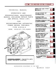
<strong>TM</strong> 3-<strong>4240</strong>-<strong>313</strong>-20&P<br />
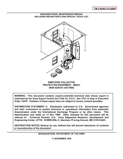
ORGANIZATIONAL MAINTENANCE MANUAL<br />
INCLUDING REPAIR PARTS AND SPECIAL TOOLS LIST<br />
<strong>SIMPLIFIED</strong> <strong>COLLECTIVE</strong><br />
<strong>PROTECTION</strong> EQUIPMENT: M20A1<br />
(NSN <strong>4240</strong>-01-330-7806)<br />
WARNING - This document contains export-controlled technical data whose export is<br />
restricted by the Army Export Control Act (Title 22, U.S.C., Sec 2751 et deq) or Executive<br />
Order 12470. Violation of these export laws are subject to severe criminal penalties.<br />
DISTRIBUTION STATEMENT C: Distribution authorized to U.S. Government agencies<br />
and their contractors to protect technical or operational information from automatic<br />
dissemination under the International Exchange Program or by other means. This<br />
detennination was made on 13 Nov 1986. Other requests for this document will be<br />
referred to: Technical Director, U.S. Army Edgewood Research, Development and<br />
Engineering Center, ATTN: SCBRD-ENL-V, Aberdeen Proving Ground, MD 21010-6423.<br />
DESTRUCTION NOTICE Destroy by any method that will prevent disclosure of contents<br />
or reconstruction of the document.<br />
HEADQUARTERS, DEPAR<strong>TM</strong>ENT OF THE ARMY<br />
17 NOVEMBER 1995
<strong>TM</strong> 3-<strong>4240</strong>-<strong>313</strong>-20&P<br />
WARNING<br />
TOXIC HAZARD<br />
Decontaminate all contaminated equipment and personnel before erecting Simplified Collective Protection Equipment<br />
(SCPE).<br />
When erecting SCPE in a toxic environment, protective mask and clothing must be worn by all personnel until SCPE is<br />
deployed and operational. The amount of protective clothing will be determined by the unit commander.<br />
When SCPE is deployed in a toxic environment, it may take up to 1-1/2 hours from time blower is turned on to purge<br />
liner of toxic vapors. Personnel who must enter SCPE during 1-1/2 hour purge time shall wear clean, uncontaminated<br />
protective clothing. Failure to do so could result in prolonged purge time and recontamination of personnel.<br />
Do not locate blower near an area where exhaust gasses are generated because filter will not remove carbon monoxide.<br />
NOISE HAZARD<br />
The blower operating noise may be hazardous to operator hearing. Hearing protection must be worn when remaining<br />
within 4 feet of blower in operation.<br />
INJURY HAZARD<br />
Three major components of SCPE weigh approximately 100 pounds each. Lifting and/or carrying can be accomplished<br />
by no fewer than two personnel.<br />
Improper lifting of PE top when erecting may cause back strain to personnel. To avoid back strain follow proper lifting<br />
procedures.<br />
Sharp edges of the filter canister can cause injury to personnel. Use care when connecting or disconnecting air ducts to<br />
filter.<br />
Keep hands clear of leg hinges when erecting or striking protective entrance (PE).<br />
Keep flame, spark, and heat clear of SCPE.<br />
FIRE HAZARD<br />
HIGH VOLTAGE<br />
High voltage exists in motor blower and recirculation filter. To prevent electrical shock ensure motor blower power switch<br />
is in off (down) position before connecting or disconnecting power cable.<br />
Disconnect power cable before performing any maintenance procedures.<br />
For first aid information, refer to FM 21-11.<br />
FIRST AID<br />
a/(b blank)
<strong>TM</strong> 3-<strong>4240</strong>-<strong>313</strong>-20&P<br />
Technical Manual<br />
No. 3-<strong>4240</strong>-<strong>313</strong>-20&P<br />
HEADQUARTERS<br />
Department of the Army<br />
Washington, D.C.,17 November 1995<br />
ORGANIZATIONAL MAINTENANCE MANUAL<br />
INCLUDING REPAIR PARTS AND SPECIAL TOOLS LIST<br />
FOR<br />
<strong>SIMPLIFIED</strong> <strong>COLLECTIVE</strong> <strong>PROTECTION</strong> EQUIPMENT: M20A1<br />
(NSN <strong>4240</strong>-01-330-7806)<br />
REPORTING ERRORS AND RECOMMENDING IMPROVEMENTS<br />
You can help improve this manual. If you find any mistakes or if you know of a way to improve<br />
the procedures, please let us know. Mail your letter or DA Form 2028 (Recommended Changes to<br />
Publications and Blank Form) direct to: Technical Director, U.S. Army Edgewood Research,<br />
Development and Engineering Center, ATTN: SCBRD-ENL-V, Aberdeen Proving Ground, MD<br />
21010-5423. A reply will be furnished to you.<br />
WARNING<br />
This document contains export-controlled technical data whose export is restricted by the Army<br />
Export Control Act (Title 22, U.S.C., Sec 2751 et seq) or Executive Order 12470. Violation of these<br />
export laws are subject to severe criminal penalties.<br />
DISTRIBUTION STATEMENT C: Distribution authorized to U.S. Government agencies and their<br />
contractors to protect technical or operational information from automatic dissemination under<br />
the International Exchange Program or by other means. This determination was made on 13 Nov<br />
86. Other requests forthis document will be referred to: Technical Director, U.S. Army<br />
Edgewood Research, Development and Engineering Center, ATTN: SCBRDENL-V, Aberdeen<br />
Proving Ground, MD 21010-5423.<br />
DESTRUCTION NOTICE Destroy by any method that will prevent disclosure of contents or<br />
reconstruction of the document.<br />
TABLE OF CONTENTS<br />
Page<br />
HOW TO USE THIS MANUAL ...............................................................................iv<br />
CHAPTER 1 INTRODUCTION ..................................................................................................1-1<br />
Section I General Information ......................................... ...................................................1-1<br />
Section II Equipment Description and Data .........................................................................1-3<br />
Section III Principles of Operation ........................................................................................1-9<br />
i
<strong>TM</strong> 3-<strong>4240</strong>-<strong>313</strong>-20&P<br />
TABLE OF CONTENTS (CONT)<br />
Page<br />
CHAPTER 2 MAINTENANCE INSTRUCTIONS .... ................................................ ..................2-1<br />
Section I<br />
Repair Parts; Tools; Special Tools; Test, Measurement and<br />
Diagnostic Equipment (<strong>TM</strong>DE); and Support Equipment ................... ..................2-1<br />
Section II Service Upon Receipt ....................................................................... ..................2-1<br />
Section III Preventive Maintenance Checks and Services (PMCS) .................... ..................2-3<br />
Section IV Troubleshooting....................................... ............................................................2-14<br />
Section V Maintenance Procedures .....................................................................................2-19<br />
Section VI Preparation for Storage and Shipment .............................................. ..................2-43<br />
APPENDIX A<br />
APPENDIX B<br />
REFERENCES ................................................................................. ..................A-1<br />
MAINTENANCE ALLOCATION CHART ........................................... ..................B-1<br />
Page<br />
Illus/<br />
Figure<br />
APPENDIX C<br />
Section I<br />
Section II<br />
REPAIR PARTS AND SPECIAL TOOLS LIST ................................. ...................C-1<br />
Introduction ..........................................................................................................C-1<br />
Repair Parts List ..................................................................................................C-1<br />
Group 00 M20A1 Simplified Collective Protection Equipment .............................................C-1-1 C-1<br />
Group 01 SCPE Room Liner Package ..................................................... ...........................C-2-1 C-2<br />
Group 02 Pressurized Protective Entrance ..................................................... ....................C-3-1 C-3<br />
0201 Protective Entrance Liner Assembly ...........................................................C-4-1 C-4<br />
020101 Dome Light..............................................................................................C-5-1 C-5<br />
Group 03 Recirculation Filter...............................................................................................C-6-1 C-6<br />
Group 04 Accessory Package..............................................................................................C-7-1 C-7<br />
0401 Short Air Duct Hose Assembly ....................................................................C-8-1 C-8<br />
040101 Straight Flange Adapter ..........................................................................C-9-1 C-9<br />
040102 Air Duct Hose Adapter ......................................................................C-9-1 C-9<br />
0402 Long Air Duct Hose Assembly ................................................. ...................C-10-1 C-10<br />
040201 Air Duct Hose Adapter ............................................................................C-10-1 C-10<br />
0403 Extension Light ........................................................................................C-11-1 C-11<br />
0404 Motor Blower Assembly ..............................................................................C-12-1 C-12<br />
ii
<strong>TM</strong> 3-<strong>4240</strong>-<strong>313</strong>-20&P<br />
TABLE OF CONTENTS (CONT)<br />
Illus/<br />
Page<br />
Figure<br />
Group 99<br />
Section III<br />
Section IV<br />
APPENDIX D<br />
APPENDIX E<br />
Bulk Items List ...................................................................................... ...........BULK-1<br />
Special Tools List (Not Applicable)<br />
National Stock Number and Part Number Index ...............................................C-I-1<br />
EXPENDABLE AND DURABLE ITEMS LIST ...................................... ...........D-1<br />
ILLUSTRATED LIST OF MANUFACTURED ITEMS .......................................E-1<br />
INDEX .................................................................................................................INDEX-1<br />
iii
HOW TO USE THIS MANUAL<br />
<strong>TM</strong> 3-<strong>4240</strong>-<strong>313</strong>-20&P<br />
The SCPE Unit Maintenance Manual including Repair Parts and Special Tools List (<strong>TM</strong> 3-<strong>4240</strong>-<strong>313</strong>-20&P) contains<br />
information needed by unit maintenance crewmembers to perform maintenance authorized to them. An alphabetic<br />
index, located at the back of the manual, provides reference by page number to all areas of the manual. An index at the<br />
beginning of chapter 2 identifies all maintenance procedures location by paragraph and page number.<br />
Procedures contained in the SCPE Operator’s Manual (T 3-<strong>4240</strong>-<strong>313</strong>-10) are not repeated in this manual. Reference is<br />
made to the Operator’s Manual at points where an operator procedure is required. For example, erecting the protective<br />
entrance for inspection.<br />
The Unit Maintenance Repair Parts and Special Tools List (RPSTL) is provided as Appendix C. The RPSTL should be<br />
used as the source for parts identification and ordering information. A complete description of the RPSTL and associated<br />
National Stock Number and Part Number indexed is provided in Appendix C, Section I.<br />
iv/(v blank)
<strong>TM</strong> 3-<strong>4240</strong>-<strong>313</strong>-20&P<br />
M20A1 Simplified Collective Protection Equipment<br />
1-0
CHAPTER 1<br />
INTRODUCTION<br />
<strong>TM</strong> 3-<strong>4240</strong>-<strong>313</strong>-20&P<br />
1-1. SCOPE.<br />
Section I. GENERAL INFORMATION<br />
a. Type of Manual. This is the unit maintenance manual for use with the M20A1 Simplified Collective<br />
Protection Equipment (SCPE).<br />
b. Equipment Name and Model Number. Simplified Collective Protection Equipment: M20A1<br />
c. Purpose of Equipment. The SCPE M20AI is an inflatable system that will convert an interior room of an<br />
existing building into a positive pressure shelter for use against chemical and biological warfare agents and radioactive<br />
particles. The M2OAl allows personnel to perform assigned missions in a contaminated environment without the<br />
encumbrance of individual protective equipment.<br />
d. Special Limitations. The M20Al SCPE should be deployed in a structurally sound building. It must not be<br />
deployed outside, where it would be subject to wind, rain, solar heat loading, or direct contact with liquid agents. The<br />
SCPE does not provide:<br />
(1) Environmental control equipment (heating and cooling); however, interfaces are provided.<br />
(2) A portable source of electrical power (electrical generator).<br />
(3) NBC detection devices.<br />
(4) Protection from nuclear radiation, however, the SCPE does provide protection against radioactive<br />
particles.<br />
(5) Protection from carbon monoxide exhaust gasses.<br />
1-2. MAINTENANCE FORMS AND RECORDS.<br />
Department of the Army forms and procedures used for equipment maintenance will be those prescribed by DA<br />
PAM 738-750, The Army Maintenance Management System (TAMMS).<br />
1-3. DESTRUCTION OF ARMY MATERIEL TO PREVENT ENEMY USE.<br />
For SCPE destruction procedures to prevent enemy use, refer to <strong>TM</strong> 43-0002-31 Destruction of Chemical<br />
Weapons and Defense Equipment to Prevent Enemy Use.<br />
1-4. PREPARATION FOR STORAGE OR SHIPMENT.<br />
Refer to page 2-43 for storage and shipment instructions.<br />
1-5. CORROSION PREVENTION AND CONTROL (CPC).<br />
a. Corrosion Prevention and Control (CPC) of Army material is a continuing concern. It is important that any<br />
corrosion problems with this item be reported so that the problem can be corrected and improvements can be made to<br />
prevent the problem in future items.<br />
b. While corrosion is typically associated with rusting of metals, it can also include deterioration of other<br />
materials such as rubber and plastic. Unusual cracking, softening, swelling, or breaking of these materials may be a<br />
corrosion problem.<br />
1-1
<strong>TM</strong> 3-<strong>4240</strong>-<strong>313</strong>-20&P<br />
1-5. CORROSION PREVENTION AND CONTROL (CPC) (CONT).<br />
c. If a corrosion problem is identified, it can be reported using Standard Form 368. Use of key words such as<br />
"corrosion", "rust," "deterioration," or "cracking" will assure that the information is identified as a CPC problem.<br />
d. The Standard Form 368 should be submitted to:<br />
Director<br />
U.S. Army Armament and Chemical Acquisition and Logistics Activity<br />
ATTN: AMSTA-AR-QAW-A/ Customer Feedback Center<br />
Rock Island, Illinois 61299-6000<br />
1-6. REPORTING EQUIPMENT IMPROVEMENT RECOMMENDATION (EIR).<br />
If your SCPE needs improvement, let us know. Send us an EIR You, the user, are the only one who can tell us<br />
what you don't like about your equipment. Let us know why you don't like the design or performance. Put it on a<br />
Standard Form 368, Quality Deficiency Report. Mail it to us at Armament and Chemical Acquisition and Logistics<br />
Activity, ATTN: AMSTA-AR-QAW-A, Rock Island, IL 61299-6000. We will send you a reply.<br />
1-7. SAFETY, CARE, AND HANDLING.<br />
General warnings and hazard information is provided following the front cover of this manual (page a). Specific<br />
warnings are provided prior to procedural steps to which they apply.<br />
1-8. NOMENCLATURE CROSS-REFERENCE LIST.<br />
Common Name<br />
Cable Adapter<br />
(110 VAC or 220 VAC)<br />
Gage<br />
M20A1 SCPE<br />
Official Nomenclature<br />
Specialized Cable Assembly<br />
Differential Pressure Gage<br />
Simplified Collective Protection Equipment: M20AI<br />
1-9. LIST OF ABBREVIATIONS.<br />
A<br />
BTU<br />
cfm<br />
cm<br />
CPC<br />
DOT<br />
DRMO<br />
ECU<br />
HSFC<br />
Hz<br />
iwg<br />
kg<br />
kw<br />
Ampere<br />
British Thermal Unit<br />
Cubic feet per minute<br />
Centimeter<br />
Corrosion Prevention and Control<br />
Department of Transportation<br />
Defense Reutilization and Marketing Office<br />
Environmental Control Unit<br />
Hermetically Sealed Filter Canister<br />
Hertz<br />
Inches of water gage<br />
Kilogram<br />
Kilowatt<br />
1-2
<strong>TM</strong> 3-<strong>4240</strong>-<strong>313</strong>-20&P<br />
1-9. LIST OF ABBREVIATIONS - Cont.<br />
m<br />
NA<br />
NBC<br />
PE<br />
VAC<br />
VDC<br />
Meter<br />
Not Applicable<br />
Nuclear, Biological, Chemical<br />
Pressurized Protective Entrance<br />
Volt Alternating Current<br />
Volt Directing Current<br />
Section II. EQUIPMENT DESCRIPTION<br />
1-10. EQUIPMENT CHARACTERISTICS, CAPABILITIES, AND FEATURES.<br />
a. Characteristics.<br />
(1) Transported by truck.<br />
(2) Operates from 110/220 VAC, 50/60 Hz power.<br />
(3) Easily maintained.<br />
b. Capabilities and Features.<br />
(1) Includes liquid agent resistant liner.<br />
(2) Provides a recirculation filter which filters and cleans air inside the shelter.<br />
(3) Has a PE that allows personnel to move from a contaminated area into the protective shelter without<br />
introducing contaminants.<br />
(4) Can be operated without HSFC when system is used for training.<br />
(5) Accessory package contains material and repair tape for restoring damaged liners, hoses, and PE to<br />
usable condition.<br />
(6) Provides adapters to interface with environmental control unit (ECU). Two types of MIL-A-52767 ECU<br />
can be interfaced:<br />
Type 1, Size C, 18,000 BTU compact vertical air conditioner or<br />
Type 2, Size C, 18,000 BTU compact horizontal air conditioner.<br />
(7) On-board spare gaskets to repair air duct hose adapter and filter adapter are stored in the accessory<br />
package.<br />
1-3
<strong>TM</strong> 3-<strong>4240</strong>-<strong>313</strong>-20&P<br />
1-11. LOCATION AND DESCRIPTION OF MAJOR COMPONENTS.<br />
The M20Al SCPE has five major components:<br />
(1) Room Liners<br />
(2) PE<br />
(3) HSFC<br />
(4) Recirculation filter<br />
(5) Accessory package with motor blower.<br />
a. Room Liners. The room liner (1) is sealed in a protective plastic bag and packed in rubber-coated-fabric<br />
liner carrier bag. Liners are made from plastic film that is resistant to toxic liquids and gasses. When a PE is attached<br />
and liner is pressurized, it provides a protective area for personnel. Room liners (1) can be attached to one another with<br />
a room adapter (2) (included in liner package) to increase protective area. Exterior loops and ties (3) on the top of the<br />
liner can be used to provide unpressurized support for the room liner (1). Each M20Al SCPE is issued with three<br />
complete room liner packages (two are on-board spares).<br />
1-4
<strong>TM</strong> 3-<strong>4240</strong>-<strong>313</strong>-20&P<br />
b. Protective Entrance (PE). Consists of a collapsible aluminum support frame (1) and a butyl-coated fabric<br />
(2) enclosure. When erected, the PE is free standing. It is triangular in shape with fabric doors (3) on each side. Each<br />
door has a window (4), slit entrance with hook-and-pile fasteners (5), and hook-and-pile operated vents (6). One side has<br />
a flange (7) that is used to connect the PE to the room liner. The flange comes with two air duct sleeves (8). The outer<br />
edge of the flange has a mating hook-and-pile fastener (9). The PE also comes with interval timer (1), two gages (11),<br />
dome light (12), and power supply (13). Two carrying handles (14) are located on the top. One cable sleeve (15) is<br />
located on the inside door (flange side).<br />
1-5
<strong>TM</strong> 3-<strong>4240</strong>-<strong>313</strong>-20&P<br />
1-11. LOCATION AND DESCRIPTION OF MAJOR COMPONENTS (CONT).<br />
c. Hermetically Sealed Filter Canister (HSFC). Contains gas and particulate filters which remove chemical<br />
and biological agents and radioactive particles. The HSFC is connected to the motor blower by the short air duct and to<br />
the SCPE liner through the PE by the long air duct (not shown). The HSFC (1) is hermetically sealed until pull-tabs (2)<br />
are removed. The HSFC remains in its shipping crate (3) for normal use.<br />
d. Recirculation Filter. The recirculation filter is a portable self-contained unit. It is used to filter any residual<br />
NBC contaminants inside a deployed SCPE liner. The cover (1) is attached to the case (2) by four link-lock fasteners (3).<br />
The case (2) houses the blower and the power switch (4). The power cord (5) plugs into the PE power supply and<br />
provides 110 VAC, 50/60 Hz to the blower. Air enters through the air inlets (6) and is forced downward through the<br />
replaceable filter element (7). Air exits through the air outlets (8).<br />
1-6
<strong>TM</strong> 3-<strong>4240</strong>-<strong>313</strong>-20&P<br />
e. Accessory Package. The accessory package contains all materials required to initiate and sustain<br />
operation of SCPE. The accessory package is compact and manportable. It is designed to support the SCPE and<br />
contains the following:<br />
(1) Repair Material. Used for extensive repairs of SCPE liners.<br />
(2) Motor Blower. Provides air flow to inflate and continually purge liners and PE of contaminants. Provides<br />
power for extension light, recirculation filter, and PE dome light through the power supply located in the PE.<br />
(3) Short Air Duct (5 ft long). Provides airflow from blower to HSFC, has adapters in both ends.<br />
(4) Tape. Used to repair damaged liner, liner carrier bag, air duct hoses, and PE fabric.<br />
(5) 220 VAC Cable Adapter. Provides capability to use power cable in 220 VAC (European type) power<br />
receptacles or with a generator.<br />
(6) 110 VAC Cable Adapter. Provides capability to use power cable in I 10 VAC power receptacles or with a<br />
generator.<br />
(7) Extension Light. Provides interior light inside liner.<br />
(8) AC Power Cable Assembly. Provides electrical link between motor blower and 110/220 VAC cable adapters.<br />
(9) Accessory Case. Durable storage and carrying case for SCPE supplies and accessories.<br />
(10) Long Air Duct (7 ft long). Provides airflow from HSFC through PE to sealed liner.<br />
(11) Gaskets. On board spares used to repair air duct hose adapter and filter adapter. Consists of six filter<br />
adapter gaskets and three air duct hose adapter gaskets.<br />
1-7
<strong>TM</strong> 3-<strong>4240</strong>-<strong>313</strong>-20&P<br />
1-12. DIFFERENCES BETWEEN MODELS.<br />
There is only one version of the M20A1 SCPE.<br />
1-13. EQUIPMENT DATA.<br />
a. Dimensions and Weights of SCPE Components.<br />
LENGTH WIDTH HEIGHT WEIGHT<br />
COMPONENT INCH CM INCH CM INCH CM LB KG<br />
PE (Packaged) 48 121.92 41 104.14 9 22.86 74 33.3<br />
Accessory Package 39 99.06 24 60.96 13 33.02 76 34.2<br />
Room Liner Package 30 76.20 24 60.96 12 33.02 37 16.65<br />
HSFC (Crated) 28 71.12 30 76.20 17 43.18 120 54.43<br />
Recirculation Filter 17 43.18 17 43.18 27 68.58 40 18.0<br />
(Packaged)<br />
b. Operating Power Requirements and Characteristics of SCPE.<br />
POWER INPUT AIRFLOW<br />
COMPONENT REQUIREMENTS VOLTAGE (CFM)<br />
Motor Blower 1654 WATTS 110 or 220 VAC 50/60 Hz 200<br />
Extension Light 100 WATTS 110 VAC NA<br />
Dome Light 14 WATTS 110 VAC NA<br />
(28 VDC)<br />
Recirculation Filter 300 WATTS 110 VAC NA<br />
1-8
<strong>TM</strong> 3-<strong>4240</strong>-<strong>313</strong>-20&P<br />
Section III. PRINCIPLES OF OPERATION<br />
1-14. SYSTEM DESCRIPTION.<br />
a. To provide NBC protection, a higher pressure must exist inside the shelter than outside the shelter. The<br />
airflow that causes the pressure must pass through the HSFC. Small leaks in the shelter will have no effect as long as<br />
pressure is maintained inside shelter.<br />
b. When the system is pressurized, almost all airflow into shelter will flow back through PE to the contaminated<br />
exterior.<br />
c. The blower inflates the shelter to a pressure of 0.6 iwg. Vents between shelter and PE are adjusted for<br />
pressure of 0.6 iwg in shelter, and vents between PE and outside are adjusted for pressure of 0.25 iwg in PE. Clean air<br />
flowing from shelter to outside through PE purges toxic vapors from PE.<br />
1-15. FUNCTIONAL DESCRIPTION OF MAJOR COMPONENTS.<br />
a. Motor Blower. The blower provides a minimum of 200 cubic feet of air per minute to the protective shelter<br />
through the HSFC. It will operate on 110/220 VAC 50/60 Hz. Blower assembly provides electrical power for extension<br />
light and PE dome light through output connector J2 to the PE power supply.<br />
b. Hermetically Sealed Filter Canister (HSFC). This filter removes toxic chemical agents, biological agents,<br />
and radioactive particles from air passing through it.<br />
c. Air Ducts. The air ducts provide airflow path for air from blower through HSFC into shelter.<br />
d. Recirculation Filter. The recirculation filter removes residual toxic agents which may be present inside the<br />
SCPE liners. The recirculation filter blower motor operates from any 115 VAC 50/60 Hz electrical source.<br />
e. Room Liner. Room liners are cylindrical in shape and are inflated with filtered air from HSFC and blower.<br />
The inflated room liners provide a place to work or rest without having to wear protective clothing.<br />
f. Protective Entrance (PE). PE allows personnel to move from contaminated area into liner without<br />
introducing contaminants into protected area.<br />
g. Differential Pressure Gages. There are two gages that read from 0 iwg to 2.0 iwg. One is mounted on liner<br />
side of PE and measures difference in pressure between inside liner and outside. Another is mounted to inside wall of<br />
PE and measures difference in pressure between inside PE and outside. The gages are used when adjusting internal<br />
pressures in shelter and PE. An adjusting tool is provided to adjust gages before operation.<br />
h. Vents. Two vents near the bottom of the two outer PE walls are used to adjust PE pressure. Two vents near<br />
the top of the liner side of PE wall are used to adjust shelter pressure. PE and shelter pressure can be regulated by<br />
adjusting these vents.<br />
i. Dome Light. There is one dome light mounted to the ceiling of the PE which operates at 28 VAC supplied<br />
by PE power supply.<br />
j. Interval Timer. A mechanical five-minute bell timer is mounted on the wall of the PE. It is used to time the<br />
purge period of personnel entering the SCPE from contaminated areas.<br />
1-9/(1-10 blank)
<strong>TM</strong> 3-<strong>4240</strong>-<strong>313</strong>-20&P<br />
CHAPTER 2<br />
UNIT MAINTENANCE<br />
Section I. REPAIR PARTS, SPECIAL TOOLS, TEST, MEASUREMENT, AND<br />
DIAGNOSTIC EQUIPMENT (<strong>TM</strong>DE), AND SUPPORT EQUIPMENT<br />
2-1. COMMON TOOLS AND EQUIPMENT.<br />
For authorized tools and equipment refer to the Modified Table of Organization and Equipment (MTOE) applicable<br />
to your unit. Common tools contained in General Mechanic's Automotive Tool Kit (GMTK), SC 5180-90N26, are used for<br />
unit maintenance.<br />
2-2. SPECIAL TOOLS, <strong>TM</strong>DE, AND SUPPORT EQUIPMENT.<br />
There are no special tools or equipment required for unit maintenance.<br />
2-3. REPAIR PARTS.<br />
Repair parts are listed and illustrated in Appendix C of this manual.<br />
2-4. SERVICE UPON RECEIPT OF MATERIAL.<br />
Section II. SERVICE UPON RECEIPT<br />
SERVICE UPON RECEIPT SCPE COMPONENTS<br />
LOCATION ITEM ACTION REMARKS<br />
1. PE Components a. Inspect for corrosion, fungus,<br />
paint damage, and deformation.<br />
b. Erect PE. <strong>TM</strong> 3-<strong>4240</strong>-<strong>313</strong>-10<br />
c. Reject PE if damage prevents<br />
it from functioning properly.<br />
2. Accessory Components a. Inspect for corrosion, fungus,<br />
Package<br />
paint damage, and deformation.<br />
b. Reject accessory package if<br />
damage prevents components<br />
from functioning properly or if<br />
components are missing.<br />
3. Room Liner Room Liners a. Inspect for fungus, tears, and rips.<br />
Package<br />
b. Reject liner package if liner<br />
wrapper has punctures or tears.<br />
2-1
<strong>TM</strong> 3-<strong>4240</strong>-<strong>313</strong>-20&P<br />
SERVICE UPON RECEIPT - SCPE COMPONENTS (CONT)<br />
LOCATION ITEM ACTION REMARKS<br />
4. HSFC Components a. Inspect HSFC, especially around<br />
seams, for cracks, dents, holes,<br />
or water damage. Pull-tabs are<br />
damaged or missing.<br />
b. Reject HSFC if dented on a seam,<br />
cracked, dented deeper than 1/4 in.,<br />
has holes, has been damaged by<br />
water, or pull-tabs are damaged or<br />
missing.<br />
5. Recirculation Components a. Inspect unit for cracks, holes, or<br />
Filter<br />
water damage.<br />
b. Reject unit if cracked, has holes,<br />
or has been damaged by water.<br />
Packaging a. Inspect filter protective foil bag<br />
for tears or punctures.<br />
b. Reject filter if protective bag is<br />
torn or punctured.<br />
2-5. CHECKING UNPACKED EQUIPMENT.<br />
a. Inspect the equipment for damage incurred during shipment. If the equipment has been damaged, report the<br />
damage on SF 364, Report of Discrepancies.<br />
b. Check the equipment against the packing slip to see if the shipment is complete. Report all discrepancies in<br />
accordance with the instructions of DA PAM 738-750 or DA PAM 738-751 as applicable.<br />
2-2
2-6. UNIT PMCS.<br />
Section III. UNIT PREVENTIVE MAINTENANCE CHECKS AND SERVICES (PMCS)<br />
<strong>TM</strong> 3-<strong>4240</strong>-<strong>313</strong>-20&P<br />
a. Purpose. The purpose of unit PMCS is to systematically and periodically inspect and service SCPE:<br />
b. Use.<br />
(1) To ensure that the equipment is ready for operation at all times.<br />
(2) To perform those PMCS procedures that are beyond the capability of the operator/crew.<br />
(3) To discover and correct defects before they result in serious damage or failure requiring timeconsuming<br />
repairs or replacement.<br />
(1) Schedule each of your units SCPE for unit PMCS every six months.<br />
(2) Use the semi-annual (every six months) schedule as a check list each time you perform the PMCS to<br />
make sure that you perform all required procedures.<br />
(3) Use the annual schedule as a check list every other time you perform PMCS.<br />
(4) Report and record all deficiencies and shortcomings, together with corrective actions taken, on DA<br />
Form 2404, Equipment Inspection and Maintenance Worksheet.<br />
c. Warnings and Cautions. Always observe the warnings and cautions appearing in your PMCS table.<br />
Warnings and cautions appear before the applicable procedures. You must observe all warnings and cautions to prevent<br />
serious injury to yourself or others and to prevent damage to your equipment.<br />
d. Table Entries. The following paragraphs describe the information presented in each column of the PMCS<br />
table.<br />
(1) Item Number Column. Numbers in this column are for reference. When completing DA Form 2404<br />
(Equipment Inspection and Maintenance Worksheet), include the item number for the check/service<br />
indicating a fault. Item numbers also appear in the order that you must do checks and services for the<br />
intervals listed.<br />
(2) Interval Column. This column tells you when you must do the procedure in the procedure column.<br />
(3) Item to Check/Service Column. This column identifies the item to be checked or serviced.<br />
(4) Procedure Column. This column gives the procedure you must do to check or service the item listed<br />
in the Item to Check/Service column to know if the equipment is ready or available for its intended<br />
mission or for operation. You must do the procedure at the time stated in the interval column.<br />
(5) No Fully Mission Capable If: Information in this column tells you what faults will keep your equipment<br />
from being capable of performing its primary mission. If you make check and service procedures that<br />
show faults listed in this column, do not operate the equipment. Follow standard operating procedures<br />
for maintaining the equipment or reporting equipment failure.<br />
e. Other Table Entries. Be sure to observe all special information and notes that appear in your table.<br />
2-3
UNIT PREVENTIVE MAINTENANCE CHECKS AND SERVICES FOR M20A1 SCPE<br />
NOTE<br />
<strong>TM</strong> 3-<strong>4240</strong>-<strong>313</strong>-20&P<br />
If the equipment must be kept in continuous operation, do only those procedures that can be<br />
done without disturbing operation. Make complete checks and services when the equipment is<br />
shut down.<br />
Item Item to Not Fully Mission<br />
No. Interval Check/Service Procedure Capable If:<br />
1 Semiannual<br />
Punctures or tears in wrapper.<br />
M20A1<br />
ROOM LINER<br />
PACKAGE<br />
a. Check carrier bags (1) for punc<br />
tures or tears. If punctures or<br />
tears are noted, remove liner<br />
(2) with protective wrapper and<br />
check wrapper for punctures or<br />
tears. If punctures or tears are<br />
noted in wrapper, replace liner<br />
and bag.<br />
b. Check carrier bag (1) to ensure<br />
it contains one liner (2) and one<br />
room adapter (3). If item is<br />
missing, obtain another M20A1<br />
room liner package.<br />
Room liner or room adapter<br />
missing.<br />
2-4
<strong>TM</strong> 3-<strong>4240</strong>-<strong>313</strong>-20&P<br />
Item Item to Not Fully Mission<br />
No. Interval Check/Service Procedure Capable If:<br />
2 Semi<br />
annual<br />
PEFRAME a. Erect PE (<strong>TM</strong> 3-<strong>4240</strong>-<strong>313</strong>-10).<br />
Check for distorted, cracked or<br />
bent frame (1). Check for<br />
broken or missing hinge pins (2)<br />
(three on each leg). Check that<br />
legs are locked and knobs (3)<br />
are present. Check for broken<br />
or missing link-lock fasteners<br />
(4). Replace PE if defective.<br />
Frame cracked or bent. Hinge<br />
pin or locking knob is missing.<br />
Legs cannot be locked.<br />
b. Check for broken or missing<br />
interval timer (5) and gages (6).<br />
Adjust gages to zero. Replace<br />
if necessary.<br />
Interval timer and/or gages<br />
broken or missing. Gages will<br />
not adjust to zero.<br />
2-5
UNIT PREVENTIVE MAINTENANCE CHECKS AND SERVICES FOR M20A1 SCPE (CONT)<br />
<strong>TM</strong> 3-<strong>4240</strong>-<strong>313</strong>-20&P<br />
Item Item to Not Fully Mission<br />
No. Interval Check/Service Procedure Capable If:<br />
3 Semiannual<br />
PE FABRIC<br />
Check for punctures, tears, broken<br />
windows (1), missing vent flaps<br />
(2), separated seams or worn<br />
hook-and-pile fasteners. Restore<br />
to usable conditions as<br />
necessary.<br />
Fabric punctured or torn,<br />
windows broken, vent flaps<br />
missing, seams separated,<br />
hook-and-pile fasteners worn.<br />
4 Semiannual<br />
PE POWER<br />
Check power supply (3) for dents or<br />
SUPPLY cracks. Inspect both<br />
power cords (4) for bare wires,<br />
cracked or split insulation or<br />
connectors or missing connector<br />
or missing connector pins (5)<br />
connector pins.<br />
Power supply dented or<br />
cracked. Power cord has bare<br />
wires, cracked or split<br />
insulation or connectors or<br />
missing connector or missing<br />
2-6
<strong>TM</strong> 3-<strong>4240</strong>-<strong>313</strong>-20&P<br />
Item Item to Not Fully Mission<br />
No. Interval Check/Service Procedure Capable If:<br />
5 Semiannual<br />
HSFC<br />
Check HSFC (1), especially around<br />
seams (2), for cracks, dents,<br />
holes, or water damage.<br />
Replace HSFC if dented on a<br />
seam, cracked, dented deeper<br />
than 1/4 in., has holes, or has<br />
been damaged by water.<br />
HSFC is dented on a seam,<br />
cracked, or dented deeper<br />
than 1/4 in., has holes, or has<br />
been damaged by water.<br />
6 Semiannual<br />
ACCESSORY<br />
PACKAGE<br />
Check for missing components.<br />
Replace components as<br />
necessary (App C).<br />
Components missing.<br />
2-7
UNIT PREVENTIVE MAINTENANCE CHECKS AND SERVICES FOR M20A1 SCPE (CONT)<br />
<strong>TM</strong> 3-<strong>4240</strong>-<strong>313</strong>-20&P<br />
Item Item to Not Fully Mission<br />
No. Interval Check/Service Procedure Capable If:<br />
7 Semiannual<br />
AIR DUCTS<br />
Check air duct hoses (1) for<br />
punctures or tears or protruding<br />
wires. Check for cracked or bent<br />
adapters (2) or missing or<br />
damaged hose clamps (3).<br />
Check for missing cracked or<br />
cut gaskets (4). Restore hoses<br />
to operating condition. Replace<br />
damaged or missing parts (para<br />
2-11).<br />
Air duct has punctured, torn or<br />
protruding wires, damaged or<br />
missing hose clamps, cracked<br />
or bent adapters or missing,<br />
cracked or cut gaskets.<br />
8 Semiannual<br />
ELECTRICAL<br />
CABLES<br />
(POWER CABLE<br />
CABLE<br />
ADAPTERS)<br />
Check cables (1) for cut or torn<br />
insulation. Check connector<br />
housing (2) for bent or missing<br />
prongs (3). Replace damaged<br />
electrical cables or adapters.<br />
Cable insulation is cut or torn,<br />
bent or missing connector<br />
prongs.<br />
2-8
<strong>TM</strong> 3-<strong>4240</strong>-<strong>313</strong>-20&P<br />
Item Item to Not Fully Mission<br />
No. Interval Check/Service Procedure Capable If:<br />
9 Semiannual<br />
MOTOR BLOWER a. Check to see if 550 hrs have<br />
elapsed on time totalizing meter<br />
(1) since last motor change. If<br />
550 hrs have elapsed, replace<br />
air filter, both blower motors,<br />
Time totalizing meter reads<br />
more than 550 hrs.<br />
gaskets, and time totalizing<br />
meter (para 2-13a).<br />
b. Check for cracked, broken, or<br />
distorted housing (2).<br />
c. Check air outlet flange (3) for<br />
damaged, bent, or missing<br />
prongs. Check for damaged<br />
outlet port or missing electronic<br />
component shield (7).<br />
d. Check for damaged electrical<br />
connectors (4). Check for<br />
damaged or missing electrical<br />
connector covers (5).<br />
e. Check for loose or missing<br />
screws (6). Tighten loose<br />
screws (6).<br />
Housing cracked, broken, or<br />
distorted.<br />
Outlet flange damaged, bent<br />
or missing prongs. Electronic<br />
component shield damaged or<br />
missing.<br />
Electrical connectors or covers<br />
are damaged or missing.<br />
Missing screws.<br />
Replace missing or damaged<br />
parts (para 2-13).<br />
2-9
UNIT PREVENTIVE MAINTENANCE CHECKS AND SERVICES FOR M20A1 SCPE (CONT)<br />
<strong>TM</strong> 3-<strong>4240</strong>-<strong>313</strong>-20&P<br />
Item Item to Not Fully Mission<br />
No. Interval Check/Service Procedure Capable If:<br />
9 Semi<br />
annual<br />
MOTOR BLOWER f. Remove access cover (1), air<br />
(CONT) filter (2), and cover<br />
plate (3) (para 2-13a). Check<br />
for damaged electronic<br />
component shield (4) or gaskets<br />
(5).<br />
Electronic components shield<br />
or gaskets damaged.<br />
10 Semiannual<br />
EXTENSION<br />
LIGHT<br />
a. Check cord (1) for cut, cracked<br />
or torn insulation. Check<br />
connector housing (2) for<br />
cracks, missing screws, bent or<br />
missing prongs.<br />
Cord insulation cracked or<br />
torn, connector cracked,<br />
missing screws, or bent or<br />
missing prongs.<br />
b. Check for cracked or missing<br />
cover (3).<br />
Cover cracked or missing.<br />
c. Plug light in to ensure light is<br />
operational.<br />
Light not operating.<br />
2-10
<strong>TM</strong> 3-<strong>4240</strong>-<strong>313</strong>-20&P<br />
Item Item To Not Fully Mission<br />
No Interval Check/Service Procedures Capable If :<br />
11 Annual PE DOME a. Replace both lamps in dome<br />
LIGHT<br />
light (para 2-9e).<br />
b. Check dome light for bent or Retainer cracked or bent, lens<br />
cracked retainer (1), cracked or cracked or broken, lamps<br />
broken lens (2), inoperative<br />
inoperative, torn or gasket.<br />
Deteriorated lamps (3), torn or<br />
deteriorated gasket (4). Replace<br />
if necessary (para 2-9).<br />
2-11
<strong>TM</strong> 3-<strong>4240</strong>-<strong>313</strong>-20&P<br />
Section IV. TROUBLESHOOTING<br />
2-7. SCOPE.<br />
a. The troubleshooting table lists common malfunctions which you may find during the operation or<br />
maintenance of the SCPE or its components. You should perform the test/inspection and corrective action in the order<br />
listed.<br />
b. This manual cannot list all malfunctions that may occur, nor all test or inspections and corrective actions. If<br />
a malfunction is not listed or is not corrected by listed corrective actions, notify your supervisor.<br />
c. Use the following symptom index to locate troubleshooting procedures.<br />
SYMPTOM INDEX<br />
Malfunction Symptom<br />
Troubleshooting<br />
Procedure<br />
Page<br />
1. PRESSURE LOW IN ROOM LINER OR PE. 2-13<br />
2. MOTOR BLOWER NOT OPERATING PROPERLY. 2-14<br />
3. LOW AIRFLOW FROM BLOWER. 2-14<br />
4. NOISY MOTOR BLOWER OPERATION. 2-15<br />
5. RECIRCULATION FILTER BLOWER NOT OPERATING PROPERLY. 2-15<br />
6. EXTENSION LIGHT NOT WORKING. 2-16<br />
7. DOME LIGHT IN PE NOT WORKING. 2-16<br />
2-12
<strong>TM</strong> 3-<strong>4240</strong>-<strong>313</strong>-20&P<br />
TROUBLESHOOTING<br />
MALFUNCTION<br />
TEST OR INSPECTION<br />
CORRECTIVE ACTION<br />
1. PRESSURE LOW IN ROOM LINER OR PE.<br />
Step 1. Check for motor blower not operating properly.<br />
See malfunction 2.<br />
Step 2. Check air ducts for damaged duct, adapters, or damaged or missing gaskets and clamps on<br />
adapters.<br />
Restore torn ducts to operational condition using tape from accessory package.<br />
Replace damaged duct.<br />
Replace damaged adapters or missing gaskets and clamps on adapters (para 2-11).<br />
Step 3. Check for no airflow from HSFC.<br />
Replace HSFC as required.<br />
Step 4. Check for proper pressure in PE.<br />
Check gage tubing for damage.<br />
Replace gage tubing if required (para 2-9).<br />
Check PE doors to ensure they close completely.<br />
Replace PE if required.<br />
Step 5. Check SCPE liners and PE for tears or punctures.<br />
Restore to operational condition using repair material and tape from accessory package.<br />
Replace liner if pressure cannot be maintained after repairing with tape.<br />
2-13
<strong>TM</strong> 3-<strong>4240</strong>-<strong>313</strong>-20&P<br />
MALFUNCTION<br />
TEST OR INSPECTION<br />
CORRECTIVE ACTION<br />
TROUBLESHOOTING (CONT)<br />
2. MOTOR BLOWER NOT OPERATING PROPERLY.<br />
WARNING<br />
High voltage exists in blower. Be sure to disconnect power cable<br />
before removing cover.<br />
Step 1. Check for proper connection of power cable and cable adapter.<br />
Replace cable and adapter as required.<br />
Step 2. Check for cracks and breaks.<br />
Replace if damaged.<br />
Step 3. Check for no or low airflow from blower.<br />
See malfunction 3.<br />
Step 4. Check for noisy blower operation.<br />
See malfunction 4.<br />
3. LOW AIRFLOW FROM MOTOR BLOWER.<br />
Step 1. Check for dirty or clogged air filter.<br />
Change air filter (para 2-13).<br />
Step 2. Check for damaged or clogged electronic component shields.<br />
Replace electronic component shields as required (para 2-13).<br />
Step 3. Check for one or both motors not electrically connected to blower.<br />
Connect both motors (para 2-13).<br />
Step 4. Check for one or both blower motors not operating.<br />
Replace air filter element, gaskets, time totalizing meter, and both motors (para 2-13).<br />
Step 5. Replace motor blower.<br />
2-14
<strong>TM</strong> 3-<strong>4240</strong>-<strong>313</strong>-20&P<br />
MALFUNCTION<br />
TEST OR INSPECTION<br />
CORRECTIVE ACTION<br />
TROUBLESHOOTING (CONT)<br />
4. NOISY MOTOR BLOWER OPERATION.<br />
Step 1. Check for loose or missing screws, nuts, bolts, or parts.<br />
Tighten loose screws, nuts, bolts. Replace missing screws, nuts, bolts, or parts.<br />
Step 2. Check for improper installation of motors.<br />
Properly install motors. Make sure inner rubber gaskets under motors are seated properly.<br />
Step 3. Replace air filter element, both motors, gaskets, and time totalizing meter (para 2-13).<br />
5. RECIRCULATION FILTER BLOWER NOT OPERATING PROPERLY.<br />
Step 1. Check for recirculation filter blower, extension light in liner, and dome light in PE all not working.<br />
Reset circuit breaker on motor blower.<br />
Step 2. Check for proper connection of power cable and cable adapter.<br />
Replace power cable and cable adapter as required.<br />
Step 3. Check for cracks and breaks.<br />
Replace if damaged.<br />
Step 4. Check for dirty or clogged filter element.<br />
Change filter element (para 2-10).<br />
Step 5. Check fan impeller blades for damage.<br />
Replace fan impeller (para 2-10).<br />
Step 6. Replace recirculation filter.<br />
2-15
<strong>TM</strong> 3-<strong>4240</strong>-<strong>313</strong>-20&P<br />
MALFUNCTION<br />
TEST OR INSPECTION<br />
CORRECTIVE ACTION<br />
TROUBLESHOOTING (CONT)<br />
6. EXTENSION LIGHT NOT WORKING.<br />
Step 1. Check for proper connection of extension light cord to PE, power cord from PE to connector on<br />
motor blower, and power cable from connector on motor blower to power source.<br />
Connect cables (<strong>TM</strong> 3-<strong>4240</strong>-<strong>313</strong>-10).<br />
Step 2. Check to see if motor blower is not operating.<br />
See malfunction 2.<br />
Step 3. Replace extension light lamp (para 2-12).<br />
Step 4. Replace extension light.<br />
7. DOME LIGHT IN PE NOT WORKING.<br />
Step 1. Check for proper connection of power cord from PE to connector on motor blower, and power cable<br />
from connector on motor blower to power source.<br />
Connect cables (<strong>TM</strong> 3-<strong>4240</strong>-<strong>313</strong>-10).<br />
Step 2. Check to see if motor blower is not operating.<br />
See malfunction 2.<br />
Step 3. Replace both incandescent lamps in dome light (para 2-9).<br />
2-16
<strong>TM</strong> 3-<strong>4240</strong>-<strong>313</strong>-20&P<br />
Section V. MAINTENANCE PROCEDURES<br />
2-8. GENERAL.<br />
The maintenance procedures in this section are to be performed by a unit maintenance technician or by the user<br />
under Unit Maintenance supervision. This section contains detailed maintenance procedures for the following<br />
component<br />
repair or replacement.<br />
PARA PROCEDURE PAGE<br />
2-9 PROTECTIVE ENTRANCE REPAIR.............................................................................. 2-18<br />
a. Differential Pressure Gage Replacement .............................................................. 2-18<br />
b. Gage Tubing Replacement ................................................................................... 2-19<br />
c. Gage Tubing Straight Pipe Adapter Replacement ................................................. 2-21<br />
d. Interval Timer, Stamped Nut, and Knob Replacement .......................................... 2-22<br />
e. Dome Light Lamp Replacement............................................................................ 2-23<br />
f. Dome Light Gasket, Lens, and Lens Retainer Replacement.................................. 2-24<br />
2-10 RECIRCULATION FILTER REPAIR............................................................................... 2-25<br />
a. Filter Element Replacement.................................................................................. 2-25<br />
b. Axial Fan Impeller and Bottom Access Cover Replacement.................................. 2-26<br />
2-11 AIR DUCT HOSE ASSEMBLY REPAIR ......................................................................... 2-27<br />
a. Air Duct Hose, Clamp, and Adapter Replacement................................................. 2-27<br />
b. Air Duct Hose Adapter Gasket Replacement......................................................... 2-28<br />
2-12 EXTENSION LIGHT LAMP REPLACEMENT ................................................................. 2-29<br />
2-13 MOTOR BLOWER REPAIR ........................................................................................... 2-30<br />
a. Air Filter, Motors, Gaskets and Time Totalizing Meter Replacement ..................... 2-30<br />
b. Electronic Components Shield Replacement......................................................... 2-39<br />
2-17
<strong>TM</strong> 3-<strong>4240</strong>-<strong>313</strong>-20&P<br />
2-9. PROTECTIVE ENTRANCE REPAIR.<br />
This task covers:<br />
a. Differential Pressure Gage Replacement. d. Interval Timer, Stamped Nut, and Knob<br />
b. Gage Tubing Replacement. Replacement.<br />
c. Gage Tubing Straight Pipe Adapter e. Dome Light Lamp Replacement.<br />
Replacement. f. Dome Light Gasket, Lens, and Lens Retainer<br />
Replacement.<br />
a. Differential Pressure Gage Replacement.<br />
INITIAL SETUP<br />
Tools<br />
General Mechanic's Automotive Tool Kit SC 5180-90-N26<br />
Materials Parts<br />
Lockwasher (3) PN MS35338-136<br />
REMOVAL<br />
1. Pull tubing (1) from straight pipe adapter (2) on<br />
side of gage (3).<br />
2. Remove three screws (4), lockwashers (5), and<br />
flat washers (6).<br />
3. Remove gage (3) and bracket (7).<br />
INSTALLATION<br />
1. Position gage (3) and bracket (7).<br />
2. Install three flat washers (6), lockwashers (5),<br />
and screws (4).<br />
3. Push tubing (1) onto straight pipe adapter (2)<br />
on side of gage (3).<br />
2-18
<strong>TM</strong> 3-<strong>4240</strong>-<strong>313</strong>-20&P<br />
b. Gage Tubing Replacement.<br />
INITIAL SETUP<br />
Tools<br />
General Mechanic's Automotive Tool Kit<br />
SC 5180-90-N26<br />
REMOVAL<br />
NOTE<br />
This procedure is used for either the interior or exterior protective entrance gage.<br />
1. Pull tubing (1) from straight pipe adapter (2) on side of gage (3).<br />
2. Pull tubing (1) from straight pipe adapter (4) on protective entrance (5).<br />
3. Obtain new piece of tubing (1) from bulk stock and cut correct length (Fig. E-3 and E-4, App E).<br />
2-19
<strong>TM</strong> 3-<strong>4240</strong>-<strong>313</strong>-20&P<br />
2-9. PROTECTIVE ENTRANCE REPAIR (CONT).<br />
INSTALLATION<br />
1. Install tubing (1) to straight pipe adapter (4) on protective entrance (5).<br />
2. Install other end of tubing (1) to straight pipe adapter (2) on side of gage (3).<br />
2-20
<strong>TM</strong> 3-<strong>4240</strong>-<strong>313</strong>-20&P<br />
c. Gage Tubing Straight Pipe Adapter Replacement.<br />
INITIAL SETUP<br />
Tools<br />
General Mechanic's Automotive Tool Kit SC 5180-90-N26<br />
Personnel Required<br />
Two<br />
Materials/Parts<br />
Locknut PN WW-P471CQQBCA<br />
REMOVAL<br />
NOTE<br />
This procedure is used for either interior or exterior gage tubing straight pipe adapter.<br />
Removal/installation of straight pipe adapter on interior PE wall requires two personnel. One<br />
inside PE and one outside.<br />
1. Pull tubing (1) from interior side of straight pipe adapter (2).<br />
2. Hold interior side of adapter (2). At exterior side remove locknut (3) and flat washer (4).<br />
3. At interior side, pull adapter (2) and flat washer (5) away from PE fabric.<br />
INSTALLATION<br />
1. Assemble flat washer (5) and straight pipe adapter (2) and insert through PE fabric and hold.<br />
2. At exterior, install flat washer (4) and locknut (3) on adapter (2). Tighten locknut (3).<br />
3. At interior side, push tubing (1) onto adapter (2).<br />
2-21
<strong>TM</strong> 3-<strong>4240</strong>-<strong>313</strong>-20&P<br />
2-9. PROTECTIVE ENTRANCE REPAIR (CONT).<br />
d. Interval Timer, Stamped Nut, and Knob Replacement.<br />
INITIAL SETUP<br />
Tools<br />
General Mechanic's Automotive Tool Kit SC 5180-90-N26<br />
REMOVAL<br />
1. Pull knob (1) off.<br />
2. Remove stamped nut (2).<br />
3. Remove faceplate (3).<br />
4. Remove and discard timer (4).<br />
INSTALLATION<br />
CAUTION<br />
Timer will not work correctly if it is<br />
improperly mounted.<br />
1. Install timer (4) with prongs lined up with holes<br />
in bracket, ensuring TOP marking is toward<br />
short side of bracket.<br />
2. Position faceplate (3) over prongs of timer<br />
ensuring "0' is on TOP position.<br />
3. Install stamped nut (2).<br />
4. Push on knob (1).<br />
2-22
<strong>TM</strong> 3-<strong>4240</strong>-<strong>313</strong>-20&P<br />
e. Dome Light Lamp Replacement.<br />
INITIAL SETUP<br />
Tools<br />
General Mechanic's Automotive Tool Kit SC 5180-90-N26<br />
REMOVAL<br />
NOTE<br />
When one lamp fails, replace both lamps.<br />
1. Remove six screws (1), retainer (2), lens (3),<br />
and gasket (4).<br />
2. Remove two lamps (5) by pushing in and<br />
turning lamps counterclockwise.<br />
INSTALLATION<br />
1. Install two lamps (5) by pushing in and turning<br />
lamps clockwise.<br />
2. Install gasket (4), lens (3), retainer (2), and six<br />
screws (1).<br />
2-23
<strong>TM</strong> 3-<strong>4240</strong>-<strong>313</strong>-20&P<br />
2-9. PROTECTIVE ENTRANCE REPAIR (CONT).<br />
f. Dome Light Gasket, Lens, and Lens Retainer Replacement.<br />
INITIAL SETUP<br />
Tools<br />
General Mechanic's Automotive Tool Kit SC 5180-90-N26<br />
REMOVAL<br />
1. Remove six screws (1), retainer (2), lens (3),<br />
and gasket (4).<br />
2. Discard defective lens retainer, lens, or gasket.<br />
INSTALLATION<br />
1. Install gasket (4), lens (3), retainer (2), and six<br />
screws (1).<br />
2-24
<strong>TM</strong> 3-<strong>4240</strong>-<strong>313</strong>-20&P<br />
2-10. RECIRCULATION FILTER REPAIR.<br />
This task covers:<br />
a. Filter Element Replacement<br />
b. Axial Fan Impeller and Bottom Access Cover Replacement.<br />
a. Filter Element Replacement.<br />
INITIAL SETUP<br />
Tools<br />
No tools required<br />
REMOVAL<br />
NOTE<br />
Change filter in recirculation filter unit<br />
after becoming wet, damaged, or<br />
contaminated. Refer to FM 3-4.<br />
1. Disconnect recirculation filter unit (1) from<br />
power source.<br />
2. Unlatch four link-lock fasteners (2) on cover<br />
(3).<br />
3. Remove cover (3) and filter element (4).<br />
INSTALLATION<br />
1. Install new filter element (4).<br />
2. Replace cover (3).<br />
3. Latch four link-lock fasteners (2).<br />
2-25
<strong>TM</strong> 3-<strong>4240</strong>-<strong>313</strong>-20&P<br />
2-10. RECIRCULATION FILTER REPAIR (CONT).<br />
b. Axial Fan Impeller and Bottom Access Cover Replacement.<br />
INITIAL SETUP<br />
Tools<br />
General Mechanic's Automotive Tool Kit SC 5180-90-N26<br />
REMOVAL<br />
1. Position recirculation filter with bottom access<br />
cover (1) facing up.<br />
2. Remove three screws (2) from bottom access<br />
cover (1).<br />
3. Remove four screws (3), four nuts (4), four<br />
lock washers (5), and four washers (6) from<br />
filter housing and remove guard (7).<br />
4. Remove three screws (8) from fan hub (10)<br />
and remove axial fan impeller (9).<br />
INSTALLATION<br />
1. Position axial fan impeller (9) on fan hub (10)<br />
and install three screws (8).<br />
2. Position bottom access cover (1) and install<br />
three screws (2).<br />
2-26
<strong>TM</strong> 3-<strong>4240</strong>-<strong>313</strong>-20&P<br />
2-11. AIR DUCT HOSE ASSEMBLY REPAIR.<br />
This task covers:<br />
a. Air Duct Hose, Clamp, and Adapter Replacement<br />
b. Air Duct Hose Adapter Gasket Replacement.<br />
a. Air Duct Hose, Clamp, and Adapter Replacement.<br />
INITIAL SETUP<br />
Tools<br />
General Mechanic's Automotive Tool Kit SC 5180-90-N26<br />
REMOVAL<br />
NOTE<br />
This procedure is used for either short<br />
or long air duct hose, clamp, and<br />
adapter replacement.<br />
1. Loosen hose clamp (1).<br />
2. Remove hose adapter (2, 3, or 4) and clamp<br />
(1) from air duct hose (5 or 6).<br />
3. Repeat steps 1 and 2 to remove all adapters.<br />
4. Discard defective hose, clamp, or adapter.<br />
INSTALLATION<br />
1. Position hose clamp (1) around long air duct<br />
hose (5) or short air duct hose (6).<br />
2. Insert long hose adapter (2), short hose<br />
adapter (HSFC end) (3), or short hose adapter<br />
(blower end) (4) into air duct hose.<br />
3. Tighten hose clamp (1).<br />
4. Repeat steps 1, 2, and 3 for all adapters.<br />
2-27
<strong>TM</strong> 3-<strong>4240</strong>-<strong>313</strong>-20&P<br />
2-11. AIR DUCT HOSE ASSEMBLY REPAIR (CONT).<br />
b. Air Duct Hose Adapter Gasket Replacement.<br />
INITIAL SETUP<br />
Tools<br />
Pocket Knife (Item 5, App D, Sect II)<br />
NOTE<br />
This procedure is used for either short or long air duct hose adapter gasket replacement.<br />
REMOVAL<br />
1. Remove old gasket (1 or 2).<br />
2. Scrape old adhesive and gasket material from adapter surface (3).<br />
INSTALLATION<br />
1. Peel away adhesive backing tape from new HSFC adapter gasket (1) or motor blower adapter gasket (2).<br />
2. Position gasket on adapter (3) with adhesive side toward hose and press firmly in place.<br />
2-28
<strong>TM</strong> 3-<strong>4240</strong>-<strong>313</strong>-20&P<br />
2-12. EXTENSION LIGHT LAMP REPLACEMENT.<br />
This task covers:<br />
Extension Light Lamp Replacement.<br />
INITIAL SETUP<br />
Tools<br />
No tools required<br />
REMOVAL<br />
WARNING<br />
Ensure light is disconnected from power source before performing maintenance procedure.<br />
Electric shock can cause serious injury or death.<br />
1. Unscrew top portion of bulb cage (1) from extension light (2).<br />
2. Remove lamp (3).<br />
INSTALLATION<br />
1. Install new lamp (3).<br />
2. Screw top portion of bulb cage (1) on extension light (2).<br />
2-29
<strong>TM</strong> 3-<strong>4240</strong>-<strong>313</strong>-20&P<br />
2-13. MOTOR BLOWER ASSEMBLY REPAIR.<br />
This task covers:<br />
a. Air Filter, Motors, Gaskets, and Time Totaling Meter Replacement.<br />
b. Electronic Components Shield Replacement.<br />
a. Air Filter, Motors, Gaskets, and Time Totsli7ing Meter Replacement.<br />
INITIAL SETUP<br />
Tools<br />
General Mechanic's Automotive Tool Kit SC 5180-90-N26<br />
REMOVAL<br />
WARNING<br />
Hazardous voltage exists in motor<br />
blower assembly. Ensure power switch<br />
is in down (off) position, then<br />
disconnect power cable from power<br />
source before performing maintenance<br />
procedures. Electrical shock can cause<br />
serious injury or death to personnel.<br />
NOTE<br />
When one motor fails, replace both<br />
motors, gaskets, air filter, and time<br />
totalizing meter.<br />
1. Access Cover.<br />
(a)<br />
Remove four screws (1), lockwashers<br />
(2), and flat washers (3) from access<br />
cover (4).<br />
(b) Remove access cover (4).<br />
2-30
<strong>TM</strong> 3-<strong>4240</strong>-<strong>313</strong>-20&P<br />
2. Air Filter.<br />
(a)<br />
Remove two screws (5), small flat washers (6) and large flat washers (7) from air filter (8) on cover<br />
plate (9).<br />
(b) Remove and discard air filter (8).<br />
2-31
<strong>TM</strong> 3-<strong>4240</strong>-<strong>313</strong>-20&P<br />
2-13. MOTOR BLOWER ASSEMBLY REPAIR (CONT).<br />
a. Air Filter, Motors, Gaskets and Time Totalizing Meter Replacement (Cont).<br />
REMOVAL (CONT).<br />
3. Cover Plate.<br />
(a) Remove six screws (10), lockwashers (11), and flat washers (12) from cover plate (9).<br />
(b)<br />
blower housing.<br />
Tilt cover plate (9) upward. While holding cover plate, disconnect two electrical connectors (13) inside<br />
2-32
<strong>TM</strong> 3-<strong>4240</strong>-<strong>313</strong>-20&P<br />
4. Motors.<br />
(a)<br />
Turn cover plate (9) upside down, place on flat work surface.<br />
(b) Remove three screws (14), lockwashers (15), and flat washers (16), from motor blower support (17).<br />
(c)<br />
Remove case grounding wire (18) from motor grounding junction terminal (19). Retain grounding wire.<br />
(d) Remove blower support (17).<br />
(e) Remove motor (21).<br />
(f) Remove motor upper gasket (20).<br />
(g) Remove lower gasket (27).<br />
(h)<br />
Repeat steps (b) thru (g) for other motor.<br />
2-33
<strong>TM</strong> 3-<strong>4240</strong>-<strong>313</strong>-20&P<br />
2-13. MOTOR BLOWER ASSEMBLY REPAIR (CONT).<br />
a. Filter, Motors, Gaskets, and Time Totalizing Meter Replacement (Cont).<br />
REMOVAL (CONT).<br />
5. Time Totalizing Meter.<br />
(a) Remove three screws (22) and flat washers (23) from time totalizing meter (24).<br />
(b) Pull out time totalizing meter (24).<br />
(c) Remove two screws (25) and lockwashers (26) from back of time totalizing meter (24).<br />
(d) Remove two wires (27).<br />
(e)<br />
Remove time totalizing meter (24) and discard.<br />
2-34
<strong>TM</strong> 3-<strong>4240</strong>-<strong>313</strong>-20&P<br />
INSTALLATION<br />
1. Time Totalizing Meter.<br />
NOTE<br />
Use screws and lockwashers supplied with new time totalizing meter.<br />
(a) Install two wires (27) and two screws (25) and lockwashers (26) to back of time totalizing meter (24).<br />
(b) Install time totalizing meter (24).<br />
(c) Install three screws (22) and flat washers (23) to time totalizing meter (24).<br />
2-35
<strong>TM</strong> 3-<strong>4240</strong>-<strong>313</strong>-20&P<br />
2-13. MOTOR BLOWER ASSEMBLY REPAIR (CONT).<br />
a. Filter, Motors, Gaskets, and Time Totalizing Meter Replacement (Cont).<br />
INSTALLATION (CONT).<br />
2. Motors.<br />
(a)<br />
Install two lower gaskets (27) in place on<br />
cover plate (9).<br />
(b) Place upper gasket (20) on motor (21).<br />
(c) Place motor (21) on lower gasket (27).<br />
NOTE<br />
When installing blower support ensure<br />
one end of case grounding wire is<br />
installed to blower support screw that<br />
is closest to motor grounding junction<br />
terminal.<br />
(d)<br />
Place blower support (17) on upper<br />
gasket (20) and aline blower support<br />
screw posts (17) with cover plate posts.<br />
NOTE<br />
Only one motor in the motor blower<br />
requires the case grounding wire.<br />
(e)<br />
Install three screws (14), lockwashers<br />
(15), flat washers (16) and one end of<br />
case grounding wire (18) to blower<br />
support (17).<br />
NOTE<br />
Ensure that green grounding motor<br />
wire and case grounding wire are<br />
installed on grounding junction<br />
terminal.<br />
(f) Install green motor grounding wire (18)<br />
to motor grounding wire terminal (19).<br />
(g)<br />
(g)<br />
Install case grounding wire (28) to rear<br />
grounding wire terminal (29).<br />
Repeat steps (b) thru (e) for other motor.<br />
2-36
<strong>TM</strong> 3-<strong>4240</strong>-<strong>313</strong>-20&P<br />
3. Cover Plate.<br />
(a)<br />
Tilt cover plate upward. While holding cover plate, connect two electrical connectors (13) inside<br />
blower housing.<br />
(b) Install cover (9), six screws (10), lockwashers (11), and flat washers (12).<br />
2-37
<strong>TM</strong> 3-<strong>4240</strong>-<strong>313</strong>-20&P<br />
2-13. MOTOR BLOWER ASSEMBLY REPAIR (CONT).<br />
a. Filter, Motors, Gaskets, and Time Totalizing Meter Replacement (Cont).<br />
INSTALLATION (CONT).<br />
4. Air Filter.<br />
(a)<br />
Place air filter (8) on top of cover plate (9) with support grid facing down.<br />
(b) Install two screws (5), small flat washers (6) and large flat washers (7) to air filter (8) on cover plate (9).<br />
5. Access Cover.<br />
(a) Install access cover (4).<br />
(b) Install four screws (1), lockwashers (2), and flat washers (3).<br />
2-38
<strong>TM</strong> 3-<strong>4240</strong>-<strong>313</strong>-20&P<br />
b. Electronic Components Shield Replacement.<br />
INITIAL SETUP<br />
Tools<br />
General Mechanic's Automotive Tool Kit SC 5180-90-N26<br />
Pocket Knife (Item 5, App D, Sect II)<br />
REMOVAL<br />
NOTE<br />
This procedure is used to replace all<br />
electronic component shielding<br />
elements. Replace shield only if<br />
damaged, restricting air flow or<br />
electrical bonding capabilities have<br />
decreased.<br />
NOTE<br />
Retain air filter to install after shield<br />
replacement.<br />
1. Remove access cover and air filter (para 2-<br />
13a, steps I and 2).<br />
2. Cover Plate Electronic Components Shield.<br />
(a)<br />
(b)<br />
Remove fourteen screws (1) from cover<br />
plate electronic components shield (2)<br />
and cover plate (3).<br />
Remove and discard damaged cover<br />
plate electronic components shield (2).<br />
2-39
<strong>TM</strong> 3-<strong>4240</strong>-<strong>313</strong>-20&P<br />
2-13. MOTOR BLOWER ASSEMBLY REPAIR (CONT).<br />
b. Electronic Components Shield Replacement (Cont).<br />
REMOVAL (CONT).<br />
3. Shielding Gaskets.<br />
(a) Remove cover plate (3) (para 2-13a, step 3).<br />
(b) Remove old gasket material from cover plate gasket grooves (4).<br />
(c) Clean adhesive material from cover plate gasket grooves (4).<br />
4. Outlet Port Electronic Components Shield.<br />
(8).<br />
(a)<br />
(b)<br />
Remove four self-locking nuts (5) lockwashers (6), and flat washers (7) at edge of outlet port electronic<br />
components shield (8).<br />
Remove four screws (9) and remove and discard damaged outlet port electronic components shield<br />
2-40
INSTALLATION<br />
<strong>TM</strong> 3-<strong>4240</strong>-<strong>313</strong>-20&P<br />
1. Outlet Port Electronic Components Shield.<br />
(a) Hold outlet port electronic components shield (8) in place on inside of blower housing with wire mesh gasket<br />
side against housing. Insert screw (9) from outside of blower housing.<br />
(b) Install flat washer (7), lockwasher (6), and self-locking nut (5) and hand tighten.<br />
(c) Repeat steps (a) and'(b) for three remaining fasteners.<br />
(d) Tighten four self-locking nuts (5).<br />
2-41
<strong>TM</strong> 3-<strong>4240</strong>-<strong>313</strong>-20&P<br />
2-13. MOTOR BLOWER ASSEMBLY REPAIR (CONT).<br />
b. Electronic Components Shield Replacement (Cont).<br />
INSTALLATION (CONT).<br />
2. Shielding Gaskets.<br />
(a) Fabricate two 12.25 in. and three 16.25 in.<br />
gaskets (Fig. E-2, Fig. E-l, App E).<br />
(b) Apply adhesive (Item 1, App D, Sect II) to cover<br />
plate gasket groove (4). Smooth with finger for a<br />
uniform coating.<br />
NOTE<br />
Gasket material should completely fill<br />
gasket grooves. Be sure that wider side of<br />
gasket is in contact with cover plate.<br />
(c) Position gaskets in cover plate gasket grooves and<br />
press firmly in place.<br />
(d) Install cover plate (3) in blower housing (para 2-<br />
13a, step 3).<br />
3. Cover Plate Electronic Components Shield.<br />
(a) Position cover plate electronic components shield<br />
(2), with wire mesh gasket side down, on cover<br />
plate. Install fourteen screws (1).<br />
(b) Tighten fourteen screws (1).<br />
4. Install air filter and access cover (para 2-13a, steps 4<br />
and 5).<br />
2-42
Section VI. PREPARATION FOR STORAGE AND SHIPMENT<br />
<strong>TM</strong> 3-<strong>4240</strong>-<strong>313</strong>-20&P<br />
2-14. SECURITY PROCEDURES<br />
The SCPE is a non-sensitive item and may be stored or shipped using standard storage and transportation<br />
handling procedures.<br />
2-15. STORAGE.<br />
The SCPE should be stored as a complete system. Only the HSFC should remain crated.<br />
2-16. PRESERVATION, PACKAGING, PACKING, MARKING, AND SHIPPING REQUIREMENTS.<br />
No special requirements exist for the SCPE. Shipment from storage to site should be made as a complete system.<br />
Only the HSFC will be shipped crated.<br />
2-43/(2-44 blank)
<strong>TM</strong> 3-<strong>4240</strong>-<strong>313</strong>-20&P<br />
APPENDIX A<br />
REFERENCES<br />
A-1. SCOPE<br />
This appendix lists all technical manuals, field manuals, DA Pamphlets, forms, and bulletins referenced in this<br />
manual.<br />
A-2. TECHNICAL MANUALS<br />
Destruction of Chemical Weapons and Defense Equipment<br />
to Prevent Enemy Use............................................................................................................ <strong>TM</strong> 43-0002-31<br />
Chemical, Toxicological and Missile Fuel<br />
Handler Protective Clothing .................................................................................................... <strong>TM</strong> 10-277<br />
Operators Manual for M20AI SCPE............................................................................................... <strong>TM</strong> 3-<strong>4240</strong>-<strong>313</strong>-10<br />
A-3. FIELD MANUALS<br />
NBC Protection ........................................................................ .................................................... FM 3-4<br />
NBC Decontamination .................................................................................................................. FM 3-5<br />
First Aid for Soldiers ..................................................................................................................... FM 21-11<br />
A-4. DA PAMPHLETS<br />
The Army Maintenance Management System (TAMMS) .............................................................. DA PAM 738-750<br />
Functional Users Manual for the Army Maintenance Management<br />
System-Aviation (TAMMS-A) ................................................................................................. DA PAM 738-751<br />
A-5. DA FORMS<br />
Recommended Changes to Equipment Technical Publications ...................................... .............. DA FORM 2028-2<br />
Equipment Inspection and Maintenance Worksheet ................................................... .................. DA FORM 2404<br />
A-6. STANDARD FORMS<br />
Quality Deficiency Report.............................................................................................................. SF 368<br />
Report of Discrepancies ................................................................................................................ SF 364<br />
A-7. OTHER<br />
Common Table of Allowances ......................................................................................................CTA 8-100/<br />
CTA 50-970<br />
A-1/(A-2 blank)
APPENDIX B<br />
<strong>TM</strong> 3-<strong>4240</strong>-<strong>313</strong>-20&P<br />
B-1. THE ARMY MAINTENANCE SYSTEM MAC.<br />
MAINTENANCE ALLOCATION CHART (MAC)<br />
Section I. INTRODUCTION<br />
a. This introduction (Section I) provides a general explanation of all maintenance and repair functions<br />
authorized at various maintenance levels under the standard Army Maintenance System concept.<br />
b. The Maintenance Allocation Chart (MAC) in Section II designates overall authority and responsibility for the<br />
performance of maintenance functions on the identified end item or component. The application of the maintenance<br />
functions to the end item or component will be consistent with the capacities and capabilities of the designated<br />
maintenance levels which are shown on the MAC in column (4) as:<br />
Unit - includes two subcolumns, C (operator/crew) and O (unit) maintenance.<br />
Direct Support - includes an F subcolumn.<br />
General Support - includes an H subcolumn.<br />
Depot - includes a D subcolumn.<br />
c. Section III lists the tools and test equipment (both special tools and common tool sets) required for each<br />
maintenance function as referenced from Section II.<br />
d. Section IV contains supplemental instructions and explanatory notes for a particular maintenance function.<br />
B-2. MAINTENANCE FUNCTIONS.<br />
Maintenance functions are limited to and defined as follows:<br />
a. Inspect. To determine the serviceability of an item by comparing its physical, mechanical, and/or electrical<br />
characteristics with established standards through examination (e.g., by sight, sound, or feel).<br />
b. Test. To verify serviceability by measuring the mechanical, pneumatic, hydraulic, or electrical characteristics<br />
of an item and comparing those characteristics with prescribed standards.<br />
c. Service. Operations required periodically to keep an item in proper operating condition; i.e., to clean (includes<br />
decontaminate, when required), to preserve, to drain, to paint, or to replenish fuel, lubricants, chemical fluids or gases.<br />
d. Adjust. To maintain or regulate, within prescribed limits, by bringing into proper or exact position, or by setting<br />
the operating characteristics to specified parameters.<br />
e. Aline. To adjust specified variable elements of an item to bring about optimum or desired performance.<br />
f. Calibrate. To determine and cause corrections to be made or to be adjusted on instruments or test, measuring,<br />
and diagnostic equipment used in precision measurement. Consists of comparisons of two instruments, one of which is a<br />
certified standard of known accuracy, to detect and adjust any discrepancy in the accuracy of the instrument being<br />
compared.<br />
B-1
B-2. MAINTENANCE FUNCTIONS (CONT).<br />
<strong>TM</strong> 3-<strong>4240</strong>-<strong>313</strong>-20&P<br />
g. Remove/Install. To remove and install the same item when required to perform service or other maintenance<br />
functions. Install may be the act of emplacing, seating, or fixing into position a spare, repair part, or module (component<br />
or assembly) in a manner to allow the proper functioning of an equipment or system.<br />
h. Replace. To remove an unserviceable item and install a serviceable counterpart in its place. "Replace" is<br />
authorized by the MAC and assigned maintenance level is shown as the 3rd position code of the SMR code.<br />
i. Repair. The application of maintenance services including fault location/troubleshooting, removal/ installation,<br />
and disassembly/assembly procedures, and maintenance actions to identify troubles and restore serviceability to an item<br />
by correcting specific damage, fault, malfunction, or failure in a part, subassembly, module (component or assembly),<br />
end item, or system.<br />
j. Overhaul. That maintenance effort (service/action) prescribed to restore an item to a completely<br />
serviceable/operational condition as required by maintenance standards in appropriate technical publications (i.e.,<br />
DMWR). Overhaul is normally the highest degree of maintenance performed by the Army. Overhaul does not normally<br />
return an item to like new condition.<br />
k. Rebuild. Consists of those services/actions necessary for the restoration of unserviceable equipment to a like<br />
new condition in accordance with original manufacturing standards. Rebuild is the highest degree of materiel<br />
maintenance applied to Army equipment. The rebuild operation includes the act of returning to zero those age<br />
measurements (e.g., hours/miles) considered in classifying Army equipment/components.<br />
B-3. EXPLANATION OF COLUMNS IN THE MAC, SECTION II.<br />
a. Column (1), Group Number. Column (1) lists functional group code numbers, the purpose of which is to<br />
identify maintenance significant components, assemblies, subassemblies, and modules with the next higher assembly.<br />
b. Column (2), Component/Assembly. Column (2) contains the item names of components, assemblies,<br />
subassemblies, and modules for which maintenance is authorized.<br />
c. Column (3), Maintenance Function. Column (3) lists the functions to be performed on the item listed in column<br />
(2).<br />
d. Column (4), Maintenance Level. Column (4) specifies each level of maintenance authorized to perform each<br />
function listed in column (3), by indicating work time required (expressed as man-hours in whole hours or decimals) in the<br />
appropriate subcolumn. This work-time figure represents the active time required to perform that maintenance function<br />
at the indicated level of maintenance. If the number or complexity of the tasks within the listed maintenance function<br />
vary at different maintenance levels, appropriate work-time figures are to be shown for each level. The work time figure<br />
represents the average time required to restore an item (assembly, subassembly, component, module, end item, or<br />
system) to a serviceable condition under typical field operating conditions. This time includes preparation time (including<br />
any necessary disassembly/assembly time), troubleshooting/fault location time, and quality assurance time in addition to<br />
the time required to perform the specific tasks identified for the maintenance functions authorized in the maintenance<br />
allocation chart. The symbol designations for the various maintenance levels are as follows:<br />
C. ..................... Operator or Crew<br />
O ..................... Unit Maintenance<br />
F ...................... Support Maintenance<br />
L ...................... Specialized Repair Activity (SRA)<br />
D .................... Depot Maintenance<br />
B-2
<strong>TM</strong> 3-<strong>4240</strong>-<strong>313</strong>-20&P<br />
e. Column (5), Tools and Test Equipment Reference Code. Column (5) specifies, by code, those common tool<br />
sets (not individual tools), common <strong>TM</strong>DE, and special tools, special <strong>TM</strong>DE, and special support equipment required to<br />
perform the designated function. Codes are keyed to tools and test equipment in Section III.<br />
f. Column (6), Remarks. When applicable, this column contains a letter code, in alphabetic order, which is keyed<br />
to the remarks contained in Section IV.<br />
B-4. EXPLANATION OF COLUMNS IN TOOL AND TEST EQUIPMENT REQUIREMENTS, SECTION III.<br />
a. Column (1), Reference Code. The tool and test equipment reference code correlates with a code used in the<br />
MAC, Section II, Column 5.<br />
b. Column (2), Maintenance Level. The lowest level of maintenance authorized to use the tool or test equipment.<br />
c. Column (3), Nomenclature. Name or identification of the tool or test equipment.<br />
d. Column (4), National Stock Number. The National stock number of the tool or test equipment.<br />
e. Column (5), Tool Number. The manufacturer's part number model number or type number.<br />
B-5. EXPLANATION OF COLUMNS IN REMARKS, SECTION IV.<br />
a. Column (1), Reference Code. The code recorded in column 6, Section II.<br />
b. Column (2), Remarks. This column lists information pertinent to the maintenance function being performed as<br />
indicated in the MAC, Section II.<br />
B-3
Section II. MAINTENANCE ALLOCATION CHART<br />
FOR<br />
M20A1 <strong>SIMPLIFIED</strong> <strong>COLLECTIVE</strong> <strong>PROTECTION</strong> EQUIPMENT<br />
<strong>TM</strong> 3-<strong>4240</strong>-<strong>313</strong>-20&P<br />
(1) (2) (3) (4) (5) (6)<br />
MAINTENANCE LEVEL<br />
DIRECT GENERAL<br />
GROUP COMPONENT/ MAINTENANCE UNIT SUPPORT SUPPORTDEPOT TOOLS AND<br />
NUMBER ASSEMBLY FUNCTION C O F H D EQUIPMENT REMARKS<br />
00 M20A1 NBC Inspect 0.2<br />
Simplified Repair 0.2<br />
Collective<br />
Protection<br />
Equipment<br />
REF CODE<br />
01 Room Simplified Inspect 0.2 0.2<br />
Collective Replace 0.2<br />
Protection Repair 0.2 0.2 A<br />
Equipment Liner<br />
Package<br />
02 Pressurized Inspect 0.2 0.2<br />
Protective Replace 0.3<br />
Entrance Repair 0.3 1 A<br />
0201 Pressurized Repair 0.1 0.2 1 A<br />
Protective<br />
Entrance Liner<br />
Assembly<br />
020101 Dome Light Inspect 0.1 0.1<br />
Repair 0.2 1<br />
03 Recirculation Inspect 0.1 0.1<br />
Filter Replace 0.1<br />
Repair 0.2 1<br />
04 Accessory Inspect 0.1 0.1<br />
Package Repair 0.1<br />
0401 Short Air Duct Inspect 0.1 0.1<br />
Hose Assembly Repair 0.1 0.2 1 A<br />
040101 Straight Flange Inspect 0.1 0.1<br />
Adapter Replace 0.1 1<br />
Repair 0.1 1<br />
040102 Air Duct Hose Inspect 0.1 0.1<br />
Adapter Replace 0.1 1<br />
Repair 0.1 1<br />
0402 Long Air Duct Inspect 0.1 0.1<br />
Hose Assembly Repair 0.1 0.2 1 A<br />
040201 Air Duct Hose Inspect 0.1 0.1<br />
Adapter Replace 0.1 1<br />
Repair 0.1 1<br />
0403 Extension Light Inspect 0.1 0.1<br />
Assembly Repair 0.1<br />
0404 Motor Blower Inspect 0.1 0.1<br />
Assembly Replace 0.1<br />
Repair 0.5 1<br />
B-4
<strong>TM</strong> 3-<strong>4240</strong>-<strong>313</strong>-20&P<br />
Section III. TOOLS AND TEST EQUIPMENT REQUIREMENTS<br />
FOR<br />
M20A1 <strong>SIMPLIFIED</strong> <strong>COLLECTIVE</strong> <strong>PROTECTION</strong> EQUIPMENT<br />
(1) (2) (3) (4) (5)<br />
TOOL OR TEST<br />
NATIONAL<br />
EQUIPMENT MAINTENANCE STOCK TOOL<br />
REF CODE LEVEL NOMENCLATURE NUMBER NUMBER<br />
1 O Tool Kit, General 5180-00-177-7033 SC5180-90-N26<br />
Mechanics, Automotive<br />
Section IV. REMARKS<br />
FOR<br />
M20A1 <strong>SIMPLIFIED</strong> <strong>COLLECTIVE</strong> <strong>PROTECTION</strong> EQUIPMENT<br />
(1) (2)<br />
REMARKS<br />
CODE<br />
REMARKS<br />
A<br />
Crew level can restore liners, pressurized protective entrance fabric, and air<br />
duct hose assemblies to operating condition by using pressure sensitive<br />
adhesive tape.<br />
B-5/(B-6 blank)
<strong>TM</strong> 3-<strong>4240</strong>-<strong>313</strong>-20&P<br />
APPENDIX C<br />
DIRECT SUPPORT MAINTENANCE<br />
REPAIR PARTS AND SPECIAL TOOLS LIST<br />
Current as of 1 December 1995<br />
SECTION I. INTRODUCTION<br />
C-1. SCOPE.<br />
This RPSTL lists and authorizes spares and repair parts; special tools; special test, measurement, and diagnostic<br />
equipment (<strong>TM</strong>DE), and other special support equipment required for performance of Unit maintenance of the M20Al<br />
Simplified Collective Protection Equipment. It authorizes the requisitioning, issue, and disposition of spares, repair parts<br />
and special tools as indicated by the source, maintenance and recoverability (SMR) codes.<br />
C-2. GENERAL.<br />
This Repair Parts and Special Tools List is divided into the following sections:<br />
a. Section II. Repair Parts List. A list of spares and repair parts authorized by this RPSTL for use in the<br />
performance of maintenance. The list also includes parts which must be removed for replacement of the authorized<br />
parts. Parts lists are composed of functional groups in ascending alphanumeric sequence, with the parts in each group<br />
listed in ascending figure and item number sequence. Bulk materials are listed by item name in FIG. BULK at the end of<br />
the Section. Repair parts kits are listed separately in their own functional group within Section II. Repair parts for<br />
reparable special tools are also listed in this section. Items listed are shown on the associated illustration.<br />
b. Section III. Special Tools List. A list of special tools, special <strong>TM</strong>DE, and other special support equipment<br />
authorized by this RPSTL (as indicated by Basis of Issue (BOI) information in the DESCRIPTION AND USABLE ON<br />
CODE (UOC) column).<br />
c. Section IV. Cross-reference Index. There are two cross-reference indexes in this RPSTL: the National Stock<br />
Number (NSN) index which lists NSNs appearing in the listings, followed by a separate list in alphanumeric sequence of<br />
all part numbers appearing in the listings. National stock numbers and part numbers are cross-referenced to each<br />
illustration figure and item number appearance. The figure and item number index lists figure and item numbers in<br />
alphanumeric sequence and cross-references NSN, CAGEC and part numbers.<br />
C-3. EXPLANATION OF COLUMNS (Sections II).<br />
a. ITEM NO. (Column (2)). Indicates the number used to identify items called out in the illustration.<br />
C-1
<strong>TM</strong> 3-<strong>4240</strong>-<strong>313</strong>-20&P<br />
C-3. EXPLANATION OF COLUMNS (Section II).<br />
b. SMR CODIE (Column (2)), The Source, Maintenance, and Recoverability (SMR) code is a 5-position code<br />
containing supply, requisitioning information, maintenance level authorization criteria, and disposition instruction, as<br />
shown in the following breakout.<br />
Source<br />
Code<br />
Maintenance<br />
Code<br />
Recoverability<br />
Code<br />
XX 1 st two<br />
XX X<br />
positions<br />
How you get an item. 3d position 4th position<br />
Who can install,<br />
replace or use<br />
the item.<br />
Who can do<br />
complete<br />
Repair (see<br />
note) on the<br />
item.<br />
Who determines<br />
disposition action<br />
on an unserviceable<br />
the item.<br />
* Complete Repair: Maintenance capacity, capability, and authority to perform all corrective maintenance tasks of the<br />
"Repair" function in a use/user environment in order to restore serviceability to a failed item.<br />
(1) Source Code. The source code tells you how you get an item needed for maintenance, repair, or overhaul of<br />
an end item/equipment. Explanations of source codes follow.<br />
Code<br />
PA<br />
PB<br />
PC**<br />
PD<br />
PE<br />
PF<br />
PG<br />
KD<br />
KF<br />
KB<br />
MO (Made at<br />
AVUM LEVEL)<br />
MF (Made at DS/<br />
AVUM level)<br />
MH (Made at GS<br />
level)<br />
ML (Made at Speci<br />
alized Repair<br />
ACT(SRA))<br />
Explanation<br />
Stocked items; use the applicable NSN to request/requisition items with these<br />
source codes. They are authorized to the category indicated by the code<br />
entered in the 3rd position of the SMR code.<br />
**NOTE: Items coded PC are subject to deterioration.<br />
Items with these codes are not to be requested/requisitioned individually. They<br />
are part of a kit which is authorized to the maintenance category indicated in<br />
the 3rd position of the SMR code. The complete kit must be requisitioned and<br />
applied.<br />
Items with these codes are not to be requested/requisitioned<br />
individually. They must be made from bulk material which is<br />
identified by the part number in the DESCRIPTION and USABLE<br />
ON CODE (UOC) column and listed in the Bulk Material group of the<br />
repair parts list in the RPSTL. If the item is authorized to you by the<br />
3rd position code of the SMR code, but the source code indicates it<br />
Activity (SRA))is made at a higher level, order the item from the higher level of<br />
MD (Made at Depot)maintenance.<br />
C-2
<strong>TM</strong> 3-<strong>4240</strong>-<strong>313</strong>-20&P<br />
AO (Assembled by org<br />
AVUM<br />
Level)<br />
AF (Assembled by<br />
DS/AVUM<br />
Level)<br />
AH (Assembled by GS<br />
Category)<br />
AL (Assembled by SRA)<br />
AD (Assembled by Depot)<br />
Items with these codes are not to be requested/requisitioned<br />
individually. The parts that make up the assembled item must be<br />
requisitioned or fabricated and assembled at the level of<br />
maintenance indicated by the source code. If the 3rd position code<br />
of the SMR code authorizes you to replace the item, but the<br />
source code indicates the items are assembled at a higher level,<br />
order the item from the higher level of maintenance.<br />
XA - - Do not requisition an "XA"-coded item. Order its next higher assembly. (Also, refer to the NOTE below.)<br />
XB - - If an "XB" item is not available from salvage, order it using the FSCM and part number given.<br />
XC - - Installation drawing, diagram, instruction sheet, field service drawing, that is identified by manufacturer's part<br />
number.<br />
XD - - Item is not stocked. Order an "XD"-coded item through normal supply channels using the FSCM and part number<br />
given, if no NSN is available.<br />
NOTE: Cannibalization or controlled exchange, when authorized, may be used as a source of supply for items<br />
with the above source codes, except for those source coded "XA" or those aircraft support items restricted by<br />
requirements of AR 750-1<br />
(2) Maintenance Code. Maintenance codes tells you the level(s) of maintenance authorized to USE and<br />
REPAIR support items. The maintenance codes are entered in the third and fourth positions of the SMR code as follows:<br />
(a) The maintenance code entered in the third position tells you the lowest maintenance level<br />
authorized to remove, replace, and use an item. The maintenance code entered in the third position<br />
will indicate authorization to the following levels of maintenance.<br />
Code<br />
Application/Explanation<br />
C - Crew or operator maintenance done within the organization or aviation unit maintenance.<br />
O - Organizational or aviation unit category can remove, replace, and use the item.<br />
F - Direct support or aviation intermediate level can remove, replace, and use the item.<br />
H - General support level can remove, replace, and use the item.<br />
L - Specialized repair activity can remove, replace, and use the item.<br />
D - Depot level can remove, replace, and use the item.<br />
(b) The maintenance code entered in the fourth position tells whether or not the item is to be<br />
repaired and identifies the lowest maintenance level with the capability to do complete repair (i.e., perform all authorized<br />
repair functions). NOTE: Some limited repair may be done on the item at a lower level of maintenance, if authorized by<br />
the Maintenance Allocation Chart (MAC) and SMR codes. This position will contain one of the following maintenance<br />
codes.<br />
Code<br />
Application/Explanation<br />
O - Organizational or (aviation unit) is the lowest level that can do complete repair of the item.<br />
C-3
<strong>TM</strong> 3-<strong>4240</strong>-<strong>313</strong>-20&P<br />
F<br />
H<br />
L<br />
D<br />
Z<br />
B<br />
-Direct support or Aviation Intermediate is the lowest level that can do complete repair of the item.<br />
-General support is the lowest level that can do complete repair of the item.<br />
-Specialized repair activity (designate the specialized repair activity) is the lowest level that can do<br />
complete repair of the item.<br />
-Depot is the lowest level that can do complete repair of the item.<br />
-Nonreparable. No repair is authorized.<br />
-No repair is authorized. (No parts or special tools are authorized for the maintenance of a "B" coded<br />
item). However, the item may by reconditioned by adjusting, lubricating, etc., at the user level.<br />
(3) Recoverability Code. Recoverability codes are assigned to items to indicate the disposition action on<br />
unserviceable items. The recoverability code is entered in the fifth position of the SMR Code as follows:<br />
Recoverability<br />
Codes<br />
Z<br />
O<br />
F<br />
H<br />
D<br />
L<br />
A<br />
Application/Explanation<br />
-Nonreparable item. When unserviceable, condemn and dispose of the item at the level of maintenance<br />
shown in 3d position of SMR Code.<br />
-Reparable item. When uneconomically reparable, condemn and dispose of the item at Unit or Aviation<br />
Unit level.<br />
-Reparable item. When uneconomically reparable, condemn and dispose of the item at the Direct<br />
support or Aviation Intermediate level.<br />
-Reparable item. When uneconomically reparable, condemn and dispose of the item at the General<br />
support level.<br />
-Reparable item. When beyond lower level repair capability, return to depot. Condemnation and disposal<br />
of item not authorized below Depot level.<br />
-Reparable item. Condemnation and disposal not authorized below Specialized Repair Activity (S RA).<br />
-Item requires special handling or condemnation procedures because of specific reasons (e.g., precious<br />
metal content, high dollar value, critical material, or manuals/directives for specific instructions.<br />
c. CAGEC (Column (3)). The Commercial and Government Entity Code (CAGEC) is a 5-digit numeric code<br />
which is used to identify the manufacturer, distributor, or Government agency, etc., that supplies the item.<br />
d. PART NUMBER (Column (4)). Indicates the primary number used by the manufacturer (individual, company,<br />
irm, corporation, or Government activity), which controls the design and characteristics of the item by means of its<br />
engineering drawings, specifications standards, and inspection requirements to identify an item or range of items.<br />
NOTE: When you use a NSN to requisition an item, the item you receive may have a different part number from<br />
the part ordered.<br />
C-4
<strong>TM</strong> 3-<strong>4240</strong>-<strong>313</strong>-20&P<br />
e. DESCRIPTION AND USABLE ON CODE (UOC) (Column (5)). This column includes the following<br />
information:<br />
(1) The Federal item name and, when required, a minimum description to identify the item.<br />
(2) Part numbers for bulk materials are referenced in this column in the line item entry for the item to be<br />
manufactured/fabricated.<br />
(3) The statement "END OF FIGURE" appears just below the last item description in Column 5 for a given figure in<br />
both Section II and Section III.<br />
(4) Items that are included in kits and sets are listed below the name of the kit or set.<br />
f. QTY (Column (6)). The QTY (quantity per figure column) indicates the quantity of the item used in the<br />
breakout shown on the illustration figure, which is prepared for a functional group, subfunctional group, or an assembly.<br />
A "V" appearing in this column in lieu of a quantity indicates that the quantity is variable and the quantity may vary from<br />
application to application.<br />
C-4. EXPLANATION OF COLUMNS (Section IV).<br />
a. NATIONAL STOCK NUMBER (NSN) INDEX.<br />
(1) STOCK NUMBER column. This column lists the NSN by National Item Identification Number (NIIN)<br />
sequence. The NIIN consists of the last nine digits of the NSN. When using this column to locate an item, ignore the<br />
first 4 digits of the NSN. However, the complete NSN should be used when ordering items by stock number. Refer to<br />
the following example:<br />
NSN<br />
5305-01-674-1467<br />
NIIN<br />
(2) FIG. column. This column lists the number of the figure where the item is identified/located. The<br />
figures are in numerical order in Section II and III.<br />
(3) ITEM column. The item number identifies the item associated with the figure listed in the adjacent FIG.<br />
column. This item is also identified by the NSN listed on the same line.<br />
b. PART NUMBER INDEX. Part numbers in this index are listed by part number in ascending alphanumeric<br />
sequence (i.e., vertical arrangement of letter and number combination which places the first letter or digit of each group<br />
in order A through Z, followed by the numbers 0 through 9 and each following letter or digit in like order).<br />
(1) CAGEC column. The Commercial and Government Entity Code (CAGEC) is a 5-digit numeric code<br />
used to identify the manufacturer, distributor, or Government agency, etc., that supplies the item.<br />
(2) PART NUMBER column. Indicates the primary number used by the manufacturer (individual, firm,<br />
corporation, or Government activity), which controls the design and characteristics of the item by means of its<br />
engineering drawings, specifications standards, and inspection requirements to identify an item or range of items.<br />
(3) S TOCK NUMBER column. This column lists the NSN for the associated part number and manufacturer<br />
identified in the PART NUMBER and CAGEC columns to the left.<br />
II and III.<br />
(4) FIG. column. This column lists the number of the figure where the item is identified/located in Section<br />
C-5
<strong>TM</strong> 3-<strong>4240</strong>-<strong>313</strong>-20&P<br />
(5) ITEM column. The item number is that number assigned to the item as it appears in the figure<br />
referenced in the adjacent figure number column.<br />
c. FIGURE AND ITEM NUMBER INDEX.<br />
and III.<br />
(1) FIG. column. This column lists the number of the figure where the item is identified/located in Section II<br />
(2) ITEM column. The item number is that number assigned to the item as it appears in the figure<br />
referenced in the adjacent figure number column.<br />
(3) STOCK NUMBER column. This column lists the NSN for the item.<br />
(4) CAGEC column. The Commercial and Government Entity Code (CAGEC) is a 5-digit numeric<br />
code used to identify the manufacturer, distributor, or Government agency, etc., that supplies the item.<br />
(5) PART NUMBER column. Indicates the primary number used by the manufacturer (individual, firm,<br />
corporation, or Government activity), which controls the design and characteristics of the item by means of its<br />
engineering drawings, specification standards, and inspection requirements to identify an item or range of items.<br />
C-5. SPECIAL INFORMATION.<br />
a. FABRICATION INSTRUCTIONS. Bulk materials required to manufacture items are listed in the Bulk<br />
Material Functional Group of this RPSTL. Part numbers for bulk materials are also referenced in the description column<br />
of the line item entry for item to be manufactured/fabricated. Detailed fabrication instructions for items source coded to<br />
be manufactured or fabricated are found in <strong>TM</strong> 3-<strong>4240</strong>-<strong>313</strong>-20&P.<br />
b. ASSEMBLY INSTRUCTION. Detailed assembly instructions for items source coded to be assembled from<br />
component spare/repair parts are found in <strong>TM</strong> 3-<strong>4240</strong>-<strong>313</strong>-20&P. Items that make up the assembly are listed<br />
immediately following the assembly item entry or reference is made to an applicable figure.<br />
C-6. HOW TO LOCATE REPAIR PARTS.<br />
a. When National Stock Number or Part Number is Not Known.<br />
(1) First. Using the table of contents, determine the functional group or subfunctional group to which the<br />
item belongs. This is necessary since figures are prepared for functional groups and subfunctional groups, and listings<br />
are divided into the same groups.<br />
(2) Second. Find the figure covering the functional group or subfunctional group to which the item belongs.<br />
(3) Third. Identify the item on the figure and use the Figure and Item Number Index to find the NSN.<br />
b. When National Stock Number or Part Number is Known.<br />
(1) First. Using the National Stock Number or the Part Number Index, find the pertinent National Stock<br />
Number or Part Number. The NSN index is in National Item Identification Number (NIIN) sequence (see 4.a). The part<br />
numbers in the Part Number Index are listed in ascending alphanumeric sequence (see 4.b). Both indexes crossreference<br />
you to the illustration/figure and item number of the item you are looking for.<br />
(2) Second. Turn to the figure and item number, verify that the item is the one you're looking for, then<br />
locate the item number in the repair parts list for the figure.<br />
C-6
C-7. ABBREVIATIONS.<br />
<strong>TM</strong> 3-<strong>4240</strong>-<strong>313</strong>-20&P<br />
Abbreviation<br />
Explanation<br />
P. E. Protective Entrance<br />
C-7
<strong>TM</strong> 3-<strong>4240</strong>-<strong>313</strong>-20&P<br />
Section II. REPAIR PARTS LIST<br />
Figure C-1. M20A1 Simplified Collective Protection Equipment
SECTION II<br />
<strong>TM</strong> 3-<strong>4240</strong>-<strong>313</strong>-20&P<br />
(1) (2) (3) (4) (5) (6)<br />
ITEM SMR PART<br />
NO CODE CAGEC NUMBER DESCRIPTION AND USABLE ON CODES (UOC) QTY<br />
GROUP 00: M20A1 NBC <strong>SIMPLIFIED</strong><br />
<strong>COLLECTIVE</strong> <strong>PROTECTION</strong> EQUIPMENT<br />
FIG. C-1. M20A1 NBC <strong>SIMPLIFIED</strong><br />
<strong>COLLECTIVE</strong> <strong>PROTECTION</strong> EQUIPMENT<br />
5-19-11320<br />
I PACOO 81361 5-19-11334 LINER PACKAGE, SIMPL (SEE FIG. C-2 FOR ..........1<br />
BREAKDOWN)<br />
2 PAOOO 81361 5-19-11021 ENTRANCE, PROTECTIVE (SEE FIG. C-3 FOR ..........1<br />
BREAKDOWN)<br />
3 AOOOO 81361 5-19-11190 ACCESSORY PACKAGE (SEE FIG. C-7 FOR ..........1<br />
BREAKDOWN)<br />
4 PAOOO 81361 5-19-10878 FILTER, RECIRCULATIO (SEE FIGURE C-6 FOR ..........1<br />
BREAKDOWN)<br />
5 PAOZA 81361 5-19-6868 FILTER, GAS-PARTICUL ..........1<br />
END OF FIGURE<br />
C-1-1
Section II<br />
<strong>TM</strong> 3-<strong>4240</strong>-<strong>313</strong>-20&P<br />
Figure C-2. Room Simplified Collective Protection Equipment Liner Package
SECTION II<br />
<strong>TM</strong> 3-<strong>4240</strong>-<strong>313</strong>-20&P<br />
(1) (2) (3) (4) (5) (6)<br />
ITEM SMR PART<br />
NO CODE CAGEC NUMBER DESCRIPTION AND USABLE ON CODES (UOC) QTY<br />
GROUP 01: ROOM <strong>SIMPLIFIED</strong><br />
<strong>COLLECTIVE</strong> <strong>PROTECTION</strong> EQUIPMENT<br />
LINER PACKAGE<br />
FIG. C-2. ROOM <strong>SIMPLIFIED</strong><br />
<strong>COLLECTIVE</strong> <strong>PROTECTION</strong> EQUIPMENT<br />
LINER PACKAGE<br />
5-19-11334<br />
1 XAOZZ 81361 5-19-11210 LINER, ROOM, NBC ................................................................1<br />
2 PAOZZ 81361 5-19-11341 AIRLOCK ADAPTER ASS ........................................................1<br />
3 PAOZZ 81361 5-19-11062-40 BAG, CARRIER, CHEMICAL ....................................................1<br />
END OF FIGURE<br />
C-2-1
Section II<br />
<strong>TM</strong> 3-<strong>4240</strong>-<strong>313</strong>-20&P<br />
Figure C-3. Pressurized Protective Entrance
SECTION II<br />
<strong>TM</strong> 3-<strong>4240</strong>-<strong>313</strong>-20&P<br />
(1) (2) (3) (4) (5) (6)<br />
ITEM SMR PART<br />
NO CODE CAGEC NUMBER DESCRIPTION AND USABLE ON CODES (UOC) QTY<br />
GROUP 02: PRESSURIZED<br />
PROTECTIVE ENTRANCE<br />
FIG. C-3. PRESSURIZED<br />
PROTECTIVE ENTRANCE<br />
5-19-11021<br />
1 XAOOO 81361 5-19-11022 LINER ASSEMBLY (SEE FIG. C-4 FOR BREAKDOWN) .....<br />
END OF FIGURE<br />
C-3-1
Section II<br />
<strong>TM</strong> 3-<strong>4240</strong>-<strong>313</strong>-20&P<br />
Figure C-4. Protective Entrance Liner Package
SECTION II<br />
<strong>TM</strong> 3-<strong>4240</strong>-<strong>313</strong>-20&P<br />
(1) (2) (3) (4) (5) (6)<br />
ITEM SMR PART<br />
NO CODE CAGEC NUMBER DESCRIPTION AND USABLE ON CODES (UOC) QTY<br />
GROUP 0201: PRESSURIZED<br />
PROTECTIVE ENTRANCE LINER PACKAGE<br />
FIG. C-4. PRESSURIZED<br />
PROTECTIVE ENTRANCE LINER PACKAGE<br />
5-19-11022<br />
1 PAOOO 96906 MS25358-8 LIGHT, DOME ...............................................................<br />
2 PAOZZ 81348 W-L-00111/12 LAMP, INCANDESCENT ............................................... 2<br />
3 PAOZZ 96906 MS51957-30 SCREW, MACHINE ....................................................... 6<br />
4 PAOZZ 96906 MS35338-136 WASHER, LOCK ........................................................... 6<br />
5 PAOZZ 96906 MS15795-806 WASHER, FLAT ............................................................ 6<br />
6 XDOZZ 81361 5-19-8021 BRACKET ..................................................................... 2<br />
7 PBOZZ 81361 5-19-8237 GAGE, DIFFERENTIAL ................................................. 2<br />
8 MOOZZ 81361 NPN 1 TUBING, MAKE FROM TUBING, PN LT 790 ................. 2<br />
9 PAOZZ 85274 A339 ADAPTER, STRAIGHT PI .............................................. 2<br />
10 PAOZZ 96906 MS15795-815 WASHER, FLAT ............................................................ 4<br />
11 PAOZZ 81348 WW-P-471 CQQ LOCKNUT ..................................................................... 2<br />
BCA<br />
12 PAOZZ 81361 5-19-8038 TIMER, INTERVAL.........................................................<br />
13 PAOZZ 79919 K35B1 KNOB ............................................................................<br />
14 PAOZZ 79919 Z113A NUT, STAMPED ............................................................<br />
15 XDOZZ 79919 D549 FACE PLATE ................................................................<br />
16 XAOZZ 81361 NPN 3 P.E.LINER SOFTGOODS ..............................................<br />
END OF FIGURE<br />
C-4-1
Section II<br />
<strong>TM</strong> 3-<strong>4240</strong>-<strong>313</strong>-20&P<br />
Figure C-5. Dome Light
SECTION II<br />
<strong>TM</strong> 3-<strong>4240</strong>-<strong>313</strong>-20&P<br />
(1) (2) (3) (4) (5) (6)<br />
ITEM SMR PART<br />
NO CODE CAGEC NUMBER DESCRIPTION AND USABLE ON CODES (UOC) QTY<br />
GROUP 020101: DOME LIGHT<br />
FIG. C-5. DOME LIGHT<br />
MS25358-8<br />
1 XAOZZ 81361 NPN HOUSING, LIGHT....................................................... 1<br />
2 PAOZZ 96906 MS25358-6 GASKET ................................................. ................. 1<br />
3 PAOZZ 96906 MS25358-4 LENS, LIGHT ............................................................. 1<br />
4 PAOZZ 96906 MS25358-5 RETAINER, LENS ...................................................... 6<br />
5 PAOZZ 96906 MS35206-215 SCREW, MACHINE ................................................... 6<br />
END OF FIGURE<br />
C-5-1
Section II<br />
<strong>TM</strong> 3-<strong>4240</strong>-<strong>313</strong>-20&P<br />
Figure C-6. Recirculation Filter
SECTION II<br />
<strong>TM</strong>3-<strong>4240</strong>-<strong>313</strong>-20&P<br />
(1) (2) (3) (4) (5) (6)<br />
ITEM SMR PART<br />
NO CODE CAGEC NUMBER DESCRIPTION AND USABLE ON CODES(UOC) QTY<br />
GROUP 03: RECIRCULATION FILTER<br />
FIG. C-6. RECIRCULATION FILTER<br />
5-19-10878<br />
1 XDOZZ 81361 5-19-11412 COVER, ACCESS, TOP ....................................................... 1<br />
2 PAOZZ 81361 5-19-11232 FILTER, ELEMENT, GAS .................................................... 1<br />
3 XAOZZ 81361 NPN 4 HOUSING AND BLOWER .................................................... 4<br />
4 PAOZZ 96906 MS51957-46 SCREW, MACHINE ............................................................. 4<br />
5 PAOZZ 96906 MS15795-845 WASHER, FLAT .................................................................. 4<br />
6 PAOZZ 96906 MS35338-137 WASHER, LOCK ................................................................. 4<br />
7 PAOZZ 96906 MS35649-284 NUT, PLAIN, HEXAGON ..................................................... 4<br />
8 PAOZZ 81361 5-19-11607 GUARD, FAN IMPELLER .................................................... 1<br />
9 PBOZZ 81361 5-19-10885 COVER, ACCESS, BOTTOM ..... ......................................... 1<br />
10 PAOZZ 96906 MS51957-62 SCREW, MACHINE ............................................................. 3<br />
11 XDOZZ 98437 SS330-2 SCREW, MACHINE ............................................................. 3<br />
12 PAOZZ 63562 N-1233-4 IMPELLER, FAN, AXIAL....................................................... 1<br />
END OF FIGURE<br />
C-6-1
Section II<br />
<strong>TM</strong> 3-<strong>4240</strong>-<strong>313</strong>-20&P<br />
Figure C-7. Accessory Package
SECTION II<br />
<strong>TM</strong>3-<strong>4240</strong>-<strong>313</strong>-20&P<br />
(1) (2) (3) (4) (5) (6)<br />
ITEM SMR PART<br />
NO CODE FSCM NUMBER DESCRIPTION AND USABLE ON CODES(UOC) QTY<br />
GROUP 04: ACCESSORY PACKAGE<br />
FIG. C-7. ACCESSORY PACKAGE<br />
5-19-11190<br />
1 PBOOO 81361 5-19-10872 MOTOR BLOWER ASSEMB (SEE FIG. C-12 FOR ............. 1I<br />
BREAKDOWN)<br />
2 PAOZZ 81361 5-19-11399 ACCESSORY CASE, CBE ................................................... 1<br />
3 AOOOO 81361 5-19-11443 HOSE ASSEMBLY, AIR DUCT (SEE FIG. C-8 FOR ........... 1<br />
BREAKDOWN)<br />
4 PBOZZ 81361 5-19-10928 CABLE ASSEMBLY, SPEC (220 VAC) ................................ 1<br />
5 PCOZZ 81361 5-19-8144 GASKET .............................................................................. 6<br />
5A PCOZZ 81361 5-19-8092 GASKET .............................................................................. 3<br />
6 PCCZZ 86984 PPP-T-60 TY4 TAPE, PRESSURE SENSI .................................................. 1<br />
CLI<br />
7 PAOZZ 81361 5-19-11349 FABRIC, CB PROTECTIO ................................................... 1<br />
8 PBOZZ 81361 5-19-10927 CABLE ASSEMBLY, SPEC(110 VAC) ................................. 1<br />
9 AOOOO 81361 5-19-8158 LIGHT ASSEMBLY, EXTENSION (SEE FIG. C-11 .............. 1<br />
FOR BREAKDOWN)<br />
10 PAOZZ 81361 5-19-10925 CABLE ASSEMBLY, POWE ................................................ 1<br />
11 AOOOO 81361 5-19-11444 HOSE ASSEMBLY, AIR DUCT (SEE FIG. C-10 ................. 1<br />
FOR BREAKDOWN)<br />
END OF FIGURE<br />
C-7-1
Section II<br />
<strong>TM</strong> 3-<strong>4240</strong>-<strong>313</strong>-20&P<br />
Figure C-8 Short Air Duct Hose Assembly
SECTION II<br />
<strong>TM</strong>3-<strong>4240</strong>-<strong>313</strong>-20&P<br />
(1) (2) (3) (4) (5) (6)<br />
ITEM SMR PART<br />
NO CODE FSCM NUMBER DESCRIPTION AND USABLE ON CODES(UOC) QTY<br />
GROUP 0401: SHORT AIR<br />
DUCT HOSE ASSEMBLY<br />
FIG. C-8. SHORT AIR<br />
DUCT HOSE ASSEMBLY<br />
5-19-11443<br />
1 PBOZZ 81361 5-19-8051 ADAPTER, STRAIGHT, FL .................................................. 1<br />
2 PAOZZ 96906 MS35842-15 CLAMP, HOSE ...... .............................................................. 2<br />
3 PAOZZ 81361 5-19-11093-1 HOSE, AIR DUCT ................................................................ 1<br />
4 PBOZZ 81361 5-19-8139-110 ADAPTER, HOSE, AIR DU .................................................. 1<br />
END OF FIGURE<br />
C-8-1
Section II<br />
<strong>TM</strong> 3-<strong>4240</strong>-<strong>313</strong>-20&P<br />
Figure C-9. Air Duct Hose Adapters
SECTION II<br />
<strong>TM</strong>3-<strong>4240</strong>-<strong>313</strong>-20&P<br />
(1) (2) (3) (4) (5) (6)<br />
ITEM SMR PART<br />
NO CODE FSCM NUMBER DESCRIPTION AND USABLE ON CODES(UOC) QTY<br />
GROUP 040101 AND 040102:<br />
STRAIGHT FLANGE ADAPTER; AND;<br />
AIR DUCT HOSE ADAPTER<br />
FIG. C-9. STRAIGHT FLANGE ADAPTER;<br />
AND; AIR DUCT HOSE ADAPTER<br />
5-19-8051 AND 5-19-8139-110<br />
1 XAOZZ 81361 NPN 2 ADAPTER, END-PIECE ....................................................... 1<br />
2 PCOZZ 81361 5-19-8092 GASKET .............................................................................. 1<br />
3 XAOZZ 81361 NPN 10 ADAPTER, END-PIECE ....................................................... 1<br />
4 PCOZZ 81361 5-19-8144 GASKET .............................................................................. 1<br />
END OF FIGURE<br />
C-9-1
Section II<br />
<strong>TM</strong> 3-<strong>4240</strong>-<strong>313</strong>-20&P<br />
Figure C-10. Long Air Duct Hose Assembly, and Air Duct Hose Adapter
SECTION II<br />
<strong>TM</strong>3-<strong>4240</strong>-<strong>313</strong>-20&P<br />
(1) (2) (3) (4) (5) (6)<br />
ITEM SMR PART<br />
NO CODE FSCM NUMBER DESCRIPTION AND USABLE ON CODES(UOC) QTY<br />
GROUP 0402 AND 040201: LONG<br />
AIR DUCT HOSE ASSEMBLY; AND;<br />
AIR DUCT HOSE ADAPTER<br />
FIG. C-10. LONG AIR DUCT<br />
HOSE ASSEMBLY; AND; AIR<br />
DUCT HOSE ADAPTER<br />
5-19-11444 AND 5-19-8139-100<br />
1 PBOOO 81361 5-19-8139-100 ADAPTER, HOSE, AIRDU ................................................... 1<br />
2 PCOZZ 81361 5-19-8144 .GASKET.............................................................................. 1<br />
3 XAOZZ 81361 NPN 12 ADAPTER, END-PIECE........................................................ 1<br />
4 PAOZZ 96906 MS35842-15 CLAMP, HOSE ................................................................... 1<br />
5 PAOZZ 81361 5-19-11093-2 HOSE, AIR DUCT ................................................................ 1<br />
END OF FIGURE<br />
C-10-1
Section II<br />
<strong>TM</strong> 3-<strong>4240</strong>-<strong>313</strong>-20&P<br />
Figure C-11. Extension Light
SECTION II<br />
<strong>TM</strong>3-<strong>4240</strong>-<strong>313</strong>-20&P<br />
(1) (2) (3) (4) (5) (6)<br />
ITEM SMR PART<br />
NO CODE FSCM NUMBER DESCRIPTION AND USABLE ON CODES(UOC) QTY<br />
GROUP 0403: EXTENSION LIGHT ASSEMBLY<br />
FIG. C-11. EXTENSION LIGHT ASSEMBLY<br />
5-19-8158<br />
1 PAOZZ 79409 118A163 LIGHT, EXTENSION ............................................................ 1<br />
2 PAOZZ 81348 WL101-77T LAMP, INCANDESCENT ..................................................... 1<br />
END OF FIGURE<br />
C-11-1
Section II<br />
<strong>TM</strong> 3-<strong>4240</strong>-<strong>313</strong>-20&P<br />
Figure C-12. Motor Blower Assembly
SECTION II<br />
<strong>TM</strong>3-<strong>4240</strong>-<strong>313</strong>-20&P<br />
(1) (2) (3) (4) (5) (6)<br />
ITEM SMR PART<br />
NO CODE FSCM NUMBER DESCRIPTION AND USABLE ON CODES(UOC) QTY<br />
GROUP 0404: MOTOR BLOWER ASSEMBLY<br />
FIG. C-12. MOTOR BLOWER ASSEMBLY<br />
5-19-10872<br />
1 PBOZZ 81361 5-19-10876 COVER, ACCESS ............................................................... 1<br />
2 KFOZZ 81361 5-19-8258 AIR FILTER ......................................................................... 1<br />
3 PAOZZ 96906 MS24693-C76 SCREW, MACHINE.............................................................. 20<br />
4 PAOZZ 96906 MS35338-138 WASHER, LOCK ................................................................. 16<br />
5 PAOZZ 96906 MS15765-842 WASHER, FLAT .................................................................. 16<br />
6 MOOZZ 81361 5-19-10951-2 GASKET, 12.25 IN MAKE FROM GASKET .......................... 2<br />
MATERIAL, CONDUCTIVE, PN 8812247<br />
7 PAOZZ 96906 MS17830-3C NUT, SELF-LOCKING, HE .................................................. 4<br />
8 KFOZZ 81349 M3971/2-5 METER, TIME ..................................................................... 1<br />
9 PAOZZ 96906 MS51957-17 SCREW, MACHINE ............................................................. 3<br />
10 PAOZZ 96906 MS15795-803 WASHER, FLAT .................................................................. 3<br />
11 XAOZZ 81361 NPN 5 HOUSING, MOTOR BLOWE................................................ 1<br />
12 PBOZZ 81361 5-19-10898 SHIELD, ELECTRONIC C.......................................................... 4<br />
13 PAOZZ 96906 MS51957-68 SCREW, MACHINE ............................................................. 4<br />
14 PAOZZ 96906 MS51957-67 SCREW, MACHINE ............................................................. 6<br />
15 XDOZZ 81361 5-19-10937 BLOWER SUPPORT ........................................................... 2<br />
16 KFOZZ 81361 5-19-10895 GASKET .............................................................................. 4<br />
17 KFOZZ 81361 5-19-10873 MOTOR BLOWER ............................................................... 2<br />
18 MOOZZ 81361 5-19-10951-1 GASKET, 16.25 IN MAKE FROM GASKET .......................... 3<br />
MATERIAL, CONDUCTIVE, PN 8812247<br />
19 XAOZZ 81361 5-19-10890 COVER, PLATE ASSY ......................................................... 1<br />
20 XDOZZ 7K368 J-11729-190 MOUNT, SANDWICH .......................................................... 4<br />
21 PBOZZ 81361 5-19-10899 PANEL, RADIO FREQUEN ................................................. 1<br />
22 PAOZZ 96906 MS27183-41 WASHER, FLAT .................................................................. 2<br />
23 PAOZZ 96906 MS27183-13 WASHER, FLAT .................................................................. 2<br />
24 PAOZZ 96906 MS51957-62 SCREW, MACHINE ............................................................. 2<br />
25 PAOZZ 96906 MS15795-814 WASHER, LOCK ................................................................. 4<br />
26 PAOZZ 96906 MS35338-141 SCREW, MACHINE ............................................................. 4<br />
27 PAOZZ 96906 MS51957-107 SCREW, MACHINE ............................................................. 4<br />
PAOZZ 81361 5-19-10950 MAINTENANCE KIT, CBR.................................................... 1<br />
AIR FILTER<br />
(I) C-11-2<br />
GASKET<br />
(4) C-11-16<br />
MOTOR BLOWER (2) C- 11-17<br />
METER, TIME TOTALIZI (1) C-11-8<br />
END OF FIGURE<br />
C-12-1
SECTION II<br />
<strong>TM</strong>3-<strong>4240</strong>-<strong>313</strong>-20&P<br />
(1) (2) (3) (4) (5) (6)<br />
ITEM SMR PART<br />
NO CODE FSCM NUMBER DESCRIPTION AND USABLE ON CODES(UOC) QTY<br />
GROUP 99: BULK ITEMS LIST<br />
FIG. BULK<br />
1 PBOZZ 07700 8812247 GASKET MATERIAL, CON .................................................. 1<br />
2 PBOZZ 81348 LT790 TUBING, NONMETALLIC .................................................... 1<br />
END OF FIGURE<br />
BULK-1
Section III<br />
<strong>TM</strong> 3-<strong>4240</strong>-<strong>313</strong>-20&P<br />
Cross-Reference Indexes<br />
National Stock Number Index<br />
Stock Number Fig. Item Stock Number Fig. Item<br />
5305-00-050-9228 C-6 10 5310-00-933-8119 C-6 6<br />
C-12 24 5310-00-933-8120 C-12 4<br />
5305-00-050-9233 C-12 14 5310-00-934-9759 C-6 7<br />
5305-00-050-9234 C-12 13 5310-00-984-7042 C-12 26<br />
5305-00-051-0848 C-12 27 4720-01-200-4327 C-8 4<br />
5305-00-054-5651 C-12 9 4720-01-200-4328 C-10 1<br />
5305-00-054-6654 C-4 3 6685-01-204-2721 C-4 7<br />
5305-00-054-6671 C-6 4 5310-01-211-3807 C-4 14<br />
7510-00-074-4969 C-7 6 <strong>4240</strong>-01-330-8885 C-7 1<br />
5310-00-087-7493 C-12 23 <strong>4240</strong>-01-331-0170 C-1 1<br />
6220-00-133-7705 C-5 4 <strong>4240</strong>-01-331-0171 C-2 2<br />
5330-00-143-8571 C-5 2 <strong>4240</strong>-01-331-0172 C-2 3<br />
6240-00-155-7791 C-4 2 5180-01-331-2921 C-12 KIT<br />
6230-00-163-5135 C-11 1 <strong>4240</strong>-01-331-2938 C-1 2<br />
6240-00-246-5052 C-11 2 <strong>4240</strong>-01-331-3250 C-7 7<br />
6220-00-283-9732 C-5 3 <strong>4240</strong>-01-332-2068 C-6 2<br />
6220-00-299-7136 C-4 1 4720-01-332-8513 C-8 1<br />
4730-00-349-9037 C-4 9 4720-01-332-8527 C-8 3<br />
5310-00-436-3290 C-12 7 4730-01-333-0058 C-4 11<br />
5310-00-480-3641 C-6 5 5999-01-333-2094 C-12 21<br />
6645-00-483-2926 C-4 12 5999-01-333-4193 BULK 1<br />
5310-00-595-6057 C-4 10 5340-01-335-0086 C-6 9<br />
5310-00-595-6211 C-12 10 5340-01-335-4928 C-12 1<br />
5310-00-619-1148 C-12 5 4720-01-337-7291 C-10 5<br />
5310-00-765-3197 C-12 22 <strong>4240</strong>-01-348-5257 C-1 4<br />
5310-00-773-7618 C-12 25 5330-01-350-4593 C-7 5A<br />
5355-00-821-5225 C-4 13 C-9 2<br />
6645-00-831-6826 C-12 8 5999-01-361-6195 C-12 12<br />
5310-00-880-5976 C-4 5 6150-01-363-2153 C-7 8<br />
5305-00-889-2997 C-5 5 6150-01-363-2154 C-7 10<br />
5305-00-900-0563 C-12 3 <strong>4240</strong>-01-363-3772 C-7 2<br />
4730-00-908-6293 C-8 2 <strong>4240</strong>-01-366-6243 C-1 5<br />
C-10 4 4140-01-399-8527 C-6 8<br />
5310-00-929-6395 C-4 4<br />
C-I-1
Section III<br />
<strong>TM</strong> 3-<strong>4240</strong>-<strong>313</strong>-20&P<br />
Cross-Reference Indexes<br />
Part Number Index<br />
CAGEC Part Number Stock Number Fig. Item<br />
07700 8812247 5999-01-333-4193 BULK 1<br />
63562 N-1233-4 TBD C-6 12<br />
79409 118A163 6230-00-163-5135 C-11 1<br />
79919 D549 C-4 15<br />
79919 K35B1 5355-00-821-5225 C-4 13<br />
79919 Z113A 5310-01-211-3807 C-4 14<br />
7K368 J-11729-190 C-12 20<br />
81348 LT790 BULK 2<br />
81348 PPP-T-60 TY4CL1 7510-00-074-4969 C-7 6<br />
81348 W-L-00111/12 6240-00-155-7791 C-4 2<br />
81348 WL101-77T 6240-00-246-5052 C-11 2<br />
81348 WW-P-471CQQBCA 4730-01-333-0058 C-4 11<br />
81349 M3971/2-5 6645-00-831-6826 C-12 8<br />
81361 5-19-10872 <strong>4240</strong>-01-330-8885 C-7 1<br />
81361 5-19-10873 C-12 17<br />
81361 5-19-10876 5340-01-335-4928 C-12 1<br />
81361 5-19-10878 <strong>4240</strong>-01-348-5257 C-1 4<br />
81361 5-19-10885 5340-01-335-0086 C-6 9<br />
81361 5-19-10890 C-12 19<br />
81361 5-19-10895 C-12 16<br />
81361 5-19-10898 5999-01-361-6195 C-12 12<br />
81361 5-19-10899 5999-01-333-2094 C-12 21<br />
81361 5-19-10925 6150-01-363-2154 C-7 10<br />
81361 5-19-10927 6150-01-363-2153 C-7 8<br />
81361 5-19-10928 TBD C-7 4<br />
81361 5-19-10937 C-12 15<br />
81361 5-19-10950 5180-01-331-2921 C-12 KIT<br />
81361 5-19-10951-1 C-12 18<br />
81361 5-19-10951-2 C-12 6<br />
81361 5-19-11021 <strong>4240</strong>-01-331-2938 C-1 2<br />
81361 5-19-11022 C-3 1<br />
81361 5-19-11062-40 <strong>4240</strong>-01-331-0172 C-2 3<br />
81361 5-19-11093-1 4720-01-332-8527 C-8 3<br />
81361 5-19-11093-2 4720-01-337-7291 C-10 5<br />
81361 5-19-11190 C-1 3<br />
81361 5-19-11210 C-2 1<br />
81361 5-19-11232 <strong>4240</strong>-01-332-2068 C-6 2<br />
81361 5-19-11334 <strong>4240</strong>-01-331-0170 C-1 1<br />
81361 5-19-11341 <strong>4240</strong>-01-331-0171 C-2 2<br />
81361 5-19-11349 <strong>4240</strong>-01-331-3250 C-7 7<br />
81361 5-19-11399 <strong>4240</strong>-01-363-3772 C-7 2<br />
81361 5-19-11412 C-6 1<br />
81361 5-19-11443 C-7 3<br />
81361 5-19-11444 C-7 11<br />
81361 5-19-11607 4140-01-399-8527 C-6 8<br />
81361 5-19-6868 <strong>4240</strong>-01-366-6243 C-1 5<br />
81361 5-19-8021 C-4 6<br />
81361 5-19-8051 4720-01-332-8513 C-8 1<br />
81361 5-19-8092 5330-01-350-4593 C-7 5A<br />
81361 5-19-8092 5330-01-350-4593 C-9 2<br />
C-I-2
Section III<br />
<strong>TM</strong> 3-<strong>4240</strong>-<strong>313</strong>-20&P<br />
Cross-Reference Indexes<br />
Part Number Index<br />
CAGEC Part Number Stock Number Fig. Item<br />
81361 5-19-8139-100 4720-01-200-4328 C-10 1<br />
81361 5-19-8139-110 4720-01-200-4327 C-8 4<br />
81361 5-19-8144 TBD C-7 5<br />
81361 5-19-8144 TBD C-9 4<br />
81361 5-19-8144 TBD C-10 2<br />
81361 5-19-8158 C-7 9<br />
81361 5-19-8237 6685-01-204-2721 C-4 7<br />
81361 5-19-8258 C-12 2<br />
81361 C5-19-8038 6645-00-483-2926 C-4 12<br />
81361 NPN 1 C-4 8<br />
81361 NPN 10 C-9 3<br />
81361 NPN 12 C-10 3<br />
81361 NPN 2 C-9 1<br />
81361 NPN 3 C-4 16<br />
81361 NPN 4 C-6 3<br />
81361 NPN 5 C-12 11<br />
85274 A339 4730-00-349-9037 C-4 9<br />
96906 MS15765-842 5310-00-619-1148 C-12 5<br />
96906 MS15795-803 5310-00-595-6211 C-12 10<br />
96906 MS15795-806 5310-00-880-5976 C-4 5<br />
96906 MS15795-814 5310-00-773-7618 C-12 25<br />
96906 MS15795-815 5310-00-595-6057 C-4 10<br />
96906 MS15795-845 5310-00-480-3641 C-6 S<br />
96906 MS17830-3C 5310-00-436-3290 C-12 7<br />
96906 MS24693-C76 5305-00-900-0563 C-12 3<br />
C-6 1<br />
96906 MS25358-3 C-5 1<br />
96906 MS25358-4 6220-00-283-9732 C-5 3<br />
96906 MS25358-5 6220-00-133-7705 C-5 4<br />
96906 MS25358-6 5330-00-143-8571 C-5 2<br />
96906 MS25358-8 6220-00-299-7136 C-4 1<br />
96906 MS27183-13 5310-00-087-7493 C-12 23<br />
96906 MS27183-41 5310-00-765-3197 C-12 22<br />
96906 MS35206-215 5305-00-889-2997 C-5 5<br />
96906 MS35338-136 5310-00-929-6395 C-4 4<br />
96906 MS35338-137 5310-00-933-8119 C-6 6<br />
96906 MS35338-138 5310-00-933-8120 C-12 4<br />
96906 MS35338-141 5310-00-984-7042 C-12 26<br />
96906 MS35649-284 5310-00-934-9759 C-6 7<br />
96906 MS35842-15 4730-00-908-6293 C-8 2<br />
96906 MS35842-15 4730-00-908-6293 C-10 4<br />
96906 MS51957-107 5305-00-051-0848 C-12 27<br />
96906 MS51957-17 5305-00-054-5651 C-12 9<br />
96906 MS51957-30 5305-00-054-6654 C-4 3<br />
96906 MS51957-46 5305-00-054-6671 C-6 4<br />
96906 MS51957-62 5305-00-050-9228 C-6 10<br />
96906 MS51957-62 5305-00-050-9228 C-12 24<br />
96906 MS51957-67 5305-00-050-9233 C-12 14<br />
96906 MS51957-68 5305-00-050-9234 C-12 13<br />
98437 SS330-2 C-6 11<br />
C-I-3
Section III<br />
<strong>TM</strong> 3-<strong>4240</strong>-<strong>313</strong>-20&P<br />
Cross-Reference Indexes<br />
Figure and Item Index<br />
Fig. Item Stock Number CAGEC Part Number<br />
C-1 1 <strong>4240</strong>-01-331-0170 81361 5-19-11334<br />
C-1 2 <strong>4240</strong>-01-331-2938 81361 5-19-11021<br />
C-1 3 81361 5-19-11190<br />
C-1 4 <strong>4240</strong>-01-348-5257 81361 5-19-10878<br />
C-1 5 <strong>4240</strong>-01-366-6243 81361 5-19-6868<br />
C-2 1 81361 5-19-11210<br />
C-2 2 <strong>4240</strong>-01-331-0171 81361 5-19-11341<br />
C-2 3 <strong>4240</strong>-01-331-0172 81361 5-19-11062-40<br />
C-3 1 81361 5-19-11022<br />
C-4 1 6220-00-299-7136 96906 MS25358-8<br />
C-4 2 6240-00-155-7791 81348 W-L-00111/12<br />
C-4 3 5305-00-054-6654 96906 MS51957-30<br />
C-4 4 5310-00-929-6395 96906 MS35338-136<br />
C-4 5 5310-00-880-5976 96906 MS15795-806<br />
C-4 6 81361 5-19-8021<br />
C-4 7 6685-01-204-2721 81361 5-19-8237<br />
C-4 8 81361 NPN 1<br />
C-4 9 4730-00-349-9037 85274 A339<br />
C-4 10 5310-00-595-6057 96906 MS 15795-815<br />
C-4 11 4730-01-333-0058 81348 WW-P-471CQQBCA<br />
C-4 12 6645-00-483-2926 81361 C5-19-8038<br />
C-4 13 5355-00-821-5225 79919 K35B1<br />
C-4 14 5310-01-211-3807 79919 Z113A<br />
C-4 15 79919 D549<br />
C-4 16 81361 NPN 3<br />
C-5 1 96906 MS25358-3<br />
C-5 2 5330-00-143-8571 96906 MS25358-6<br />
C-5 3 6220-00-283-9732 96906 MS25358-4<br />
C-5 4 6220-00-133-7705 96906 MS25358-5<br />
C-5 5 5305-00-889-2997 96906 MS35206-215<br />
C-6 1 81361 5-19-11412<br />
C-6 2 <strong>4240</strong>-01-332-2068 81361 5-19-11232<br />
C-6 3 81361 NPN 4<br />
C-6 4 5305-00-054-6671 96906 MS51957-46<br />
C-6 5 5310-00-480-3641 96906 MS15795-845<br />
C-6 6 5310-00-933-8119 96906 MS35338-137<br />
C-6 7 5310-00-934-9759 96906 MS35649-284<br />
C-6 8 4140-01-399-8527 81361 5-19-11607<br />
C-6 9 5340-01-335-0086 81361 5-19-10885<br />
C-6 10 5305-00-050-9228 96906 MS51957-62<br />
C-6 11 98437 SS330-2<br />
C-6 12 TBD 63562 N-1233-4<br />
C-7 1 <strong>4240</strong>-01-330-8885 81361 5-19-10872<br />
C-7 2 <strong>4240</strong>-01-363-3772 81361 5-19-11399<br />
C-7 3 81361 5-19-11443<br />
C-7 4 TBD 81361 5-19-10928<br />
C-7 5 TBD 81361 5-19-8144<br />
C-7 5A 5330-01-350-4593 81361 5-19-8092<br />
C-7 6 7510-00-074-4969 81348 PPP-T-60 TY4CL1<br />
C-7 7 <strong>4240</strong>-01-331-3250 81361 5-19-11349<br />
C-I-4
Section III<br />
<strong>TM</strong> 3-<strong>4240</strong>-<strong>313</strong>-20&P<br />
Cross-Reference Indexes<br />
Figure and Item Index<br />
Fig. Item Stock Number CAGEC Part Number<br />
C-7 8 6150-01-363-2153 81361 5-19-10927<br />
C-7 9 81361 5-19-8158<br />
C-7 10 6150-01-363-2154 81361 5-19-10925<br />
C-7 11 81361 5-19-11444<br />
C-8 1 4720-01-332-8513 81361 5-19-8051<br />
C-8 2 4730-00-908-6293 96906 MS35842-15<br />
C-8 3 4720-01-332-8527 81361 5-19-11093-1<br />
C-8 4 4720-01-200-4327 81361 5-19-8139-110<br />
C-9 1 81361 NPN 2<br />
C-9 2 5330-01-350-4593 81361 5-19-8092<br />
C-9 3 81361 NPN 10<br />
C-9 4 TBD 81361 5-19-8144<br />
C-10 1 4720-01-200-4328 81361 5-19-8139-100<br />
C-10 2 TBD 81361 5-19-8144<br />
C-10 3 81361 NPN 12<br />
C-10 4 4730-00-908-6293 96906 MS35842-15<br />
C-10 5 4720-01-337-7291 81361 5-19-11093-2<br />
C-11 1 6230-00-163-5135 79409 118A163<br />
C-11 2 6240-00-246-5052 81348 WL101-77T<br />
C-12 1 5340-01-335-4928 81361 5-19-10876<br />
C-12 2 81361 5-19-8258<br />
C-12 3 5305-00-900-0563 96906 MS24693-C76<br />
C-12 4 5310-00-933-8120 96906 MS35338-138<br />
C-12 5 5310-00-619-1148 96906 MS15765-842<br />
C-12 6 81361 5-19-10951-2<br />
C-12 7 5310-00-436-3290 96906 MS17830-3C<br />
C-12 8 6645-00-831-6826 81349 M3971/2-5<br />
C-12 9 5305-00-054-5651 96906 MS51957-17<br />
C-12 10 5310-00-595-6211 96906 MS15795-803<br />
C-12 11 81361 NPN 5<br />
C-12 12 5999-01-361-6195 81361 5-19-10898<br />
C-12 13 5305-00-050-9234 96906 MS51957-68<br />
C-12 14 5305-00-050-9233 96906 MS51957-67<br />
C-12 15 81361 5-19-10937<br />
C-12 16 81361 5-19-10895<br />
C-12 17 81361 5-19-10873<br />
C-12 18 81361 5-19-10951-1<br />
C-12 19 81361 5-19-10890<br />
C-12 20 7K368 J-11729-190<br />
C-12 21 5999-01-333-2094 81361 5-19-10899<br />
C-12 22 5310-00-765-3197 96906 MS27183-41<br />
C- 12 23 5310-00-087-7493 96906 MS27183-13<br />
C-12 24 5305-00-050-9228 96906 MS51957-62<br />
C-12 25 5310-00-773-7618 96906 MS15795-814<br />
C-12 26 5310-00-984-7042 96906 MS35338-141<br />
C-12 27 5305-00-051-0848 96906 MS51957-107<br />
C-12 KIT 5180-01-331-2921 81361 5-19-10950<br />
BULK 1 5999-01-333-4193 07700 8812247<br />
BULK 2 81348 LT790<br />
C-I-5 /(C-I-6 blank)
<strong>TM</strong> 3-<strong>4240</strong>-<strong>313</strong>-20&P<br />
APPENDIX D<br />
EXPENDABLE AND DURABLE ITEMS LIST<br />
Section I. INTRODUCTION<br />
D-1. SCOPE.<br />
This appendix lists expendable and durable items that you will need to operate and maintain the M20AI Simplified<br />
Collective Protection Equipment. This listing is for information only and is not authority to requisition the listed items.<br />
These items are authorized to you by CTA 50-790, Expendable/Durable Items (except medical, Class V repair parts, and<br />
heraldic items) or CTA 8-100, Army Medical Department Expendable/ Durable Items.<br />
D-2. EXPLANATION OF COLUMNS.<br />
a. Column (1) Item Number. This number is assigned to the entry in the listing and is referenced in the narrative<br />
instructions to identify the item (e.g., "Use Adhesive, item 1, App. D").<br />
b. Column (2) Level. This column identifies the lowest level of maintenance that requires the listed item.<br />
c. Column (3) National Stock Number. This is the National Stock Number assigned to the item which you can<br />
use to requisition it.<br />
d. Column (4) Description. Indicates the item name, description, (CAGEC) and part number. This provides the<br />
other information you need to identify the item.<br />
e. Column (5) Unit of Measure (U/M). This code shows the physical measurement or count of an item, such as<br />
gallon (GL), each (EA), dozen (DZ), gross (GR), etc. If the unit of measure differs from the unit of issue, requisition the<br />
lowest unit of issue that will satisfy your requirements.<br />
D-1
Section II<br />
<strong>TM</strong> 3-<strong>4240</strong>-<strong>313</strong>-20&P<br />
EXPENDABLE AND DURABLE ITEMS LIST (CONT)<br />
(1) (2) (3) (4) (5)<br />
NATIONAL<br />
ITEM STOCK DESCRIPTION<br />
NUMBER LEVEL NUMBER CAGEC AND PART NUMBER U/M<br />
1 C 8040-00-680-1080 ADHESIVE TU<br />
(73842) PLIOBOND 20<br />
2 C 6510-01-091-8200 ALCOHOL: PAD, ISOPROPYL EA<br />
width x 1.75 in. length<br />
(24065) MA-24-80<br />
3 C 8105-01-142-9345 BAG, SAND: plastic, polypropylene, single wall EA<br />
(81349) MIL-B-52472<br />
4 C 4230-01-101-3984 DECONTAMINATING KIT: EA<br />
M258A1<br />
(81361) 5-77-2366<br />
5 C 6665-01-133-4964 DETECTOR KIT: M256A1 EA<br />
(81361) D5-77-2240<br />
6 C 5120-00-900-6110 HAMMER, HAND: E22, EA<br />
carpenter's<br />
(81348) GGG-H-86<br />
7 C 5110-00-162-2205 KNIFE, POCKET EA<br />
(81349) MIL-K-818C<br />
8 C 8340-00-252-2297 LINE, TENT FT<br />
(81349) MIL-L-1709 Class A<br />
9 C 5510-00-272-9060 LUMBER, SOFTWOOD, BOARD: BF<br />
30 ft., I in. thick by 3 in. wide by 6 ft. random length<br />
10 C 5315-00-753-3883 NAIL: 3 in. length, 5 lb LB<br />
(81348) FF-N-105<br />
11 C 7920-00-205-1711 RAG, WIPING: 50 lb. BE<br />
(58536) A-A-531<br />
12 C 5120-00-542-3438 SCREWDRIVER, CROSS TIP EA<br />
(81348) GGG-S-121<br />
13 C 7510-01-266-0326 TAPE, PRESSURE SENSITIVE RO<br />
(81348) PPP-T-60 TY4CLI<br />
D-2
<strong>TM</strong> 3<strong>4240</strong>-<strong>313</strong>-20&P<br />
APPENDIX E<br />
ILLUSTRATED LIST OF MANUFACTURED ITEMS<br />
E-1. INTRODUCTION.<br />
a. This appendix includes complete instructions for making each item authorized to be manufactured or fabricated<br />
at unit maintenance (i.e., all MO source coded items).<br />
b. A part number index in alphanumeric order is provided for cross-referencing the part number of the item to be<br />
manufactured to the figure which covers fabrication criteria.<br />
c. All bulk materials needed for manufacture of the item will be listed by part number or specification number on<br />
the illustration.<br />
INDEX<br />
ITEM<br />
FIGURE<br />
Gasket, 16.25 Inch, PN 5-19-10951-1<br />
E-l<br />
Gasket, 12.25 Inch, PN 5-19-10951-2 E-2<br />
PE Gage Tubing, 6 Inch E-3<br />
PE Gage Tubing, 15 Inch E-4<br />
E-1
<strong>TM</strong> 3-<strong>4240</strong>-<strong>313</strong>-20&P<br />
NOTE: FABRICATE FROM CONDUCTIVE GASKETING MATERIAL PN 88122247.<br />
Figure E-1. Gasket, 16.25 Inch, PN 5-19-10951-1<br />
NOTE: FABRICATE FROM CONDUCTIVE GASKETING MATERIAL PN 88122247.<br />
Figure E-2. Gasket, 12.25 Inch, PN 5-19-10951-2<br />
E-2
<strong>TM</strong> 3- <strong>4240</strong>-<strong>313</strong>-20&P<br />
NOTE: FABRICATE FROM TUBING PN L-T-790, NSN 4720-00-466-6780.<br />
Figure E-3. PE Gage Tubing, 6 Inch<br />
NOTE: FABRICATE FROM TUBING PN L-T-790, NSN 4720-00-466-6780.<br />
Figure E-4. PE Gage Tubing, 15 Inch<br />
E-3 /(E-4 blank)
<strong>TM</strong> 3-<strong>4240</strong>-<strong>313</strong>-20&P<br />
INDEX<br />
Subject<br />
Page<br />
Abbreviations ........................................................................................................................................... 1-3<br />
Accessory Case, Description .................................................................................................................... 1-7<br />
Accessory Package<br />
Description ................................................................................ ..................................................... 1-7<br />
Functional Description ................................................................................ .................................... 1-7<br />
Inspection, PMCS ........................................................................................................................... 2-7<br />
Service Upon Receipt ..................................................................................................................... 2-1<br />
Adapter Cables<br />
Description ..................................................................................................................................... 1-7<br />
Air Duct<br />
Hose Adapter Gasket Replacement ................................................................................ ................ 2-28<br />
Hose, Clamp, and Adapter Replacement ........................................ ................................................ 2-27<br />
Inspection, PMCS ........................................................................................................................... 2-8<br />
Repair ............................................................................................................................................. 2-27<br />
Bell Timer (see Interval Timer)<br />
Blower (see Motor Blower)<br />
Cables (see Power Cables)<br />
Characteristics, Capabilities, and Features, Equipment ................................................................................ 1-3<br />
Checking Unpacked Equipment ............................................................................................................... 2-2<br />
Common Tools and Equipment ................................................................................................................ 2-1<br />
Corrosion Data Feedback ......................................................................................................................... 1-1<br />
Destruction of Army Material to Prevent Enemy Use ................................................................................ 1-1<br />
Differences Between Models .................................................................................................................... 1-8<br />
Differential Pressure Gage (see Gage)<br />
Dimensions and Weights .......................................................................................................................... 1-8<br />
Dome Light .............................................................................................................................................. 1-9<br />
Functional Description .................................................................................................................... 1-9<br />
Inspection, PMCS ........................................................................................................................... 2-11<br />
Lamp Replacement ........................................................................................................................ 2-9<br />
Repair ............................................................................................................................................. 2-24<br />
Troubleshooting .............................................................................................................................. 2-16<br />
ECU Adapter<br />
Description ..................................................................................................................................... 1-3<br />
Electronic Components Shield, Motor Blower, Replacement .................................................................... 2-41<br />
A<br />
B<br />
C<br />
D<br />
E<br />
Index-1
<strong>TM</strong> 3-<strong>4240</strong>-<strong>313</strong>-20&P<br />
INDEX<br />
Subject<br />
Page<br />
E (Cont.)<br />
Equipment Characteristics, Capabilities, and Features ............................................................................. 1-3<br />
Equipment Data ....................................................................................................................................... 1-8<br />
Equipment Improvement Recommendations, Reporting ............................................................................... 1-2<br />
Expendable/Durable Supplies and Materials List, Appendix D................................................................... D-1<br />
Extension Light<br />
Description ..................................................................................................................................... 1-7<br />
Inspection, PMCS ........................................................................................................................... 2-10<br />
Lamp Replacement ........................................................................................................................ 2-29<br />
Features, Capabilities, Characteristics, Equipment ................................................................................... 1-3<br />
Filters (see Recirculation Filter; HSFC)<br />
Forms and Records, Maintenance ............................................................................................................ 1-1<br />
Functional Description of Major Components ........................................................................................... 1-9<br />
Gage<br />
F<br />
G<br />
Functional Description .................................................................................................................... 1-9<br />
Replacement, PE ............................................................................................................................ 2-18<br />
Tubing Replacement ....................................................................................................................... 2-19<br />
Tubing Straight Pipe Adapter Replacement .................................................................................... 2-21<br />
HSFC<br />
Description ..................................................................................................................................... 1-6<br />
Description ...................................................................................................................................... 1-6<br />
Functional Description .................................................................................................................... 1-9<br />
Inspection, PMCS ........................................................................................................................... 2-7<br />
Service Upon Receipt ..................................................................................................................... 2-2<br />
Hermetically Sealed Filter Canister (see HSFC)<br />
Illustrated List of Manufactured Items, Appendix E ................................................................................... E-1<br />
Impeller, Recirculation Filter, Replacement .............................................................................................. 2-26<br />
Interval Timer<br />
Functional Description .................................................................................................................... 1-9<br />
Replacement .................................................................................................................................. 2-22<br />
Liner (see Room Liner)<br />
H<br />
I<br />
L<br />
Index-2
<strong>TM</strong> 3-<strong>4240</strong>-<strong>313</strong>-20&P<br />
INDEX<br />
Subject<br />
Page<br />
Maintenance Allocation Chart, Appendix B ........................................................................................... B-1<br />
Maintenance, Unit .................................................................................................................................... 2-1<br />
Maintenance Forms and Records ............................................................................................................. 1-1<br />
Maintenance Procedures .......................................................................................................................... 2-17<br />
Major Components<br />
Functional Description .................................................................................................................... 1-9<br />
Location and Description ................................................................................................................ 1-4<br />
Malfunctions ............................................................................................................................................. 2-12<br />
Manufactured Items, Illustrated List, Appendix E ...................................................................................... E-1<br />
Marking for Shipment ............................................................................................................................... 2-43<br />
Model Differences .................................................................................................................................... 1-8<br />
Motor Blower Assembly<br />
Electronic Components Shield Replacement .................................................................................. 2-39<br />
Inspection, PMCS ........................................................................................................................... 2-9<br />
Repair ............................................................................................................................................. 2-30<br />
Troubleshooting .............................................................................................................................. 2-14<br />
Nomenclature Cross-Reference ............................................................................................................... 1-2<br />
Operating Power Requirements .............................................................................................................. .. 1-8<br />
Packaging ...................................................................................................... ........................................ 2-43<br />
PMCS ...................................................................................................................................................... 2-3<br />
Annual ..................................................................................................................................................... 2-11<br />
Semiannual .............................................................................................................................................. 2-4<br />
Power Cables<br />
Description ............................................................................................................................................... 1-7<br />
Inspection, PMCS .................................................................................................................................... 2-8<br />
Power Requirements ................................................................................................................................ 1-8<br />
Preparation for Storage and Shipment ..................................................................................................... 2-43<br />
Preservation, Packaging, Packing, Marking, and Shipping ....................................................................... 2-43<br />
Pressure Gage (see Gage)<br />
Preventive Maintenance Checks and Services, Operator (see PMCS)<br />
Principles of Operation, Technical ............................................................................................................ 1-9<br />
Procedures, Maintenance ......................................................................................................................... 2-17<br />
Protective Entrance<br />
Description ............................................................................................................................................... 1-5<br />
Dome Light Lamp Replacement ............................................................................................................... 2-23<br />
Dome Light Repair ................................................................................................................................... 2-24<br />
Functional Description .............................................................................................................................. 1-9<br />
Inspection, PMCS .................................................................................................................................... 2-7<br />
M<br />
N<br />
O<br />
P<br />
Index-3
<strong>TM</strong> 3-<strong>4240</strong>-<strong>313</strong>-20&P<br />
INDEX<br />
Subject<br />
Page<br />
Interval Timer, Stamped Nut, and Knob Replacement .................................................................... 2-22<br />
Repair ............................................................................................................................................. 2-18<br />
Service Upon Receipt ..................................................................................................................... 2-1<br />
Recirculation Filter<br />
Description ............................................................................................................................................... 1-6<br />
Fan Impeller Blade Replacement ............................................................................................................. 2-26<br />
Filter Element Replacement ..................................................................................................................... 2-25<br />
Functional Description .............................................................................................................................. 1-9<br />
Repair ...................................................................................................................................................... 2-25<br />
Service Upon Receipt .............................................................................................................................. 2-1<br />
Troubleshooting ....................................................................................................................................... 2-15<br />
Records and Forms, Maintenance ............................................................................................................ 1-1<br />
References, Appendix A ........................................................................................................................... A-I<br />
Repair Parts ............................................................................................................................................. 2-1<br />
Repair Parts and Special Tools List, Appendix C ...................................................................................... C-1<br />
Repair Procedures ................................................................................................................................... 2-17<br />
Reporting Equipment Improvement Recommendations ................................................................................ 1-2<br />
Room Adapter<br />
Description ............................................................................................................................................... 1-4<br />
Inspection, PMCS .................................................................................................................................... 2-4<br />
Room Liner<br />
Description ............................................................................................................................................... 1-4<br />
Functional Description .............................................................................................................................. 1-9<br />
Inspection, PMCS .................................................................................................................................... 2-4<br />
Service Upon Receipt .............................................................................................................................. 2-1<br />
Troubleshooting ....................................................................................................................................... 2-13<br />
Safety, Care, and Handling ...................................................................................................................... 1-2<br />
SCPE Liners (see Room Linner)<br />
Service Upon Receipt .............................................................................................................................. 2-1<br />
Shipment ................................................................................................................................................. 2-43<br />
Special Tools, TDME, and Support Equipment ......................................................................................... 2-1<br />
Storage and Shipment, Preparation .......................................................................................................... 2-43<br />
Support Equipment .................................................................................................................................. 2-1<br />
Support Kit (see Accessory Package)<br />
Symptom Index ........................................................................................................................................ 2-12<br />
System Description .................................................................................................................................. 1-9<br />
TDME 2-1<br />
Technical Principles of Operation ............................................................................................................. 1-9<br />
Timer Bell (see Interval Timer)<br />
Troubleshooting Procedures, Unit ............................................................................................................ 2-12<br />
Tubing, PE Gage, Replacement ............................................................................................................... 2-19<br />
R<br />
S<br />
T<br />
Index-4
<strong>TM</strong> 3-<strong>4240</strong>-<strong>313</strong>-20&P<br />
INDEX<br />
Subject<br />
Page<br />
Vents<br />
Functional Description .................................................................................................................... 1-9<br />
Weights and Dimensions .......................................................................................................................... 1-8<br />
V<br />
W<br />
Index-5
PIN: 074331-000