RADIAC SET AN/VDR-2 NSN 6665-01-222-1425
RADIAC SET AN/VDR-2 NSN 6665-01-222-1425
RADIAC SET AN/VDR-2 NSN 6665-01-222-1425

Create successful ePaper yourself
Turn your PDF publications into a flip-book with our unique Google optimized e-Paper software.
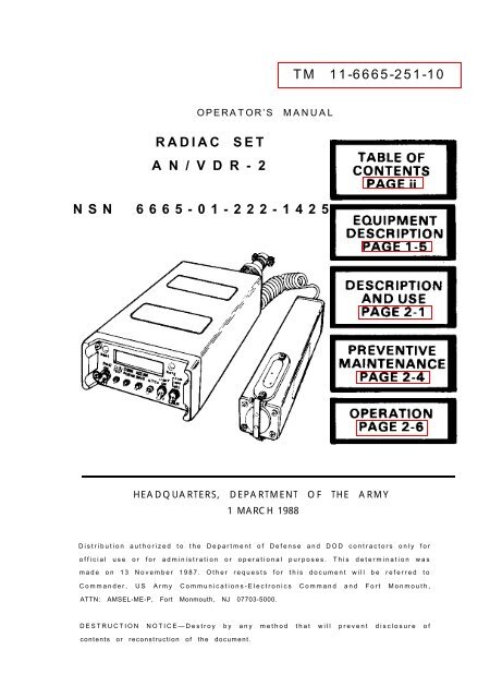
TM 11-<strong>6665</strong>-251-10<br />
OPERATOR’S M<strong>AN</strong>UAL<br />
<strong>RADIAC</strong> <strong>SET</strong><br />
A N / V D R - 2<br />
<strong>NSN</strong> <strong>6665</strong>-<strong>01</strong>-<strong>222</strong>-<strong>1425</strong><br />
HEADQUARTERS, DEPARTMENT OF THE ARMY<br />
1 MARCH 1988<br />
Distribution authorized to the Department of Defense and DOD contractors only for<br />
official use or for administration or operational purposes. This determination was<br />
made on 13 November 1987. Other requests for this document will be referred to<br />
Commander, US Army Communications-Electronics Command and Fort Monmouth,<br />
ATTN: AMSEL-ME-P, Fort Monmouth, NJ 07703-5000.<br />
DESTRUCTION NOTICE—Destroy by any method that will prevent disclosure of<br />
contents or reconstruction of the document.
TM 11-<strong>6665</strong>-251-10<br />
Technical Manual<br />
HEADQUARTERS<br />
DEPARTMENT OF THE ARMY<br />
No. 11-<strong>6665</strong>-251-10 Washington, DC, 1 March 1988<br />
Operator’s Manual<br />
Radiac Set<br />
<strong>AN</strong>/<strong>VDR</strong>-2<br />
(<strong>NSN</strong> <strong>6665</strong>-<strong>01</strong>-<strong>222</strong>-<strong>1425</strong>)<br />
REPORTING ERRORS <strong>AN</strong>D<br />
RECOMMENDING IMPROVEMENTS<br />
You can help improve this manual. If you find any<br />
mistake or if you know of a way to improve the<br />
procedures, please let us know. Mail your letter or<br />
DA Form 2028 (Recommended Changes to Publications<br />
and Blank Farms) direct to: Commander, US Army<br />
Communications-Electronics Command and Fort<br />
Monmouth, ATTN: AMSEL-ME-MP, Fort Monmouth, New<br />
Jersey 07703-5000. In either case, a reply will be sent<br />
to you.<br />
i
TABLE OF CONTENTS<br />
CHAPTER 1. INTRODUCTION<br />
Para- Page<br />
graph<br />
Section I.<br />
General<br />
Scope . . . . . . . . . . . . . . . . . . . . . 1-1<br />
Maintenance Forms,<br />
Records, and Reports . . . . 1-2<br />
Reporting Equipment<br />
Improvement<br />
Recommendations (EIR) . 1-3<br />
Administrative Storage . . . . 1-4<br />
Destruction of Army<br />
Electronics Materiel. . . . . 1-5<br />
Nomenclature<br />
Cross-Reference List . . . 1-6<br />
List of Abbreviations and<br />
Acronyms . . . . . . . . . . . . . . . 1-7<br />
Glossary . . . . . . . . . . . . . . . . . . . 1-8<br />
1-1<br />
1-2<br />
1-2<br />
1-2<br />
1-3<br />
1-3<br />
1-3<br />
1-4<br />
Section Il. EQUIPMENT DESCRIPTION<br />
<strong>AN</strong>D DATA<br />
Equipment Characteristics,<br />
Capabilities,<br />
and Features . . . . . . . . . . . . 1-9 1-5<br />
Description of<br />
Components . . . . . . . . . . . . . 1-10 1-6<br />
Equipment Data . . . . . . . . . . . 1-11 1-10<br />
Section III. TECHNICAL PRINCIPLES OF<br />
OPERATION<br />
ii<br />
Equipment Function . . . . . . . 1-12 1-14
TABLE OF CONTENTS (CONTINUED)<br />
CHAPTER 2. OPERATING<br />
INSTRUCTIONS<br />
Section I. DESCRIPTION <strong>AN</strong>D<br />
USE OF CONTROLS<br />
<strong>AN</strong>D INDICATORS<br />
Para- Page<br />
graph<br />
Equipment Controls<br />
and Indicators . . . . . . . . . . . 2-1 2-1<br />
Section II. PREVENTIVE<br />
MAINTEN<strong>AN</strong>CE<br />
CHECKS <strong>AN</strong>D<br />
SERVICES (PMCS)<br />
Preventive Maintenance. . . 2-2 2-4<br />
Routine Checks . . . . . . . . . . . . 2-3 2-4<br />
Section III. OPERATION UNDER<br />
USUAL CONDITIONS<br />
Assembly and Preparation<br />
for Use . . . . . . . . . . . . . . . . . . 2-4 2-6<br />
Equipment Applications . . . 2-5 2-17<br />
Automatic Testing During<br />
Operation . . . . . . . . . . . . . . . 2-6 2-22<br />
Normal Operating<br />
Procedures . . . . . . . . . . . . . 2-7 2-25<br />
Operation in Unusual<br />
Weather . . . . . . . . . . . . . . . . 2-8 2-42<br />
Operation Inside Shelters . 2-9 2-43<br />
Emergency Procedures . . . . 2-10 2-43<br />
iii
TABLE OF CONTENTS (CONTINUED)<br />
Para- Page<br />
graph<br />
CHAPTER 3. OPERATOR<br />
MAINTEN<strong>AN</strong>CE<br />
INSTRUCTIONS<br />
Troubleshooting<br />
Procedures . . . . . . . . . . . 3-1 3-1<br />
Battery Replacement . . . . 3-2 3-2<br />
APPENDIX A. REFERENCES . . . . . . . . . . . . . . . . . . . A-1<br />
B. COMPONENTS OF<br />
END ITEM <strong>AN</strong>D<br />
BASIC ISSUE ITEMS<br />
LIST . . . . . . . . . . . . . . . . . . . . . . . . . . . B-1<br />
Section I. INTRODUCTION . . . . . . . . . . . . . . . . . . . . B-1<br />
II. COMPONENTS OF END<br />
ITEM . . . . . . . . . . . . . . . . . . . . . . . . . . . . . . B-3<br />
III. BASIC ISSUE ITEMS . . . . . . . . . . . . . . B-5<br />
APPENDIX C. EXPENDABLE<br />
SUPPLIES <strong>AN</strong>D<br />
MATERIALS LIST . . . . . . . . . . . . . . . C-1<br />
Section I. INTRODUCTION . . . . . . . . . . . . . . . . . . . . C-1<br />
iv<br />
II. EXPENDABLE<br />
SUPPLIES <strong>AN</strong>D<br />
MATERIALS LISTS . . . . . . . . . . . . . . . . C-2
CHAPTER 1<br />
INTRODUCTION<br />
Section I. GENERAL INFORMATION<br />
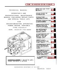
1-1. SCOPE<br />
Type of ManuaI: Operator’s Manual<br />
Model Number and Equipment Name:<br />
<strong>AN</strong>/<strong>VDR</strong>-2 Radiac Set, herein<br />
referred to as radiac set.<br />
Purpose of Equipment:<br />
Used to locate and<br />
measure radioactivity<br />
in the form of gamma<br />
rays and beta<br />
particles, Displays<br />
dose rates and total <strong>RADIAC</strong>METER<br />
accumulated dose<br />
resulting from a<br />
fallout field.<br />
PROBE<br />
1-1
1-2. MAINTEN<strong>AN</strong>CE FORMS, RECORDS<br />
<strong>AN</strong>D REPORTS<br />
a. Reports of Maintenance and Unsatisfactory<br />
Equipment. Department of the Army forms and<br />
procedures used for equipment maintenance<br />
will be those prescribed by DA Pam 738-750, as<br />
contained in Maintenance Management Update.<br />
b. Report of Packaging and Handling<br />
Deficiencies. Fill out and forward SF 364 (Report<br />
of Discrepancy (ROD)) As prescribed in AR 735-<br />
11-2/DLAR 4140.55/NAVMATlNST<br />
4355.73B/AFR 400-54/MCO 4430.3H.<br />
c. Discrepancv in Shipment Report (DISREP)<br />
(SF 361). Fill out and forward Discrepancy in<br />
Shipment Report (DISREP) (SF 361) as prescribed<br />
in AR 55-38/NAVSUPINST 4610.33C/AFR 75-<br />
18/MCO P4610.19D/DLAR 4500.15.<br />
1-3. REPORTING EQUIPMENT IMPROVEMENT<br />
RECOMMENDATIONS (EIR)<br />
If your equipment needs improvement, let us<br />
know. Send us on EIR. You, the user, are the<br />
only one who can tell us what you don’t like<br />
about the design. Put it on an SF 368 (Quality<br />
Deficiency Report). Mail it to Commander, US<br />
Army Communications-Electronics Command<br />
and Fort Monmouth, ATTN: AMSEL-ME-MP, Fort<br />
Monmouth, New Jersey 07703-5000. We’ll send<br />
you a reply.<br />
1-4. ADMINISTRATIVE STORAGE<br />
Administrative storage of equipment issued to<br />
1-2
and used by Army activities will have preventive<br />
maintenance performed in accordance with the<br />
PMCS charts before storing. When removing the<br />
equipment from administrative storage the PMCS<br />
should be performed to assure operational<br />
readiness.<br />
1-5. DESTRUCTION OF ARMY<br />
ELECTRONICS MATERIEL<br />
Destruction of Army electronics materiel to<br />
prevent enemy use shall be in accordance with<br />
TM 750-244-2.<br />
1-6. NOMENCLATURE CROSS-REFERENCE LIST<br />
Common names are used when the major components<br />
of the radiac set are mentioned in this<br />
manual.<br />
Common Name<br />
Radiac Set<br />
Official Nomenclature<br />
Radiac Set<br />
<strong>AN</strong>/<strong>VDR</strong>-2<br />
Radiacmeter Radiacmeter lM-243/<strong>VDR</strong>-2<br />
Probe<br />
Pouch<br />
Probe, Radiac DT-616/<br />
<strong>VDR</strong>-2<br />
Pouch, Radiac Set<br />
Strap<br />
Strap, Radiac Set<br />
1-7. LIST OF ABBREVIATIONS <strong>AN</strong>D<br />
ACRONYMS<br />
Acronyms are spelled out the first time they appear<br />
in this manual. A list of abbreviations and acronyms<br />
follows:<br />
1-3
Gy<br />
µGy<br />
cGy<br />
Gy/hr<br />
µGy/hr<br />
cGy/hr<br />
NBC<br />
radiation absorbed dose<br />
(gray)<br />
microgray<br />
centigray<br />
grays per hour<br />
micrograys per hour<br />
centigrays per hour<br />
nuclear/biological/chemical<br />
1-8. GLOSSARY<br />
Dose<br />
Rate<br />
Dose<br />
Gamma<br />
Ray<br />
An amount of radiation given off or<br />
absorbed within a given period of time.<br />
(µGy/hr, cGy/hr, Gy/hr).<br />
An accumulative amount of radiation<br />
given off or absorbed. (µGy, cGY, GY).<br />
Electromagnetic radiation of high energy<br />
(high penetration).<br />
Beta<br />
Particles<br />
Negatively charged particles moving at high<br />
speed (low penetration).<br />
X-rays<br />
Auto<br />
ranging<br />
Electromagnetic radiation of high energy<br />
having wavelength shorter than those in<br />
the ultraviolet region (low penetration).<br />
The <strong>AN</strong>/<strong>VDR</strong>-2 display will automatically<br />
provide the proper readings and units over<br />
its entire operating range without the<br />
need for mechanical switching or other<br />
operator actions.<br />
1-4
Attenuation<br />
Factor<br />
A multiplying number assigned to<br />
vehicles or shielded enclosures to<br />
account for the attenuation of<br />
gamma radiation by the vehicle<br />
or the enclosure.<br />
Section II EQUIPMENT DESCRIPTION <strong>AN</strong>D<br />
DATA<br />
1-9. EQUIPMENT CHARACTERISTICS,<br />
CAPABILITIES, <strong>AN</strong>D FEATURES.<br />
CHARACTERISTICS<br />
● Lightweight<br />
● Easy to use<br />
Battery operated<br />
Self-testing during operation or on demand<br />
by operator<br />
● Autoranging<br />
CAPABILITIES<br />
● Detects, measures, and displays level of<br />
gamma radiation dose rate from 0.<strong>01</strong> µGy/hr.<br />
to 100 Gy/hr.<br />
● Detects and displays level of beta particle<br />
dose rate from 0.<strong>01</strong> µGy/hr. to 5 cGy/hr.<br />
● Measures, stores, and displays accumulated<br />
dose from 0.<strong>01</strong> µGy to 9.99 Gy.<br />
1-5
● Flashes display to indicate reduced-accuracy<br />
condition when measuring dose rates from<br />
10 Gy/hr. and above.<br />
FEATURES<br />
● Liquid crystal display (LCD) shows three digits,<br />
decimal point, and unit of measure for dose<br />
rate or accumulated dose; also indicates<br />
low batteries and faults<br />
● Can be vehicle mounted with vehicle power<br />
actuating alarms and intercoms; computes<br />
and displays dose rates external to vehicle<br />
● Audible or visual alarm independently preset<br />
for dose rate and accumulated dose<br />
1-10. DESCRIPTION OF COMPONENTS<br />
The radiac set is made up of four separate pieces<br />
of equipment:<br />
● Radiacmeter<br />
● Probe<br />
● Pouch<br />
● Strap<br />
1-6<br />
NOTE<br />
Radiacmeter and probe are serialized and<br />
must be kept together as a set.
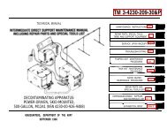
The functions of the major components of this<br />
equipment are:<br />
<strong>RADIAC</strong>METER - Contains<br />
batteries, controls,<br />
indicators, and<br />
electronics needed to<br />
measure and display<br />
dose rate, dose, and<br />
other indications.<br />
LOUDSPEAKER - Provides<br />
audible alarm<br />
DISPLAY - Shows<br />
dose/hr or accumulated<br />
dose, low batteries,<br />
alarm set points, and<br />
test and fault indicators.<br />
1-7
BATTERY WELL COVER<br />
Encloses battery well<br />
containing three dry cell<br />
batteries providing power<br />
to the radiac set.<br />
CONVERTER CABLE<br />
RECEPTACLE (SHOWN<br />
WITH CAP IN PLACE)<br />
Connects radiacmeter to<br />
vehicle power converter<br />
cable.<br />
1-8<br />
CAUTION<br />
The radiac set will not operate with probe<br />
detached and can be damaged if probe is<br />
attached or detached with PWR switch in<br />
ON position.
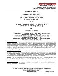
PROBE - Attaches to<br />
radiacmeter with coil cord and<br />
connector; contains two<br />
detectors, high-voltage power<br />
supply, and other circuits.<br />
PROBE RECEPTACLE<br />
- Accepts plug from<br />
radiacmeter cable.<br />
WARNING<br />
The high range<br />
detector contains 1<br />
nanocurie of Thorium<br />
232, controlled disposal<br />
required in accordance<br />
with AR 385-11.<br />
HOUSING - Contains<br />
low-range detector and<br />
electronic circuitry.<br />
DETECTOR GUARD -<br />
Protects low-range detector,<br />
keeps moisture out of probe.<br />
COVER - Protects detector<br />
against damage; can be used<br />
closed to detect gamma<br />
radiation, must be opened to<br />
detect beta particles.<br />
1-9
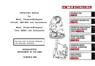
POUCH - Holds radiacmeter<br />
and probe during operation or<br />
transport and stores spare set<br />
of batteries. May be attached<br />
to web belt with belt loops.<br />
1-11. EQUIPMENT DATA<br />
ENVIRONMENTAL<br />
Altitude operating To 15,000 feet<br />
range:<br />
(4,572 m) above<br />
sea level<br />
Humidity:<br />
95 percent<br />
Temperature operating<br />
range: -51 to 120°F<br />
(-46 to +49°C)<br />
1-10
Storage temperature<br />
range: -60 to 160°F<br />
(-51 to + 71°C)<br />
Water resistance:<br />
Immersion proof to a<br />
depth of 3 feet<br />
(914.4 mm) of<br />
water for 2 hours<br />
WEIGHTS <strong>AN</strong>D DIMENSIONS<br />
Radiac set in pouch:<br />
Weight:<br />
Length:<br />
Width:<br />
Depth:<br />
4.6 pounds (2.08 kg)<br />
9.125 inches (232 mm)<br />
6.875 inches (175 mm)<br />
3.125 inches (79 mm)<br />
POWER<br />
Main power,<br />
all weather<br />
Three BA-3090 dry<br />
batteries in parallel<br />
(9 V dc) (Item 1, Appx C)<br />
Vehicle power<br />
(when vehicle<br />
mounted):<br />
Main Power<br />
battery life:<br />
24 V dc<br />
100 hours (minimum)<br />
1-11
OPERATIONAL<br />
Detectors:<br />
Range:<br />
a) Low-range detector<br />
(dose rate):<br />
b) Low-range detector<br />
(accumulated<br />
dose):<br />
c) High-range detector<br />
(dose rate):<br />
d) High-range detector<br />
(accumulated<br />
dose):<br />
Two detectors (lowrange<br />
for gamma and<br />
beta radiation, highrange<br />
for gamma radiation),<br />
both located in<br />
probe at approximately<br />
the same location.<br />
0.<strong>01</strong> µGy/hr<br />
to 5C Gy/hr.<br />
0.<strong>01</strong> µGy to<br />
9.99 Gy.<br />
3 cGy/h to<br />
100 Gy/Hr.<br />
0.<strong>01</strong> µGy to<br />
9.99 Gy.<br />
1-12
Overall detecting range:<br />
Dose rate:<br />
Accumulated<br />
dose:<br />
Accuracy:<br />
Dose:<br />
Alarms:<br />
0.<strong>01</strong> µGy/hr. to<br />
100. Gy/hr for<br />
gamma rays and<br />
0.<strong>01</strong> µGy/hr. to<br />
5 C Gy/hr for beta<br />
radiation<br />
0.<strong>01</strong> µGy to<br />
9.99 Gy.<br />
Dose rate: ±20 percent (overall<br />
system error) up to<br />
10.0 Gy/hr.<br />
±25 percent (overall<br />
system error) up to<br />
100 Gy/hr.<br />
±20 percent (overall<br />
system error) up to<br />
9.99 Gy.<br />
Audio and visual independently<br />
adjustable<br />
to any level from<br />
0.0 µGy/hr. to 100<br />
Gy/hr. for dose rate<br />
and 0.<strong>01</strong> µGy to<br />
9.99 Gy for<br />
accumulated dose.<br />
1-13
Section III. TECHNICAL PRINCIPLES<br />
OF OPERATION<br />
1-12. EQUIPMENT FUNCTION<br />
1 Gamma rays and beta particles<br />
from radioactive source travel in<br />
all directions.<br />
1-14<br />
2 Two detectors in probe produce<br />
electrical signals on contact with<br />
gamma rays and beta particles.
3 Radiacmeter converts signals<br />
from probe into dose rates and<br />
accumulated dose; activates<br />
alarm when preset alarm levels<br />
ae exceeded.<br />
4 Display shows dose rate and<br />
accumulated dose values, alarm<br />
set levels, battery conditions,<br />
and test and fault indicators.<br />
5 Control panel switches and<br />
indicators permit operator to set<br />
alarm levels for audible or visual<br />
display, select display readings,<br />
and perform equipment tests.<br />
1-15/(1-16 Blank)
CHAPTER 2<br />
OPERATING INSTRUCTIONS<br />
Section I. DESCRIPTION <strong>AN</strong>D USE OF<br />
CONTROLS <strong>AN</strong>D INDICATORS<br />
2-1. EQUIPMENT CONTROLS <strong>AN</strong>D<br />
INDICATORS<br />
a. TOGGLE SWITCHES <strong>AN</strong>D ALARM LIGHTS<br />
RATE <strong>AN</strong>D DOSE LIGHTS - Illuminate<br />
when dose rate or accumulated dose alarm<br />
set points are exceeded and alarm is set to<br />
VlS.<br />
POWER - Turns unit ON or OFF.<br />
THREE-POSITION ALARM<br />
● OFF (center) - NO alarm occurs.<br />
● AUD (top) - Alarm sounds when either<br />
alarm set point is exceeded.<br />
● VIS (bottom) - RATE or DOSE light<br />
illuminates when either alarm set point is<br />
exceeded.<br />
2-1
. PUSHBUTTONS<br />
CLEAR/TEST - Pressed to start operating<br />
test; used with other buttons to perform<br />
various test functions.<br />
DOSE PER HOUR - Used with other<br />
buttons to:<br />
Set dose rate alarm.<br />
Display dose rate alarm set point<br />
Clear accumulated dose.<br />
ACCUMULATED DOSE - Pressed to<br />
display accumulated dose; used with other<br />
buttons to perform various functions.<br />
ATTENUATION - Press to display dose<br />
external to vehicle when vehicle mounted;<br />
used with CLR/TEST button to read<br />
attenuation factor.<br />
2-2
DOSE UNITS - Proper symbol (µGy, cGY, Gy)<br />
activated automatically according to<br />
radiation reading.<br />
2-3
Section II. PREVENTIVE MAINTEN<strong>AN</strong>CE<br />
CHECKS <strong>AN</strong>D SERVICES (PMCS)<br />
2-2. PREVENTIVE MAINTEN<strong>AN</strong>CE<br />
Preventive maintenance consists of routine checks<br />
of the equipment before and after each mission, or<br />
at any time they are necessary. Routine checks<br />
include cleaning, dusting, and washing the set;<br />
checking for worn cables; replacing receptacle<br />
covers; and putting away items that are not used.<br />
Problems discovered during routine maintenance<br />
should be referred to organizational maintenance.<br />
2-3. ROUTINE CHECKS<br />
Routine checks to be made of the radiac set are:<br />
● Check all connecting cables, receptacles, and<br />
plugs for cracks and breaks.<br />
CAUTION<br />
Turn unit off before disconnecting<br />
or reconnecting probe.<br />
● Check that cable receptacle pins are unbroken<br />
and straight. There should be three pins in the<br />
vehicle mount receptacle on the back of the<br />
radiacmeter and six in the receptacle located<br />
on the probe.<br />
2-4
CONTROL <strong>AN</strong>D DISPLAY P<strong>AN</strong>EL<br />
●<br />
●<br />
Check for loose or broken display lights or<br />
light covers.<br />
Inspect panel toggle switches and<br />
pushbuttons for ease of movement or<br />
evidence of mechanical damage.<br />
OUTSIDE SURFACES <strong>AN</strong>D POUCH<br />
Remove dust, moisture, and loose dirt<br />
from outside surfaces of radiacmeter and<br />
probe with clean soft cloth.<br />
Remove grease, fungus, and ground-in<br />
dirt from equipment pouch.<br />
BATTERIES<br />
●<br />
●<br />
Inspect battery well gasket (see para<br />
2-4a). Refer radiac set to higher level of<br />
maintenance only if gasket will no longer<br />
seal.<br />
Inspect battery contacts; remove any<br />
corrosion using pencil eraser.<br />
2-5
Section III. OPERATION UNDER<br />
USUAL CONDITIONS<br />
2-4. ASSEMBLY <strong>AN</strong>D PREPARATION FOR USE<br />
a. BATTERY INSTALLATION/REPLACEMENT<br />
(1) Make sure PWR switch is OFF (down).<br />
(2) Loosen, but do not remove,<br />
captive screws.<br />
2-6
CAUTION<br />
When batteries are removed<br />
from the radiac set memory<br />
is retained for only 5<br />
minutes.<br />
(3) Remove battery well cover<br />
and three batteries.<br />
2-7
. INSTALLING <strong>RADIAC</strong> <strong>SET</strong> IN POUCH<br />
(1) Orient pouch so that tap cover is open<br />
and away from you. Install probe in the left<br />
compartment by passing the straight<br />
section of the tail card nearest the probe<br />
connector through the opening in the<br />
compartment flaps. (Note the orientation of<br />
the high range assembly.) Push probe to the<br />
bottom of pouch.<br />
2-8
(2) Store coil cord at the bottom of the right<br />
hand compartment. Install radiacmeter<br />
directly above coil cord as shown.<br />
<strong>RADIAC</strong>METER<br />
COIL CORD<br />
2-9
c. PREOPERATIONAL TEST EXPL<strong>AN</strong>ATION<br />
Before each mission, a series of preoperational<br />
tests must be performed to<br />
make sure that the radiac set is operating.<br />
The radiac set is self-testing and the preoperational<br />
tests are performed automatically<br />
by the equipment. The operator<br />
is required to reposition the alarm switch<br />
and observe closely that the proper displays<br />
are shown for the test being conducted.<br />
NOTE<br />
A summary of these tests is listed in<br />
sequence below. Although these tests seem<br />
difficult at first, they are easy to perform<br />
after following the sequence a few times.<br />
(1) Segment Test - Segments of the digital<br />
display, decimal points and unit readout are<br />
displayed for about 10 seconds to<br />
determine that all display segments are<br />
working. The alarm test (step (2) below),<br />
must be performed during the 10<br />
seconds the segments are displayed.<br />
2-10
(2) Alarm Test - Operator switches ALM to all<br />
positions to check that the alarm sounds and<br />
shuts off and that the lights work at the proper<br />
times.<br />
(3) Digit/Unit Test - After the segment test, the unit<br />
automatically proceeds through the sequence of<br />
numbers, decimal places, and dose units to test<br />
that they are working in the proper order. This<br />
test and the following electrical tests take about<br />
60 seconds.<br />
(4) Electrical Tests - Immediately following the<br />
sequential displays, a series of eight internal<br />
electrical tests occurs. During these tests, onedigit<br />
numbers may appear on the display. These<br />
are the code numbers related to the test being<br />
made and you can ignore them.<br />
2-11
NOTE<br />
All of the following paragraphs must be<br />
read before starting test procedures.<br />
d.<br />
(1)<br />
(2)<br />
(3)<br />
PREOPERATIONAL TEST PROCEDURES<br />
Set PWR to ON (up).<br />
Set ALM switch to AUD (up).<br />
Press and hold CLR/TEST button until<br />
alarm sounds 2 seconds, then release.<br />
(4)<br />
When segment display appears, check that<br />
your display is exactly as shown here, and<br />
then perform all of step (5) within 10 seconds.<br />
2-12
(5) Set ALM switch to OFF (center). Alarm<br />
sound stops.<br />
Set ALM switch to VIS (down). RATE and<br />
DOSE lights come on.<br />
Set ALM switch back to AUD (up). Lights<br />
go out, alarm sounds.<br />
Set ALM switch to OFF (center).<br />
(6) At the end of the 10-second segment test,<br />
the digit/unit test begins with three zeros<br />
and the sequence shown. Check each<br />
display in the sequence for correctness of<br />
all characters, including decimals.<br />
2-13
(7)<br />
During the electrical tests that start<br />
immediately after the 999Gydisplay, you<br />
may see one-digit codes on the display. You<br />
can ignore these codes.<br />
(8)<br />
If all tests are OK, after 10 to 60 seconds, a<br />
flashing 9 appears with the pulsating alarm.<br />
When you see the flashing 9, proceed to<br />
step (10) below.<br />
FLASHING<br />
(9)<br />
If there is a fault discovered during this test,<br />
a flashing 0 appears and the alarm<br />
pulsates. Turn unit OFF.<br />
FLASHING<br />
2-14
(10) Press and release CLR/TEST button.<br />
Preoperational tests are complete. Display again<br />
shows the three zeros (a) and then indicates dose<br />
rate, which is variable (b). Radiac set is ready for<br />
normal operation.<br />
CLR/TEST<br />
BUTTON<br />
2-15
(11) If any of the following events occur during<br />
the preoperational tests, turn unit OFF and<br />
send to organizational maintenance for<br />
repair.<br />
Power does not come on (step 1).<br />
Alarm does not sound (step 3).<br />
Decimal points, dose units, or any segment<br />
of the display are not in position or<br />
otherwise not exactly as shown (step 4).<br />
● Alarm does not turn off (step 5).<br />
RATE and/or DOSE lights do not come on<br />
(step 5).<br />
● Alarm does not turn on again (step 5).<br />
● Digit/unit test are not displayed in entirety,<br />
in sequence exactly as shown (step 6).<br />
● The electrical tests end with the display<br />
showing a flashing 0 (step 9).<br />
NOTE<br />
When performing preoperational tests in<br />
an area where the background radiation is<br />
unusually low or when the probe is<br />
shielded, it is statistically possible for the<br />
high range tube not to produce a count in<br />
the time allowed in the test. This will cause<br />
a flashing zero to appear when in fact no<br />
fault exists. If the numeral 7 appears prior<br />
to a flashing zero, repeat the preoperational<br />
test. If a flashing 9 appears on<br />
the retest no fault exists. If the flashing zero<br />
repeats, refer the unit to maintenance.<br />
2-16
2-5. EQUIPMENT APPLICATIONS<br />
There are three methods used to locate radiological<br />
contamination - Surveying, Monitoring, and<br />
Ground Radiological Reconnaissance:<br />
● Surveying - Surveys are conducted to find<br />
the extent and intensity of contamination.<br />
There are two types, aerial and ground.<br />
NOTE<br />
To perform aerial surveys, auxiliary<br />
equipment is required which is not<br />
supplied with the <strong>AN</strong>/<strong>VDR</strong>-2.<br />
● Aerial surveys cover a large area faster<br />
than other methods. They are more flexible<br />
and require fewer personnel and less<br />
exposure of personnel.<br />
● Ground surveys use unit equipment and<br />
can be performed in any type of weather or<br />
at night. They are more accurate than aerial<br />
surveys.<br />
Monitoring - Monitoring is performed to<br />
determine the presence and intensity of<br />
residual radiation.<br />
Area monitoring is performed periodically or<br />
continuously to provide early warning and<br />
useful radiological data.<br />
● Personnel, food, and equipment monitoring<br />
is performed to detect beta and low levels of<br />
gamma radiation.<br />
2-17
●<br />
Ground Radiological Reconnaissance (GRR)<br />
- GRR is the process of detecting radiation<br />
and measuring it before a unit moves into<br />
or through an area. Normally, the <strong>AN</strong>/<strong>VDR</strong>-<br />
2 will be mounted and attached to vehicle<br />
power.<br />
NOTE<br />
When monitoring for beta radiation, the<br />
audible alarm set point should be used. This<br />
allows the operator to pay attention to<br />
positioning the probe rather than watching<br />
the visual display. Performance of all<br />
radiological measurements, regardless of<br />
mode of operation, shall be in accordance<br />
with FM 3-3 and FM 3-5.<br />
a. SURVEY <strong>AN</strong>D MONITORING MODES<br />
In the survey or monitoring modes,<br />
the operator wears the radiac set in<br />
the pouch with the PWR switch in the<br />
ON position. The probe can be carried<br />
either in the pouch or held in the<br />
hand, as desired.<br />
2-18
The probe cover, located at the end of<br />
the probe, is closed when measuring<br />
gamma radiation. Detection is<br />
provided by both low-range and highrange<br />
detectors located in the probe.<br />
The radiac set autoranges from low to<br />
high range (0.<strong>01</strong> µGy/-hr to 100<br />
Gy/hr.) smoothly and without<br />
interruption.<br />
CAUTION<br />
The window guard may be ruptured by<br />
sharp objects. Use extreme care to protect<br />
window guard when probe window is open<br />
(when monitoring for beta radiation).<br />
When monitoring for beta radiation,<br />
the probe must be hand held, and the<br />
probe window cover must be open to<br />
allow beta particles to enter the<br />
window of the low-range detector.<br />
Only the low-range detector is capable<br />
of detecting beta particles. The range<br />
of beta radiation is 0.<strong>01</strong> µGy/hr to 5<br />
cGy/hr.<br />
2-19
. GROUND RADIOLOGICAL<br />
RECONNAISS<strong>AN</strong>CE (VEHICULAR<br />
OPERATION)<br />
CAUTION<br />
The radiacmeter batteries must be removed<br />
when using vehicular power.<br />
When used in a vehicle, the radiac set is placed<br />
in a mount and installed using an installation kit.<br />
The mount(MT-6123/<strong>VDR</strong>-2) is not supplied with<br />
the <strong>AN</strong>/<strong>VDR</strong>-2 or the installation kit. Vehicular<br />
power is used to operate the set through a<br />
voltage converter (24V to 7.8V).<br />
2-20
NOTE<br />
When the unit is mounted in a vehicle and<br />
the vehicle is turned off, the power to the<br />
unit is lost. If this condition lasts for more<br />
than 5 minutes, the unit memory is lost.<br />
When memory is lost, the prior<br />
accumulated dose cannot be recalled, and<br />
the alarm set points set previously by the<br />
operator are also lost. Alarm set points will<br />
revert to the points set internally in the<br />
radiacmeter, until the operator sets new<br />
alarm points from the front panel.<br />
If the commander requires that prior<br />
accumulated dose be maintained and the<br />
vehicle is turned off, batteries must be<br />
installed in the radiac set within 5 minutes<br />
from the time the vehicle is turned off. See<br />
paragraph 2-10c(1)for battery replacement<br />
procedure.<br />
2-21
2-6. AUTOMATIC TESTING<br />
DURING OPERATION<br />
In addition to the pre-operational tests described<br />
in paragraph 2-4c, the radiac set tests itself<br />
continuously during operation. These tests check<br />
the main battery condition, counting and timing<br />
sequences, internal circuitry, voltage, and<br />
detectors.<br />
a. LOW-BATTERY INDICATOR<br />
If a low battery condition is detected during these<br />
tests, the /hr sign will be shown flashing on the<br />
display. Approximately 10 hours of useful battery<br />
life remain from the moment the low-battery<br />
indicator is first displayed.<br />
2-22<br />
NOTE<br />
When you see this low-battery display, use<br />
the LIGHT as little as possible and replace<br />
the batteries at the first opportunity (see<br />
para 2-4a).
. GENERAL FAULT INDICATOR<br />
To indicate problems other than low<br />
batteries discovered during automatic<br />
testing, the general fault indicator (flashing<br />
0) is displayed.<br />
If your radiac set displays the general fault<br />
indicator during operation or testing,<br />
immediately turn the unit OFF and send to<br />
organizational maintenance for repair.<br />
2-23
c. DELAYED GENERAL FAULT INDICATOR<br />
If the high-range detector becomes defective, the<br />
general fault indicator (flashing 0) is not<br />
displayed immediately, as in the case of all other<br />
electrical faults. The fault indicator has been<br />
delayed 3 minutes so that the operator has time<br />
to observe the display and perform additional<br />
tests.<br />
If the display alternates between a high and low<br />
reading, as shown below, this can be due to a<br />
defect in the high-range tube, or because the<br />
low-range tube (provided the probe cover is open)<br />
is responding to beta radiation in excess of<br />
5cGy/hr. Because the high-range tube is<br />
insensitive to beta radiation, the alternating highand<br />
low-range readings will be normal in this<br />
case.<br />
While the alternating indication is displayed, the<br />
operator should close the probe cover to shield<br />
the low-range tube from beta radiation. If the<br />
alternating indication no longer occurs, no fault<br />
exists. If it continues, the high-range tube is<br />
defective and the radiac set should be referred to<br />
organizational maintenance.<br />
2-24
2-7. NORMAL OPERATING PROCEDURES<br />
a. READ DOSE RATE<br />
NOTE<br />
All you have to do to read dose rate is turn<br />
the unit ON. After any operation, the<br />
display always returns to dose rate.<br />
Set PWR switch to ON.<br />
NOTE<br />
Emission from radioactive materials is<br />
random; it does not occur at a uniform rate.<br />
This causes fluctuations in the readings<br />
displayed by the radiac set.<br />
2-25
. ILLUMINATE OR DARKEN DISPLAY<br />
CAUTION<br />
Over-use of the display light will drain the<br />
batteries.<br />
With PWR switch ON, turn light ON (up) or<br />
OFF (down).<br />
c. READ ACCUMULATED DOSE<br />
With PWR switch ON, press and hold ACCUM<br />
DOSE button to read accumulated dose, then<br />
release button.<br />
2-26
d. CLEAR ACCUMULATED DOSE<br />
(1) Press and hold ACCUM DOSE and DOSE<br />
PER HR buttons<br />
(2)<br />
With both these buttons down, press and<br />
hold CLR/TEST button<br />
2-27
While all three buttons are down, the<br />
previous accumulated dose clears. All three<br />
buttons must be held until display reads:<br />
When the three buttons are released the<br />
display will show dose rate.<br />
e. DISPLAY DOSE RATE ALARM <strong>SET</strong> POINT<br />
(1)<br />
(2)<br />
(3)<br />
Press and hold DOSE PER HR button<br />
With button pressed, press and hold<br />
CLR/TEST button until alarm set point<br />
for dose rate is displayed in a flashing<br />
mode.<br />
Release both buttons.<br />
2-28
While both buttons are released, display<br />
flashes the dose rate alarm set point shown<br />
above for 10 seconds, then reverts to<br />
normal operation and displays dose rate.<br />
f. DISPLAY ACCUMULATED DOSE ALARM<br />
<strong>SET</strong> POINT<br />
(1)<br />
(2)<br />
(3)<br />
Press and hold ACCUM DOSE button.<br />
While holding button down, press and hold<br />
CLR/TEST button until the accumulated<br />
dose set point is displayed in a flashing<br />
mode.<br />
Release both buttons.<br />
2-29
The display flashes the accumulated dose<br />
alarm set point shown above for 10<br />
seconds, then reverts to dose rate.<br />
g. TO <strong>SET</strong> ALARM MODE<br />
(1) Set ALM switch to AUD (up) for audio<br />
alarm.<br />
Alarm sounds when the dose rate or<br />
accumulated dose points are exceeded, or<br />
when a fault occurs.<br />
(2) Set ALM switch to VIS (down) for visual<br />
alarm.<br />
2-30
Appropriate RATE or DOSE light flashes<br />
when the alarm set point is exceeded or<br />
when a fault occurs.<br />
(3)<br />
Set ALM switch to OFF (center) for no<br />
alarm.<br />
h. <strong>SET</strong> DOSE RATE ALARM<br />
Setting the dose rate alarm set point involves<br />
entering the proper decimal point, range unit,<br />
(µGy/hr, cGy/hr, or Gy/hr), and first, second,<br />
and third digits into the radiacmeter memory.<br />
NOTE<br />
Read each of the steps in this procedure<br />
before trying to set the dose rate alarm. For<br />
the example below, a previous setting of<br />
1.00 cGy/hr is changed to 12.5 cGy/hr.<br />
(1) <strong>SET</strong>TING DECIMAL POINTS <strong>AN</strong>D UNITS<br />
2-31
(a)<br />
(b)<br />
Press and hold DOSE PER HR button<br />
While still holding the DOSE PER HR<br />
button, press and hold CLR/TEST until<br />
previous dose rate alarm set point is<br />
displayed in a flashing mode, then release<br />
both buttons.<br />
(c)<br />
Within 10 seconds, press and hold<br />
CLR/TEST button again until only<br />
decimal point and unit indicator are<br />
flashing. Release CLR/TEST button.<br />
Display remains the same as in step 2, but<br />
only decimal point and unit indicator flash:<br />
2-32
(d) While decimal point and unit indicator are<br />
flashing, press and release the DOSE PER<br />
HR button .Repeat this until the desired<br />
decimal point setting and units appear.<br />
(e) When certain that the desired combination<br />
of decimal point location and unit<br />
(µG/hr, cGy/hr, or G/hr) are shown,<br />
press and release CLR/TEST<br />
button.<br />
Decimal point and units are now locked into<br />
set. The display will flash the first digit:<br />
2-33
(2) <strong>SET</strong>TING FIRST DIGIT<br />
(a)<br />
(b)<br />
Press and release DOSE PER HR button<br />
until desired first digit appears. (The first<br />
digit in the example is the same as the<br />
previous setting, so go to step b.)<br />
When desired first digit appears, press and<br />
release CLR/TEST button .The first digit<br />
is locked into set.<br />
When the first digit has been locked into<br />
the set, the display will flash the second<br />
digit:<br />
2-34
(3) <strong>SET</strong>TING SECOND DIGIT<br />
(a) Press and release the DOSE PER HR<br />
button Continue pressing and releasing<br />
until the desired second digit appears (2 in<br />
the example).<br />
(b) When the desired digit appears, press and<br />
release CLR/TEST button<br />
The second digit is set and the display<br />
flashes the third digit.<br />
2-35
(4) <strong>SET</strong>TING THIRD DIGIT<br />
(a)<br />
Press and release DOSE PER HR button<br />
Repeat until desired third digit appears<br />
(5 in the example).<br />
(b) Press and hold CLR/TEST button .The<br />
third digit has been set and the new dose<br />
rate alarm set point is displayed.<br />
When CLR/TEST button is<br />
released, the unit then returns to dose rate.<br />
2-36
i. <strong>SET</strong> ACCUMULATED DOSE ALARM<br />
<strong>SET</strong> POINT<br />
To enter the accumulated dose alarm set<br />
point, refer to step h, above, for setting<br />
the dose rate alarm set point, except<br />
substitute the ACCUM DOSE button for<br />
the DOSE PER HR button in each step.<br />
If the ALM switch is on VIS the DOSE<br />
light will flash instead of the RATE light.<br />
NOTE<br />
If the unit is installed in a vehicle and it<br />
is required to set the dose rate and/or dose<br />
alarms for radiation outside the vehicle,<br />
follow the procedures given in paragraphs<br />
2-7h and 2-7i except that the alarm set<br />
point values you set to must be divided by<br />
the attenuation factor assigned to the<br />
vehicle in which the radiac set is installed.<br />
For example, if the radiac set is installed in<br />
an M-1 tank which has an attenuation<br />
factor of 20.0 and you wish to set the dose<br />
rate alarm so that it alarms at an external<br />
2-37
j. READ ATTENUATION FACTOR<br />
NOTE<br />
The attenuation factor is different for<br />
different vehicles.<br />
M-1<br />
M2/M3<br />
M-60<br />
M-113<br />
M-151<br />
M-577<br />
M-880<br />
M-1008<br />
M-998<br />
20.0<br />
9.10<br />
23.0<br />
3.60<br />
1.30<br />
4.02<br />
2.00<br />
2.00<br />
1.70<br />
These factors are set by organizational<br />
maintenance. If the factor displayed on<br />
the set in your vehicle in the following<br />
operation does not agree with the factor<br />
listed for that type of vehicle, inform<br />
immediate supervisor.<br />
2-38
(1) Press and hold ATTEN button.<br />
(2) While holding ATTEN button, press<br />
CLR/TEST button.<br />
So long as both ATTEN and CLR/TEST<br />
buttons are pressed, the display indicates<br />
the attenuation factor that has been set by<br />
organizational maintenance.<br />
When button is released, unit returns to<br />
dose rate measured at the probe.<br />
2-39
k. READ DOSE RATE OUTSIDE VEHICLE<br />
NOTE<br />
Emission from radioactive materials is<br />
random; it does not occur at a uniform<br />
rate. This causes fluctuations in the<br />
readings displayed by the radiac set.<br />
(1) Press and hold ATTEN button.<br />
(2) Release ATTEN button.<br />
While button is pressed, display shows dose<br />
sensed at the probe mutiplied by the<br />
attenuation factor, as shown above.<br />
When the buttons are released, the display<br />
returns to dose rate at the probe.<br />
2-40
I. TURN UNIT OFF<br />
Set PWR switch to OFF.<br />
Power to the set is turned off, but stored<br />
information, such as accumulated dose and<br />
alarm set points, is retained.<br />
NOTE<br />
When batteries are removed from the<br />
radiac set memory is retained for only 5<br />
minutes.<br />
2-8. OPERATION IN UNUSUAL WEATHER<br />
At temperatures below -22°F (-30°C) it takes<br />
somewhat longer for characters to form on the<br />
display. The radiac set automatically corrects for<br />
this delay by sensing temperatures below -22°F (-<br />
30°C) and increasing the display time from every<br />
2 seconds to every 5 seconds. Operation of the<br />
set is normal otherwise.<br />
2-41
2-9. OPERATION INSIDE SHELTERS<br />
When monitoring inside shelters, fortifications,<br />
etc., (indirect technique) where radiation is<br />
attenuated when it reaches the probe, preoperational<br />
tests are performed in accordance<br />
with paragraph 2-4c, and normal operation is the<br />
same as if the set was vehicle mounted (see<br />
paragraph 2-7, procedures i and j).<br />
Your unit commander determines the attenuating<br />
factor for the type of shelter in accordance with<br />
FM 3-3 and organizational maintenance sets the<br />
factor.<br />
2-10. EMERGENCY PROCEDURES<br />
a. MISSING MAIN POWER BATTERIES<br />
If the low-battery indicator comes on and three<br />
fresh batteries are not available, the set will<br />
operate on two or a single battery, if necessary.<br />
However, operation with less than three batteries<br />
considerably shortens battery life. If operating on<br />
less than three batteries, use the LIGHT as little<br />
as possible and replace batteries at the first<br />
opportunity (see paragraph 2-4a).<br />
b. MEMORY LOSS<br />
Memory may be lost due to depleted batteries or<br />
when batteries are removed from the radiac set<br />
for more than 5 minutes. When this occurs and<br />
fresh batteries are installed, the number 8 will<br />
appear on the display during turn-on for about 2<br />
seconds and the alarm will sound if the ALM<br />
switch is set to AUD.<br />
2-42
When this condition occurs accumulated dose<br />
and alarm set points will be lost and cannot be<br />
recalled. The operator can, however, reset new<br />
alarm points (see 2-7h and 2-7i).<br />
If you do not reset the alarm points, the set<br />
responds with audible or visual alarm at 1.00<br />
cGy/hr. for dose rate and 1.20 cGy. for<br />
accumulated dose. (These points are set<br />
internally and cannot be changed by the<br />
operator.)<br />
c. LOSS OF VEHICLE POWER<br />
During vehicle-mounted operations, the batteries<br />
are removed from the set and power is derived<br />
from the vehicle-power supply (see paragraph 2-<br />
4a). If this supply does not operate or fails for any<br />
reason, the radiac set will not function.<br />
If you are certain that any apparent failure of the<br />
radiac set is caused by loss of vehicle power,<br />
operation can be partially restored to the set by<br />
disconnecting it from vehicle power and installing<br />
batteries. Under this condition the set works<br />
properly except for the intercom alarm and NBC<br />
(Nuclear/Biological/Chemical) system alarm,<br />
which do not function without vehicle power.<br />
Carefully follow the steps below to remove the set<br />
from the mount and install batteries.<br />
(1) EMERGENCY BATTERY INSTALLATION<br />
(a) Be sure PWR switch is set to OFF.<br />
2-43
(b)<br />
(c)<br />
Disconnect VEHICLE POWER PLUG from<br />
VEHICLE POWER CONVERTER<br />
RECEPTACLE.<br />
Loosen (do not remove) RETAINING SCREWS<br />
and raise TOP COVER.<br />
2-44
(d) Disconnect CONVERTER CABLE PLUG<br />
from receptacle.<br />
(e) Install batteries (see paragraph 2-4a,<br />
and connect receptacle cap.<br />
2-45
(f)<br />
Position coil cord connecting the probe<br />
to the radiacmeter to the back of the unit<br />
through the opening between the top<br />
cover and shelf.<br />
(g)<br />
Position radiacmeter squarely on shelf<br />
above probe and center between LOCKING<br />
LUGS.<br />
2-46
(h) Close TOP COVER to position radiacmeter<br />
against POSITIONING TAB.<br />
(i) Tighten the two RETAINING SCREWS.<br />
(j) Perform operating tests (para 2-4d).<br />
(k) At completion of mission, notify organizational<br />
maintenance of the loss of<br />
vehicle power to radiacmeter.<br />
2-47 /(2-48 Blank)
CHAPTER 3<br />
OPERATOR MAINTEN<strong>AN</strong>CE<br />
INSTRUCTIONS<br />
3-1. TROUBLESHOOTING PROCEDURES<br />
This manual cannot cover all the problems that<br />
could happen when using the radiac set. The<br />
troubleshooting chart lists those problems that<br />
are most likely to occur during the operation or<br />
maintenance of the set. If one of these<br />
malfunctions occurs, perform the test or<br />
inspection and corrective action in the order<br />
listed. If a trouble is not listed or it is not<br />
corrected after performing the recommended<br />
corrective action, notify you supervisor. See<br />
Table 3-1.<br />
Table 3-1. TROUBLESHOOTING<br />
MALFUNCTION<br />
TEST OR INSPECTION<br />
CORRECTIVE ACTION<br />
1. DISPLAY IS BL<strong>AN</strong>K WHEN UNIT IS<br />
TURNED ON (NOT VEHICLE<br />
MOUNTED).<br />
Install new batteries (para 24-a).<br />
3-1
Table 3-1. TROUBLESHOOTING<br />
(CONTINUED)<br />
MALFUNCTION<br />
TEST OR INSPECTION<br />
CORRECTIVE ACTION<br />
2. DISPLAY IS BL<strong>AN</strong>K WHEN UNIT IS<br />
TURNED ON (VEHICLE MOUNTED).<br />
Check that all connectors are securely<br />
connected.<br />
Tighten any loose connectors.<br />
3. DISPLAY INDICATES NUMERAL 0<br />
WHEN UNIT IS TURNED ON.<br />
Check that probe is securely connected to<br />
radiacmeter cable.<br />
Connect probe to radiacmeter cable.<br />
4. IMPROPER OR NO ALARM<br />
INDICATIONS DURING NORMAL<br />
OPERATION.<br />
Check alarm set points,<br />
3-2. BATTERY REPLACEMENT.<br />
See paragraph 2-4a.<br />
Reset alarm set points.<br />
3-2
APPENDIX A<br />
REFERENCES<br />
A-1. SCOPE<br />
This appendix lists forms and publications that<br />
are referenced in this manual or that contain<br />
information applicable to the operation and<br />
maintenance of the <strong>AN</strong>/<strong>VDR</strong>-2 Radiac Set.<br />
A-2. FORMS<br />
Equipment Inspection and<br />
Maintenance Worksheet . . . . . . . . DA Form 2404<br />
Quality Deficiency<br />
Report . . . . . . . . . . . . . . . . . . . . . . . . Standard Form<br />
368<br />
Recommended Changes to<br />
Equipment Technical<br />
Manuals . . . . . . . . . . . . . . . . . . . . DA Form 2028<br />
A-3. PUBLICATIONS<br />
Consolidated Index of<br />
Army Publications and<br />
Blank Forms . . . . . . . . . . . . . . . . . .DA Pam25-30<br />
Dry Battery Supply Data . . . . . . . . . . . . . . . SB-116<br />
FSC Class 6135; Dry<br />
Battery Management Data . . . . . . . . . . . SB 11-30<br />
A-1
Procedures for Destruction of<br />
Electronic Materiel to<br />
Prevent Enemy Use<br />
(Electronics Command) . . . . . TM 750-244-2<br />
The Army Maintenance<br />
Management System<br />
(TAMMS)<br />
. . . DA PAM 738-750<br />
A-2
APPENDIX B<br />
COMPONENTS OF END ITEM <strong>AN</strong>D<br />
BASIC ISSUE ITEMS LISTS<br />
Section I. INTRODUCTION<br />
B-1. SCOPE.<br />
This appendix lists components of end item and<br />
basic issue items for the <strong>AN</strong>/<strong>VDR</strong>-2. This list will<br />
help you keep track of items required for safe and<br />
efficient operation.<br />
B-2. GENERAL<br />
The Compoents of End Item and Basic Issue<br />
Items Lists are divided into the following<br />
sections:<br />
a. Section II. COMPONENTS <strong>AN</strong>D END ITEM.<br />
This listing is for informational purposes only and<br />
is not authority to requisition replacements.<br />
These items are part of the end item, but are<br />
removed and separately packaged for<br />
transportation or shipment. As part of the end<br />
item, these items must be with the end item<br />
whenever it is issued or transferred between<br />
property accounts. Illustrations are furnished to<br />
assist you in identifying the items.<br />
b. Section III. BASIC ISSUE ITEMS (BII).<br />
These are the minimum essential items required<br />
to place the <strong>AN</strong>/<strong>VDR</strong>-2 in operation, to operate it,<br />
and to perform emergency repairs. Although<br />
B-1
shipped separately, packaged BII must be with<br />
the <strong>AN</strong>/<strong>VDR</strong>-2 during operation and whenever it<br />
is transferred between property accounts. The<br />
illustrations will assist you with hard to identify<br />
items. This manual is your authority to<br />
request/requisition replacement VII, based on<br />
TOE/MTOE authorization of the end item.<br />
B-3. EXPL<strong>AN</strong>ATION OF COLUMNS<br />
The following provides explanation of<br />
columns found in 10 tabular listings:<br />
a. Column (1). ILLUSTRATION NUMBER<br />
(ILLUS. NO.). Indicates the number of the<br />
illustration in which the item is shown.<br />
b. Column (2). NATIONAL STOCK NUMBER.<br />
Indicates the national stock number assigned to<br />
the item. The national stock numbers in section<br />
III are used for requisitioning basic issue items.<br />
c. Column (3). DESCRIPTION. Indicates the<br />
national item name and, if required, a minimum<br />
description to identify and locate the item. The<br />
last line for each item indicates the Federal<br />
Supply Code for Manufacturer (FSCM), in<br />
parentheses, followed by the part number.<br />
d. Column (4). UNIT OF MEASURE (U/M).<br />
Indicates the measure used in performing the<br />
actual operation/maintenance function. This<br />
measure is expressed by a two-character<br />
alphabetical abbreviation (e.g., ea, in, pr).<br />
e. Column (5). QU<strong>AN</strong>TITY REQUIRED (QTY<br />
RQR). Indicates the quantity of the item<br />
authorized to be used with/on the equipment.<br />
B-2
Section II. COMPONENTS OF END ITEM.<br />
B-3
(1) (2) (3) (4) (5)<br />
NATIONAL<br />
DESCRIPTION<br />
ILLUS. STOCK FSCM, <strong>AN</strong>D QTY<br />
NO. NUMBER PART NUMBER U/M RQR<br />
1 To be Radiacmeter ea 1<br />
Assigned (80063)<br />
IM-243<br />
<strong>VDR</strong>-2<br />
2 To be Probe ea 1<br />
assigned (80063)<br />
DT-616/<br />
<strong>VDR</strong>-2<br />
3 To be Pouch ea 1<br />
assigned (80063)<br />
P/N A3085266<br />
Strap<br />
4 To be (80063) ea 1<br />
assigned<br />
P/N A3085600<br />
B-4
Section III. BASIC ISSUE ITEMS<br />
(1) (2) (3) (4) (5)<br />
NATIONAL DESCRIPTION<br />
ILLUS. STOCK FSCM, <strong>AN</strong>D QTY<br />
NO. NUMBER PART NUMBER U/M RQR<br />
Publication ea 2<br />
TM<br />
11-<strong>6665</strong>-251-10<br />
NOTE<br />
National stock numbers (<strong>NSN</strong>s) that are<br />
missing have been applied for and will be<br />
added to this TM by future changes/<br />
revision when they are entered in the<br />
Army Master Data File (AMDF). Until the<br />
<strong>NSN</strong>s are established and published submit<br />
exception requisitions to: Commander, US<br />
Army Communications - Electronics<br />
Command, and Fort Monmouth. ATTN:<br />
AMSEL-MM-C-BE, Fort Monmouth, New<br />
Jersery 07703-5000 for the part required to<br />
support your equipment.<br />
B-5/(B-6 Blank)
APPENDIX C<br />
EXPENDABLE SUPPLIES <strong>AN</strong>D<br />
MATERIALS LIST<br />
C-1. SCOPE.<br />
Section I. INTRODUCTION<br />
This appendix lists expendable supplies and<br />
materials needed to operate and maintain the<br />
<strong>AN</strong>/<strong>VDR</strong>-2. These items are authorized by CTA<br />
50-970, Expendable Items (Except Medical, Class<br />
V, Repair Parts, and Heraldic Items).<br />
C-2. EXPL<strong>AN</strong>ATION OF COLUMNS.<br />
a. Column 1. ITEM NUMBER. Assigned to the<br />
entry in the listing and referenced in the<br />
narrative instructions to identify the material (for<br />
example, “Use cleaning compound, Item 4, Appx<br />
C”).<br />
b. Column 2. LEVEL. This column identifies the<br />
lowest level of maintenance that requires the<br />
listed item.<br />
C—Operator Crew<br />
O—Organizational Maintenance<br />
F—Direct Support Maintenance<br />
H—General Support Maintenance<br />
D-Deport Maintenance<br />
c. Column 3. NATIONAL STOCK NUMBER.<br />
The National stock number assigned to the item,<br />
used to request or requisition the item.<br />
C-1
d. Column 4. DESCRIPTION. Indicates the<br />
federal item name and, if required, a description to<br />
identify the item. The last line for each item indicates<br />
the part number followed by the FSCM in<br />
parentheses, if applicable.<br />
e. Column 5. UNIT OF MEASURE (U/M).<br />
Indicates the measure used in performing the actual<br />
maintenance function. This measure is expressed by a<br />
two-character alphabetical abbreviation (e.g., ea, in,<br />
pr). If the unit of measure differs from the unit of<br />
issue, requisition the lowest unit of measure that<br />
satisfies requirements.<br />
Section II. EXPENDABLE SUPPLIES<br />
<strong>AN</strong>D MATERIALS LISTS<br />
(1) (2) (3) (4) (5)<br />
NATIONAL DESCRIPTION<br />
ITEM STOCK FSCM <strong>AN</strong>D<br />
NUMBER LEVEL NUMBER PART NUMBER U/M<br />
1 C <strong>NSN</strong> Battery, Dry ea<br />
6135-<strong>01</strong>- BA-3090<br />
063-1978<br />
C-2
THE METRIC SYSTEM <strong>AN</strong>D EQUIVALENTS
PIN: 063557-000