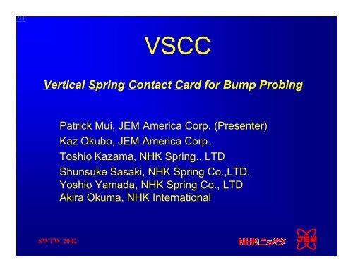
VSCC: Vertical Spring Contact Card for Bump Probing
VSCC: Vertical Spring Contact Card for Bump Probing
VSCC: Vertical Spring Contact Card for Bump Probing

Create successful ePaper yourself
Turn your PDF publications into a flip-book with our unique Google optimized e-Paper software.
<strong>VSCC</strong><br />
<strong>Vertical</strong> <strong>Spring</strong> <strong>Contact</strong> <strong>Card</strong> <strong>for</strong> <strong>Bump</strong> <strong>Probing</strong><br />
Patrick Mui, JEM America Corp. (Presenter)<br />
Kaz Okubo, JEM America Corp.<br />
Toshio Kazama, NHK <strong>Spring</strong>., LTD<br />
Shunsuke Sasaki, NHK <strong>Spring</strong> Co.,LTD.<br />
Yoshio Yamada, NHK <strong>Spring</strong> Co., LTD<br />
Akira Okuma, NHK International<br />
SWTW 2002
Outline<br />
? <strong>VSCC</strong> Concept<br />
? Electrical and Mechanical Data<br />
? Maintenance<br />
? Specifications<br />
? Roadmap<br />
? Summary<br />
SWTW 2002
<strong>Vertical</strong> <strong>Spring</strong> <strong>Contact</strong> <strong>Card</strong><br />
Features:<br />
? For probing area arrays (solder or Cu bumps).<br />
? Mechanically-isolated probes.<br />
? Stable alignment and planarity.<br />
? Replaceable probes and head.<br />
? No floating probes.<br />
? Low, linear probe <strong>for</strong>ce.<br />
? Two different tip shapes.<br />
SWTW 2002
<strong>Vertical</strong> <strong>Spring</strong> <strong>Contact</strong> <strong>Card</strong><br />
<strong>Bump</strong> side<br />
<strong>Contact</strong> to <strong>Bump</strong><br />
( Flat or pointed<br />
Tip)<br />
<strong>Contact</strong> to Interposer<br />
( Conical Tip)<br />
SWTW 2002<br />
MLO \ MLC side
SWTW 2002<br />
Probe Head Aerial View<br />
Probe Head with PCB
VSC Configuration<br />
(Wire Trans<strong>for</strong>mer Type)<br />
Stiffener<br />
Wire Trans<strong>for</strong>mer<br />
Board<br />
Guide Plate<br />
<strong>Spring</strong> Pin<br />
SWTW 2002
VSC Configuration<br />
(Space Trans<strong>for</strong>mer with MLO/MLC)<br />
Stiffener<br />
Board<br />
Spacer<br />
Solder Reflow<br />
MLO / MLC<br />
Guide Plate<br />
<strong>Spring</strong> Pin<br />
SWTW 2002
Current Rating under room temp<br />
For 150um pitch pin<br />
<strong>Spring</strong> Force [gf]<br />
after 60sec current loaded<br />
5<br />
4<br />
3<br />
2<br />
1<br />
0<br />
Rated current under room temperature<br />
SCP10-2510BP<br />
Change rate 80%<br />
Rated current result<br />
: 0.6A<br />
SCP10-2510<br />
0 0.1 0.2 0.3 0.4 0.5 0.6 0.7 0.8 0.9 1<br />
Current [A]• @• i60sec loading• j<br />
SWTW 2002
Dielectric Breakdown Voltage<br />
Voltage Source<br />
V<br />
A<br />
SCP14-3010<br />
SCP12-2510<br />
SCP10-2510<br />
0.2mm Pitch<br />
0.175mm<br />
Pitch<br />
0.15mm Pitch<br />
AC 400V (<strong>for</strong> 1 minute)<br />
AC 400V (<strong>for</strong> 1 minute)<br />
AC 300V (<strong>for</strong> 1 minute)<br />
SWTW 2002
Impedance - S 11 Short Measurement<br />
Impedance<br />
6GHz<br />
1GHz<br />
10GHz<br />
Smith Chart<br />
Conductor Plate<br />
(Short Terminated)<br />
50M~ 10.05GHz<br />
Measured at 0.150mm pitch<br />
SWTW 2002
Inductance<br />
SPICE Equivalent Circuit Model Simulation<br />
by S-NAP Circuit Simulator<br />
DUT=SCP10-2510BP<br />
Inductance<br />
L [nH]<br />
3<br />
2<br />
1<br />
0<br />
0.71nH<br />
Pin Inductance<br />
0 1 2 3 4 5 6<br />
Frequency [GHz]<br />
SWTW 2002
Operating Frequency<br />
(Insertion Loss)<br />
Insertion Loss<br />
(S 21 Through Measurement )<br />
Frequency [GHz]<br />
DUT=SCP10-2510BP<br />
0<br />
0 2 4 6 8 10 12 14 16 18 20<br />
Insertion Loss [dB]<br />
-3<br />
-6<br />
-9<br />
?3dB<br />
P0.15 S1G1 GO05<br />
SG<br />
Pitch=0.15mm<br />
SWTW 2002
Signal Integrity<br />
(TDT Measurement)<br />
Voltage<br />
Voltage<br />
[V]<br />
[V]<br />
2.5 2.5<br />
2.0 2.0<br />
1.5 1.5<br />
1.0 1.0<br />
0.5<br />
Signal Delay (TDT Measured Data)<br />
Response at 50ps Rise Time<br />
Source<br />
Response :: SCP10-2510BP (SG)<br />
0.0 0.0<br />
700 700 800 800 900 900 1000 1100 1200 1300 1400 1500 1600 1700<br />
Time [ps]<br />
SWTW 2002<br />
Rise Time [ps]<br />
Source<br />
Response<br />
Delay [ps]<br />
50 58.6 20.8<br />
100 108.3 22.6<br />
200 208.4 24.7<br />
300 309.0 26.4<br />
400 406.9 28.6<br />
500 506.9 30.0
Force / Resistance - Travel Curve<br />
Average = 3.81gf @170um OD<br />
SCP10-2510<br />
DC Ressistance / <strong>Spring</strong> Force<br />
SCP10-2510<br />
<strong>Spring</strong> Force [gf]<br />
30<br />
25<br />
20<br />
15<br />
10<br />
5<br />
1500<br />
1250<br />
1000<br />
750<br />
500<br />
250<br />
DC Resistance [m-ohm]<br />
0<br />
0 100 200<br />
Travel [micro-m]<br />
0<br />
SWTW 2002
CRES vs Touchdowns<br />
Resistance<br />
[m? ]<br />
1000<br />
800<br />
600<br />
400<br />
200<br />
0<br />
Resistance Measurements<br />
Durable Test Travel : 100?m<br />
Resistance is Measured at 100?m Travel<br />
MAX<br />
AVE<br />
MIN<br />
100 1,000 10,000 100, 000 1,000,000<br />
Number of Touchdowns<br />
SWTW 2002
Solder <strong>Bump</strong> De<strong>for</strong>mation After <strong>Probing</strong><br />
• Temp.: 85 degree<br />
• O.D. : 170 um<br />
* <strong>Contact</strong> De<strong>for</strong>mation Diameter<br />
is measured on Xaxis<br />
Top View<br />
of Non-<strong>Contact</strong><br />
Solder <strong>Bump</strong><br />
First<br />
contact<br />
3 times<br />
contact<br />
6 times<br />
contact<br />
* * *<br />
SWTW 2002
Ball De<strong>for</strong>mation Measurement<br />
Temp.: 85 degree TD: 1 time OD: 170um<br />
1.77um<br />
35um<br />
Be<strong>for</strong>e <strong>Contact</strong><br />
After <strong>Contact</strong><br />
SWTW 2002
Probe Alignment at 85 o C<br />
DY µm<br />
40<br />
30<br />
20<br />
10<br />
0<br />
-10<br />
-20<br />
-30<br />
15µm<br />
✟<br />
Series1<br />
Series2<br />
Series3<br />
1000 TD<br />
Series4<br />
Series5<br />
300K TD<br />
Condition<br />
Number of probes: 40pins<br />
Number of DUT: Single<br />
-40<br />
-40 -20 0 20 40<br />
DX µ m<br />
SWTW 2002
Planarity<br />
20 um<br />
15 um<br />
10 um<br />
Planarity<br />
5 um<br />
0 um<br />
-5 um<br />
-10 um<br />
-15 um<br />
-20 um<br />
5µm<br />
SWTW 2002<br />
Condition<br />
Number of probes: 40pins<br />
Number of DUT: Single
Cleaning Procedure<br />
?Cleaning Sheet<br />
Lapping film with 1-µm grain size<br />
?Conditions<br />
? OD : 100 µm<br />
? Wiping action : 150 µm<br />
? Number Touchdowns : 5~ 10<br />
SWTW 2002
Tip Cleaning<br />
Number of Wipes<br />
Initial<br />
3K TDs 5 Times 10 Times 20 Times 30 Times<br />
SWTW 2002
Specifications<br />
? Alignment : ±15 um<br />
? Planarity : ±15 um<br />
? Minimum Pitch : 150 um<br />
? Material : P7, Steel<br />
? Tip Diameter : 75 -100 um<br />
? Tip Length : 250-300 20 um<br />
? <strong>Contact</strong> Resistance : less than 1 ohm<br />
? <strong>Contact</strong> Force : 4.1 - 6 g<br />
? Recommended OD : 170 - 200 um<br />
? Maximum Current : 500 mA<br />
? Temperature Range : 25 - 85 o C<br />
SWTW 2002
Road Map<br />
2000 2001 2002 2003<br />
2004<br />
PITCH<br />
200um<br />
150um<br />
Temp.<br />
85?<br />
150?<br />
Array size<br />
50 50 mm<br />
100 100 mm<br />
Max. Pin<br />
1,000 1,500 3000 8000<br />
2000<br />
2001<br />
2002<br />
2003<br />
2004<br />
SWTW 2002
Summary<br />
?New solution <strong>for</strong> area arrays.<br />
?Stable mechanical and electrical per<strong>for</strong>mance.<br />
?Very easy to repair.<br />
?Proven in production at multiple sites.<br />
SWTW 2002