CONDURIX - FAFNIR Gmbh
CONDURIX - FAFNIR Gmbh
CONDURIX - FAFNIR Gmbh

Create successful ePaper yourself
Turn your PDF publications into a flip-book with our unique Google optimized e-Paper software.
Technical Documentation<br />
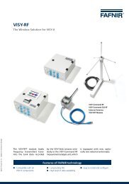
<strong>CONDURIX</strong><br />
The potentiometric level sensor<br />
Edition: 2012-09<br />
Version: 6<br />
Article no.: 207134<br />
<strong>FAFNIR</strong> GmbH • Bahrenfelder Str. 19 • 22765 Hamburg • Germany • Tel.: +49 / 40 / 39 82 07–0 • Fax: +49 / 40 / 390 63 39
Table of contents<br />
1 Field of application ................................................................................ 1<br />
2 Safety instructions ................................................................................. 2<br />
3 Design and function description ........................................................... 3<br />
4 Installation .............................................................................................. 5<br />
4.1 <strong>CONDURIX</strong> Mono (single rod) ............................................................................. 6<br />
4.2 <strong>CONDURIX</strong> DU (two rods) ................................................................................... 6<br />
4.3 <strong>CONDURIX</strong> MA (jacketed pipe) ........................................................................... 6<br />
5 Electrical connection .............................................................................. 7<br />
6 Configuration ......................................................................................... 9<br />
6.1 Measuring span at the level sensor ..................................................................... 9<br />
6.2 Current draw in failure mode ........................................................................... 10<br />
7 Maintenance ......................................................................................... 11<br />
7.1 Return shipment ............................................................................................... 11<br />
8 Technical data ....................................................................................... 12<br />
9 List of figures ........................................................................................ 13<br />
10 Appendix .............................................................................................. 14<br />
10.1 EC – Declaration of Conformity ........................................................................ 14<br />
10.2 EC-Type Examination Certificate ....................................................................... 15<br />
10.3 Instructions ...................................................................................................... 18<br />
© Copyright:<br />
Reproduction and translation only with the written consent of the company <strong>FAFNIR</strong> GmbH. The <strong>FAFNIR</strong><br />
GmbH reserves the right to carry out product alterations without prior notice.<br />
Table of contents II
1 Field of application<br />
The purpose of the <strong>CONDURIX</strong> level sensor is to provide continuous level gauging of electrically<br />
conductive liquids (> 1 μS/cm). During the measurement no insulating layer must<br />
be formed on the probe tube.<br />
The level sensor is available in lengths of 200 to 6,000 mm.<br />
With the “single-rod probe” model (<strong>CONDURIX</strong> Mono), the inside of the container must<br />
have a conductive surface (metal containers/downpipes). The “two-rod probe” model<br />
(<strong>CONDURIX</strong> DU) or “jacketed probe” model (<strong>CONDURIX</strong> MA) are both compatible with<br />
non-conductive containers.<br />
The standard sensors work by outputting the measured fill level as an analogue value in<br />
the range 4 to 20 mA.<br />
With the HART option, the configuration and retrieval of measured values by the digital<br />
HART protocol are supported, see<br />
• Technical Documentation for <strong>CONDURIX</strong> with HART protocol (English) – art. no.<br />
350044<br />
With the USB option, the measured values can be transferred directly to a PC and evaluated<br />
using the <strong>FAFNIR</strong> “USB Datalogger” software application, see<br />
• Technical Documentation for <strong>FAFNIR</strong> USB Datalogger (German) – art. no. 350012<br />
In conjunction with the standard level sensors, wetted parts are in stainless steel 1.4571,<br />
insulators are in PEEK (alternatively in PTFE). On request, the probe tubes are also available<br />
in Hastelloy, tantalum, titanium or stainless steel 1.4404.<br />
Page 1/20 Field of application
2 Safety instructions<br />
The purpose of the <strong>CONDURIX</strong> level sensor is to provide continuous level gauging of liquids.<br />
The level sensor must be used exclusively for this purpose. The manufacturer accepts<br />
no liability for any loss or damage arising from improper use.<br />
The level sensor has been developed, manufactured and tested in accordance with the<br />
latest good engineering practices and generally accepted safety standards. Nevertheless,<br />
hazards may arise from its use. For this reason, the following safety information must be<br />
observed:<br />
Do not change or modify the level sensor or add any equipment without the prior consent<br />
of the manufacturer. The installation, operation and maintenance of the level sensor<br />
must be carried out only by expert personnel. Equipment operators, set-up technicians<br />
and service technicians must comply with all applicable safety regulations. This also applies<br />
to any local safety regulations and accident prevention regulations which are not<br />
stated in these operating instructions.<br />
The safety instructions in this manual are labelled as follows:<br />
Failure to observe these safety instructions could result in a risk of accident<br />
or damage to the <strong>CONDURIX</strong> level sensor.<br />
Useful information designed to ensure continued and correct operation of<br />
the <strong>CONDURIX</strong> level sensor and to make your work easier.<br />
Safety instructions Page 2/20
3 Design and function description<br />
The design of the <strong>CONDURIX</strong> level sensor is illustrated in Figure 1 with the screw-in unit<br />
version as an example. Inside the sensor head (1) and concealed by the cap (2) are the<br />
protected terminals and configuration buttons. The electrical connection is established by<br />
means of an M16x1.5 screwed cable gland (3) and screw terminals or by an M12 plug-in<br />
connection. Earth connection (4) is required only in conjunction with the <strong>CONDURIX</strong><br />
Mono version (see section 5 Electrical connection). On the probe neck, there is either a<br />
screw-in unit (5) or a flange (not shown) for installing the probe in the container.<br />
Figure 1: The <strong>CONDURIX</strong> level sensor<br />
A current pulse generates a linear voltage drop (< 100 mV) on the probe tube (6) electrically<br />
insulated from tank potential. The voltages at the bottom end and top end of the<br />
tube are measured.<br />
As long as the probe tube is not immersed, it has no path to the tank potential. This state<br />
is detected by the signal processor, which outputs an “empty” signal. As soon as the<br />
probe tube is immersed, the voltage measured at the immersed tube end corresponds to<br />
tank potential and the voltage measured at the top end is added to the voltage drop<br />
along the non-immersed part of the probe tube.<br />
With the probe tube fully immersed, the voltages measured at the top and bottom ends<br />
of the tube are equal in respect of the potential reference point. The region in between is<br />
mostly linear, depending on the tank geometry and the distance between the tube end<br />
and tank bottom, which makes it possible to calculate the fill level from the ratio of the<br />
measured voltages.<br />
Page 3/20 Design and function description
The fill level is calculated from the ratio of the measured voltages by a microcontroller.<br />
The ratio of the two voltages also enables the orientation of the <strong>CONDURIX</strong> sensor to be<br />
detected, i.e. whether the sensor has been installed from top down or bottom up.<br />
The level sensor is fed from a 2-wire 4 to 20 mA interface and requires a voltage between<br />
8 and 30 V. The positions of the 4 mA and 20 mA points on the probe tube are freely<br />
adjustable (see chapter 6 Configuration). To prevent galvanic processes from occurring in<br />
the liquid, both the discharging and charging currents flow through a galvanically isolating<br />
transformer. The alternating voltage produced across the very low-resistance probe<br />
tube is in the 100 mV range.<br />
The table below shows the signal characteristics of the sensor depending on sensor orientation<br />
and measured value output setting (normal/inverted).<br />
Installation<br />
top down<br />
Installation<br />
bottom up<br />
Figure 2: Measured value output<br />
Measured value output<br />
normal<br />
Fill level “Empty” signal<br />
20 mA<br />
4 mA<br />
20 mA<br />
4 mA<br />
3.8 mA<br />
3.8 mA<br />
Measured value output<br />
inverted<br />
Fill level “Empty” signal<br />
4 mA<br />
20 mA<br />
4 mA<br />
20 mA<br />
20.5 mA<br />
20.5 mA<br />
Bottom up orientation: The 0 point is at the probe base<br />
Top down orientation: The 0 point is at the sensor head<br />
Normal measured value output: The 20 mA point is higher than the 4 mA point<br />
Inverted measured value output: The 20 mA point is lower than the 4 mA point<br />
Design and function description Page 4/20
4 Installation<br />
Measuring range Adjusting range 112<br />
All local safety and accident prevention regulations not expressly referred to<br />
herein must be observed.<br />
<strong>CONDURIX</strong> MA<br />
∅ 50<br />
8<br />
Figure 3: <strong>CONDURIX</strong> variants<br />
Cap, WAF 19<br />
removable<br />
Screwed<br />
cable gland M16x1.5<br />
Sensor<br />
head<br />
Earth<br />
connection<br />
Jacketed pipe<br />
Probe tube<br />
160<br />
Installation length<br />
<strong>CONDURIX</strong> Mono<br />
∅ 50<br />
Measuring range<br />
3<br />
Cap, WAF 19<br />
removable<br />
Screwed<br />
cable gland<br />
M16x1.5<br />
Sensor head<br />
Earth<br />
connection<br />
Screw-in<br />
unit R ¾ min.<br />
or flange<br />
Flange or<br />
screw-in unit R 2<br />
Probe tube<br />
∅ 6<br />
Counter electrode<br />
∅ 24<br />
<strong>CONDURIX</strong> DU<br />
∅ 50<br />
Level gauging with <strong>CONDURIX</strong> is possible only in electrically conductive liquids.<br />
The level sensor can also be fitted into the tank from underneath. The orientation<br />
is detected automatically.<br />
<strong>CONDURIX</strong> Mono: If the probe tube is immersed in the liquid only a short<br />
way, the linearity of the measurement is affected by the short distance between<br />
the probe tube and reference potential.<br />
Page 5/20 Installation<br />
Measuring range<br />
29<br />
160<br />
Installation length
4.1 <strong>CONDURIX</strong> Mono (single rod)<br />
With the single-rod probe, the tank acts as the counter electrode. For this reason, the<br />
material on the inside of the tank must be conductive and there must be good electrical<br />
contact between the tank and sensor head. For this purpose, the earth connection must<br />
be connected to the tank.<br />
4.2 <strong>CONDURIX</strong> DU (two rods)<br />
With the two-rod probe, the second rod acts as the counter electrode. As the distance<br />
from reference potential is constant, the measurement result is unaffected by the geometry<br />
of the tank. While the second rod also adds to the stability of the mechanical design,<br />
this does require a larger process connection for installation.<br />
4.3 <strong>CONDURIX</strong> MA (jacketed pipe)<br />
With the jacketed probe version, a pipe (coaxial in construction) surrounding the probe<br />
tube acts as the counter electrode. As the distance from reference potential is constant,<br />
the measurement result is unaffected by the geometry of the tank.<br />
The jacketed pipe also provides a shield against electrical interference and facilitates<br />
measurements in otherwise unfavourable measuring conditions.<br />
Installation Page 6/20
5 Electrical connection<br />
For the wiring of the level sensor, you need a two-core unshielded cable, which is terminated<br />
inside the sensor head of the level sensor.<br />
It is essential that the correct cross section be selected: the supply voltage at the level sensor<br />
must not fall below 8 V in the event of maximum current draw (21.5 mA).<br />
To connect the level sensor (see Figure 4):<br />
(1) Unscrew cap (1) using an open-ended spanner (WAF 19)<br />
(2) Loosen union nut (2) of screwed cable gland (3)<br />
5<br />
Figure 4: Connecting the <strong>CONDURIX</strong> level sensor<br />
(3) Feed two-core cable (4) through union nut (2) and fit screwed cable gland (3)<br />
and then retighten the union nut.<br />
(4) Connect two-core cable (4) to the screw terminals on the sensor head marked (+)<br />
and (–).<br />
Pinout of the M12 plug-in connection: Pin 1 = brown (+) Pin 3 = blue (-)<br />
(5) Screw on cap (1)<br />
Page 7/20 Electrical connection
The earth connection on the underside of the sensor head can be used for earthing or<br />
equipotential bonding.<br />
With the <strong>CONDURIX</strong> Mono, earth connection (5) must be connected to the<br />
electrically conductive tank.<br />
Protect the sensor head against the ingress of water. An external cable diameter<br />
of 5 to 10 mm ensures reliable sealing of the cable entry. Make sure<br />
that the cable gland is screwed tight, and close the cap firmly.<br />
During all installation operations, be aware that the negative terminal of the<br />
<strong>CONDURIX</strong> is internally connected to the housing. Therefore use only a galvanic<br />
isolated input of your control system (i.e. PLC) or use an external galvanic<br />
separator.<br />
Electrical connection Page 8/20
6 Configuration<br />
6.1 Measuring span at the level sensor<br />
To enable configuration of the 4 mA and 20 mA points at the <strong>CONDURIX</strong> level sensor,<br />
two buttons and an LED (light emitting diode) are provided near the terminals inside the<br />
sensor head.<br />
By default, the level sensor is set to maximum span with 4 mA at the probe base and<br />
20 mA at the sensor head. The measuring span is configurable for adaptation to the tank<br />
concerned. However, the minimum distance between both points must be at least<br />
10 mm. If this minimum distance is not observed, the display direction of the level sensor<br />
will be reversed automatically. The measured value would then be inverted.<br />
Measuring span configuration (see Figure 5):<br />
Figure 5: Measuring span configuration<br />
(1) Unscrew cap (1) using an open-ended spanner (WAF 19).<br />
(2) Press and hold 4 mA button (2) or 20 mA button (3) for at least 3 seconds.<br />
The level sensor is now in configuration mode. Green LED (4) “Cal/Err” flashes. The current<br />
draw of the level sensor is 12 mA. If no button is pressed again, the level sensor remains<br />
in configuration mode for 20 seconds before reverting to measuring mode and<br />
discarding any changes.<br />
In configuration mode, the 4 mA or 20 mA point, or both reference points, can be modified<br />
in any order.<br />
Page 9/20 Configuration
To define a reference point while the sensor is in configuration mode<br />
• briefly press the 4 mA button (2) (1-2 seconds) to define a current draw of 4 mA<br />
for the present immersed position of the sensor.<br />
• briefly press the 20 mA button (3) (1-2 seconds) to define a current draw of 20<br />
mA for the present immersed position of the sensor.<br />
When the 4 mA button is pressed, the LED goes out for 5 seconds. When the 20 mA button<br />
is pressed, the LED lights up permanently for 5 seconds. The sensor then remains in<br />
configuration mode for a further 15 seconds before storing the change and reverting to<br />
measuring mode.<br />
The new configuration will not be adopted by the level sensor until it has<br />
switched from configuration mode to measuring mode automatically (LED<br />
goes out). The level sensor must, therefore, not be disconnected from the<br />
power supply until this time.<br />
6.2 Current draw in failure mode<br />
If a malfunction is preventing the level sensor from detecting levels correctly, the sensor<br />
will enter failure mode after a short time. Failure mode signalling conforms to the NA-<br />
MUR NE43 recommendation. The failure current is set by default to 21.5 mA but this value<br />
can also be set to 3.6 mA.<br />
Configuration of current draw in failure mode (see Figure 5):<br />
(1) Unscrew cap (1) using an open-ended spanner.<br />
(2) Press and hold both the 4 mA button (2) and the 20 mA button (3) simultaneously<br />
for at least 3 seconds.<br />
Green LED (4) “Cal/Err” flashes rapidly. The current draw of the level sensor is 16 mA.<br />
After 5 seconds, the LED stops flashing and then indicates the selected failure current<br />
draw for 2.5 seconds. If the LED lights up permanently, the failure current is 21.5 mA; if<br />
the LED goes out, the failure current is 3.6 mA. If no button is pressed again, the level<br />
sensor remains in failure mode for a further 2.5 seconds before reverting to measuring<br />
mode and discarding the change.<br />
• To set a current draw of 3.6 mA during the 10-second dwell period in failure<br />
mode, briefly press the 4 mA button (2) (1–2 seconds).<br />
• To set a current draw of 21.5 mA during the 10-second dwell period in failure<br />
mode, briefly press the 20 mA button (3) (1–2 seconds).<br />
Configuration Page 10/20
The new configuration will not be adopted by the level sensor until it has<br />
switched from configuration mode to measuring mode automatically (LED<br />
goes out). The level sensor must, therefore, not be disconnected from the<br />
power supply until this time.<br />
(3) Screw on cap (1).<br />
If, during operation, the level sensor detects that the level cannot be output<br />
correctly due to an insufficient supply voltage, it enters failure mode and<br />
sets current draw to 3.6 mA (regardless of any failure current settings).<br />
7 Maintenance<br />
7.1 Return shipment<br />
Before returning any <strong>FAFNIR</strong> equipment the returned goods authorization by the <strong>FAFNIR</strong><br />
customer care is required. Please contact your account manager or the customer care to<br />
get the instructions for the return of goods.<br />
The return of <strong>FAFNIR</strong> equipment is possible only with authorization by the<br />
<strong>FAFNIR</strong> customer care.<br />
Page 11/20 Maintenance
8 Technical data<br />
Electrical connection<br />
Power supply<br />
Output signal<br />
“Empty” signal<br />
Failure signal<br />
Two-line terminal<br />
8 to 30 V DC<br />
4 to 20 mA<br />
3.8 mA or 20.5 mA<br />
21.5 mA or 3.6 mA<br />
Process connection Screw-in unit (standard R 3/4)<br />
Flange on request<br />
For material, see probe tube<br />
Sensor head Height above screw-in unit/flange 160 mm<br />
Diameter 50 mm<br />
Index of protection IP 68<br />
Material: stainless steel<br />
Cable diameter 5 to 10 mm<br />
Temperature –40 to +85 °C<br />
Probe tube Length 200 to 6,000 mm<br />
Diameter of single rod 6 mm (standard)<br />
Standard material: 1.4571<br />
Optional material: tantalum, titanium, Hastelloy,<br />
or 1.4404<br />
Measuring range freely configurable (> 10 mm)<br />
Seal PEEK (alternatively PTFE)<br />
Accuracy<br />
Digital component<br />
Linearity better than ±1 mm or ±1 %<br />
Resolution better than 0.1 %<br />
Analogue component Temperature drift better than ±0.01 %/K<br />
Resolution better than 0.5 μA<br />
Process temperature -40 °C … +150 °C<br />
Process pressure 150 bar at 20 °C, 25 bar at 150 °C<br />
Process conductivity > 1 μS/cm<br />
Technical data Page 12/20
9 List of figures<br />
Figure 1: The <strong>CONDURIX</strong> level sensor .............................................................................. 3<br />
Figure 2: Measured value output ..................................................................................... 4<br />
Figure 3: <strong>CONDURIX</strong> variants .......................................................................................... 5<br />
Figure 4: Connecting the <strong>CONDURIX</strong> level sensor ............................................................ 7<br />
Figure 5: Measuring span configuration .......................................................................... 9<br />
Page 13/20 List of figures
Appendix<br />
10 Appendix<br />
10.1 EC – Declaration of Conformity<br />
Appendix Page 14/20
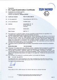
10.2 EC-Type Examination Certificate<br />
Page 15/20 Appendix
Appendix Page 16/20
Page 17/20 Appendix
10.3 Instructions<br />
Level Gauge <strong>CONDURIX</strong> Ex ... Edition: 04.2011<br />
I Range of application<br />
The intrinsically safe equipment <strong>CONDURIX</strong> Ex ... is used for the continuous measurement of liquid<br />
levels. The level sensor operates only in electrically conductive liquids (conductivity ≥ 1 μS/cm). If the<br />
level sensor is inserted into a tank with non-conducting wall, the sensor must be equipped with a<br />
backplate electrode, e. g. the <strong>CONDURIX</strong> Ex MA ...<br />
II Standards<br />
See EC-Type Examination Certificate.<br />
III Instructions for safe ...<br />
III.a ... use<br />
The approval applies to the following types respectively device versions:<br />
<strong>CONDURIX</strong> Ex ... Mono<br />
<strong>CONDURIX</strong> Ex ... DU<br />
<strong>CONDURIX</strong> Ex ... MA<br />
<strong>CONDURIX</strong> Ex E HY<br />
<strong>CONDURIX</strong> Ex E ... V<br />
<strong>CONDURIX</strong> Ex ... extern<br />
<strong>CONDURIX</strong> Ex ... extern Steck<br />
<strong>CONDURIX</strong> Ex ... M12<br />
All level sensors <strong>CONDURIX</strong> Ex ... can be produced with plastic insulation (e. g. PEEK, PTFE) or ceramic<br />
with O ring seal.<br />
In order to vary the height the version <strong>CONDURIX</strong> Ex E ... V is provided. The process connection is<br />
done via a cutting ring coupling.<br />
With limited mounting space the electronics may be installed in an external enclosure (<strong>CONDURIX</strong> Ex<br />
... external). The connection to the sensor can be done via a fixed cable or via a connector (e. g.<br />
LEMO).<br />
The level sensor <strong>CONDURIX</strong> Ex … HART has in addition to the current signal a digital communication<br />
capability supported by the HART protocol. This allows a highly flexible programming and operation<br />
of the level sensor.<br />
III.b ... mounting<br />
Screw-in unit:<br />
Seal the threads of the screw in unit with a suitable sealing material, screw it into the existing<br />
socket and tighten it.<br />
In the case of installation with a cutting ring coupling, it is no longer possible to alter the position<br />
of the level sensor after the union nut has been tightened.<br />
Flange:<br />
The probe tube is permanently fixed to the flange, which means that the installation length cannot<br />
be altered. Seal the flange with a suitable sealing and fix it with flange bolts or nuts.<br />
If the level sensor is supplied without process connection, the installer is responsible for compliance<br />
with the EX requirements.<br />
Appendix Page 18/20
III.c ... installation<br />
The level sensor has a two-pole electrical connector. Via this two pole connector, the sensor is powered<br />
and the level signal is forwarded simultaneously to the parent transducer.<br />
All wiring operations must solely be carried out with the power disconnected. The special<br />
EN-regulations including EN 60079-14 and local installation regulations must be observed. The wiring<br />
from the sensor to the transducer shall be carried out using a two-wire cable (preferably blue).<br />
The terminals + and - of the sensor must be connected to the same terminals of the transducer.<br />
The PA terminal is located at the bottom of the probe head and must securely be attached to the<br />
tank.<br />
III.d ... putting into service<br />
Before putting into service, all devices must be checked of right connection and fitting. The power<br />
supply, as well of the upstream devices, must be checked.<br />
III.e ... maintenance, overhaul and repair<br />
The device is maintenance-free. In case of a defect, please send back the level sensor to the manufacturer<br />
<strong>FAFNIR</strong>.<br />
IV Equipment marking<br />
1 Manufacturer: <strong>FAFNIR</strong> GmbH, Hamburg<br />
2 Type designation: <strong>CONDURIX</strong> Ex …<br />
3 Serial Number: Ser. N°: …<br />
4 Certificate Number: TÜV 11 ATEX 078858<br />
5 Ex marking:<br />
II 1 G Ex ia IIC/IIB T6 Ga<br />
II 1/2 G Ex ia IIC/IIB T6 Ga/Gb<br />
Different marking for the level sensor <strong>CONDURIX</strong> Ex E HY<br />
6 Temperature: Zone 0:<br />
II 1 G Ex ia IIB T6 Ga<br />
II 1/2 G Ex ia IIB T6 Ga/Gb<br />
-20 °C … +45 °C (T6), +60 °C (T5, T4)<br />
Zone 0/1: -40 °C … +45 °C (T6), +60 °C (T5), +85 °C (T4)<br />
7 CE marking: 0044<br />
8 Electrical Data: Ui Ii ≤ 30 V<br />
≤ 200 mA<br />
Pi ≤ 1 W<br />
Ci ≤ 5 nF<br />
Li ≤ 30 μH<br />
Page 19/20 Appendix
V Technical data<br />
The level sensor is connected to a 4 ... 20 mA interface, which provides the auxiliary energy simultaneously.<br />
The connection is via the + and - terminals. The sealing of the cable is given by a cable entry<br />
or by a conduit system. Also an M12 plug-in connection can be used for the interface, pin 1 (+) and<br />
pin 3 (-).<br />
Power supply: U = 8 V … 30 V d.c.<br />
The following safety-related values are defined with:<br />
Input voltage: U i ≤ 30 V<br />
Input current: I i ≤ 200 mA<br />
Input power: P i ≤ 1 W<br />
The externally effective capacitance and inductance are:<br />
Internal capacitance: C i ≤ 5 nF<br />
Internal inductance: L i ≤ 30 μH<br />
When used in potentially explosive atmospheres, the maximum temperatures depending on the<br />
temperature classes and categories can be found in the table.<br />
Temperature class T medium resp. T probe tube T ambient resp. T probe head<br />
Category 1 (level sensor entirely erected in Zone 0)<br />
T6 -20 °C … +45 °C<br />
T5, T4, T3, T2, T1 -20 °C … +60 °C<br />
Category 1/2 (probe tube erected in Zone 0, sensor head erected in Zone 1)<br />
T6 -40 °C ... +45 °C<br />
T5 -20 °C … +60 °C -40 °C ... +60 °C<br />
T4, T3, T2, T1 -40 °C ... +85 °C<br />
Category 2 (level sensor entirely erected in Zone 1)<br />
T6 -40 °C … +85 °C -40 °C ... +45 °C<br />
T5 -40 °C … +100 °C -40 °C ... +60 °C<br />
T4 -40 °C … +135 °C<br />
T3 -40 °C … +200 °C<br />
T2 -40 °C … +300 °C<br />
T1 -40 °C … +450 °C<br />
-40 °C ... +85 °C<br />
If the probe tube is operated at higher liquid temperatures as listed in the table, it must be ensured<br />
through appropriate measures that at no point of the probe, the temperature (T ambient ) will<br />
be exceeded according to the relevant temperature class.<br />
General Note: Zone 0 is given only under atmospheric conditions (see EN 60079-0):<br />
Temperature range: -20 °C … +60 °C<br />
Pressure range: 0,8 bar … 1,1 bar<br />
Oxidants: Air (oxygen content of about 21 %)<br />
Appendix Page 20/20
<strong>FAFNIR</strong> GmbH<br />
Bahrenfelder Str. 19<br />
22765 Hamburg<br />
Tel.: +49 / 40 / 39 82 07–0<br />
Fax: +49 / 40 / 390 63 39<br />
E-Mail: info@fafnir.de<br />
Web: www.fafnir.de