Hose and Flexible Tubing (MS-01-180;rev_6;en-US) - Swagelok
Hose and Flexible Tubing (MS-01-180;rev_6;en-US) - Swagelok
Hose and Flexible Tubing (MS-01-180;rev_6;en-US) - Swagelok

You also want an ePaper? Increase the reach of your titles
YUMPU automatically turns print PDFs into web optimized ePapers that Google loves.
www.swagelok.com<br />
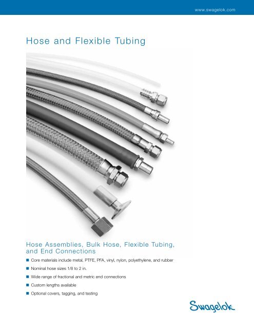
<strong>Hose</strong> <strong>and</strong> <strong>Flexible</strong> <strong>Tubing</strong><br />
<strong>Hose</strong> Assemblies, Bulk <strong>Hose</strong>, <strong>Flexible</strong> <strong>Tubing</strong>,<br />
<strong>and</strong> End Connections<br />
■ Core materials include metal, PTFE, PFA, vinyl, nylon, polyethyl<strong>en</strong>e, <strong>and</strong> rubber<br />
■ Nominal hose sizes 1/8 to 2 in.<br />
■ Wide range of fractional <strong>and</strong> metric <strong>en</strong>d connections<br />
■ Custom l<strong>en</strong>gths available<br />
■ Optional covers, tagging, <strong>and</strong> testing
2 <strong>Hose</strong> <strong>and</strong> <strong>Flexible</strong> <strong>Tubing</strong><br />
Cont<strong>en</strong>ts<br />
<strong>Swagelok</strong>® <strong>Hose</strong> <strong>and</strong> <strong>Flexible</strong><br />
<strong>Tubing</strong> Nom<strong>en</strong>clature, 4<br />
<strong>Swagelok</strong> <strong>Hose</strong> <strong>and</strong> <strong>Flexible</strong><br />
<strong>Tubing</strong> Selection Guide, 6<br />
Metal <strong>Hose</strong><br />
FM Series Metal <strong>Hose</strong>, 10<br />
Fluoropolymer <strong>Hose</strong><br />
T Series PTFE <strong>Hose</strong>, 30<br />
Considerations for Selecting a<br />
<strong>Hose</strong> Assembly Solution, 8<br />
FJ Series Metal <strong>Hose</strong>, 16<br />
B Series PTFE <strong>Hose</strong>, 36<br />
<strong>Swagelok</strong> <strong>Hose</strong> <strong>and</strong> <strong>Flexible</strong><br />
<strong>Tubing</strong> Installation <strong>and</strong> Use<br />
Guide, 9<br />
FL Series Metal <strong>Hose</strong>, 21<br />
X Series PTFE <strong>Hose</strong>, 38<br />
Metal <strong>Flexible</strong> <strong>Tubing</strong><br />
S Series PTFE <strong>Hose</strong>, 40<br />
CT Series Convoluted Metal<br />
<strong>Tubing</strong>, 25<br />
C Series PTFE <strong>Hose</strong>, 42<br />
N Series PTFE <strong>Hose</strong>, 44
Cont<strong>en</strong>ts<br />
<strong>Hose</strong> <strong>and</strong> <strong>Flexible</strong> <strong>Tubing</strong> 3<br />
W Series PTFE <strong>Hose</strong>, 46<br />
Nylon <strong>Hose</strong><br />
Options<br />
NG Series Nylon <strong>Hose</strong>, 67<br />
Covers, 83<br />
F Series PTFE <strong>Hose</strong>, 48<br />
Testing, 83<br />
7R <strong>and</strong> 8R Series Nylon <strong>Hose</strong>, 71<br />
Tags, 84<br />
U Series PFA <strong>Hose</strong>, 50<br />
PFA <strong>Tubing</strong><br />
7N <strong>and</strong> 8N Series Nylon <strong>Hose</strong>, 72<br />
Approvals, 84<br />
Tools <strong>and</strong> Accessories<br />
Cutting Tools for <strong>Hose</strong><br />
<strong>and</strong> Soft <strong>Tubing</strong>, 85<br />
PFA Series PFA <strong>Tubing</strong>, 61<br />
Polyethyl<strong>en</strong>e <strong>Hose</strong><br />
Assembly Tools for Nylon,<br />
Polyethyl<strong>en</strong>e, <strong>and</strong> Rubber <strong>Hose</strong>,<br />
86<br />
Vinyl <strong>Tubing</strong><br />
LT Series Vinyl <strong>Tubing</strong>, 63<br />
7P Series Polyethyl<strong>en</strong>e <strong>Hose</strong>, 77<br />
Rubber <strong>Hose</strong><br />
Accessories for H<strong>and</strong> <strong>and</strong> Power<br />
Swagers, 86<br />
Pushers <strong>and</strong> Swage Dies for<br />
Nylon <strong>and</strong> Polyethyl<strong>en</strong>e<br />
<strong>Hose</strong>, 87<br />
PB Series Rubber <strong>Hose</strong>, 79<br />
<strong>Hose</strong> Connectors<br />
HC Series—End Connections for<br />
Soft <strong>Tubing</strong> <strong>and</strong> <strong>Hose</strong>, 64<br />
Dim<strong>en</strong>sions, in inches (millimeters), are for refer<strong>en</strong>ce only<br />
<strong>and</strong> are subject to change. Dim<strong>en</strong>sions are shown with<br />
<strong>Swagelok</strong> nuts finger-tight. For <strong>Swagelok</strong> nut dim<strong>en</strong>sions, see<br />
the <strong>Swagelok</strong> Gaugeable Tube Fittings <strong>and</strong> Adapter Fittings<br />
catalog, <strong>MS</strong>‐<strong>01</strong>‐140.
4 <strong>Hose</strong> <strong>and</strong> <strong>Flexible</strong> <strong>Tubing</strong><br />
<strong>Swagelok</strong> <strong>Hose</strong> <strong>and</strong> <strong>Flexible</strong> <strong>Tubing</strong> Nom<strong>en</strong>clature<br />
<strong>Hose</strong><br />
A multiple-layered flexible conduit<br />
through which fluid is conveyed from<br />
one point to another.<br />
Nominal <strong>Hose</strong> Size<br />
An approximation of the hose inside<br />
diameter.<br />
<strong>Flexible</strong> <strong>Tubing</strong><br />
A single-layered flexible conduit<br />
through which fluid is conveyed from<br />
one point to another.<br />
B<strong>en</strong>d Radius<br />
The radius of the b<strong>en</strong>t section of<br />
hose, measured to the c<strong>en</strong>ter line or<br />
inside of the curved section.<br />
Minimum Dynamic B<strong>en</strong>d Radius<br />
The smallest b<strong>en</strong>d radius that a hose<br />
is rated to perform in a dynamic<br />
application.<br />
Minimum Static B<strong>en</strong>d Radius<br />
The smallest b<strong>en</strong>d radius that a<br />
hose is rated to perform in a static<br />
application.<br />
Flexibility<br />
The relative ease or difficulty of<br />
b<strong>en</strong>ding a nonpressurized hose or<br />
tubing assembly.<br />
Burst Pressure<br />
The pressure at which leakage<br />
occurs wh<strong>en</strong> exposed to a laboratory<br />
burst test.<br />
Static Dissipation<br />
The ability of a material to conduct<br />
an electrical charge to ground. Select<br />
<strong>Swagelok</strong> hoses are constructed with<br />
carbon black-filled nylon, PTFE, or PFA<br />
core material for static dissipation. For<br />
quick refer<strong>en</strong>ce in this catalog, these<br />
hoses are indicated with the omega<br />
symbol () in the hose description.<br />
SWAGELOK<br />
Conductivity<br />
The ability of a material to transmit<br />
or conduct an electrical charge.<br />
<strong>Swagelok</strong> hoses constructed with a<br />
metallic braid layer have the pot<strong>en</strong>tial<br />
to be conductive hoses. For quick<br />
refer<strong>en</strong>ce in this catalog, these hoses<br />
are indicated with the symbol (M) in the<br />
hose description.<br />
Inside<br />
b<strong>en</strong>d radius<br />
Permeation<br />
The movem<strong>en</strong>t of a liquid, gas, or<br />
vapor through a solid. All materials<br />
are permeable to a degree <strong>and</strong><br />
should be tested for application<br />
compatibility prior to installation.<br />
C<strong>en</strong>ter line<br />
b<strong>en</strong>d radius<br />
SWAGELOK<br />
Dynamic Application<br />
An application in which the hose<br />
flexes or changes position.<br />
SWAGELOK<br />
Static Application<br />
An application in which the hose is<br />
stationary <strong>and</strong> does not move in any<br />
plane.<br />
Splices<br />
Splices consist of a connector<br />
fitting <strong>and</strong> crimp collars that join two<br />
l<strong>en</strong>gths of hose to form assemblies.<br />
Splices may be required to obtain<br />
longer hose l<strong>en</strong>gths of fluoropolymer<br />
hose (B, X, S, C, N, W, F, <strong>and</strong> U<br />
series), as noted in the Ordering<br />
Information for each series.<br />
Splice dim<strong>en</strong>sions shown in the<br />
table at right are for refer<strong>en</strong>ce<br />
only <strong>and</strong> are subject to change.<br />
Additional overall hose l<strong>en</strong>gth may<br />
be needed to comp<strong>en</strong>sate for the<br />
effect of splices on hose minimum<br />
b<strong>en</strong>d radius. For more information,<br />
contact your authorized <strong>Swagelok</strong><br />
sales <strong>and</strong> service repres<strong>en</strong>tative.<br />
Nominal<br />
<strong>Hose</strong> Size<br />
in. (mm)<br />
A<br />
Maximum<br />
A<br />
Dim<strong>en</strong>sions, in. (mm)<br />
Minimum<br />
Inside<br />
Diameter<br />
Maximum<br />
Outside<br />
Dim<strong>en</strong>sion<br />
1/8 (3.2) 2.60 (66.0) 0.070 (1.7) 0.55 (14.0)<br />
1/4 (6.4) 2.60 (66.0) 0.16 (4.0) 0.59 (15.0)<br />
3/8 (9.6) 3.30 (83.8) 0.26 (6.6) 0.82 (20.8)<br />
1/2 (12.7) 3.70 (94.0) 0.34 (8.6) 1.04 (26.4)<br />
3/4 (19.0) 4.80 (122) 0.54 (13.7) 1.35 (34.3)<br />
1 (25.4) 4.60 (117) 0.78 (19.8) 1.75 (44.4)<br />
1 1/2 (38.1) 5.60 (142) 1.24 (31.4) 2.20 (55.9)<br />
2 (50.8) 6.90 (175) 1.68 (42.6) 2.74 (69.6)
<strong>Hose</strong> <strong>and</strong> <strong>Flexible</strong> <strong>Tubing</strong> 5<br />
<strong>Swagelok</strong> <strong>Hose</strong> <strong>and</strong> <strong>Flexible</strong> <strong>Tubing</strong> Nom<strong>en</strong>clature<br />
Maximum Outside Dim<strong>en</strong>sion<br />
The largest nominal outside<br />
dim<strong>en</strong>sion of the hose assembly.<br />
Live L<strong>en</strong>gth (L)<br />
The flexible l<strong>en</strong>gth of a<br />
hose or tubing assembly.<br />
End Connection<br />
The fitting that is assembled<br />
onto each <strong>en</strong>d of the hose to<br />
provide a means of installation<br />
into a fluid system.<br />
Live L<strong>en</strong>gth (L)<br />
Overall L<strong>en</strong>gth (OAL)<br />
A<br />
Braid (Overbraid)<br />
A flexible, wov<strong>en</strong><br />
reinforcem<strong>en</strong>t.<br />
Overall L<strong>en</strong>gth (OAL)<br />
The distance from<br />
<strong>en</strong>d to <strong>en</strong>d for a hose<br />
or tubing assembly.<br />
End Connection L<strong>en</strong>gth (A)<br />
Overall l<strong>en</strong>gth of the <strong>en</strong>d<br />
connection.<br />
Core<br />
The innermost material of the hose<br />
that carries the system media, oft<strong>en</strong><br />
referred to as the wetted surface.<br />
Spring Guard<br />
A helical metal spring used to<br />
protect the hose from abrasion,<br />
overb<strong>en</strong>ding, <strong>and</strong> kinking.<br />
Reinforcem<strong>en</strong>t<br />
Material used to<br />
reinforce the core<br />
<strong>and</strong> increase its<br />
pressure-containing<br />
capacity.<br />
Cover<br />
The outermost material of a hose, used to<br />
protect the reinforcem<strong>en</strong>t <strong>and</strong> core from<br />
<strong>en</strong>vironm<strong>en</strong>tal conditions <strong>and</strong> wear.<br />
Minimum Inside Diameter<br />
The smallest inside diameter of<br />
the hose prior to assembly.
6 <strong>Hose</strong> <strong>and</strong> <strong>Flexible</strong> <strong>Tubing</strong><br />
<strong>Swagelok</strong> <strong>Hose</strong> <strong>and</strong> <strong>Flexible</strong> <strong>Tubing</strong> Selection Guide<br />
See individual hose series sections for additional technical information.<br />
Materials of Construction<br />
Series<br />
Core Reinforcem<strong>en</strong>t Cover<br />
Metal <strong>Hose</strong><br />
Page<br />
FM Convoluted 316L SS 316L SS braid — 10<br />
FJ<br />
Convoluted 316L SS<br />
304 SS braid st<strong>and</strong>ard;<br />
316L SS braid available<br />
— 16<br />
FL Convoluted 316L SS 321 SS braid — 21<br />
Metal <strong>Flexible</strong> <strong>Tubing</strong><br />
CT Convoluted 321 SS — — 25<br />
Fluoropolymer <strong>Hose</strong><br />
T Smooth-bore PTFE➀ 304 SS braid st<strong>and</strong>ard; 316L SS<br />
<strong>and</strong> alloy 400 braid available<br />
— 30<br />
B Smooth-bore PTFE 304 SS braid — 36<br />
X Smooth-bore PTFE➀ Fiber braid with 304 SS braid — 38<br />
S Smooth-bore PTFE➀ Fiber braid with 304 SS braid Silicone 40<br />
C Convoluted PTFE➀ 300 series SS braid<br />
N<br />
W<br />
Convoluted,<br />
carbon black-filled PTFE<br />
Smooth-bore,<br />
carbon black-filled PTFE<br />
Insulating wrap<br />
<strong>and</strong> aramid fiber braid<br />
Fiber braid with insulating wrap<br />
<strong>and</strong> 304 SS braid<br />
No cover st<strong>and</strong>ard;<br />
silicone cover available<br />
42<br />
— 44<br />
Silicone 46<br />
F Smooth-bore PTFE➀ Fiber braid — 48<br />
U Smooth-bore PFA➁ 302 SS braid Silicone 50<br />
PFA <strong>Tubing</strong><br />
PFA Smooth-bore PFA — — 61<br />
Vinyl <strong>Tubing</strong><br />
LT Smooth-bore clear vinyl — — 63<br />
Nylon <strong>Hose</strong><br />
NG<br />
Smooth-bore,<br />
static dissipative nylon<br />
Fiber braid<br />
Perforated black polyurethane<br />
with blue stripe<br />
67<br />
7R Smooth-bore nylon Fiber braid Perforated black polyurethane 71<br />
8R Smooth-bore nylon Fiber braid Perforated black polyurethane 71<br />
7N<br />
8N<br />
Smooth-bore,<br />
nonconductive nylon<br />
Smooth-bore,<br />
nonconductive nylon<br />
Fiber braid Nonperforated orange polyurethane 72<br />
Fiber braid Nonperforated orange polyurethane 72<br />
Polyethyl<strong>en</strong>e <strong>Hose</strong><br />
7P Smooth-bore polyethyl<strong>en</strong>e Fiber braid Nonperforated blue polyurethane 77<br />
Rubber <strong>Hose</strong><br />
PB Smooth-bore Buna N Synthetic fiber braid<br />
➀ Carbon black-filled PTFE core is available for applications that require static dissipation.<br />
➁ Carbon black-filled PFA core is available for applications that require static dissipation.<br />
Blue Buna N<br />
(other colors available)<br />
79
<strong>Swagelok</strong> <strong>Hose</strong> <strong>and</strong> <strong>Flexible</strong> <strong>Tubing</strong> Selection Guide<br />
See individual hose series sections for additional technical information.<br />
<strong>Hose</strong> <strong>and</strong> <strong>Flexible</strong> <strong>Tubing</strong> 7<br />
Series<br />
Nominal <strong>Hose</strong> Size, in.<br />
Working Pressure at 70°F (20°C), psig (bar)<br />
1/8 3/16 1/4 3/8 1/2 3/4 1 1 1/4 1 1/2 2<br />
FM — —<br />
FJ — —<br />
FL — —<br />
CT — —<br />
T — —<br />
B<br />
3000<br />
(206)<br />
X — —<br />
S<br />
3000<br />
(206)<br />
3100<br />
(213)<br />
1600<br />
(110)<br />
1500<br />
(103)<br />
100<br />
(6.8)<br />
3000➀<br />
(206)<br />
2000<br />
(137)<br />
1470<br />
(1<strong>01</strong>)<br />
—<br />
25<br />
(1.7)<br />
2500<br />
(172)<br />
<strong>180</strong>0<br />
(124)<br />
1110<br />
(76.4)<br />
1200<br />
(82.6)<br />
25<br />
(1.7)<br />
2000<br />
(137)<br />
Metal <strong>Hose</strong><br />
1500<br />
(103)<br />
860<br />
(59.2)<br />
1200<br />
(82.6)<br />
680<br />
(46.8)<br />
950<br />
(65.4)<br />
680<br />
(46.8)<br />
900<br />
(62.0)<br />
520<br />
(35.8)<br />
500<br />
(34.4)<br />
450<br />
(31.0)<br />
— — — — —<br />
Metal <strong>Flexible</strong> <strong>Tubing</strong><br />
25<br />
(1.7)<br />
25<br />
(1.7)<br />
Fluoropolymer <strong>Hose</strong><br />
1500<br />
(103)<br />
1000<br />
(68.9)<br />
—<br />
25<br />
(1.7)<br />
—<br />
— — —<br />
Temperature<br />
Range<br />
°F (°C) Page<br />
−325 to 850<br />
(−200 to 454)<br />
−325 to 800<br />
(−200 to 426)<br />
−325 to 850<br />
(−200 to 454)<br />
70 to 1000<br />
(20 to 537)<br />
— — — — — — — — — 36<br />
—<br />
3500<br />
(241)<br />
3500<br />
(241)<br />
3000<br />
(206)<br />
3000<br />
(206)<br />
C — — — —<br />
N — — —<br />
W — — —<br />
F — —<br />
800<br />
(55.1)<br />
1250<br />
(86.1)<br />
750<br />
(51.6)<br />
650<br />
(44.7)<br />
U — — — —<br />
PFA<br />
LT<br />
275<br />
(18.9)<br />
40<br />
(2.7)<br />
—<br />
30<br />
(2.0)<br />
NG — —<br />
7R — —<br />
8R — —<br />
7N — —<br />
275<br />
(18.9)<br />
25<br />
(1.7)<br />
5000<br />
(344)<br />
2750<br />
(189)<br />
5000<br />
(344)<br />
2750<br />
(189)<br />
<strong>180</strong><br />
(12.4)<br />
15<br />
(1.0)<br />
5000<br />
(344)<br />
2250<br />
(155)<br />
4000<br />
(275)<br />
2250<br />
(155)<br />
<strong>180</strong>0<br />
(124)<br />
<strong>180</strong>0<br />
(124)<br />
1500<br />
(103)<br />
750<br />
(51.6)<br />
750<br />
(51.6)<br />
450<br />
(31.0)<br />
300<br />
(20.6)<br />
125<br />
(8.6)<br />
10<br />
(0.68)<br />
1250<br />
(86.1)<br />
1250<br />
(86.1)<br />
1100<br />
(75.7)<br />
375<br />
(25.8)<br />
500<br />
(34.4)<br />
325<br />
(22.3)<br />
300<br />
(20.6)<br />
1000<br />
(68.9)<br />
1000<br />
(68.9)<br />
750<br />
(51.6)<br />
— — — 38<br />
— — —<br />
−65 to 450➁<br />
40<br />
(−53 to 230)<br />
—<br />
700<br />
(48.2)<br />
525<br />
(36.1)<br />
— — — — 44<br />
— — — — 46<br />
— — — — 48<br />
250<br />
(17.2)<br />
PFA <strong>Tubing</strong><br />
83<br />
(5.7)<br />
61<br />
(4.2)<br />
Vinyl <strong>Tubing</strong><br />
—<br />
200<br />
(13.7)<br />
150<br />
(10.3)<br />
— — —<br />
— — — — —<br />
Nylon <strong>Hose</strong><br />
— — — — — —<br />
2000<br />
(137)<br />
3500<br />
(241)<br />
2000<br />
(137)<br />
8N — — — — —<br />
7P — —<br />
PB — —<br />
2750<br />
(189)<br />
350<br />
(24.1)<br />
2250<br />
(155)<br />
300<br />
(20.6)<br />
2000<br />
(137)<br />
300<br />
(20.6)<br />
— — — — —<br />
2250<br />
(155)<br />
2000<br />
(137)<br />
— — —<br />
— — — — —<br />
2250<br />
(155)<br />
Polyethyl<strong>en</strong>e <strong>Hose</strong><br />
1500<br />
(103)<br />
— — — —<br />
1500<br />
(103)<br />
Rubber <strong>Hose</strong><br />
300<br />
(20.6)<br />
➀ T series hose with alloy 400 braid is rated to 1500 psig (103 bar).<br />
300<br />
(20.6)<br />
— — —<br />
— — —<br />
➁ C series hose is rated from −20 to 340°F (−28 to 171°C) in the 1 1/2 <strong>and</strong> 2 in. nominal hose sizes.<br />
➂ PB series hose is rated from −20 to 200°F (−28 to 93°C) in the 1 in. nominal hose size.<br />
–65 to 400<br />
(–53 to 204)<br />
70 to 400<br />
(20 to 204)<br />
−40 to 165<br />
(−40 to 73)<br />
−40 to 150<br />
(−40 to 65)<br />
−40 to 200<br />
(−40 to 93)<br />
−40 to 200<br />
(−40 to 93)<br />
−40 to 200<br />
(−40 to 93)<br />
−40 to 200<br />
(−40 to 93)<br />
−10 to 150<br />
(−23 to 65)<br />
−40 to 200➂<br />
(−40 to 93)<br />
10<br />
16<br />
21<br />
25<br />
30<br />
42<br />
50<br />
61<br />
63<br />
67<br />
71<br />
71<br />
72<br />
72<br />
77<br />
79
8 <strong>Hose</strong> <strong>and</strong> <strong>Flexible</strong> <strong>Tubing</strong><br />
Considerations for Selecting a <strong>Hose</strong> Assembly Solution<br />
Temperature<br />
Id<strong>en</strong>tify the minimum <strong>and</strong> maximum temperatures the hose<br />
assembly will be exposed to with regard to the system media<br />
<strong>and</strong> the <strong>en</strong>vironm<strong>en</strong>t.<br />
Pressure<br />
Id<strong>en</strong>tify the minimum <strong>and</strong> maximum pressures (or vacuum)<br />
within <strong>and</strong> outside the hose assembly.<br />
Material<br />
Id<strong>en</strong>tify the system media <strong>and</strong> the <strong>en</strong>vironm<strong>en</strong>t to which the<br />
hose assembly will be exposed. This will help determine<br />
the materials of construction best suited to the application<br />
dem<strong>and</strong>s <strong>and</strong> whether the hose requires a static dissipative<br />
core.<br />
Movem<strong>en</strong>t<br />
Confirm whether the hose assembly will be installed<br />
in dynamic applications as this will require differ<strong>en</strong>t<br />
considerations than a static application.<br />
L<strong>en</strong>gth<br />
Determine the most likely route for installation of the hose,<br />
<strong>and</strong> use this to id<strong>en</strong>tify l<strong>en</strong>gth requirem<strong>en</strong>ts.<br />
Ori<strong>en</strong>tation<br />
Clarify space constraint concerns. <strong>Hose</strong> assemblies<br />
with elbows <strong>and</strong> union ball joints may help resolve space<br />
constraint issues.<br />
Desired Flow<br />
Consider desired flow. <strong>Hose</strong> connection size, core tube<br />
construction, <strong>and</strong> routed installation may impact flow.<br />
Drainability<br />
Consider core construction as this will impact drainability.<br />
Test Reports<br />
Id<strong>en</strong>tify the need for docum<strong>en</strong>tation in the form of test<br />
reports.<br />
Special Testing<br />
Many applications may require testing to requirem<strong>en</strong>ts<br />
differ<strong>en</strong>t from the production tests listed. For example, metal<br />
hose assemblies undergo an inboard helium leak test to a<br />
maximum leak rate of 1 3 10 –5 std cm 3 /s. If your application<br />
uses liquid at a positive pressure, you may request an<br />
additional hydrostatic proof test.<br />
Special Marking<br />
Discuss special marking requirem<strong>en</strong>ts; there are differ<strong>en</strong>t<br />
options available to readily id<strong>en</strong>tify hose assemblies.<br />
Docum<strong>en</strong>tation <strong>and</strong> Regulatory Requirem<strong>en</strong>ts<br />
Id<strong>en</strong>tify the need for special regulatory approvals or<br />
docum<strong>en</strong>tation.<br />
Additional Protection <strong>and</strong> Covers<br />
Id<strong>en</strong>tify whether covers are necessary for additional<br />
protection of the hose assemblies or surrounding systems.<br />
Additional Considerations<br />
■ Use of hose <strong>and</strong> tubing within applications <strong>and</strong> h<strong>and</strong>ling<br />
practices will affect how it performs over time. Catalog<br />
performance claims such as burst pressure, working<br />
pressure, static dissipation, moisture cont<strong>en</strong>t, permeation<br />
rates, <strong>and</strong> cycle life apply to never-used products. For this<br />
reason, system maint<strong>en</strong>ance <strong>and</strong> replacem<strong>en</strong>t schedules<br />
should be considered.<br />
Cautions<br />
Nylon, PFA, polyethyl<strong>en</strong>e, PTFE, <strong>and</strong> rubber are<br />
permeable materials. Gases, vapors, <strong>and</strong> liquids may<br />
migrate through cores of these materials. The rate of<br />
permeation is affected by many application-specific<br />
variables.<br />
Cleanliness<br />
Id<strong>en</strong>tify the need for cleanliness. Ease of cleaning the<br />
internal surfaces of the hose, as well as maintaining outside<br />
cleanliness may be of concern.<br />
End Connection<br />
Id<strong>en</strong>tify the type of <strong>en</strong>d connections which are most<br />
compatible with the system requirem<strong>en</strong>ts. End connections<br />
differ with regard to materials of construction <strong>and</strong> pressure<br />
ratings.<br />
Nonperforated covers may blister in gas service.<br />
Thermal cycling of any nonmetal hose may affect<br />
its ability to maintain a positive seal. Testing should<br />
be performed to verify suitability in actual operating<br />
conditions.<br />
All equipm<strong>en</strong>t must be properly grounded to allow<br />
static dissipation <strong>and</strong> help to p<strong>rev</strong><strong>en</strong>t static sparking.<br />
Nonconductive hoses can be conduits for electricity if<br />
they contain conductive fluids. Verify the conductive<br />
properties of the system media prior to use.
<strong>Swagelok</strong> <strong>Hose</strong> <strong>and</strong> <strong>Flexible</strong> <strong>Tubing</strong> Installation <strong>and</strong> Use Guide<br />
<strong>Hose</strong> <strong>and</strong> <strong>Flexible</strong> <strong>Tubing</strong> 9<br />
Inspection<br />
Establish an inspection schedule based on system<br />
application <strong>and</strong> replacem<strong>en</strong>t history.<br />
Electrostatic Discharge<br />
Static electricity can be g<strong>en</strong>erated by fluid passing through<br />
the hose. Select hose with suffici<strong>en</strong>t conductivity to ground<br />
the static electric charge <strong>and</strong> allow static dissipation. If<br />
static electricity g<strong>en</strong>eration is possible within an application,<br />
choose static dissipative hose <strong>and</strong> properly ground to earth.<br />
Vibration<br />
Evaluate amount of system vibration wh<strong>en</strong> selecting hose.<br />
Metal hose may not be appropriate for systems with constant<br />
or severe vibration.<br />
L<strong>en</strong>gth<br />
Take into consideration hose movem<strong>en</strong>t, system<br />
pressurization, <strong>and</strong> thermal expansion wh<strong>en</strong> determining<br />
hose l<strong>en</strong>gth. Installing hose that does not have suffici<strong>en</strong>t<br />
l<strong>en</strong>gth to accommodate these factors may reduce hose life.<br />
Minimum B<strong>en</strong>d Radius<br />
Follow minimum b<strong>en</strong>d radius requirem<strong>en</strong>ts for your hose.<br />
Installing hose with smaller b<strong>en</strong>ds may kink hose <strong>and</strong> reduce<br />
hose life.<br />
Motion Absorption<br />
Distribute movem<strong>en</strong>t <strong>and</strong> p<strong>rev</strong><strong>en</strong>t b<strong>en</strong>ds smaller than the<br />
hose’s minimum b<strong>en</strong>d radius by providing suffici<strong>en</strong>t hose<br />
l<strong>en</strong>gth.<br />
Correct<br />
Machine Tolerance<br />
Allow for changes in l<strong>en</strong>gth resulting from machine motion<br />
<strong>and</strong> tolerances.<br />
Correct<br />
Incorrect<br />
Incorrect<br />
Minimum<br />
straight<br />
l<strong>en</strong>gth<br />
B<strong>en</strong>d<br />
radius<br />
System Pressure Changes<br />
Allow suffici<strong>en</strong>t hose l<strong>en</strong>gth to accommodate changing<br />
system pressures. Do not connect high- <strong>and</strong> low pressure<br />
hoses.<br />
motion absorption<br />
L<strong>en</strong>gth<strong>en</strong><br />
Correct<br />
Incorrect<br />
<strong>Hose</strong> rupture or leakage may result from b<strong>en</strong>ding too close to<br />
the hose/fitting connection.<br />
Short<strong>en</strong><br />
B<strong>en</strong>ding in One Plane<br />
Avoid twisting the hose by b<strong>en</strong>ding it in one plane only. For a<br />
machine pressure changes<br />
compound b<strong>en</strong>d, use multiple hose pieces or other isolation<br />
methods.<br />
Correct<br />
Incorrect<br />
<strong>Hose</strong> Strain<br />
Elbows <strong>and</strong> adapters can be used to relieve hose strain.<br />
minimum b<strong>en</strong>d radius<br />
system pressure changes<br />
minimum b<strong>en</strong>d radius<br />
Correct<br />
Incorrect<br />
Correct<br />
Incorrect<br />
For additional information, see SAE J1273, Recomm<strong>en</strong>ded<br />
Practices for Hydraulic <strong>Hose</strong> Assemblies.<br />
Images on this page reprinted with permission from SAE J1273.<br />
© 2009 SAE International.<br />
b<strong>en</strong>ding in one plane r2
METAL<br />
10 <strong>Hose</strong> <strong>and</strong> <strong>Flexible</strong> <strong>Tubing</strong><br />
FM Series Metal <strong>Hose</strong><br />
Features<br />
■ All-metal hose promotes corrosion resistance.<br />
■ 316L stainless steel annular convoluted core.<br />
■ Size range of 1/4 through 2 in. <strong>and</strong> working pressures from<br />
vacuum to 3100 psig (213 bar).<br />
■ Single braid layer of 316L stainless steel promotes hose<br />
pressure containm<strong>en</strong>t <strong>and</strong> exhibits strong performance in<br />
dynamic cycling applications (M).<br />
■ End connections welded in accordance with ASME Boiler<br />
<strong>and</strong> Pressure Vessel Code Section IX.<br />
■ Commonly used in high-temperature vacuum applications<br />
<strong>and</strong> medium-pressure corrosive <strong>en</strong>vironm<strong>en</strong>ts, or where<br />
permeation is undesirable.<br />
■ St<strong>and</strong>ard <strong>and</strong> custom assemblies available.<br />
■ Options include hose covers, hose tags, <strong>and</strong> additional<br />
helium leak testing. See page 83 for details.<br />
316L SS braid 316L SS core Weld<br />
316 SS <strong>en</strong>d<br />
connections<br />
Technical Data<br />
Nominal<br />
<strong>Hose</strong> Size<br />
in. (mm)<br />
Inside<br />
Diameter<br />
in. (mm)<br />
Outside<br />
Diameter<br />
in. (mm)<br />
Minimum C<strong>en</strong>ter Line<br />
B<strong>en</strong>d Radius<br />
in. (cm)<br />
Static Dynamic<br />
Temperature<br />
Range<br />
°F (°C)<br />
Working<br />
Pressure at<br />
–325 to 100°F<br />
(–200 to 37°C)<br />
Vacuum to ...<br />
psig (bar)<br />
Burst<br />
Pressure at<br />
70°F (20°C)<br />
psig (bar)<br />
Bulk<br />
<strong>Hose</strong><br />
Weight<br />
lb/ft (kg/m)<br />
1/4 (6.4) 0.28 (7.1) 0.53 (13.5) 2.25 (5.72) 10.0 (25.4)<br />
3100 (213) 12 400 (854) 0.33 (0.49)<br />
3/8 (9.7) 0.42 (10.6) 0.69 (17.5) 3.00 (7.62) 12.0 (30.5) 2000 (137) 8 000 (551) 0.29 (0.43)<br />
1/2 (12.7) 0.53 (13.5) 0.85 (21.6) 4.50 (11.4) 16.0 (40.6) <strong>180</strong>0 (124) 7 200 (496) 0.45 (0.67)<br />
3/4 (19.0) 0.80 (20.3) 1.15 (29.1) 6.00 (15.2) 17.0 (43.2) –325 to 850 1500 (103) 6 000 (413) 0.62 (0.92)<br />
1 (25.4) 1.03 (26.0) 1.45 (36.9) 6.75 (17.1) 20.0 (50.8) (–200 to 454) 1200 (82.6) 4 800 (330) 0.77 (1.15)<br />
1 1/4 (31.8) 1.30 (33.0) 1.75 (44.5) 4.50 (11.4) 23.0 (58.4) 950 (65.4) 3 800 (261) 1.05 (1.56)<br />
1 1/2 (38.1) 1.53 (38.9) 2.02 (51.3) 5.25 (13.3) 26.0 (66.0) 900 (62.0) 3 600 (248) 1.18 (1.76)<br />
2 (50.8) 2.05 (52.1) 2.57 (65.3) 6.75 (17.1) 32.0 (81.3) 500 (34.4) 2 000 (137) 1.66 (2.47)<br />
Pressure-Temperature Ratings<br />
Ratings are based on ASME Code for Pressure Piping, B31.1 Power Piping, <strong>and</strong> ASME Boiler <strong>and</strong> Pressure Vessel Code.<br />
Nominal <strong>Hose</strong> Size, in. 1/4 3/8 1/2 3/4 1 1 1/4 1 1/2 2<br />
Temperature, °F (°C)<br />
Working Pressure, vacuum to ... psig (bar)<br />
–325 (–200) to 100 (37)<br />
200 (93)<br />
300 (148)<br />
400 (204)<br />
500 (260)<br />
600 (315)<br />
700 (371)<br />
800 (426)<br />
850 (454)<br />
3100 (213)<br />
2604 (179)<br />
2356 (162)<br />
2170 (149)<br />
2<strong>01</strong>5 (138)<br />
1922 (132)<br />
1829 (126)<br />
1767 (121)<br />
1736 (119)<br />
2000 (137)<br />
1680 (115)<br />
1520 (104)<br />
1400 (96.4)<br />
1300 (89.5)<br />
1240 (85.4)<br />
1<strong>180</strong> (81.3)<br />
1140 (78.5)<br />
1120 (77.1)<br />
<strong>180</strong>0 (124)<br />
1512 (104)<br />
1368 (94.2)<br />
1260 (86.8)<br />
1170 (80.6)<br />
1116 (76.8)<br />
1062 (73.1)<br />
1026 (70.6)<br />
1008 (69.4)<br />
1500 (103)<br />
1260 (86.8)<br />
1140 (78.5)<br />
1050 (72.3)<br />
975 (67.1)<br />
930 (64.0)<br />
885 (60.9)<br />
855 (58.9)<br />
840 (57.8)<br />
1200 (82.6)<br />
1008 (69.4)<br />
912 (62.8)<br />
840 (57.8)<br />
780 (53.7)<br />
744 (51.2)<br />
708 (47.8)<br />
684 (47.1)<br />
672 (46.3)<br />
950 (65.4)<br />
798 (54.9)<br />
722 (49.7)<br />
665 (45.8)<br />
618 (42.5)<br />
589 (40.5)<br />
561 (38.6)<br />
542 (37.3)<br />
532 (36.6)<br />
900 (62.0)<br />
756 (52.0)<br />
684 (47.1)<br />
630 (43.4)<br />
585 (40.3)<br />
558 (38.4)<br />
531 (36.5)<br />
513 (35.3)<br />
504 (34.7)<br />
500 (34.4)<br />
420 (28.9)<br />
380 (26.1)<br />
350 (24.1)<br />
325 (22.3)<br />
310 (21.3)<br />
295 (20.3)<br />
285 (19.6)<br />
280 (19.2)
<strong>Hose</strong> <strong>and</strong> <strong>Flexible</strong> <strong>Tubing</strong> 11<br />
FM Series Metal <strong>Hose</strong><br />
Testing<br />
Every <strong>Swagelok</strong> FM series hose<br />
assembly is inboard helium leak tested<br />
to a maximum leak rate of 1 3 10 –5<br />
std cm 3 /s.<br />
For additional testing, see Testing,<br />
page 83.<br />
Cleaning <strong>and</strong> Packaging<br />
<strong>Swagelok</strong> FM series hose compon<strong>en</strong>ts<br />
are cleaned in accordance with<br />
<strong>Swagelok</strong> St<strong>and</strong>ard Cleaning <strong>and</strong><br />
Packaging (SC‐10), <strong>MS</strong>‐06‐62. Each<br />
hose is bagged individually <strong>and</strong> boxed;<br />
longer hoses are coiled, bagged, <strong>and</strong><br />
boxed.<br />
Do not subject flexible metal<br />
hose to pressure surges, shock,<br />
or pulsations, where the peak<br />
pressure is greater than 50 % of<br />
the working pressure rating.<br />
METAL<br />
Ordering Information <strong>and</strong> Dim<strong>en</strong>sions<br />
St<strong>and</strong>ard L<strong>en</strong>gth <strong>Hose</strong> Assemblies<br />
Select an ordering number.<br />
L<br />
OAL<br />
<strong>Swagelok</strong> Tube Fitting to Male NPT End Connection<br />
Nominal<br />
<strong>Hose</strong><br />
Size<br />
in.<br />
Tube<br />
Fitting<br />
Size<br />
in.<br />
NPT<br />
Size<br />
in.<br />
1/4 1/4 1/4<br />
3/8 3/8 3/8<br />
1/2 1/2 1/2<br />
3/4 3/4 3/4<br />
1 1 1<br />
Dim<strong>en</strong>sions<br />
Overall<br />
L<strong>en</strong>gth<br />
OAL<br />
in. (cm)<br />
Ordering<br />
Number<br />
Live<br />
L<strong>en</strong>gth<br />
L<br />
in. (cm)<br />
Minimum<br />
Inside<br />
Diameter<br />
in. (mm)<br />
12.0 (30.5) SS-FM4SL4PM4-12 8.26 (21.0) 0.19<br />
36.0 (91.4) SS-FM4SL4PM4-36 32.3 (82.0) (4.8)<br />
18.0 (45.7) SS-FM6SL6PM6-18 14.2 (36.1) 0.28<br />
36.0 (91.4) SS-FM6SL6PM6-36 32.2 (81.8) (7.1)<br />
18.0 (45.7) SS-FM8SL8PM8-18 13.6 (34.5) 0.41<br />
48.0 (122) SS-FM8SL8PM8-48 43.6 (111) (10.4)<br />
18.0 (45.7) SS-FM12SL12PM12-18 13.4 (34.0) 0.66<br />
48.0 (122) SS-FM12SL12PM12-48 43.4 (110) (16.0)<br />
24.0 (61.0) SS-FM16SL16PM16-24 18.8 (47.8) 0.88<br />
60.0 (152) SS-FM16SL16PM16-60 54.8 (139) (22.4)<br />
Maximum<br />
Outside<br />
Dim<strong>en</strong>sion<br />
in. (mm)<br />
0.95 (24.1)<br />
1.09 (27.7)<br />
1.23 (31.3)<br />
1.74 (44.2)<br />
2.03 (51.6)<br />
<strong>Swagelok</strong> Tube Fitting End Connections<br />
Nominal<br />
<strong>Hose</strong><br />
Size<br />
in.<br />
Tube<br />
Fitting<br />
Size<br />
in.<br />
1/4 1/4<br />
3/8 3/8<br />
1/2 1/2<br />
3/4 3/4<br />
1 1<br />
Dim<strong>en</strong>sions<br />
Overall<br />
L<strong>en</strong>gth<br />
OAL<br />
in. (cm)<br />
Ordering<br />
Number<br />
Live<br />
L<strong>en</strong>gth<br />
L<br />
in. (cm)<br />
Minimum<br />
Inside<br />
Diameter<br />
in. (mm)<br />
12.0 (30.5) SS-FM4SL4SL4-12 8.12 (20.6) 0.19<br />
36.0 (91.4) SS-FM4SL4SL4-36 32.1 (81.5) (4.8)<br />
18.0 (45.7) SS-FM6SL6SL6-18 14.0 (35.6) 0.28<br />
36.0 (91.4) SS-FM6SL6SL6-36 32.0 (81.3) (7.1)<br />
18.0 (45.7) SS-FM8SL8SL8-18 13.5 (34.3) 0.41<br />
48.0 (122) SS-FM8SL8SL8-48 43.5 (110) (10.4)<br />
18.0 (45.7) SS-FM12SL12SL12-18 13.3 (33.8) 0.66<br />
48.0 (122) SS-FM12SL12SL12-48 43.3 (110) (16.0)<br />
24.0 (61.0) SS-FM16SL16SL16-24 18.7 (47.5) 0.88<br />
60.0 (152) SS-FM16SL16SL16-60 54.7 (139) (22.4)<br />
Maximum<br />
Outside<br />
Dim<strong>en</strong>sion<br />
in. (mm)<br />
0.95 (24.1)<br />
1.09 (27.7)<br />
1.23 (31.3)<br />
1.74 (44.2)<br />
2.03 (51.6)<br />
See next page for more hose assemblies.
12 <strong>Hose</strong> <strong>and</strong> <strong>Flexible</strong> <strong>Tubing</strong><br />
FM Series Metal <strong>Hose</strong><br />
<strong>Swagelok</strong> Tube Adapter End Connections<br />
METAL<br />
Nominal<br />
<strong>Hose</strong><br />
Size<br />
in.<br />
Tube<br />
Adapter<br />
Size<br />
in.<br />
Overall<br />
L<strong>en</strong>gth<br />
OAL<br />
in. (cm)<br />
Ordering<br />
Number<br />
Live<br />
L<strong>en</strong>gth<br />
L<br />
in. (cm)<br />
12.0 (30.5) SS-FM4TA4TA4-12 8.48 (21.5)<br />
Dim<strong>en</strong>sions<br />
Minimum<br />
Inside<br />
Diameter<br />
in. (mm)<br />
Maximum<br />
Outside<br />
Dim<strong>en</strong>sion<br />
in. (mm)<br />
1/4 1/4<br />
24.0 (61.0) SS-FM4TA4TA4-24 20.5 (52.1)<br />
36.0 (91.4) SS-FM4TA4TA4-36 32.5 (82.6)<br />
0.16<br />
(4.1)<br />
0.75<br />
(19.0)<br />
A<br />
48.0 (122) SS-FM4TA4TA4-48 44.5 (113)<br />
Ordering Information<br />
Custom <strong>Hose</strong> Assemblies<br />
Build a hose assembly ordering number by combining the designators in the sequ<strong>en</strong>ce shown below.<br />
Typical Ordering Number<br />
1 2 3 4 4 5 6 5 6<br />
S S - F M 4 T A 4 P M 4 - 2 8 F or 7 1 C M - F<br />
in. cm<br />
1 Material<br />
End Connections<br />
SS = 316 stainless steel<br />
2 <strong>Hose</strong><br />
FM = FM series metal hose<br />
3 Nominal <strong>Hose</strong> Size, in.<br />
4 = 1/4 16 = 1<br />
6 = 3/8 20 = 1 1/4<br />
8 = 1/2 24 = 1 1/2<br />
12 = 3/4 32 = 2<br />
4 End Connections<br />
See End Connection Designator<br />
column in tables on next page.<br />
Add designators in <strong>rev</strong>erse<br />
alphanumeric order.<br />
5 Overall L<strong>en</strong>gth<br />
Inches or c<strong>en</strong>timeters, in whole<br />
numbers. Include CM as shown for<br />
c<strong>en</strong>timeter l<strong>en</strong>gths.<br />
6 Options<br />
For multiple options, add designators in<br />
alphanumeric order with a dash betwe<strong>en</strong><br />
each designator. For hose l<strong>en</strong>gths<br />
specified in c<strong>en</strong>timeters, insert a dash as<br />
shown prior to the first option designator.<br />
CRN = Lanyard tag with CRN<br />
F = Fire jacket<br />
F1 = Thermosleeve<br />
H7 =Helium leak test (1 10 −7 std<br />
cm 3 /s)<br />
N3 = Nitrog<strong>en</strong> pressure test<br />
S =302 SS spring guard, hosel<strong>en</strong>gth<br />
(1/4, 3/8, <strong>and</strong> 1/2 in.<br />
sizes only)<br />
T = Lanyard tag<br />
T2 = Two lanyard tags<br />
W = Hydrostatic test<br />
Specify text for tags. See <strong>Hose</strong> Tag<br />
Text table, page 84.<br />
See page 83 for detailed descriptions<br />
of options.
FM Series Metal <strong>Hose</strong><br />
End Connections<br />
<strong>Hose</strong> <strong>and</strong> <strong>Flexible</strong> <strong>Tubing</strong> 13<br />
<strong>Swagelok</strong> Tube Adapters<br />
A<br />
Tube<br />
Adapter<br />
Size<br />
Nominal<br />
<strong>Hose</strong> Size<br />
Designator<br />
Dim<strong>en</strong>sions, in. (mm)<br />
End<br />
Connection<br />
Designator<br />
A<br />
Dim<strong>en</strong>sions<br />
Minimum<br />
Inside<br />
Diameter<br />
Maximum<br />
Outside<br />
Dim<strong>en</strong>sion<br />
1/4 4 TA4 1.76 (44.7) 0.16 (4.1) 0.75 (19.0)<br />
3/8 6 TA6 1.82 (46.2) 0.27 (6.9) 0.93 (23.6)<br />
1/2 8 TA8 2.22 (56.4) 0.37 (9.4) 1.05 (26.7)<br />
3/4 12 TA12 2.35 (59.7) 0.58 (14.7) 1.38 (35.1)<br />
1 16 TA16 2.69 (68.3) 0.80 (20.3) 1.69 (42.9)<br />
Dim<strong>en</strong>sions, mm (in.)<br />
6 4 TM6 44.4 (1.75) 4.1 (0.16) 19.0 (0.75)<br />
10 6 TM10 47.0 (1.85) 7.1 (0.28) 23.5 (0.93)<br />
12 8 TM12 57.2 (2.25) 8.9 (0.35) 26.7 (1.05)<br />
METAL<br />
<strong>Swagelok</strong> Tube Fittings<br />
A<br />
Cap Weld Style—<br />
1 in. <strong>and</strong> Under<br />
A<br />
Manual Weld Style—<br />
Over 1 in.<br />
Dim<strong>en</strong>sions<br />
Tube<br />
Fitting<br />
Size<br />
Nominal<br />
<strong>Hose</strong> Size<br />
Designator<br />
End<br />
Connection<br />
Designator A<br />
Minimum<br />
Inside<br />
Diameter<br />
Maximum<br />
Outside<br />
Dim<strong>en</strong>sion<br />
Dim<strong>en</strong>sions, in. (mm)<br />
1/4 4 SL4 1.94 (49.3) 0.19 (4.8) 0.95 (24.1)<br />
3/8<br />
4 SL6 2.00 (50.8)<br />
0.95 (24.1)<br />
0.28 (7.1)<br />
6 SL6 2.02 (51.3) 1.09 (27.7)<br />
1/2 8 SL8 2.24 (56.9) 0.41 (10.4) 1.23 (31.3)<br />
5/8 8 SL10 2.27 (57.7) 0.50 (12.7) 0.95 (24.1)<br />
3/4 12 SL12 2.35 (59.7) 0.63 (16.0) 1.74 (44.2)<br />
1 16 SL16 2.64 (67.1) 0.88 (22.4) 2.03 (51.6)<br />
1 1/4➀ 20 SL20 4.04 (103) 1.09 (27.7) 2.23 (58.9)<br />
1 1/2➀ 24 SL24 4.75 (121) 1.34 (34.0) 2.61 (66.3)<br />
2➀ 32 SL32 5.72 (145) 1.88 (47.8) 3.48 (88.4)<br />
Dim<strong>en</strong>sions, mm (in.)<br />
6 4 SM6 30.2 (1.19) 4.8 (0.19) 20.6 (0.81)<br />
8 4 SM8 50.3 (1.98) 6.4 (0.25) 20.6 (0.81)<br />
10 6 SM10 51.6 (2.03) 7.9 (0.31) 27.9 (1.10)<br />
12 8 SM12 59.7 (2.35) 9.7 (0.38) 31.3 (1.23)<br />
➀ Furnished with silver-plated front ferrule <strong>and</strong> uncoated back ferrule which are required for performance<br />
above 450˚F (232˚C).<br />
Rotatable Male<br />
VCR® Metal Gasket<br />
Face Seal Fittings<br />
A<br />
Dim<strong>en</strong>sions, in. (mm)<br />
VCR<br />
Size<br />
in.<br />
Nominal<br />
<strong>Hose</strong> Size<br />
Designator<br />
End<br />
Connection<br />
Designator A<br />
Minimum<br />
Inside<br />
Diameter<br />
Maximum<br />
Outside<br />
Dim<strong>en</strong>sion<br />
1/4 4 RM4 2.60 (66.0) 0.18 (4.6) 0.73 (18.4)<br />
1/2 8 RM8 2.83 (71.9) 0.40 (10.2) 1.09 (27.7)<br />
3/4 12 RM12 4.19 (106) 0.65 (16.5) 1.52 (38.7)<br />
1 16 RM16 4.80 (122) 0.87 (22.1) 1.89 (47.9)<br />
See next page for more <strong>en</strong>d connections.
14 <strong>Hose</strong> <strong>and</strong> <strong>Flexible</strong> <strong>Tubing</strong><br />
FM Series Metal <strong>Hose</strong><br />
METAL<br />
Rotatable Female<br />
VCR Metal Gasket<br />
Face Seal Fittings<br />
A<br />
Dim<strong>en</strong>sions, in. (mm)<br />
VCR<br />
Size<br />
in.<br />
Nominal<br />
<strong>Hose</strong> Size<br />
Designator<br />
End<br />
Connection<br />
Designator A<br />
Minimum<br />
Inside<br />
Diameter<br />
Maximum<br />
Outside<br />
Dim<strong>en</strong>sion<br />
1/4 4 RF4 2.00 (50.8) 0.18 (4.6) 0.87 (22.1)<br />
1/2 8 RF8 2.16 (54.9) 0.40 (10.2) 1.23 (31.3)<br />
3/4 12 RF12 4.15 (105) 0.65 (16.5) 1.74 (44.2)<br />
1 16 RF16 4.76 (121) 0.87 (22.1) 2.03 (51.6)<br />
Female VCO® O-Ring<br />
Face Seal Fittings<br />
A<br />
VCO<br />
Size<br />
in.<br />
Nominal<br />
<strong>Hose</strong> Size<br />
Designator<br />
End<br />
Connection<br />
Designator<br />
A<br />
Dim<strong>en</strong>sions, in. (mm)<br />
Minimum<br />
Inside<br />
Diameter<br />
Maximum<br />
Outside<br />
Dim<strong>en</strong>sion<br />
1/4 4 VF4 2.00 (50.8) 0.18 (4.6) 0.80 (20.3)<br />
1/2 8 VF8 2.14 (54.4) 0.40 (10.2) 1.16 (29.5)<br />
SAE 37° (JIC) Female<br />
Swivel<br />
A<br />
Dim<strong>en</strong>sions, in. (mm)<br />
Swivel<br />
Size<br />
in.<br />
Nominal<br />
<strong>Hose</strong> Size<br />
Designator<br />
End<br />
Connection<br />
Designator A<br />
Minimum<br />
Inside<br />
Diameter<br />
Maximum<br />
Outside<br />
Dim<strong>en</strong>sion<br />
1/4 4 AS4 1.87 (47.5) 0.17 (4.3) 0.94 (23.9)<br />
3/8 6 AS6 1.97 (50.0) 0.28 (7.1) 1.09 (27.7)<br />
1/2 8 AS8 2.15 (54.6) 0.42 (10.7) 1.23 (31.3)<br />
Female Pipe Threads,<br />
NPT<br />
A<br />
NPT<br />
Size<br />
in.<br />
Nominal<br />
<strong>Hose</strong> Size<br />
Designator<br />
End<br />
Connection<br />
Designator<br />
A<br />
Dim<strong>en</strong>sions, in. (mm)<br />
Minimum<br />
Inside<br />
Diameter<br />
Maximum<br />
Outside<br />
Dim<strong>en</strong>sion<br />
1/4 4 PF4 1.81 (46.0) 0.28 (7.1) 0.94 (23.9)<br />
3/8 6 PF6 1.87 (47.5) 0.38 (9.7) 1.09 (27.7)<br />
1/2 8 PF8 2.18 (55.4) 0.47 (11.9) 1.23 (31.3)<br />
3/4 12 PF12 2.21 (56.1) 0.72 (18.3) 1.74 (44.2)
<strong>Hose</strong> <strong>and</strong> <strong>Flexible</strong> <strong>Tubing</strong> 15<br />
FM Series Metal <strong>Hose</strong><br />
Male Pipe Threads,<br />
NPT <strong>and</strong> ISO/BSP Tapered<br />
(ISO 7)<br />
A<br />
Cap Weld Style—<br />
1 in. <strong>and</strong> Under<br />
A<br />
Manual Weld Style—<br />
Over 1 in.<br />
NPT <strong>and</strong><br />
ISO/BSP<br />
Tapered<br />
Size<br />
in.<br />
Nominal<br />
<strong>Hose</strong> Size<br />
Designator<br />
End<br />
Connection<br />
Designator<br />
Dim<strong>en</strong>sions, in. (mm)<br />
Minimum<br />
Inside<br />
Diameter<br />
Maximum<br />
Outside<br />
Dim<strong>en</strong>sion<br />
A<br />
NPT<br />
1/4<br />
4 PM4 1.80 (45.7) 0.28 (7.1) 0.94 (23.9)<br />
6 PM4 1.81 (46.0) 0.28 (7.1) 1.09 (27.7)<br />
3/8 6 PM6 1.81 (46.0) 0.38 (9.7) 1.09 (27.7)<br />
1/2<br />
4 PM8 1.99 (50.6) 0.47 (11.9) 1.02 (25.8)<br />
8 PM8 2.15 (54.6) 0.47 (11.9) 1.23 (31.3)<br />
3/4 12 PM12 2.22 (56.4) 0.63 (16.0) 1.74 (44.2)<br />
1 16 PM16 2.54 (64.5) 0.88 (22.4) 2.03 (51.6)<br />
1 1/4 20 PM20 2.06 (52.3) 1.09 (27.7) 2.03 (51.6)<br />
1 1/2 24 PM24 2.47 (62.7) 1.34 (34.0) 2.47 (62.6)<br />
2 32 PM32 2.92 (74.2) 1.81 (46.0) 3.19 (81.0)<br />
ISO/BSP Tapered<br />
1/4 4 MT4 1.80 (45.7) 0.28 (7.1) 0.94 (23.9)<br />
1/2 8 MT8 2.16 (54.9) 0.47 (11.9) 1.23 (31.3)<br />
METAL<br />
Tube Butt Welds<br />
0.75 in.<br />
(19.0 mm)<br />
A<br />
Tube<br />
Dim<strong>en</strong>sions, in. (mm)<br />
Butt Weld<br />
Size<br />
in.<br />
Wall<br />
Thickness<br />
in.<br />
Nominal<br />
<strong>Hose</strong> Size<br />
Designator<br />
End<br />
Connection<br />
Designator A<br />
Minimum<br />
Inside<br />
Diameter<br />
Maximum<br />
Outside<br />
Dim<strong>en</strong>sion<br />
1/4 0.035 4 TB4 1.90 (48.3) 0.18 (4.6) 0.75 (19.0)<br />
3/8 0.035 6 TB6 1.89 (48.0) 0.37 (9.4) 0.93 (23.6)<br />
1/2 0.049 8 TB8 2.04 (51.8) 0.50 (12.7) 1.05 (26.7)<br />
3/4 0.049 12 TB12 2.12 (53.8) 0.65 (16.5) 1.38 (35.1)<br />
1 0.065 16 TB16 2.23 (56.6) 0.87 (22.1) 1.69 (42.9)
METAL<br />
16 <strong>Hose</strong> <strong>and</strong> <strong>Flexible</strong> <strong>Tubing</strong><br />
FJ Series Metal <strong>Hose</strong><br />
Features<br />
■ G<strong>en</strong>eral purpose all-metal hose.<br />
■ 316L stainless steel annular convoluted core.<br />
■ Size range of 1/4 through 2 in. <strong>and</strong> working pressures from<br />
vacuum to 1600 psig (110 bar).<br />
■ Single braid layer of 304 stainless steel promotes hose<br />
pressure containm<strong>en</strong>t (M).<br />
■ End connections welded in accordance with ASME Boiler<br />
<strong>and</strong> Pressure Vessel Code Section IX.<br />
■ Optional 316L stainless steel braid available to provide<br />
greater corrosion resistance.<br />
■ Commonly used in high-temperature vacuum or g<strong>en</strong>eral<br />
purpose applications where permeation is undesirable.<br />
■ Custom assemblies available.<br />
■ Options include hose covers, hose tags, <strong>and</strong> additional<br />
helium leak testing. See page 83 for details.<br />
304 SS braid 316L SS core<br />
Weld<br />
316 SS<br />
<strong>en</strong>d connections<br />
Technical Data<br />
Nominal<br />
<strong>Hose</strong> Size<br />
in. (mm)<br />
Inside<br />
Diameter<br />
in. (mm)<br />
Outside<br />
Diameter<br />
in. (mm)<br />
Minimum C<strong>en</strong>ter Line<br />
B<strong>en</strong>d Radius<br />
in. (cm)<br />
Static Dynamic<br />
Temperature<br />
Range<br />
°F (°C)<br />
304 SS weld collar<br />
Working<br />
Pressure at<br />
–325 to 300°F<br />
(–200 to 148°C)<br />
Vacuum to ...<br />
psig (bar)<br />
Burst<br />
Pressure at<br />
70°F (20°C)<br />
psig (bar)<br />
Bulk<br />
<strong>Hose</strong><br />
Weight<br />
lb/ft (kg/m)<br />
1/4 (6.4) 0.25 (6.4) 0.47 (11.9) 1.00 (2.54) 4.33 (11.0)<br />
1600 (110) 6400 (440) 0.11 (0.16)<br />
3/8 (9.7) 0.38 (9.5) 0.68 (17.3) 1.20 (3.05) 5.91 (15.0) 1470 (1<strong>01</strong>) 5880 (405) 0.20 (0.30)<br />
1/2 (12.7) 0.50 (12.7) 0.81 (20.5) 1.50 (3.81) 6.50 (16.5) 1110 (76.4) 4500 (310) 0.22 (0.33)<br />
3/4 (19.0) 0.75 (19.0) 1.20 (30.5) 2.10 (5.33) 8.86 (22.5) –325 to 800 860 (59.2) 3440 (237) 0.37 (0.55)<br />
1 (25.4) 1.00 (25.4) 1.50 (38.0) 2.70 (6.86) 10.2 (25.9) (–200 to 426) 680 (46.8) 2720 (187) 0.50 (0.74)<br />
1 1/4 (31.8) 1.25 (31.8) 1.80 (45.7) 3.10 (7.87) 11.8 (30.0) 680 (46.8) 2720 (187) 0.61 (0.91)<br />
1 1/2 (38.1) 1.50 (38.1) 2.13 (54.0) 3.90 (9.91) 13.4 (34.0) 520 (35.8) 2080 (143) 0.85 (1.26)<br />
2 (50.8) 2.00 (50.8) 2.66 (67.5) 5.10 (13.0) 15.4 (39.1) 450 (31.0) <strong>180</strong>0 (124) 1.10 (1.65)<br />
Pressure-Temperature Ratings<br />
Ratings are based on ASME Code for Pressure Piping B31.3, Process Piping.<br />
Nominal <strong>Hose</strong> Size, in. 1/4 3/8 1/2 3/4 1 1 1/4 1 1/2 2<br />
Temperature °F (°C)<br />
Working Pressure, vacuum to ... psig (bar)<br />
–325 (–200) to 300 (148)<br />
400 (204)<br />
500 (260)<br />
600 (315)<br />
700 (371)<br />
750 (398)<br />
800 (426)<br />
1600 (110)<br />
1488 (102)<br />
1376 (94.8)<br />
1296 (89.2)<br />
1232 (84.8)<br />
1200 (82.6)<br />
1184 (81.5)<br />
1470 (1<strong>01</strong>)<br />
1367 (94.1)<br />
1264 (87.1)<br />
1191 (82.0)<br />
1132 (77.9)<br />
1103 (75.9)<br />
1088 (74.9)<br />
1110 (76.4)<br />
1032 (71.1)<br />
955 (65.7)<br />
899 (61.9)<br />
855 (58.8)<br />
833 (57.3)<br />
821 (56.5)<br />
860 (59.2)<br />
800 (55.1)<br />
740 (50.9)<br />
697 (47.9)<br />
662 (45.6)<br />
645 (44.4)<br />
636 (43.8)<br />
680 (46.8)<br />
632 (43.5)<br />
585 (40.2)<br />
551 (37.9)<br />
524 (36.0)<br />
510 (35.1)<br />
503 (34.6)<br />
680 (46.8)<br />
632 (43.5)<br />
585 (40.2)<br />
551 (37.9)<br />
524 (36.0)<br />
510 (35.1)<br />
503 (34.6)<br />
520 (35.8)<br />
484 (33.3)<br />
447 (30.8)<br />
421 (29.0)<br />
400 (27.5)<br />
390 (26.8)<br />
385 (26.5)<br />
450 (31.0)<br />
419 (28.8)<br />
387 (26.6)<br />
365 (25.1)<br />
347 (23.8)<br />
338 (23.2)<br />
333 (22.9)
<strong>Hose</strong> <strong>and</strong> <strong>Flexible</strong> <strong>Tubing</strong> 17<br />
FJ Series Metal <strong>Hose</strong><br />
Testing<br />
Every <strong>Swagelok</strong> FJ series hose<br />
assembly is inboard helium leak tested<br />
to a maximum leak rate of 1 3 10 –5<br />
std cm 3 /s.<br />
For additional testing, see Testing,<br />
page 83.<br />
Cleaning <strong>and</strong> Packaging<br />
<strong>Swagelok</strong> FJ series hose compon<strong>en</strong>ts<br />
are cleaned in accordance with<br />
<strong>Swagelok</strong> St<strong>and</strong>ard Cleaning <strong>and</strong><br />
Packaging (SC‐10), <strong>MS</strong>‐06‐62. Each<br />
hose is bagged individually <strong>and</strong> boxed;<br />
longer hoses are coiled, bagged, <strong>and</strong><br />
boxed.<br />
Do not subject flexible metal<br />
hose to pressure surges, shock,<br />
or pulsations, where the peak<br />
pressure is greater than 50 % of<br />
the working pressure rating.<br />
METAL<br />
Ordering Information<br />
Custom <strong>Hose</strong> Assemblies<br />
Build a hose assembly ordering number by combining the designators in the sequ<strong>en</strong>ce shown below.<br />
Typical Ordering Number<br />
1 2 3 4 4<br />
5 6 5 6<br />
S S - F J 4 T A 4 P M 4 - 2 8 F or 7 1 C M - F<br />
in. cm<br />
1 Material<br />
End Connections<br />
SS = 316 stainless steel<br />
2 <strong>Hose</strong><br />
FJ = FJ series metal hose<br />
3 Nominal <strong>Hose</strong> Size, in.<br />
4 = 1/4 16 = 1<br />
6 = 3/8 20 = 1 1/4<br />
8 = 1/2 24 = 1 1/2<br />
12 = 3/4 32 = 2<br />
4 End Connections<br />
See End Connection Designator<br />
column in tables on next page.<br />
Add designators in <strong>rev</strong>erse<br />
alphanumeric order.<br />
5 Overall L<strong>en</strong>gth<br />
Inches or c<strong>en</strong>timeters, in whole<br />
numbers. Include CM as shown for<br />
c<strong>en</strong>timeter l<strong>en</strong>gths.<br />
6 Options<br />
For multiple options, add designators in<br />
alphanumeric order with a dash betwe<strong>en</strong><br />
each designator. For hose l<strong>en</strong>gths<br />
specified in c<strong>en</strong>timeters, insert a dash as<br />
shown prior to the first option designator.<br />
CRN = Lanyard tag with CRN<br />
F = Fire jacket<br />
F1 = Thermosleeve<br />
H7 =Helium leak test (1 10 −7 std<br />
cm 3 /s)<br />
N3 = Nitrog<strong>en</strong> pressure test<br />
T = Lanyard tag<br />
T2 = Two lanyard tags<br />
T5 = Clamp tag<br />
W = Hydrostatic test<br />
Z = 316L SS braid material<br />
Specify text for tags. See <strong>Hose</strong> Tag<br />
Text table, page 84.<br />
See page 83 for detailed descriptions<br />
of options.<br />
See next page for <strong>en</strong>d connection designators <strong>and</strong> dim<strong>en</strong>sions.
18 <strong>Hose</strong> <strong>and</strong> <strong>Flexible</strong> <strong>Tubing</strong><br />
FJ Series Metal <strong>Hose</strong><br />
End Connections<br />
METAL<br />
<strong>Swagelok</strong> Tube Adapters<br />
A<br />
A<br />
End Connections<br />
with Hex Flat<br />
A<br />
Preswaged<br />
Nuts <strong>and</strong> Ferrules—<br />
Over 1 in. / 25 mm<br />
Tube<br />
Adapter<br />
Size<br />
Nominal<br />
<strong>Hose</strong> Size<br />
Designator<br />
Dim<strong>en</strong>sions, in. (mm)<br />
End<br />
Connection<br />
Designator<br />
A<br />
Dim<strong>en</strong>sions<br />
Minimum<br />
Inside<br />
Diameter<br />
Maximum<br />
Outside<br />
Dim<strong>en</strong>sion<br />
1/4 4 TA4 1.52 (38.6) 0.18 (4.6) 0.54 (13.7)<br />
3/8 6 TA6 1.81 (46.0) 0.27 (6.9) 0.78 (19.8)<br />
1/2 8 TA8 2.16 (54.9) 0.37 (9.4) 0.93 (23.6)<br />
3/4 12 TA12 2.50 (63.5) 0.58 (14.7) 1.32 (33.5)<br />
1 16 TA16 2.99 (75.9) 0.80 (20.3) 1.63 (41.4)<br />
1 1/4➀ 20 TA20 3.91 (99.3) 1.02 (25.9) 2.18 (55.2)<br />
1 1/2➀ 24 TA24 4.47 (114) 1.25 (31.8) 2.61 (66.3)<br />
2➀ 32 TA32 5.45 (138) 1.72 (43.7) 3.48 (88.4)<br />
Dim<strong>en</strong>sions, mm (in.)<br />
6 4 TM6 39.0 (1.54) 4.1 (0.16) 13.7 (0.54)<br />
8 4 TM8 39.2 (1.54) 5.6 (0.22) 13.7 (0.54)<br />
10 6 TM10 53.3 (2.10) 7.1 (0.28) 19.8 (0.78)<br />
12 8 TM12 64.8 (2.55) 8.9 (0.35) 25.5 (1.00)<br />
18 12 TM18 61.0 (2.40) 14.0 (0.55) 33.5 (1.32)<br />
25 16 TM25 75.9 (2.99) 19.8 (0.78) 41.4 (1.63)<br />
32➀ 20 TM32 87.4 (3.44) 26.4 (1.04) 58.0 (2.28)<br />
38➀ 24 TM38 97.3 (3.83) 31.8 (1.25) 69.6 (2.74)<br />
➀ Furnished with nut, preswaged silver-plated front ferrule, <strong>and</strong> uncoated back ferrule which are required<br />
for performance above 450˚F (232˚C).<br />
<strong>Swagelok</strong> Tube Fittings<br />
A<br />
Dim<strong>en</strong>sions<br />
Tube<br />
Fitting<br />
Size<br />
Nominal<br />
<strong>Hose</strong> Size<br />
Designator<br />
End<br />
Connection<br />
Designator A<br />
Minimum<br />
Inside<br />
Diameter<br />
Maximum<br />
Outside<br />
Dim<strong>en</strong>sion<br />
Dim<strong>en</strong>sions, in. (mm)<br />
1/4 4 SL4 1.87 (47.5) 0.19 (4.8) 0.65 (16.6)<br />
3/8 6 SL6 2.07 (52.6) 0.28 (7.1) 0.80 (20.3)<br />
1/2 8 SL8 2.43 (61.7) 0.41 (10.4) 1.02 (25.8)<br />
3/4 12 SL12 2.62 (66.6) 0.63 (16.0) 1.32 (33.5)<br />
1 16 SL16 3.20 (81.3) 0.88 (22.4) 1.63 (41.4)<br />
1 1/4➀ 20 SL20 3.79 (96.3) 1.09 (27.7) 2.03 (51.6)<br />
1 1/2➀ 24 SL24 4.25 (108) 1.35 (34.3) 2.47 (65.6)<br />
2➀ 32 SL32 5.22 (133) 1.82 (46.2) 3.19 (81.0)<br />
Dim<strong>en</strong>sions, mm (in.)<br />
6 4 SM6 47.5 (1.87) 4.8 (0.19) 16.2 (0.64)<br />
8 4 SM8 48.3 (1.90) 6.4 (0.25) 17.4 (0.69)<br />
10 6 SM10 53.3 (2.10) 7.9 (0.31) 20.9 (0.82)<br />
12 8 SM12 61.7 (2.43) 9.7 (0.38) 25.5 (1.00)<br />
18 12 SM18 66.5 (2.62) 15.0 (0.59) 31.3 (1.23)<br />
25 16 SM25 81.3 (3.20) 21.8 (0.86) 40.5 (1.60)<br />
32➀ 20 SM32 97.8 (3.85) 28.7 (1.13) 53.4 (2.10)<br />
38➀ 24 SM38 111 (4.36) 33.8 (1.33) 63.8 (2.51)<br />
➀ Furnished with silver-plated front ferrule <strong>and</strong> uncoated back ferrule which are required for<br />
performance above 450˚F (232˚C).
<strong>Hose</strong> <strong>and</strong> <strong>Flexible</strong> <strong>Tubing</strong> 19<br />
FJ Series Metal <strong>Hose</strong><br />
Rotatable Male<br />
VCR Metal Gasket<br />
Face Seal Fittings<br />
A<br />
Dim<strong>en</strong>sions, in. (mm)<br />
VCR<br />
Size<br />
in.<br />
Nominal<br />
<strong>Hose</strong> Size<br />
Designator<br />
End<br />
Connection<br />
Designator A<br />
Minimum<br />
Inside<br />
Diameter<br />
Maximum<br />
Outside<br />
Dim<strong>en</strong>sion<br />
1/4 4 RM4 1.69 (42.9) 0.18 (4.6) 0.73 (18.4)<br />
1/2 8 RM8 2.00 (50.8) 0.40 (10.2) 1.09 (27.6)<br />
3/4 12 RM12 2.63 (66.8) 0.63 (16.0) 1.52 (38.7)<br />
1 16 RM16 2.97 (75.4) 0.88 (22.4) 1.89 (47.9)<br />
METAL<br />
Rotatable Female<br />
VCR Metal Gasket<br />
Face Seal Fittings<br />
SWAGELOK<br />
A<br />
Dim<strong>en</strong>sions, in. (mm)<br />
VCR<br />
Size<br />
in.<br />
Nominal<br />
<strong>Hose</strong> Size<br />
Designator<br />
End<br />
Connection<br />
Designator A<br />
Minimum<br />
Inside<br />
Diameter<br />
Maximum<br />
Outside<br />
Dim<strong>en</strong>sion<br />
1/4 4 RF4 1.69 (42.9) 0.18 (4.6) 0.87 (22.1)<br />
1/2 8 RF8 2.00 (50.8) 0.40 (10.2) 1.23 (31.3)<br />
3/4 12 RF12 2.63 (66.8) 0.63 (16.0) 1.74 (44.2)<br />
1 16 RF16 2.97 (75.4) 0.88 (22.4) 2.03 (51.6)<br />
Female VCO O-Ring<br />
Face Seal Fittings<br />
A<br />
Dim<strong>en</strong>sions, in. (mm)<br />
VCO<br />
Size<br />
in.<br />
Nominal<br />
<strong>Hose</strong> Size<br />
Designator<br />
End<br />
Connection<br />
Designator A<br />
Minimum<br />
Inside<br />
Diameter<br />
Maximum<br />
Outside<br />
Dim<strong>en</strong>sion<br />
1/4 4 VF4 1.15 (29.2) 0.19 (4.8) 0.80 (20.3)<br />
1/2 8 VF8 1.31 (33.3) 0.41 (10.4) 1.16 (29.5)<br />
3/4 12 VF12 1.57 (39.9) 0.63 (16.0) 1.74 (44.2)<br />
1 16 VF16 1.73 (43.9) 0.88 (22.4) 2.03 (51.6)<br />
SAE 37° (JIC) Female<br />
Swivel<br />
A<br />
Dim<strong>en</strong>sions, in. (mm)<br />
Swivel<br />
Size<br />
in.<br />
Nominal<br />
<strong>Hose</strong> Size<br />
Designator<br />
End<br />
Connection<br />
Designator A<br />
Minimum<br />
Inside<br />
Diameter<br />
Maximum<br />
Outside<br />
Dim<strong>en</strong>sion<br />
1/4 4 AS4 1.55 (39.4) 0.19 (4.8) 0.65 (16.6)<br />
3/8 6 AS6 1.79 (45.5) 0.28 (7.1) 0.80 (20.3)<br />
1/2 8 AS8 1.95 (49.5) 0.39 (9.9) 1.02 (25.8)<br />
3/4 12 AS12 2.27 (57.7) 0.61 (15.5) 1.45 (36.8)<br />
1 16 AS16 2.64 (67.1) 0.84 (21.3) 1.74 (44.2)<br />
Female Pipe Threads,<br />
NPT<br />
A<br />
Dim<strong>en</strong>sions, in. (mm)<br />
NPT<br />
Size<br />
in.<br />
Nominal<br />
<strong>Hose</strong> Size<br />
Designator<br />
End<br />
Connection<br />
Designator A<br />
Minimum<br />
Inside<br />
Diameter<br />
Maximum<br />
Outside<br />
Dim<strong>en</strong>sion<br />
1/4 4 PF4 1.60 (46.0) 0.30 (7.6) 0.87 (22.1)<br />
3/8 6 PF6 1.84 (46.7) 0.42 (10.7) 1.02 (25.8)<br />
1/2 8 PF8 2.45 (62.2) 0.58 (14.7) 1.23 (31.3)<br />
3/4 12 PF12 2.41 (61.2) 0.73 (18.5) 1.52 (38.7)<br />
1 16 PF16 2.92 (74.2) 0.95 (24.1) 1.89 (47.9)<br />
1 1/2 24 PF24 3.28 (83.3) 1.50 (38.1) 2.76 (70.0)<br />
See next page for more <strong>en</strong>d connections.
20 <strong>Hose</strong> <strong>and</strong> <strong>Flexible</strong> <strong>Tubing</strong><br />
FJ Series Metal <strong>Hose</strong><br />
METAL<br />
Male Pipe Threads,<br />
NPT <strong>and</strong> ISO/BSP Tapered<br />
(ISO 7)<br />
A<br />
NPT <strong>and</strong><br />
ISO/BSP<br />
Tapered<br />
Size<br />
in.<br />
Nominal<br />
<strong>Hose</strong> Size<br />
Designator<br />
End<br />
Connection<br />
Designator<br />
Dim<strong>en</strong>sions, in. (mm)<br />
Minimum<br />
Inside<br />
Diameter<br />
Maximum<br />
Outside<br />
Dim<strong>en</strong>sion<br />
A<br />
NPT<br />
1/4 4 PM4 1.70 (43.2) 0.28 (7.1) 0.65 (16.6)<br />
3/8 6 PM6 1.91 (48.5) 0.38 (9.7) 0.80 (20.3)<br />
1/2 8 PM8 2.32 (58.9) 0.47 (11.9) 1.02 (25.8)<br />
3/4 12 PM12 2.45 (62.2) 0.63 (16.0) 1.32 (33.5)<br />
1 16 PM16 3.05 (77.5) 0.88 (22.4) 1.63 (41.4)<br />
1 1/4 20 PM20 3.14 (79.8) 1.09 (27.7) 2.03 (51.6)<br />
1 1/2 24 PM24 3.38 (85.9) 1.34 (34.0) 2.47 (62.6)<br />
2 32 PM32 3.63 (92.2) 1.81 (46.0) 2.76 (70.0)<br />
ISO/BSP Tapered<br />
1/4 4 MT4 1.70 (43.2) 0.28 (7.1) 0.65 (16.6)<br />
3/8 6 MT6 1.91 (48.5) 0.38 (9.7) 0.80 (20.3)<br />
1/2 8 MT8 2.32 (58.9) 0.47 (11.9) 1.02 (25.8)<br />
3/4 12 MT12 2.45 (62.2) 0.63 (16.0) 1.32 (33.5)<br />
1 16 MT16 3.05 (77.5) 0.88 (22.4) 1.63 (41.4)<br />
1 1/4 20 MT20 3.14 (79.8) 1.09 (27.7) 2.03 (51.6)<br />
1 1/2 24 MT24 3.38 (85.9) 1.34 (34.0) 2.47 (62.6)<br />
Tube Butt Welds<br />
0.75 in.<br />
(19.0 mm)<br />
A<br />
Tube<br />
Butt Weld<br />
Size<br />
in.<br />
Wall<br />
Thickness<br />
in.<br />
Nominal<br />
<strong>Hose</strong> Size<br />
Designator<br />
End<br />
Connection<br />
Designator<br />
A<br />
Dim<strong>en</strong>sions, in. (mm)<br />
Minimum<br />
Inside<br />
Diameter<br />
Maximum<br />
Outside<br />
Dim<strong>en</strong>sion<br />
1/4 0.035 4 TB4 1.64 (41.7) 0.18 (4.6) 0.54 (13.7)<br />
3/8 0.035 6 TB6 1.82 (46.2) 0.31 (7.9) 0.78 (19.8)<br />
1/2 0.049 8 TB8 2.04 (51.8) 0.40 (10.2) 0.93 (23.6)<br />
3/4 0.049 12 TB12 2.14 (54.4) 0.65 (16.5) 1.32 (33.5)<br />
1 0.065 16 TB16 2.46 (62.5) 0.87 (22.1) 1.63 (41.4)
FL Series Metal <strong>Hose</strong><br />
Features<br />
■ Highly flexible all-metal hose.<br />
■ 316L stainless steel annular convoluted core.<br />
■ 1/4 <strong>and</strong> 1/2 in. sizes <strong>and</strong> working pressures from vacuum to<br />
1500 psig (103 bar).<br />
■ Single braid layer of 321 stainless steel <strong>en</strong>sures hose<br />
pressure containm<strong>en</strong>t (M).<br />
■ End connections welded in accordance with ASME Boiler<br />
<strong>and</strong> Pressure Vessel Code Section IX.<br />
<strong>Hose</strong> <strong>and</strong> <strong>Flexible</strong> <strong>Tubing</strong> 21<br />
■ Exhibits strong performance in dynamic cycling<br />
applications.<br />
■ Commonly used in high-temperature vacuum <strong>and</strong> g<strong>en</strong>eral<br />
purpose dynamic-cycling applications.<br />
■ St<strong>and</strong>ard <strong>and</strong> custom assemblies available.<br />
■ Options include hose covers, hose tags, <strong>and</strong> additional<br />
helium leak testing. See page 83 for details.<br />
METAL<br />
321 SS braid 316L SS core Weld<br />
316 SS<br />
<strong>en</strong>d connections<br />
Technical Data<br />
Nominal<br />
<strong>Hose</strong> Size<br />
in. (mm)<br />
Inside<br />
Diameter<br />
in. (mm)<br />
Outside<br />
Diameter<br />
in. (mm)<br />
Minimum C<strong>en</strong>ter Line<br />
B<strong>en</strong>d Radius<br />
in. (cm)<br />
Static<br />
Dynamic<br />
Temperature<br />
Range<br />
°F (°C)<br />
Working<br />
Pressure at<br />
–325 to 100°F<br />
(–200 to 37°C)<br />
Vacuum to ...<br />
psig (bar)<br />
Burst<br />
Pressure at<br />
70°F (20°C)<br />
psig (bar)<br />
Bulk<br />
<strong>Hose</strong><br />
Weight<br />
lb/ft (kg/m)<br />
1/4 (6.4) 0.24 (6.1) 0.47 (11.9) 1.00 (2.54) 5.50 (14.0) –325 to 850 1500 (103) 6000 (413) 0.12 (0.18)<br />
1/2 (12.7) 0.47 (11.9) 0.82 (20.8) 1.75 (4.45) 7.00 (17.8) (–200 to 454) 1200 (82.6) 4800 (330) 0.24 (0.36)<br />
Pressure-Temperature Ratings<br />
Ratings are based on ASME Code for Pressure<br />
Piping, B31.1 Power Piping, <strong>and</strong> ASME Boiler<br />
<strong>and</strong> Pressure Vessel Code.<br />
Nominal <strong>Hose</strong> Size, in. 1/4 1/2<br />
Temperature<br />
°F (°C)<br />
–325 (–200) to 100 (37)<br />
200 (93)<br />
300 (148)<br />
400 (204)<br />
500 (260)<br />
600 (315)<br />
700 (371)<br />
800 (426)<br />
850 (454)<br />
Working Pressure<br />
Vacuum to ... psig (bar)<br />
1500 (103)<br />
1260 (86.8)<br />
1140 (78.5)<br />
1050 (72.3)<br />
975 (67.1)<br />
930 (64.0)<br />
885 (60.9)<br />
855 (58.9)<br />
840 (57.8)<br />
1200 (82.6)<br />
1008 (69.4)<br />
912 (62.8)<br />
840 (57.8)<br />
780 (53.7)<br />
744 (51.2)<br />
708 (48.7)<br />
684 (47.1)<br />
672 (46.3)<br />
Testing<br />
Every <strong>Swagelok</strong> FL series hose assembly is inboard helium<br />
leak tested to a maximum leak rate of 1 3 10 –5 std cm 3 /s.<br />
For additional testing, see Testing, page 83.<br />
Cleaning <strong>and</strong> Packaging<br />
<strong>Swagelok</strong> FL series hose compon<strong>en</strong>ts are cleaned in<br />
accordance with <strong>Swagelok</strong> St<strong>and</strong>ard Cleaning <strong>and</strong> Packaging<br />
(SC‐10), <strong>MS</strong>‐06‐62. Each hose is bagged individually <strong>and</strong><br />
boxed; longer hoses are coiled, bagged, <strong>and</strong> boxed.<br />
Do not subject flexible metal hose to pressure<br />
surges, shock, or pulsations, where the peak<br />
pressure is greater than 50 % of the working<br />
pressure rating.<br />
See next page for ordering information <strong>and</strong> dim<strong>en</strong>sions.
22 <strong>Hose</strong> <strong>and</strong> <strong>Flexible</strong> <strong>Tubing</strong><br />
FL Series Metal <strong>Hose</strong><br />
Ordering Information <strong>and</strong> Dim<strong>en</strong>sions<br />
METAL<br />
St<strong>and</strong>ard L<strong>en</strong>gth <strong>Hose</strong> Assemblies<br />
Select an ordering number.<br />
L<br />
OAL<br />
<strong>Swagelok</strong> Tube Adapter End Connections<br />
Nominal<br />
<strong>Hose</strong><br />
Size<br />
Tube<br />
Adapter<br />
Size<br />
Overall<br />
L<strong>en</strong>gth<br />
OAL<br />
Ordering<br />
Number<br />
Live<br />
L<strong>en</strong>gth<br />
L<br />
Dim<strong>en</strong>sions<br />
Minimum<br />
Inside<br />
Diameter<br />
Dim<strong>en</strong>sions, in. in. (cm) in. (cm) in. (mm)<br />
1/4 1/4<br />
1/2 1/2<br />
12.0 (30.5) SS-FL4TA4TA4-12 8.48 (21.5)<br />
24.0 (61.0) SS-FL4TA4TA4-24 20.5 (52.1)<br />
36.0 (91.4) SS-FL4TA4TA4-36 32.5 (82.6)<br />
48.0 (122) SS-FL4TA4TA4-48 44.5 (113)<br />
12.0 (30.5) SS-FL8TA8TA8-12 7.50 (19.0)<br />
24.0 (61.0) SS-FL8TA8TA8-24 19.5 (49.5)<br />
36.0 (91.4) SS-FL8TA8TA8-36 31.5 (80.0)<br />
48.0 (122) SS-FL8TA8TA8-48 43.5 (110)<br />
Dim<strong>en</strong>sions, mm cm (in.) cm (in.) mm (in.)<br />
1/4 in. 6<br />
1/2 in. 12<br />
50.0 (19.7) SS-FL4TM6TM6-50CM 41.1 (16.2)<br />
100 (39.4) SS-FL4TM6TM6-100CM 91.2 (35.9)<br />
150 (59.1) SS-FL4TM6TM6-150CM 141 (55.6)<br />
50.0 (19.7) SS-FL8TM12TM12-50CM 38.6 (15.2)<br />
100 (39.4) SS-FL8TM12TM12-100CM 88.6 (34.9)<br />
150 (59.1) SS-FL8TM12TM12-150CM 139 (54.7)<br />
0.16<br />
(4.1)<br />
0.37<br />
(9.4)<br />
4.1<br />
(0.16)<br />
8.9<br />
(0.35)<br />
Maximum<br />
Outside<br />
Dim<strong>en</strong>sion<br />
0.66<br />
(16.8)<br />
1.<strong>01</strong><br />
(25.7)<br />
16.8<br />
(0.66)<br />
25.7<br />
(1.<strong>01</strong>)
FL Series Metal <strong>Hose</strong><br />
Ordering Information<br />
Custom <strong>Hose</strong> Assemblies<br />
Build a hose assembly ordering number by combining the designators in the sequ<strong>en</strong>ce shown below.<br />
Typical Ordering Number<br />
<strong>Hose</strong> <strong>and</strong> <strong>Flexible</strong> <strong>Tubing</strong> 23<br />
METAL<br />
1 2 3 4 4 5 6 5 6<br />
S S - F L 4 T A 4 P M 4 - 2 8 F or 7 1 C M - F<br />
in. cm<br />
1 Material<br />
End Connections<br />
SS = 316 stainless steel<br />
2 <strong>Hose</strong><br />
FL = FL series metal hose<br />
3 Nominal <strong>Hose</strong> Size, in.<br />
4 = 1/4<br />
8 = 1/2<br />
End Connections<br />
4 End Connections<br />
See End Connection Designator<br />
column in tables below.<br />
Add designators in <strong>rev</strong>erse<br />
alphanumeric order.<br />
5 Overall L<strong>en</strong>gth<br />
Inches or c<strong>en</strong>timeters, in whole<br />
numbers. Include CM as shown for<br />
c<strong>en</strong>timeter l<strong>en</strong>gths.<br />
6 Options<br />
For multiple options, add designators in<br />
alphanumeric order with a dash betwe<strong>en</strong><br />
each designator. For hose l<strong>en</strong>gths<br />
specified in c<strong>en</strong>timeters, insert a dash as<br />
shown prior to the first option designator.<br />
CRN = Lanyard tag with CRN<br />
F = Fire jacket<br />
F1 = Thermosleeve<br />
H7 =Helium leak test (1 10 −7 std<br />
cm 3 /s)<br />
N3 = Nitrog<strong>en</strong> pressure test<br />
T = Lanyard tag<br />
T2 = Two lanyard tags<br />
W = Hydrostatic test<br />
Specify text for tags. See <strong>Hose</strong> Tag<br />
Text table, page 84.<br />
See page 83 for detailed descriptions<br />
of options.<br />
<strong>Swagelok</strong> Tube Adapters<br />
A<br />
Tube<br />
Adapter<br />
Size<br />
Nominal<br />
<strong>Hose</strong> Size<br />
Designator<br />
Dim<strong>en</strong>sions, in. (mm)<br />
End<br />
Connection<br />
Designator<br />
A<br />
Minimum<br />
Inside<br />
Diameter<br />
Maximum<br />
Outside<br />
Dim<strong>en</strong>sion<br />
1/4 4 TA4 1.76 (44.7) 0.16 (4.1) 0.66 (16.8)<br />
3/8<br />
4 TA6 1.79 (45.5)<br />
0.66 (16.8)<br />
0.27 (6.9)<br />
8 TA6 2.03 (51.6) 1.<strong>01</strong> (25.7)<br />
1/2 8 TA8 2.25 (57.2) 0.37 (9.4) 1.<strong>01</strong> (25.7)<br />
Dim<strong>en</strong>sions, mm (in.)<br />
10<br />
6 4 TM6 44.4 (1.75) 4.1 (0.16) 16.8 (0.66)<br />
8 4 TM8 45.2 (1.78) 5.6 (0.22) 16.8 (0.66)<br />
4 TM10 45.2 (1.78)<br />
16.8 (0.66)<br />
7.1 (0.28)<br />
8 TM10 51.3 (2.02) 25.7 (1.<strong>01</strong>)<br />
12 8 TM12 57.4 (2.26) 8.9 (0.35) 25.7 (1.<strong>01</strong>)<br />
<strong>Swagelok</strong> Tube Fittings<br />
A<br />
Tube<br />
Fitting<br />
Size<br />
Nominal<br />
<strong>Hose</strong> Size<br />
Designator<br />
Dim<strong>en</strong>sions, in. (mm)<br />
End<br />
Connection<br />
Designator A<br />
Minimum<br />
Inside<br />
Diameter<br />
Maximum<br />
Outside<br />
Dim<strong>en</strong>sion<br />
1/4 4 SL4 1.94 (49.3) 0.19 (4.8) 0.80 (20.3)<br />
3/8 8 SL6 2.22 (56.4) 0.28 (7.1) 1.23 (31.3)<br />
1/2 8 SL8 2.33 (59.2) 0.41 (10.4) 1.23 (31.3)<br />
Dim<strong>en</strong>sions, mm (in.)<br />
6 4 SM6 49.3 (1.94) 4.8 (0.19) 20.3 (0.80)<br />
10 8 SM10 56.4 (2.22) 7.9 (0.31) 31.3 (1.23)<br />
12 8 SM12 59.2 (2.33) 9.7 (0.38) 31.3 (1.23)<br />
See next page for more <strong>en</strong>d connections.
24 <strong>Hose</strong> <strong>and</strong> <strong>Flexible</strong> <strong>Tubing</strong><br />
FL Series Metal <strong>Hose</strong><br />
METAL<br />
Rotatable Male<br />
VCR Metal Gasket<br />
Face Seal Fittings<br />
Dim<strong>en</strong>sions, in. (mm)<br />
VCR<br />
Size<br />
in.<br />
Nominal<br />
<strong>Hose</strong> Size<br />
Designator<br />
End<br />
Connection<br />
Designator A<br />
Minimum<br />
Inside<br />
Diameter<br />
Maximum<br />
Outside<br />
Dim<strong>en</strong>sion<br />
1/4 4 RM4 2.60 (66.0) 0.18 (4.6) 0.73 (18.4)<br />
1/2 8 RM8 2.88 (73.2) 0.40 (10.2) 1.09 (27.7)<br />
A<br />
Rotatable Female<br />
VCR Metal Gasket<br />
Face Seal Fittings<br />
Dim<strong>en</strong>sions, in. (mm)<br />
VCR<br />
Size<br />
in.<br />
Nominal<br />
<strong>Hose</strong> Size<br />
Designator<br />
End<br />
Connection<br />
Designator A<br />
Minimum<br />
Inside<br />
Diameter<br />
Maximum<br />
Outside<br />
Dim<strong>en</strong>sion<br />
1/4 4 RF4 2.00 (50.8) 0.18 (4.6) 0.87 (22.1)<br />
1/2 8 RF8 2.21 (56.1) 0.40 (10.2) 1.23 (31.3)<br />
A<br />
Female VCO O-Ring<br />
Face Seal Fittings<br />
A<br />
Dim<strong>en</strong>sions, in. (mm)<br />
VCO<br />
Size<br />
in.<br />
Nominal<br />
<strong>Hose</strong> Size<br />
Designator<br />
End<br />
Connection<br />
Designator A<br />
Minimum<br />
Inside<br />
Diameter<br />
Maximum<br />
Outside<br />
Dim<strong>en</strong>sion<br />
1/4 4 VF4 2.50 (63.5) 0.18 (4.6) 0.80 (20.3)<br />
1/2 8 VF8 2.73 (69.3) 0.40 (10.2) 1.16 (29.5)<br />
Male Pipe Threads,<br />
NPT <strong>and</strong> ISO/BSP Tapered<br />
(ISO 7)<br />
A<br />
NPT <strong>and</strong><br />
ISO/BSP<br />
Tapered<br />
Size<br />
in.<br />
Nominal<br />
<strong>Hose</strong> Size<br />
Designator<br />
End<br />
Connection<br />
Designator<br />
Dim<strong>en</strong>sions, in. (mm)<br />
Minimum<br />
Inside<br />
Diameter<br />
Maximum<br />
Outside<br />
Dim<strong>en</strong>sion<br />
A<br />
NPT<br />
1/4 4 PM4 1.80 (45.7) 0.28 (7.1) 0.80 (20.3)<br />
3/8 8 PM6 2.02 (51.3) 0.38 (9.7) 1.23 (31.3)<br />
1/2 8 PM8 2.21 (56.1) 0.47 (11.9) 1.23 (31.3)<br />
ISO/BSP Tapered<br />
1/4 4 MT4 1.80 (45.7) 0.28 (7.1) 0.80 (20.3)<br />
1/2 8 MT8 2.21 (56.1) 0.47 (11.9) 1.23 (31.3)<br />
Tube Butt Welds<br />
0.75 in.<br />
(19.0 mm)<br />
A<br />
Tube<br />
Dim<strong>en</strong>sions, in. (mm)<br />
Butt Weld<br />
Size<br />
in.<br />
Wall<br />
Thickness<br />
in.<br />
Nominal<br />
<strong>Hose</strong> Size<br />
Designator<br />
End<br />
Connection<br />
Designator A<br />
Minimum<br />
Inside<br />
Diameter<br />
Maximum<br />
Outside<br />
Dim<strong>en</strong>sion<br />
1/4 0.035 4 TB4 1.90 (48.3) 0.18 (4.6) 0.66 (16.8)<br />
1/2 0.049 8 TB8 2.09 (53.1) 0.40 (10.2) 1.<strong>01</strong> (25.7)
CT Series Convoluted Metal <strong>Tubing</strong><br />
Features<br />
■ Form-fit-<strong>and</strong>-stay, flexible, all-metal tubing.<br />
■ 321 stainless steel annular convoluted core (M).<br />
■ Size range of 1/4 through 1 1/2 in. <strong>and</strong> working pressures<br />
up to 100 psig (6.8 bar).<br />
■ Annealed material <strong>en</strong>ables tubing to be compressed by at<br />
least 15 % <strong>and</strong> ext<strong>en</strong>ded up to 50 % of manufactured l<strong>en</strong>gth.<br />
■ Form-fit-<strong>and</strong>-stay capability of convoluted tubing can<br />
comp<strong>en</strong>sate for misalignm<strong>en</strong>t <strong>and</strong> system reroutes<br />
betwe<strong>en</strong> static connections in vacuum or low-pressure<br />
static applications.<br />
<strong>Hose</strong> <strong>and</strong> <strong>Flexible</strong> <strong>Tubing</strong> 25<br />
■ Commonly used in high-temperature vacuum or lowpressure<br />
static applications.<br />
■ St<strong>and</strong>ard <strong>and</strong> custom tubing l<strong>en</strong>gths, custom tubing<br />
assemblies, <strong>and</strong> adapters for field assembly are available.<br />
■ Options include additional helium leak testing <strong>and</strong> tubing<br />
tags. See pages 27 <strong>and</strong> 84 for details.<br />
METAL<br />
321 SS core 321 SS cuff Weld<br />
316 SS <strong>en</strong>d connections<br />
<strong>and</strong> 316 SS or 304 SS<br />
adapters<br />
Technical Data—CT Series Convoluted Metal <strong>Tubing</strong><br />
Nominal<br />
<strong>Tubing</strong><br />
Size<br />
in.<br />
Inside<br />
Diameter<br />
in. (mm)<br />
Outside<br />
Diameter<br />
in. (mm)<br />
Temperature<br />
Range<br />
°F (°C)<br />
Working<br />
Pressure<br />
10 –9 torr to ...<br />
psig (bar)<br />
100 (6.8)<br />
Nominal<br />
<strong>Tubing</strong> Wall<br />
Thickness<br />
in. (mm)<br />
<strong>Tubing</strong><br />
Weight<br />
lb/ft (kg/m)<br />
0.04 (0.06)<br />
0.07 (0.10)<br />
1/4 0.25 (6.4) 0.38 (9.5)<br />
3/8 0.38 (9.5) 0.58 (14.7)<br />
1/2 0.50 (12.7) 0.71 (17.9) 70 to 1000<br />
0.09 (0.13)<br />
0.006 (0.15)<br />
3/4 0.75 (19.0) 1.08 (27.4) (20 to 537) 25 (1.7)<br />
0.19 (0.28)<br />
1 1.00 (25.4) 1.36 (34.5) 0.23 (0.34)<br />
1 1/2 1.50 (38.1) 1.92 (48.7) 0.34 (0.51)<br />
Form-fit-<strong>and</strong>-stay<br />
Technical Data—End Connections <strong>and</strong> Adapters<br />
End Connection<br />
Type<br />
Material<br />
VCR<br />
316 SS<br />
Male <strong>and</strong> female<br />
VCO<br />
316 SS<br />
Male <strong>and</strong> female<br />
304 SS (factory welded 1/2 in.<br />
<strong>and</strong> larger sizes;<br />
all sizes for field<br />
XBA adapter<br />
assembly)<br />
316 SS (factory welded 1/4<br />
<strong>and</strong> 3/8 in. sizes)<br />
XOA adapter<br />
304 SS<br />
Temperature<br />
Range<br />
°F (°C) Availability<br />
70 to 1000<br />
(20 to 537)<br />
Factory welded<br />
70 to 400<br />
(20 to 204)<br />
70 to 1000<br />
(20 to 537)<br />
70 to 400<br />
(20 to 204)<br />
Factory welded or<br />
field assembly<br />
Field assembly<br />
Testing<br />
Every <strong>Swagelok</strong> CT series tubing<br />
assembly with factory-welded <strong>en</strong>d<br />
connections is inboard helium leak<br />
tested to a maximum leak rate of<br />
1.8 3 10 –7 std cm 3 /s.<br />
For additional testing, see Ordering<br />
Information, page 27.<br />
Cleaning <strong>and</strong> Packaging<br />
<strong>Swagelok</strong> CT series tubing assemblies<br />
<strong>and</strong> adapters are cleaned in accordance<br />
with <strong>Swagelok</strong> St<strong>and</strong>ard Cleaning<br />
<strong>and</strong> Packaging (SC‐10), <strong>MS</strong>‐06‐62.<br />
Each item is individually packaged for<br />
cleanliness <strong>and</strong> protection.<br />
Not suitable for dynamic flexing<br />
applications.
METAL<br />
26 <strong>Hose</strong> <strong>and</strong> <strong>Flexible</strong> <strong>Tubing</strong><br />
CT Series Convoluted Metal <strong>Tubing</strong><br />
Ordering Information <strong>and</strong> Dim<strong>en</strong>sions<br />
St<strong>and</strong>ard <strong>Tubing</strong><br />
Select an ordering number.<br />
B<br />
T<br />
A<br />
L<br />
Nominal<br />
Tube<br />
Size<br />
T<br />
in.<br />
1/4<br />
3/8<br />
1/2<br />
3/4<br />
1<br />
1 1/2<br />
Ordering<br />
Number<br />
321-4-X-2<br />
Cuff<br />
L<strong>en</strong>gth<br />
A<br />
Maximum<br />
Outside<br />
Diameter<br />
B<br />
Dim<strong>en</strong>sions, in. (mm)<br />
Live L<strong>en</strong>gth, L<br />
Maximum<br />
Compressed Manufactured Ext<strong>en</strong>ded<br />
Angular<br />
Displacem<strong>en</strong>t➀<br />
1.50 (38.1) 2.00 (50.8) 3.00 (76.2) <strong>180</strong>°<br />
321-4-X-4 3.25 (82.6) 4.00 (102) 6.00 (152)<br />
0.75 0.38<br />
321-4-X-6 4.75 (121) 6.00 (152) 9.00 (229)<br />
(19.0) (9.7)<br />
360°<br />
321-4-X-12 9.00 (229) 12.0 (305) 18.0 (457)<br />
321-4-X-24 18.0 (457) 24.0 (610) 36.0 (914)<br />
321-6-X-1<br />
0.75 (19.0) 1.00 (25.4) 1.50 (38.1) 90°<br />
321-6-X-3 2.50 (63.5) 3.00 (76.2) 4.50 (114) 225°<br />
0.75 0.58<br />
321-6-X-6 4.75 (121) 6.00 (152) 9.00 (229)<br />
(19.0) (14.7)<br />
321-6-X-12 9.00 (229) 12.0 (305) 18.0 (457)<br />
360°<br />
321-6-X-24 18.0 (457) 24.0 (610) 36.0 (914)<br />
321-8-X-1<br />
0.75 (19.0) 1.00 (25.4) 1.50 (38.1) 45°<br />
321-8-X-3 2.50 (63.5) 3.00 (76.2) 4.50 (114) <strong>180</strong>°<br />
321-8-X-6 1.00 0.71 4.75 (121) 6.00 (152) 9.00 (229)<br />
321-8-X-12 (25.4) (18.0) 9.00 (229) 12.0 (305) 18.0 (457)<br />
321-8-X-24 18.0 (457) 24.0 (610) 36.0 (914)<br />
360°<br />
321-8-X-36 24.0 (610) 36.0 (914) 54.0 (1370)<br />
321-12-X-1<br />
0.75 (19.0) 1.00 (25.4) 1.50 (38.1) 30°<br />
321-12-X-3 2.50 (63.5) 3.00 (76.2) 4.50 (114) 90°<br />
321-12-X-6 1.00 1.08 4.75 (121) 6.00 (152) 9.00 (229) <strong>180</strong>°<br />
321-12-X-12 (25.4) (27.4) 9.00 (229) 12.0 (305) 18.0 (457)<br />
321-12-X-24 18.0 (457) 24.0 (610) 36.0 (914)<br />
360°<br />
321-12-X-36 24.0 (610) 36.0 (914) 54.0 (1370)<br />
321-16-X-1<br />
0.75 (19.0) 1.00 (25.4) 1.50 (38.1) 20°<br />
321-16-X-3 2.50 (63.5) 3.00 (76.2) 4.50 (114) 90°<br />
321-16-X-6 1.00 1.36 4.75 (121) 6.00 (152) 9.00 (229) <strong>180</strong>°<br />
321-16-X-12 (25.4) (34.5) 9.00 (229) 12.0 (305) 18.0 (457)<br />
321-16-X-24 18.0 (457) 24.0 (610) 36.0 (914)<br />
360°<br />
321-16-X-36 24.0 (610) 36.0 (914) 54.0 (1370)<br />
321-24-X-1<br />
0.75 (19.0) 1.00 (25.4) 1.50 (38.1) 15°<br />
321-24-X-3 2.50 (63.5) 3.00 (76.2) 4.50 (114) 60°<br />
321-24-X-6 1.00 1.92 4.75 (121) 6.00 (152) 9.00 (229) 120°<br />
321-24-X-12 (25.4) (48.8) 9.00 (229) 12.0 (305) 18.0 (457) 240°<br />
321-24-X-24 18.0 (457) 24.0 (610) 36.0 (914)<br />
321-24-X-36 24.0 (610) 36.0 (914) 54.0 (1370)<br />
360°<br />
➀ Angular displacem<strong>en</strong>t based on nominal live l<strong>en</strong>gth, as manufactured. Angular displacem<strong>en</strong>t is not recomm<strong>en</strong>ded for<br />
applications involving pressure surges.
<strong>Hose</strong> <strong>and</strong> <strong>Flexible</strong> <strong>Tubing</strong> 27<br />
CT Series Convoluted Metal <strong>Tubing</strong><br />
Ordering Information<br />
Custom <strong>Tubing</strong> <strong>and</strong> <strong>Tubing</strong> Assemblies<br />
Build a custom tubing or tubing assembly ordering number by combining the designators in the sequ<strong>en</strong>ce shown below.<br />
METAL<br />
Typical Ordering Number<br />
1 2 3 4 5<br />
6<br />
3 2 1 - 4 - X - 36 F M R - H L T<br />
1 Material<br />
<strong>Tubing</strong><br />
321 = 321 stainless steel<br />
2 Tube OD, in.<br />
4 = 1/4<br />
6 = 3/8<br />
8 = 1/2<br />
12 = 3/4<br />
16 = 1<br />
24 = 1 1/2<br />
3 <strong>Tubing</strong><br />
X = CT series convoluted metal tubing<br />
4 Manufactured Live L<strong>en</strong>gth<br />
Insert l<strong>en</strong>gth in inches, in whole<br />
numbers.<br />
1/4 in. tubing size: 1 to 120 in.<br />
All other tubing sizes: 1 to 96 in.<br />
Manufactured l<strong>en</strong>gths over 48 in. but<br />
less than 96 in. are spliced from two<br />
pieces; manufactured l<strong>en</strong>gths over<br />
96 in. but less than 120 in. are spliced<br />
from three pieces.<br />
To calculate the overall l<strong>en</strong>gth of<br />
the custom tubing assembly, add<br />
the manufactured live l<strong>en</strong>gth (L) <strong>and</strong><br />
two times the cuff l<strong>en</strong>gth (A) for the<br />
appropriate sized hose.<br />
6 Options<br />
For tubing assemblies.<br />
For multiple options, add designators in<br />
alphanumeric order with a dash betwe<strong>en</strong><br />
each designator.<br />
CRN = Lanyard tag with CRN<br />
HLT =Inboard helium leak test with<br />
certification (1 10 –9 std<br />
cm 3 /s maximum leak rate)<br />
Specify text for tags. See <strong>Hose</strong> Tag<br />
Text table, page 84.<br />
5 End Connections<br />
For tubing assemblies.<br />
First End<br />
Connection<br />
XBA adapter<br />
Female VCR<br />
Male VCR<br />
Female VCO<br />
Male VCO<br />
Second End<br />
Connection Designator<br />
None -B1<br />
XBA adapter -B2<br />
Female VCR FRB<br />
Male VCR MRB<br />
Female VCO FOB<br />
None FR<br />
Female VCR DFR<br />
Male VCR FMR<br />
Male VCO FRMO<br />
None MR<br />
Male VCR DMR<br />
None FO<br />
Female VCO DFO<br />
Male VCR FOMR<br />
Male VCO FMO<br />
None MO<br />
Male VCO DMO<br />
See next page for factory-welded <strong>en</strong>d connections.
28 <strong>Hose</strong> <strong>and</strong> <strong>Flexible</strong> <strong>Tubing</strong><br />
CT Series Convoluted Metal <strong>Tubing</strong><br />
Factory-Welded End Connections<br />
METAL<br />
Rotatable Female<br />
VCR Metal Gasket<br />
Face Seal Fittings<br />
A<br />
Dim<strong>en</strong>sions, in. (mm)<br />
VCR<br />
Size<br />
in.<br />
A<br />
Minimum<br />
Inside<br />
Diameter<br />
Maximum<br />
Outside<br />
Dim<strong>en</strong>sion<br />
1/4 1.95 (49.5) 0.13 (3.3) 0.87 (22.1)<br />
3/8 2.06 (52.3) 0.23 (5.8) 1.23 (31.3)<br />
1/2 2.25 (57.2) 0.33 (8.4) 1.23 (31.3)<br />
Rotatable Male<br />
VCR Metal Gasket<br />
Face Seal Fittings<br />
A<br />
Dim<strong>en</strong>sions, in. (mm)<br />
VCR<br />
Size<br />
in.<br />
A<br />
Minimum<br />
Inside<br />
Diameter<br />
Maximum<br />
Outside<br />
Dim<strong>en</strong>sion<br />
1/4 1.95 (49.5) 0.18 (4.6) 0.73 (18.4)<br />
3/8 2.06 (52.3) 0.28 (7.1) 1.09 (27.6)<br />
1/2 2.25 (57.2) 0.40 (10.2) 1.09 (27.6)<br />
Female VCO O-Ring<br />
Face Seal Fittings<br />
A<br />
Dim<strong>en</strong>sions, in. (mm)<br />
VCO<br />
Size<br />
in.<br />
A<br />
Minimum<br />
Inside<br />
Diameter<br />
Maximum<br />
Outside<br />
Dim<strong>en</strong>sion<br />
1/4 1.68 (42.7) 0.13 (3.3) 0.80 (20.3)<br />
3/8 1.40 (35.6) 0.23 (5.8) 1.16 (29.5)<br />
1/2 1.81 (46.0) 0.33 (8.4) 1.16 (29.5)<br />
Male VCO O-Ring<br />
Face Seal Fittings<br />
A<br />
Dim<strong>en</strong>sions, in. (mm)<br />
VCO<br />
Size<br />
in.<br />
A<br />
Minimum<br />
Inside<br />
Diameter<br />
Maximum<br />
Outside<br />
Dim<strong>en</strong>sion<br />
1/4 2.13 (54.1) 0.13 (3.3) 0.73 (18.4)<br />
3/8 2.27 (57.7) 0.23 (5.8) 1.09 (27.6)<br />
1/2 2.46 (62.5) 0.33 (8.4) 1.09 (27.6)<br />
XBA Adapters<br />
A<br />
Dim<strong>en</strong>sions, in. (mm)<br />
Adapter<br />
Size<br />
in.<br />
A<br />
Minimum<br />
Inside<br />
Diameter<br />
Maximum<br />
Outside<br />
Dim<strong>en</strong>sion<br />
1/4 1.55 (39.4) 0.18 (4.6) 0.38 (9.7)<br />
3/8 1.58 (40.1) 0.31 (7.9) 0.58 (14.7)<br />
1/2 1.94 (49.3) 0.39 (9.9) 1.08 (27.4)<br />
3/4 2.03 (51.6) 0.61 (15.5) 1.08 (27.4)<br />
1 2.31 (58.7) 0.86 (21.8) 1.36 (34.5)<br />
1 1/2 3.06 (77.7) 1.36 (34.5) 1.92 (48.8)
CT Series Convoluted Metal <strong>Tubing</strong><br />
End Connections for Field Assembly<br />
<strong>Hose</strong> <strong>and</strong> <strong>Flexible</strong> <strong>Tubing</strong> 29<br />
XBA Adapters<br />
Brazing material<br />
Ordering Information <strong>and</strong> Dim<strong>en</strong>sions<br />
Select an adapter ordering number.<br />
METAL<br />
XBA adapter<br />
Convoluted<br />
tubing ID<br />
C<br />
T<br />
■ XBA adapters are brazed or soldered to convoluted<br />
vacuum tubing.<br />
■ XBA adapters allow for connecting to socket <strong>and</strong> butt weld<br />
fittings, <strong>Swagelok</strong> tube fittings, <strong>and</strong> Ultra-Torr vacuum<br />
fittings.<br />
■ Material is 304 stainless steel.<br />
0.25 in.<br />
(6.4 mm)<br />
A<br />
B<br />
T Ordering<br />
Dim<strong>en</strong>sions, in. (mm)<br />
in. Number A B C<br />
1/4 304-4-XBA 0.94 (23.9) 0.69 (17.5) 0.16 (4.1)<br />
3/8 304-6-XBA 1.00 (25.4) 0.75 (19.0) 0.28 (7.1)<br />
1/2 304-8-XBA 1.19 (30.2) 0.94 (23.9) 0.38 (9.7)<br />
3/4 304-12-XBA 1.28 (32.5) 1.03 (26.2) 0.60 (15.2)<br />
1 304-16-XBA➀ 1.56 (39.6) 1.31 (33.3) 0.85 (21.6)<br />
1 1/2 304-24-XBA➀ 2.31 (58.7) 2.06 (52.3) 1.35 (34.3)<br />
➀ Not recomm<strong>en</strong>ded for gas service with <strong>Swagelok</strong> tube fitting.<br />
XOA Adapters<br />
Ultra-Torr vacuum fitting<br />
Ordering Information <strong>and</strong> Dim<strong>en</strong>sions<br />
Select an adapter ordering number.<br />
XOA adapter<br />
Convoluted<br />
tubing ID<br />
C<br />
T<br />
■ XOA adapters support the tubing cuff wh<strong>en</strong> using<br />
convoluted vacuum tubing products with Ultra-Torr vacuum<br />
fittings.<br />
■ XOA adapters provide a leak-tight connection <strong>and</strong> are<br />
reusable.<br />
■ Material is 304 stainless steel.<br />
A<br />
0.12 in.<br />
(3.1 mm)<br />
T Ordering<br />
Dim<strong>en</strong>sions, in. (mm)<br />
in. Number A<br />
C<br />
1/4 304-4-XOA<br />
0.16 (4.1)<br />
0.75 (19.0)<br />
3/8 304-6-XOA 0.28 (7.1)<br />
1/2 304-8-XOA<br />
0.38 (9.7)<br />
3/4 304-12-XOA 0.60 (15.2)<br />
1.00 (25.4)<br />
1 304-16-XOA 0.85 (21.6)<br />
1 1/2 304-24-XOA 1.35 (34.3)<br />
Ultra-Torr Vacuum Fittings<br />
See the <strong>Swagelok</strong> Ultra-Torr Vacuum<br />
Fittings catalog, <strong>MS</strong>-<strong>01</strong>-32, for more<br />
information.
FLUOROPOLYMER<br />
30 <strong>Hose</strong> <strong>and</strong> <strong>Flexible</strong> <strong>Tubing</strong><br />
T Series PTFE <strong>Hose</strong><br />
Features<br />
■ PTFE hose with permeation-resistant features.<br />
■ Smooth-bore PTFE core.<br />
■ Size range of 1/4 through 1 in. <strong>and</strong> working pressures up to<br />
3000 psig (206 bar).<br />
■ Single braid layer of 304 stainless steel (316L SS <strong>and</strong> alloy<br />
400 available) <strong>en</strong>sures hose pressure containm<strong>en</strong>t <strong>and</strong><br />
protects the core from abrasion (M).<br />
■ PTFE material complies with FDA regulation 21CFR Part<br />
177.1550 <strong>and</strong> 3-A for contact with water, food, <strong>and</strong> beverage.<br />
■ Optional carbon black-filled PTFE core is available for<br />
applications that require static dissipation ().<br />
■ Select static dissipative hose assemblies are approved to<br />
ECE R110; see page 84 for more information.<br />
■ Commonly used where chemical compatibility <strong>and</strong><br />
permeation resistance is desired.<br />
■ St<strong>and</strong>ard <strong>and</strong> custom assemblies available.<br />
■ Options include hose covers <strong>and</strong> hose tags. See page 83<br />
for details.<br />
304 SS braid, st<strong>and</strong>ard PTFE core 300 series SS collar 316 SS <strong>and</strong> other<br />
alloy <strong>en</strong>d connections<br />
Technical Data<br />
Nominal<br />
<strong>Hose</strong> Size<br />
in. (mm)<br />
Inside<br />
Diameter<br />
in. (mm)<br />
Outside<br />
Diameter<br />
in. (mm)<br />
Minimum Inside<br />
B<strong>en</strong>d Radius<br />
in. (cm)<br />
Static Dynamic<br />
Temperature<br />
Range<br />
°F (°C)<br />
Vacuum<br />
(28.5 in.Hg<br />
[96.5 kPa])<br />
Rated to ...<br />
°F (°C)<br />
Working<br />
Pressure at<br />
70°F (20°C)<br />
psig (bar)<br />
Burst<br />
Pressure at<br />
70°F (20°C)<br />
psig (bar)<br />
Bulk<br />
<strong>Hose</strong><br />
Weight<br />
lb/ft (kg/m)<br />
304 SS Braid (TH <strong>and</strong> TC)<br />
1/4 (6.4) 0.19 (4.8) 0.31 (7.9) 1.50 (3.81) 2.00 (5.08)<br />
450 (230) 3000 (206) 12 000 (826) 0.08 (0.12)<br />
3/8 (9.5) 0.31 (7.9) 0.44 (11.1) 3.50 (8.89) 5.00 (12.7) 450 (230) 2500 (172) 10 000 (689) 0.12 (0.17)<br />
1/2 (12.7) 0.41 (10.3) 0.56 (14.3) 4.50 (11.4) 6.00 (15.2)<br />
–65 to 450<br />
(–53 to 230)<br />
450 (230) 2000 (137) 8 000 (551) 0.15 (0.22)<br />
3/4 (19.0) 0.63 (15.9) 0.81 (20.6) 6.00 (15.2) 7.50 (19.0) 450 (230) 1500 (103) 6 000 (413) 0.28 (0.41)<br />
1 (25.4) 0.88 (22.2) 1.03 (26.2) 9.00 (22.9) 11.3 (28.7) 400 (204) 1000 (68.9) 4 000 (275) 0.39 (0.58)<br />
Alloy 400 Braid (TL4)<br />
1/4 (6.4) 0.19 (4.8) 0.31 (7.9) 1.50 (3.81) 2.00 (5.08)<br />
–65 to 450<br />
(–53 to 230)<br />
450 (230) 1500 (103) 6 000 (413) 0.08 (0.12)<br />
Pressure-Temperature Ratings<br />
Ratings are based on burst testing.<br />
Braid Material<br />
304 SS<br />
(TH <strong>and</strong> TC)<br />
Alloy 400<br />
(TL4)<br />
Nominal <strong>Hose</strong> Size<br />
in. 1/4 3/8 1/2 3/4 1 1/4<br />
Temperature °F (°C)<br />
–65 (–53)<br />
0 (–17) to 100 (37)<br />
200 (93)<br />
300 (148)<br />
400 (204)<br />
450 (230)<br />
2250 (155)<br />
3000 (206)<br />
1740 (119)<br />
1560 (107)<br />
1440 (99.2)<br />
1380 (95.0)<br />
1875 (129)<br />
2500 (172)<br />
1450 (99.9)<br />
1300 (89.5)<br />
1200 (82.6)<br />
1150 (79.2)<br />
Working Pressure, psig (bar)<br />
1500 (103)<br />
2000 (137)<br />
1160 (79.9)<br />
1040 (71.6)<br />
960 (66.1)<br />
920 (63.3)<br />
1125 (77.5)<br />
1500 (103)<br />
870 (59.9)<br />
780 (53.7)<br />
720 (49.6)<br />
690 (47.5)<br />
750 (51.6)<br />
1000 (68.9)<br />
580 (39.9)<br />
520 (35.8)<br />
480 (33.0)<br />
460 (31.6)<br />
1500 (103)<br />
1500 (103)<br />
1305 (89.9)<br />
1215 (83.7)<br />
1185 (81.6)<br />
1170 (80.6)<br />
Testing<br />
Every <strong>Swagelok</strong> T series hose<br />
assembly is pressure tested with water<br />
for 30 to 60 seconds at 1.5 times the<br />
working pressure to a requirem<strong>en</strong>t<br />
of no visible leakage at ambi<strong>en</strong>t<br />
temperature.<br />
Cleaning <strong>and</strong> Packaging<br />
<strong>Swagelok</strong> T series hose compon<strong>en</strong>ts<br />
are cleaned in accordance with<br />
<strong>Swagelok</strong> St<strong>and</strong>ard Cleaning <strong>and</strong><br />
Packaging (SC‐10), <strong>MS</strong>-06-62. Each<br />
hose is bagged individually <strong>and</strong> boxed;<br />
longer hoses are coiled, bagged, <strong>and</strong><br />
boxed.
T Series PTFE <strong>Hose</strong><br />
Ordering Information <strong>and</strong> Dim<strong>en</strong>sions<br />
St<strong>and</strong>ard L<strong>en</strong>gth <strong>Hose</strong> Assemblies<br />
Select an ordering number.<br />
<strong>Hose</strong> <strong>and</strong> <strong>Flexible</strong> <strong>Tubing</strong> 31<br />
L<br />
<strong>Swagelok</strong> Tube Adapter End Connections<br />
Nominal<br />
<strong>Hose</strong><br />
Size<br />
Tube<br />
Adapter<br />
Size<br />
Overall<br />
L<strong>en</strong>gth<br />
OAL<br />
OAL<br />
Ordering<br />
Number<br />
Live<br />
L<strong>en</strong>gth<br />
L<br />
Dim<strong>en</strong>sions<br />
Minimum<br />
Inside<br />
Diameter<br />
Dim<strong>en</strong>sions, in. in. (cm) in. (cm) in. (mm)<br />
1/4 1/4<br />
3/8 3/8<br />
1/2 1/2<br />
3/4 3/4<br />
1 1<br />
8.00 (20.3) SS-4BHT-6 4.72 (12.0)<br />
14.0 (35.6) SS-4BHT-12 10.7 (27.2)<br />
20.0 (50.8) SS-4BHT-18 16.7 (42.4)<br />
26.0 (66.0) SS-4BHT-24 22.7 (57.7)<br />
38.0 (96.5) SS-4BHT-36 34.7 (88.1)<br />
50.0 (127) SS-4BHT-48 46.7 (119)<br />
62.0 (157) SS-4BHT-60 58.7 (149)<br />
74.0 (188) SS-4BHT-72 70.7 (<strong>180</strong>)<br />
122 (310) SS-4BHT-120 119 (302)<br />
14.0 (35.6) SS-6BHT-12 10.4 (26.4)<br />
20.0 (50.8) SS-6BHT-18 16.4 (41.7)<br />
26.0 (66.0) SS-6BHT-24 22.4 (56.9)<br />
38.0 (96.5) SS-6BHT-36 34.4 (87.4)<br />
50.0 (127) SS-6BHT-48 46.4 (118)<br />
62.0 (157) SS-6BHT-60 58.4 (148)<br />
74.0 (188) SS-6BHT-72 70.4 (179)<br />
14.5 (36.8) SS-8BHT-12 10.0 (25.4)<br />
26.5 (67.3) SS-8BHT-24 22.0 (55.9)<br />
38.5 (97.8) SS-8BHT-36 34.0 (86.4)<br />
50.5 (128) SS-8BHT-48 46.0 (117)<br />
62.5 (159) SS-8BHT-60 58.0 (147)<br />
74.5 (189) SS-8BHT-72 70.0 (178)<br />
0.16<br />
(4.1)<br />
0.27<br />
(6.9)<br />
0.36<br />
(9.1)<br />
26.5 (67.3) SS-12BHT-24 21.0 (53.3) 0.53<br />
38.5 (97.8) SS-12BHT-36 33.1 (84.1) (13.5)<br />
39.5 (100) SS-16BHT-36 32.3 (82.0) 0.80<br />
51.5 (131) SS-16BHT-48 44.3 (113) (20.3)<br />
Dim<strong>en</strong>sions, mm cm (in.) cm (in.) mm (in.)<br />
1/4 in. 6<br />
1/2 in. 12<br />
35.6 (14.0) SS-4MBHT-12 27.2 (10.7)<br />
66.0 (26.0) SS-4MBHT-24 57.6 (22.7)<br />
96.5 (38.0) SS-4MBHT-36 88.1 (34.7)<br />
4.1<br />
(0.16)<br />
67.3 (26.5) SS-8MBHT-24 54.2 (21.3) 8.4<br />
97.8 (38.5) SS-8MBHT-36 84.7 (33.3) (0.33)<br />
Maximum<br />
Outside<br />
Dim<strong>en</strong>sion<br />
0.54<br />
(13.7 )<br />
0.73<br />
(18.5)<br />
0.86<br />
(21.8)<br />
1.04<br />
(26.4)<br />
1.36<br />
(34.5)<br />
13.7<br />
(0.54)<br />
21.8<br />
(0.86)<br />
FLUOROPOLYMER<br />
See next page for more hose assemblies.
32 <strong>Hose</strong> <strong>and</strong> <strong>Flexible</strong> <strong>Tubing</strong><br />
T Series PTFE <strong>Hose</strong><br />
Female VCO O-Ring Face Seal Fitting End Connections<br />
Dim<strong>en</strong>sions<br />
FLUOROPOLYMER<br />
Nominal<br />
<strong>Hose</strong><br />
Size<br />
in.<br />
VCO<br />
Size<br />
in.<br />
1/4 1/4<br />
1/2 1/2<br />
Overall<br />
L<strong>en</strong>gth<br />
OAL<br />
in. (cm)<br />
Ordering<br />
Number<br />
Live<br />
L<strong>en</strong>gth<br />
L<br />
in. (cm)<br />
13.5 (34.3) SS-4BHO-12 10.1 (25.7)<br />
25.5 (64.8) SS-4BHO-24 22.1 (56.1)<br />
37.5 (95.3) SS-4BHO-36 34.1 (86.6)<br />
13.5 (34.3) SS-8BHO-12 9.5 (24.1)<br />
25.5 (64.8) SS-8BHO-24 21.5 (54.6)<br />
37.5 (95.3) SS-8BHO-36 33.5 (85.1)<br />
49.5 (126) SS-8BHO-48 45.5 (116)<br />
Minimum<br />
Inside<br />
Diameter<br />
in. (mm)<br />
0.16<br />
(4.1)<br />
0.36<br />
(9.1)<br />
Maximum<br />
Outside<br />
Dim<strong>en</strong>sion<br />
in. (mm)<br />
0.80<br />
(20.3)<br />
1.16<br />
(29.5)<br />
Ordering Information<br />
Custom <strong>Hose</strong> Assemblies<br />
Build a hose assembly ordering number by combining the designators in the sequ<strong>en</strong>ce shown below.<br />
Typical Ordering Number<br />
1 2 3 4 4 5 6 5 6<br />
S S - T H 4 T A 4 S L 2 - 2 8 Z or 7 1 C M - Z<br />
in.<br />
cm<br />
1 Material<br />
End Connections<br />
SS = 316 stainless steel<br />
C20 = Alloy 20<br />
M = Alloy 400<br />
INC = Alloy 600<br />
HC = Alloy C-276<br />
TI = Titanium, grade 4<br />
2 <strong>Hose</strong><br />
TH =T series PTFE hose with 304 SS<br />
braid<br />
TC =T series carbon black-filled<br />
PTFE hose with 304 SS braid<br />
()<br />
TL =T series PTFE hose with<br />
alloy 400 braid (1/4 in. hose<br />
size only)<br />
3 Nominal <strong>Hose</strong> Size, in.<br />
4 = 1/4<br />
6 = 3/8<br />
8 = 1/2<br />
12 = 3/4<br />
16 = 1<br />
4 End Connections<br />
See End Connection Designator<br />
column in tables on next page.<br />
Add designators in <strong>rev</strong>erse<br />
alphanumeric order.<br />
5 Overall L<strong>en</strong>gth<br />
Inches or c<strong>en</strong>timeters, in whole<br />
numbers. Include CM as shown for<br />
c<strong>en</strong>timeter l<strong>en</strong>gths.<br />
6 Options<br />
For multiple options, add designators in<br />
alphanumeric order with a dash betwe<strong>en</strong><br />
each designator. For hose l<strong>en</strong>gths<br />
specified in c<strong>en</strong>timeters, insert a dash as<br />
shown prior to the first option designator.<br />
CRN = Lanyard tag with CRN<br />
F = Fire jacket<br />
F1 = Thermosleeve<br />
N3 = Nitrog<strong>en</strong> pressure test<br />
S =302 SS spring guard, hosel<strong>en</strong>gth<br />
T = Lanyard tag<br />
T2 = Two lanyard tags<br />
W = Hydrostatic test<br />
Z =316L SS braid material <strong>and</strong><br />
316 SS collar material (1/4 <strong>and</strong><br />
3/8 in. TH series hoses only)<br />
093 = ECE R110 approval<br />
(See page 84 for the nominal<br />
sizes <strong>and</strong> <strong>en</strong>d connections<br />
available.)<br />
Specify text for tags. see <strong>Hose</strong> Tag<br />
Text table, page 84.<br />
See page 83 for detailed descriptions<br />
of options.
<strong>Hose</strong> <strong>and</strong> <strong>Flexible</strong> <strong>Tubing</strong> 33<br />
T Series PTFE <strong>Hose</strong><br />
End Connections<br />
<strong>Swagelok</strong> Tube<br />
Adapters<br />
A<br />
Dim<strong>en</strong>sions<br />
Tube<br />
Adapter<br />
Size<br />
Nominal<br />
<strong>Hose</strong> Size<br />
Designator<br />
End<br />
Connection<br />
Designator A<br />
Minimum<br />
Inside<br />
Diameter<br />
Maximum<br />
Outside<br />
Dim<strong>en</strong>sion<br />
Dim<strong>en</strong>sions, in. (mm)<br />
1/4 4 TA4 1.64 (41.7) 0.16 (4.1) 0.54 (13.7)<br />
3/8<br />
6 TA6 1.74 (44.2)<br />
8 TA6 2.34 (59.4)<br />
0.27 (6.9) 0.73 (18.5)<br />
1/2 8 TA8 2.26 (57.4) 0.36 (9.1) 0.86 (21.8)<br />
3/4<br />
12 TA12 2.72 (69.1) 0.53 (13.5) 1.04 (26.4)<br />
16 TA12 3.33 (84.6) 0.56 (14.2) 1.36 (34.5)<br />
1<br />
12 TA16 2.93 (74.4) 0.58 (14.7) 1.34 (34.0)<br />
16 TA16 3.61 (91.7) 0.80 (20.3) 1.36 (34.5)<br />
Dim<strong>en</strong>sions, mm (in.)<br />
6 4 TM6 42.2 (1.66) 4.1 (0.16) 13.7 (0.54)<br />
8 4 TM8 50.5 (1.99) 4.1 (0.16) 13.7 (0.54)<br />
10 6 TM10 52.3 (2.06) 6.9 (0.27) 15.5 (0.61)<br />
12 8 TM12 67.1 (2.64) 8.4 (0.33) 20.1 (0.79)<br />
18 12 TM18 67.6 (2.66) 13.5 (0.53) 26.4 (1.04)<br />
25 16 TM25 89.7 (3.53) 19.0 (0.75) 34.5 (1.36)<br />
FLUOROPOLYMER<br />
Female VCO O-Ring<br />
Face Seal Fittings<br />
A<br />
Dim<strong>en</strong>sions, in. (mm)<br />
VCO<br />
Size<br />
in.<br />
Nominal<br />
<strong>Hose</strong> Size<br />
Designator<br />
End<br />
Connection<br />
Designator A<br />
Minimum<br />
Inside<br />
Diameter<br />
Maximum<br />
Outside<br />
Dim<strong>en</strong>sion<br />
1/4 4 VF4 1.69 (42.9) 0.16 (4.1) 0.80 (20.3)<br />
1/2<br />
6 VF8 1.76 (44.7) 0.27 (6.9)<br />
8 VF8 2.02 (51.3) 0.36 (9.1)<br />
1.16 (29.5)<br />
3/4<br />
12 VF12 2.15 (54.6) 0.58 (14.7)<br />
16 VF12 2.75 (69.9) 0.63 (16.0)<br />
1.26 (31.9)<br />
1 16 VF16 2.72 (69.1) 0.80 (20.3) 2.03 (51.6)<br />
<strong>Swagelok</strong> Tube Fittings<br />
A<br />
Tube<br />
Fitting<br />
Size<br />
Nominal<br />
<strong>Hose</strong> Size<br />
Designator<br />
Dim<strong>en</strong>sions, in. (mm)<br />
End<br />
Connection<br />
Designator<br />
A<br />
Dim<strong>en</strong>sions<br />
Minimum<br />
Inside<br />
Diameter<br />
Maximum<br />
Outside<br />
Dim<strong>en</strong>sion<br />
1/8 4 SL2 1.93 (49.0) 0.09 (2.3) 0.65 (16.6)<br />
1/4 4 SL4 1.97 (50.0) 0.16 (4.1) 0.65 (16.6)<br />
3/8 6 SL6 2.20 (55.9) 0.27 (6.9) 0.87 (22.1)<br />
1/2 8 SL8 2.50 (63.5) 0.36 (9.1) 1.09 (27.6)<br />
3/4 12 SL12 2.81 (71.4) 0.58 (14.7) 1.31 (33.1)<br />
Dim<strong>en</strong>sions, mm (in.)<br />
6 4 SM6 50.0 (1.97) 4.1 (0.16) 16.6 (0.65)<br />
10 6 SM10 57.2 (2.25) 6.9 (0.27) 22.1 (0.87)<br />
12 8 SM12 63.5 (2.50) 9.1 (0.36) 27.6 (1.09)<br />
18 12 SM18 71.4 (2.81) 14.7 (0.58) 33.1 (1.31)<br />
See next page for more <strong>en</strong>d connections.
34 <strong>Hose</strong> <strong>and</strong> <strong>Flexible</strong> <strong>Tubing</strong><br />
T Series PTFE <strong>Hose</strong><br />
FLUOROPOLYMER<br />
Female Pipe Threads,<br />
NPT <strong>and</strong> ISO/BSP Tapered<br />
(ISO 7)<br />
A<br />
Female<br />
NPT <strong>and</strong><br />
ISO/BSP<br />
Tapered<br />
Size<br />
in.<br />
Nominal<br />
<strong>Hose</strong> Size<br />
Designator<br />
End<br />
Connection<br />
Designator<br />
Dim<strong>en</strong>sions, in. (mm)<br />
Minimum<br />
Inside<br />
Diameter<br />
Maximum<br />
Outside<br />
Dim<strong>en</strong>sion<br />
A<br />
NPT<br />
1/4<br />
4 PF4 1.88 (47.8) 0.16 (4.1)<br />
6 PF4 1.84 (46.7) 0.27 (6.9)<br />
0.87 (22.1)<br />
3/8 6 PF6 1.95 (49.5) 0.27 (6.9) 1.02 (25.8)<br />
1/2 8 PF8 2.49 (63.3) 0.36 (9.1) 1.23 (31.3)<br />
3/4 12 PF12 2.51 (63.8) 0.58 (14.7) 1.52 (38.7)<br />
ISO/BSP Tapered<br />
1/4 4 FT4 1.88 (47.8) 0.16 (4.1) 0.87 (22.1)<br />
1/2 8 FT8 2.49 (63.3) 0.36 (9.1) 1.23 (31.3)<br />
Male Pipe Threads,<br />
NPT <strong>and</strong> ISO/BSP Tapered<br />
(ISO 7)<br />
A<br />
Male<br />
NPT <strong>and</strong><br />
ISO/BSP<br />
Tapered<br />
Size<br />
in.<br />
Nominal<br />
<strong>Hose</strong> Size<br />
Designator<br />
End<br />
Connection<br />
Designator<br />
Dim<strong>en</strong>sions, in. (mm)<br />
Minimum<br />
Inside<br />
Diameter<br />
Maximum<br />
Outside<br />
Dim<strong>en</strong>sion<br />
A<br />
NPT<br />
4 PM4 1.88 (47.8) 0.16 (4.1)<br />
1/4<br />
6 PM4 1.91 (48.5) 0.27 (6.9) 0.80 (20.3)<br />
8 PM4 2.17 (55.1) 0.28 (7.1)<br />
3/8<br />
6 PM6 1.91 (48.5) 0.27 (6.9)<br />
8 PM6 2.17 (55.1) 0.36 (9.1)<br />
0.80 (20.3)<br />
1/2<br />
8 PM8 2.39 (60.7) 0.36 (9.1) 1.02 (25.8)<br />
12 PM8 2.41 (61.2) 0.47 (11.9) 1.23 (31.3)<br />
3/4<br />
12 PM12 2.41 (61.2) 0.58 (14.7) 1.23 (31.3)<br />
16 PM12 3.00 (76.2) 0.63 (16.0) 1.31 (33.1)<br />
1 16 PM16 3.26 (82.8) 0.80 (20.3) 1.60 (40.5)<br />
ISO/BSP Tapered<br />
1/4 4 MT4 1.88 (47.8) 0.16 (4.1) 0.80 (20.3)<br />
1/2 8 MT8 2.39 (60.7) 0.36 (9.1) 1.02 (25.8)<br />
3/4 12 MT12 2.41 (61.2) 0.58 (14.7) 1.23 (31.3)<br />
1 16 MT16 3.26 (82.8) 0.80 (20.3) 1.60 (40.5)<br />
Female VCR Metal Gasket<br />
Face Seal Fittings<br />
A<br />
Dim<strong>en</strong>sions, in. (mm)<br />
VCR<br />
Size<br />
in.<br />
Nominal<br />
<strong>Hose</strong> Size<br />
Designator<br />
End<br />
Connection<br />
Designator A<br />
Minimum<br />
Inside<br />
Diameter<br />
Maximum<br />
Outside<br />
Dim<strong>en</strong>sion<br />
1/4 4 RF4 1.84 (46.7) 0.16 (4.1) 0.87 (22.1)<br />
1/2 8 RF8 2.24 (56.9) 0.36 (9.1) 1.23 (31.3)<br />
3/4 12 RF12 2.46 (62.5) 0.58 (14.7) 1.74 (44.2)<br />
1 16 RF16 3.39 (86.1) 0.80 (20.3) 2.03 (51.6)
<strong>Hose</strong> <strong>and</strong> <strong>Flexible</strong> <strong>Tubing</strong> 35<br />
T Series PTFE <strong>Hose</strong><br />
SAE 37° (JIC) Male Flare<br />
PTFE hose image update with dim<strong>en</strong>sion A lines<br />
AS<br />
JIC<br />
Dim<strong>en</strong>sions, in. (mm)<br />
Flare<br />
Size<br />
in.<br />
Nominal<br />
<strong>Hose</strong> Size<br />
Designator<br />
End<br />
Connection<br />
Designator A<br />
Minimum<br />
Inside<br />
Diameter<br />
Maximum<br />
Outside<br />
Dim<strong>en</strong>sion<br />
1/4 4 AN4 1.88 (47.8) 0.16 (4.1) 0.80 (20.3)<br />
3/8 6 AN6 1.91 (48.5) 0.27 (6.9) 0.73 (18.4)<br />
1/2 8 AN8 2.39 (60.7) 0.36 (9.1) 1.02 (25.8)<br />
SAE 37° (JIC) Female<br />
Swivel<br />
A<br />
JIC<br />
Dim<strong>en</strong>sions, in. (mm)<br />
Swivel<br />
Size<br />
in.<br />
Nominal<br />
<strong>Hose</strong> Size<br />
Designator<br />
End<br />
Connection<br />
Designator A<br />
Minimum<br />
Inside<br />
Diameter<br />
Maximum<br />
Outside<br />
Dim<strong>en</strong>sion<br />
1/4 4 AS4 1.62 (41.1) 0.16 (4.1) 0.65 (16.6)<br />
3/8 6 AS6 1.76 (44.7) 0.27 (6.9) 0.87 (22.1)<br />
1/2 8 AS8 2.16 (54.9) 0.36 (9.1) 1.09 (27.6)<br />
FLUOROPOLYMER<br />
Sanitary Kwik-Clamps<br />
A<br />
Kwik-<br />
Dim<strong>en</strong>sions, in. (mm)<br />
Clamp<br />
Size<br />
in.<br />
Nominal<br />
<strong>Hose</strong> Size<br />
Designator<br />
End<br />
Connection<br />
Designator A<br />
Minimum<br />
Inside<br />
Diameter<br />
Maximum<br />
Outside<br />
Dim<strong>en</strong>sion<br />
1/2 8 KC8 2.15 (54.6) 0.36 (9.1) 0.99 (25.2)<br />
3/4 12 KC12 2.17 (55.1) 0.58 (14.7) 0.99 (25.2)<br />
1 16 KC16 2.95 (74.9) 0.80 (20.3) 1.98 (50.3)<br />
1 1/2 16 KC24 2.39 (60.7) 0.80 (20.3) 1.98 (50.3)<br />
Working pressure <strong>and</strong> temperature ratings of hoses with sanitary Kwik-Clamp <strong>en</strong>d connections may be<br />
limited by the gasket material <strong>and</strong> clamp. Maximum pressure rating is 300 psig (20.6 bar).
36 <strong>Hose</strong> <strong>and</strong> <strong>Flexible</strong> <strong>Tubing</strong><br />
Coreflex B Series PTFE <strong>Hose</strong><br />
Features<br />
■ G<strong>en</strong>eral purpose PTFE hose.<br />
■ Smooth-bore PTFE core.<br />
■ 1/8 in. size <strong>and</strong> working pressure of 3000 psig (206 bar).<br />
■ 304 stainless steel braid <strong>en</strong>sures hose pressure<br />
containm<strong>en</strong>t <strong>and</strong> protects the core from abrasion (M).<br />
■ PTFE material complies with FDA regulation 21CFR Part<br />
177.1550 <strong>and</strong> <strong>US</strong>P Class VI.<br />
■ Commonly used where chemical compatibility is desired.<br />
■ Custom hose l<strong>en</strong>gths <strong>and</strong> <strong>en</strong>d connections available.<br />
■ Options include hose covers <strong>and</strong> hose tags. See page 83<br />
for details.<br />
FLUOROPOLYMER<br />
304 SS braid PTFE core 300 series SS collar 316 SS <strong>en</strong>d<br />
connections<br />
Technical Data<br />
Nominal<br />
<strong>Hose</strong> Size<br />
in. (mm)<br />
Inside<br />
Diameter<br />
in. (mm)<br />
Outside<br />
Diameter<br />
in. (mm)<br />
Minimum Inside<br />
B<strong>en</strong>d Radius<br />
in. (cm)<br />
Static<br />
Dynamic<br />
1/8 (3.2) 0.125 (3.2) 0.25 (6.4) 1.50 (3.81) 3.75 (9.52)<br />
Pressure-temperature ratings may be limited by the <strong>en</strong>d connections.<br />
Temperature<br />
Range<br />
°F (°C)<br />
–65 to 450<br />
(–53 to 230)<br />
Vacuum<br />
(28.5 in.Hg<br />
[96.5 kPa])<br />
Rated to ...<br />
°F (°C)<br />
Working<br />
Pressure at<br />
–65 to 450°F<br />
(–53 to 230°C)<br />
psig (bar)<br />
Burst<br />
Pressure at<br />
70°F (20°C)<br />
psig (bar)<br />
Bulk<br />
<strong>Hose</strong><br />
Weight<br />
lb/ft (kg/m)<br />
450 (230) 3000 (206) 12 000 (826) 0.05 (0.07)<br />
Pressure-Temperature Ratings<br />
Temperature<br />
°F (°C)<br />
Working Pressure<br />
psig (bar)<br />
–65 (–53) to 450 (230) 3000 (206)<br />
Testing<br />
Every <strong>Swagelok</strong> B series hose<br />
assembly is pressure tested with water<br />
at room temperature for 30 seconds to<br />
a requirem<strong>en</strong>t of no detectable leakage.<br />
Testing is performed at a minimum<br />
of 1000 psig (69 bar), or 225 psig<br />
(15.5 bar) if an <strong>en</strong>d connection is rated<br />
below 1000 psig (69 bar).<br />
Cleaning <strong>and</strong> Packaging<br />
Every <strong>Swagelok</strong> B series hose<br />
compon<strong>en</strong>t is cleaned in accordance<br />
with <strong>Swagelok</strong> St<strong>and</strong>ard Cleaning <strong>and</strong><br />
Packaging (SC-10), <strong>MS</strong>-06-62.
Coreflex B Series PTFE <strong>Hose</strong><br />
Ordering Information<br />
Custom <strong>Hose</strong> Assemblies<br />
Build a hose assembly ordering number by combining the designators in the sequ<strong>en</strong>ce shown below.<br />
<strong>Hose</strong> <strong>and</strong> <strong>Flexible</strong> <strong>Tubing</strong> 37<br />
Typical Ordering Number<br />
1 2 3 4 4 5 6 5 6<br />
S S - B T 2 T A 2 P M 2 - 2 8 M B or 7 1 C M - M B<br />
in. cm<br />
FLUOROPOLYMER<br />
1 Material<br />
End Connections<br />
SS = 316 stainless steel<br />
2 <strong>Hose</strong><br />
BT = B series PTFE hose<br />
3 Nominal <strong>Hose</strong> Size, in.<br />
2 = 1/8<br />
4 End Connections<br />
See End Connection Designator<br />
column in tables on pages 52 to<br />
60<br />
Add designators in <strong>rev</strong>erse<br />
alphanumeric order.<br />
5 Overall L<strong>en</strong>gth<br />
Inches or c<strong>en</strong>timeters, in whole<br />
numbers. Include CM as shown for<br />
c<strong>en</strong>timeter l<strong>en</strong>gths.<br />
Typical maximum one-piece hose<br />
l<strong>en</strong>gth is 900 in. or 2286 cm. Longer<br />
assemblies may be spliced; specify<br />
splices under Options. See page 4<br />
for more information about splices.<br />
6 Options<br />
For multiple options, add designators in<br />
alphanumeric order with a dash betwe<strong>en</strong><br />
each designator. For hose l<strong>en</strong>gths<br />
specified in c<strong>en</strong>timeters, insert a dash as<br />
shown prior to the first option designator.<br />
F = Fire jacket<br />
Splices<br />
SP1 = 1 splice<br />
SP2 = 2 splices<br />
Mat Tags<br />
MA = Gray MO = Orange<br />
MB = Blue MP = Purple<br />
MC = Brown MR = Red<br />
MG = Gre<strong>en</strong> MW = White<br />
MK = Black MY = Yellow<br />
MN = Pink<br />
Other Tags<br />
T = Lanyard tag<br />
T2 = Two lanyard tags<br />
Specify text for tags. see <strong>Hose</strong> Tag<br />
Text table, page 84.<br />
See page 83 for detailed descriptions<br />
of options.
FLUOROPOLYMER<br />
38 <strong>Hose</strong> <strong>and</strong> <strong>Flexible</strong> <strong>Tubing</strong><br />
Coreflex X Series PTFE <strong>Hose</strong><br />
Features<br />
■ Highly flexible PTFE hose.<br />
■ Smooth-bore PTFE core.<br />
■ Size range of 1/4 through 1 in. <strong>and</strong> working pressures up to<br />
3500 psig (241 bar).<br />
■ Fiber braid bonded to the core with a pat<strong>en</strong>t-p<strong>en</strong>ding<br />
process supports core to resist kinking.<br />
■ 304 stainless steel braid protects the core from abrasion<br />
<strong>and</strong> <strong>en</strong>hances hose pressure rating (M).<br />
304 SS braid Fiber braid PTFE core<br />
■ PTFE material complies with FDA regulation 21CFR Part<br />
177.1550, <strong>US</strong>P Class VI, <strong>and</strong> 3-A.<br />
■ Optional carbon black-filled PTFE core is available for<br />
applications that require static dissipation ().<br />
■ Commonly used where flexibility <strong>and</strong> chemical<br />
compatibility are desired.<br />
■ Custom hose l<strong>en</strong>gths <strong>and</strong> <strong>en</strong>d connections available.<br />
■ Options include hose covers <strong>and</strong> hose tags. See page 83<br />
for details.<br />
300 series SS collar<br />
316 SS<br />
<strong>en</strong>d connections<br />
Technical Data<br />
Nominal<br />
<strong>Hose</strong> Size<br />
in. (mm)<br />
Inside<br />
Diameter<br />
in. (mm)<br />
Outside<br />
Diameter<br />
in. (mm)<br />
Minimum Inside<br />
B<strong>en</strong>d Radius<br />
in. (cm)<br />
Static Dynamic<br />
Temperature<br />
Range<br />
°F (°C)<br />
Vacuum<br />
(28.5 in.Hg<br />
[96.5 kPa])<br />
Rated to ...<br />
°F (°C)<br />
Working<br />
Pressure at<br />
70°F (20°C)<br />
psig (bar)<br />
Burst<br />
Pressure at<br />
70°F (20°C)<br />
psig (bar)<br />
Bulk<br />
<strong>Hose</strong><br />
Weight<br />
lb/ft (kg/m)<br />
1/4 (6.4) 0.25 (6.4) 0.46 (11.7) 1.25 (3.18) 4.20 (10.7)<br />
450 (230) 3500 (241) 14 000 (964) 0.13 (0.19)<br />
3/8 (9.6) 0.38 (9.6) 0.57 (14.5) 1.75 (4.44) 4.40 (11.2) 450 (230) 3000 (206) 12 000 (826) 0.17 (0.25)<br />
1/2 (12.7) 0.50 (12.7) 0.76 (19.3) 2.50 (6.35) 6.38 (16.2)<br />
–65 to 450<br />
(–53 to 230)<br />
450 (230) <strong>180</strong>0 (124) 7 200 (496) 0.24 (0.36)<br />
3/4 (19.0) 0.75 (19.0) 1.00 (25.4) 3.50 (8.89) 4.55 (11.6) 200 (93) 1250 (86.1) 5 000 (344) 0.36 (0.54)<br />
1 (25.4)➀ 1.00 (25.4) 1.32 (33.5) 5.50 (14.0) 7.15 (18.2) 150 (65) 1000 (68.9) 4 000 (275) 1.1 (1.6)<br />
Pressure-temperature ratings may be limited by the <strong>en</strong>d connections.<br />
➀ Constructed with two stainless steel braids <strong>and</strong> no fiber braid reinforcem<strong>en</strong>t.<br />
Pressure-Temperature Ratings<br />
Nominal <strong>Hose</strong> Size, in. 1/4 3/8 1/2 3/4 1<br />
Temperature, °F (°C)<br />
Working Pressure, psig (bar)<br />
0 –65 (–53) to 100 (37)<br />
200 (93)<br />
300 (148)<br />
400 (204)<br />
450 (230)<br />
3500 (241)<br />
3500 (241)<br />
3460 (238)<br />
3265 (224)<br />
3205 (220)<br />
3000 (206)<br />
2345 (161)<br />
1965 (135)<br />
1810 (124)<br />
1675 (115)<br />
<strong>180</strong>0 (124)<br />
<strong>180</strong>0 (124)<br />
1790 (123)<br />
1665 (114)<br />
1665 (114)<br />
1250 (86.1)<br />
1135 (78.2)<br />
1<strong>01</strong>0 (69.5)<br />
900 (62.0)<br />
900 (62.0)<br />
1000 (68.9)<br />
1000 (68.9)<br />
895 (61.6)<br />
895 (61.6)<br />
895 (61.6)
Coreflex X Series PTFE <strong>Hose</strong><br />
Testing<br />
Every <strong>Swagelok</strong> X series hose<br />
assembly is pressure tested with water<br />
at room temperature for 30 seconds to<br />
a requirem<strong>en</strong>t of no detectable leakage.<br />
Testing is performed at 1000 psig<br />
(69 bar), or 225 psig (15.5 bar) if an <strong>en</strong>d<br />
connection is rated below 1000 psig<br />
(69 bar).<br />
Cleaning <strong>and</strong> Packaging<br />
Every <strong>Swagelok</strong> X series hose<br />
compon<strong>en</strong>t is cleaned in accordance<br />
with <strong>Swagelok</strong> St<strong>and</strong>ard Cleaning <strong>and</strong><br />
Packaging (SC-10), <strong>MS</strong>-06-62.<br />
<strong>Hose</strong> <strong>and</strong> <strong>Flexible</strong> <strong>Tubing</strong> 39<br />
Ordering Information<br />
Custom <strong>Hose</strong> Assemblies<br />
Build a hose assembly ordering number by combining the designators in the sequ<strong>en</strong>ce shown below.<br />
FLUOROPOLYMER<br />
Typical Ordering Number<br />
1 2 3 4 4 5 6 5 6<br />
S S - X T 8 T A 8 K C 1 6 - 2 8 M B or 7 1 C M - M B<br />
in.<br />
cm<br />
1 Material<br />
End Connections<br />
SS = 316 stainless steel<br />
2 <strong>Hose</strong><br />
XT = X series PTFE hose<br />
XC =X series carbon black-filled<br />
PTFE hose ()<br />
3 Nominal <strong>Hose</strong> Size, in.<br />
4 = 1/4<br />
6 = 3/8<br />
8 = 1/2<br />
12 = 3/4<br />
16 = 1<br />
4 End Connections<br />
See End Connection Designator<br />
column in tables on pages 52 to<br />
60.<br />
Add designators in <strong>rev</strong>erse<br />
alphanumeric order.<br />
5 Overall L<strong>en</strong>gth<br />
Inches or c<strong>en</strong>timeters, in whole<br />
numbers. Include CM as shown for<br />
c<strong>en</strong>timeter l<strong>en</strong>gths.<br />
Typical maximum one-piece hose<br />
l<strong>en</strong>gth:<br />
■ 900 in. or 2286 cm for 1/4 through<br />
1/2 in. hose<br />
■ 600 in. or 1524 cm for 3/4 <strong>and</strong> 1 in.<br />
hose.<br />
Longer assemblies may be spliced;<br />
specify splices under Options. See<br />
page 4 for more information about<br />
splices.<br />
6 Options<br />
For multiple options, add designators in<br />
alphanumeric order with a dash betwe<strong>en</strong><br />
each designator. For hose l<strong>en</strong>gths<br />
specified in c<strong>en</strong>timeters, insert a dash as<br />
shown prior to the first option designator.<br />
A = Armor guard<br />
F = Fire jacket<br />
G6 = Spiral guard, black<br />
G7 = Spiral guard, blue<br />
G8 = Spiral guard, yellow<br />
Splices<br />
SP1 = 1 splice<br />
SP2 = 2 splices<br />
Mat Tags<br />
MA = Gray MO = Orange<br />
MB = Blue MP = Purple<br />
MC = Brown MR = Red<br />
MG = Gre<strong>en</strong> MW = White<br />
MK = Black MY = Yellow<br />
MN = Pink<br />
Other Tags<br />
T = Lanyard tag<br />
T2 = Two lanyard tags<br />
Specify text for tags. see <strong>Hose</strong> Tag<br />
Text table, page 84.<br />
See page 83 for detailed descriptions<br />
of options.
FLUOROPOLYMER<br />
40 <strong>Hose</strong> <strong>and</strong> <strong>Flexible</strong> <strong>Tubing</strong><br />
Coreflex S Series PTFE <strong>Hose</strong><br />
Features<br />
■ Highly flexible, silicone-covered PTFE hose.<br />
■ Smooth-bore PTFE core.<br />
■ Size range of 1/8 through 1 in. <strong>and</strong> working pressures up to<br />
3500 psig (241 bar).<br />
■ Fiber braid bonded to the core with a pat<strong>en</strong>t-p<strong>en</strong>ding<br />
process supports core to resist kinking.<br />
■ 304 stainless steel braid protects the core from abrasion<br />
<strong>and</strong> <strong>en</strong>hances hose pressure rating (M).<br />
■ Silicone cover provides smooth, noncontaminating, easyto-clean<br />
surface <strong>and</strong> insulation from internal system fluid<br />
temperature extremes.<br />
■ PTFE material complies with FDA regulation 21CFR Part<br />
177.1550, <strong>US</strong>P Class VI (121°C), <strong>and</strong> 3-A.<br />
■ Optional carbon black-filled PTFE core is available for<br />
applications that require static dissipation ().<br />
■ Commonly used where flexibility <strong>and</strong> chemical<br />
compatibility are desired.<br />
■ Custom hose l<strong>en</strong>gths <strong>and</strong> <strong>en</strong>d connections available.<br />
■ Options include hose covers <strong>and</strong> hose tags. See page 83<br />
for details.<br />
Silicone<br />
cover<br />
304 SS braid Fiber braid PTFE core 300 series SS collar 316 SS<br />
<strong>en</strong>d connections<br />
Technical Data<br />
Nominal<br />
<strong>Hose</strong> Size<br />
in. (mm)<br />
Inside<br />
Diameter<br />
in. (mm)<br />
Outside<br />
Diameter<br />
in. (mm)<br />
Minimum Inside<br />
B<strong>en</strong>d Radius<br />
in. (cm)<br />
Static<br />
Dynamic<br />
1/8 (3.2)➀ 0.125 (3.2) 0.42 (10.7) 1.50 (3.81) 3.75 (9.52)<br />
Temperature<br />
Range<br />
°F (°C)<br />
Vacuum<br />
(28.5 in.Hg<br />
[96.5 kPa])<br />
Rated to ...<br />
°F (°C)<br />
Working<br />
Pressure at<br />
70°F (20°C)<br />
psig (bar)<br />
Burst<br />
Pressure at<br />
70°F (20°C)<br />
psig (bar)<br />
Bulk<br />
<strong>Hose</strong><br />
Weight<br />
lb/ft (kg/m)<br />
450 (230) 3000 (206) 12 000 (826) 0.09 (0.13)<br />
1/4 (6.4) 0.25 (6.4) 0.55 (14.0) 1.25 (3.18) 4.20 (10.7) 450 (230) 3500 (241) 14 000 (964) 0.19 (0.28)<br />
3/8 (9.6) 0.38 (9.6) 0.71 (18.0) 1.75 (4.44) 4.40 (11.2) –65 to 450 450 (230) 3000 (206) 12 000 (826) 0.25 (0.37)<br />
1/2 (12.7) 0.50 (12.7) 0.86 (21.8) 2.50 (6.35) 4.55 (11.6) (–53 to 230) 450 (230) <strong>180</strong>0 (124) 7 200 (496) 0.34 (0.51)<br />
3/4 (19.0) 0.75 (19.0) 1.12 (28.4) 3.50 (8.89) 6.38 (16.2) 200 (93) 1250 (86.1) 5 000 (344) 0.47 (0.70)<br />
1 (25.4)➁ 1.00 (25.4) 1.55 (39.4) 5.50 (14.0) 7.15 (18.2) 150 (65) 1000 (68.9) 4 000 (275) 1.8 (2.7)<br />
Pressure-temperature ratings may be limited by the <strong>en</strong>d connections.<br />
➀ Constructed with no fiber braid reinforcem<strong>en</strong>t.<br />
➁ Constructed with two stainless steel braids <strong>and</strong> no fiber braid reinforcem<strong>en</strong>t.<br />
Pressure-Temperature Ratings<br />
Nominal <strong>Hose</strong> Size, in. 1/8 1/4 3/8 1/2 3/4 1<br />
Temperature, °F (°C)<br />
Working Pressure, psig (bar)<br />
0 –65 (–53) to 100 (37)<br />
200 (93)<br />
300 (148)<br />
400 (204)<br />
450 (230)<br />
3000 (206)<br />
3000 (206)<br />
2610 (179)<br />
2550 (175)<br />
2035 (140)<br />
3500 (241)<br />
3500 (241)<br />
3435 (236)<br />
3320 (228)<br />
3320 (228)<br />
3000 (206)<br />
2650 (182)<br />
2510 (172)<br />
2495 (171)<br />
2320 (159)<br />
<strong>180</strong>0 (124)<br />
<strong>180</strong>0 (124)<br />
<strong>180</strong>0 (124)<br />
<strong>180</strong>0 (124)<br />
<strong>180</strong>0 (124)<br />
1250 (86.1)<br />
1250 (86.1)<br />
1250 (86.1)<br />
1250 (86.1)<br />
1100 (75.7)<br />
1000 (68.9)<br />
1000 (68.9)<br />
1000 (68.9)<br />
1000 (68.9)<br />
1000 (68.9)
Coreflex S Series PTFE <strong>Hose</strong><br />
Testing<br />
Every <strong>Swagelok</strong> S series hose<br />
assembly is pressure tested with water<br />
at room temperature for 30 seconds to<br />
a requirem<strong>en</strong>t of no detectable leakage.<br />
Testing is performed at 1000 psig<br />
(69 bar), or 225 psig (15.5 bar) if an <strong>en</strong>d<br />
connection is rated below 1000 psig<br />
(69 bar).<br />
<strong>Hose</strong> <strong>and</strong> <strong>Flexible</strong> <strong>Tubing</strong> 41<br />
Cleaning <strong>and</strong> Packaging<br />
Every <strong>Swagelok</strong> S series hose<br />
compon<strong>en</strong>t is cleaned in accordance<br />
with <strong>Swagelok</strong> St<strong>and</strong>ard Cleaning <strong>and</strong><br />
Packaging (SC-10), <strong>MS</strong>-06-62.<br />
Ordering Information<br />
Custom <strong>Hose</strong> Assemblies<br />
Build a hose assembly ordering number by combining the designators in the sequ<strong>en</strong>ce shown below.<br />
FLUOROPOLYMER<br />
Typical Ordering Number<br />
1 2 3 4 4 5 6 5 6<br />
S S - S T 8<br />
T A 8 K C 1 6 - 2 8 P B or 7 1 C M - P B<br />
in.<br />
cm<br />
1 Material<br />
End Connections<br />
SS = 316 stainless steel<br />
2 <strong>Hose</strong><br />
ST =S series PTFE hose with<br />
silicone-cover<br />
SC =S series carbon black-filled<br />
PTFE hose with silicone cover ()<br />
(not available in 1/8 in. hose size)<br />
3 Nominal <strong>Hose</strong> Size, in.<br />
2 = 1/8 (ST series only)<br />
4 = 1/4<br />
6 = 3/8<br />
8 = 1/2<br />
12 = 3/4<br />
16 = 1<br />
4 End Connections<br />
See End Connection Designator<br />
column in tables on pages 52 to<br />
60.<br />
Add designators in <strong>rev</strong>erse<br />
alphanumeric order.<br />
5 Overall L<strong>en</strong>gth<br />
Inches or c<strong>en</strong>timeters, in whole<br />
numbers. Include CM as shown for<br />
c<strong>en</strong>timeter l<strong>en</strong>gths.<br />
Typical maximum one-piece hose<br />
l<strong>en</strong>gth:<br />
■ 900 in. or 2286 cm for 1/4 through<br />
1/2 in. hose<br />
■ 600 in. or 1524 cm for 3/4 <strong>and</strong> 1 in.<br />
hose.<br />
Longer assemblies may be spliced;<br />
specify splices under Options. See<br />
page 4 for more information about<br />
splices.<br />
6 Options<br />
For multiple options, add designators in<br />
alphanumeric order with a dash betwe<strong>en</strong><br />
each designator. For hose l<strong>en</strong>gths<br />
specified in c<strong>en</strong>timeters, insert a dash as<br />
shown prior to the first option designator.<br />
A = Armor guard<br />
F = Fire jacket<br />
G6 = Spiral guard, black<br />
G7 = Spiral guard, blue<br />
G8 = Spiral guard, yellow<br />
Splices<br />
SP1 = 1 splice<br />
SP2 = 2 splices<br />
Mat Tags<br />
MA = Gray MO = Orange<br />
MB = Blue MP = Purple<br />
MC = Brown MR = Red<br />
MG = Gre<strong>en</strong> MW = White<br />
MK = Black MY = Yellow<br />
MN = Pink<br />
Perma Tags (not available in 1/8 in.<br />
hose size)<br />
PA = Gray PO = Orange<br />
PB = Blue PP = Purple<br />
PC = Brown PR = Red<br />
PG = Gre<strong>en</strong> PW = White<br />
PK = Black PY = Yellow<br />
PN = Pink<br />
Other Tags<br />
T = Lanyard tag<br />
T2 = Two lanyard tags<br />
Specify text for tags. see <strong>Hose</strong> Tag<br />
Text table, page 84.<br />
See page 83 for detailed descriptions<br />
of options.
FLUOROPOLYMER<br />
42 <strong>Hose</strong> <strong>and</strong> <strong>Flexible</strong> <strong>Tubing</strong><br />
Coreflex C Series PTFE <strong>Hose</strong><br />
Features<br />
■ Low-weight, highly flexible PTFE hose.<br />
■ Convoluted bore PTFE core.<br />
■ Size range of 1/2 through 2 in. <strong>and</strong> working pressures up to<br />
1500 psig (103 bar).<br />
■ 300 series stainless steel braid <strong>en</strong>sures hose pressure<br />
containm<strong>en</strong>t <strong>and</strong> protects the core from abrasion (M).<br />
■ Optional silicone cover provides smooth,<br />
noncontaminating, easy-to-clean surface <strong>and</strong> insulation<br />
from internal system fluid temperature extremes.<br />
300 series SS braid Convoluted PTFE core<br />
■ PTFE material complies with FDA regulation 21CFR Part<br />
177.1550, <strong>US</strong>P Class VI, <strong>and</strong> 3-A.<br />
■ Optional carbon black-filled PTFE core is available for<br />
applications that require static dissipation ().<br />
■ Commonly used where high flexibility <strong>and</strong> chemical<br />
compatibility are desired.<br />
■ Custom hose l<strong>en</strong>gths <strong>and</strong> <strong>en</strong>d connections available.<br />
■ Options include hose covers <strong>and</strong> hose tags. See page 83<br />
for details.<br />
300 series SS collar<br />
316 SS<br />
<strong>en</strong>d connections<br />
Technical Data<br />
Nominal<br />
<strong>Hose</strong> Size<br />
in. (mm)<br />
Inside<br />
Diameter<br />
in. (mm)<br />
Outside<br />
Diameter<br />
in. (mm)<br />
Minimum Inside<br />
B<strong>en</strong>d Radius<br />
in. (cm)<br />
Static<br />
Dynamic<br />
Temperature<br />
Range<br />
°F (°C)<br />
Without Silicone Cover<br />
Vacuum<br />
(28.5 in.Hg<br />
[96.5 kPa])<br />
Rated to ...<br />
°F (°C)<br />
Working<br />
Pressure<br />
at 70°F (20°C)<br />
psig (bar)<br />
Burst<br />
Pressure<br />
at 70°F (20°C)<br />
psig (bar)<br />
Bulk<br />
<strong>Hose</strong><br />
Weight<br />
lb/ft (kg/m)<br />
1/2 (12.7) 0.50 (12.7) 0.76 (19.3) 2.50 (6.35) 3.75 (9.52)<br />
450 (230) 1500 (103) 6000 (413) 0.20 (0.30)<br />
–65 to 450<br />
3/4 (19.0) 0.75 (19.0) 1.00 (25.4) 3.00 (7.62) 3.90 (9.91) 450 (230) 1100 (75.7) 4400 (303) 0.28 (0.42)<br />
(–53 to 230)<br />
1 (25.4) 1.00 (25.4) 1.32 (33.5) 5.50 (14.0) 7.15 (18.2) 200 (93) 750 (51.6) 3000 (206) 0.47 (0.70)<br />
1 1/2 (38.1) 1.50 (38.1) 2.03 (51.6) 6.00 (15.2) 7.80 (19.8) –20 to 340 150 (65) 700 (48.2) 2800 (192) 0.83 (1.2)<br />
2 (50.8) 2.00 (50.8) 2.46 (62.5) 7.50 (19.0) 9.75 (24.8) (–28 to 171) — 525 (36.1) 2100 (144) 1.02 (1.5)<br />
With Silicone Cover<br />
1/2 (12.7) 0.50 (12.7) 0.88 (22.4) 2.50 (6.35) 3.75 (9.52)<br />
450 (230) 1500 (103) 6000 (413) 0.28 (0.42)<br />
–65 to 450<br />
3/4 (19.0) 0.75 (19.0) 1.12 (28.4) 3.00 (7.62) 3.90 (9.91) 450 (230) 1100 (75.7) 4400 (303) 0.40 (0.60)<br />
(–53 to 230)<br />
1 (25.4) 1.00 (25.4) 1.47 (37.3) 5.50 (14.0) 7.15 (18.2) 200 (93) 750 (51.6) 3000 (206) 0.72 (1.1)<br />
Pressure-temperature ratings may be limited by the <strong>en</strong>d connections.<br />
Pressure-Temperature Ratings<br />
<strong>Hose</strong> Style Without Silicone Cover With Silicone Cover<br />
Nominal <strong>Hose</strong> Size, in. 1/2➀ 3/4➀ 1➀ 1 1/2 2 1/2 3/4 1<br />
Temperature, °F (°C)<br />
Working Pressure, psig (bar)<br />
–65 (–53)<br />
–20 (–28)<br />
0 (–17) to 100 (37)<br />
200 (93)<br />
300 (148)<br />
340 (171)<br />
400 (204)<br />
450 (230)<br />
1500 (103)<br />
1500 (103)<br />
1500 (103)<br />
1500 (103)<br />
1500 (103)<br />
1500 (103)<br />
1500 (103)<br />
1500 (103)<br />
1100 (75.7)<br />
1100 (75.7)<br />
1100 (75.7)<br />
1100 (75.7)<br />
1100 (75.7)<br />
1030 (70.9)<br />
960 (66.1)<br />
900 (62.0)<br />
750 (51.6)<br />
750 (51.6)<br />
750 (51.6)<br />
700 (48.2)<br />
620 (42.7)<br />
600 (41.3)<br />
565 (38.9)<br />
490 (33.7)<br />
—<br />
675 (46.5)<br />
700 (48.2)<br />
435 (29.9)<br />
405 (27.9)<br />
330 (22.7)<br />
—<br />
—<br />
—<br />
525 (36.1)<br />
525 (36.1)<br />
525 (36.1)<br />
495 (34.1)<br />
485 (33.4)<br />
—<br />
—<br />
➀ <strong>Hose</strong> with carbon black-filled PTFE core (CC series) is limited to –20 to 340°F (–28 to 171°C).<br />
1500 (103)<br />
1500 (103)<br />
1500 (103)<br />
1500 (103)<br />
1500 (103)<br />
1500 (103)<br />
1500 (103)<br />
1485 (102)<br />
1100 (75.7)<br />
1100 (75.7)<br />
1100 (75.7)<br />
1100 (75.7)<br />
1095 (75.4)<br />
1075 (74.0)<br />
1050 (72.3)<br />
925 (63.7)<br />
750 (51.6)<br />
750 (51.6)<br />
750 (51.6)<br />
750 (51.6)<br />
620 (42.7)<br />
595 (40.9)<br />
555 (38.2)<br />
405 (27.7)
Coreflex C Series PTFE <strong>Hose</strong><br />
Testing<br />
Every <strong>Swagelok</strong> C series hose<br />
assembly is pressure tested with water<br />
at room temperature for 30 seconds to<br />
a requirem<strong>en</strong>t of no detectable leakage.<br />
■ For hose assemblies 1 in. <strong>and</strong> under,<br />
testing is performed at 1000 psig<br />
(69 bar), or 225 psig (15.5 bar) if<br />
an <strong>en</strong>d connection is rated below<br />
1000 psig (69 bar).<br />
Ordering Information<br />
Custom <strong>Hose</strong> Assemblies<br />
■ For hose assemblies over 1 in.,<br />
testing is performed at 500 psig<br />
(34.4 bar), or 225 psig (15.5 bar) if<br />
an <strong>en</strong>d connection is rated below<br />
500 psig (34.4 bar).<br />
Build a hose assembly ordering number by combining the designators in the sequ<strong>en</strong>ce shown below.<br />
<strong>Hose</strong> <strong>and</strong> <strong>Flexible</strong> <strong>Tubing</strong> 43<br />
Cleaning <strong>and</strong> Packaging<br />
Every <strong>Swagelok</strong> C series hose<br />
compon<strong>en</strong>t is cleaned in accordance<br />
with <strong>Swagelok</strong> St<strong>and</strong>ard Cleaning <strong>and</strong><br />
Packaging (SC-10), <strong>MS</strong>-06-62.<br />
FLUOROPOLYMER<br />
Typical Ordering Number<br />
1 2 3 4 4 5 6 5 6<br />
S S - C T 8 T A 8 K C 1 6 - 2 8 M B or 7 1 C M - M B<br />
in.<br />
cm<br />
1 Material<br />
End Connections<br />
SS = 316 stainless steel<br />
2 <strong>Hose</strong><br />
CT = C series convoluted PTFE hose<br />
CC = C series convoluted, carbon<br />
black-filled PTFE hose (1 1/2 <strong>and</strong><br />
2 in. sizes only) ()<br />
JT = C series convoluted PTFE hose<br />
with silicone cover (1/2, 3/4, <strong>and</strong><br />
1 in. sizes only)<br />
3 Nominal <strong>Hose</strong> Size, in.<br />
8 = 1/2<br />
12 = 3/4<br />
16 = 1<br />
24 = 1 1/2<br />
32 = 2<br />
4 End Connections<br />
See End Connection Designator<br />
column in tables on pages 52 to<br />
60.<br />
Add designators in <strong>rev</strong>erse<br />
alphanumeric order.<br />
5 Overall L<strong>en</strong>gth<br />
Inches or c<strong>en</strong>timeters, in whole<br />
numbers. Include CM as shown for<br />
c<strong>en</strong>timeter l<strong>en</strong>gths.<br />
Typical maximum one-piece hose<br />
l<strong>en</strong>gth:<br />
■ 900 in. or 2286 cm for 1/2 in. hose<br />
■ 600 in. or 1524 cm for 3/4 <strong>and</strong> 1 in.<br />
hose<br />
■ 300 in. or 762 cm for 1 1/2 <strong>and</strong> 2 in.<br />
hose.<br />
Longer assemblies may be spliced;<br />
specify splices under Options. See<br />
page 4 for more information about<br />
splices.<br />
6 Options<br />
For multiple options, add designators in<br />
alphanumeric order with a dash betwe<strong>en</strong><br />
each designator. For hose l<strong>en</strong>gths<br />
specified in c<strong>en</strong>timeters, insert a dash as<br />
shown prior to the first option designator.<br />
A = Armor guard<br />
F = Fire jacket<br />
G6 = Spiral guard, black<br />
G7 = Spiral guard, blue<br />
G8 = Spiral guard, yellow<br />
Splices<br />
SP1 = 1 splice<br />
SP2 = 2 splices<br />
Mat Tags<br />
MA = Gray MO = Orange<br />
MB = Blue MP = Purple<br />
MC = Brown MR = Red<br />
MG = Gre<strong>en</strong> MW = White<br />
MK = Black MY = Yellow<br />
MN = Pink<br />
Other Tags<br />
T = Lanyard tag<br />
T2 = Two lanyard tags<br />
Specify text for tags. see <strong>Hose</strong> Tag<br />
Text table, page 84.<br />
See page 83 for detailed descriptions<br />
of options.
FLUOROPOLYMER<br />
44 <strong>Hose</strong> <strong>and</strong> <strong>Flexible</strong> <strong>Tubing</strong><br />
Coreflex N Series PTFE <strong>Hose</strong><br />
Features<br />
■ Thermally insulated, nonmetallic PTFE hose.<br />
■ Convoluted bore, carbon black-filled PTFE core for<br />
applications that require static dissipation ().<br />
■ 3/8, 1/2, <strong>and</strong> 3/4 in. sizes <strong>and</strong> working pressures up to<br />
1250 psig (86.1 bar).<br />
■ Internal insulating wrap eliminates need for external<br />
insulation in many applications.<br />
■ Aramid fiber braid aids pressure containm<strong>en</strong>t <strong>and</strong><br />
maintains flexibility while reducing weight.<br />
■ PTFE material complies with FDA regulation 21CFR Part<br />
177.1550 <strong>and</strong> <strong>US</strong>P Class VI.<br />
■ Commonly used where flexibility, chemical compatibility,<br />
<strong>and</strong> a nonconductive braid are desired.<br />
■ Custom hose l<strong>en</strong>gths <strong>and</strong> <strong>en</strong>d connections available.<br />
■ Options include hose covers <strong>and</strong> hose tags. See page 83<br />
for details.<br />
Aramid fiber braid Insulating wrap Convoluted bore,<br />
316 SS<br />
carbon black-filled PTFE core <strong>en</strong>d connections<br />
300 series SS collar<br />
Technical Data<br />
Nominal<br />
<strong>Hose</strong> Size<br />
in. (mm)<br />
Inside<br />
Diameter<br />
in. (mm)<br />
Outside<br />
Diameter<br />
in. (mm)<br />
Minimum Inside<br />
B<strong>en</strong>d Radius<br />
in. (cm)<br />
Static<br />
Dynamic<br />
Temperature<br />
Range<br />
°F (°C)<br />
Vacuum<br />
(28.5 in.Hg<br />
[96.5 kPa])<br />
Rated to ...<br />
°F (°C)<br />
Working<br />
Pressure at<br />
70°F (20°C)<br />
psig (bar)<br />
Burst<br />
Pressure at<br />
70°F (20°C)<br />
psig (bar)<br />
Bulk<br />
<strong>Hose</strong><br />
Weight<br />
lb/ft (kg/m)<br />
3/8 (9.6) 0.41 (10.4) 0.73 (18.5) 2.50 (6.35) 4.00 (10.2)<br />
450 (230) 1250 (86.1) 5000 (344) 0.12 (0.18)<br />
1/2 (12.7) 0.53 (13.5) 0.86 (21.8) 3.50 (8.89) 5.25 (13.3)<br />
–65 to 450<br />
(–53 to 230)<br />
400 (204) 750 (51.6) 3000 (206) 0.15 (0.22)<br />
3/4 (19.0) 0.75 (19.0) 1.12 (28.4) 4.50 (11.4) 5.85 (14.9) — 375 (25.8) 1500 (103) 0.19 (0.28)<br />
Pressure-temperature ratings may be limited by the <strong>en</strong>d connections.<br />
Pressure-Temperature Ratings<br />
Nominal <strong>Hose</strong> Size, in. 3/8 1/2 3/4<br />
Temperature, °F (°C) Working Pressure, psig (bar)<br />
–65 (–53)<br />
0 (–17) to 100 (37)<br />
200 (93)<br />
300 (148)<br />
400 (204)<br />
450 (230)<br />
1250 (86.1)<br />
1250 (86.1)<br />
500 (34.4)<br />
365 (25.1)<br />
165 (11.3)<br />
140 (9.6)<br />
720 (49.6)<br />
750 (51.6)<br />
340 (23.4)<br />
235 (16.1)<br />
160 (11.0)<br />
130 (8.9)<br />
375 (25.8)<br />
375 (25.8)<br />
275 (18.9)<br />
165 (11.3)<br />
85.0 (5.8)<br />
80.0 (5.5)
Coreflex N Series PTFE <strong>Hose</strong><br />
Testing<br />
Every <strong>Swagelok</strong> N series hose<br />
assembly is pressure tested with water<br />
at room temperature for 30 seconds to<br />
a requirem<strong>en</strong>t of no detectable leakage.<br />
Testing is performed at 500 psig<br />
(34.4 bar), or 225 psig (15.5 bar) if an<br />
<strong>en</strong>d connection is rated below 500 psig<br />
(34.4 bar).<br />
Cleaning <strong>and</strong> Packaging<br />
Every <strong>Swagelok</strong> N series hose<br />
compon<strong>en</strong>t is cleaned in accordance<br />
with <strong>Swagelok</strong> St<strong>and</strong>ard Cleaning <strong>and</strong><br />
Packaging (SC-10), <strong>MS</strong>-06-62.<br />
<strong>Hose</strong> <strong>and</strong> <strong>Flexible</strong> <strong>Tubing</strong> 45<br />
Ordering Information<br />
Custom <strong>Hose</strong> Assemblies<br />
Build a hose assembly ordering number by combining the designators in the sequ<strong>en</strong>ce shown below.<br />
FLUOROPOLYMER<br />
Typical Ordering Number<br />
1 2 3 4 4 5 6 5 6<br />
S S - N C 8 T A 8 K C 1 6 - 2 8 M B or 7 1 C M - M B<br />
in. cm<br />
1 Material<br />
End Connections<br />
SS = 316 stainless steel<br />
2 <strong>Hose</strong><br />
NC =N series convoluted-bore,<br />
carbon black-filled PTFE hose<br />
with insulating wrap ()<br />
3 Nominal <strong>Hose</strong> Size, in.<br />
6 = 3/8<br />
8 = 1/2<br />
12 = 3/4<br />
4 End Connections<br />
See End Connection Designator<br />
column in tables on pages 52 to<br />
60.<br />
Add designators in <strong>rev</strong>erse<br />
alphanumeric order.<br />
5 Overall L<strong>en</strong>gth<br />
Inches or c<strong>en</strong>timeters, in whole<br />
numbers. Include CM as shown for<br />
c<strong>en</strong>timeter l<strong>en</strong>gths.<br />
Typical maximum one-piece hose<br />
l<strong>en</strong>gth:<br />
■ 900 in. or 2286 cm for 3/8 <strong>and</strong> 1/2 in.<br />
hose<br />
■ 600 in. or 1524 cm for 3/4 in. hose.<br />
Longer assemblies may be spliced;<br />
specify splices under Options. See<br />
page 4 for more information about<br />
splices.<br />
6 Options<br />
For multiple options, add designators in<br />
alphanumeric order with a dash betwe<strong>en</strong><br />
each designator. For hose l<strong>en</strong>gths<br />
specified in c<strong>en</strong>timeters, insert a dash as<br />
shown prior to the first option designator.<br />
A = Armor guard<br />
F = Fire jacket<br />
G6 = Spiral guard, black<br />
G7 = Spiral guard, blue<br />
G8 = Spiral guard, yellow<br />
Splices<br />
SP1 = 1 splice<br />
SP2 = 2 splices<br />
Mat Tags<br />
MA = Gray MO = Orange<br />
MB = Blue MP = Purple<br />
MC = Brown MR = Red<br />
MG = Gre<strong>en</strong> MW = White<br />
MK = Black MY = Yellow<br />
MN = Pink<br />
Other Tags<br />
T = Lanyard tag<br />
T2 = Two lanyard tags<br />
Specify text for tags. see <strong>Hose</strong> Tag<br />
Text table, page 84.<br />
See page 83 for detailed descriptions<br />
of options.
FLUOROPOLYMER<br />
46 <strong>Hose</strong> <strong>and</strong> <strong>Flexible</strong> <strong>Tubing</strong><br />
Coreflex W Series PTFE <strong>Hose</strong><br />
Features<br />
■ Thermally insulated PTFE hose.<br />
■ Smooth-bore, carbon black-filled PTFE core for applications<br />
that require static dissipation ().<br />
■ 3/8, 1/2, <strong>and</strong> 3/4 in. sizes <strong>and</strong> working pressures up to<br />
750 psig (51.6 bar).<br />
■ Fiber braid bonded to the core with a pat<strong>en</strong>t-p<strong>en</strong>ding<br />
process supports core to reduce kinking.<br />
■ Internal insulating wrap eliminates need for external<br />
insulation in many applications.<br />
■ 304 stainless steel braid <strong>en</strong>sures hose pressure<br />
containm<strong>en</strong>t <strong>and</strong> protects the core from abrasion (M).<br />
■ Silicone cover provides smooth, noncontaminating, easyto-clean<br />
surface <strong>and</strong> insulation from internal system fluid<br />
temperature extremes; cover is available in black, blue, red,<br />
<strong>and</strong> white.<br />
■ PTFE material complies with FDA regulation 21CFR Part<br />
177.1550 <strong>and</strong> <strong>US</strong>P Class VI.<br />
■ Commonly used where flexibility, chemical compatibility,<br />
<strong>and</strong> exterior insulating (hot/cold) cover are desired.<br />
■ Custom hose l<strong>en</strong>gths <strong>and</strong> <strong>en</strong>d connections available.<br />
■ Options include hose covers <strong>and</strong> hose tags. See page 83<br />
for details.<br />
Silicone<br />
cover<br />
Insulating wrap<br />
Carbon black-filled PTFE core<br />
316 SS<br />
<strong>en</strong>d connections<br />
304 SS braid<br />
Fiber braid<br />
300 series SS collar<br />
Technical Data<br />
Nominal<br />
<strong>Hose</strong> Size<br />
in. (mm)<br />
Inside<br />
Diameter<br />
in. (mm)<br />
Outside<br />
Diameter<br />
in. (mm)<br />
Minimum Inside<br />
B<strong>en</strong>d Radius<br />
in. (cm)<br />
Static<br />
Dynamic<br />
Temperature<br />
Range<br />
°F (°C)<br />
Vacuum<br />
(28.5 in.Hg<br />
[96.5 kPa])<br />
Rated to ...<br />
°F (°C)<br />
Working<br />
Pressure at<br />
70°F (20°C)<br />
psig (bar)<br />
Burst<br />
Pressure at<br />
70°F (20°C)<br />
psig (bar)<br />
Bulk<br />
<strong>Hose</strong><br />
Weight<br />
lb/ft (kg/m)<br />
3/8 (9.6) 0.35 (8.9) 0.75 (19.0) 2.75 (6.98) 4.40 (11.2)<br />
450 (230) 750 (51.6) 3000 (206) 0.29 (0.43)<br />
1/2 (12.7) 0.50 (12.7) 0.92 (23.4) 4.25 (10.8) 6.38 (16.2)<br />
–65 to 450<br />
(–53 to 230)<br />
200 (93) 750 (51.6) 3000 (206) 0.35 (0.52)<br />
3/4 (19.0) 0.75 (19.0) 1.19 (30.2) 6.75 (17.1) 8.00 (20.3) — 500 (34.4) 2000 (137) 0.50 (0.74)<br />
Pressure-temperature ratings may be limited by the <strong>en</strong>d connections.<br />
Pressure-Temperature Ratings<br />
Nominal <strong>Hose</strong> Size, in. 3/8, 1/2 3/4<br />
Temperature, °F (°C) Working Pressure, psig (bar)<br />
–65 (–53) to 450 (230) 750 (51.6) 500 (34.4)
Coreflex W Series PTFE <strong>Hose</strong><br />
Testing<br />
Every <strong>Swagelok</strong> W series hose<br />
assembly is pressure tested with water<br />
at room temperature for 30 seconds to<br />
a requirem<strong>en</strong>t of no detectable leakage.<br />
Testing is performed at 500 psig<br />
(34.4 bar), or 225 psig (15.5 bar) if an<br />
<strong>en</strong>d connection is rated below 500 psig<br />
(34.4 bar).<br />
<strong>Hose</strong> <strong>and</strong> <strong>Flexible</strong> <strong>Tubing</strong> 47<br />
Cleaning <strong>and</strong> Packaging<br />
Every <strong>Swagelok</strong> W series hose<br />
compon<strong>en</strong>t is cleaned in accordance<br />
with <strong>Swagelok</strong> St<strong>and</strong>ard Cleaning <strong>and</strong><br />
Packaging (SC-10), <strong>MS</strong>-06-62.<br />
Ordering Information<br />
Custom <strong>Hose</strong> Assemblies<br />
Build a hose assembly ordering number by combining the designators in the sequ<strong>en</strong>ce shown below.<br />
FLUOROPOLYMER<br />
Typical Ordering Number<br />
2 3 4 4 5 6 7<br />
5 6 7<br />
S S - W C 8 T A 8 K C 1 6 - 2 8 - B L P G or 7 1 C M - B L P G<br />
1<br />
in.<br />
cm<br />
1 Material<br />
End Connections<br />
SS = 316 stainless steel<br />
2 <strong>Hose</strong><br />
WC =W series carbon black-filled<br />
PTFE hose with silicone-cover<br />
<strong>and</strong> insulating wrap ()<br />
3 Nominal <strong>Hose</strong> Size, in.<br />
6 = 3/8<br />
8 = 1/2<br />
12 = 3/4<br />
4 End Connections<br />
See End Connection Designator<br />
column in tables on pages 52 to<br />
60.<br />
Add designators in <strong>rev</strong>erse<br />
alphanumeric order.<br />
5 Overall L<strong>en</strong>gth<br />
Inches or c<strong>en</strong>timeters, in whole<br />
numbers. Include CM as shown for<br />
c<strong>en</strong>timeter l<strong>en</strong>gths.<br />
Typical maximum one-piece hose l<strong>en</strong>gth<br />
is 300 in. or 762 cm. Longer assemblies<br />
may be spliced; specify splices under<br />
Options. See page 4 for more<br />
information about splices.<br />
6 Silicone Cover Color<br />
BK = Black<br />
BL = Blue<br />
RD = Red<br />
WH = White<br />
7 Options<br />
For multiple options, add designators<br />
in alphanumeric order with a dash<br />
betwe<strong>en</strong> each designator.<br />
A = Armor guard<br />
F = Fire jacket<br />
G6 = Spiral guard, black<br />
G7 = Spiral guard, blue<br />
G8 = Spiral guard, yellow<br />
Splices<br />
SP1 = 1 splice<br />
SP2 = 2 splices<br />
Mat Tags<br />
MA = Gray MO = Orange<br />
MB = Blue MP = Purple<br />
MC = Brown MR = Red<br />
MG = Gre<strong>en</strong> MW = White<br />
MK = Black MY = Yellow<br />
MN = Pink<br />
Perma Tags<br />
PA = Gray PO = Orange<br />
PB = Blue PP = Purple<br />
PC = Brown PR = Red<br />
PG = Gre<strong>en</strong> PW = White<br />
PK = Black PY = Yellow<br />
PN = Pink<br />
Other Tags<br />
T = Lanyard tag<br />
T2 = Two lanyard tags<br />
Specify text for tags. see <strong>Hose</strong> Tag<br />
Text table, page 84.<br />
See page 83 for detailed descriptions<br />
of options.
FLUOROPOLYMER<br />
48 <strong>Hose</strong> <strong>and</strong> <strong>Flexible</strong> <strong>Tubing</strong><br />
Coreflex F Series PTFE <strong>Hose</strong><br />
Features<br />
■ Nonmetallic PTFE hose.<br />
■ Smooth-bore PTFE core.<br />
■ Size range of 1/4 through 3/4 in. <strong>and</strong> working pressures up<br />
to 800 psig (55.1 bar).<br />
■ Fiber braid bonded to the core with a pat<strong>en</strong>t-p<strong>en</strong>ding<br />
process supports core to resist kinking.<br />
■ PTFE material complies with FDA regulation 21CFR Part<br />
177.1550 <strong>and</strong> <strong>US</strong>P Class VI.<br />
■ Optional carbon black-filled PTFE core is available for<br />
applications that require static dissipation ().<br />
■ Commonly used where flexibility, chemical compatibility,<br />
<strong>and</strong> a nonconductive braid are desired.<br />
■ Custom hose l<strong>en</strong>gths <strong>and</strong> <strong>en</strong>d connections available.<br />
■ Options include hose covers <strong>and</strong> hose tags. See page 83<br />
for details.<br />
Fiber braid PTFE core 300 series SS collar 316 SS<br />
<strong>en</strong>d connections<br />
Technical Data<br />
Nominal<br />
<strong>Hose</strong> Size<br />
in. (mm)<br />
Inside<br />
Diameter<br />
in. (mm)<br />
Outside<br />
Diameter<br />
in. (mm)<br />
Minimum Inside<br />
B<strong>en</strong>d Radius<br />
in. (cm)<br />
Static<br />
Dynamic<br />
1/4 (6.4) 0.25 (6.4) 0.41 (10.4) 2.75 (6.99) 5.50 (14.0)<br />
Temperature<br />
Range<br />
°F (°C)<br />
Working<br />
Pressure at<br />
70°F (20°C)<br />
psig (bar)<br />
Burst<br />
Pressure at<br />
70°F (20°C)<br />
psig (bar)<br />
Bulk<br />
<strong>Hose</strong><br />
Weight<br />
lb/ft (kg/m)<br />
800 (55.1) 3200 (220) 0.06 (0.09)<br />
3/8 (9.6) 0.38 (9.6) 0.55 (14.0) 3.25 (8.26) 5.20 (13.2) –65 to 450 650 (44.7) 2600 (179) 0.09 (0.13)<br />
1/2 (12.7) 0.50 (12.7) 0.70 (17.8) 5.25 (13.3) 7.88 (20.0) (–53 to 230) 450 (31.0) <strong>180</strong>0 (124) 0.13 (0.19)<br />
3/4 (19.0) 0.75 (19.0) 0.94 (23.9) 6.50 (16.5) 8.45 (21.5) 325 (22.4) 1300 (89.6) 0.18 (0.27)<br />
Pressure-temperature ratings may be limited by the <strong>en</strong>d connections.<br />
Pressure-Temperature Ratings<br />
Nominal <strong>Hose</strong> Size, in. 1/4 3/8 1/2 3/4<br />
Temperature, °F (°C)<br />
Working Pressure, psig (bar)<br />
–65 (–53)<br />
0 (–17) to 100 (37)<br />
200 (93)<br />
300 (148)<br />
400 (204)<br />
450 (230)<br />
455 (31.3)<br />
800 (55.1)<br />
700 (48.2)<br />
330 (22.7)<br />
160 (11.0)<br />
160 (11.0)<br />
480 (33.0)<br />
650 (44.7)<br />
490 (33.7)<br />
490 (33.7)<br />
170 (11.7)<br />
170 (11.7)<br />
450 (31.0)<br />
450 (31.0)<br />
450 (31.0)<br />
315 (21.7)<br />
310 (21.3)<br />
295 (20.3)<br />
325 (22.3)<br />
325 (22.3)<br />
185 (12.7)<br />
175 (12.0)<br />
175 (12.0)<br />
160 (11.0)
Coreflex F Series PTFE <strong>Hose</strong><br />
Testing<br />
Every <strong>Swagelok</strong> F series hose<br />
assembly is pressure tested with water<br />
at room temperature for 30 seconds<br />
to a requirem<strong>en</strong>t of no detectable<br />
leakage. Testing is performed at<br />
500 psig (34.4 bar), or 225 psig<br />
(15.5 bar) if an <strong>en</strong>d connection is rated<br />
below 500 psig (34.4 bar).<br />
Cleaning <strong>and</strong> Packaging<br />
Every <strong>Swagelok</strong> F series hose<br />
compon<strong>en</strong>t is cleaned in accordance<br />
with <strong>Swagelok</strong> St<strong>and</strong>ard Cleaning <strong>and</strong><br />
Packaging (SC-10), <strong>MS</strong>-06-62.<br />
<strong>Hose</strong> <strong>and</strong> <strong>Flexible</strong> <strong>Tubing</strong> 49<br />
Ordering Information<br />
Custom <strong>Hose</strong> Assemblies<br />
Build a hose assembly ordering number by combining the designators in the sequ<strong>en</strong>ce shown below.<br />
FLUOROPOLYMER<br />
Typical Ordering Number<br />
1 2 3 4 4 5 6 5 6<br />
S S - F T 8 T A 8 K C 1 6 - 2 8 M B or 7 1 C M - M B<br />
in.<br />
cm<br />
1 Material<br />
End Connections<br />
SS = 316 stainless steel<br />
2 <strong>Hose</strong><br />
FT = F series PTFE hose<br />
FC =F series carbon black-filled<br />
PTFE hose ()<br />
3 Nominal <strong>Hose</strong> Size, in.<br />
4 = 1/4<br />
6 = 3/8<br />
8 = 1/2<br />
12 = 3/4<br />
4 End Connections<br />
See End Connection Designator<br />
column in tables on pages 52 to<br />
60.<br />
Add designators in <strong>rev</strong>erse<br />
alphanumeric order.<br />
5 Overall L<strong>en</strong>gth<br />
Inches or c<strong>en</strong>timeters, in whole<br />
numbers. Include CM as shown for<br />
c<strong>en</strong>timeter l<strong>en</strong>gths.<br />
Typical maximum one-piece hose<br />
l<strong>en</strong>gth:<br />
■ 900 in. or 2286 cm for 1/4 through<br />
1/2 in. hose<br />
■ 600 in. or 1524 cm for 3/4 in. hose.<br />
Longer assemblies may be spliced;<br />
specify splices under Options. See<br />
page 4 for more information about<br />
splices.<br />
6 Options<br />
For multiple options, add designators in<br />
alphanumeric order with a dash betwe<strong>en</strong><br />
each designator. For hose l<strong>en</strong>gths<br />
specified in c<strong>en</strong>timeters, insert a dash as<br />
shown prior to the first option designator.<br />
A = Armor guard<br />
F = Fire jacket<br />
G6 = Spiral guard, black<br />
G7 = Spiral guard, blue<br />
G8 = Spiral guard, yellow<br />
Splices<br />
SP1 = 1 splice<br />
SP2 = 2 splices<br />
Mat Tags<br />
MA = Gray MO = Orange<br />
MB = Blue MP = Purple<br />
MC = Brown MR = Red<br />
MG = Gre<strong>en</strong> MW = White<br />
MK = Black MY = Yellow<br />
MN = Pink<br />
Other Tags<br />
T = Lanyard tag<br />
T2 = Two lanyard tags<br />
Specify text for tags. see <strong>Hose</strong> Tag<br />
Text table, page 84.<br />
See page 83 for detailed descriptions<br />
of options.
FLUOROPOLYMER<br />
50 <strong>Hose</strong> <strong>and</strong> <strong>Flexible</strong> <strong>Tubing</strong><br />
Coreflex U Series PFA <strong>Hose</strong><br />
Features<br />
■ Highly flexible PFA hose.<br />
■ Smooth-bore PFA core.<br />
■ Size range of 1/2 through 2 in. <strong>and</strong> working pressures up to<br />
300 psig (20.6 bar).<br />
■ 302 stainless steel reinforcem<strong>en</strong>t <strong>en</strong>sures hose pressure<br />
containm<strong>en</strong>t <strong>and</strong> supports core to resist kinking (M).<br />
■ Silicone cover provides a smooth, noncontaminating,<br />
easy-to-clean surface <strong>and</strong> reduces internal system fluid<br />
temperature transfer.<br />
■ <strong>Hose</strong> layers are <strong>en</strong>capsulated together without adhesives<br />
or cem<strong>en</strong>ts with a pat<strong>en</strong>t-p<strong>en</strong>ding process, providing high<br />
flexibility <strong>and</strong> outst<strong>and</strong>ing kink resistance.<br />
■ PFA material complies with FDA regulation 21CFR Part<br />
177.1550, <strong>US</strong>P Class VI (121°C), <strong>and</strong> 3-A.<br />
■ Optional carbon black-filled PFA core is available for<br />
applications that require static dissipation ().<br />
■ Commonly used where high flexibility, chemical<br />
compatibility, <strong>and</strong> a smooth exterior cover are desired.<br />
■ Custom hose l<strong>en</strong>gths <strong>and</strong> <strong>en</strong>d connections available.<br />
■ Options include hose covers <strong>and</strong> hose tags. See page 83<br />
for details.<br />
Silicone cover 302 SS braid PFA core 300 series SS collar 316 SS<br />
<strong>en</strong>d connections<br />
Technical Data<br />
Nominal<br />
<strong>Hose</strong> Size<br />
in. (mm)<br />
Inside<br />
Diameter<br />
in. (mm)<br />
Outside<br />
Diameter<br />
in. (mm)<br />
Minimum Inside<br />
B<strong>en</strong>d Radius<br />
in. (cm)<br />
Static<br />
Dynamic<br />
1/2 (12.7) 0.50 (12.7) 0.80 (20.3) 1.50 (3.81) 4.50 (11.4)<br />
Temperature<br />
Range<br />
°F (°C)<br />
Vacuum<br />
(28.5 in.Hg<br />
[96.5 kPa])<br />
Rated to ...<br />
°F (°C)<br />
Working<br />
Pressure at<br />
70°F (20°C)<br />
psig (bar)<br />
Burst<br />
Pressure at<br />
70°F (20°C)<br />
psig (bar)<br />
Bulk<br />
<strong>Hose</strong> Weight<br />
lb/ft (kg/m)<br />
400 (204) 300 (20.6) 1200 (82.6) 0.20 (0.30)<br />
3/4 (19.0) 0.75 (19.0) 1.12 (28.6) 2.50 (6.35) 6.50 (16.5) 400 (204) 300 (20.6) 1200 (82.6) 0.38 (0.57)<br />
1 (25.4) 1.00 (25.4) 1.46 (37.0) 4.00 (10.2) 5.20 (13.2)<br />
–65 to 400<br />
(–53 to 204)<br />
250 (121) 250 (17.2) 1000 (68.9) 0.63 (0.94)<br />
1 1/2 (38.1) 1.50 (38.1) 2.<strong>01</strong> (51.1) 7.00 (17.8) 9.10 (23.1) 250 (121) 200 (13.7) 800 (55.1) 0.88 (1.3)<br />
2 (50.8) 2.00 (50.8) 2.51 (63.8) 7.00 (17.8) 9.10 (23.1) 150 (65) 150 (10.3) 600 (41.3) 1.3 (1.9)<br />
Pressure-temperature ratings may be limited by the <strong>en</strong>d connections.<br />
Pressure-Temperature Ratings<br />
Nominal <strong>Hose</strong> Size, in. 1/2 3/4 1 1 1/2 2<br />
Temperature, °F (°C)<br />
Working Pressure, psig (bar)<br />
–65 (–53)<br />
0 (–17) to 100 (37)<br />
200 (93)<br />
300 (148)<br />
400 (204)<br />
200 (13.7)<br />
300 (20.6)<br />
280 (19.2)<br />
210 (14.4)<br />
160 (11.0)<br />
115 (7.9)<br />
300 (20.6)<br />
300 (20.6)<br />
270 (18.6)<br />
195 (13.4)<br />
250 (17.2)<br />
250 (17.2)<br />
250 (17.2)<br />
230 (15.8)<br />
175 (12.0)<br />
200 (13.7)<br />
200 (13.7)<br />
200 (13.7)<br />
200 (13.7)<br />
200 (13.7)<br />
150 (10.3)<br />
150 (10.3)<br />
150 (10.3)<br />
150 (10.3)<br />
150 (10.3)
Coreflex U Series PFA <strong>Hose</strong><br />
Testing<br />
Every <strong>Swagelok</strong> U series hose<br />
assembly is pressure tested with water<br />
at room temperature for 30 seconds to<br />
a requirem<strong>en</strong>t of no detectable leakage.<br />
Testing is performed at 225 psig<br />
(15.5 bar).<br />
Cleaning <strong>and</strong> Packaging<br />
Every <strong>Swagelok</strong> U series hose<br />
compon<strong>en</strong>t is cleaned in accordance<br />
with <strong>Swagelok</strong> St<strong>and</strong>ard Cleaning <strong>and</strong><br />
Packaging (SC-10), <strong>MS</strong>-06-62.<br />
<strong>Hose</strong> <strong>and</strong> <strong>Flexible</strong> <strong>Tubing</strong> 51<br />
Ordering Information<br />
Custom <strong>Hose</strong> Assemblies<br />
Build a hose assembly ordering number by combining the designators in the sequ<strong>en</strong>ce shown below.<br />
FLUOROPOLYMER<br />
Typical Ordering Number<br />
1 2 3 4 4 5 6 5 6<br />
S S - U T 8<br />
T A 8 K C 1 6 - 2 8 P B or 7 1 C M - P B<br />
in.<br />
cm<br />
1 Material<br />
End Connections<br />
SS = 316 stainless steel<br />
2 <strong>Hose</strong><br />
UT =U series PFA hose with silicone<br />
cover<br />
UC =U series carbon black-filled PFA<br />
hose with silicone cover ()<br />
3 Nominal <strong>Hose</strong> Size, in.<br />
8 = 1/2<br />
12 = 3/4<br />
16 = 1<br />
24 = 1 1/2<br />
32 = 2<br />
4 End Connections<br />
See End Connection Designator<br />
column in tables on pages 52 to<br />
60.<br />
Add designators in <strong>rev</strong>erse<br />
alphanumeric order.<br />
5 Overall L<strong>en</strong>gth<br />
Inches or c<strong>en</strong>timeters, in whole<br />
numbers. Include CM as shown for<br />
c<strong>en</strong>timeter l<strong>en</strong>gths.<br />
Typical maximum one-piece hose<br />
l<strong>en</strong>gth:<br />
■ 900 in. or 2286 cm for 1/2 in. hose<br />
■ 600 in. or 1524 cm for 3/4 <strong>and</strong> 1 in.<br />
hose<br />
■ 300 in. or 762 cm for 1 1/2 <strong>and</strong> 2 in.<br />
hose.<br />
Longer assemblies may be spliced;<br />
specify splices under Options. See<br />
page 4 for more information about<br />
splices.<br />
6 Options<br />
For multiple options, add designators in<br />
alphanumeric order with a dash betwe<strong>en</strong><br />
each designator. For hose l<strong>en</strong>gths<br />
specified in c<strong>en</strong>timeters, insert a dash as<br />
shown prior to the first option designator.<br />
A = Armor guard<br />
F = Fire jacket<br />
G6 = Spiral guard, black<br />
G7 = Spiral guard, blue<br />
G8 = Spiral guard, yellow<br />
Splices<br />
SP1 = 1 splice<br />
SP2 = 2 splices<br />
Mat Tags<br />
MA = Gray MO = Orange<br />
MB = Blue MP = Purple<br />
MC = Brown MR = Red<br />
MG = Gre<strong>en</strong> MW = White<br />
MK = Black MY = Yellow<br />
MN = Pink<br />
Perma Tags<br />
PA = Gray PO = Orange<br />
PB = Blue PP = Purple<br />
PC = Brown PR = Red<br />
PG = Gre<strong>en</strong> PW = White<br />
PK = Black PY = Yellow<br />
PN = Pink<br />
Other Tags<br />
T = Lanyard tag<br />
T2 = Two lanyard tags<br />
Specify text for tags. See <strong>Hose</strong> Tag<br />
Text table, page 84.<br />
See page 83 for detailed descriptions<br />
of options.
52 <strong>Hose</strong> <strong>and</strong> <strong>Flexible</strong> <strong>Tubing</strong><br />
Coreflex Series <strong>Hose</strong>—End Connections<br />
End Connections<br />
<strong>Swagelok</strong> Tube<br />
Adapters<br />
Tube<br />
Adapter<br />
Size<br />
Nominal<br />
<strong>Hose</strong> Size<br />
Designator<br />
End<br />
Connection<br />
Designator<br />
A<br />
Max<br />
Dim<strong>en</strong>sions<br />
Minimum<br />
Inside<br />
Diameter<br />
Maximum<br />
Outside<br />
Dim<strong>en</strong>sion<br />
Pressure<br />
Rating<br />
psig (bar)<br />
Dim<strong>en</strong>sions, in. (mm)<br />
A<br />
1/8 2 TA2 1.86 (47.2) 0.070 (1.7) 0.55 (14.0)<br />
FLUOROPOLYMER<br />
1 in. / 25 mm <strong>and</strong> Under<br />
1/4 4 TA4 1.96 (49.8) 0.16 (4.0) 0.59 (15.0)<br />
3/8 6 TA6 2.42 (61.5) 0.26 (6.6) 0.82 (20.8)<br />
1/2 8 TA8 2.91 (73.9) 0.34 (8.6) 1.04 (26.4)<br />
3/4 12 TA12 3.53 (89.7) 0.54 (13.7) 1.35 (34.3)<br />
1 16 TA16 3.78 (96.0) 0.78 (19.8) 1.75 (44.5)<br />
1 1/2➀ 24 TA24 5.22 (133) 1.24 (31.4) 2.20 (55.9)<br />
Determined<br />
by hose<br />
2➀ 32 TA32 6.82 (173) 1.68 (42.6) 2.74 (69.6)<br />
A<br />
Dim<strong>en</strong>sions, mm (in.)<br />
3 2 TM3 47.8 (1.88) 1.7 (0.070) 14.0 (0.55)<br />
Over 1 in. / 25 mm<br />
6 4 TM6 50.3 (1.98) 4.0 (0.16) 15.0 (0.59)<br />
10 6 TM10 62.0 (2.44) 6.6 (0.26) 20.8 (0.82)<br />
12 8 TM12 74.4 (2.93) 8.6 (0.34) 23.1 (0.91)<br />
18 12 TM18 90.2 (3.55) 13.7 (0.54) 34.3 (1.35)<br />
Determined<br />
by hose<br />
25 16 TM25 96.5 (3.80) 19.8 (0.78) 44.5 (1.75)<br />
38➀ 24 TM38 133 (5.24) 31.4 (1.24) 55.9 (2.20)<br />
50➀ 32 TM50 173 (6.81) 42.6 (1.68) 69.6 (2.74)<br />
➀ Furnished with nut <strong>and</strong> preswaged ferrules.<br />
<strong>Swagelok</strong> Tube Fittings<br />
Dim<strong>en</strong>sions<br />
Tube<br />
Fitting<br />
Size<br />
Nominal<br />
<strong>Hose</strong> Size<br />
Designator<br />
End<br />
Connection<br />
Designator<br />
A<br />
Max<br />
Minimum<br />
Inside<br />
Diameter<br />
Maximum<br />
Outside<br />
Dim<strong>en</strong>sion<br />
Pressure<br />
Rating<br />
psig (bar)<br />
A<br />
Dim<strong>en</strong>sions, in. (mm)<br />
1/8 2 SL2 1.88 (47.8) 0.070 (1.7) 0.55 (14.0)<br />
1/4 4 SL4 2.02 (51.3) 0.16 (4.0) 0.59 (15.0)<br />
3/8 6 SL6 2.48 (63.0) 0.26 (6.6) 0.82 (20.8)<br />
1/2 8 SL8 2.81 (71.4) 0.34 (8.6) 1.04 (26.4)<br />
3/4 12 SL12 3.44 (87.4) 0.54 (13.7) 1.35 (34.3)<br />
Determined<br />
by hose<br />
1 16 SL16 3.61 (91.7) 0.78 (19.8) 1.75 (44.5)<br />
1 1/2 24 SL24 5.12 (130) 1.24 (31.4) 2.46 (62.5)<br />
2 32 SL32 6.72 (171) 1.68 (42.6) 3.18 (80.8)<br />
Dim<strong>en</strong>sions, mm (in.)<br />
3 2 SM3 48.5 (1.91) 1.7 (0.070) 14.0 (0.55)<br />
6 4 SM6 51.3 (2.02) 4.0 (0.16) 16.3 (0.64)<br />
10 6 SM10 64.5 (2.54) 6.6 (0.26) 20.8 (0.82)<br />
12 8 SM12 71.9 (2.83) 8.6 (0.34) 26.4 (1.04)<br />
18 12 SM18 78.0 (3.07) 13.7 (0.54) 34.3 (1.35)<br />
Determined<br />
by hose<br />
25 16 SM25 91.7 (3.61) 19.8 (0.78) 44.5 (1.75)<br />
38 24 SM38 133 (5.24) 31.4 (1.24) 63.5 (2.50)<br />
50 32 SM50 169 (6.65) 42.6 (1.68) 80.8 (3.18)
<strong>Hose</strong> <strong>and</strong> <strong>Flexible</strong> <strong>Tubing</strong> 53<br />
Coreflex Series <strong>Hose</strong>—End Connections<br />
Female Pipe Threads,<br />
NPT<br />
NPT<br />
Size<br />
in.<br />
Nominal<br />
<strong>Hose</strong> Size<br />
Designator<br />
End<br />
Connection<br />
Designator<br />
A<br />
Max<br />
Dim<strong>en</strong>sions, in. (mm)<br />
Minimum<br />
Inside<br />
Diameter<br />
Maximum<br />
Outside<br />
Dim<strong>en</strong>sion<br />
Pressure<br />
Rating<br />
psig (bar)<br />
1/8 2 PF2 1.76 (44.7) 0.070 (1.7) 0.65 (16.5)<br />
1/4 4 PF4 1.85 (47.0) 0.16 (4.0) 0.87 (22.1)<br />
A<br />
3/8 6 PF6 2.31 (58.7) 0.26 (6.6) 1.<strong>01</strong> (25.7)<br />
1/2 8 PF8 2.66 (67.6) 0.34 (8.6) 1.30 (33.0)<br />
3/4 12 PF12 3.32 (84.3) 0.54 (13.7) 1.52 (38.6)<br />
Determined<br />
by hose<br />
1 16 PF16 3.44 (87.4) 0.78 (19.8) 1.88 (47.8)<br />
1 1/2 24 PF24 4.19 (106) 1.24 (31.4) 2.75 (69.9)<br />
2 32 PF32 4.88 (124) 1.68 (42.6) 3.18 (80.8)<br />
FLUOROPOLYMER<br />
Female Pipe Threads,<br />
NPT, with JIC (AN) 37˚<br />
Union<br />
NPT<br />
with JIC<br />
Union<br />
Size<br />
in.<br />
Nominal<br />
<strong>Hose</strong> Size<br />
Designator<br />
End<br />
Connection<br />
Designator<br />
A<br />
Max<br />
Dim<strong>en</strong>sions, in. (mm)<br />
Minimum<br />
Inside<br />
Diameter<br />
Maximum<br />
Outside<br />
Dim<strong>en</strong>sion<br />
Pressure<br />
Rating<br />
psig (bar)<br />
1/8 2 FU2 2.38 (60.5) 0.070 (1.7) 0.65 (16.5)<br />
1/4 4 FU4 2.61 (66.3) 0.16 (4.0) 0.87 (22.1)<br />
A<br />
3/8 6 FU6 3.07 (78.0) 0.26 (6.6) 1.<strong>01</strong> (25.7)<br />
1/2 8 FU8 3.59 (91.2) 0.34 (8.6) 1.23 (31.2)<br />
3/4 12 FU12 4.47 (114) 0.54 (13.7) 1.52 (38.6)<br />
Determined<br />
by hose<br />
1 16 FU16 4.77 (121) 0.78 (19.8) 2.02 (51.3)<br />
1 1/2 24 FU24 6.12 (155) 1.24 (31.4) 2.75 (69.9)<br />
2 32 FU32 7.05 (179) 1.68 (42.6) 3.46 (87.9)<br />
Male Pipe Threads,<br />
NPT<br />
NPT<br />
Size<br />
in.<br />
Nominal<br />
<strong>Hose</strong> Size<br />
Designator<br />
End<br />
Connection<br />
Designator<br />
A<br />
Max<br />
Dim<strong>en</strong>sions, in. (mm)<br />
Minimum<br />
Inside<br />
Diameter<br />
Maximum<br />
Outside<br />
Dim<strong>en</strong>sion<br />
Pressure<br />
Rating<br />
psig (bar)<br />
1/8 2 PM2 1.70 (43.2) 0.077 (1.9) 0.55 (14.0)<br />
A<br />
1/4 4 PM4 1.91 (48.5) 0.19 (4.8) 0.65 (16.5)<br />
3/8 6 PM6 2.31 (58.7) 0.28 (7.1) 0.82 (20.8)<br />
1/2 8 PM8 2.72 (69.1) 0.37 (9.3) 1.04 (26.4)<br />
3/4 12 PM12 3.26 (82.8) 0.63 (16.0) 1.35 (34.3)<br />
Determined<br />
by hose<br />
1 16 PM16 3.45 (87.6) 0.87 (22.0) 1.75 (44.5)<br />
1 1/2 24 PM24 4.24 (108) 1.36 (34.5) 2.31 (58.7)<br />
2 32 PM32 5.12 (130) 1.84 (46.7) 2.89 (73.4)<br />
Male Pipe Threads,<br />
NPT, with JIC (AN) 37˚<br />
Union<br />
NPT<br />
with JIC<br />
Union<br />
Size<br />
in.<br />
Nominal<br />
<strong>Hose</strong> Size<br />
Designator<br />
End<br />
Connection<br />
Designator<br />
A<br />
Max<br />
Dim<strong>en</strong>sions, in. (mm)<br />
Minimum<br />
Inside<br />
Diameter<br />
Maximum<br />
Outside<br />
Dim<strong>en</strong>sion<br />
Pressure<br />
Rating<br />
psig (bar)<br />
1/8 2 MU2 2.37 (60.2) 0.070 (1.7) 0.55 (14.0)<br />
A<br />
1/4 4 MU4 2.70 (68.6) 0.16 (4.0) 0.65 (16.5)<br />
3/8 6 MU6 3.19 (81.0) 0.26 (6.6) 0.82 (20.8)<br />
1/2 8 MU8 3.71 (94.2) 0.34 (8.6) 1.04 (26.4)<br />
3/4 12 MU12 4.52 (115) 0.54 (13.7) 1.45 (36.8)<br />
Determined<br />
by hose<br />
1 16 MU16 4.75 (121) 0.78 (19.8) 1.75 (44.5)<br />
1 1/2 24 MU24 5.88 (149) 1.24 (31.4) 2.60 (66.0)<br />
2 32 MU32 7.08 (<strong>180</strong>) 1.68 (42.6) 3.32 (84.3)<br />
See next page for more <strong>en</strong>d connections.
FLUOROPOLYMER<br />
54 <strong>Hose</strong> <strong>and</strong> <strong>Flexible</strong> <strong>Tubing</strong><br />
Coreflex Series <strong>Hose</strong>—End Connections<br />
Sanitary Kwik-Clamps➀<br />
B<br />
➀ 316L SS material with a 15 µin.<br />
(0.38 µm) R a max surface finish<br />
prior to crimp.<br />
A<br />
Kwik-<br />
Clamp<br />
Size<br />
in.<br />
1/2<br />
3/4<br />
1<br />
1 1/2<br />
2<br />
Nominal<br />
<strong>Hose</strong> Size<br />
Designator<br />
End Connection<br />
Designator<br />
St<strong>and</strong>ard<br />
Surface<br />
A<br />
Max<br />
Dim<strong>en</strong>sions, in. (mm)<br />
Minimum<br />
Inside<br />
Diameter<br />
4 KC8 KE8 1.60 (40.6) 0.16 (4.0)<br />
6 KC8 KE8 1.97 (50.0) 0.26 (6.6)<br />
8 KC8 KE8 2.32 (58.9) 0.34 (8.6)<br />
6 KC12 KE12 1.97 (50.0) 0.26 (6.6)<br />
8 KC12 KE12 2.20 (55.9) 0.34 (8.6)<br />
12 KC12 KE12 2.48 (63.0) 0.54 (13.7)<br />
8 KC16 KE16 2.16 (54.9) 0.34 (8.6)<br />
12 KC16 KE16 2.70 (68.6) 0.54 (13.7)<br />
16 KC16 KE16 2.76 (70.1) 0.78 (19.8)<br />
8 KC24 KE24 2.17 (55.1) 0.34 (8.6)<br />
12 KC24 KE24 2.70 (68.6) 0.54 (13.7)<br />
16 KC24 KE24 2.60 (66.0) 0.78 (19.8)<br />
24 KC24 KE24 3.31 (84.1) 1.24 (31.4)<br />
32 KC24 KE24 4.03 (102) 1.68 (42.6)<br />
16 KC32 KE32 2.60 (66.0) 0.78 (19.8)<br />
24 KC32 KE32 3.21 (81.5) 1.24 (31.4)<br />
32 KC32 KE32 3.98 (1<strong>01</strong>) 1.68 (42.6)<br />
24 KC40 KE40 3.32 (84.3) 1.24 (31.4)<br />
2 1/2<br />
32 KC40 KE40 3.97 (1<strong>01</strong>) 1.68 (42.6)<br />
➁ The B dim<strong>en</strong>sion is also the maximum outside dim<strong>en</strong>sion of the hose assembly.<br />
➂ <strong>Hose</strong> assembly maximum outside dim<strong>en</strong>sion is 1.33 in. (33.8 mm).<br />
B, Flange<br />
Outside<br />
Diameter➁<br />
Pressure<br />
Rating<br />
psig (bar)<br />
0.98 (25.0) 1500 (103)<br />
0.98 (25.0)➂ 1500 (103)<br />
1.98 (50.3) 500 (34.4)<br />
1.98 (50.3) 500 (34.4)<br />
2.52 (64.0) 450 (31.0)<br />
3.05 (77.5) 400 (27.5)<br />
Sanitary Kwik-Clamp<br />
45° Elbows<br />
C<br />
B<br />
A<br />
Electropolished<br />
Sanitary Kwik-Clamp<br />
End Connection<br />
90° Elbows Kwik-<br />
Dim<strong>en</strong>sions, in. (mm)<br />
Designator<br />
Clamp Nominal<br />
Minimum C, Flange Pressure<br />
C<br />
Size <strong>Hose</strong> Size St<strong>and</strong>ard Electropolished<br />
A<br />
Inside Outside Rating<br />
in. Designator Surface<br />
Max B Diameter Diameter➀ psig (bar)<br />
B<br />
1/2 8 KR8 RE8 2.92 (74.2) 1.27 (32.3) 0.34 (8.6) 0.98 (25.0) 1500 (103)<br />
3/4 12 KR12 RE12 3.45 (87.6) 1.63 (41.4) 0.54 (13.7) 0.98 (25.0)➁ 1500 (103)<br />
1 16 KR16 RE16 4.10 (104) 2.02 (51.3) 0.78 (19.8) 1.98 (50.3) 500 (34.4)<br />
A<br />
1 1/2 24 KR24 RE24 5.90 (150) 2.77 (70.4) 1.24 (31.4) 1.98 (50.3) 500 (34.4)<br />
2 32 KR32 RE32 7.56 (192) 3.51 (89.2) 1.68 (42.6) 2.52 (64.0) 450 (31.0)<br />
➀ The C dim<strong>en</strong>sion is also the maximum outside dim<strong>en</strong>sion of the hose assembly.<br />
➁ <strong>Hose</strong> assembly maximum outside dim<strong>en</strong>sion is 1.33 in. (33.8 mm).<br />
End Connection<br />
Kwik-<br />
Dim<strong>en</strong>sions, in. (mm)<br />
Designator<br />
Clamp Nominal<br />
Minimum C, Flange Pressure<br />
Size<br />
in.<br />
<strong>Hose</strong> Size<br />
Designator<br />
St<strong>and</strong>ard<br />
Surface<br />
Electropolished<br />
A<br />
Max B<br />
Inside<br />
Diameter<br />
Outside<br />
Diameter➀<br />
Rating<br />
psig (bar)<br />
1/2 8 KA8 AE8 3.05 (77.5) 0.70 (17.8) 0.34 (8.6) 0.98 (25.0) 1500 (103)<br />
3/4 12 KA12 AE12 3.85 (97.8) 0.69 (17.6) 0.54 (13.7) 0.98 (25.0)➁ 1500 (103)<br />
1 16 KA16 AE16 4.02 (102) 0.81 (20.5) 0.78 (19.8) 1.98 (50.3) 500 (34.4)<br />
1 1/2 24 KA24 AE24 5.60 (142) 1.03 (26.2) 1.24 (31.4) 1.98 (50.3) 500 (34.4)<br />
2 32 KA32 AE32 7.03 (179) 1.27 (32.3) 1.68 (42.6) 2.52 (64.0) 450 (31.0)<br />
➀ The C dim<strong>en</strong>sion is also the maximum outside dim<strong>en</strong>sion of the hose assembly.<br />
➁ <strong>Hose</strong> assembly maximum outside dim<strong>en</strong>sion is 1.33 in. (33.8 mm).
<strong>Hose</strong> <strong>and</strong> <strong>Flexible</strong> <strong>Tubing</strong> 55<br />
Coreflex Series <strong>Hose</strong>—End Connections<br />
Tube Butt Welds➀<br />
A<br />
Tube<br />
Butt<br />
Weld<br />
Size<br />
in.<br />
Wall<br />
Thickness<br />
in.<br />
Nominal<br />
<strong>Hose</strong> Size<br />
Designator<br />
End<br />
Connection<br />
Designator<br />
A<br />
Max<br />
Dim<strong>en</strong>sions, in. (mm)<br />
Minimum<br />
Inside<br />
Diameter<br />
Maximum<br />
Outside<br />
Dim<strong>en</strong>sion<br />
1/2 0.049 8 TB8 2.70 (68.6) 0.34 (8.6) 1.04 (26.4)<br />
Pressure<br />
Rating<br />
psig (bar)<br />
➀ 316L SS material with a 15 µin.<br />
(0.38 µm) R a max surface<br />
finish prior to crimp.<br />
3/4 0.049 12 TB12 3.26 (82.8) 0.54 (13.7) 1.35 (34.3)<br />
1 0.065 16 TB16 3.26 (82.8) 0.78 (19.8) 1.75 (44.5)<br />
1 1/2 0.095 24 TB24 4.65 (118) 1.24 (31.4) 2.20 (55.9)<br />
Determined<br />
by hose<br />
SAE 37° (JIC) Female<br />
Swivel<br />
2 0.109 32 TB32 5.56 (141) 1.68 (42.6) 2.75 (69.9)<br />
SAE 37°<br />
(JIC)<br />
Female<br />
Swivel<br />
Size<br />
in.<br />
Nominal<br />
<strong>Hose</strong> Size<br />
Designator<br />
End<br />
Connection<br />
Designator<br />
A<br />
Max<br />
Dim<strong>en</strong>sions, in. (mm)<br />
Minimum<br />
Inside<br />
Diameter<br />
Maximum<br />
Outside<br />
Dim<strong>en</strong>sion<br />
Pressure<br />
Rating<br />
psig (bar)<br />
FLUOROPOLYMER<br />
A<br />
1/8 2 AS2 1.43 (36.3) 0.070 (1.7) 0.55 (14.0)<br />
1/4 4 AS4 1.57 (39.8) 0.16 (4.0) 0.66 (16.8)<br />
3/8 6 AS6 1.97 (50.0) 0.26 (6.6) 0.82 (20.8)<br />
1/2 8 AS8 2.28 (57.9) 0.34 (8.6) 1.04 (26.4)<br />
3/4 12 AS12 2.92 (74.2) 0.54 (13.7) 1.35 (34.3)<br />
Determined<br />
by hose<br />
1 16 AS16 2.93 (74.4) 0.78 (19.8) 1.75 (44.5)<br />
1 1/2 24 AS24 3.72 (94.5) 1.24 (31.4) 2.61 (66.3)<br />
2 32 AS32 4.61 (117) 1.68 (42.6) 3.33 (84.6)<br />
Female Cam <strong>and</strong> Groove<br />
Female<br />
Cam <strong>and</strong><br />
Groove<br />
Size<br />
in.<br />
Nominal<br />
<strong>Hose</strong> Size<br />
Designator<br />
End<br />
Connection<br />
Designator<br />
A<br />
Max<br />
Dim<strong>en</strong>sions, in. (mm)<br />
Minimum<br />
Inside<br />
Diameter<br />
Maximum<br />
Outside<br />
Dim<strong>en</strong>sion<br />
Pressure<br />
Rating<br />
psig (bar)<br />
3/4 12 GF12 4.03 (102) 0.54 (13.7) 3.27 (83.1)<br />
A<br />
1 16 GF16 4.53 (115) 0.78 (19.8) 3.50 (88.9)<br />
1 1/2 24 GF24 5.39 (137) 1.24 (31.4) 4.44 (113)<br />
2 32 GF32 6.30 (160) 1.68 (42.6) 4.82 (122)<br />
250 (17.2)<br />
The A dim<strong>en</strong>sion may vary if armor guard hose cover is ordered.<br />
Male Cam <strong>and</strong> Groove<br />
Male<br />
Cam <strong>and</strong><br />
Groove<br />
Size<br />
in.<br />
Nominal<br />
<strong>Hose</strong> Size<br />
Designator<br />
End<br />
Connection<br />
Designator<br />
A<br />
Max<br />
Dim<strong>en</strong>sions, in. (mm)<br />
Minimum<br />
Inside<br />
Diameter<br />
Maximum<br />
Outside<br />
Dim<strong>en</strong>sion<br />
Pressure<br />
Rating<br />
psig (bar)<br />
A<br />
3/4 12 GM12 2.92 (74.2) 0.54 (13.7) 1.27 (32.3)<br />
1 16 GM16 3.54 (89.9) 0.78 (19.8) 1.45 (36.8)<br />
1 1/2 24 GM24 4.40 (112) 1.24 (31.4) 2.11 (53.6)<br />
250 (17.2)<br />
2 32 GM32 5.15 (131) 1.68 (42.6) 2.47 (62.7)<br />
See next page for more <strong>en</strong>d connections.
56 <strong>Hose</strong> <strong>and</strong> <strong>Flexible</strong> <strong>Tubing</strong><br />
Coreflex Series <strong>Hose</strong>—End Connections<br />
Tube Stubs<br />
FLUOROPOLYMER<br />
A<br />
Dim<strong>en</strong>sions<br />
Tube<br />
Stub<br />
Size<br />
Wall<br />
Thickness<br />
Nominal<br />
<strong>Hose</strong> Size<br />
Designator<br />
End<br />
Connection<br />
Designator<br />
A<br />
Max<br />
Minimum<br />
Inside<br />
Diameter<br />
Maximum<br />
Outside<br />
Dim<strong>en</strong>sion<br />
Pressure<br />
Rating<br />
psig (bar)<br />
Dim<strong>en</strong>sions, in. (mm)<br />
1/8 0.035 2 TN2 1.84 (46.7) 0.050 (1.2) 0.55 (14.0)<br />
1/4 0.035 4 TN4 1.94 (49.3) 0.17 (4.3) 0.59 (15.0)<br />
3/8 0.049 6 TN6 2.37 (60.2) 0.27 (6.8) 0.82 (20.8)<br />
1/2 0.065 8 TN8 2.88 (73.2) 0.34 (8.6) 1.04 (26.4)<br />
3/4 0.075 12 TN12 3.47 (88.1) 0.59 (14.9) 1.35 (34.3)<br />
1 0.095 16 TN16 3.65 (92.7) 0.80 (20.3) 1.75 (44.5)<br />
1 1/2 0.134 24 TN24 4.97 (126) 1.22 (30.9) 2.20 (55.9)<br />
2 0.188 32 TN32 6.32 (161) 1.62 (41.1) 2.74 (69.6)<br />
Dim<strong>en</strong>sions, mm (in.)<br />
Determined<br />
by hose<br />
3 0.80 2 TE3 38.6 (1.52) 1.3 (0.051) 14.0 (0.55)<br />
6 0.80 4 TE6 40.1 (1.58) 4.3 (0.17) 15.0 (0.59)<br />
8 1.8 4 TE8 40.1 (1.58) 5.3 (0.21) 15.0 (0.59)<br />
8 0.90 6 TE8 56.9 (2.24) 6.1 (0.24) 20.8 (0.82)<br />
10 1.3 6 TE10 58.4 (2.30) 7.1 (0.28) 21.8 (0.86)<br />
12 2.0 6 TE12 64.3 (2.53) 7.9 (0.31) 21.8 (0.86)<br />
12 1.5 8 TE12 72.9 (2.87) 8.9 (0.35) 26.4 (1.04)<br />
Determined<br />
by hose<br />
18 2.0 12 TE18 85.6 (3.37) 13.7 (0.54) 34.3 (1.35)<br />
25 2.5 16 TE25 94.0 (3.70) 19.6 (0.77) 44.5 (1.75)<br />
38 3.5 24 TE38 118 (4.65) 30.7 (1.21) 55.9 (2.20)<br />
50 5.0 32 TE50 148 (5.83) 39.9 (1.57) 69.6 (2.74)<br />
Female VCO O-Ring<br />
Face Seal Fittings<br />
VCO<br />
Size<br />
in.<br />
Nominal<br />
<strong>Hose</strong> Size<br />
Designator<br />
End<br />
Connection<br />
Designator<br />
A<br />
Max<br />
Dim<strong>en</strong>sions, in. (mm)<br />
Minimum<br />
Inside<br />
Diameter<br />
Maximum<br />
Outside<br />
Dim<strong>en</strong>sion<br />
Pressure<br />
Rating<br />
psig (bar)<br />
1/4 4 VF4 1.67 (42.4) 0.16 (4.0) 0.80 (20.3)<br />
A<br />
1/2 8 VF8 2.18 (55.4) 0.34 (8.6) 1.16 (29.5)<br />
3/4 12 VF12 2.79 (70.9) 0.54 (13.7) 1.74 (44.2)<br />
1 16 VF16 2.67 (67.8) 0.78 (19.8) 2.03 (51.6)<br />
Determined<br />
by hose<br />
Female VCR Metal Gasket<br />
Face Seal Fittings<br />
VCR<br />
Size<br />
in.<br />
Nominal<br />
<strong>Hose</strong> Size<br />
Designator<br />
End<br />
Connection<br />
Designator<br />
A<br />
Max<br />
Dim<strong>en</strong>sions, in. (mm)<br />
Minimum<br />
Inside<br />
Diameter<br />
Maximum<br />
Outside<br />
Dim<strong>en</strong>sion<br />
Pressure<br />
Rating<br />
psig (bar)<br />
1/4 4 RF4 1.76 (44.7) 0.16 (4.0) 0.87 (22.1)<br />
A<br />
1/2 8 RF8 2.37 (60.2) 0.34 (8.6) 1.23 (31.2)<br />
3/4 12 RF12 3.08 (78.2) 0.54 (13.7) 1.74 (44.2)<br />
1 16 RF16 3.20 (81.3) 0.78 (19.8) 2.03 (51.6)<br />
Determined<br />
by hose
<strong>Hose</strong> <strong>and</strong> <strong>Flexible</strong> <strong>Tubing</strong> 57<br />
Coreflex Series <strong>Hose</strong>—End Connections<br />
TS Series Sanitary Clamps➀<br />
B<br />
➀ 316L SS material with a 15 µin.<br />
(0.38 µm) R a max surface finish<br />
prior to crimp.<br />
Male Pipe Threads,<br />
ISO/BSP Tapered (ISO 7)<br />
A<br />
A<br />
Sanitary<br />
Clamp<br />
Size<br />
in.<br />
Male Pipe<br />
Thread,<br />
ISO/BSP<br />
Tapered<br />
Size<br />
in.<br />
Nominal<br />
<strong>Hose</strong> Size<br />
Designator<br />
Nominal<br />
<strong>Hose</strong> Size<br />
Designator<br />
End<br />
Connection<br />
Designator<br />
End<br />
Connection<br />
Designator<br />
A<br />
Max<br />
Dim<strong>en</strong>sions, in. (mm)<br />
A<br />
Max<br />
Minimum<br />
Inside<br />
Diameter<br />
Dim<strong>en</strong>sions, in. (mm)<br />
Minimum<br />
Inside<br />
Diameter<br />
B, Flange<br />
Outside<br />
Diameter<br />
Maximum<br />
Outside<br />
Dim<strong>en</strong>sion<br />
Maximum<br />
Outside<br />
Dim<strong>en</strong>sion<br />
1/4 4 MT4 1.91 (48.5) 0.16 (4.0) 0.66 (16.8)<br />
3/8 6 MT6 2.31 (58.7) 0.26 (6.6) 0.82 (20.8)<br />
1/2 8 MT8 2.72 (69.1) 0.34 (8.6) 1.04 (26.4)<br />
3/4 12 MT12 3.26 (82.8) 0.54 (13.7) 1.35 (34.3)<br />
1 16 MT16 3.45 (87.6) 0.78 (19.8) 1.75 (44.5)<br />
1 1/2 24 MT24 4.25 (108) 1.24 (31.4) 2.31 (58.7)<br />
2 32 MT32 5.12 (130) 1.68 (42.6) 2.89 (73.4)<br />
Pressure<br />
Rating<br />
psig (bar)<br />
1/2 8 TS8 2.20 (55.9) 0.34 (8.6) 0.98 (25.0) 1.04 (26.4) 3100 (213)<br />
3/4 12 TS12 2.70 (68.6) 0.54 (13.7) 0.98 (25.0) 1.35 (34.3) 2800 (192)<br />
1 16 TS16 2.88 (73.2) 0.78 (19.8) 1.98 (50.3) 1.98 (50.3) 1200 (82.6)<br />
1 1/2 24 TS24 3.35 (85.1) 1.24 (31.4) 1.98 (50.3) 2.20 (55.9) 1200 (82.6)<br />
2 32 TS32 4.<strong>01</strong> (102) 1.68 (42.6) 2.52 (64.0) 2.74 (69.6) 650 (44.7)<br />
Pressure<br />
Rating<br />
psig (bar)<br />
Determined<br />
by hose<br />
FLUOROPOLYMER<br />
Male ISO/BSP Parallel<br />
Threads with 60° Male<br />
Cone (ISO 228)<br />
A<br />
ISO/BSP<br />
Parallel,<br />
60° Male<br />
Cone<br />
Size<br />
in.<br />
Nominal<br />
<strong>Hose</strong> Size<br />
Designator<br />
End<br />
Connection<br />
Designator<br />
A<br />
Max<br />
Dim<strong>en</strong>sions, in. (mm)<br />
Minimum<br />
Inside<br />
Diameter<br />
Maximum<br />
Outside<br />
Dim<strong>en</strong>sion<br />
1/4 4 <strong>MS</strong>4 1.99 (50.5) 0.16 (4.0) 0.87 (22.1)<br />
3/8 6 <strong>MS</strong>6 2.38 (60.5) 0.26 (6.6) 1.<strong>01</strong> (25.7)<br />
1/2 8 <strong>MS</strong>8 2.65 (67.3) 0.34 (8.6) 1.23 (31.2)<br />
3/4 12 <strong>MS</strong>12 3.37 (85.6) 0.54 (13.7) 1.52 (38.6)<br />
1 16 <strong>MS</strong>16 3.38 (85.9) 0.78 (19.8) 1.88 (47.8)<br />
1 1/2 24 <strong>MS</strong>24 4.21 (107) 1.24 (31.4) 2.53 (64.3)<br />
2 32 <strong>MS</strong>32 5.16 (131) 1.68 (42.6) 3.18 (80.8)<br />
Pressure<br />
Rating<br />
psig (bar)<br />
Determined<br />
by hose<br />
Female Pipe Threads,<br />
ISO/BSP Tapered (ISO 7)<br />
A<br />
Female<br />
Pipe<br />
Thread,<br />
ISO/BSP<br />
Tapered<br />
Size<br />
in.<br />
Nominal<br />
<strong>Hose</strong> Size<br />
Designator<br />
End<br />
Connection<br />
Designator<br />
A<br />
Max<br />
Dim<strong>en</strong>sions, in. (mm)<br />
Minimum<br />
Inside<br />
Diameter<br />
Maximum<br />
Outside<br />
Dim<strong>en</strong>sion<br />
1/4 4 FT4 1.85 (47.0) 0.16 (4.0) 0.87 (22.1)<br />
3/8 6 FT6 2.32 (58.9) 0.26 (6.6) 1.<strong>01</strong> (25.7)<br />
1/2 8 FT8 2.67 (67.8) 0.34 (8.6) 1.23 (31.2)<br />
3/4 12 FT12 3.37 (85.6) 0.54 (13.7) 1.52 (38.6)<br />
1 16 FT16 3.45 (87.6) 0.78 (19.8) 1.88 (47.8)<br />
1 1/2 24 FT24 4.15 (105) 1.24 (31.4) 2.75 (69.9)<br />
2 32 FT32 4.99 (127) 1.68 (42.6) 3.32 (84.3)<br />
Pressure<br />
Rating<br />
psig (bar)<br />
Determined<br />
by hose<br />
See next page for more <strong>en</strong>d connections.
58 <strong>Hose</strong> <strong>and</strong> <strong>Flexible</strong> <strong>Tubing</strong><br />
Coreflex Series <strong>Hose</strong>—End Connections<br />
Female ISO/BSP Parallel<br />
Threads (ISO 228)<br />
ISO/BSP<br />
Parallel<br />
Thread<br />
Size<br />
in.<br />
Nominal<br />
<strong>Hose</strong> Size<br />
Designator<br />
End<br />
Connection<br />
Designator<br />
A<br />
Max<br />
Dim<strong>en</strong>sions, in. (mm)<br />
Minimum<br />
Inside<br />
Diameter<br />
Maximum<br />
Outside<br />
Dim<strong>en</strong>sion<br />
Pressure<br />
Rating<br />
psig (bar)<br />
1/4 4 FS4 2.06 (52.3) 0.16 (4.0) 0.87 (22.1)<br />
3/8 6 FS6 2.57 (65.3) 0.26 (6.6) 1.09 (27.7)<br />
FLUOROPOLYMER<br />
A<br />
Female Swivel ISO/BSP<br />
Parallel Threads with<br />
30° Cone<br />
1/2 8 FS8 2.84 (72.1) 0.34 (8.6) 1.23 (31.2)<br />
3/4 12 FS12 3.39 (86.1) 0.54 (13.7) 1.59 (40.4)<br />
1 16 FS16 3.46 (87.9) 0.78 (19.8) 1.88 (47.8)<br />
1 1/2 24 FS24 4.29 (109) 1.24 (31.4) 2.60 (66.0)<br />
2 32 FS32 4.95 (126) 1.68 (42.6) 3.18 (80.8)<br />
Swivel<br />
ISO/BSP<br />
Parallel<br />
Thread,<br />
30° Cone<br />
Size<br />
in.<br />
Nominal<br />
<strong>Hose</strong> Size<br />
Designator<br />
End<br />
Connection<br />
Designator<br />
A<br />
Max<br />
Dim<strong>en</strong>sions, in. (mm)<br />
Minimum<br />
Inside<br />
Diameter<br />
Maximum<br />
Outside<br />
Dim<strong>en</strong>sion<br />
Determined<br />
by hose<br />
Pressure<br />
Rating<br />
psig (bar)<br />
A<br />
1/4 4 BS4 2.19 (55.6) 0.16 (4.0) 0.87 (22.1)<br />
3/8 6 BS6 2.72 (69.1) 0.26 (6.6) 1.<strong>01</strong> (25.7)<br />
1/2 8 BS8 3.10 (78.7) 0.34 (8.6) 1.23 (31.2)<br />
Determined<br />
by hose<br />
Female Swivel ISO/BSP<br />
Parallel Threads with<br />
60° Cone<br />
A<br />
Swivel<br />
ISO/BSP<br />
Parallel<br />
Thread,<br />
60° Cone<br />
Size<br />
in.<br />
Nominal<br />
<strong>Hose</strong> Size<br />
Designator<br />
End<br />
Connection<br />
Designator<br />
A<br />
Max<br />
Dim<strong>en</strong>sions, in. (mm)<br />
Minimum<br />
Inside<br />
Diameter<br />
Maximum<br />
Outside<br />
Dim<strong>en</strong>sion<br />
Pressure<br />
Rating<br />
psig (bar)<br />
1/4 4 BM4 2.08 (52.8) 0.16 (4.0) 0.87 (22.1)<br />
3/8 6 BM6 2.59 (65.8) 0.26 (6.6) 1.<strong>01</strong> (25.7)<br />
1/2 8 BM8 2.95 (74.9) 0.34 (8.6) 1.23 (31.2)<br />
Determined<br />
by hose<br />
JIS(A)/ISO 2852-Type<br />
Sanitary➀<br />
B<br />
➀ 316L SS material with a 15 µin.<br />
(0.38 µm) R a max surface finish<br />
prior to crimp.<br />
A<br />
JIS(A)/ISO<br />
2852-Type<br />
Sanitary<br />
Size<br />
Nominal<br />
<strong>Hose</strong> Size<br />
Designator<br />
End<br />
Connection<br />
Designator<br />
A<br />
Max<br />
Dim<strong>en</strong>sions, in. (mm)<br />
Minimum<br />
Inside<br />
Diameter<br />
8A 6 JS8 2.16 (54.9) 0.26 (6.6)<br />
10A 8 JS10 2.34 (59.4) 0.34 (8.6)<br />
15A 12 JS15 2.88 (73.2) 0.54 (13.7)<br />
➁ The B dim<strong>en</strong>sion is also the maximum outside dim<strong>en</strong>sion of the hose assembly.<br />
B, Flange<br />
Outside<br />
Diameter➁<br />
Pressure<br />
Rating<br />
psig (bar)<br />
1.34 (34.0) 500 (34.4)<br />
ISO-KF Vacuum Flange<br />
B<br />
A<br />
ISO-KF<br />
Vacuum<br />
Flange<br />
Size<br />
mm<br />
Nominal<br />
<strong>Hose</strong> Size<br />
Designator<br />
End<br />
Connection<br />
Designator<br />
A<br />
Max<br />
Dim<strong>en</strong>sions, mm (in.)<br />
Minimum<br />
Inside<br />
Diameter<br />
B, Flange<br />
Outside<br />
Diameter<br />
Maximum<br />
Outside<br />
Dim<strong>en</strong>sion<br />
16 12 KF16 71.1 (2.80) 13.7 (0.54) 30.0 (1.18) 34.3 (1.35)<br />
25 16 KF25 68.6 (2.70) 19.8 (0.78) 40.0 (1.57) 44.5 (1.75)<br />
40 24 KF40 82.6 (3.25) 31.4 (1.24) 55.0 (2.16) 55.9 (2.20)<br />
50 32 KF50 106 (4.16) 42.6 (1.68) 75.0 (2.95) 75.2 (2.96)<br />
Pressure<br />
Rating<br />
bar (psig)<br />
10.0 (145)
<strong>Hose</strong> <strong>and</strong> <strong>Flexible</strong> <strong>Tubing</strong> 59<br />
Coreflex Series <strong>Hose</strong>—End Connections<br />
Sanitary DIN 11864-3<br />
Form A➀<br />
B<br />
➀ 316L SS material with a 15 µin.<br />
(0.38 µm) R a max surface finish<br />
prior to crimp.<br />
Female DIN 11851<br />
with Nut➀<br />
➀ 316L SS material with a 15 µin.<br />
(0.38 µm) R a max surface finish<br />
prior to crimp.<br />
A<br />
A<br />
Sanitary<br />
DIN 11864-3<br />
Form A<br />
Size<br />
Nominal<br />
<strong>Hose</strong> Size<br />
End<br />
Connection A<br />
Dim<strong>en</strong>sions, mm (in.)<br />
Minimum<br />
Inside<br />
B, Flange<br />
Outside<br />
mm Designator Designator Max Diameter Diameter➁<br />
10 6 DB10 51.8 (2.04) 6.6 (0.26) 35.6 (1.40)<br />
15<br />
8 DB15 56.9 (2.24) 8.6 (0.34) 34.0 (1.34)<br />
12 DB15 70.4 (2.77) 13.7 (0.54) 34.0 (1.34)<br />
20 12 DB20 60.5 (2.38) 13.7 (0.54) 50.3 (1.98)<br />
25 16 DB25 67.3 (2.65) 19.8 (0.78) 50.3 (1.98)<br />
40 24 DB40 83.6 (3.29) 31.4 (1.24) 64.0 (2.52)<br />
50 32 DB50 1<strong>01</strong> (3.97) 42.6 (1.68) 77.5 (3.05)<br />
➁ The B dim<strong>en</strong>sion is also the maximum outside dim<strong>en</strong>sion of the hose assembly.<br />
Female<br />
DIN 11851<br />
with Nut<br />
Size<br />
mm<br />
Nominal<br />
<strong>Hose</strong> Size<br />
Designator<br />
End<br />
Connection<br />
Designator<br />
A<br />
Max<br />
Dim<strong>en</strong>sions, mm (in.)<br />
Minimum<br />
Inside<br />
Diameter<br />
Maximum<br />
Outside<br />
Dim<strong>en</strong>sion<br />
Pressure<br />
Rating<br />
bar (psig)<br />
40.0 (580)<br />
24.8 (360)<br />
Pressure<br />
Rating<br />
bar (psig)<br />
15 8 DF15 57.4 (2.26) 8.6 (0.34) 44.2 (1.74)<br />
20 12 DF20 73.7 (2.90) 13.7 (0.54) 54.4 (2.14)<br />
25 16 DF25 70.6 (2.78) 19.8 (0.78) 63.2 (2.49)<br />
40.0 (580)<br />
40 24 DF40 87.6 (3.45) 31.4 (1.24) 78.2 (3.08)<br />
50 32 DF50 106 (4.19) 42.6 (1.68) 92.2 (3.63) 24.8 (360)<br />
FLUOROPOLYMER<br />
ASME Class 150 Lap<br />
Joint Flange<br />
A<br />
ASME Class<br />
150 Lap<br />
Joint Flange<br />
Size<br />
in.<br />
Nominal<br />
<strong>Hose</strong> Size<br />
Designator<br />
End<br />
Connection<br />
Designator<br />
A<br />
Max<br />
Dim<strong>en</strong>sions, in. (mm)<br />
Minimum<br />
Inside<br />
Diameter<br />
Maximum<br />
Outside<br />
Dim<strong>en</strong>sion<br />
1/2 8 GA8 2.75 (69.9) 0.34 (8.6) 3.56 (90.4)<br />
3/4 12 GA12 3.41 (86.6) 0.54 (13.7) 3.91 (99.3)<br />
1 16 GA16 3.38 (85.9) 0.78 (19.8) 4.28 (109)<br />
1 1/2 24 GA24 4.09 (104) 1.24 (31.4) 5.03 (128)<br />
2 32 GA32 5.06 (129) 1.68 (42.6) 6.03 (153)<br />
Pressure<br />
Rating<br />
psig (bar)<br />
275 (18.9)<br />
JIS 10K Lap Joint Flange<br />
A<br />
JIS 10K<br />
Lap Joint<br />
Flange<br />
Size<br />
mm<br />
Nominal<br />
<strong>Hose</strong> Size<br />
Designator<br />
End<br />
Connection<br />
Designator<br />
A<br />
Max<br />
Dim<strong>en</strong>sions, mm (in.)<br />
Minimum<br />
Inside<br />
Diameter<br />
Maximum<br />
Outside<br />
Dim<strong>en</strong>sion<br />
15 8 HA15 69.9 (2.75) 8.6 (0.34) 95.3 (3.75)<br />
20 12 HA20 86.6 (3.41) 13.7 (0.54) 100 (3.95)<br />
25 16 HA25 85.9 (3.38) 19.8 (0.78) 125 (4.93)<br />
40 24 HA40 104 (4.09) 31.4 (1.24) 140 (5.52)<br />
50 32 HA50 123 (4.86) 42.6 (1.68) 155 (6.11)<br />
Pressure<br />
Rating<br />
bar (psig)<br />
9.7 (142)<br />
DIN PN10 Lap Joint<br />
Flange<br />
A<br />
DIN PN10<br />
Lap Joint<br />
Flange<br />
Size<br />
mm<br />
Nominal<br />
<strong>Hose</strong> Size<br />
Designator<br />
End<br />
Connection<br />
Designator<br />
A<br />
Max<br />
Dim<strong>en</strong>sions, mm (in.)<br />
Minimum<br />
Inside<br />
Diameter<br />
Maximum<br />
Outside<br />
Dim<strong>en</strong>sion<br />
15 8 FA15 69.9 (2.75) 8.6 (0.34) 95.3 (3.75)<br />
20 12 FA20 86.6 (3.41) 13.7 (0.54) 105 (4.14)<br />
25 16 FA25 88.9 (3.50) 19.8 (0.78) 115 (4.54)<br />
40 24 FA40 121 (4.76) 31.4 (1.24) 150 (5.92)<br />
50 32 FA50 123 (4.86) 42.6 (1.68) 165 (6.51)<br />
Pressure<br />
Rating<br />
bar (psig)<br />
10.0 (145)<br />
See next page for more <strong>en</strong>d connections.
60 <strong>Hose</strong> <strong>and</strong> <strong>Flexible</strong> <strong>Tubing</strong><br />
Coreflex Series <strong>Hose</strong>—End Connections<br />
Sanitary I-Line Male➀<br />
A<br />
➀ 316L SS material with a 15 µin.<br />
(0.38 µm) R a max surface finish<br />
prior to crimp.<br />
Sanitary<br />
I-Line<br />
Male<br />
Size<br />
in.<br />
Nominal<br />
<strong>Hose</strong> Size<br />
Designator<br />
End<br />
Connection<br />
Designator<br />
A<br />
Max<br />
Dim<strong>en</strong>sions, in. (mm)<br />
Minimum<br />
Inside<br />
Diameter<br />
Maximum<br />
Outside<br />
Dim<strong>en</strong>sion<br />
Pressure<br />
Rating<br />
psig (bar)<br />
1 16 MD16 2.99 (75.9) 0.78 (19.8) 2.<strong>01</strong> (51.1) 1220 (84.0)<br />
1 1/2 24 MD24 3.70 (94.0) 1.24 (31.4) 2.20 (55.9) 1220 (84.0)<br />
2 32 MD32 4.45 (113) 1.68 (42.6) 2.74 (69.6) 900 (62.0)<br />
FLUOROPOLYMER<br />
Sanitary I-Line Female➀<br />
A<br />
➀ 316L SS material with a 15 µin.<br />
(0.38 µm) R a max surface finish<br />
prior to crimp.<br />
Sanitary<br />
I-Line<br />
Female<br />
Size<br />
in.<br />
Nominal<br />
<strong>Hose</strong> Size<br />
Designator<br />
End<br />
Connection<br />
Designator<br />
A<br />
Max<br />
Dim<strong>en</strong>sions, in. (mm)<br />
Minimum<br />
Inside<br />
Diameter<br />
Maximum<br />
Outside<br />
Dim<strong>en</strong>sion<br />
Pressure<br />
Rating<br />
psig (bar)<br />
1 16 FD16 2.98 (75.7) 0.78 (19.8) 2.<strong>01</strong> (51.1) 1220 (84.0)<br />
1 1/2 24 FD24 3.69 (93.7) 1.24 (31.4) 2.20 (55.9) 1220 (84.0)<br />
2 32 FD32 4.44 (113) 1.68 (42.6) 2.74 (69.6) 900 (62.0)<br />
Sanitary (DIN 32676)➀<br />
B<br />
➀ 316L SS material with a 15 µin.<br />
(0.38 µm) R a max surface<br />
finish prior to crimp.<br />
A<br />
Sanitary<br />
(DIN<br />
32676)<br />
Size<br />
mm<br />
Nominal<br />
<strong>Hose</strong> Size<br />
Designator<br />
End<br />
Connection<br />
Designator<br />
A<br />
Max<br />
Dim<strong>en</strong>sions, mm (in.)<br />
Minimum<br />
Inside<br />
Diameter<br />
B, Flange<br />
Outside<br />
Diameter➁<br />
4 DA10 46.0 (1.81) 4.0 (0.16) 34.0 (1.34)<br />
10<br />
6 DA10 56.1 (2.21) 6.6 (0.26) 34.0 (1.34)<br />
8 DA10 56.6 (2.23) 8.6 (0.34) 34.0 (1.34)<br />
15<br />
8 DA15 58.9 (2.32) 11.1 (0.44) 34.0 (1.34)<br />
12 DA15 72.6 (2.86) 13.7 (0.54) 34.0 (1.34)<br />
20 12 DA20 72.6 (2.86) 13.7 (0.54) 34.0 (1.34)<br />
25 16 DA25 72.6 (2.86) 19.8 (0.78) 50.5 (1.99)<br />
32 16 DA32 72.6 (2.86) 19.8 (0.78) 50.5 (1.99)<br />
40 24 DA40 84.6 (3.33) 31.4 (1.24) 50.5 (1.99)<br />
50 32 DA50 113 (4.44) 42.6 (1.68) 64.0 (2.52)➂<br />
➁ The B dim<strong>en</strong>sion is also the maximum outside dim<strong>en</strong>sion of the hose assembly.<br />
➂ <strong>Hose</strong> assembly maximum outside dim<strong>en</strong>sion is 69.6 mm (2.74 in.).<br />
Pressure<br />
Rating<br />
bar (psig)<br />
15.8 (230)<br />
Sanitary (ISO 2852)➀<br />
B<br />
➀ 316L SS material with a 15 µin.<br />
(0.38 µm) R a max surface finish<br />
prior to crimp.<br />
A<br />
Sanitary<br />
(ISO 2852)<br />
Size<br />
mm<br />
Nominal<br />
<strong>Hose</strong> Size<br />
Designator<br />
End<br />
Connection<br />
Designator<br />
A<br />
Max<br />
Dim<strong>en</strong>sions, mm (in.)<br />
Minimum<br />
Inside<br />
Diameter<br />
B, Flange<br />
Outside<br />
Diameter➁<br />
Pressure<br />
Rating<br />
bar (psig)<br />
12 8 ES12 58.4 (2.30) 8.6 (0.34) 34.0 (1.34)<br />
13 6 ES13 54.1 (2.13) 6.6 (0.26) 34.0 (1.34)<br />
20 12 ES20 72.6 (2.86) 13.7 (0.54) 34.0 (1.34)<br />
103 (1500)<br />
26 12 ES26 73.9 (2.91) 13.7 (0.54) 50.5 (1.99)<br />
25 16 ES25 72.4 (2.85) 19.8 (0.78) 50.5 (1.99) 34.4 (500)<br />
40 24 ES40 88.9 (3.50) 31.4 (1.24) 64.0 (2.52)➂ 34.4 (500)<br />
50 32 ES50 106 (4.16) 42.6 (1.68) 64.0 (2.52)➃ 31.0 (450)<br />
➁ The B dim<strong>en</strong>sion is also the maximum outside dim<strong>en</strong>sion of the hose assembly.<br />
➂ <strong>Hose</strong> assembly maximum outside dim<strong>en</strong>sion is 64.3 mm (2.53 in.).<br />
➃ <strong>Hose</strong> assembly maximum outside dim<strong>en</strong>sion is 69.6 mm (2.74 in.).
<strong>Hose</strong> <strong>and</strong> <strong>Flexible</strong> <strong>Tubing</strong> 61<br />
PFA Series PFA <strong>Tubing</strong><br />
Features<br />
■ Chemically resistant, transluc<strong>en</strong>t PFA flexible tubing.<br />
■ Smooth-bore, perfluoroalkoxy (PFA) material.<br />
■ Size range of 1/8 through 1 in. <strong>and</strong> 6 through 12 mm <strong>and</strong><br />
working pressures up to 275 psig (18.9 bar).<br />
■ PFA tubing material in accordance with ASTM D3307,<br />
Type II.<br />
■ <strong>Flexible</strong> tubing commonly used where chemical<br />
compatibility is desired.<br />
■ Designed for use with both <strong>Swagelok</strong> PFA tube fittings <strong>and</strong><br />
metal <strong>Swagelok</strong> tube fittings.<br />
■ Groove cutter required for installation of <strong>Swagelok</strong> PFA<br />
tube fittings. See page 62.<br />
■ Tube cutter tool is available. See page 85 for details.<br />
Technical Data<br />
Pressure ratings are for properly grooved <strong>Swagelok</strong> PFA tubing used with <strong>Swagelok</strong> PFA<br />
tube fittings <strong>and</strong> for <strong>Swagelok</strong> PFA tubing used with metal <strong>Swagelok</strong> tube fittings.<br />
PFA<br />
Fractional <strong>Tubing</strong><br />
<strong>Tubing</strong> Wall, in. 0.030 0.047 0.062<br />
Nominal<br />
Tube Size<br />
in. 1/8 1/4 1/4 3/8 1/2 3/4 1<br />
Temperature<br />
°F (°C)<br />
70 (20)<br />
100 (37)<br />
200 (93)<br />
300 (148)<br />
400 (204)<br />
275<br />
(18.9)<br />
245<br />
(16.8)<br />
145<br />
(9.9)<br />
87<br />
(5.9)<br />
47<br />
(3.2)<br />
200<br />
(13.7)<br />
<strong>180</strong><br />
(12.4)<br />
110<br />
(7.5)<br />
64<br />
(4.4)<br />
34<br />
(2.3)<br />
Working Pressure<br />
psig (bar)<br />
275<br />
(18.9)<br />
245<br />
(16.8)<br />
145<br />
(9.9)<br />
87<br />
(5.9)<br />
47<br />
(3.2)<br />
<strong>180</strong><br />
(12.4)<br />
155<br />
(10.6)<br />
93<br />
(6.4)<br />
48<br />
(3.3)<br />
11<br />
(0.75)<br />
125<br />
(8.6)<br />
115<br />
(7.9)<br />
68<br />
(4.6)<br />
32<br />
(2.2)<br />
11<br />
(0.75)<br />
83<br />
(5.7)<br />
73<br />
(5.0)<br />
43<br />
(2.9)<br />
19<br />
(1.3)<br />
5.0<br />
(0.34)<br />
61<br />
(4.2)<br />
54<br />
(3.7)<br />
32<br />
(2.2)<br />
13<br />
(0.89)<br />
3.0<br />
(0.20)<br />
Metric <strong>Tubing</strong><br />
<strong>Tubing</strong> Wall, mm 1 1.5<br />
Nominal<br />
Tube Size<br />
mm 6 8 10 12 6 8 10 12<br />
Temperature<br />
°C (°F)<br />
20 (70)<br />
50 (122)<br />
100 (212)<br />
150 (302)<br />
200 (392)<br />
12<br />
(174)<br />
9.7<br />
(140)<br />
6.1<br />
(88)<br />
3.8<br />
(55)<br />
2.2<br />
(31)<br />
8.9<br />
(129)<br />
7.1<br />
(103)<br />
4.4<br />
(63)<br />
2.5<br />
(36)<br />
1.3<br />
(18)<br />
7.0<br />
(1<strong>01</strong>)<br />
5.5<br />
(79)<br />
3.4<br />
(49)<br />
1.8<br />
(26)<br />
0.8<br />
(11)<br />
Working Pressure<br />
bar (psig)<br />
5.7<br />
(82)<br />
4.6<br />
(66)<br />
2.8<br />
(40)<br />
1.4<br />
(20)<br />
0.6<br />
(8.7)<br />
19<br />
(275)<br />
15<br />
(217)<br />
9.5<br />
(137)<br />
5.9<br />
(85)<br />
3.4<br />
(49)<br />
14<br />
(203)<br />
11<br />
(159)<br />
6.9<br />
(100)<br />
4.0<br />
(58)<br />
2.0<br />
(29)<br />
11<br />
(159)<br />
8.7<br />
(126)<br />
5.3<br />
(76)<br />
2.9<br />
(42)<br />
1.3<br />
(18)<br />
8.9<br />
(129)<br />
7.1<br />
(103)<br />
4.4<br />
(63)<br />
2.2<br />
(31)<br />
0.9<br />
(13)<br />
Cleaning <strong>and</strong> Packaging<br />
<strong>Swagelok</strong> PFA tubing is cleaned in accordance with <strong>Swagelok</strong><br />
St<strong>and</strong>ard Cleaning <strong>and</strong> Packaging (SC‐10), <strong>MS</strong>-06-62. Each<br />
tube l<strong>en</strong>gth is bagged individually <strong>and</strong> boxed.<br />
See next page for ordering information.
62 <strong>Hose</strong> <strong>and</strong> <strong>Flexible</strong> <strong>Tubing</strong><br />
PFA Series PFA <strong>Tubing</strong><br />
Ordering Information<br />
Select an ordering number.<br />
PFA Tube Fittings<br />
<strong>Swagelok</strong> PFA tube fittings in sizes<br />
from 1/8 to 1/2 in. are available<br />
for use with PFA tubing. For more<br />
information on <strong>Swagelok</strong> PFA tube<br />
fittings, see the <strong>Swagelok</strong> PFA<br />
Tube Fittings catalog, <strong>MS</strong>-<strong>01</strong>-05.<br />
PFA<br />
Nominal<br />
Tube Size L<strong>en</strong>gth<br />
Ordering<br />
Number<br />
Nominal Wall<br />
Thickness<br />
Dim<strong>en</strong>sions ft (m) in.<br />
1/8 in.<br />
100 (30.5) PFA-T2-030-100<br />
500 (152) PFA-T2-030-500<br />
0.030<br />
1/4 in. 100 (30.5)<br />
PFA-T4-047-100 0.047<br />
PFA-T4-062-100 0.062<br />
3/8 in.<br />
50 (15.2) PFA-T6-062-50<br />
100 (30.5) PFA-T6-062-100<br />
0.062<br />
1/2 in.<br />
50 (15.2) PFA-T8-062-50<br />
100 (30.5) PFA-T8-062-100<br />
0.062<br />
3/4 in. 50 (15.2) PFA-T12-062-50 0.062<br />
1 in. 50 (15.2) PFA-T16-062-50 0.062<br />
Dim<strong>en</strong>sions m (ft) mm<br />
6 mm<br />
PFA-T6M-1M-30M 1.0<br />
PFA-T6M-1.5M-30M 1.5<br />
PFA-T8M-1M-30M 1.0<br />
8 mm<br />
PFA-T8M-1.5M-30M 1.5<br />
30 (98.4)<br />
PFA-T10M-1M-30M 1.0<br />
10 mm<br />
PFA-T10M-1.5M-30M 1.5<br />
12 mm<br />
PFA-T12M-1M-30M 1.0<br />
PFA-T12M-1.5M-30M 1.5<br />
Custom sizes, wall thickness, <strong>and</strong> l<strong>en</strong>gths are available. Contact your<br />
authorized <strong>Swagelok</strong> repres<strong>en</strong>tative.<br />
Ultrahigh-Purity PFA <strong>Tubing</strong> (PFA4 <strong>and</strong> PFA9D)<br />
<strong>Swagelok</strong> PFA tubing is available<br />
in ultrahigh-purity (PFA4) <strong>and</strong><br />
advanced (fluorosurfactant<br />
resistant) ultrahigh-purity (PFA9D)<br />
grades. For more information, see<br />
the <strong>Swagelok</strong> Ultrahigh-Purity PFA<br />
<strong>Tubing</strong>—PFA4 <strong>and</strong> PFA9D catalog,<br />
<strong>MS</strong>‐02‐196.<br />
High-Purity PFA Fine Thread Flare Tube Fittings<br />
<strong>Swagelok</strong> high-purity PFA fine thead<br />
flare fittings in sizes from 1/4 to 1 in.<br />
are available for use with PFA tubing.<br />
For more information on <strong>Swagelok</strong><br />
high-purity PFA fine thead flare<br />
fittings, see the <strong>Swagelok</strong> High-<br />
Purity PFA Fine Thread Flare Tube<br />
Fittings catalog, <strong>MS</strong>-02-195.<br />
Groove Cutter<br />
PFA tubing M<strong>US</strong>T be grooved for use with PFA tube<br />
fittings. Use the <strong>Swagelok</strong> groove cutter tool. It is<br />
not necessary to groove tubing for use with metal<br />
fittings.<br />
Groove PFA tubing for use with<br />
<strong>Swagelok</strong> PFA tube fittings.<br />
For 1/4, 3/8,<br />
<strong>and</strong> 1/2 in. tubing<br />
For 1/8 in.<br />
tubing<br />
Tube<br />
Size<br />
in.<br />
Ordering<br />
Number<br />
1/8 <strong>MS</strong>-GC-2<br />
1/4 <strong>MS</strong>-GC-4<br />
3/8 <strong>MS</strong>-GC-6<br />
1/2 <strong>MS</strong>-GC-8
LT Series Vinyl <strong>Tubing</strong><br />
Features<br />
■ G<strong>en</strong>eral purpose, clear vinyl, flexible tubing.<br />
■ Smooth-bore, polyvinyl chloride (PVC) material.<br />
■ Size range of 1/8 through 1/2 in. <strong>and</strong> working pressures<br />
from vacuum up to 40 psig (2.7 bar).<br />
■ Can be used with <strong>Swagelok</strong> tube fitting <strong>and</strong> metal insert.<br />
<strong>Hose</strong> <strong>and</strong> <strong>Flexible</strong> <strong>Tubing</strong> 63<br />
■ Good for a variety of applications where system<br />
transpar<strong>en</strong>cy is desired.<br />
■ Bulk tubing <strong>and</strong> <strong>en</strong>d connections available for field<br />
assembly.<br />
■ Thick-wall tubing available in 1/4 <strong>and</strong> 3/8 in. sizes for<br />
vacuum-service applications.<br />
HC series<br />
Clear vinyl material <strong>en</strong>d connection<br />
<strong>Tubing</strong> insert <strong>Swagelok</strong> tube fitting<br />
<strong>Hose</strong> clamp<br />
Technical Data <strong>and</strong> Ordering Information<br />
■ Pressure ratings are based on tubing used with an HC series <strong>en</strong>d connection<br />
secured by a clamp or with a <strong>Swagelok</strong> tube fitting <strong>and</strong> metal insert.<br />
■ <strong>Tubing</strong> is sold in 50 ft (15.2 m) rolls.<br />
■ Select an ordering number.<br />
Nominal<br />
Inside<br />
Diameter<br />
in.<br />
Nominal<br />
Outside<br />
Diameter<br />
in.<br />
Temperature<br />
Range<br />
°F (°C)<br />
Working Pressure<br />
at 70°F (20°C)<br />
psig (bar)<br />
St<strong>and</strong>ard Wall<br />
Bulk<br />
<strong>Tubing</strong><br />
Weight<br />
lb/ft (kg/m)<br />
Ordering<br />
Number<br />
1/8 1/4<br />
40 (2.7) 0.02 (0.03) LT-2-4<br />
3/16 5/16 30 (2.0) 0.03 (0.04) LT-3-5<br />
1/4 3/8<br />
–40 to 165<br />
(–40 to 73)<br />
25 (1.7) 0.04 (0.05) LT-4-6<br />
3/8 1/2 15 (1.0) 0.05 (0.07) LT-6-8<br />
1/2 5/8 10 (0.68) 0.06 (0.08) LT-8-10<br />
Thick-Wall Vacuum<br />
1/4 5/8 –40 to 165 Vacuum service over 0.13 (0.20) LT-4-10V<br />
3/8 7/8 (–40 to 73) <strong>en</strong>tire temperature range 0.27 (0.41) LT-6-14V<br />
VINYL<br />
Pressure-Temperature Ratings<br />
Nominal <strong>Tubing</strong> Size<br />
in.<br />
Temperature °F (°C)<br />
–40 (–40 ) to 70 (20)<br />
80 (26)<br />
100 (37)<br />
120 (48)<br />
140 (60)<br />
160 (71)<br />
165 (73)<br />
St<strong>and</strong>ard Wall<br />
1/8 3/16 1/4 3/8 1/2<br />
Working Pressure, psig (bar)<br />
40 (2.7)<br />
38 (2.6)<br />
32 (2.2)<br />
24 (1.6)<br />
16 (1.1)<br />
8.4 (0.57)<br />
6.4 (0.44)<br />
30 (2.0)<br />
29 (1.9)<br />
24 (1.6)<br />
18 (1.2)<br />
12 (0.82)<br />
6.3 (0.43)<br />
4.8 (0.33)<br />
25 (1.7)<br />
24 (1.6)<br />
20 (1.3)<br />
15 (1.0)<br />
10 (0.68)<br />
5.3 (0.36)<br />
4.0 (0.27)<br />
15 (1.0)<br />
14 (1.0)<br />
12 (0.82)<br />
9.0 (0.62)<br />
6.0 (0.41)<br />
3.2 (0.21)<br />
2.4 (0.16)<br />
10 (0.68)<br />
10 (0.68)<br />
8.0 (0.55)<br />
6.0 (0.41)<br />
4.0 (0.27)<br />
2.1 (0.14)<br />
1.6 (0.11)<br />
Cleaning <strong>and</strong> Packaging<br />
<strong>Swagelok</strong> vinyl tubing is cleaned in<br />
accordance with <strong>Swagelok</strong> St<strong>and</strong>ard<br />
Cleaning <strong>and</strong> Packaging (SC-10),<br />
<strong>MS</strong>‐06‐62. Each roll of tubing is coiled<br />
individually <strong>and</strong> boxed.<br />
See next page for connectors, sleeves, hose clamps, <strong>and</strong> tubing inserts.
64 <strong>Hose</strong> <strong>and</strong> <strong>Flexible</strong> <strong>Tubing</strong><br />
HC Series—End Connections for Soft <strong>Tubing</strong> <strong>and</strong> <strong>Hose</strong><br />
Features<br />
■ HC series <strong>en</strong>d connections allow for easy installation of ■ Reusable for other assemblies.<br />
soft plastic or rubber tubing.<br />
■ May be used without a hose clamp or sleeve in lowpressure<br />
applications.<br />
■ 316 stainless steel or brass material.<br />
■ Size range of 1/8 to 1 in.<br />
■ Use of a hose clamp or sleeve may be required in higherpressure<br />
applications.<br />
Ordering Information<br />
Add SS for 316 stainless steel or B for brass to the basic ordering number.<br />
Example: SS-2-HC-1-2<br />
For <strong>en</strong>d connection barb dim<strong>en</strong>sions, see page 66. To determine the cut l<strong>en</strong>gth of bulk hose for field<br />
assembly, subtract dim<strong>en</strong>sion B for each <strong>en</strong>d connection from the desired overall l<strong>en</strong>gth.<br />
Male Pipe Threads,<br />
NPT <strong>and</strong> ISO/BSP Tapered<br />
(ISO 7)<br />
B<br />
NPT <strong>and</strong><br />
ISO/BSP<br />
Tapered<br />
Size<br />
in.<br />
Nominal<br />
<strong>Tubing</strong><br />
ID<br />
in.<br />
Basic<br />
Ordering<br />
Number<br />
A<br />
NPT<br />
Dim<strong>en</strong>sions, in. (mm)<br />
B<br />
Minimum<br />
Inside<br />
Diameter<br />
Maximum<br />
Outside<br />
Dim<strong>en</strong>sion<br />
1/8 -2-HC-1-2 1.08 (27.4)<br />
0.13 (3.3)<br />
A<br />
1/8<br />
3/16 -3-HC-1-2 1.27 (32.2) 0.13 (3.3)<br />
0.68 (17.3)<br />
1/4 -4-HC-1-2 1.47 (37.3) 0.19 (4.8)<br />
0.51 (12.9)<br />
5/16 -5-HC-1-2 1.55 (39.4) 0.19 (4.8)<br />
1/8 -2-HC-1-4 1.26 (32.0)<br />
0.08 (2.0)<br />
3/16 -3-HC-1-4 1.45 (36.8) 0.13 (3.3)<br />
Vinyl<br />
1/4<br />
1/4 -4-HC-1-4 1.65 (41.9) 0.19 (4.8)<br />
0.86 (21.8)<br />
5/16 -5-HC-1-4 1.73 (43.9) 0.19 (4.8)<br />
3/8 -6-HC-1-4 1.73 (43.9) 0.30 (7.6)<br />
0.65 (16.6)<br />
1/2 -8-HC-1-4 1.80 (45.7) 0.28 (7.1) 0.80 (20.3)<br />
1/4 -4-HC-1-6 1.66 (42.2) 0.87 (22.1) 0.19 (4.8)<br />
3/8<br />
5/16 -5-HC-1-6 1.74 (44.2) 0.87 (22.1) 0.19 (4.8)<br />
3/8 -6-HC-1-6 1.74 (44.2) 0.87 (22.1) 0.30 (7.6)<br />
0.80 (20.3)<br />
1/2 -8-HC-1-6 1.81 (46.0) 0.87 (22.1) 0.38 (9.7)<br />
5/8 -10-HC-1-6 1.88 (47.8) 0.90 (22.9) 0.38 (9.7) 1.23 (31.3)<br />
1/4 -4-HC-1-8 1.85 (47.0) 1.06 (26.9) 0.19 (4.8)<br />
1/2<br />
5/16 -5-HC-1-8 1.96 (49.8) 1.09 (27.7) 0.19 (4.8)<br />
3/8 -6-HC-1-8 1.96 (49.8) 1.09 (27.7) 0.30 (7.6)<br />
1/2 -8-HC-1-8 2.03 (51.6) 1.09 (27.7) 0.38 (9.7)<br />
1.02 (25.8)<br />
5/8 -10-HC-1-8 2.07 (52.6) 1.09 (27.7) 0.47 (11.9)<br />
3/4 -12-HC-1-8 2.14 (54.4) 1.09 (27.7) 0.47 (11.9)<br />
1.23 (31.3)<br />
3/4<br />
5/8 -10-HC-1-12 2.07 (52.6) 1.09 (27.7) 0.50 (12.7)<br />
3/4 -12-HC-1-12 2.14 (54.4) 1.09 (27.7) 0.63 (16.0)<br />
1.23 (31.3)<br />
1 -16-HC-1-12 2.38 (60.5) 1.19 (30.2) 0.63 (16.0) 1.60 (40.5)<br />
1<br />
3/4 -12-HC-1-16 2.43 (61.7)<br />
0.63 (16.0)<br />
1.38 (35.1)<br />
1 -16-HC-1-16 2.57 (65.3) 0.88 (22.4)<br />
ISO/BSP Tapered<br />
1.60 (40.5)<br />
1/8<br />
1/8 -2-HC-1-2RT 1.28 (32.5) 0.88 (22.4) 0.08 (2.0)<br />
1/4 -4-HC-1-2RT 1.47 (37.3) 0.68 (17.3) 0.19 (4.8)<br />
0.51 (12.9)<br />
1/4<br />
1/4 -4-HC-1-4RT 1.65 (41.9)<br />
0.19 (4.8)<br />
0.86 (21.8)<br />
3/8 -6-HC-1-4RT 1.73 (43.9) 0.30 (7.6)<br />
0.65 (16.6)<br />
3/8<br />
1/4 -4-HC-1-6RT 1.66 (42.2)<br />
3/8 -6-HC-1-6RT 1.74 (44.2)<br />
0.87 (22.1) 0.30 (7.6) 0.80 (20.3)<br />
1/2<br />
3/8 -6-HC-1-8RT 1.96 (49.8)<br />
0.30 (7.6)<br />
1.09 (27.7)<br />
1/2 -8-HC-1-8RT 2.03 (51.6) 0.38 (9.7)<br />
1.02 (25.8)
HC Series—End Connections for Soft <strong>Tubing</strong> <strong>and</strong> <strong>Hose</strong><br />
Female Pipe Threads, NPT<br />
B<br />
A<br />
NPT<br />
Size<br />
in.<br />
1/8<br />
1/4<br />
3/8<br />
1/2<br />
Nominal<br />
<strong>Tubing</strong><br />
ID<br />
in.<br />
Basic<br />
Ordering<br />
Number<br />
A<br />
<strong>Hose</strong> <strong>and</strong> <strong>Flexible</strong> <strong>Tubing</strong> 65<br />
Dim<strong>en</strong>sions, in. (mm)<br />
B<br />
Minimum<br />
Inside<br />
Diameter<br />
1/8 -2-HC-7-2 1.11 (28.2) 0.71 (18.0) 0.08 (2.0)<br />
3/16 -3-HC-7-2 1.29 (32.8) 0.70 (17.8) 0.13 (3.3)<br />
1/4 -4-HC-7-2 1.47 (37.3) 0.68 (17.3) 0.19 (4.8)<br />
1/8 -2-HC-7-4 1.26 (32.0) 0.86 (21.8) 0.08 (2.0)<br />
3/16 -3-HC-7-4 1.44 (36.6) 0.85 (21.6) 0.13 (3.3)<br />
1/4 -4-HC-7-4 1.64 (41.7) 0.85 (21.6) 0.19 (4.8)<br />
5/16 -5-HC-7-4 1.73 (43.9) 0.86 (21.8) 0.19 (4.8)<br />
3/8 -6-HC-7-4 1.69 (42.9) 0.82 (20.8) 0.30 (7.6)<br />
1/4 -4-HC-7-6 1.71 (43.4) 0.92 (23.4) 0.19 (4.8)<br />
5/16 -5-HC-7-6 1.82 (46.2) 0.95 (24.1) 0.19 (4.8)<br />
3/8 -6-HC-7-6 1.78 (45.2) 0.91 (23.1) 0.30 (7.6)<br />
3/8 -6-HC-7-8 2.03 (51.6) 1.16 (29.5) 0.30 (7.6)<br />
1/2 -8-HC-7-8 2.13 (54.1) 1.19 (30.2) 0.38 (9.7)<br />
Maximum<br />
Outside<br />
Dim<strong>en</strong>sion<br />
0.65 (16.6)<br />
0.87 (22.1)<br />
1.02 (25.8)<br />
1.23 (31.3)<br />
<strong>Swagelok</strong> Tube Adapters<br />
B<br />
A<br />
Tube<br />
Adapter<br />
Size<br />
Nominal<br />
<strong>Tubing</strong><br />
ID<br />
Dim<strong>en</strong>sions, in. (mm)<br />
Basic<br />
Ordering<br />
Number<br />
<strong>Swagelok</strong> tube adapters are to be used only with <strong>Swagelok</strong> tube fittings.<br />
A<br />
B<br />
Dim<strong>en</strong>sions<br />
Minimum<br />
Inside<br />
Diameter<br />
Maximum<br />
Outside<br />
Dim<strong>en</strong>sion<br />
1/8 1/8 -2-HC-A-2<strong>01</strong> 1.36 (34.5) 0.96 (24.4) 0.08 (2.0) 0.36 (9.2)<br />
1/4<br />
3/8<br />
1/2<br />
1/8 -2-HC-A-4<strong>01</strong> 1.45 (36.8) 1.05 (26.7) 0.08 (2.0) 0.44 (11.0)<br />
1/4 -4-HC-A-4<strong>01</strong> 1.85 (47.0)<br />
0.51 (12.9)<br />
5/16 -5-HC-A-4<strong>01</strong> 1.93 (49.0) 1.06 (26.9) 0.16 (4.1) 0.51 (12.9)<br />
3/8 -6-HC-A-4<strong>01</strong> 1.93 (49.0) 0.65 (16.6)<br />
1/4 -4-HC-A-6<strong>01</strong> 1.91 (48.5)<br />
0.19 (4.8) 0.51 (12.9)<br />
3/8 -6-HC-A-6<strong>01</strong> 1.99 (50.5) 1.12 (28.4)<br />
0.65 (16.6)<br />
0.27 (6.9)<br />
1/2 -8-HC-A-6<strong>01</strong> 2.06 (52.3) 0.80 (20.3)<br />
3/8 -6-HC-A-811 2.25 (57.2)<br />
0.30 (7.6) 0.73 (18.4)<br />
1.38 (35.1)<br />
1/2 -8-HC-A-811 2.32 (58.9) 0.38 (9.7) 0.80 (20.3)<br />
3/4 3/4 -12-HC-A-1211 2.49 (63.3) 1.44 (36.6) 0.58 (14.7) 1.23 (31.3)<br />
1 1 -16-HC-A-1611 3.05 (77.5) 1.86 (47.2) 0.80 (20.3) 1.60 (40.5)<br />
Dim<strong>en</strong>sions, mm (in.)<br />
6 1/4 in. -4-HC-A-6MTA 47.8 (1.88) 27.7 (1.09) 4.1 (0.16) 12.9 (0.51)<br />
VINYL<br />
<strong>Swagelok</strong> Tube Fittings<br />
B<br />
A<br />
Tube<br />
Fitting<br />
Size<br />
in.<br />
1/8<br />
1/4<br />
Nominal<br />
<strong>Tubing</strong><br />
ID<br />
in.<br />
Basic<br />
Ordering<br />
Number<br />
A<br />
Dim<strong>en</strong>sions, in. (mm)<br />
B<br />
Minimum<br />
Inside<br />
Diameter<br />
1/8 -2-HC-1-200 1.42 (36.1)<br />
0.08 (2.0)<br />
1.02 (25.9)<br />
1/4 -4-HC-1-200 1.81 (46.0) 0.09 (2.3)<br />
1/4 -4-HC-1-400 1.92 (48.8) 1.13 (28.7)<br />
3/8 -6-HC-1-400 1.99 (50.6) 1.12 (28.5)<br />
Maximum<br />
Outside<br />
Dim<strong>en</strong>sion<br />
0.51 (12.9)<br />
0.19 (4.8) 0.65 (16.6)<br />
3/8 3/8 -6-HC-1-600 2.06 (52.3) 1.19 (30.2) 0.28 (7.1) 0.87 (22.1)<br />
1/2 1/2 -8-HC-1-810 2.24 (56.9) 1.30 (33.0) 0.38 (9.7) 1.02 (25.8)<br />
See next page for more hose connectors.
66 <strong>Hose</strong> <strong>and</strong> <strong>Flexible</strong> <strong>Tubing</strong><br />
HC Series—End Connections for Soft <strong>Tubing</strong> <strong>and</strong> <strong>Hose</strong><br />
Sanitary Kwik-Clamps<br />
■ Smooth internal finish (20 µin. R a )<br />
<strong>and</strong> tapered orifice reduce<br />
<strong>en</strong>trapm<strong>en</strong>t <strong>and</strong> facilitate cleaning.<br />
A<br />
Kwik-<br />
Clamp<br />
Size<br />
in.<br />
1/2<br />
1<br />
Nominal<br />
<strong>Tubing</strong><br />
ID<br />
in.<br />
Ordering<br />
Number<br />
A<br />
Dim<strong>en</strong>sions, in. (mm)<br />
Minimum<br />
Inside<br />
Diameter<br />
3/16 SS-3-HC-8SC 1.10 (27.9) 0.13 (3.3)<br />
1/4 SS-4-HC-8SC 1.28 (32.5) 0.19 (4.8)<br />
3/8 SS-6-HC-8SC 1.36 (34.5) 0.30 (7.6)<br />
1/2 SS-8-HC-8SC➀ 1.44 (36.6) 0.38 (9.7)<br />
3/16 SS-3-HC-16SC<br />
0.13 (3.3)<br />
1/4 SS-4-HC-16SC 0.19 (4.8)<br />
1.50 (38.1)<br />
3/8 SS-6-HC-16SC 0.30 (7.6)<br />
1/2 SS-8-HC-16SC 0.38 (9.7)<br />
➀ Without 30° inside diameter taper.<br />
Maximum<br />
Outside<br />
Dim<strong>en</strong>sion<br />
0.99 (25.2)<br />
1.98 (50.3)<br />
Vinyl<br />
End Connection Barb Dim<strong>en</strong>sions<br />
Sleeves, Clamps, <strong>and</strong> Inserts<br />
<strong>Hose</strong> Connector Sleeves<br />
L<br />
■ Used to secure soft plastic or rubber<br />
tubing to hose connectors.<br />
■ Constructed of aluminum.<br />
■ Helically grooved ID <strong>and</strong> outer hex allow<br />
for easy installation with a wr<strong>en</strong>ch.<br />
■ Reusable for other assemblies.<br />
E<br />
D<br />
Nominal<br />
<strong>Tubing</strong><br />
Dim<strong>en</strong>sions, in. (mm)<br />
ID, in. D E L<br />
1/8 0.15 (3.8) 0.08 (2.0) 0.40 (10.2)<br />
3/16 0.23 (5.8) 0.12 (3.0) 0.59 (15.0)<br />
1/4 0.30 (7.6) 0.19 (4.8) 0.79 (20.1)<br />
5/16 0.38 (9.7) 0.19 (4.8) 0.87 (22.1)<br />
3/8 0.45 (11.4) 0.30 (7.6) 0.87 (22.1)<br />
1/2 0.60 (15.2) 0.38 (9.7) 0.94 (23.9)<br />
5/8 0.75 (19.0) 0.50 (12.7) 0.98 (24.9)<br />
3/4 0.90 (22.9) 0.63 (16.0) 1.05 (26.7)<br />
1 1.20 (30.5) 0.88 (22.4) 1.19 (30.2)<br />
A<br />
E<br />
<strong>Hose</strong><br />
OD<br />
<strong>Hose</strong><br />
ID Ordering<br />
Dim<strong>en</strong>sions, in.<br />
Maximum<br />
Outside<br />
in. in. Number A<br />
E Dim<strong>en</strong>sion<br />
1/4 1/8 A-2-L-4 0.40 (10.2) 0.26 (6.6) 0.44 (11.0)<br />
3/8 1/4 A-4-L-6<br />
0.41 (10.4) 0.65 (16.6)<br />
7/16 1/4 A-4-L-7 0.79 (20.1) 0.46 (11.7) 0.73 (18.4)<br />
1/2 1/4 A-4-L-8 0.52 (13.2) 0.80 (20.3)<br />
7/16 5/16 A-5-L-7<br />
0.48 (12.2) 0.73 (18.4)<br />
1/2 3/8 A-6-L-8 0.87 (22.1) 0.55 (14.0) 0.80 (20.3)<br />
9/16 3/8 A-6-L-9 0.61 (15.5) 0.87 (22.1)<br />
5/8 7/16 A-7-L-10<br />
0.69 (17.5) 0.94 (23.9)<br />
0.94 (23.9)<br />
11/16 1/2 A-8-L-11 0.76 (19.3) 1.02 (25.8)<br />
1 3/4 A-12-L-16 1.07 (27.2) 1.10 (27.9) 1.45 (36.8)<br />
<strong>Hose</strong> Clamps<br />
■ Material:<br />
B<strong>and</strong>, saddle, housing:<br />
304 SS<br />
Screw: 304 SS / 305 SS<br />
■ 4-corner clinched<br />
saddle <strong>and</strong> housing with no spot<br />
welds to corrode or break.<br />
■ Smooth inside diameter surface<br />
provides high sealing pressure <strong>and</strong><br />
reduces torque on screw.<br />
Min<br />
<strong>Hose</strong><br />
OD<br />
in.<br />
Max<br />
<strong>Hose</strong><br />
OD<br />
in.<br />
Ordering<br />
Number<br />
B<strong>and</strong><br />
Marking<br />
7/16 25/32 <strong>MS</strong>-HCC-6 6<br />
1/2 29/32 <strong>MS</strong>-HCC-8 8<br />
9/16 1 1/16 <strong>MS</strong>-HCC-10 10<br />
11/16 1 1/4 <strong>MS</strong>-HCC-12 12<br />
13/16 1 1/2 <strong>MS</strong>-HCC-16 16<br />
<strong>Tubing</strong> Inserts<br />
■ <strong>Tubing</strong> inserts help<br />
secure soft plastic<br />
tubing used with<br />
st<strong>and</strong>ard <strong>Swagelok</strong><br />
tube fittings.<br />
■ Some tubing inserts may be<br />
non-barbed dep<strong>en</strong>ding on size <strong>and</strong><br />
material.<br />
■ For materials, ordering information,<br />
<strong>and</strong> dim<strong>en</strong>sions, see the <strong>Swagelok</strong><br />
Gaugeable Tube Fittings <strong>and</strong> Adapter<br />
Fittings catalog, <strong>MS</strong>-<strong>01</strong>-140.
NG Series Nylon <strong>Hose</strong><br />
Features<br />
■ Electrically conductive nylon hose for CNG.<br />
■ Static dissipative, smooth-bore nylon core ().<br />
■ Size range of 1/4 <strong>and</strong> 3/8 in. <strong>and</strong> working pressures up to<br />
5000 psig (344 bar).<br />
■ Internal fiber reinforcem<strong>en</strong>t <strong>en</strong>hances hose pressure rating.<br />
■ Cover includes a blue stripe which provides an easily<br />
visible indicator of the static dissipative core.<br />
■ Perforated polyurethane cover resists abrasion.<br />
■ Designed for use with natural gas where static dissipation<br />
is required.<br />
Single hose<br />
Twin hose (high-pressure v<strong>en</strong>t)<br />
V<strong>en</strong>t hose (low-pressure v<strong>en</strong>t)<br />
<strong>Hose</strong> <strong>and</strong> <strong>Flexible</strong> <strong>Tubing</strong> 67<br />
■ Single, twin bonded, <strong>and</strong> v<strong>en</strong>t bonded hoses are available in<br />
custom assemblies.<br />
302 SS spring guard Fiber reinforcem<strong>en</strong>t<br />
316 SS <strong>en</strong>d<br />
connections<br />
Perforated polyurethane cover<br />
Static dissipative core<br />
Technical Data<br />
<strong>Hose</strong><br />
Style<br />
(Series)<br />
Single<br />
(NGS)<br />
Twin<br />
(NGT)<br />
V<strong>en</strong>t➀<br />
(NGV)<br />
Nominal<br />
<strong>Hose</strong> Size<br />
in. (mm)<br />
Inside<br />
Diameter<br />
in. (mm)<br />
Outside<br />
Diameter<br />
in. (mm)<br />
➀ Low-pressure v<strong>en</strong>t line does not have static dissipative core.<br />
Minimum<br />
Inside<br />
B<strong>en</strong>d<br />
Radius<br />
in. (cm)<br />
Temperature<br />
Range<br />
°F (°C)<br />
Working<br />
Pressure<br />
at 70°F (20°C)<br />
psig (bar)<br />
Burst<br />
Pressure<br />
at 70°F (20°C)<br />
psig (bar)<br />
Bulk<br />
<strong>Hose</strong><br />
Weight<br />
lb/ft (kg/m)<br />
0.12 (0.17)<br />
1/4 (6.4) 0.26 (6.6) 0.63 (16.0) 2.00 (5.08)<br />
5000 (344) 20 000 (1378)<br />
3/8 (9.6) 0.38 (9.6) 0.77 (19.6) 4.00 (10.2) 0.15 (0.22)<br />
1/4 (6.4) 0.26 (6.6) 0.63 (16.0) 2.00 (5.08) Fill <strong>and</strong> v<strong>en</strong>t Fill <strong>and</strong> v<strong>en</strong>t 0.25 (0.37)<br />
3/8 (9.6) 0.38 (9.6) 0.77 (19.6) 4.00 (10.2) –40 to 150 5000 (344) 20 000 (1378) 0.30 (0.44)<br />
(–40 to 65)<br />
Fill 0.26 (6.6) Fill 0.63 (16.0)<br />
1/4 (6.4)<br />
2.00 (5.08)<br />
0.15 (0.22)<br />
V<strong>en</strong>t 0.26 (6.6) V<strong>en</strong>t 0.63 (16.0)<br />
Fill 5000 (344) Fill 20 000 (1378)<br />
Fill 0.38 (9.6) Fill 0.38 (9.6)<br />
V<strong>en</strong>t 1500 (103) V<strong>en</strong>t 6 000 (413)<br />
3/8 (9.6)<br />
4.00 (10.2) 0.25 (0.37)<br />
V<strong>en</strong>t 0.26 (6.6) V<strong>en</strong>t 0.63 (16.0)<br />
NYLON<br />
Testing<br />
Every <strong>Swagelok</strong> NG series hose assembly is factory tested<br />
for electrical conductivity.<br />
Cleaning <strong>and</strong> Packaging<br />
<strong>Swagelok</strong> conductive core hose compon<strong>en</strong>ts are cleaned in<br />
accordance with <strong>Swagelok</strong> St<strong>and</strong>ard Cleaning <strong>and</strong> Packaging<br />
(SC-10), <strong>MS</strong>-06-62. Each hose is bagged individually <strong>and</strong><br />
boxed; longer hoses are coiled, bagged, <strong>and</strong> boxed.<br />
Warning:<br />
All equipm<strong>en</strong>t must be properly grounded to allow<br />
static dissipation <strong>and</strong> help to p<strong>rev</strong><strong>en</strong>t static sparking.<br />
Periodic inspection of hose assembly is<br />
recomm<strong>en</strong>ded. End-to-<strong>en</strong>d electrical resistance of<br />
the hose assembly must not exceed 5 M.<br />
See next page for ordering information.
68 <strong>Hose</strong> <strong>and</strong> <strong>Flexible</strong> <strong>Tubing</strong><br />
NG Series Nylon <strong>Hose</strong><br />
Ordering Information <strong>and</strong> Dim<strong>en</strong>sions<br />
Custom <strong>Hose</strong> Assemblies—Single <strong>Hose</strong><br />
Build a hose assembly ordering number by combining the designators in the sequ<strong>en</strong>ce shown below.<br />
Typical Ordering Number<br />
1 2 3 4 4 5 6<br />
S S - N G S 4 - T 6 S 4 - 4 0 - F<br />
1 Material<br />
End Connections<br />
SS = 316 stainless steel<br />
2 <strong>Hose</strong><br />
NGS = NG series single nylon hose ()<br />
3 Nominal <strong>Hose</strong> Size, in.<br />
4 = 1/4<br />
6 = 3/8<br />
4 End Connections<br />
See End Connection Designator<br />
column in tables on page 70.<br />
For fitting dim<strong>en</strong>sions, see End<br />
Connection tables, page 70.<br />
5 Overall L<strong>en</strong>gth<br />
Insert l<strong>en</strong>gth in inches.<br />
6 Options<br />
For multiple options, add designators in<br />
alphanumeric order with a dash betwe<strong>en</strong><br />
each designator.<br />
F = Fire jacket<br />
F1 = Thermosleeve<br />
X = No spring guards➀<br />
➀ 6 in. spring guards at each <strong>en</strong>d are<br />
st<strong>and</strong>ard. The X option should only be used<br />
in static b<strong>en</strong>d applications.<br />
See page 83 for detailed descriptions<br />
of options.<br />
NYLON
NG Series Nylon <strong>Hose</strong><br />
Ordering Information <strong>and</strong> Dim<strong>en</strong>sions<br />
Custom <strong>Hose</strong> Assemblies—Twin <strong>and</strong> V<strong>en</strong>t <strong>Hose</strong>s<br />
Build a hose assembly ordering number by combining the designators in the sequ<strong>en</strong>ce shown below.<br />
<strong>Hose</strong> <strong>and</strong> <strong>Flexible</strong> <strong>Tubing</strong> 69<br />
Nozzle<br />
<strong>en</strong>d<br />
6<br />
Fill hose<br />
4 5<br />
V<strong>en</strong>t hose<br />
Disp<strong>en</strong>ser<br />
<strong>en</strong>d<br />
7<br />
Typical Ordering Number<br />
1 2 3 4 5 6 7<br />
8 9 10 11<br />
S S - N G V 6 - S 6 T 6 S 4 P 6 - 2 4 - 1 3 - X<br />
1 Material<br />
End Connections<br />
SS = 316 stainless steel<br />
2 <strong>Hose</strong><br />
NGT = NG series twin nylon hose ()<br />
NGV = NG series v<strong>en</strong>t nylon hose ()<br />
3 Nominal Fill <strong>Hose</strong> Size, in.<br />
4 = 1/4<br />
6 = 3/8<br />
4 Fill <strong>Hose</strong> Nozzle End Connection<br />
5 Fill <strong>Hose</strong> Disp<strong>en</strong>ser End Connection<br />
6 V<strong>en</strong>t <strong>Hose</strong> Nozzle End Connection<br />
7 V<strong>en</strong>t <strong>Hose</strong> Disp<strong>en</strong>ser End Connection<br />
See End Connection Designator<br />
column in tables on page 70.<br />
For fitting dim<strong>en</strong>sions, see End<br />
Connection tables, page 70.<br />
8 Overall L<strong>en</strong>gth (Fill <strong>and</strong> V<strong>en</strong>t)<br />
Insert l<strong>en</strong>gth in inches.<br />
9 V<strong>en</strong>t <strong>Hose</strong> Nozzle End L<strong>en</strong>gth<br />
Adjustm<strong>en</strong>t<br />
Positive<br />
X = None<br />
1 = 2 in.<br />
2 = 4 in.<br />
3 = 6 in.<br />
4 = 8 in.<br />
5 = 10 in.<br />
6 = 12 in.<br />
7 = 15 in.<br />
8 = 18 in.<br />
9 = 21 in.<br />
0 = 24 in.<br />
Negative<br />
X = None<br />
A = 2 in.<br />
B = 4 in.<br />
C = 6 in.<br />
D = 8 in.<br />
E = 10 in.<br />
F = 12 in.<br />
G = 15 in.<br />
H = 18 in.<br />
J = 21 in.<br />
K = 24 in.<br />
Illustration shows adjustm<strong>en</strong>t 1.<br />
10 V<strong>en</strong>t <strong>Hose</strong> Disp<strong>en</strong>ser End L<strong>en</strong>gth<br />
Adjustm<strong>en</strong>t<br />
Positive<br />
X = None<br />
1 = 2 in.<br />
2 = 4 in.<br />
3 = 6 in.<br />
4 = 8 in.<br />
5 = 10 in.<br />
6 = 12 in.<br />
7 = 15 in.<br />
8 = 18 in.<br />
9 = 21 in.<br />
0 = 24 in.<br />
Negative<br />
X = None<br />
A = 2 in.<br />
B = 4 in.<br />
C = 6 in.<br />
D = 8 in.<br />
E = 10 in.<br />
F = 12 in.<br />
G = 15 in.<br />
H = 18 in.<br />
J = 21 in.<br />
K = 24 in.<br />
Illustration shows adjustm<strong>en</strong>t 3.<br />
11 Spring Guards<br />
6 in. spring guards at each <strong>en</strong>d are<br />
st<strong>and</strong>ard.<br />
X = No spring guards<br />
This option should only be used in static<br />
b<strong>en</strong>d applications.<br />
NYLON<br />
See next page for <strong>en</strong>d connections.
70 <strong>Hose</strong> <strong>and</strong> <strong>Flexible</strong> <strong>Tubing</strong><br />
NG Series Nylon <strong>Hose</strong><br />
End Connections<br />
<strong>Swagelok</strong> Tube Fittings<br />
A<br />
Tube<br />
Fitting<br />
Size<br />
Nominal<br />
<strong>Hose</strong><br />
Size<br />
Dim<strong>en</strong>sions, in. (mm)<br />
End<br />
Connection<br />
Designator<br />
A<br />
Dim<strong>en</strong>sions<br />
Minimum<br />
Inside<br />
Diameter<br />
Maximum<br />
Outside<br />
Dim<strong>en</strong>sion<br />
1/4 1/4 S4 2.57 (65.3) 0.15 (3.8) 0.80 (20.3)<br />
3/8 3/8 S6 2.94 (74.7) 0.24 (6.1) 0.87 (22.1)<br />
Dim<strong>en</strong>sions, mm (in.)<br />
8 1/4 in. G8 65.5 (2.58) 3.8 (0.15) 20.3 (0.80)<br />
10 3/8 in. G1 74.9 (2.95) 6.1 (0.24) 22.1 (0.87)<br />
<strong>Swagelok</strong> Tube Adapters<br />
A<br />
Tube<br />
Adapter<br />
Size<br />
Nominal<br />
<strong>Hose</strong><br />
Size<br />
Dim<strong>en</strong>sions, in. (mm)<br />
End<br />
Connection<br />
Designator<br />
A<br />
Dim<strong>en</strong>sions<br />
Minimum<br />
Inside<br />
Diameter<br />
Maximum<br />
Outside<br />
Dim<strong>en</strong>sion<br />
1/4 1/4 T4 2.48 (63.0) 0.15 (3.8) 0.80 (20.3)<br />
3/8<br />
1/4 T6 2.47 (62.7) 0.15 (3.8) 0.80 (20.3)<br />
3/8 T6 2.82 (71.6) 0.24 (6.1) 0.87 (22.1)<br />
Dim<strong>en</strong>sions, mm (in.)<br />
8 1/4 in. E8 62.7 (2.47) 3.8 (0.15) 20.3 (0.80)<br />
10 3/8 in. E1 71.6 (2.82) 6.1 (0.24) 22.1 (0.87)<br />
NYLON<br />
Male Pipe Threads,<br />
NPT <strong>and</strong> ISO/BSP Tapered<br />
(ISO 7)<br />
A<br />
NPT <strong>and</strong><br />
ISO/BSP<br />
Tapered<br />
Size<br />
in.<br />
Nominal<br />
<strong>Hose</strong><br />
Size<br />
in.<br />
End<br />
Connection<br />
Designator<br />
NPT<br />
A<br />
Dim<strong>en</strong>sions, in. (mm)<br />
Minimum<br />
Inside<br />
Diameter<br />
Maximum<br />
Outside<br />
Dim<strong>en</strong>sion<br />
1/4 1/4 P4 2.28 (57.9) 0.15 (3.8) 0.80 (20.3)<br />
3/8 3/8 P6 2.65 (67.3) 0.24 (6.1) 0.87 (22.1)<br />
ISO/BSP Tapered<br />
1/4 1/4 K4 2.28 (57.9) 0.15 (3.8) 0.80 (20.3)<br />
3/8 3/8 K6 2.65 (67.3) 0.24 (6.1) 0.87 (22.1)
<strong>Hose</strong> <strong>and</strong> <strong>Flexible</strong> <strong>Tubing</strong> 71<br />
7R <strong>and</strong> 8R Series Nylon <strong>Hose</strong><br />
Features<br />
■ SAE g<strong>en</strong>eral-purpose, hydraulic, nylon hose.<br />
■ Smooth-bore nylon core.<br />
■ Size range of 1/4 to 1 in. <strong>and</strong> working pressures up to<br />
5000 psig (344 bar).<br />
■ Internal fiber reinforcem<strong>en</strong>t <strong>en</strong>hances hose pressure rating.<br />
■ Smooth black polyurethane cover is perforated to p<strong>rev</strong><strong>en</strong>t<br />
blistering.<br />
■ Polyurethane cover resists abrasion.<br />
■ Select 8R series hose assemblies are approved to<br />
ECE R110; see page 84 for more information.<br />
■ Designed for use in hydraulic applications where outgassing<br />
is a concern.<br />
■ Bulk hose <strong>and</strong> <strong>en</strong>d connections available for field assembly;<br />
custom assemblies also available.<br />
■ Options include hose covers <strong>and</strong> spring guard. See page<br />
83 for details.<br />
Polyurethane cover<br />
Fiber reinforcem<strong>en</strong>t<br />
316 SS <strong>en</strong>d<br />
connections<br />
Technical Data<br />
Nylon core<br />
Specification<br />
(Series)<br />
SAE J517<br />
100R7<br />
(7R series)<br />
SAE J517<br />
100R8<br />
(8R series)<br />
Nominal<br />
<strong>Hose</strong> Size<br />
in. (mm)<br />
Inside<br />
Diameter<br />
in. (mm)<br />
Outside<br />
Diameter<br />
in. (mm)<br />
Minimum<br />
Inside<br />
B<strong>en</strong>d<br />
Radius<br />
in. (cm)<br />
Temperature<br />
Range<br />
°F (°C)<br />
Working<br />
Pressure at<br />
70°F (20°C)<br />
psig (bar)<br />
Burst<br />
Pressure at<br />
70°F (20°C)<br />
psig (bar)<br />
Bulk<br />
<strong>Hose</strong><br />
Weight<br />
lb/ft (kg/m)<br />
1/4 (6.4) 0.25 (6.4) 0.52 (13.2) 1.25 (3.18)<br />
2750 (189) 11 000 (757) 0.07 (0.10)<br />
–40 to 200<br />
3/8 (9.6) 0.38 (9.8) 0.67 (17.0) 2.00 (5.08) 2250 (155) 9 000 (620) 0.10 (0.15)<br />
(–40 to 93)<br />
1/2 (12.7) 0.50 (12.7) 0.82 (20.8) 3.00 (7.62) 2000 (137) 8 000 (551) 0.14 (0.21)<br />
1/4 (6.4)➀ 0.25 (6.4) 0.53 (13.5) 2.00 (5.08)<br />
5000 (344) 20 000 (1378) 0.19 (0.28)<br />
3/8 (9.6) 0.38 (9.8) 0.67 (17.0) 2.50 (6.35) 4000 (275) 16 000 (1102) 0.11 (0.16)<br />
–40 to 200<br />
1/2 (12.7) 0.50 (12.7) 0.84 (21.3) 4.00 (10.2) 3500 (241) 14 000 (964) 0.15 (0.22)<br />
(–40 to 93)<br />
3/4 (19.0) 0.75 (19.0) 1.15 (29.2) 6.50 (16.5) 2250 (155) 9 000 (620) 0.26 (0.39)<br />
1 (25.4) 1.00 (25.4) 1.48 (37.6) 10.0 (25.4) 2000 (137) 8 000 (551) 0.39 (0.58)<br />
➀ 1/4 in. (6.4 mm) size does not meet SAE J517 impulse cycle requirem<strong>en</strong>ts at maximum temperature <strong>and</strong> minimum b<strong>en</strong>d radius.<br />
NYLON<br />
Cleaning <strong>and</strong> Packaging<br />
<strong>Swagelok</strong> nylon hose compon<strong>en</strong>ts are<br />
cleaned in accordance with <strong>Swagelok</strong><br />
St<strong>and</strong>ard Cleaning <strong>and</strong> Packaging<br />
(SC‐10), <strong>MS</strong>-06-62. Each hose is<br />
bagged individually <strong>and</strong> boxed; longer<br />
hoses are coiled, bagged, <strong>and</strong> boxed.<br />
Ordering Information <strong>and</strong> Dim<strong>en</strong>sions<br />
■ For bulk hose for field assembly, see table below.<br />
■ For <strong>en</strong>d connections for field assembly, see page 73.<br />
■ For custom hose assemblies, see page for 76 for hose sizes, <strong>en</strong>d connections,<br />
l<strong>en</strong>gths, <strong>and</strong> options.<br />
■ For tools for field assembly, see page 86.<br />
Bulk <strong>Hose</strong><br />
Select an ordering number.<br />
Coils of nominal hose sizes smaller than 1 in. may<br />
contain up to three pieces of hose.<br />
<strong>Hose</strong><br />
Series<br />
7R<br />
8R<br />
Nominal<br />
<strong>Hose</strong><br />
Size, in.<br />
Ordering<br />
Number<br />
Reel<br />
L<strong>en</strong>gth<br />
ft (m)<br />
1/4 7R-4<br />
3/8 7R-6 250 (76)<br />
1/2 7R-8<br />
1/4 8R-4<br />
3/8 8R-6 250 (76)<br />
1/2 8R-8<br />
3/4 8R-12 125 (38)<br />
1 8R-16 50 (15)
72 <strong>Hose</strong> <strong>and</strong> <strong>Flexible</strong> <strong>Tubing</strong><br />
7N <strong>and</strong> 8N Series Nylon <strong>Hose</strong><br />
Features<br />
■ SAE nonconductive, nylon hose.<br />
■ Smooth-bore nylon core.<br />
■ Size range of 1/4 to 3/4 in. <strong>and</strong> working pressures up to<br />
2750 psig (189 bar).<br />
■ Internal fiber reinforcem<strong>en</strong>t <strong>en</strong>hances hose pressure rating.<br />
■ Smooth orange polyurethane cover is nonperforated to<br />
p<strong>rev</strong><strong>en</strong>t moisture from <strong>en</strong>tering hose.<br />
■ Polyurethane cover resists abrasion.<br />
■ <strong>Hose</strong> meets electrical conductivity requirem<strong>en</strong>ts of<br />
SAE J343/SAE J517. <strong>Hose</strong> is not int<strong>en</strong>ded for exposure to<br />
continuous electrical curr<strong>en</strong>t.<br />
■ Designed for use with petroleum-based <strong>and</strong> synthetic<br />
hydraulic fluids where SAE nonconductive properties are<br />
desired.<br />
■ Bulk hose <strong>and</strong> <strong>en</strong>d connections available for field assembly;<br />
custom assemblies also available.<br />
■ Options include hose covers <strong>and</strong> spring guards. See page<br />
83 for details.<br />
Polyurethane cover<br />
Fiber reinforcem<strong>en</strong>t<br />
316 SS <strong>en</strong>d<br />
connections<br />
SAE nonconductive nylon core<br />
Technical Data<br />
NYLON<br />
Specification<br />
(Series)<br />
SAE J517<br />
100R7<br />
(7N series)<br />
SAE J517<br />
100R8<br />
(8N series)<br />
Nominal<br />
<strong>Hose</strong> Size<br />
in. (mm)<br />
Inside<br />
Diameter<br />
in. (mm)<br />
Outside<br />
Diameter<br />
in. (mm)<br />
Minimum<br />
Inside<br />
B<strong>en</strong>d<br />
Radius<br />
in. (cm)<br />
Temperature<br />
Range<br />
°F (°C)<br />
Working<br />
Pressure at<br />
70°F (20°C)<br />
psig (bar)<br />
Burst<br />
Pressure at<br />
70°F (20°C)<br />
psig (bar)<br />
Bulk<br />
<strong>Hose</strong><br />
Weight<br />
lb/ft (kg/m)<br />
1/4 (6.4) 0.26 (6.5) 0.49 (12.4) 1.25 (3.18)<br />
2750 (189) 11 000 (757) 0.07 (0.10)<br />
–40 to 200<br />
3/8 (9.6) 0.38 (9.8) 0.65 (16.5) 2.00 (5.08) 2250 (155) 9 000 (620) 0.10 (0.15)<br />
(–40 to 93)<br />
1/2 (12.7) 0.50 (12.7) 0.80 (20.3) 3.00 (7.62) 2000 (137) 8 000 (551) 0.14 (0.21)<br />
3/4 (19.0) 0.75 (19.0) 1.15 (29.2) 6.50 (16.5)<br />
Cleaning <strong>and</strong> Packaging<br />
<strong>Swagelok</strong> nylon hose compon<strong>en</strong>ts are<br />
cleaned in accordance with <strong>Swagelok</strong><br />
St<strong>and</strong>ard Cleaning <strong>and</strong> Packaging<br />
(SC‐10), <strong>MS</strong>-06-62. Each hose is<br />
bagged individually <strong>and</strong> boxed; longer<br />
hoses are coiled, bagged, <strong>and</strong> boxed.<br />
–40 to 200<br />
(–40 to 93)<br />
2250 (155) 9 000 (620) 0.26 (0.39)<br />
Ordering Information <strong>and</strong> Dim<strong>en</strong>sions<br />
■ For bulk hose for field assembly, see table below.<br />
■ For <strong>en</strong>d connections for field assembly, see page 73.<br />
■ For custom hose assemblies, see page for 76 for hose sizes, <strong>en</strong>d connections,<br />
l<strong>en</strong>gths, <strong>and</strong> options.<br />
■ For tools for field assembly, see page 86.<br />
Caution:<br />
System media can be conduits<br />
for electricity. Consider system<br />
media properties prior to use.<br />
Nonperforated covers may<br />
blister in gas service.<br />
Bulk <strong>Hose</strong><br />
Select an ordering number.<br />
<strong>Hose</strong><br />
Series<br />
Nominal<br />
<strong>Hose</strong><br />
Size, in.<br />
Ordering<br />
Number<br />
Reel<br />
L<strong>en</strong>gth<br />
ft (m)<br />
1/4 7N-4<br />
7N 3/8 7N-6 250 (76)<br />
1/2 7N-8<br />
8N 3/4 8N-12 125 (38)<br />
Coils of nominal hose sizes smaller than 1 in. may<br />
contain up to three pieces of hose.
7R, 8R, 7N, <strong>and</strong> 8N Series Nylon <strong>Hose</strong> <strong>and</strong> 7P Series Polyethyl<strong>en</strong>e <strong>Hose</strong><br />
<strong>Hose</strong> <strong>and</strong> <strong>Flexible</strong> <strong>Tubing</strong> 73<br />
End Connections<br />
Select an ordering number.<br />
To determine the cut l<strong>en</strong>gth of bulk hose for field assembly,<br />
subtract dim<strong>en</strong>sion B for each <strong>en</strong>d connection from the<br />
desired overall l<strong>en</strong>gth.<br />
For field assembly, also select the corresponding pusher <strong>and</strong><br />
die ordering numbers. See tables on page 87.<br />
Examples: <strong>MS</strong>-P-TA4 <strong>and</strong> <strong>MS</strong>‐7R8R‐4<br />
B<br />
A<br />
<strong>Swagelok</strong> Tube Adapters<br />
B<br />
A<br />
Tube<br />
Adapter<br />
Size<br />
Nominal<br />
<strong>Hose</strong><br />
Size<br />
Ordering<br />
Number A<br />
B<br />
Dim<strong>en</strong>sions<br />
Minimum<br />
Inside<br />
Diameter<br />
Maximum<br />
Outside<br />
Dim<strong>en</strong>sion<br />
End<br />
Connection<br />
Designator<br />
Dim<strong>en</strong>sions, in. (mm)<br />
1/4 1/4 SS-TP4-TA4 2.48 (63.0) 1.45 (36.8) 0.15 (3.8) 0.80 (20.3) TA4<br />
3/8<br />
1/4 SS-TP4-TA6 2.47 (62.7) 1.44 (36.6) 0.15 (3.8) 0.80 (20.3) TA6<br />
3/8 SS-TP6-TA6 2.82 (71.6) 1.51 (38.4) 0.24 (6.1) 0.87 (22.1) TA6<br />
1/2 1/2 SS-TP8-TA8 3.40 (86.4) 1.84 (46.7) 0.36 (9.1) 1.09 (27.6) TA8<br />
5/8 1/2 SS-TP8-TA10 3.40 (86.4) 1.84 (46.7) 0.39 (9.9) 1.09 (27.6) TA10<br />
3/4 3/4 SS-TP12-TA12 3.70 (94.0) 1.95 (49.5) 0.56 (14.2) 1.31 (33.1) TA12<br />
1 1 SS-TP16-TA16 4.47 (113) 2.26 (57.4) 0.76 (19.3) 1.60 (40.5) TA16<br />
Dim<strong>en</strong>sions, mm (in.)<br />
6 1/4 in. SS-TP4-TM6 63.0 (2.48) 36.8 (1.45) 3.8 (0.15) 20.3 (0.80) TM6<br />
8 1/4 in. SS-TP4-TM8 62.7 (2.47) 36.6 (1.44) 3.8 (0.15) 20.3 (0.80) TM8<br />
10 3/8 in. SS-TP6-TM10 71.6 (2.82) 38.4 (1.51) 6.1 (0.24) 22.1 (0.87) TM10<br />
12 1/2 in. SS-TP8-TM12 86.4 (3.40) 46.7 (1.84) 9.1 (0.36) 27.6 (1.09) TM12<br />
<strong>Swagelok</strong> Tube Fittings<br />
B<br />
A<br />
Tube<br />
Fitting<br />
Nominal<br />
<strong>Hose</strong> Ordering<br />
Dim<strong>en</strong>sions<br />
Minimum<br />
Inside<br />
Maximum<br />
Outside<br />
End<br />
Connection<br />
Size Size Number A<br />
B Diameter Dim<strong>en</strong>sion Designator<br />
Dim<strong>en</strong>sions, in. (mm)<br />
1/4 1/4 SS-TP4-SL4 2.57 (65.3) 1.54 (39.1) 0.15 (3.8) 0.80 (20.3) SL4<br />
3/8 3/8 SS-TP6-SL6 2.94 (74.7) 1.63 (41.4) 0.24 (6.1) 0.87 (22.1) SL6<br />
1/2 1/2 SS-TP8-SL8 3.30 (83.8) 1.74 (44.2) 0.36 (9.1) 1.09 (27.6) SL8<br />
Dim<strong>en</strong>sions, mm (in.)<br />
6 1/4 in. SS-TP4-SM6 65.3 (2.57) 39.1 (1.54) 3.8 (0.15) 20.3 (0.80) SM6<br />
8 1/4 in. SS-TP4-SM8 65.5 (2.58) 39.4 (1.55) 3.8 (0.15) 20.3 (0.80) SM8<br />
10<br />
1/4 in. SS-TP4-SM10 71.9 (2.83) 45.7 (1.80) 3.8 (0.15) 22.1 (0.87) SM10<br />
3/8 in. SS-TP6-SM10 74.9 (2.95) 41.7 (1.64) 6.1 (0.24) 22.1 (0.87) SM10<br />
12 1/2 in. SS-TP8-SM12 83.8 (3.30) 44.2 (1.74) 9.1 (0.36) 27.6 (1.09) SM12<br />
NYLON<br />
See next page for more <strong>en</strong>d connections.
74 <strong>Hose</strong> <strong>and</strong> <strong>Flexible</strong> <strong>Tubing</strong><br />
7R, 8R, 7N, <strong>and</strong> 8N Series Nylon <strong>Hose</strong> <strong>and</strong> 7P Series Polyethyl<strong>en</strong>e <strong>Hose</strong><br />
Male Pipe Threads,<br />
NPT <strong>and</strong> ISO/BSP Tapered<br />
(ISO 7)<br />
B<br />
A<br />
NPT <strong>and</strong><br />
ISO/BSP<br />
Tapered<br />
Size<br />
in.<br />
Nominal<br />
<strong>Hose</strong><br />
Size<br />
in.<br />
Ordering<br />
Number<br />
Dim<strong>en</strong>sions, in. (mm)<br />
Minimum<br />
Inside<br />
Diameter<br />
Maximum<br />
Outside<br />
Dim<strong>en</strong>sion<br />
End<br />
Connection<br />
Designator<br />
A<br />
B<br />
NPT<br />
1/4<br />
1/4 SS-TP4-PM4 2.28 (57.9) 1.25 (31.8) 0.15 (3.8) 0.80 (20.3) PM4<br />
3/8 SS-TP6-PM4 2.65 (67.3) 1.34 (34.0) 0.24 (6.1) 0.87 (22.1) PM4<br />
3/8 3/8 SS-TP6-PM6 2.65 (67.3) 1.34 (34.0) 0.24 (6.1) 0.87 (22.1) PM6<br />
1/2 1/2 SS-TP8-PM8 3.09 (78.5) 1.53 (38.9) 0.36 (9.1) 1.09 (27.6) PM8<br />
ISO/BSP Tapered<br />
1/4 1/4 SS-TP4-MT4 2.28 (57.9) 1.25 (31.8) 0.15 (3.8) 0.80 (20.3) MT4<br />
3/8 3/8 SS-TP6-MT6 2.65 (67.3) 1.34 (34.0) 0.24 (6.1) 0.87 (22.1) MT6<br />
1/2 1/2 SS-TP8-MT8 3.09 (78.5) 1.53 (38.9) 0.36 (9.1) 1.09 (27.6) MT8<br />
Male ISO/BSP Parallel<br />
Threads with 60° Male<br />
Cone (ISO 228)<br />
B<br />
A<br />
ISO/BSP<br />
Parallel,<br />
60° Male<br />
Cone<br />
Size<br />
in.<br />
Nominal<br />
<strong>Hose</strong><br />
Size Ordering<br />
Dim<strong>en</strong>sions, in. (mm)<br />
Minimum<br />
Inside<br />
Maximum<br />
Outside<br />
in. Number A<br />
B Diameter Dim<strong>en</strong>sion<br />
1/4 1/4 SS-TP4-<strong>MS</strong>4 2.53 (64.3) 1.50 (38.1) 0.15 (3.8) 0.80 (20.3) <strong>MS</strong>4<br />
3/8 3/8 SS-TP6-<strong>MS</strong>6 2.73 (69.3) 1.42 (36.1) 0.24 (6.1) 0.87 (22.1) <strong>MS</strong>6<br />
1/2 1/2 SS-TP8-<strong>MS</strong>8 3.00 (76.2) 1.44 (36.6) 0.36 (9.1) 1.23 (31.3) <strong>MS</strong>8<br />
End<br />
Connection<br />
Designator<br />
SAE 37° (JIC) Female<br />
Swivel<br />
B<br />
A<br />
Nominal<br />
<strong>Hose</strong><br />
Size<br />
in.<br />
Dim<strong>en</strong>sions, in. (mm)<br />
Swivel<br />
Size<br />
in.<br />
Ordering<br />
Number A<br />
B<br />
Minimum<br />
Inside<br />
Diameter<br />
Maximum<br />
Outside<br />
Dim<strong>en</strong>sion<br />
1/4 1/4 SS-TP4-AS4 2.62 (66.6) 1.59 (40.4) 0.15 (3.8) 0.80 (20.3) AS4<br />
3/8 3/8 SS-TP6-AS6 3.03 (77.0) 1.71 (43.4) 0.24 (6.1) 0.87 (22.1) AS6<br />
1/2 1/2 SS-TP8-AS8 3.34 (84.8) 1.77 (45.0) 0.36 (9.1) 1.09 (27.6) AS8<br />
Dim<strong>en</strong>sions shown with swivel nut pushed toward hex.<br />
End<br />
Connection<br />
Designator<br />
NYLON<br />
Female Swivel ISO/BSP<br />
Parallel Threads with<br />
60° Cone<br />
B<br />
A<br />
Swivel<br />
ISO/BSP<br />
Parallel<br />
Thread,<br />
60° Nominal<br />
Dim<strong>en</strong>sions, in. (mm)<br />
Cone <strong>Hose</strong><br />
Minimum Maximum End<br />
Size Size Ordering<br />
Inside Outside Connection<br />
in. in. Number A<br />
B Diameter Dim<strong>en</strong>sion Designator<br />
1/4 1/4 SS-TP4-BM4 2.45 (62.2) 1.42 (36.1) 0.15 (3.8) 0.87 (22.1) BM4<br />
3/8 3/8 SS-TP6-BM6 2.87 (72.9) 1.56 (39.6) 0.24 (6.1) 1.02 (25.8) BM6<br />
1/2 1/2 SS-TP8-BM8 3.23 (82.0) 1.67 (42.4) 0.36 (9.1) 1.23 (31.3) BM8<br />
Dim<strong>en</strong>sions shown with swivel nut pushed toward hex.
7R, 8R, 7N, <strong>and</strong> 8N Series Nylon <strong>Hose</strong> <strong>and</strong> 7P Series Polyethyl<strong>en</strong>e <strong>Hose</strong><br />
<strong>Hose</strong> <strong>and</strong> <strong>Flexible</strong> <strong>Tubing</strong> 75<br />
Female Swivel ISO/BSP<br />
Parallel Threads with<br />
30° Cone<br />
B<br />
A<br />
Swivel<br />
ISO/BSP<br />
Parallel<br />
Thread, Nominal<br />
Dim<strong>en</strong>sions, in. (mm)<br />
30° Cone<br />
Size<br />
in.<br />
<strong>Hose</strong><br />
Size<br />
in.<br />
Ordering<br />
Number A<br />
B<br />
Minimum<br />
Inside<br />
Diameter<br />
Maximum<br />
Outside<br />
Dim<strong>en</strong>sion<br />
End<br />
Connection<br />
Designator<br />
1/4 1/4 SS-TP4-BS4 2.56 (65.0) 1.53 (38.9) 0.15 (3.8) 0.87 (22.1) BS4<br />
3/8 3/8 SS-TP6-BS6 3.00 (76.2) 1.69 (42.9) 0.24 (6.1) 1.02 (25.8) BS6<br />
1/2 1/2 SS-TP8-BS8 3.38 (85.9) 1.81 (46.0) 0.36 (9.1) 1.23 (31.3) BS8<br />
Dim<strong>en</strong>sions shown with swivel nut pushed toward hex.<br />
Universal Globe Seal,<br />
Metric Female Swivel Nut<br />
B<br />
A<br />
Universal<br />
Globe Seal,<br />
Metric<br />
Female Nominal<br />
Dim<strong>en</strong>sions, in. (mm)<br />
Swivel Nut<br />
Size<br />
mm<br />
<strong>Hose</strong><br />
Size<br />
in.<br />
Ordering<br />
Number A<br />
B<br />
Minimum<br />
Inside<br />
Diameter<br />
Maximum<br />
Outside<br />
Dim<strong>en</strong>sion<br />
End<br />
Connection<br />
Designator<br />
14 1/4 SS-TP4-MC14 2.38 (60.5) 1.35 (34.3) 0.15 (3.8) 0.87 (22.1) MC14<br />
18 3/8 SS-TP6-MC18 2.77 (70.4) 1.46 (37.1) 0.24 (6.1) 1.02 (25.8) MC18<br />
22 1/2 SS-TP8-MC22 3.08 (78.2) 1.51 (38.4) 0.36 (9.1) 0.80 (20.3) MC22<br />
Dim<strong>en</strong>sions shown with swivel nut pushed toward hex.<br />
NYLON<br />
See next page for custom hose asemblies.
76 <strong>Hose</strong> <strong>and</strong> <strong>Flexible</strong> <strong>Tubing</strong><br />
7R, 8R, 7N, 8N Series Nylon <strong>Hose</strong><br />
Ordering Information<br />
Custom <strong>Hose</strong> Assemblies<br />
Build a hose assembly ordering number by combining the designators in the sequ<strong>en</strong>ce shown below.<br />
Typical Ordering Number<br />
1 2 3 4 4 5 6 5 6<br />
S S - 7 R 4 T A 4 P M 4 - 2 8 F or 7 1 C M - F<br />
in. cm<br />
NYLON<br />
1 Material<br />
End Connections<br />
SS = 316 stainless steel<br />
2 <strong>Hose</strong><br />
7R =7R series SAE 100R7 nylon hose<br />
(1/4, 3/8, <strong>and</strong> 1/2 in. sizes only)<br />
8R =8R series SAE 100R8 nylon hose<br />
7N =7N series SAE 100R7<br />
nonconductive nylon hose<br />
(1/4, 3/8, <strong>and</strong> 1/2 in. sizes only)<br />
8N =8N series SAE 100R8<br />
nonconductive nylon hose<br />
(3/4 in. size only)<br />
3 Nominal <strong>Hose</strong> Size, in.<br />
4 = 1/4 (7R, 8R, 7N series only)<br />
6 = 3/8 (7R, 8R, 7N series only)<br />
8 = 1/2 (7R, 8R, 7N series only)<br />
12 = 3/4 (8R, 8N series only)<br />
16 = 1 (8R series only)<br />
4 End Connections<br />
See End Connection Designator<br />
column in tables on pages 73 to<br />
75.<br />
Add designators in <strong>rev</strong>erse<br />
alphanumeric order.<br />
5 Overall L<strong>en</strong>gth<br />
Inches or c<strong>en</strong>timeters, in whole<br />
numbers. Include CM as shown for<br />
c<strong>en</strong>timeter l<strong>en</strong>gths.<br />
6 Options<br />
For multiple options, add designators in<br />
alphanumeric order with a dash betwe<strong>en</strong><br />
each designator. For hose l<strong>en</strong>gths<br />
specified in c<strong>en</strong>timeters, insert a dash as<br />
shown prior to the first option designator.<br />
CRN = Lanyard tag with CRN<br />
F = Fire jacket<br />
F1 = Thermosleeve<br />
S =302 SS spring guard, hosel<strong>en</strong>gth<br />
S2 =302 SS spring guard, 6-in.<br />
l<strong>en</strong>gth (1/4 <strong>and</strong> 3/8 in. sizes only)<br />
T = Lanyard tag<br />
T2 = Two lanyard tags<br />
W = Hydrostatic test<br />
093 =ECE R110 approval<br />
(See page 84 for the nominal<br />
sizes <strong>and</strong> <strong>en</strong>d connections<br />
available.)<br />
Specify text for tags. See <strong>Hose</strong> Tag<br />
Text table, page 84.<br />
See page 83 for detailed descriptions<br />
of options.
<strong>Hose</strong> <strong>and</strong> <strong>Flexible</strong> <strong>Tubing</strong> 77<br />
7P Series—Polyethyl<strong>en</strong>e <strong>Hose</strong><br />
Features<br />
■ Polyethyl<strong>en</strong>e hose designed for use in food, dairy, <strong>and</strong> water<br />
applications.<br />
■ Smooth-bore polyethyl<strong>en</strong>e core.<br />
■ Size range of 1/4 to 1 in. <strong>and</strong> working pressures up to<br />
2750 psig (189 bar).<br />
■ Internal fiber reinforcem<strong>en</strong>t <strong>en</strong>hances hose pressure rating.<br />
■ Smooth, polyurethane blue cover is nonperforated to<br />
p<strong>rev</strong><strong>en</strong>t moisture <strong>en</strong>trapm<strong>en</strong>t <strong>and</strong> system contamination.<br />
■ Polyurethane cover resists abrasion.<br />
■ Polyethyl<strong>en</strong>e core material is compliant with FDA 21 CFR Part<br />
177.1520 <strong>and</strong> NSF-51, for use with food, dairy, <strong>and</strong> water.<br />
■ Bulk hose <strong>and</strong> <strong>en</strong>d connections available for field assembly;<br />
custom assemblies also available.<br />
■ Options include hose covers <strong>and</strong> spring guards. See<br />
page 83 for details.<br />
Polyurethane cover<br />
Fiber reinforcem<strong>en</strong>t<br />
316 SS <strong>en</strong>d<br />
connections<br />
Polyethyl<strong>en</strong>e core<br />
Technical Data<br />
Nominal<br />
<strong>Hose</strong> Size<br />
in. (mm)<br />
Inside<br />
Diameter<br />
in. (mm)<br />
Outside<br />
Diameter<br />
in. (mm)<br />
Minimum<br />
Inside<br />
B<strong>en</strong>d<br />
Radius<br />
in. (cm)<br />
1/4 (6.4) 0.25 (6.4) 0.52 (13.2) 1.25 (3.18)<br />
Temperature<br />
Range<br />
°F (°C)<br />
Working<br />
Pressure at<br />
70°F (20°C)<br />
psig (bar)<br />
Burst<br />
Pressure at<br />
70°F (20°C)<br />
psig (bar)<br />
Bulk<br />
<strong>Hose</strong><br />
Weight<br />
lb/ft (kg/m)<br />
2750 (189) 11 000 (757) 0.06 (0.09)<br />
3/8 (9.7) 0.38 (9.7) 0.66 (16.8) 2.00 (5.08) 2250 (155) 9 000 (620) 0.09 (0.13)<br />
–10 to 150<br />
1/2 (12.7) 0.50 (12.7) 0.81 (20.6) 3.00 (7.62) 2000 (137) 8 000 (551) 0.12 (0.18)<br />
(–23 to 65)<br />
3/4 (19.0) 0.75 (19.0) 1.14 (29.0) 5.00 (12.7) 1500 (103) 6 000 (413) 0.25 (0.37)<br />
1 (25.4) 1.00 (25.4) 1.48 (37.6) 8.00 (20.3) 1500 (103) 6 000 (413) 0.37 (0.55)<br />
Cleaning <strong>and</strong> Packaging<br />
<strong>Swagelok</strong> polyethyl<strong>en</strong>e hose<br />
compon<strong>en</strong>ts are cleaned in accordance<br />
with <strong>Swagelok</strong> St<strong>and</strong>ard Cleaning <strong>and</strong><br />
Packaging (SC-10), <strong>MS</strong>-06-62. Each<br />
hose is bagged individually <strong>and</strong> boxed;<br />
longer hoses are coiled, bagged, <strong>and</strong><br />
boxed.<br />
Caution:<br />
Nonperforated covers may<br />
blister in gas service.<br />
Ordering Information <strong>and</strong> Dim<strong>en</strong>sions<br />
■ For bulk hose for field assembly, see table below.<br />
■ For <strong>en</strong>d connections for field assembly, see page 73.<br />
■ For custom hose assemblies, see page for 78 for hose sizes, <strong>en</strong>d connections,<br />
l<strong>en</strong>gths, <strong>and</strong> options.<br />
■ For tools for field assembly, see page 86.<br />
Bulk <strong>Hose</strong><br />
Select an ordering number.<br />
<strong>Hose</strong><br />
Series<br />
7P<br />
Nominal<br />
<strong>Hose</strong><br />
Size, in.<br />
Ordering<br />
Number<br />
Reel<br />
L<strong>en</strong>gth<br />
ft (m)<br />
1/4 7P-4<br />
3/8 7P-6 250 (76)<br />
1/2 7P-8<br />
3/4 7P-12 125 (38)<br />
1 7P-16 50 (15)<br />
POLYETHYLENE<br />
Coils of nominal hose sizes smaller than 1 in. may<br />
contain up to three pieces of hose.<br />
See next page for custom hose assemblies.
78 <strong>Hose</strong> <strong>and</strong> <strong>Flexible</strong> <strong>Tubing</strong><br />
7P Series Polyethyl<strong>en</strong>e <strong>Hose</strong><br />
Ordering Information<br />
Custom <strong>Hose</strong> Assemblies<br />
Build a hose assembly ordering number by combining the designators in the sequ<strong>en</strong>ce shown below.<br />
Typical Ordering Number<br />
1 2 3 4 4 5 6 5 6<br />
S S - 7 P 4 T A 4 P M 4 - 2 8 F or 7 1 C M - F<br />
in. cm<br />
1 Material<br />
End Connections<br />
SS = 316 stainless steel<br />
2 <strong>Hose</strong><br />
7P = 7P series polyethyl<strong>en</strong>e hose<br />
3 Nominal <strong>Hose</strong> Size, in.<br />
4 = 1/4<br />
6 = 3/8<br />
8 = 1/2<br />
12 = 3/4<br />
16 = 1<br />
4 End Connections<br />
See End Connection Designator<br />
column in tables on pages 73 to<br />
75.<br />
Add designators in <strong>rev</strong>erse<br />
alphanumeric order.<br />
5 Overall L<strong>en</strong>gth<br />
Inches or c<strong>en</strong>timeters, in whole<br />
numbers. Include CM as shown for<br />
c<strong>en</strong>timeter l<strong>en</strong>gths.<br />
6 Options<br />
For multiple options, add designators in<br />
alphanumeric order with a dash betwe<strong>en</strong><br />
each designator. For hose l<strong>en</strong>gths<br />
specified in c<strong>en</strong>timeters, insert a dash as<br />
shown prior to the first option designator.<br />
CRN = Lanyard tag with CRN<br />
F = Fire jacket<br />
F1 = Thermosleeve<br />
S =302 SS spring guard, hosel<strong>en</strong>gth<br />
S2 =302 SS spring guard, 6-in.<br />
l<strong>en</strong>gth (1/4 <strong>and</strong> 3/8 in. sizes only)<br />
T = Lanyard tag<br />
T2 = Two lanyard tags<br />
W = Hydrostatic test<br />
Specify text for tags. See <strong>Hose</strong> Tag<br />
Text table, page 84.<br />
See page 83 for detailed descriptions<br />
of options.<br />
POLYETHYLENE
PB Series Rubber <strong>Hose</strong><br />
Features<br />
■ Ozone-resistant, g<strong>en</strong>eral-purpose rubber hose with pushon<br />
connections.<br />
■ Smooth-bore Buna N core.<br />
■ Size range of 1/4 to 1 in. <strong>and</strong> working pressures up to<br />
350 psig (24.1 bar).<br />
■ Internal fiber reinforcem<strong>en</strong>t <strong>en</strong>hances hose pressure rating<br />
<strong>and</strong> <strong>en</strong>sures connection ret<strong>en</strong>tion.<br />
■ Buna N cover resists abrasion.<br />
<strong>Hose</strong> <strong>and</strong> <strong>Flexible</strong> <strong>Tubing</strong> 79<br />
■ Cover is flame-resistant in accordance with 30CFR Part 18.<br />
■ Designed for use in g<strong>en</strong>eral-purpose, compressed air<br />
applications <strong>and</strong> oil transfer.<br />
■ Bulk hose <strong>and</strong> <strong>en</strong>d connections available for field<br />
assembly; custom assemblies also available.<br />
■ St<strong>and</strong>ard hose color is blue; other hose colors include<br />
black, gre<strong>en</strong>, gray, red, <strong>and</strong> yellow.<br />
■ Options include tags. See page 83 for details.<br />
Buna N cover<br />
Synthetic reinforcem<strong>en</strong>t<br />
Buna N c ore<br />
316 SS <strong>and</strong> brass<br />
<strong>en</strong>d connections<br />
Technical Data<br />
Nominal<br />
<strong>Hose</strong> Size<br />
in. (mm)<br />
Inside<br />
Diameter<br />
in. (mm)<br />
Outside<br />
Diameter<br />
in. (mm)<br />
Minimum<br />
Inside<br />
B<strong>en</strong>d<br />
Radius<br />
in. (cm)<br />
Temperature<br />
Range<br />
°F (°C)<br />
Working<br />
Pressure<br />
at –40 to 70°F<br />
(–40 to 20°C)<br />
psig (bar)<br />
Burst<br />
Pressure<br />
at 70°F (20°C)<br />
psig (bar)<br />
Bulk<br />
<strong>Hose</strong><br />
Weight<br />
lb/ft (kg/m)<br />
1/4 (6.4) 0.26 (6.6) 0.51 (12.8) 2.50 (6.35)<br />
350 (24.1) 1400 (96.4) 0.09 (0.13)<br />
3/8 (9.7) 0.39 (9.9) 0.67 (17.0) 3.00 (7.62) –40 to 200 300 (20.6) 1200 (82.6) 0.14 (0.20)<br />
1/2 (12.7) 0.50 (12.7) 0.75 (19.0) 5.00 (12.7) (–40 to 93) 300 (20.6) 1200 (82.6) 0.14 (0.20)<br />
3/4 (19.0) 0.76 (19.3) 1.07 (27.2) 7.00 (17.8) 300 (20.6) 1200 (82.6) 0.25 (0.37)<br />
1 (25.4) 1.00 (25.4) 1.34 (34.0) 8.00 (20.3)<br />
–20 to 200<br />
(–28 to 93)<br />
300 (20.6) 1200 (82.6) 0.33 (0.49)<br />
Pressure-Temperature Ratings<br />
Ratings maintain a minimum factor of 4:1 betwe<strong>en</strong><br />
working pressure <strong>and</strong> minimum burst pressure.<br />
Nominal<br />
<strong>Hose</strong> Size, in. 1/4<br />
Temperature, °F (°C)<br />
–40 (–40)<br />
–20 (–28) to 70 (20)<br />
100 (37)<br />
150 (65)<br />
200 (93)<br />
3/8, 1/2,<br />
3/4 1<br />
Working Pressure, psig (bar)<br />
350 (24.1)<br />
350 (24.1)<br />
315 (21.7)<br />
210 (14.4)<br />
100 (6.8)<br />
300 (20.6)<br />
300 (20.6)<br />
270 (18.6)<br />
<strong>180</strong> (12.4)<br />
80 (5.5)<br />
—<br />
300 (20.6)<br />
270 (18.6)<br />
<strong>180</strong> (12.4)<br />
80 (5.5)<br />
Cleaning <strong>and</strong> Packaging<br />
<strong>Swagelok</strong> PB series rubber hose<br />
compon<strong>en</strong>ts are cleaned in accordance<br />
with <strong>Swagelok</strong> St<strong>and</strong>ard Cleaning <strong>and</strong><br />
Packaging (SC-10), <strong>MS</strong>‐06‐62. Each<br />
custom hose assembly is bagged<br />
individually <strong>and</strong> boxed; longer hoses<br />
are coiled, bagged, <strong>and</strong> boxed. Bulk<br />
rubber hose is packaged <strong>and</strong> shipped<br />
in reels.<br />
Users must evaluate<br />
compatibility in systems<br />
containing heated water-based<br />
fluids—some conditions may<br />
affect the Buna N core.<br />
RUBBER<br />
See next page for ordering information.
80 <strong>Hose</strong> <strong>and</strong> <strong>Flexible</strong> <strong>Tubing</strong><br />
PB Series Rubber <strong>Hose</strong><br />
Ordering Information <strong>and</strong> Dim<strong>en</strong>sions<br />
■ For bulk hose, see below; for <strong>en</strong>d connections for field assembly, see below.<br />
■ For custom hose assemblies, see page 82 for hose sizes, <strong>en</strong>d connections,<br />
l<strong>en</strong>gths, <strong>and</strong> options.<br />
■ For hose cutters for field assembly, see page 85.<br />
■ For a push-on tool for field assembly, see page 86.<br />
Bulk <strong>Hose</strong><br />
Bulk hose is available in 250 ft (76 m) reels; the st<strong>and</strong>ard color<br />
is blue. Select an ordering number from the table below left.<br />
Example: PB-4<br />
For hose of a color other than blue, add a hose color<br />
designator from the table below right.<br />
Example PB-4-BK<br />
Nominal<br />
<strong>Hose</strong> Size<br />
in.<br />
Ordering<br />
Number<br />
1/4 PB-4<br />
3/8 PB-6<br />
1/2 PB-8<br />
3/4 PB-12<br />
1 PB-16<br />
Rubber<br />
<strong>Hose</strong> Color<br />
Black<br />
Gray<br />
Gre<strong>en</strong><br />
Red<br />
Yellow<br />
Designator<br />
-BK<br />
-GY<br />
-GR<br />
-RD<br />
-YW<br />
Reels contain up to three l<strong>en</strong>gths of hose.<br />
End Connections<br />
Select a basic ordering number <strong>and</strong> add SS for 316 SS or B<br />
for brass.<br />
Example: SS-PB4-SL4<br />
To determine the cut l<strong>en</strong>gth of bulk hose for field assembly,<br />
subtract dim<strong>en</strong>sion B for each <strong>en</strong>d connection from the<br />
desired overall l<strong>en</strong>gth.<br />
For field assembly instructions, see PB Series Rubber <strong>Hose</strong><br />
Assembly <strong>and</strong> Disassembly, <strong>MS</strong>‐CRD‐<strong>01</strong>25 <strong>and</strong> Push-On<br />
Tool User’s Manual, <strong>MS</strong>‐CRD‐<strong>01</strong>90.<br />
Polyethyl<strong>en</strong>e<br />
finishing cap<br />
1 in. size (PB16) does not have a finishing cap.<br />
<strong>Swagelok</strong> Tube Fittings<br />
B<br />
A<br />
Nominal<br />
<strong>Hose</strong><br />
Size<br />
Basic<br />
Ordering<br />
Dim<strong>en</strong>sions, in. (mm)<br />
Minimum<br />
Inside<br />
Maximum<br />
Outside<br />
in. Number A<br />
B Diameter Dim<strong>en</strong>sion<br />
1/4 1/4 -PB4-SL4 1.97 (50.0) 1.14 (29.0) 0.15 (3.8) 0.67 (17.0) SL4<br />
3/8 3/8 -PB6-SL6 2.11 (53.6) 1.17 (29.7) 0.26 (6.6) 0.87 (22.1) SL6<br />
1/2 1/2 -PB8-SL8 2.47 (62.7) 1.37 (34.8) 0.36 (9.1) 1.02 (25.8) SL8<br />
Tube<br />
Fitting<br />
Size<br />
in.<br />
End<br />
Connection<br />
Designator<br />
RUBBER
<strong>Hose</strong> <strong>and</strong> <strong>Flexible</strong> <strong>Tubing</strong> 81<br />
PB Series Rubber <strong>Hose</strong><br />
<strong>Swagelok</strong> Tube Adapters<br />
B<br />
A<br />
Tube<br />
Adapter<br />
Size<br />
Nominal<br />
<strong>Hose</strong><br />
Size<br />
Dim<strong>en</strong>sions, in. (mm)<br />
Basic<br />
Ordering<br />
Number<br />
A<br />
B<br />
Dim<strong>en</strong>sions<br />
Minimum<br />
Inside<br />
Diameter<br />
Maximum<br />
Outside<br />
Dim<strong>en</strong>sion<br />
End<br />
Connection<br />
Designator<br />
1/4 1/4 -PB4-TA4 1.93 (49.0) 1.10 (27.9) 0.15 (3.8) 0.58 (14.7) TA4<br />
3/8 3/8 -PB6-TA6 2.03 (51.6) 1.09 (27.7) 0.24 (6.1) 0.72 (18.3) TA6<br />
1/2 1/2 -PB8-TA8 2.47 (62.7) 1.37 (34.8) 0.34 (8.6) 0.86 (21.8) TA8<br />
3/4 3/4 -PB12-TA12 3.14 (79.8) 1.43 (36.3) 0.57 (14.5) 1.22 (31.0) TA12<br />
1 1 -PB16-TA16 4.13 (105) 1.90 (48.3) 0.79 (20.1) 1.58 (40.1) TA16<br />
Dim<strong>en</strong>sions, mm (in.)<br />
6 1/4 in. -PB4-TM6 49.0 (1.93) 27.9 (1.10) 3.8 (0.15) 14.7 (0.58) TM6<br />
8<br />
1/4 in. -PB4-TM8 48.8 (1.92) 27.7 (1.09) 3.8 (0.15) 14.7 (0.58) TM8<br />
3/8 in. -PB6-TM8 52.1 (2.05) 28.2 (1.11) 5.6 (0.22) 18.3 (0.72) TM8<br />
10 3/8 in. -PB6-TM10 51.6 (2.03) 27.7 (1.09) 6.9 (0.27) 18.3 (0.72) TM10<br />
12 1/2 in. -PB8-TM12 62.7 (2.47) 34.7 (1.38) 8.1 (0.32) 21.8 (0.86) TM12<br />
18 3/4 in. -PB12-TM18 79.8 (3.14) 36.3 (1.43) 13.7 (0.54) 31.0 (1.22) TM18<br />
25 1 in. -PB16-TM25 105 (4.13) 48.3 (1.90) 19.8 (0.78) 40.1 (1.58) TM25<br />
Male Pipe Threads,<br />
NPT <strong>and</strong> ISO/BSP Tapered<br />
(ISO 7)<br />
B<br />
A<br />
NPT <strong>and</strong><br />
ISO/BSP<br />
Tapered<br />
Size<br />
in.<br />
Nominal<br />
<strong>Hose</strong><br />
Size<br />
in.<br />
Basic<br />
Ordering<br />
Number<br />
Dim<strong>en</strong>sions, in. (mm)<br />
Minimum<br />
Inside<br />
Diameter<br />
Maximum<br />
Outside<br />
Dim<strong>en</strong>sion<br />
End<br />
Connection<br />
Designator<br />
A<br />
B<br />
NPT<br />
1/4<br />
1/4 -PB4-PM4 1.68 (42.7) 0.85 (21.6) 0.15 (3.8) 0.65 (16.5) PM4<br />
3/8 -PB6-PM4 1.80 (45.7) 0.86 (21.8) 0.27 (6.9) 0.79 (20.1) PM4<br />
3/8 3/8 -PB6-PM6 1.80 (45.7) 0.86 (21.8) 0.27 (6.9) 0.79 (20.1) PM6<br />
1/2 1/2 -PB8-PM8 2.19 (55.6) 1.09 (27.7) 0.37 (9.4) 1.<strong>01</strong> (25.7) PM8<br />
3/4 3/4 -PB12-PM12 2.81 (71.4) 1.10 (27.9) 0.61 (15.5) 1.29 (32.8) PM12<br />
1 1 -PB16-PM16 3.78 (96.0) 1.55 (39.4) 0.79 (20.1) 1.58 (40.1) PM16<br />
ISO/BSP Tapered<br />
1/4 1/4 -PB4-MT4 1.68 (42.7) 0.85 (21.6) 0.15 (3.8) 0.65 (16.5) MT4<br />
3/8 3/8 -PB6-MT6 1.80 (45.7) 0.86 (21.8) 0.27 (6.9) 0.79 (20.1) MT6<br />
1/2 1/2 -PB8-MT8 2.19 (55.6) 1.09 (27.7) 0.37 (9.4) 1.<strong>01</strong> (25.7) MT8<br />
3/4 3/4 -PB12-MT12 2.81 (71.4) 1.10 (27.9) 0.61 (15.5) 1.29 (32.8) MT12<br />
1 1 -PB16-MT16 3.78 (96.0) 1.55 (39.4) 0.79 (20.1) 1.58 (40.1) MT16<br />
Unions<br />
B<br />
Nominal<br />
<strong>Hose</strong><br />
Size<br />
in.<br />
Basic<br />
Ordering<br />
Number<br />
A<br />
Dim<strong>en</strong>sions, in. (mm)<br />
B<br />
Minimum<br />
Inside<br />
Diameter<br />
Maximum<br />
Outside<br />
Dim<strong>en</strong>sion<br />
1/4 -PB4-6 2.07 (52.6) 1.24 (31.5) 0.15 (3.8) 0.58 (14.7)<br />
3/8 -PB6-6 2.25 (57.2) 1.31 (33.3) 0.27 (6.9) 0.72 (18.3)<br />
A<br />
1/2 -PB8-6 2.61 (66.3) 1.51 (38.4) 0.37 (9.4) 0.86 (21.8)<br />
3/4 -PB12-6 3.86 (98.0) 2.14 (54.4) 0.61 (15.5) 1.22 (31.0)<br />
RUBBER<br />
See next page for custom hose assemblies.
82 <strong>Hose</strong> <strong>and</strong> <strong>Flexible</strong> <strong>Tubing</strong><br />
PB Series Rubber <strong>Hose</strong><br />
Ordering Information<br />
Custom <strong>Hose</strong> Assemblies<br />
Build a hose assembly ordering number by combining the designators in the sequ<strong>en</strong>ce shown below.<br />
Typical Ordering Number<br />
1 2 3 4 4 5 6<br />
5 6 7<br />
S S - P B 4 T A 4 P M 4 - 2 8 - B K or 7 1 C M - B K - C R N<br />
in.<br />
cm<br />
1 Material<br />
End Connections<br />
SS = 316 stainless steel<br />
B = Brass<br />
2 <strong>Hose</strong><br />
PB = PB series rubber hose<br />
3 Nominal <strong>Hose</strong> Size, in.<br />
4 = 1/4<br />
6 = 3/8<br />
8 = 1/2<br />
12 = 3/4<br />
16 = 1<br />
4 End Connections<br />
See End Connection Designator<br />
column in tables on pages 80 <strong>and</strong><br />
81.<br />
Add designators in <strong>rev</strong>erse<br />
alphanumeric order.<br />
5 Overall L<strong>en</strong>gth<br />
Inches or c<strong>en</strong>timeters, in whole<br />
numbers. Include CM as shown for<br />
c<strong>en</strong>timeter l<strong>en</strong>gths.<br />
6 <strong>Hose</strong> Color<br />
None = Blue, st<strong>and</strong>ard hose color<br />
BK = Black<br />
GR = Gre<strong>en</strong><br />
GY = Gray<br />
RD = Red<br />
YW = Yellow<br />
7 Options<br />
For multiple options, add designators in<br />
alphanumeric order with a dash betwe<strong>en</strong><br />
each designator.<br />
CRN = Lanyard tag with CRN<br />
T = Lanyard tag<br />
T2 = Two lanyard tags<br />
W = Hydrostatic test<br />
Specify text for tags. See <strong>Hose</strong> Tag<br />
Text table, page 84.<br />
See page 83 for detailed descriptions<br />
of options.<br />
RUBBER
<strong>Hose</strong> <strong>and</strong> <strong>Flexible</strong> <strong>Tubing</strong> 83<br />
Options<br />
Covers<br />
Covers do not change hose technical data.<br />
Fire Jacket (Option F)<br />
■ Wov<strong>en</strong> fiberglass coated with specially<br />
compounded aerospace-grade silicone<br />
rubber.<br />
■ Resists many hydraulic fluids <strong>and</strong><br />
lubricating oils.<br />
■ Provides insulation from internal<br />
system fluid temperature extremes.<br />
■ Operating temperature: −65 to 500°F (−53 to 260°C) with<br />
short-term flame exposure to 2000°F (1093°C).<br />
Thermosleeve (Option F1)<br />
■ Braided fiberglass with saturated<br />
synthetic material coating.<br />
■ Creates a barrier that p<strong>rev</strong><strong>en</strong>ts direct<br />
contact with the hose <strong>and</strong> resists<br />
abrasion.<br />
■ Protects hose from weld splatter <strong>and</strong><br />
resists effects of UV light.<br />
■ Operating temperature: up to 1000°F (537°C).<br />
Armor Guard (Option A)<br />
■ Interlocking, flexible 302 stainless steel.<br />
■ Highly flexible, protects against kinking<br />
<strong>and</strong> abrasion.<br />
■ Covers <strong>en</strong>tire l<strong>en</strong>gth of hose.<br />
■ Operating temperature: –325 to 750°F<br />
(–200 to 398°C).<br />
Spiral Guard (Options G6, G7, <strong>and</strong> G8)<br />
■ Helical HDPE plastic.<br />
■ Highly flexible, protects against<br />
abrasion.<br />
■ Covers <strong>en</strong>tire l<strong>en</strong>gth of hose.<br />
■ Operating temperature: –<strong>180</strong> to 250°F<br />
(–117 to 121°C).<br />
■ St<strong>and</strong>ard colors are blue, black, <strong>and</strong> yellow.<br />
316 Stainless Steel Material (Option Z)<br />
■ Replaces st<strong>and</strong>ard 304 stainless steel<br />
overbraid with 316L stainless steel <strong>and</strong><br />
300 series stainless steel collar with<br />
316 stainless steel<br />
■ Provides greater corrosion resistance.<br />
Spring Guard (Options S <strong>and</strong> S2)<br />
■ Helical 302 stainless<br />
steel.<br />
■ Highly flexible, protects <strong>Hose</strong>-L<strong>en</strong>gth Spring Guard<br />
against kinking <strong>and</strong><br />
abrasion.<br />
■ <strong>Hose</strong>-l<strong>en</strong>gth version<br />
covers <strong>en</strong>tire l<strong>en</strong>gth of<br />
6-in. Long Spring Guard<br />
hose (option S).<br />
■ Six-inch-long version protects each <strong>en</strong>d of hose<br />
(option S2).<br />
■ Operating temperature: –325 to 850°F (–200 to 454°C).<br />
Testing<br />
These tests are in addition to the st<strong>and</strong>ard testing performed<br />
on each hose series.<br />
Helium Leak Testing (Option H7)<br />
■ Inboard helium leak tested to a maximum leak rate of<br />
1 10 –7 std cm 3 /s.<br />
■ Test certification included with order.<br />
Hydrostatic Testing (Option W)<br />
■ Hydrostatic pressure test to 1.5 times the rated working<br />
pressure of the hose at 70°F (20°C) with no visible leakage.<br />
■ Test certification included with order.<br />
■ Customer-specified testing is available; contact your<br />
authorized <strong>Swagelok</strong> repres<strong>en</strong>tative.<br />
Nitrog<strong>en</strong> Pressure Testing (Option N3)<br />
■ Nitrog<strong>en</strong> gas bubble leak test at 200 psig (13.7 bar), not to<br />
exceed 1.5 times the rated working pressure of the hose at<br />
70°F (20°C) with no visible leakage.<br />
■ Test certification included with order.<br />
■ Customer-specified testing is available; contact your<br />
authorized <strong>Swagelok</strong> repres<strong>en</strong>tative<br />
See next page for tags <strong>and</strong> approval options.
84 <strong>Hose</strong> <strong>and</strong> <strong>Flexible</strong> <strong>Tubing</strong><br />
Options<br />
Tags<br />
Lanyard Tag (Option T)<br />
■ Stainless steel tag with customerspecified<br />
text. See <strong>Hose</strong> Tag Text<br />
table for details.<br />
■ Attached to the hose with a<br />
stainless steel lanyard <strong>and</strong><br />
aluminum clamp.<br />
■ Specify a quantity of 1 or 2.<br />
Lanyard Tag with CRN (Option CRN)<br />
■ Stainless steel tag with customer-provided, national or<br />
provincial Canadian Registration Number (CRN number).<br />
■ Attached to the hose with a stainless steel lanyard <strong>and</strong><br />
aluminum clamp.<br />
Clamp Tag (Option T5)<br />
■ Stainless steel tag with customerspecified<br />
text.<br />
■ See <strong>Hose</strong> Tag Text table for details.<br />
Limited to 2 lines of text.<br />
■ Attached to the hose with two metal<br />
b<strong>and</strong>s.<br />
Mat Tag (Option M_ )<br />
■ Polyester tag with customer-specified<br />
text. See <strong>Hose</strong> Tag Text table for<br />
details.<br />
■ Operating temperature range:<br />
–40 to 302°F (–40 to 150°C)<br />
■ Attached to the hose with an adhesive.<br />
■ St<strong>and</strong>ard colors are black, blue,<br />
brown, gray, gre<strong>en</strong>, orange, pink, purple,<br />
red, white, <strong>and</strong> yellow.<br />
Perma Tag (Option P_ )<br />
■ Polyester tag <strong>en</strong>capsulated in<br />
platinum-cured silicone with customerspecified<br />
text. See <strong>Hose</strong> Tag Text<br />
table for details.<br />
■ Attached to the hose with an adhesive.<br />
■ Designed for sterilization-in-place<br />
(SIP), clean-in-place (CIP), <strong>and</strong><br />
autoclave applications.<br />
■ St<strong>and</strong>ard colors are black, blue, brown, gray, gre<strong>en</strong>,<br />
orange, pink, purple, red, white, <strong>and</strong> yellow.<br />
<strong>Hose</strong> Tag Text<br />
Specify up to 5 lines of text with 25 characters per line<br />
including spaces <strong>and</strong> commas.<br />
Exception: Clamp tag is limited to 2 lines of text.<br />
Line<br />
Number For Example<br />
1. Ordering number<br />
2. Process line<br />
3. Location<br />
4. Supplier phone number<br />
5. Date of manufacture<br />
Approvals<br />
Alternative Fuels-Type Approval (Option 093)<br />
Select T series hose assemblies <strong>and</strong> 8R series hose<br />
assemblies are available tested, tagged, <strong>and</strong> approved<br />
to ECE R110. See the table for the nominal sizes <strong>and</strong> <strong>en</strong>d<br />
connections available.<br />
T Series Carbon Black-Filled PTFE <strong>Hose</strong> Assemblies:<br />
■ Operating temperature –40 to 248°F (–40 to 120°C)<br />
■ Maximum working pressure 435 psig (30 bar); pressure<br />
classification 1.<br />
8R Series <strong>Hose</strong> Assemblies:<br />
■ Operating temperature –40 to 185°F (–40 to 85°C)<br />
■ Maximum working pressure 3770 psig (260 bar); pressure<br />
classification 0.<br />
<strong>Hose</strong> Nominal Size<br />
1/4 in. 3/8 in. 1/2 in.<br />
End Connection<br />
End Connection Designators<br />
Fractional <strong>Swagelok</strong><br />
SL6, SL8,<br />
SL4, SL5 SL6<br />
tube fitting<br />
SL10<br />
Metric <strong>Swagelok</strong><br />
SM10, SM12,<br />
SM6, SM8 SM8, SM10<br />
tube fitting<br />
SM16<br />
Fractional <strong>Swagelok</strong><br />
TA6, TA8,<br />
TA4, TA5 TA6<br />
tube adapter<br />
TA10<br />
Metric <strong>Swagelok</strong><br />
TM10, TM12,<br />
TM6, TM8 TM8, TM10<br />
tube adapter<br />
TM16<br />
Male NPT PM4 PM4, PM6 PM6, PM8<br />
Male ISO/7 MT4 MT4, MT6 MT6, MT8<br />
Male JIC (AN)<br />
37° flare<br />
AN4 AN6 AN8<br />
Male SAE/<strong>MS</strong><br />
(ECE R110-<br />
approved O‐ring)<br />
ST2, ST4<br />
ST4, ST6,<br />
ST8<br />
ST6, ST8,<br />
ST10
<strong>Hose</strong> <strong>and</strong> <strong>Flexible</strong> <strong>Tubing</strong> 85<br />
Options<br />
Availability<br />
Availability of options by hose series is shown below, but may be limited by hose size.<br />
Applications, hose operating parameters, <strong>and</strong> hose l<strong>en</strong>gth must be considered wh<strong>en</strong> selecting options.<br />
Covers<br />
Testing<br />
Tags<br />
Options<br />
<strong>Hose</strong> Series<br />
FM FJ FL CT T B X S C N W F U NG 7R 8R 7N 8N 7P PB<br />
Fire jacket ✓ ✓ ✓ ✓ ✓ ✓ ✓ ✓ ✓ ✓ ✓ ✓ ✓ ✓ ✓ ✓ ✓ ✓<br />
Thermosleeve ✓ ✓ ✓ ✓ ✓ ✓ ✓ ✓ ✓ ✓<br />
Armor guard ✓ ✓ ✓ ✓ ✓ ✓ ✓<br />
Spiral guard ✓ ❍ ✓ ✓ ✓ ✓ ✓<br />
Spring guard—<br />
<strong>Hose</strong> l<strong>en</strong>gth<br />
Spring guard—<br />
6 in. long<br />
❍ ✓ ✓ ✓ ✓ ✓ ✓<br />
316L SS braid Std ✓ ❍<br />
Helium leak testing ✓ ✓ ✓ ✓<br />
Std ❍ ❍ ❍ ❍<br />
Hydrostatic testing ✓ ✓ ✓ ✓ ✓ ✓ ✓ ✓ ✓ ✓<br />
Nitrog<strong>en</strong> pressure<br />
testing<br />
✓ ✓ ✓ ✓<br />
Lanyard tag ✓ ✓ ✓ ✓ ✓ ✓ ✓ ✓ ✓ ✓ ✓ ✓ ✓ ✓ ✓ ✓ ✓ ✓<br />
Two lanyard tags ✓ ✓ ✓ ✓ ✓ ✓ ✓ ✓ ✓ ✓ ✓ ✓ ✓ ✓ ✓ ✓ ✓ ✓<br />
Lanyard tag, CRN ✓ ✓ ✓ ✓ ✓ ✓ ✓ ✓ ✓ ✓ ✓<br />
Clamp tag<br />
✓<br />
Mat tag ✓ ✓ ✓ ✓ ✓ ✓ ✓ ✓<br />
Perma tag ❍ ✓ ✓<br />
Approval<br />
Alternative fuels-type<br />
ECE R110<br />
❍<br />
❍<br />
<strong>Hose</strong> Core<br />
Metal<br />
Fluoropolymer<br />
Nylon<br />
Polyethyl<strong>en</strong>e<br />
Rubber<br />
✓ Available in all sizes.<br />
❍ Available in select hose sizes.<br />
Tools <strong>and</strong> Accessories<br />
Cutting Tool for <strong>Hose</strong> <strong>and</strong> Soft <strong>Tubing</strong><br />
Use to cut nylon, polyethyl<strong>en</strong>e, or<br />
rubber hose, as well as vinyl or PFA<br />
tubing to the desired l<strong>en</strong>gth for field<br />
assembly.<br />
■ Cuts hose <strong>and</strong> tubing up to 1 in.<br />
nominal size.<br />
Ordering number: <strong>MS</strong>-HC-SC-1A<br />
Replacem<strong>en</strong>t blade ordering number: <strong>MS</strong>-HC-SC-1A-BLD<br />
See next page for assembly tools for nylon, polyethyl<strong>en</strong>e, <strong>and</strong> rubber hose.
86 <strong>Hose</strong> <strong>and</strong> <strong>Flexible</strong> <strong>Tubing</strong><br />
Tools <strong>and</strong> Accessories<br />
Assembly Tools for Nylon, Polyethyl<strong>en</strong>e, <strong>and</strong> Rubber <strong>Hose</strong><br />
H<strong>and</strong> Swager<br />
Portable, manually<br />
operated tool<br />
for attaching<br />
<strong>en</strong>d connections<br />
to nylon <strong>and</strong><br />
polyethyl<strong>en</strong>e hose.<br />
■ Attaches <strong>Swagelok</strong> <strong>en</strong>d connections<br />
to 1/4 to 1 in. hose.<br />
■ Constructed of rugged, die-cast<br />
aluminum.<br />
■ Can be b<strong>en</strong>ch mounted.<br />
■ Weight: 8 lb (3.6 kg).<br />
Ordering number: <strong>MS</strong>-HSR<br />
For more information, see the<br />
<strong>Swagelok</strong> H<strong>and</strong> Swager User’s Manual,<br />
<strong>MS</strong>‐13‐211.<br />
Case<br />
Can accommodate<br />
h<strong>and</strong> swager <strong>and</strong><br />
other tools <strong>and</strong><br />
accessories.<br />
Ordering number:<br />
<strong>MS</strong>-HSR-CASE<br />
Power Swager<br />
Stationary,<br />
electrically<br />
powered tool for<br />
attaching <strong>en</strong>d<br />
connections<br />
to nylon <strong>and</strong><br />
polyethyl<strong>en</strong>e hose.<br />
■ Attaches<br />
<strong>Swagelok</strong> <strong>en</strong>d<br />
connections to 1/4 to 1 in. hose.<br />
■ B<strong>en</strong>ch mounting required.<br />
■ 30 in. (76 cm) H, 19 in. (48 cm) W,<br />
28 in. (71 cm) D; 140 lb (64 kg);<br />
Single-phase motor, 1 hp, 60 Hz,<br />
115/208/230 V.<br />
Ordering number: <strong>MS</strong>-PSR-110<br />
For more information, see the<br />
<strong>Swagelok</strong> Power Swager Manual<br />
<strong>and</strong> Thermoplastic <strong>Hose</strong> Assembly<br />
Instructions user’s manual, <strong>MS</strong>‐13‐144.<br />
The <strong>Swagelok</strong> power swager is designed expressly<br />
for swaging <strong>Swagelok</strong> <strong>en</strong>d connections <strong>and</strong> hose<br />
using the appropriate <strong>Swagelok</strong> dies <strong>and</strong> pushers.<br />
<strong>Swagelok</strong> Company cannot be responsible for<br />
property damage or personal injury that may result<br />
from swaging other br<strong>and</strong>s of <strong>en</strong>d connections <strong>and</strong><br />
hose, nor from the int<strong>en</strong>tional misuse of the swager.<br />
Push-On Tool<br />
Portable, manually operated tool for<br />
inserting <strong>en</strong>d connections into nylon,<br />
polyethyl<strong>en</strong>e, <strong>and</strong> rubber hose.<br />
■ Inserts <strong>en</strong>d connections into 1/4 to<br />
1 in. hose.<br />
■ B<strong>en</strong>ch mounting required.<br />
■ 10 in. (25 cm) H, 14 in. (36 cm) W,<br />
28 in. (71 cm) D; 35 lb (15.9 kg).<br />
Ordering number: <strong>MS</strong>-SPOT<br />
For more information, see the<br />
<strong>Swagelok</strong> Push-On Tool User’s Manual,<br />
<strong>MS</strong>‐CRD‐<strong>01</strong>90.<br />
Accessories for H<strong>and</strong> <strong>and</strong> Power Swagers<br />
Swage Dies<br />
Use to attach <strong>en</strong>d<br />
connections to nylon<br />
<strong>and</strong> polyethyl<strong>en</strong>e hose.<br />
Ordering numbers based<br />
on nominal hose size. See Pushers<br />
<strong>and</strong> Swage Dies for Nylon <strong>and</strong><br />
Polyethyl<strong>en</strong>e <strong>Hose</strong> tables, page 87.<br />
Pushers<br />
Use to push <strong>and</strong> position<br />
<strong>en</strong>d connections while<br />
swaging, <strong>and</strong> used with vise<br />
blocks to assist in inserting<br />
<strong>en</strong>d connections into nylon<br />
<strong>and</strong> polyethyl<strong>en</strong>e hose.<br />
Ordering numbers based on nominal<br />
hose size. See Pushers <strong>and</strong> Swage<br />
Dies for Nylon <strong>and</strong> Polyethyl<strong>en</strong>e<br />
<strong>Hose</strong> tables, page 87.<br />
Lubricant<br />
Use to lubricate the<br />
swage collar <strong>and</strong> swage<br />
dies during swaging of<br />
nylon <strong>and</strong> polyethyl<strong>en</strong>e<br />
hose <strong>en</strong>d connections.<br />
Ordering number:<br />
<strong>MS</strong>-TP-LUBE<br />
Depth Insertion Gauges<br />
Use to mark nylon<br />
<strong>and</strong> polyethyl<strong>en</strong>e<br />
hose to proper<br />
fitting insertion<br />
depth.<br />
Ordering numbers:<br />
<strong>MS</strong>-IGB-1 for hose<br />
size designators 4, 6, <strong>and</strong> 8<br />
<strong>MS</strong>-IGB-2 for hose size designators<br />
12 <strong>and</strong> 16.<br />
Vise Blocks<br />
Use to clamp nylon<br />
<strong>and</strong> polyethyl<strong>en</strong>e<br />
hose during <strong>en</strong>d<br />
connection insertion.<br />
Ordering numbers:<br />
<strong>MS</strong>-VB-1 for hose<br />
size designators<br />
4, 6, <strong>and</strong> 8<br />
<strong>MS</strong>-VB-2 for hose size designators<br />
12 <strong>and</strong> 16.
<strong>Hose</strong> <strong>and</strong> <strong>Flexible</strong> <strong>Tubing</strong> 87<br />
Tools <strong>and</strong> Accessories<br />
Pushers <strong>and</strong> Swage Dies for Nylon <strong>and</strong> Polyethyl<strong>en</strong>e <strong>Hose</strong><br />
<strong>Swagelok</strong> Tube Adapters<br />
Tube<br />
Adapter<br />
Size<br />
Nominal<br />
<strong>Hose</strong><br />
Size<br />
Pusher<br />
Ordering<br />
Number<br />
Swage Die<br />
Ordering<br />
Number<br />
Dim<strong>en</strong>sions, in.<br />
1/4 1/4 <strong>MS</strong>-P-TA4 <strong>MS</strong>-7R8R-4<br />
3/8<br />
1/4 <strong>MS</strong>-P-4TA6 <strong>MS</strong>-7R8R-4<br />
3/8 <strong>MS</strong>-P-TA6 <strong>MS</strong>-7R8R-6<br />
1/2 1/2 <strong>MS</strong>-P-SLTA8 <strong>MS</strong>-7R8R-8<br />
5/8 1/2 <strong>MS</strong>-P-8TA10 <strong>MS</strong>-7R8R-8<br />
3/4 3/4 <strong>MS</strong>-P-TA12 <strong>MS</strong>-8R-12<br />
1 1 <strong>MS</strong>-P-TA16<br />
<strong>MS</strong>-8R-16 /<br />
<strong>MS</strong>-7P-16<br />
Dim<strong>en</strong>sions, mm<br />
6 1/4 in. <strong>MS</strong>-P-TA4 <strong>MS</strong>-7R8R-4<br />
8 1/4 in. <strong>MS</strong>-P-4TM8 <strong>MS</strong>-7R8R-4<br />
10 3/8 in. <strong>MS</strong>-P-TA6 <strong>MS</strong>-7R8R-6<br />
12 1/2 in. <strong>MS</strong>-P-SLTA8 <strong>MS</strong>-7R8R-8<br />
<strong>Swagelok</strong> Tube Fittings<br />
Tube<br />
Fitting<br />
Size<br />
Nominal<br />
<strong>Hose</strong><br />
Size<br />
Dim<strong>en</strong>sions, in.<br />
Pusher<br />
Ordering<br />
Number<br />
Swage Die<br />
Ordering<br />
Number<br />
1/4 1/4 <strong>MS</strong>-P-SL4 <strong>MS</strong>-7R8R-4<br />
3/8 3/8 <strong>MS</strong>-P-SL6 <strong>MS</strong>-7R8R-6<br />
1/2 1/2 <strong>MS</strong>-P-SLTA8 <strong>MS</strong>-7R8R-8<br />
Dim<strong>en</strong>sions, mm<br />
6 1/4 in. <strong>MS</strong>-P-SL4 <strong>MS</strong>-7R8R-4<br />
8 1/4 in. <strong>MS</strong>-P-4SM8 <strong>MS</strong>-7R8R-4<br />
10<br />
1/4 in. <strong>MS</strong>-P-4SM10 <strong>MS</strong>-7R8R-4<br />
3/8 in. <strong>MS</strong>-P-SL6 <strong>MS</strong>-7R8R-6<br />
12 1/2 in. <strong>MS</strong>-P-SLTA8 <strong>MS</strong>-7R8R-8<br />
Male ISO/BSP Parallel Threads<br />
with 60° Male Cone (ISO 228)<br />
ISO/BSP<br />
Parallel,<br />
60° Male<br />
Cone Size<br />
in.<br />
Nominal<br />
<strong>Hose</strong><br />
Size<br />
in.<br />
Pusher<br />
Ordering<br />
Number<br />
Swage Die<br />
Ordering<br />
Number<br />
1/4 1/4 <strong>MS</strong>-P-<strong>MS</strong>4 <strong>MS</strong>-7R8R-4<br />
3/8 3/8 <strong>MS</strong>-P-<strong>MS</strong>6 <strong>MS</strong>-7R8R-6<br />
1/2 1/2 <strong>MS</strong>-P-<strong>MS</strong>8 <strong>MS</strong>-7R8R-8<br />
Female Swivel ISO/BSP Parallel Threads<br />
with 60° Cone<br />
Swivel<br />
ISO/BSP<br />
Parallel<br />
Thread,<br />
60° Cone<br />
Size<br />
in.<br />
Nominal<br />
<strong>Hose</strong><br />
Size<br />
in.<br />
Pusher<br />
Ordering<br />
Number<br />
Swage Die<br />
Ordering<br />
Number<br />
1/4 1/4 <strong>MS</strong>-P-BM4 <strong>MS</strong>-7R8R-4<br />
3/8 3/8 <strong>MS</strong>-P-BM6 <strong>MS</strong>-7R8R-6<br />
1/2 1/2 <strong>MS</strong>-P-BM8 <strong>MS</strong>-7R8R-8<br />
Female Swivel ISO/BSP Parallel Threads<br />
with 30° Female Cone<br />
Swivel<br />
ISO/BSP<br />
Parallel<br />
Thread,<br />
30° Cone<br />
Size<br />
in.<br />
Nominal<br />
<strong>Hose</strong><br />
Size<br />
in.<br />
Pusher<br />
Ordering<br />
Number<br />
Swage<br />
Die<br />
Ordering<br />
Number<br />
1/4 1/4 <strong>MS</strong>-P-BS4 <strong>MS</strong>-7R8R-4<br />
3/8 3/8 <strong>MS</strong>-P-BS6 <strong>MS</strong>-7R8R-6<br />
1/2 1/2 <strong>MS</strong>-P-BS8 <strong>MS</strong>-7R8R-8<br />
SAE 37° (JIC) Female Swivel<br />
Swivel<br />
Size<br />
in.<br />
Male Pipe Threads, NPT <strong>and</strong> ISO/BSP Tapered (ISO 7)<br />
NPT <strong>and</strong><br />
ISO/BSP<br />
Tapered<br />
Size<br />
in.<br />
Nominal<br />
<strong>Hose</strong><br />
Size<br />
in.<br />
Nominal<br />
<strong>Hose</strong><br />
Size<br />
in.<br />
Pusher<br />
Ordering<br />
Number<br />
Pusher<br />
Ordering<br />
Number<br />
Swage Die<br />
Ordering<br />
Number<br />
1/4 1/4 <strong>MS</strong>-P-AS4 <strong>MS</strong>-7R8R-4<br />
3/8 3/8 <strong>MS</strong>-P-AS6 <strong>MS</strong>-7R8R-6<br />
1/2 1/2 <strong>MS</strong>-P-AS8 <strong>MS</strong>-7R8R-8<br />
Swage Die<br />
Ordering<br />
Number<br />
1/4<br />
1/4 <strong>MS</strong>-P-PM4 <strong>MS</strong>-7R8R-4<br />
3/8 <strong>MS</strong>-P-PM6 <strong>MS</strong>-7R8R-6<br />
3/8 3/8 <strong>MS</strong>-P-PM6 <strong>MS</strong>-7R8R-6<br />
1/2 1/2 <strong>MS</strong>-P-PM8 <strong>MS</strong>-7R8R-8<br />
Universal Globe Seal, Metric Female Swivel Nut<br />
Universal<br />
Globe<br />
Seal,<br />
Metric<br />
Female<br />
Swivel Nut<br />
Size<br />
mm<br />
Nominal<br />
<strong>Hose</strong><br />
Size<br />
in.<br />
Pusher<br />
Ordering<br />
Number<br />
Swage<br />
Die<br />
Ordering<br />
Number<br />
14 1/4 <strong>MS</strong>-P-MC14 <strong>MS</strong>-7R8R-4<br />
18 3/8 <strong>MS</strong>-P-MC18 <strong>MS</strong>-7R8R-6<br />
22 1/2 <strong>MS</strong>-P-MC22 <strong>MS</strong>-7R8R-8
Additional Products<br />
Tube Fittings<br />
See the <strong>Swagelok</strong> Gaugeable<br />
Tube Fittings <strong>and</strong> Adapter<br />
Fittings catalog, <strong>MS</strong>-<strong>01</strong>-140,<br />
for more information.<br />
Pipe Fittings<br />
See the <strong>Swagelok</strong><br />
Pipe Fittings catalog,<br />
<strong>MS</strong>‐<strong>01</strong>‐147, for more<br />
information.<br />
Quick-Connects<br />
See the <strong>Swagelok</strong><br />
Quick‐Connects catalog,<br />
<strong>MS</strong>‐<strong>01</strong>‐138, for more<br />
information.<br />
See SAE J1273, Recomm<strong>en</strong>ded Practices for Hydraulic <strong>Hose</strong><br />
Assemblies, for information on installation <strong>and</strong> use of hose.<br />
www.sae.org<br />
Safe Product Selection<br />
Wh<strong>en</strong> selecting a product, the total system design must<br />
be considered to <strong>en</strong>sure safe, trouble-free performance.<br />
Function, material compatibility, adequate ratings,<br />
proper installation, operation, <strong>and</strong> maint<strong>en</strong>ance are the<br />
responsibilities of the system designer <strong>and</strong> user.<br />
Caution: Do not mix or interchange parts with those of<br />
other manufacturers.<br />
Warranty Information<br />
<strong>Swagelok</strong> products are backed by The <strong>Swagelok</strong> Limited<br />
Lifetime Warranty. For a copy, visit swagelok.com or contact<br />
your authorized <strong>Swagelok</strong> repres<strong>en</strong>tative.<br />
<strong>Swagelok</strong>, Ultra-Torr, VCO, VCR —TM <strong>Swagelok</strong> Company<br />
© 2009–2<strong>01</strong>3 <strong>Swagelok</strong> Company<br />
Printed in U.S.A., AGS<br />
October 2<strong>01</strong>3, R8<br />
<strong>MS</strong>-<strong>01</strong>-<strong>180</strong>