1 Overview 2 Details of the Model Construction - Canada France ...
1 Overview 2 Details of the Model Construction - Canada France ...
1 Overview 2 Details of the Model Construction - Canada France ...

Create successful ePaper yourself
Turn your PDF publications into a flip-book with our unique Google optimized e-Paper software.
11 University <strong>of</strong> Washington 36” Wind Tunnel Tests<br />
11.1 <strong>Overview</strong><br />
Having successfully completed all our tests in <strong>the</strong><br />
UWAL Water Tunnel facility ahead <strong>of</strong> schedule, on 11<br />
March we were given access to <strong>the</strong> 36” wind tunnel<br />
facility for half a day <strong>of</strong> preliminary tests in preparation<br />
for <strong>the</strong> full scale wind tunnel tests planned for later this<br />
year. The principal objectives were to test <strong>the</strong> structural<br />
integrity <strong>of</strong> <strong>the</strong> water tunnel model under <strong>the</strong> more<br />
rigorous operating conditions in <strong>the</strong> wind tunnel, as well<br />
as to explore options for flow visualization and flushing<br />
time tests. Here we document our findings and lessons<br />
learned to provide a reference for work to follow.<br />
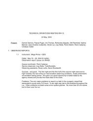
Figure 19: View <strong>of</strong> <strong>the</strong> UWAL 36” wind<br />
tunnel shownfrom <strong>the</strong> inlet end, looking<br />
toward <strong>the</strong> testsection and <strong>the</strong> power unit at<br />
<strong>the</strong> rear.<br />
11.2 UWAL 36” Wind Tunnel<br />
The UWAL 36” wind tunnel is housed in an<br />
independent building adjoining <strong>the</strong> Kirsten wind tunnel<br />
facility. This single story building is completely<br />
devoted to <strong>the</strong> wind tunnel, so <strong>the</strong>re is no intrusion with<br />
any o<strong>the</strong>r laboratories or <strong>of</strong>fice space. The wind tunnel<br />
uses an open circuit, straight through design, with an<br />
inlet filter and baffle section, tapering down to <strong>the</strong> test<br />
section, <strong>the</strong>n diverging to <strong>the</strong> single propeller power unit at <strong>the</strong> exhaust end.<br />
The test section has a rectangular, 36”x36” cross section, and is 8’ long. Both sides and <strong>the</strong> top are<br />
made <strong>of</strong> plexiglass, with steel streng<strong>the</strong>ning members which <strong>of</strong>fers clear visibility <strong>of</strong> <strong>the</strong> model being<br />
tested for a wide range <strong>of</strong> viewing angles. Since <strong>the</strong> wind tunnel is located in <strong>the</strong> middle <strong>of</strong> <strong>the</strong><br />
building, <strong>the</strong>re is adequate room ( > 10’) between <strong>the</strong> building walls and <strong>the</strong> test section for convenient<br />
placement <strong>of</strong> cameras, lights and video equipment. This wind tunnel does not have any lighting<br />
equipment, so all <strong>the</strong> necessary lights with tripods will have to be provided by us.<br />
The floor <strong>of</strong> <strong>the</strong> test section has a rectangular opening, ~2’6”x2’, closed by a wooden trap door on<br />
which <strong>the</strong> model is mounted (see Figure 21). The trap door is bolted from underneath, making access<br />
easy. In addition, one <strong>of</strong> <strong>the</strong> side walls <strong>of</strong> <strong>the</strong> test section is a hinged window running almost <strong>the</strong> entire<br />
length <strong>of</strong> <strong>the</strong> test section, which thus provides free access to <strong>the</strong> model between tests (and is <strong>of</strong> course<br />
kept closed during testing).<br />
The power unit is a variable pitch propeller driven by an electric drive (Figure 20, right). The wind<br />
speed is controlled manually by adjusting <strong>the</strong> pitch <strong>of</strong> <strong>the</strong> blades through a hydraulic control<br />
mechanism. The free stream wind speed in <strong>the</strong> test section is measured using a U-tube manometer<br />
(Figure 20, left) one end <strong>of</strong> which is connected to a fixed point on <strong>the</strong> upwind side and <strong>the</strong> o<strong>the</strong>r to <strong>the</strong><br />
test section. The differential reading on manometer has been directly calibrated to wind speed. The<br />
maximum wind speed at which <strong>the</strong> unit may be run continuously is 140 mph.
![Documentation [PDF] - Canada France Hawaii Telescope ...](https://img.yumpu.com/26965302/1/190x245/documentation-pdf-canada-france-hawaii-telescope-.jpg?quality=85)