Create successful ePaper yourself
Turn your PDF publications into a flip-book with our unique Google optimized e-Paper software.
iolase.com<br />
NASDAQ: BLTI<br />
USA<br />
BIOLASE ® Technology, Inc.<br />
4 Cromwell<br />
Irvine, CA 92618<br />
949.361.1200<br />
Europe<br />
EC REP<br />
MT Promedt Consulting GmbH<br />
Altenhofstrasse 80<br />
D-66386 St. Ingbert<br />
Germany<br />
+49 6894 581020<br />
www.mt-procons.com<br />
© 2008, <strong>Biolase</strong>® 5100109 REV. D (12/10)
USER MANUAL
USER MANUAL<br />
© 2008 BIOLASE Technology, Incorporated. All Rights Reserved.<br />
BIOLASE <strong>Waterlase</strong> ® <strong>C100</strong> YSGG User Manual.<br />
BIOLASE, the BIOLASE logo, <strong>Waterlase</strong>, and the <strong>Waterlase</strong> ® <strong>C100</strong> logo<br />
are either registered trademarks or trademarks of BIOLASE Technology<br />
Incorporated in the United States and/or other countries.<br />
biolase.com<br />
NASDAQ: BLTI<br />
USA<br />
BIOLASE ® Technology, Inc.<br />
4 Cromwell<br />
Irvine, CA 92618<br />
949.361.1200<br />
Europe<br />
EC REP MT Promedt Consulting GmbH<br />
Altenhofstrasse 80<br />
D-66386 St. Ingbert<br />
Germany<br />
+49 6894 581020<br />
www.mt-procons.com<br />
5100109 REV. D (12/10)
CONTENTS<br />
INTRODUCTION ..............................................7<br />
Section 1 INSTALLATION OF THE WATERLASE <strong>C100</strong> .........................7<br />
Installation Instructions ..........................................7<br />
Facility Requirements ...........................................7<br />
Electrical Supply ............................................7<br />
Compressed Air Supply/Laser Internal Co .........................7<br />
Section 2 SAFETY WITH THE WATERLASE <strong>C100</strong>. . . . . . . . . . . . . . . . . . . . . . . . . . . . .9<br />
Precautions ..................................................9<br />
Safety Instructions .............................................9<br />
Safety Features ...............................................10<br />
Energy Monitor ............................................10<br />
Circuit Breaker ............................................10<br />
Keyswitch ................................................10<br />
READY Button ............................................11<br />
Footswitch ...............................................11<br />
Remote Interlock Outlet .....................................11<br />
Emergency Stop (Figure 8) ...................................11<br />
Functional Panel ..........................................11<br />
Layout of Control Elements ...................................11<br />
Section 3 EQUIPMENT ................................................12<br />
General ....................................................12<br />
Optical Power Unit Elements .....................................12<br />
Control Panel .............................................12<br />
Keyswitch (Figures 2 & 7) ....................................12<br />
Footswitch Connector (Figure 7) ...............................14<br />
Remote Interlock (Figure 7) ..................................14<br />
Power Connection (Figure 7) .................................14<br />
Circuit Breaker (Figure 7) ....................................14<br />
Ventilation Channels (Figure 7) ................................14<br />
Locking Wheels (Figure 6) ...................................14<br />
Front Handle (Figure 6) .....................................14<br />
Back Panel (Figure 7) .......................................14<br />
Handpiece Holder (Figure 8) .................................14<br />
Air Input (Figure 7) .........................................14<br />
Self Contained Water System (Figure 7) .........................14<br />
©2008 BIOLASE Technology Inc. All Rights Reserved.
5100109 REV. D (12/10)<br />
Delivery System Support Arm with Hook (Figure 6) .................14<br />
Water Bottle Switch (Figure 7) .................................14<br />
Fill/Drain Connector (Figure7) .................................14<br />
<strong>Waterlase</strong> MD Delivery System ...................................18<br />
Handpiece ...............................................18<br />
Laser Tip ................................................18<br />
Trunk Fiber ...............................................18<br />
Delivery System Connections on the Unit ........................18<br />
Handpiece Collar ...........................................18<br />
Quick Release Mechanism/Tabs ...............................18<br />
Optical Shaft ..............................................18<br />
Tip Plug (for tip) ...........................................18<br />
Protective Rubber Cap (for fiber optic connector) ..................18<br />
Laser Connector Housing ....................................18<br />
Handpiece Holder .........................................19<br />
Protective Cover ...........................................19<br />
Rear Plug ................................................19<br />
Tip Remover ..............................................19<br />
Revolving Tip Holder ........................................19<br />
Section 4 OPERATING INSTRUCTIONS .................................. 20<br />
Setup ................................................... 20<br />
Connect Unit to Operatory .................................. 20<br />
Fill Self Contained Water System Bottle ......................... 20<br />
Secure Fiber Optic Assembly to Unit .............................. 21<br />
Connecting Handpiece to Fiber Optic Cable. ..................... 22<br />
Disconnecting the Handpiece ................................ 22<br />
Installing Tip in the Handpiece ............................... 23<br />
Changing Tips ............................................ 24<br />
Operation .................................................. 24<br />
Overview ............................................... 24<br />
Tip Cleaning and Inspection ................................. 25<br />
Operational State Description ................................ 25<br />
To Start the <strong>Waterlase</strong> ® <strong>C100</strong> ................................ 25<br />
Modify and Save Preferred Values as Presets .................... 27<br />
Activate the <strong>Waterlase</strong> ® <strong>C100</strong> ................................ 27<br />
Turn the <strong>Waterlase</strong> ® <strong>C100</strong> Off ................................ 27<br />
Error Messages ........................................... 27<br />
Section 5 WATERLASE ® <strong>C100</strong> SPECIFICATIONS ........................... 28<br />
General ................................................... 28<br />
Dimensions (W x L x H) .................................... 28<br />
Electrical ............................................... 28
<strong>Waterlase</strong> ® <strong>C100</strong> ......................................... 28<br />
Optical ................................................ 28<br />
Section 6 CONTRAINDICATIONS, WARNINGS AND PRECAUTIONS ............ 29<br />
Contraindications ............................................ 29<br />
Indications, Warnings and Precautions ............................ 29<br />
Eyewear ................................................ 29<br />
Anesthesia .............................................. 29<br />
Treatment, Technique and Settings ............................ 29<br />
Curettage Procedures ...................................... 29<br />
Fluid Entrapment and Air Embolism ........................... 29<br />
Root Canal Procedures ..................................... 30<br />
Adjacent Structures ....................................... 30<br />
Clinical Conditions ........................................ 30<br />
Tissue Evaluation ......................................... 31<br />
Tissue Contact and Tip Breakage ............................. 31<br />
Tip Changing ............................................ 31<br />
Water Splashing .......................................... 31<br />
Plume Removal .......................................... 31<br />
Dental Materials .......................................... 31<br />
Training ................................................ 31<br />
Section 7 CLINICAL APPLICATIONS ..................................... 32<br />
Introduction ................................................ 32<br />
Hard Tissue Cutting ....................................... 32<br />
Soft Tissue Incision, Excision and Ablation ...................... 33<br />
Procedure Guidelines ...................................... 33<br />
Presets for Soft and Hard Tissue Procedures ..................... 33<br />
Fiber Tip Calibration Chart .................................. 37<br />
Tip Specifications ......................................... 37<br />
Handpiece Cleaning and Sterilization ......................... 37<br />
Handpiece Cleaning ....................................... 37<br />
Steam Sterilization for Handpiece and Tips ...................... 38<br />
<strong>Waterlase</strong> ® <strong>C100</strong> Indications for Use .............................. 39<br />
Hard Tissue ............................................. 39<br />
Soft Tissue .............................................. 40<br />
Section 8 MAINTENANCE ............................................. 41<br />
Annual Maintenance ......................................... 41<br />
Delivery Maintenance ......................................... 41<br />
Daily Maintenance ........................................... 41<br />
Transportation .............................................. 41<br />
Storage ................................................... 41<br />
©2008 BIOLASE Technology Inc. All Rights Reserved.
6<br />
Section 9 CALIBRATION .............................................. 42<br />
Calibrating Power ............................................ 42<br />
Calibration Schedule .......................................... 43<br />
Appendix A: INSTRUCTIONS FOR FILLING THE INTERNAL COOLING RESERVOIR .... 44<br />
Appendix B: LABELS .................................................. 49<br />
5100109 REV. D (12/10)<br />
Laser Hazard Symbol ......................................... 49<br />
High Voltage Hazard Symbol .................................... 49<br />
Certification ................................................ 49<br />
Non-Interlocked Protection Housing Warning ....................... 49<br />
Laser Aperture .............................................. 49<br />
Attention Label .............................................. 50<br />
Protective Ground ............................................ 50<br />
Laser Explanatory Label ....................................... 50<br />
Ground ................................................... 50<br />
Indentification .............................................. 50<br />
Electrical Ratings ............................................ 51<br />
Cooling System Fill/Drain ...................................... 51<br />
Air Label ................................................... 51<br />
Key Switch ................................................. 51<br />
Water Spray ON/OFF ......................................... 51<br />
Remote Label ............................................... 51<br />
ETL Listed ................................................. 51<br />
Footswitch Label ............................................. 51<br />
Emergency Stop Label ........................................ 51<br />
Appendix C: SPARE PARTS AND ACCESSORIES ............................. 54<br />
Appendix D: CLINICAL PROCEDURE GUIDELINES ........................... 55<br />
Root Canal Clinical Protocol .................................... 55<br />
Procedure .............................................. 55<br />
Apicoectomy Clinical Protocol ................................... 57<br />
Procedure .............................................. 57<br />
Appendix E: WATERLASE ® <strong>C100</strong> WARRANTY ................................ 60
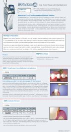
INTRODUCTION<br />
The <strong>Waterlase</strong> ® <strong>C100</strong> Er,Cr:YSGG (Erbium, Chromium: Yttrium, Scandium, Gallium, Garnet) tissue cutting system is a unique device<br />
with diverse hard and soft tissue dental applications. For hard tissue procedures, the <strong>Waterlase</strong> ® <strong>C100</strong> utilizes advanced laser<br />
and water atomization technologies to safely and effectively perform tissue cutting, shaving, contouring, roughening, etching and<br />
resection. For soft tissue procedures, the <strong>Waterlase</strong> ® <strong>C100</strong> utilizes direct laser energy to perform tissue removal, incision, excision,<br />
ablation and coagulation.<br />
For hard tissue procedures, the YSGG solid-state laser provides optical energy to a user controlled distribution of atomized water<br />
droplets. As the water droplets absorb the optical energy, hydrokinetic cutting effects results. The hydrokinetic process refers to the<br />
removal of tissues with highly energized water particles. Strong absorption of laser energy by atomized water droplets results in an<br />
intense yet controlled water particle excitation and micro-expansion. The resulting forces induce mechanical separation of surface<br />
material, yielding quick and clean mechanical hard tissue removal. A flexible fiber optic cable with a handpiece delivers the unique<br />
laser wavelength and atomized distribution of water particles to the tissue target. A red light emitted from the handpiece distal end<br />
pinpoints the area of treatment. The optical power output and atomized water spray may be adjusted to specific user requirements<br />
for both soft and hard tissue applications.<br />
For soft tissue applications a different mode of operation is utilized. In soft tissue mode, the <strong>Waterlase</strong> ® <strong>C100</strong> is programmed to<br />
perform tissue removal, incision, excision, ablation and coagulation using direct laser energy either with or without water for cooling<br />
and hydration.<br />
Use of this device requires proper clinical and technical training. This manual provides instructions for use for trained professionals.<br />
When used and maintained properly, the <strong>Waterlase</strong> ® <strong>C100</strong> will prove a valuable addition to your practice. Please contact your<br />
authorized local BIOLASE representative if you have any questions or require assistance.<br />
CANADA: This device must be installed and operated according to the guidelines of CAN/CSA-Z3 86-92, “Laser<br />
Safety in a Health Care Facility”.<br />
SECTION 1: INSTALLATION OF THE WATERLASE ® <strong>C100</strong><br />
INSTALLATION INSTRUCTIONS<br />
Upon request, your local authorized BIOLASE representative will unpack the <strong>Waterlase</strong> ® <strong>C100</strong> and your service representative will<br />
install the unit.<br />
FACILITY REQUIREMENTS<br />
Electrical Supply<br />
USA (UL) 115 VAC @ 16.0 A<br />
International: 230 VAC @ 8.0 A<br />
Compressed Air Supply<br />
• 80 - 120 psi (5.5 - 8.2 bar)<br />
©2008 BIOLASE Technology Inc. All Rights Reserved.<br />
7
• Moisture in the air supply line may damage the laser system. Please provide proper filtration to eliminate all moisture from air<br />
source.<br />
Connections for air supply must be available in each operatory.<br />
Attach air hose with 1/4” inside diameter male quick connectors on each end between air inlet connector (Figure 7) and operatory<br />
air source.<br />
To fill cooling system, please refer to the instruction sheets P/N 5000875 that are included in the package containing the funnel<br />
assembly.<br />
For reference, the Instructions For: Filling the Internal Cooling Reservoir P/N 5000875 are included in this manual, see Appendix A.<br />
8<br />
CAUTION: Prior to connection, verify that outlet is for air, not water supply. Connection to water supply may cause damage to<br />
the <strong>Waterlase</strong> ® <strong>C100</strong> system. If the unit was connected to the water supply, do NOT turn the system on. Contact<br />
your service representative.<br />
CAUTION: Unit must not be operated without filling the internal cooling system reservoir with DI or Distilled water. Improper<br />
filling may damage the unit. Please read the instructions carefully.<br />
5100109 REV. D (12/10)
SECTION 2: SAFETY WITH THE WATERLASE ® <strong>C100</strong><br />
PRECAUTIONS<br />
Failure to comply with precautions and warnings described herein may lead to exposure to dangerous voltage levels or optical<br />
radiation sources. Please comply with all safety instructions and warnings.<br />
CAUTION: Use of controls or adjustments or performance of procedures other than those specified herein may result in<br />
SAFETY INSTRUCTIONS<br />
Follow these safety instructions before and during treatments:<br />
1. Remove or cover all highly reflective items in the treatment area, if possible.<br />
2. Do not operate in the presence of explosive or flammable materials.<br />
3. All persons present in the operatory must wear protective eyewear suitable for blocking 2.78 µm wavelength spectrums. Ensure<br />
<strong>Waterlase</strong> ® <strong>C100</strong> Handpiece Mirror is clean and there is no evidence of moisture or water present (refer to mirror inspection<br />
and remove inspection kit).<br />
hazardous radiation exposure.<br />
CAUTION: This unit has been designed and tested to meet or exceed the requirements of severe electromagnetic,<br />
electrostatic and radio frequency interference testing. However, the possibility of electromagnetic or other<br />
interference may still exist.<br />
CAUTION: DO NOT USE THIS UNIT IN ANY MANNER OTHER WHICH IS NOT DESCRIBED HEREIN. DO NOT USE THE UNIT<br />
IF YOU SUSPECT IT IS FUNCTIONING IMPROPERLY.<br />
CAUTION: Periodically inspect eyewear for pitting and cracking.<br />
NOTE: For replacement, additional, or prescription protective eyewear, please contact your <strong>Waterlase</strong> ® <strong>C100</strong><br />
representative.<br />
4. Do not look directly into the beam or at specular reflections.<br />
5. Direct the cutting spray toward targeted tissues only.<br />
6. Press STANDBY (Standby button) on the control panel before turning off the unit.<br />
7. Press STANDBY on the control panel before exchanging handpieces or removing the fiber optic connector from the unit.<br />
8. Move the circuit breaker to OFF (O) position (located on rear panel) and remove the key before leaving unit unattended.<br />
DANGER: DO NOT remove system housing. Danger from radiation exposure and high voltage may exist.<br />
©2008 BIOLASE Technology Inc. All Rights Reserved.<br />
9
All operatory entrances must be marked with an approved laser warning sign.<br />
SAFETY FEATURES<br />
10<br />
Energy Monitor<br />
The energy monitor measures and verifies power output. Power deviations of more than 20% from the selected value will cause<br />
the display to show an error message. The unit will not operate until the system is reset by pressing any key on the keypad. If<br />
error messages persist please contact your BIOLASE representative.<br />
Circuit Breaker<br />
The circuit breaker serves as a line switch to separate the unit<br />
from the main power supply (0 = OFF, 1 = ON).<br />
Keyswitch<br />
To switch unit ON, turn the key to the horizontal position.<br />
Use the proper key only. The key cannot be removed while<br />
in the ON position. Always remove key when not in use.<br />
5100109 REV. D (12/10)<br />
Figure 1: Circuit Breaker<br />
Figure 2: Keyswitch
READY Button<br />
Once the circuit breaker and key switch are set to the ON position, the READY button on the keypad must be pressed to enable the<br />
footswitch. Three beeps will sound to indicate that the system is ready for use.<br />
Footswitch<br />
The <strong>Waterlase</strong> ® <strong>C100</strong> will not activate until the user presses down on the footswitch. A<br />
protective cover prevents unintentional pressing of the footswitch.<br />
Remote Interlock Plug<br />
Each laser has a remote plug and connector on its rear panel. The purpose is to enable a user<br />
provided remote switch (e.g., on the entrance door) to turn OFF the laser. To use it properly<br />
requires a normally closed pair of contacts connected to pins 1 and 5 of the connector. These<br />
contacts should have no voltage associated with them and should open on activation.<br />
Emergency Stop (Figure 8)<br />
Push to activate emergency stop. Rotate and release button to restart. Do not use as a<br />
normal means to stop the laser.<br />
Functional Display<br />
The Liquid Crystal Display (LCD) and the Light Emitting Diode (LED) indicators on the control<br />
panel show the functional conditions of the system.<br />
Layout of Control Elements<br />
All control functions are located at a safe distance from energy output. Control panel layout is described in Section 3, Control Panel.<br />
NOTE: Please direct any safety questions to your local BIOLASE representative.<br />
Figure 3: Footswitch<br />
Figure 4: Emergency Stop<br />
©2008 BIOLASE Technology Inc. All Rights Reserved.<br />
11
SECTION 3: EQUIPMENT<br />
GENERAL<br />
The <strong>Waterlase</strong> ® <strong>C100</strong> dental laser system consists of two modules:<br />
• Optical Power Unit (the Unit)<br />
• <strong>Waterlase</strong> ® <strong>C100</strong> Atomizing Delivery System (the Delivery System)<br />
OPTICAL POWER UNIT ELEMENTS<br />
12<br />
Control Panel<br />
The control panel consists of three components (see Figure 5):<br />
• Buttons<br />
• Liquid Crystal Display (LCD)<br />
• Light Emitting Diodes (LEDs)<br />
Buttons<br />
The buttons allow for selection and control of all system variables.<br />
• ON/OFF Turns System ON and OFF.<br />
• STANDBY Disables the unit.<br />
• READY Enables the unit.<br />
• + / - Adjusts AIR, WATER, POWER and FREQUENCY values.<br />
• MODE Selects air and water operational states (ON, OFF, AUTO).<br />
• PRESETS System is programmed with 4 PRESETS, or values can be 1, 2, 3, 4 customized<br />
5100109 REV. D (12/10)<br />
(Section 4: Modify and Save Preferred Values and Presets).<br />
• f FUNCTION Selects frequency or power mode, and service.<br />
LCD (Liquid Crystal Display)<br />
The LCD display shows settings, error messages and system status.<br />
LEDs (Light Emitting Diodes)<br />
The LED lights indicate selection of the corresponding function (setting).<br />
Keyswitch (Figures 2 & 7)<br />
The key can be removed only when in OFF position.
Power Display LCD 14<br />
Power Display LCD 13<br />
Buttons<br />
On/Off Button 1<br />
Water Display LCD 12<br />
Water Up/Down 11<br />
Buttons<br />
Figure 5: Control Panel<br />
2 Standby Button<br />
3 Ready Button<br />
4 Function Button<br />
5 Preset LEDs (4)<br />
6 Preset Buttons (4)<br />
7 Air Display LCD<br />
8 Air Mode Button<br />
9 Air Up/Down<br />
Buttons<br />
10 Water Mode<br />
©2008 BIOLASE Technology Inc. All Rights Reserved.<br />
13
14<br />
Footswitch Connector (Figures 7)<br />
Connect and secure footswitch (Figure 3).<br />
Remote Interlock (Figures 7)<br />
Plug in the remote interlock connector.<br />
Power Connection (Figures 7)<br />
Attach power cord to unit at this location.<br />
Circuit Breaker (Figures 7)<br />
Serves as a line switch to separate the unit from the main power supply.<br />
Ventilation Channels (Figures 7)<br />
Do not cover or block these channels. They provide airflow path to cool unit.<br />
Locking Wheels (Figures 6)<br />
Press down on front tabs to render unit unmovable. Lift up the tabs to release locking mechanism.<br />
Front Handle (Figures 7)<br />
Do not use to lift the unit.<br />
Back Panel (Figures 7)<br />
Handpiece Holder (Figures 8)<br />
Holds handpiece when not in use.<br />
Air Input (Figures 7)<br />
Connect with tubing (included) to compressed dry air outlet. (80-120 PSI or 5.5-8.2 bar).<br />
Self Contained Water System (Figures 7)<br />
Provides water supply for handpiece atomization spray. Fill bottle only with deionized/distilled water. Do not use tap water.<br />
Delivery System Support Arm with Hook (Figures 6)<br />
Provides support for fiber optic cable to reduce stress at connection to the unit.<br />
Water Bottle Switch (Figures 7)<br />
To pressurize the water bottle that supplies water to the atomization spray.<br />
Fill/Drain Connector (Figures 7)<br />
Used to fill/drain the water-cooling system.<br />
5100109 REV. D (12/10)
Fiber Exit<br />
Emergency Stop Switch<br />
Handle<br />
Locking Wheels<br />
Figure 6: Front View<br />
Delivery System<br />
Support Arm<br />
with Hook<br />
Control Panel<br />
©2008 BIOLASE Technology Inc. All Rights Reserved.<br />
15
16<br />
Water Bottle Switch<br />
Patient Water Bottle<br />
Deionized/Distilled Water Only<br />
(Do not use tap water)<br />
Footswitch/Power Supply Rack<br />
Circuit Breaker<br />
Power Connection<br />
Air Input<br />
Fill/Drain Connector<br />
5100109 REV. D (12/10)<br />
Figure 7: Rear View<br />
Key Switch<br />
On/Off<br />
Back Panel<br />
Remote Interlock Outlet<br />
Ventilation<br />
Channels<br />
Footswitch Connector<br />
Ground Pin
Figure 8: Top View<br />
Control Panel<br />
Handpiece Holder<br />
Handpiece<br />
Emergency Stop Switch<br />
©2008 BIOLASE Technology Inc. All Rights Reserved.<br />
17
WATERLASE ® <strong>C100</strong> DELIVERY SYSTEM<br />
18<br />
Handpiece<br />
The handpiece rotates and is detachable from the optical shaft. It delivers optical energy and atomized cooling spray to the<br />
treatment area.<br />
Laser Tip<br />
The tip is detachable from the handpiece and serves as the optical power conduit to the tissue target.<br />
Trunk Fiber<br />
The fiber optic cable contains the optical fiber together with the air and water tubing. Laser radiation is delivered from laser unit<br />
to the handpiece through the optical fiber.<br />
Delivery System Connections on the Unit<br />
Please refer to Delivery System User Manual for specific connections instructions.<br />
Handpiece Collar<br />
The handpiece collar secures the handpiece to the fiberoptic cable.<br />
Quick Release Mechanism/Tabs<br />
To disconnect the handpiece or protective cover, squeeze on the two opposite dots with one hand, and with the other, twist the<br />
handpiece or protective cover off the shaft.<br />
Optical Shaft<br />
The optical shaft contains the fiberoptic cable and tip coupling mechanism.<br />
Tip Plug (for tip)<br />
The tip plug protects the handpiece optical components from damage due to water, contaminants or debris that could enter<br />
through the handpiece fiber tip orifice when tip is not in use.<br />
Protective Rubber Cap (for fiber optic connector)<br />
The protective rubber cap protects the input end of the fiber optic cable when not attached to unit.<br />
Laser Connector Housing<br />
The laser connector housing secures the delivery system to the unit.<br />
5100109 REV. D (12/10)
Handpiece Holder<br />
The handpiece holder supports the handpiece when not in use.<br />
Protective Cover<br />
The protective cover protects the optical shaft when handpiece is disconnected.<br />
Rear Plug<br />
The rear plug protects the handpiece when disconnected from optical shaft.<br />
Tip Remover<br />
The tip remover tool helps to remove and insert laser tips.<br />
Revolving Tip Holder<br />
The revolving tip holder holds up to 6 tips and functions as a tip remover (follow instructions enclosed with tip holder).<br />
©2008 BIOLASE Technology Inc. All Rights Reserved.<br />
19
SECTION 4: OPERATING INSTRUCTIONS<br />
SETUP<br />
20<br />
Connect Unit to Operatory<br />
1. Verify circuit breaker is in OFF position.<br />
2. Verify keyswitch is in OFF position.<br />
3. Connect power cord to unit (see Figure 7).<br />
4. Verify minimum air pressure of 80 psi (5.2 bar) and maximum of 120 psi<br />
(8.2 bar) from clean air supply.<br />
5. Check air supply for moisture.<br />
WARNING: Do not connect the operatory air supply to the unit if<br />
6. Connect to the unit air supply (see Figure 7).<br />
Fill Self Contained Water System Bottle<br />
7. Push switch on bottle mounting bracket to OFF position.<br />
NOTE: If bottle was pressurized, you will hear a hissing sound<br />
8. After bottle is depressurized unscrew from mounting bracket. Fill bottle<br />
with distilled or sterile water only.<br />
9. Attach bottle back to mounting bracket.<br />
5100109 REV. D (12/10)<br />
water or oil is present. Air compressor may need to be<br />
drained or cleaned and air filters installed if moisture<br />
appears. Wet air will damage the unit. Check air supply<br />
weekly to verify absence of water and oil.<br />
while bottle depressurizes.<br />
CAUTION: Do not use tap water.<br />
NOTE: Remove the Handpiece Package and the Tip Package<br />
and set aside on flat surface. Remove the Delivery<br />
System and place on a flat surface.<br />
CAUTION: Do not excessively or forcibly bend the Delivery System. The<br />
minimum bending diameter is 6”-7”.<br />
Figure 10: Rear Plug Release<br />
Figure 11: Protective Cap Release<br />
Figure 12: Handpiece Connection
Figure 13: Unplugging the Handpiece<br />
Secure Fiber Optic Assembly to Unit<br />
Remove the protective cap (red or black) from the Fiber Optic Connector<br />
and <strong>Waterlase</strong> ® <strong>C100</strong> Laser Aperture.<br />
CAUTION: DO NOT POWER UP YOUR LASER UNTIL THE HAND-<br />
• Place the Delivery Support Arm into the mounting hole on the Delivery<br />
System Mounting Plate.<br />
• For SMA insertion: align the blue dot of the SMA Housing with the blue<br />
dot on the mounting plate Center shaft. Slide the Fiber Optic Connector<br />
and alignment pin into the alignment pin hole.<br />
• Once the connector reaches the Laser Aperture, turn the Locking Nut<br />
Clockwise.<br />
PIECE AND TIP ARE PROPERLY INSTALLED. FAILURE<br />
TO DO SO MAY DAMAGE THE SYSTEM.<br />
©2008 BIOLASE Technology Inc. All Rights Reserved.<br />
21
22<br />
CAUTION: When first turning the Locking Nut onto the Laser Aperture, if it seems tight, turn counter clockwise until<br />
• Tighten the Locking Nut by turning it clockwise until fully seated.<br />
• Place the Delivery Support Arm into the mounting hole on the Delivery System Mounting Plate.<br />
• Snap the Delivery System into the hook on the end of the Delivery System Support Arm (figure 6) and place the<br />
Fiber Optic Shaft into the Handpiece Holder (figure 8).<br />
Connecting Handpiece to Fiber Optic Cable<br />
1. Remove Handpiece and Tip Remover from package. Hold the Handpiece and squeeze on the two opposite release<br />
tabs to release the Rear Plug, then twist the rear plug out. (Figure 10).<br />
2. CAREFULLY remove protective cap by squeezing on the two opposite tabs and twist cover off the Delivery System (Figure 11).<br />
3. Prior to assembling the handpiece, check for water contamination. Verify that NO water is present along the fiberoptic<br />
shaft, and on fiber ferrule. For cleaning and drying, use lint free tissue.<br />
4. Connect handpiece. The handpiece should be pointed straight up when the handpiece is connected or disconnected<br />
(see Figure 12). Taking care not to scrape the handpiece against the fiber ferrule (Figure 12 (c)), slide the handpiece<br />
down the shaft until it clicks into place at the quick release tabs. The handpiece MUST be properly secured to the<br />
fiberoptic shaft (Figure 12 (b)). The protective cap is NOT a substitute for a handpiece.<br />
Disconnecting the Handpiece<br />
1. Turn the water bottle Toggle Switch to “OFF” position.<br />
2. While laser is in the “Ready” mode, with Tip attached, dry out the water line:<br />
a) switch laser to ENAMEL mode (pre-set 1);<br />
b) turn Air and Water to “ON” mode;<br />
c) wait for 15 seconds (and watch clear tubing) to dry water out;<br />
d) switch Air and Water back into AUTO mode.<br />
5100109 REV. D (12/10)<br />
loose and try again.<br />
NOTE: Refer to the <strong>Waterlase</strong> ® <strong>C100</strong> Interactive CD supplied by BIOLASE.<br />
CAUTION: Do not bump protective cover into fiber ferrule.<br />
CAUTION: The Handpiece should always be connected when turning “ON” the laser.<br />
CAUTION: Make sure that the water bottle toggle switch is in “OFF” position when turning ON the laser.<br />
WARNING: Disconnecting the Handpiece without drying out the water line may cause severe damage to the Hand-<br />
piece and Trunk Fiber!
3. While laser is in the “Ready” mode, carefully disconnect Fiber Tip using Revolving Tip Holder or Tip Remover and<br />
replace it with Tip Plug. Press “Standby” button.<br />
4. Disconnect the Handpiece. Place the Protective Cap on the Fiber Optic Shaft.<br />
5. Connect the Rear Plug to the Handpiece. Turn System OFF.<br />
NOTE: Before autoclaving, if Handpiece has not been dried out, always blow compressed air through the inside<br />
Installing Tip Into Handpiece<br />
body and only then plug both ends of the Handpiece. See sterilization instructions and draft.<br />
CAUTION: Always use the Tip Remover (Figure18 [a ])or Revolving Tip Holder during tip installation and changing<br />
tip. DO NOT use your fingers. To prevent contamination and damage to Handpiece, Tip Plug [Figure 18<br />
(e)] must be in place at all times when no tip is installed and the laser is not in use.<br />
Figure 16: Tip Installation Figure 17: Correct Tip Connection<br />
Place the system on READY when removing/replacing a tip. Blowing air prevents moisture or dirt from entering the handpiece.<br />
NOTE: Always use the Tip Remover to replace or remove tips from the Handpiece.<br />
Remove the tip from the package and slide into the Tip Remover or Tip Holder over the first groove on the Tip Ferrule<br />
(Figure 16 (b)). This allows easy insertion and removal of the tip into and from the Tip Orifice (Figure 17).<br />
Insert the tip, keeping it perpendicular to the handpiece. The tip is fully seated when the tip remover arrives at a point<br />
flush against the tip orifice (Figure 17).<br />
Slide the handpiece laterally off the tip remover or tip holder. Now the tip is installed and the handpiece is ready for use.<br />
CAUTION: Do not operate the laser, or air/water spray without the tip inserted into the handpiece.<br />
©2008 BIOLASE Technology Inc. All Rights Reserved.<br />
23
Changing Tips<br />
Slide Tip Remover laterally on the tip groove and CAREFULLY pull the tip straight out (Figure 18). The same motion is used<br />
with Tip Remover.<br />
Remove tip from Tip Remover and slide in the new tip. Insert the new tip by following the instructions presented in Section 4:<br />
Disconnecting the Handpiece<br />
OPERATION<br />
CAUTION: The laser unit must be in “READY” mode when removing/replacing tips. Always wear laser protective<br />
Overview<br />
<strong>Waterlase</strong> ® <strong>C100</strong> provides user control for Power, Water and Air parameters. The user may select a Preset (a set of stored values<br />
and modes of operation for Power, Water and Air), or vary the individual values to adjust Power, Water and Air as appropriate for<br />
the procedure. The following table shows the range of values for Power, Water and Air and their operational states.<br />
5100109 REV. D (12/10)<br />
glasses when replacing the tips and laser is in READY mode. Ensure that no water is present on the tip<br />
or around tip orifice during tip replacement.<br />
CAUTION: DO NOT pull tip with Tip Remover tilted.<br />
WARNING: Use of controls or adjustments and performance of procedures other than those specified herein may result in<br />
hazardous radiation exposure.<br />
Figure 17: Changing TIps<br />
Table 1: Range of Values and Operational States and Modes for the Power and Air & Water Spray<br />
24<br />
Parameter Range of Values<br />
Operational<br />
State<br />
“ON” Mode<br />
“Auto” Mode<br />
Water and Air<br />
F/S Off F/S On<br />
“OFF” Mode<br />
Power 0.0–6.0 Watts Standby N/A - - N/A<br />
Ready N/A - + N/A<br />
Water 0–100% Standby - - - -<br />
Ready + - + -<br />
Air Standby - - - -<br />
Ready + - + -
Table 1a: Range of Power Versus Frequency<br />
Power Setting 10 Hz 15 Hz 20 Hz 25 Hz 30 Hz<br />
0.1 √ √ √ √ √<br />
0.025 √ √ √ √ √<br />
1.0 √ √ √ √ √<br />
3.0 √ √ √ √ √<br />
4.5 √ √ √ √<br />
6.0 √ √ √<br />
Tip Cleaning and Inspection<br />
BEFORE AND AFTER EACH USE the tip surfaces must be inspected for chips, pits and cleanliness. (Refer to tip inspection and<br />
cleaning kit) DO NOT USE A TIP THAT HAS CHIPS, PITS OR IS NOT CLEAN. The cutting effectiveness will be lessened, and<br />
damage on the handpiece may occur, to minimize risks do the following:<br />
• New tips or tips in use must be cleaned wearing gloves or finger cots. Clean the tip surfaces with PURE ACETONE (OR 100%<br />
ALCOHOL ONLY IF ACETONE IS NOT AVAILABLE). Pay particular attention to the distal end of the tip as IT MAY REQUIRE<br />
SOME SCRUBBING (30 sec. to 1 minute) TO REMOVE ANY DEBRIS.<br />
• One of the easiest ways to clean the tips is to leave the tip in the tip remover and cover the open slot with your finger. This will<br />
hold the tip in place while you scrub with lint free “Q” tips or wipes.<br />
• After installation of the tip, WIPE THE END ONE MORE TIME TO ENSURE CLEANLINESS.<br />
Operational State Description<br />
Each function (Power, Water and Air) has a separate display, indicating the value of the parameter and its mode. For example,<br />
when the mode is in “AUTO” Water, and/or Air will flow, only when the footswitch is pressed and power is emitted. The mode and,<br />
or value of Air and Water function may be adjusted by keys below the associated display. The following are examples of the Water<br />
and Air displays showing a 70% value setting for Water, a 90% value setting for Air, and an AUTO mode setting for both.<br />
Water Display Air Display<br />
To Start the <strong>Waterlase</strong> ® <strong>C100</strong><br />
1. Verify that all connections have been properly secured.<br />
2. The Air supply must be connected and the external air pressure must provide at least 80 PSI to 120 PSI.<br />
3. Electrical input must be 115 VAC, maximum 16 amperes for U.S. (230VAC, 8 Ampere for International).<br />
4. The Handpiece must be properly connected.<br />
©2008 BIOLASE Technology Inc. All Rights Reserved.<br />
25
26<br />
5. Verify that the water bottle is clean and filled with at least 1/3 full with distilled or deionized water and that the pressure switch is<br />
in the “OFF” position.<br />
6. Power and Frequency share the same display. Toggle the “f” key to set mode of frequency or power selection; press the “Treat<br />
Beam” up/down buttons to increase/decrease frequency or power.<br />
7. The Emergency Stop button must be in a release position.<br />
8. Turn the circuit breaker to ON position.<br />
9. Insert the key into the switch and rotate clockwise to the ON position.<br />
10. Press the On/Off button on the front panel to start the unit.<br />
11. Self-Test messages will appear, after a 3 second delay.<br />
12. Attach handpiece to the fiber optic cable shaft (Section 4: Connecting Handpiece to Fiber Optic Cable).<br />
13. Press the Ready button and attach the tip using the tip remover tool (Section 4: Installing Tip Into Handpiece).<br />
14. Select the appropriate parameters for the procedure. The mode and value of each parameter may be adjusted by the keys<br />
below the associated display. To select a Preset, simply push the button next to the preset value (Figure 5).<br />
15. Turn water bottle switch to ‘ON’ position and proceed.<br />
5100109 REV. D (12/10)
Modify and Save Preferred Values as Presets<br />
Selecting pulse frequency<br />
Press “f” button to switch from power adjustment mode & pulse frequency adjustment. Press “up” or “down” buttons of<br />
treatment Beam to select frequency. Press “f” again to go back to power adjustment mode. Beware of power range limitations<br />
depending on frequency (table 1a).<br />
The <strong>Waterlase</strong> ® <strong>C100</strong> has four pre-programmed presets stored on the system. The values of the presets, as well as additional<br />
combinations of presets, are presented in Section 7: Fiber Tip Calibration Chart.<br />
To select and store a new set of values for Power, Frequency, Water and Air, first select the preset number (1, 2, 3 or 4) that<br />
you wish to change. Then, select the desired values and mode for Power, Water and Air. After all variables have been set, push<br />
the selected preset button and hold in place for 2-3 seconds until you hear a beep. The beeper demonstrates that the new<br />
values and modes are now stored. These new values and modes are permanently stored under that preset number and may be<br />
recalled at any time by pushing the preset button.<br />
Activate the <strong>Waterlase</strong> ® <strong>C100</strong><br />
Push the Ready button to enable the <strong>Waterlase</strong>® <strong>C100</strong>, and depress the footswitch when ready.<br />
NOTE: The user may evaluate the effect of each parameter setting prior to the procedure by directing the hand-<br />
Turn the <strong>Waterlase</strong> ® <strong>C100</strong> Off<br />
1. Turn the water bottle switch to OFF position.<br />
2. Set Air, Water to 100%, ON mode. Wait until hearing the water bubling sound.<br />
3. Remove the tip, then remove the handpiece.<br />
4. Press STANDBY button.<br />
5. Push the ON/OFF button.<br />
6. Turn key to OFF position.<br />
Error Messages<br />
piece into a paper cup or sink and adjusting the values as desired.<br />
The <strong>Waterlase</strong> ® <strong>C100</strong> constantly monitors its own performance and calibration. If any performance errors occur, the text at the<br />
top of the power display will indicate the cause of the error and when required for safety, the device will go to the Standby Mode.<br />
The error must be cleared to resume operation. The cleared error will be indicated when the top line of the text shows “BIOLASE<br />
TECHNOLOGY” in place of “SYSTEM ERROR.”<br />
©2008 BIOLASE Technology Inc. All Rights Reserved.<br />
27
SECTION 5: WATERLASE ® <strong>C100</strong> SPECIFICATIONS<br />
GENERAL<br />
28<br />
Dimensions<br />
• Unit 12.55 x 27.73 x 33.28 in (32 x70 x 84.5cm)<br />
• With Fiber 12.55 x 27.73 x 52.5 in (32 x 66 x 133.5 cm)<br />
• Weight 110 lbs (50 kg)<br />
Electrical<br />
• Operating Voltage: 115 VAC ± 10% (230 VAC ± 10% international)<br />
• Frequency: 50/60 Hz<br />
• Current rating: 16.0 A (8 A international)<br />
• External fuses: None<br />
• Main control: Circuit breaker<br />
• On / Off control: Key switch<br />
• Remote interruption: Remote interlock connector<br />
<strong>Waterlase</strong> ® <strong>C100</strong><br />
• Water type: Distilled or DI<br />
• External air source: 80 - 120 psi. (5.5 - 8.2 bar)<br />
• Interaction zone: 0.5 - 3.0 mm from handpiece tip<br />
Optical<br />
• Laser classification: IV<br />
• Medium: Er, Cr:YSGG<br />
• Wavelength: 2.78 µm (2780 nm)<br />
5100109 REV. D (12/10)<br />
Erbium, Chromium, Yttrium, Scandium, Gallium, Garnet<br />
• Frequency: 10 - 30Hz (5Hz incremental step)<br />
• Average power: 0.0 - 6.0 W<br />
• Power accuracy: ± 20%<br />
• Pulse energy: 0 -300 mJ<br />
• Pulse duration: 140 - 150 µs<br />
• Delivery head angles: 0° (Straight) and 90° (Standard)<br />
• Delivery tip diameter: 200 – 1200 µm<br />
• Divergence: 8°<br />
• Mode: Multimode<br />
• Aiming Beam: Red 655 nm laser (safety classification I)<br />
• Nominal Ocular Hazard Distance: (NOHD) 5cm
SECTION 6: CONTRAINDICATIONS, WARNINGS & PRECAUTIONS<br />
CONTRAINDICATIONS<br />
All clinical procedures performed with the <strong>Waterlase</strong> ® <strong>C100</strong> must be subjected to the same clinical judgment and care as with<br />
traditional techniques. Patient risk must always be considered and fully understood before clinical treatment. The clinician must<br />
completely understand the patient’s medical history prior to treatment. Exercise caution for general medical conditions, which might<br />
contraindicate a local procedure. Such conditions may include, but are not limited to, allergy to local or topical anesthetics, heart<br />
disease, lung disease, bleeding disorders, sleep apnea or an immune system deficiency. It is advised that medical clearance be<br />
obtained from the patient’s physician when any doubt exists regarding treatment.<br />
Indications, Warnings and Precautions<br />
Eyewear<br />
Doctor, patient, assistant, and all others inside the operatory must wear appropriate laser protection eyewear for the 2.78 µm<br />
wavelength (OD 4).<br />
Anesthesia<br />
Although in most cases anesthesia may not be required, patients should be closely monitored for signs of pain or discomfort.<br />
If such signs are present, adjust settings, apply anesthesia or cease treatment if required. All precautions must be followed if<br />
flammable anesthesia is used in conjunction with any laser surgical system.<br />
Treatment, Technique and Settings<br />
Only licensed professionals who have successfully completed training should use this device. Always start treatment at the lowest<br />
power setting for the specific tissue and increase as required. Closely observe clinical effects and use your judgment to determine<br />
the aspects of the treatment (technique, proper power, air and water settings, tip type and duration of operation) and make<br />
appropriate power, air and water adjustments to compensate for varying tissue composition, density and thickness.<br />
All hard tissue (i.e., enamel, dentin, cementum, and bone) procedures must be performed using air and water spray at appropriate<br />
settings. Failure to use the spray will result in tissue thermal damage.<br />
Curettage Procedures<br />
Exercise extreme caution when using this device in areas where critical structures (i.e. nerves and vessels) could be damaged,<br />
such as in the apical third of the 3rd molar socket. Do not proceed with using the laser if visibility is limited in these areas.<br />
Fluid Entrapment and Air Embolism<br />
Do not direct air or spray toward tissues that may trap air/fluid. For example, when performing surgical procedures, the clinician<br />
should be aware of adjacent soft tissue pockets, cavities, or channels that may collect or entrap air/fluid. Always use high-speed<br />
suction to remove any excess fluid and avoid directing the spray into deep pockets, cavities or channels such as the socket<br />
©2008 BIOLASE Technology Inc. All Rights Reserved.<br />
29
30<br />
resulting from the extraction of a molar. Also, for example, avoid working through soft tissues adjacent to the roots of molars,<br />
especially the third inferior molars, which communicate directly with the sublingual and submandibular spaces. Do not use the<br />
<strong>Waterlase</strong> ® <strong>C100</strong> if access is limited and requires operation with spray within narrow or enclosed spaces that could collect or<br />
entrap air. In general, the same care and precautions should be taken when using the <strong>Waterlase</strong> ® <strong>C100</strong> as are taken when using<br />
any air and water emitting cutting device, including the high-speed drill.<br />
Root Canal Procedures<br />
Review the clinical procedure and all labeling instructions provided with the endodontic tips and EndoLase root canal kit before<br />
proceeding with any treatment. Always use air and water spray at the recommended settings to enlarge and remove debris from<br />
inside the root canal. Do not exceed the power setting of P= 1.5 W for root canal enlargement with any of the endodontic tips (Z2,<br />
Z3 or Z4).<br />
The <strong>Waterlase</strong> ® <strong>C100</strong> is better suited for straight and slightly curved canals. Great care should be taken during instrumentation of<br />
curved canals as the endodontic fiber tip may break or perforate through the wall of the curved canal. If during insertion the fiber<br />
tip does not advance easily into the canal, do not force the tip inside. A possibility is to pull the fiber out and use an endodontic<br />
hand file or a broach to open the path. The <strong>Waterlase</strong> ® <strong>C100</strong> is an end-cutting device; so to avoid penetration of a canal wall or<br />
the apical foramen, do not force the tip and/or activate the laser while moving the tip inside a narrow or curved canal, or through<br />
the apex. Place the end of the tip ~2mm from the apex or away from being in contact with the wall of a curved canal. Activate the<br />
laser and spray only during the outward stroke when the fiber tip is pulled towards the coronal portion of the canal. For additional<br />
information on laser root canal enlargement, review the recommended clinical procedure presented in Appendix C, or the<br />
instructions provided with the EndoLase root canal kit.<br />
Adjacent Structures<br />
<strong>Waterlase</strong> ® <strong>C100</strong> can remove both hard and soft tissues. Therefore, always be aware of adjacent structures and substructures<br />
during treatments. Be extremely careful not to inadvertently penetrate or ablate through the apex, the root canal wall or underlying/<br />
adjacent tissues. Also, be aware and use extreme caution working on tissue (i.e., bone, root apex, etc.) adjacent to the following<br />
structures: maxillary sinus, mental foramen and mandibular canal or any other major anatomical structures (i.e., nerves). Exercise<br />
extreme caution when using this device in areas such as pockets, cavities or channels, where critical structures (i.e. nerves,<br />
vessels) could be damaged. Do not proceed with using the laser if visibility is limited in these areas<br />
Clinical Conditions<br />
Use a sterile field and aseptic technique with all procedures, especially for surgical interventions.<br />
5100109 REV. D (12/10)
Tissue Evaluation<br />
Any tissue growth (i.e. cyst, neoplasm, and other lesions) removed with <strong>Waterlase</strong> ® <strong>C100</strong> or conventionally must be submitted to a<br />
qualified laboratory for histopathology assessment.<br />
Tissue Contact and Tip Breakage<br />
Do not contact hard tissues with fiber tip. Hard tissue cutting occurs in non-contact mode with the tip ~1mm off the surface. Also,<br />
the tip is very brittle and fragile, and could break if pressed against tooth or bone tissues or if forced through a narrow or curved<br />
path or root canal. Use a bite block to prevent accidental biting and breakage of the tip, if necessary.<br />
Tip Changing<br />
Failure to correctly replace the tip could result in damage to the fiber tip or the handpiece.<br />
Water Splashing<br />
Water from spray may splash out of the patient’s mouth during treatment. It is recommended that the user utilize protective<br />
eyewear and/or a face shield to protect from splashing. Use high-speed suction as required to maintain a clear field of vision during<br />
treatment. Do not use the <strong>Waterlase</strong> ® <strong>C100</strong> if you cannot clearly see the treatment site.<br />
Plume Removal<br />
Special care must be taken to prevent infection from the laser plume generated by vaporization of virally infected tissue during<br />
procedures done with laser and water spray or no water spray. Ensure that all appropriate protective equipment (including high-<br />
speed suction to remove the plume, appropriately filtered masks, and other protective equipment) is used at all times during<br />
procedures with this laser device.<br />
Dated Materials<br />
Do not direct energy towards amalgam, gold or other metallic surfaces. Do not direct energy towards cementum or other similar<br />
filling materials. Doing so may damage the <strong>Waterlase</strong> ® <strong>C100</strong> tip and delivery system and may unnecessarily reflect laser energy.<br />
Training<br />
Only licensed professionals, who have successfully completed <strong>Waterlase</strong> ® <strong>C100</strong> training, have read and understood this manual,<br />
and know how to correctly operate the system, should use this device. Surgical procedures on soft tissue, bone or root apex should<br />
only be performed by clinicians who have training and experience in Oral, Maxillofacial, or Endodontic Surgery.<br />
©2008 BIOLASE Technology Inc. All Rights Reserved.<br />
31
SECTION 7: CLINICAL APPLICATIONS<br />
INTRODUCTION<br />
The <strong>Waterlase</strong> ® <strong>C100</strong> device is designed to cut and remove hard and soft tissues within the oral cavity. For hard tissue applications, the<br />
<strong>Waterlase</strong> ® <strong>C100</strong> achieves its uniquely diverse capabilities through the process of light absorption by water droplets. The proprietary<br />
flexible fiber optic system and handpiece delivers both optical energy and atomized water to the treatment site for precise hard<br />
tissue removal.<br />
To efficiently remove hard and soft tissues it helps to understand the unique nature of the <strong>Waterlase</strong> ® <strong>C100</strong> device. <strong>Waterlase</strong> ® <strong>C100</strong><br />
operates unlike traditional dental instruments or devices and technique must be practiced and perfected to ensure efficient<br />
operation.<br />
Please be aware that the <strong>Waterlase</strong> ® <strong>C100</strong> system removes hard tissues by utilizing a hydrokinetic process with the fiber tip applied<br />
in a non-contact mode. The fiber tip has to be positioned at approximately 1 mm from the surface and great care must be taken not<br />
to brush or push the tip into tissue during treatments. The tip is fragile and may break if knocked or pressed into the tooth or other<br />
instruments.<br />
For soft tissue applications, cutting is achieved in a contact or non-contact mode by application of direct laser energy either with or<br />
without water cooling and hydration spray. A detailed description of the techniques for cutting hard and soft tissues with <strong>Waterlase</strong> ®<br />
<strong>C100</strong> is presented in the following subsections.<br />
Please study this Section carefully, practice on tissue models and attend a <strong>Waterlase</strong> ® <strong>C100</strong> training seminar before using this device<br />
in a clinical situation.<br />
32<br />
Hard Tissue Cutting<br />
Hard tissue cutting is achieved through a unique process described as hydrokinetic cutting. This process refers to the removal<br />
of tissue with laser energized water particles and results in quick and clean hard tissue removal.<br />
Once settings have been selected for enamel, dentin or cementum cutting, carefully position the fiberoptic tip approximately 5<br />
mm away from the targeted tissue site. Step on the footswitch, and water atomization spray and power will be immediately<br />
delivered to the tissue site. You will notice a distinct, gentle “popping” noise as water droplets expand from laser energy<br />
absorption. At the current position (5 mm away from targeted tissue), there will be minimal to no cutting effect. If the water<br />
spray is not flowing or no distinct popping noise is present, stop the system immediately. Refer to the troubleshooting section of<br />
this manual for instructions or call your local BIOLASE representative for assistance.<br />
NOTE: Always remember that laser power and, therefore, hydrophotonic energy are delivered from the very end<br />
Gently and slowly move the handpiece tip closer to the targeted tissue site. As you approach the treatment area you may notice<br />
a large accumulation of water. Use high-speed suction as necessary to keep the field clear. Because of the great differences<br />
between traditional dental and <strong>Waterlase</strong> ® <strong>C100</strong> cutting techniques, it is very important to have the exact treatment location<br />
visually identified before and during treatment.<br />
5100109 REV. D (12/10)<br />
of the tip. Tissue cutting technique can be characterized as “end cutting,” whereas the mechanical drill<br />
is known as a “side cutting” instrument.
Maintain a fiber tip to treatment tissue distance of 1.0 mm while moving the handpiece over the tissue surface as required.<br />
Keep in mind that cutting speed is determined primarily by parameter settings and distance from tissue, not by rapid hand<br />
movement as with the high-speed drill. Gently and slowly move the handpiece in a circular, brushing or in-and-out motion as<br />
required remove desired tissues or materials. Unlike traditional dental instruments, with the <strong>Waterlase</strong> ® <strong>C100</strong>, the slower you<br />
move the handpiece tip the quicker you will remove tissue.<br />
Cutting efficiency will vary depending upon power setting and spray configuration. If you feel that the system is working<br />
slowly at the selected power setting, you can adjust the air and water spray settings. You will notice that clinical efficiency<br />
depends upon power as well as spray. As you gain experience with the <strong>Waterlase</strong> ® <strong>C100</strong> you will be able to determine spray<br />
and power efficiency from the sound of the popping water droplets. A sharper, more distinct popping sound represents a<br />
higher cutting rate.<br />
After you have completed treatment, release the footswitch and carefully remove the handpiece from the patient’s mouth. Do<br />
not hit the handpiece tip into teeth or other instruments while removing the handpiece or the tip may break. To remove the tip,<br />
use the tip remover tool. Place a new tip on the tip plug to avoid contamination and damage to the handpiece. At the end of the<br />
treatment the handpiece and tip must be autoclaved (see sterilization instructions in Section 8: Daily Maintenance).<br />
Soft Tissue Incision, Excision, and Ablation<br />
Soft tissue procedures are performed with direct laser energy, either with or without the water spray. The water spray settings<br />
are generally lower for soft tissue than for hard tissue. During soft tissue cutting, the air and water spray hydrates and cools<br />
the target.<br />
For soft tissue procedures, select appropriate settings or presets as shown in Section 7: Fiber Tip Calibration Chart. Once<br />
settings or presets have been selected, carefully place the tip in contact with the tissue to be incised. Step on the footswitch<br />
and start moving the tip along the tissue surface by applying light pressure. The incision will be noticed immediately after<br />
laser activation. Bleeding is controlled through reduction of the water setting. For superficial lesions or hemostasis, the tip<br />
must be placed out of contact at approximately 1-3 mm off the surface. Effective hemostasis is achieved when the water<br />
spray is turned off.<br />
Procedure Guidelines<br />
For guidelines on specific dental and surgical procedures with the <strong>Waterlase</strong> ® <strong>C100</strong>, please refer to Appendix D.<br />
Presets for Soft and Hard Tissue Procedures<br />
As described before, <strong>Waterlase</strong> ® <strong>C100</strong> has the option of four user programmable presets stored in the system memory.<br />
Examples of pre-programmed values for general hard and soft tissue procedures are presented in the following Table 2<br />
(Pre-Programmed Presets for General Hard and Soft Tissue Procedures), Table 3 (Root Canal Presets) and Table 4 (Bone<br />
Surgery Presets).<br />
NOTE: All pre-sets utilize a 20Hz pulse repetition rate.<br />
After deciding on the treatment protocol, select preset settings or adjust the parameters to appropriate values for the procedure.<br />
Always start treatment at the lowest power setting recommended, and increase as required using your clinical judgment. The<br />
values preprogrammed with the system or recommended in this manual are suggested values only. Use your clinical judgment<br />
©2008 BIOLASE Technology Inc. All Rights Reserved.<br />
33
to adjust any of the individual values for Power, Water and Air in order to compensate for varying tissue composition, density<br />
and thickness specific to individual patients. If a particular combination of customized values is especially effective and useful,<br />
you can then store these values in the system as a new Preset. Instructions for storing a new group of preset settings are<br />
provided in Section 4: Modify and Save Preferred Values as Presets.<br />
Table 2: Pre-Programmed Presets for General Hard and Soft Tissue Procedures<br />
34<br />
Preset # Procedure Power (Watts)<br />
NOTE: Air and Water are always programmed in the Auto mode.<br />
The <strong>Waterlase</strong> ® <strong>C100</strong> may be used for the applications listed in Section 7: <strong>Waterlase</strong> ® <strong>C100</strong> Indications for Use, Table of<br />
Indications for Use. If you are not sure which preset or settings to use for a particular application, please refer to the suggested<br />
settings presented in Tables 2, 3, and 4 from section 7: Presets for Soft and Hard Tissue Procedures, and use your clinical<br />
judgment to make appropriate adjustments. Attend training courses and experiment on model tissues before starting a new<br />
procedure in your practice.<br />
5100109 REV. D (12/10)<br />
Frequency<br />
[Hz]<br />
Water Setting (%) Air Setting (%)<br />
1 Enamel Cutting 6.0 20 75 90<br />
2 Dentin Cutting 4.0 20 55 65<br />
3 Soft Tissue Cutting 1.5 20 7 11<br />
4 Soft Tissue Coagulation 0.75 20 0 11<br />
Table 3: Suggested Combination of Presets for Root Canal Enlargement<br />
Preset # Procedure Power (Watts)<br />
Frequency<br />
[Hz]<br />
Water Setting (%) Air Setting (%)<br />
1 Enamel Cutting 6.0 20 75 90<br />
2 Dentin Cutting 4.0 20 55 65<br />
3 Soft Tissue Cutting 1.5 20 24 34<br />
4 Soft Tissue Coagulation 0.75 20 0 11<br />
Table 4: Suggested Combination of Presets for Bone and Soft Tissue Surgical Procedures<br />
Preset # Procedure Power (Watts)<br />
Frequency<br />
[Hz]<br />
Water Setting (%) Air Setting (%)<br />
1 Bone Resection Cutting 3.5 20 50 40<br />
2<br />
Bone Shaving and<br />
Contouring<br />
1.75 20 30 40<br />
3 Soft Tissue Contouring 1.5 20 7 11<br />
4 Soft Tissue Coagulation 0.75 20 0 11
SUGGEST TIP CLINICAL SPECIFICATIONS<br />
Tip Type<br />
Diameter<br />
(mm)<br />
Calibration<br />
Factor * Lengths (mm) Tissue Types<br />
C3 300x1200 1.00 9<br />
Enamel<br />
Dentin<br />
Bone<br />
Soft Tissue<br />
Power<br />
Settings (W)<br />
4.50 - 6.00<br />
3.00 - 4.50<br />
1.75 - 3.50<br />
0.75 - 2.50<br />
Water<br />
Settings (%)<br />
64 - 80<br />
70 - 86<br />
30 - 50<br />
7 - 11<br />
Air Settings<br />
(%)<br />
61 - 100<br />
60 - 100<br />
40<br />
2 - 11<br />
HARD TISSUE: Cavity preparations I-V, Caries removal, Enameloplasty, Tooth preparation to obtain access to a root canal,<br />
Cutting, Shaving, Contouring & resection of oral osseous tissues (bone), Osteotomy, Ostectomy, Osteoplasty, Apicoectomy.<br />
SOFT TISSUE: Excisional & incisional biopsies, exposure of unerupted teeth, Fibroma removal, Frenectomy & Frenotomy,<br />
Gingival troughing, Gingivectomy, Gingivoplasty, Gingival incision & excision, Hemostasis, Implant recovery, Incision & drainage<br />
of abscesses, Leukoplakia, Operculectomy, Oral papillectomies, Reduction of gingival hypertrophy, Soft tissue crown lengthening,<br />
Treatment of canker sores, Vestibuloplasty, Removal of pathological tissues, Incision & drainage of periapical abscesses.<br />
C6 600 1.00 4, 6, 9 Enamel<br />
Dentin<br />
C12 1200 1.00 9<br />
Bone<br />
Soft Tissue<br />
4.50 - 6.00<br />
3.00 - 4.50<br />
1.75 - 3.50<br />
0.75 - 2.50<br />
64 - 80<br />
70 - 86<br />
30 - 50<br />
7 - 11<br />
61 - 100<br />
60 - 100<br />
40<br />
2 - 11<br />
HARD TISSUE: Cavity preparations I-V, Caries removal, Hard Tissue roughening or etching, Enameloplasty, Tooth preparation<br />
to obtain access to a root canal, Cutting, Shaving, Contouring & resection of oral osseous tissues (bone), Osteotomy, Ostectomy,<br />
Osteoplasty & Osseous recontouring, Culling bone to prepare a window access to the apex (apices) of the root (roots).<br />
SOFT TISSUE: Excisional & incisional biopsies, exposure of unerupted teeth, Fibroma removal, Frenectomy & Gingival troughing,<br />
Gingivectomy, Gingivoplasty, Gingival incision & excision, Hemostasis, Implant recovery, Incision & drainage of abscesses,<br />
Leukoplakia, Operculectomy, Oral papillectomies, Reduction of gingival hypertrophy, Soft tissue crown lengthening, Treatment of<br />
canker sores, Vestibuloplasty, Removal of pathological tissues, Incision & drainage of periapical abscesses.<br />
Tip Type<br />
Diameter<br />
(mm)<br />
Calibration<br />
Factor *<br />
Lengths<br />
(mm)<br />
Tissue Types<br />
T4 400 0.90 6 Enamel<br />
Dentin<br />
Soft Tissue<br />
Power<br />
Settings (W)<br />
1.50 - 2.50<br />
0.75 - 1.25<br />
0.25 - 0.50<br />
Water<br />
Settings (%)<br />
64 - 80<br />
70 - 86<br />
7 - 11<br />
Air Settings<br />
(%)<br />
61 - 100<br />
60 - 100<br />
2 - 11<br />
HARD TISSUE: Excavation of pits & fissures for placement of sealants, Removal of incipient caries.<br />
SOFT TISSUE: Gingivoplasty, Gingivectomy, Operculectomy, Gingival troughing, Frenectomy, Excision of soft tissue lesions, Full,<br />
partial & split thickness flap preparation, Removal of pathological tissues, Incision & drainage of periapical abscesses.<br />
Z2 200 0.30 14, 18, 20,<br />
22, 25, 28,<br />
33<br />
Dentin/<br />
Root Canal<br />
Soft Tissue<br />
0.75 - 1.50<br />
0.25 - 0.75<br />
HARD TISSUE: Root canal preparation including enlargement, Root canal debridement & cleaning.<br />
SOFT TISSUE: Pulpotomy, Pulp extirpation, Pulpotomy as an adjunct to root canal therapy.<br />
Z3 320 0.60 9, 14, 18, 20,<br />
22, 25, 28<br />
Z4 400 0.75 9, 14, 18, 20,<br />
22, 25, 28<br />
Dentin/<br />
Root Canal<br />
Soft Tissue<br />
0.75 - 1.50<br />
0.25 - 0.75<br />
24<br />
7 - 11<br />
24<br />
7 - 11<br />
34<br />
2 - 11<br />
34<br />
2 - 11<br />
HARD TISSUE: Root canal preparation including enlargement, Root canal debridement & cleaning, Removal of granulation<br />
tissue from bony defects.<br />
SOFT TISSUE: Pulpotomy, Pulp extirpation, Pulpotomy as an adjunct to root canal therapy, Sulcular debridement, Laser soft tissue<br />
curettage.<br />
©2008 BIOLASE Technology Inc. All Rights Reserved. 35
36<br />
Tip Type<br />
Diameter<br />
(mm)<br />
5100109 REV. D (12/10)<br />
Calibration<br />
Factor *<br />
Lengths<br />
(mm)<br />
Tissue Types<br />
G6 600 1.00 4, 6, 9 Enamel<br />
S75 750 1.00 6<br />
Dentin<br />
Bone<br />
Z6 600 0.90 6, 9, 14 Soft Tissue<br />
Power<br />
Settings (W)<br />
4.50 - 6.00<br />
3.00 - 4.50<br />
1.75 - 3.50<br />
0.75 - 2.50<br />
Water<br />
Settings (%)<br />
64 - 80<br />
70 - 86<br />
30 - 50<br />
7 - 11<br />
Air Settings<br />
(%)<br />
61 - 100<br />
60 - 100<br />
40<br />
2 - 11<br />
HARD TISSUE: Cavity preparations I-V, Caries removal, Hard Tissue roughening or etching, Enameloplasty, Tooth preparation<br />
to obtain access to a root canal, Cutting, Shaving, Contouring & resection of oral osseous tissues (bone), Osteotomy, Ostectomy,<br />
Osteoplasty & Osseous recontouring, Cutting bone to prepare a window access to the apex (apices) of the root (roots),<br />
Apicoectomy, Root end preparation for retrofill.<br />
SOFT TISSUE: Excisional & incisional biopsies, Exposure of unerupted teeth, Fibroma removal, Frenectomy & Frenotomy,<br />
Gingival troughing, Gingivectomy, Gingivoplasty, Gingival incision & excision, Hemostasis, Implant recovery, Incision & drainage<br />
of abscesses, Leukoplakia, Operculectomy, Oral papillectomies, Reduction of gingival hypertrophy, Soft tissue crown lengthening,<br />
Treatment of canker sores, Vestibuloplasty, Full, partial & split thickness flap preparation, Removal of pathological tissues,<br />
Incision & drainage of periapical abscesses.<br />
EYEWEAR: Doctor, patient, assistant and all others inside the operatory must wear appropriate laser protective eyewear for<br />
the 2.78 µm wavelength.<br />
WARNINGS: Do NOT operate Z tips without air and water spray, or the Z2, Z3 or Z4 tips above P =2.5 W.<br />
Do NOT operate T4 tips above P = 2.5 W.<br />
With Straight Handpiece, Do NOT operate any tips above P= 4 W.<br />
CAUTIONS: If a reduction in cutting efficiency is observed, replace the tip. Failure to replace the tip correctly could result<br />
in damage to the tip or the mirror. The tips have limited lifetimes, therefore damage attributed to overuse of the<br />
disposable tip may not be covered by warranty.
Fiber Tip Calibration Chart<br />
Refer to Table 5 to review the different characteristics and calibration factors for the <strong>Waterlase</strong> ® <strong>C100</strong> tips. To calculate the<br />
expected power output from different families of tips, follow the instructions below.<br />
• Select the tip for the procedure.<br />
• Review Table 5 Tips: Suggested Clinical Specifications to select appropriate calibration factors for the selected tip.<br />
• Calculate the power emitted at the tip by multiplying the display power by the calibration factor of the tip type. Remember that for a<br />
calibration factor of 1, the emitted power is the same as the display. Also, actual emitted power could vary as much as –20%.<br />
Following are examples on how to calculate emitted power for T4 and Z2 tips:<br />
Tip Specifications<br />
Example 1: Example 2:<br />
Tip Type: T4 Tip Type: Z2<br />
Calibration Factor: 0.90 Calibration Factor: 0.30<br />
Display Power: 2W Display Power:1W<br />
Then the Power Emitted is: Then the Power Emitted is:<br />
2W x 0.90 = 1.80 W 1W x 0.30 = 0.30 W<br />
For information on tip specifications, please review the previous table. Similar specifications are also provided with each individual<br />
package of tips. Please carefully read all warnings and cautions for each tip type before using them in a clinical setting.<br />
Handpiece Cleaning and Sterilization<br />
To assure proper sterilization, the <strong>Waterlase</strong> ® <strong>C100</strong> Dental Handpiece must be cleaned and then steam-autoclaved per the<br />
following instructions before each use. Contamination control requires both cleaning and steam sterilization, and should be<br />
performed by trained personnel, while wearing protective gear (gloves, masks, shields, etc.).<br />
Handpiece Cleaning<br />
The cleaning process is intended to remove blood, protein and other potential contaminants from the handpiece surface and<br />
crevices. Always perform this procedure prior to steam sterilization.<br />
1. Dry out the water line as described in Section 4: Disconnecting the Handpiece.<br />
2. Carefully remove the handpiece from the fiber optic cable.<br />
3. Attach the protective cover to protect the optical shaft.<br />
4. Insert rear plug in handpiece base part.<br />
5. Carefully remove tip from the handpiece using a tip remover (see Section 4).<br />
6. Insert tip plug into tip orifice.<br />
7. Wipe entire handpiece outer surface with cotton gauze and chemical disinfectant.<br />
8. Soak gauze in chemical disinfectant, then wrap handpiece and tip in gauze.<br />
9. Leave handpiece and tip wrapped in gauze for 10 minutes.<br />
10. Remove disinfectant gauze and wipe handpiece dry with dry gauze.<br />
CAUTION: DO NOT PERFORM CLEANING WITHOUT REAR AND TIP PLUGS ATTACHED TO THE HANDPIECE.<br />
©2008 BIOLASE Technology Inc. All Rights Reserved.<br />
37
38<br />
Steam Sterilization for Handpiece and Tips<br />
The steam sterilization process is intended to destroy infectious microorganisms and pyrogens. Always perform this procedure<br />
after cleaning and before use.<br />
1. Clean handpiece and tips as described above.<br />
2. Verify that rear plug and tip plug are properly inserted in the handpiece.<br />
3. Place handpiece and tip(s) inside separate single-wrap, self-seal autoclave pouches.<br />
4. Gently place the autoclave pouches on the autoclave tray. Be careful when handling the handpiece and tip(s). Do not stack<br />
other instruments on top of the handpiece or tip pouches.<br />
5. Place autoclave tray inside of autoclave chamber.<br />
6. Set autoclave cycle to the following parameters:<br />
• Short-Time Vacuum Cycle<br />
5100109 REV. D (12/10)<br />
• Temperature = 132 degrees Celsius/270 degrees Farenheit<br />
• Time = 6 minutes<br />
• Dry Time = 20 minutes minimum<br />
• Pressure = 15PSI<br />
• Standard Gravity-Displacement Cycle<br />
• Temperature = 121 degrees Celsius/250 degrees Farenheit<br />
• Time = 60 minutes<br />
• Dry Time = 20 minutes minimum<br />
• Pressure = 15PSI<br />
7. At the time of completion of the autoclave cycle, remove the tray and let items cool.<br />
8. Remove handpiece from pouch.<br />
9. Remove rear plug from handpiece base, and protective cover from shaft of the fiber optic cable.
<strong>Waterlase</strong> ® <strong>C100</strong> Indications for Use<br />
Use of <strong>Waterlase</strong> ® <strong>C100</strong> may be indicated for:<br />
Hard Tissue<br />
General Indications*<br />
• Class I, II, III, IV, and V cavity preparation<br />
• Caries removal<br />
• Hard tissue surface roughening or etching<br />
• Enameloplasty, excavation of pits and fissures for placement of sealants<br />
* For use on adult and pediatric patients<br />
Root Canal Hard Tissue Indications<br />
• Tooth preparation to obtain access to root canal<br />
• Root canal preparation including enlargement<br />
• Root canal debridement and cleaning<br />
Endodontic Surgery (Root Amputation) Indications (Soft and Hard Tissue)<br />
• Flap preparation – incision of soft tissue to prepare a flap and expose the bone<br />
• Cutting bone to prepare a window access to the apex (apices) of the root(s)<br />
• Apicoectomy – amputation of the root end<br />
• Root end preparation for retrofill amalgam or composite<br />
• Removal of pathological tissues (i.e., cysts, neoplasm or abscess) and hyperplastic tissues (i.e., granulation tissue) from<br />
around the apex<br />
• Incision and drainage of periapical abscesses.<br />
NOTE: Any tissue growth (i.e., cyst, neoplasm or other lesions) must be submitted to a qualified laboratory for<br />
Bone Surgical Indications<br />
histopathological evaluation.<br />
• Cutting, shaving, contouring and resection of oral osseous tissues (bone)<br />
• Ostectomy<br />
Laser Periodontal Procedures<br />
• Full thickness flap<br />
• Partial thickness flap<br />
• Split thickness flap<br />
• Laser soft tissue curettage<br />
• Laser removal of diseased, infected, inflamed and necrosed soft tissue within the periodontal pocket<br />
• Removal of highly inflamed edematous tissue affected by bacteria penetration of the pocketing lining and junctional epithelium<br />
• Removal of granulation tissue from bony defects<br />
• Sulcular debridement (removal of diseased, infected, inflamed or necrosed soft tissue in the periodontal pocket to improve<br />
clinical indices including gingival index, gingival bleeding index, probe depth, attachment loss and tooth mobility)<br />
©2008 BIOLASE Technology Inc. All Rights Reserved.<br />
39
40<br />
• Osteoplasty and osseous recontouring (removal of bone to correct osseous defects and create physiologic osseous contours)<br />
• Ostectomy (resection of bone to restore bony architecture, resection of bone for grafting, etc.)<br />
• Exposure of unerupted teeth<br />
Soft Tissue<br />
Soft Tissue Indications<br />
Incision, excision, vaporization, ablation and coagulation of oral soft tissues, including:<br />
• Excisional and incisional biopsies<br />
• Exposure of unerupted teeth<br />
• Fibroma removal<br />
• Flap preparation – incision of soft tissue to prepare a flap and expose the bone.<br />
• Flap preparation – incision of soft tissue to prepare a flap and expose unerupted teeth (hard and soft tissue impactions)<br />
• Frenectomy and frenotomy<br />
• Gingival troughing for crown impressions<br />
• Gingivectomy<br />
• Gingivoplasty<br />
• Gingival incision and excision<br />
• Hemostasis<br />
• Implant recovery<br />
• Incision and drainage of abscesses<br />
• Laser soft tissue curettage of the post-extraction tooth sockets and the periapical area during apical surgery.<br />
• Leukoplakia<br />
• Operculectomy<br />
• Oral papillectomies<br />
• Pulpotomy<br />
• Pulp extirpation<br />
• Pulpotomy as an adjunct to root canal therapy<br />
• Root canal debridement and cleaning<br />
• Reduction of gingival hypertrophy<br />
• Removal of pathological tissues (i.e., cysts, neoplasm or abscess) and hyperplastic tissues (i.e., granulation tissue) from<br />
around the apex<br />
NOTE: Any tissue growth (i.e., cyst, neoplasm or other lesions) must be submitted to a qualified laboratory<br />
• Soft tissue crown lengthening<br />
• Treatment of canker sores, herpetic and aphthous ulcers of the oral mucosa<br />
• Vestibuloplasty<br />
* For use on adult and pediatric patient<br />
5100109 REV. D (12/10)<br />
for histopathological evaluation.
SECTION 8: MAINTENANCE<br />
ANNUAL MAINTENANCE<br />
The <strong>Waterlase</strong> ® <strong>C100</strong> should be serviced annually by a qualified, trained, and certified technician. During the annual visit the system flash<br />
lamp will be inspected and the system will be calibrated. The entire laser cavity and optical train will be cleaned. All relevant electronic<br />
circuits will be calibrated. Filters and cooling fluid will be changed as well. Please contact your local BIOLASE representative to discuss<br />
extended service contracts and annual maintenance options. Six months preventive maintenance service might be offered.<br />
DELIVERY SYSTEM<br />
The fiber delivery system and handpiece represent high technology laser transmitting components. Due to the precision involved in the<br />
manufacture and alignment of the laser beam and internal optics, and depending on use, the components may need to be periodically<br />
replaced in order to maintain tissue cutting efficiency. Properly following the operating and maintenance instructions of this manual will<br />
increase the delivery system’s lifetime.<br />
Please contact your authorized local BIOLASE representative if replacement of the fiber delivery system or handpiece is needed.<br />
DAILY MAINTENANCE<br />
Use standard dental disinfectant to wipe down the handpiece after each procedure. Do not use bleach or abrasive cleansers. Be careful<br />
to prevent water from entering the unit, especially around the fiber optic handpiece connectors. It is recommended that the water<br />
bottle be emptied and dried at the end of each day and filled with fresh deionized or sterile water each morning.<br />
TRANSPORTATION<br />
The <strong>Waterlase</strong> ® <strong>C100</strong> is highly susceptible to misalignment if not handled properly. The unit should ALWAYS be packed inside of its<br />
shipping crate when transported from one location to another. While the unit is semi-portable, and may be rolled from one operatory to<br />
another inside of the same office, care should be taken when pushing the unit over doorway thresholds and other bumps or objects on<br />
the ground. The unit should never be banged, jarred, jolted, dropped or knocked.<br />
Do not roll the unit outside of the office building, across a road or over any other rough surface. Do not place the unit into a pick-up<br />
truck, van or other moving machine for transportation unless it is completely packaged inside of its shipping crate.<br />
Once crated, the unit should be transported by forklift or pallet jack, and should never be laid on its side, dropped or banged.<br />
If you have any questions regarding transportation please call your local representative.<br />
STORAGE<br />
The <strong>Waterlase</strong> ® <strong>C100</strong> should be stored in a cool dry place when not in use. Storage temperature should be in the range of 15°C to 30°C<br />
(59°F to 86°F), and the relative humidity should be in the range of 20 to 80%. Cover the unit when not in use for extended periods of<br />
time. Store the system in a place where it will not be accidentally bumped or banged.<br />
The <strong>Waterlase</strong> ® <strong>C100</strong> was shipped inside a custom shipping crate. Please save and store the crate in a cool dry place. The unit must<br />
not be transported unless packaged inside the crate.<br />
©2008 BIOLASE Technology Inc. All Rights Reserved.<br />
41
SECTION 9: CALIBRATION<br />
CALIBRATING POWER<br />
1. Carefully insert the test fiber into the laser head SMA port and tighten.<br />
2. Set up the power meter head 4.2 – 4.8 cm from end of test fiber tip.<br />
3. Turn both the water and air modes to OFF.<br />
4. Set unit to READY and enter SERVICE mode.<br />
5. Press the POWER and PRESET buttons simultaneously one (1) time to check the DAC setting.<br />
6. The Display should now read: Laser Head Power Calibration (FM1409).<br />
7. Measure and record the actual power measurements at the present DAC setting. Compare these values to the range values on<br />
form (FM1409).<br />
8. Using the (+) and (-) buttons of AIR, adjust the DAC value as necessary.<br />
9. Retest and compare power readings to FM1409. Readjust DAC value as necessary until the power output values are within the<br />
acceptable power ranges on FM1409.<br />
10. Press STANDBY to exit the SERVICE mode.<br />
11. Record calibration date and sign calibration schedule (Table 6).<br />
42<br />
NOTE: Calibration is to be performed only by trained personnel.<br />
5100109 REV. D (12/10)
CALIBRATION SCHEDULE<br />
Power calibration is to be performed annually. The Service Technician shall write the date of installation and subsequent power calibration<br />
dates in the table provided below:<br />
Table 6: Installation and Calibration Dates<br />
Installation Date: Technician<br />
Calibration Date: Technician<br />
Calibration Date: Technician<br />
Calibration Date: Technician<br />
Calibration Date: Technician<br />
Calibration Date: Technician<br />
Calibration Date: Technician<br />
Calibration Date: Technician<br />
Calibration Date: Technician<br />
Calibration Date: Technician<br />
Calibration Date: Technician<br />
Calibration Date: Technician<br />
©2008 BIOLASE Technology Inc. All Rights Reserved.<br />
43
APPENDIX A:<br />
CONNECTING THE FUNNEL ASSEMBLY TO THE SYSTEM<br />
5100109 REV. D (12/10)<br />
Instructions For Filling The<br />
Internal Cooling Reservoir<br />
1. Locate the Fill/Drain receptacle on the lower left hand side of the Rear Panel. Insert the Funnel connector into the receptacle. Ensure<br />
44<br />
that the Funnel Connector snaps into position and is now locked in place (see Figure 1).<br />
Figure 1<br />
Receptacle<br />
NOTE: Some Funnel Assemblies may have yellow or blue funnel tube assemblies. International Units will have yellow<br />
tubing on their Funnel Tube Assembly required by regulations.<br />
Funnel Connector
2. For system with the suffix 6100200, attach the hook, located at the top of the Funnel, to the metal hook attached on the back<br />
panel of the system (see Figure 2).<br />
3. Remove the white cap from the System Vent Tube which is located at the bottom of the system, inbetween the Rear and Bottom<br />
Panels, inside the small compartment and connet (see Figure 3).<br />
Funnel Tube Assembly (Blue)<br />
Hook and Hang<br />
Figure 2<br />
Figure 3<br />
System Vent Tube<br />
White<br />
Cap<br />
©2008 BIOLASE Technology Inc. All Rights Reserved.<br />
45
4. Assemble the Luer attached to the System Vent Tube to the Luer on the funnel assembly. Ensure that the two are tightened<br />
46<br />
together. Place the cap in a safe area as this will be reattached at the end of this process (see Figure 4).<br />
5100109 REV. D (12/10)<br />
Figure 4 Figure 5<br />
Luers Connected<br />
FILLING THE SYSTEM WITH DISTILLED/DEIONIZED WATER<br />
NOTE: Before filling the system with Distilled/Deionized Water determine whether you need to use #1 Min./Max. Limits or<br />
1. Slowly ass Distilled/Deionized water into the funnel until the water level can be observed<br />
through the tubing window, located between the Min./Max. labels. The level will change<br />
constantly as air migrates from the system up through the funnel (SEE FIG. 7)<br />
2. Remove the Funnel Assembly.<br />
#2 Min./Max. Limits, that are located on the Funnel Fill Tube. To determine, read the last seven digits, in the serial<br />
number, located on the UPC label on the Rear Panel.<br />
If the digits are:<br />
6000848, 6000848C, 6000906 – Use the #1 Set of Min./Max. limits, located on top.<br />
6100200 – Use the #2 Set of Min./Max, limits, located on the bottom.<br />
This will ensure that the Cooling System is filled to the proper level.<br />
NOTE: DO NOT USE TAP WATER!<br />
3. Attach the White Cap to the System Vent Tube.
4. Turn the System on for several minutes.<br />
5. Reconnect the Funnel Assembly.<br />
6. Refill the system with Distilled water as required.<br />
Figure 6 Figure 7<br />
NOTE: THESE STEPS MAY HAVE TO BE REPEATED SEVERAL TIMES IN ORDER TO PURGE ALL AIR FROM THE<br />
SYSTEM. THIS WILL ENSURE THE ENTIRE SYSTEM IS FILLED TO THE PROPER LEVEL.<br />
NOTE: DO NOT OVER FILL. DRAIN EXCESS WATER THROUGH THE FUNNEL FOR 6100200 SYSTEMS. DRAIN<br />
THROUGH THE SYSTEM VENT TUBE FOR ALL OTHER SYSTEMS.<br />
REMOVING THE FUNNEL ASSEMBLY FROM THE SYSTEM<br />
1. Disconnect the Funnel tubing form the System Vent tubing. Immediately attach the white cap to the System Vent tubing. Insert the<br />
System Vent tubing back into the system compartment.<br />
2. Remove the Funnel Assembly in the reverse order of installation.<br />
©2008 BIOLASE Technology Inc. All Rights Reserved.<br />
47
PRIMING THE SYSTEM<br />
1. Connect all ancillary equipment to the System (Power Cord, Footswitch, Air Line, Delivery System with Handpiece).<br />
2. Turn the system ‘ON’. A ‘SYSTEM ERROR/COOLING FLOW ERROR’ will be exhibited on the Display. Allow the system to run for<br />
48<br />
approximately 2 minutes.<br />
3. When the priming is complete the ‘SYSTEM ERROR’ verbiage will disappear and be replaced by ‘PRESS ANY KEY’.<br />
4. The system is now ready to operate.<br />
5100109 REV. D (12/10)
APPENDIX B: Labels<br />
LB00-00-0005 Rev. D<br />
LASER APERTURE<br />
AT FIBER END<br />
5200100 REV. B<br />
Laser Hazard Symbol<br />
Location:<br />
• Top cover of Laser head, directly above the Fiber Optic Connector.<br />
• Only visible during service.<br />
High Voltage Hazard Symbol<br />
Location:<br />
• Top cover of Laser head, directly above the High Voltage input.<br />
• High Voltage Shield.<br />
• PFN Board Capacitor.<br />
• Front Capacitor Bracket.<br />
• Only visible during service.<br />
Certification<br />
Location: Back Panel, centered below ventilation channels and Danger label.<br />
Non-Interlocked Protection Housing Warning<br />
Location: Laser head, access plate. Accessible only during service proceedings.<br />
Laser Apeture<br />
Location: On the top cover.<br />
©2008 BIOLASE Technology Inc. All Rights Reserved.<br />
49
50<br />
INVISIBLE AND VISIBLE LASER RADIATION<br />
AVOID EYE OR SKIN EXPOSURE TO DIRECT<br />
OR SCATTERED INVISIBLE RADIATION<br />
CLASS 4 LASER PRODUCT<br />
Er, Cr: YSGG Laser System<br />
Wavelength 2.78 µm; Pulse energy: 300 mJ<br />
Pulse rate: 10-30Hz; Pulse width: 140µs,<br />
Wavelength 630-655nm, 1mW<br />
IEC 60825-1:1995 + A1:1997 + A2:2001<br />
5201026 Rev. A<br />
5100109 REV. D (12/10)<br />
Attention Label<br />
Location: Next to protective ground.<br />
Protective Ground<br />
Location: Next to E1 ground terminal.<br />
Laser Explanatory Label<br />
Location: On top cover, over fiber optic connector.<br />
Ground<br />
Location: Under Circuit Breaker, inside of Back Panel<br />
Identification<br />
Location: Back panel, above Ventilation Channels.
ELECTRICAL RATINGS<br />
100 - 230 V<br />
50/60 HZ<br />
15 A / 8 A<br />
0482<br />
~<br />
5200193 REV. B<br />
ETL LISTED<br />
CONFORMS TO<br />
UL 60601-1<br />
CAN/CSA C22.2 NO. 601.1<br />
IEC 60601-2-22<br />
9800165<br />
5200192 REV. A<br />
Electrical Ratings<br />
Location: Next to Power cord connection.<br />
Cooling System Fill/Drain<br />
Location: Back panel.<br />
Air Label<br />
Location: Back panel.<br />
Key Switch<br />
Location: Back panel.<br />
Water Spray ON/OFF<br />
Location: Top of back panel.<br />
Remote Label<br />
Location: Back panel.<br />
ETL Listed<br />
Location: Back panel.<br />
Footswitch Label<br />
Location: Back panel.<br />
Emergency Stop Label<br />
Location: Top Cover.<br />
©2008 BIOLASE Technology Inc. All Rights Reserved.<br />
51
52<br />
Identification<br />
Certification<br />
ETL Listed<br />
Power Connection<br />
Air<br />
Cooling System Fill/Drain<br />
5100109 REV. D (12/10)<br />
Figure 19: Rear View<br />
Attention Label<br />
Ground<br />
Key Switch<br />
Remote Interlock Outlet<br />
Electrical Ratings<br />
Footswitch
Laser Explanatory Label<br />
Handpiece Holder<br />
Handpiece<br />
Emergency Stop Switch<br />
Locking Wheels<br />
Figure 20: Top View<br />
Control Panel<br />
Laser Apeture<br />
©2008 BIOLASE Technology Inc. All Rights Reserved.<br />
53
APPENDIX C: Spare Parts & Accessories<br />
BIOLASE PART NUMBER DESCRIPTION<br />
WC17-40-1603 Power Cord<br />
Prescription eyewear may be available. Please contact your local authorized BIOLASE representative for additional information.<br />
54<br />
5100109 REV. D (12/10)
APPENDIX D: Clinical Procedure Guidelines<br />
ROOT CANAL CLINICAL PROTOCOL<br />
This modality of treatment uses the <strong>Waterlase</strong> ® <strong>C100</strong> to effectively remove necrotic and infected tissue from root canals, and to enlarge<br />
and taper the canal in preparation for obturation. Before proceeding with any endodontic treatment, carefully review the sections of the<br />
<strong>Waterlase</strong> ® <strong>C100</strong> User Manual pertaining to Contraindications, Warnings and Precautions, labeling for different endodontic tips, and<br />
recommended settings for power and air and water spray. Initial training on extracted teeth is strongly recommended. Start working on<br />
patients only after practice of the technique on extracted teeth and training is completed. Select simple cases such as straight canals on<br />
anterior teeth first.<br />
Procedure<br />
1. Prepare access to the pulp chamber with the <strong>Waterlase</strong> ® <strong>C100</strong> using a 600 µm fiber tip at the appropriate setting for cutting<br />
enamel and dentin.<br />
2. Use the same G6 tip to remove the coronal portion of the infected/necrotic pulp. The recommended range of settings for this<br />
procedure is: Power = 0.75 - 1.00 W; Air = 2 - 11%; Water = 7 - 11%.<br />
3. The initial instrumentation is performed using the small size K files to allow a K#20 or 25 to reach the working length. A Z2<br />
(diameter 200 µm) fiber tip is the thinnest endodontic fiber, which corresponds to a K#20 hand file.<br />
4. Laser root canal enlargement is performed circumferentially starting at the apical third. To start the procedure, select a Z2<br />
(diameter 200 µm) endodontic fiber tip with a length comparable to the established working length. Place fiber tip into the<br />
handpiece and select treatment settings. Use the control panel to enter appropriate settings for Power, Water and Air. The<br />
parameters suggested for this procedure are: P = 1.50 W, Water = 24% (Auto mode) and Air = 34% (Auto mode). These<br />
settings can be finely adjusted to better optimize for each patient’s care. Power settings should not exceed P = 1.5 W and the<br />
procedure should always be conducted using appropriate air and water spray.<br />
5. To measure the working length, insert the Z2 fiber into the canal and mark the length less 2 mm using a waterproof black<br />
marker. Use the mark as reference point to insert Z2 approximately 2 mm short of the working length.<br />
6. Activate the system and start moving the fiber upwards, coronally to initiate enlargement. While moving the fiber, apply slight<br />
pressure on the side wall of the canal. Take about eight (8) seconds to move the fiber from its apical location to the coronal<br />
end of the canal. The motion should feel like painting or sweeping the wall. After completion of the first stroke re-insert the Z2<br />
and proceed with a second stroke. A total of six (6) strokes are suggested for the Z2 instrumentation. Flush debris in between<br />
strokes using any conventional irrigation solutions (i.e. NaOCl).<br />
©2008 BIOLASE Technology Inc. All Rights Reserved.<br />
55
7. Replace the Z2 tip with a Z3 and continue with enlargement and shaping. Use the same protocol and settings to operate the Z3.<br />
8. After six (6) strokes, replace the Z3 with a Z4 tip. Proceed with the Z4 using same settings, techniques and protocol as for Z2<br />
and Z3. A total of eighteen (18) strokes, six (6) with each of the fiber types, are suggested for cleaning and enlargement of<br />
most canals. Depending on the case, additional strokes may be necessary.<br />
9. At the end, irrigate thoroughly and check canal dimensions using any graduated endo files. Use any of your preferred<br />
techniques and materials to fill the canal and restore the tooth.<br />
It is important to note that sound principles of endodontic treatment have not been affected by using this device and technique.<br />
Protocols that constitute correct endodontic treatment such as irrigation, drying, obturation, etc. remain within the scope of the<br />
operator’s clinical judgment and experience.<br />
56<br />
NOTE: Clinicians who are conservative of tooth structure and wish to keep the tapered shape of the canal to a minimum<br />
may find this laser procedure sufficient for such goals. However, if the goal is to achieve a more tapered shape to<br />
accommodate the wide Gutta-Percha points, additional instrumentation may be necessary.<br />
5100109 REV. D (12/10)
APICOECTOMY CLINICAL PROTOCOL<br />
The same clinical standards as with conventional instrumentation are applied to <strong>Waterlase</strong> ® <strong>C100</strong> for Apicoectomy procedures. The<br />
following are procedural steps including laser operating parameters and surgical techniques recommended for <strong>Waterlase</strong> ® <strong>C100</strong><br />
Apicoectomy.<br />
Before starting any procedure, carefully review the Contraindications, Warnings and Precaution section of the User Manual. Surgical<br />
procedures on soft tissue, bone and root apex should only be performed by clinicians who have training and knowledge in Oral,<br />
Maxillofacial and Endodontic Surgery.<br />
Procedure<br />
1. Preparation of the surgical site:<br />
a. Establish access to the site using cotton rolls, cheek retractors, etc.<br />
b. Apply local anesthesia.<br />
c. Determine location for incision.<br />
2. Incision of gingival tissue to prepare the flap:<br />
a. Select <strong>Waterlase</strong> ® <strong>C100</strong> parameters(*) and tip:<br />
1. P = 1.5 W<br />
2. Water = 20%<br />
3. Air = 20%<br />
4. Tip type: T4, 400 µm diameter<br />
b. Apply fiber tip in slight contact with gingival tissue and proceed with the incision following the flap design of your choice (i.e.,<br />
semilunar, scalloped, triangular, rectangular, etc.).<br />
WARNING: Reduce air and water to a minimum when working on unattached gingiva to avoid any fluid entrapment. Keep a<br />
3. Flap reflection:<br />
a. Reflect flap apically to expose the bone.<br />
4. Bone removal to prepare window access to root apex:<br />
a. Select <strong>Waterlase</strong> ® <strong>C100</strong> parameters (*) and tip:<br />
i. P = 2.50 W<br />
ii. Water = 35%<br />
iii. Air = 40%<br />
flow of water spray when the cut is approaching the underlying bone.<br />
iv. Tip type: G6, 600 µm diameter<br />
* Always start treatment at the lowest power setting for the specific tissue and increase as required. Closely observe<br />
the clinical effects and use your judgment to determine the aspects of the treatment (technique, proper power, air<br />
and water settings, tip type and duration of operation) and to make appropriate power, air and water adjustments<br />
to compensate for varying tissue composition, density and thickness.<br />
©2008 BIOLASE Technology Inc. All Rights Reserved.<br />
57
58<br />
b. Place the 600 µm tip at approximately 1.5–2.0 mm from tissue. Following a circular motion pattern proceed with bone<br />
removal to prepare the window. In most cases a 3–4 mm diameter is adequate. Thicker bone may require a power setting as<br />
high as P = 3.50 W with Air = 65% and Water = 60%.<br />
5. Amputation of root apex:<br />
a. Select <strong>Waterlase</strong> ® <strong>C100</strong> parameters(*) and tip:<br />
i. P = 2.25 W<br />
ii. Water = 30%<br />
iii. Air = 35%<br />
iv. Tip type: G6, 600 µm diameter<br />
b. Bring tip approximately 1 mm from the root surface. Direct the tip at slight angle so as to give a bevel effect and proceed<br />
with cutting. An example of bevel cut is presented in Figures 1a and 1b. The angled cut provides better access to the apical<br />
Gutta Percha for retrofilling.<br />
6. Root end preparation for retrofill:<br />
a. Select <strong>Waterlase</strong> ® <strong>C100</strong> parameters (*) and tip:<br />
i. P = 2.0 W<br />
ii. Water = 30%<br />
iii. Air = 35%<br />
iv. Tip type: G6, 600 µm diameter<br />
b. Position the tip at approximately 1 mm from the sectioned root. Direct the tip at the sectioned surface and prepare a small<br />
pit for placing the sealant.<br />
c. Use any of your preferred materials to seal the end of the root.<br />
5100109 REV. D (12/10)
7. Pathology and Granulation tissue removal:<br />
a. Select <strong>Waterlase</strong> ® <strong>C100</strong> parameters(*) and tip:<br />
i. P = 2.25 W<br />
ii. Water = 30%<br />
iii. Air = 30%<br />
iv. Tip type: G6, 600 µm diameter<br />
b. Locate any pathology that has to be removed for lab evaluation. Apply the tip in slight contact with tissue and proceed with<br />
the removal. Use any necessary instruments such as forceps, etc., to secure this tissue and with the tip in contact carefully<br />
detach the lesion. The tissue must be removed as one piece for histopathological evaluation purposes. In case the lesion is<br />
not easily accessible or it is too soft to be removed with the laser use conventional spoon curettes to dislocate and remove.<br />
c. For granulation tissue removal select the following <strong>Waterlase</strong> ® <strong>C100</strong> parameters(*):<br />
i. P = 0.75 W<br />
ii. Water = 7%<br />
iii. Air = 11%<br />
iv. Tip type: G6, 600 µm diameter<br />
e. With the tip in contact mode, slowly remove any granulation tissue from the periapical area. Use the 600 µm tip in a<br />
defocused mode (~2 mm from surface) at settings for bone debridement (P = 2.0 W, W = 30% and A = 35%) to clean bone<br />
and remove debris. Surgical curettes can also be use to scrape the bone and remove granulation tissue. To irrigate and rinse<br />
the site, use sterile saline.<br />
8. Irrigation of site:<br />
a. Use sterile saline to irrigate and rinse the site before suturing.<br />
9. Suturing of the flap:<br />
a. Use the preferred technique and materials to suture the flap.<br />
10. Patient post-operative care instructions and follow-up evaluations:<br />
a. Provide the patient with take home instructions and the follow-up schedule.<br />
©2008 BIOLASE Technology Inc. All Rights Reserved.<br />
59
APPENDIX E: <strong>Waterlase</strong> ® <strong>C100</strong> Warranty<br />
U.S. ORIGINAL EQUIPMENT OWNER<br />
60<br />
a. Seller warrants the goods and parts which are of its manufacture and shipped hereunder to be free from defects in material and<br />
workmanship for twelve (12) months from shipment. Exceptions to this warranty are as follows: (i) <strong>Waterlase</strong> ® <strong>C100</strong> tips are not<br />
included in the warranty, (ii) <strong>Waterlase</strong> ® <strong>C100</strong> Handpieces included in the original shipment are only warrantied for 90 days from<br />
shipment.<br />
b. This warranty is the only warranty made by Seller with respect to the goods delivered hereunder and no representative or person<br />
is authorized to assume on Seller’s behalf, any obligations or liabilities beyond this warranty in connection with the sale of Seller’s<br />
goods. This warranty is made to the original purchaser only at the original location and is non-transferable, and may only be<br />
modified or amended by a written instrument signed by a duly authorized office of the Seller. Major sub-systems manufactured<br />
by other firms, but integrated into Seller’s system are covered by the original manufacturer’s warranty. Goods or parts which are<br />
replaced or repaired under this Warranty are warranted only for the remaining unexpired portion of the original warranty period<br />
applicable to the goods.<br />
c. All accessories used with BIOLASE lasers must be manufactured by or certified in writing by BIOLASE. Use of non-authorized<br />
accessories will void the warranty, all service contracts and all liability to BIOLASE.<br />
d. Seller’s sole and exclusive liability and the Buyer’s sole and EXCLUSIVE REMEDY under this warranty shall be, at Seller’s election,<br />
the repair or replacement of goods, only if Seller is promptly notified in writing by Buyer upon discovery of the defects and the<br />
Seller’s examination of such goods discloses to Seller’s satisfaction that such defects actually exist and the goods have not been (i)<br />
repaired, worked on, or altered to affect the stability, reliability, or proper operation of such goods; (ii) subject to misuse, negligence<br />
or accident; of (iii) connected, installed, used or adjusted otherwise than in accordance with the instructions furnished by Seller.<br />
e. All goods which Buyer considers defective shall be returned to Seller’s office, transportation costs prepaid and borne by Buyer<br />
(unless otherwise agreed to in writing). The risk of loss of goods shipped or delivered to Seller’s plant to repair or replacement will<br />
be borne by Buyer.<br />
f. If it is found that Seller’s Product has been returned without cause and is still serviceable, Buyer will be notified and the product<br />
returned at Buyer’s expense; in addition, a charge for testing and examination may, in Seller’s sole discretion, be made on Products<br />
so returned.<br />
g. LIMITATIONS: BIOLASE shall not be responsible for labor and materials necessary to effect repairs caused by weather, acts of<br />
governments, strikes or labor disputes, failure of transportation, fire, flood or other catastrophic occurrences, suppliers, failures<br />
caused by over voltage due to high input AC line voltages which are outside the Laser’s specific ratings, failures due to low input air<br />
5100109 REV. D (12/10)
pressure which fall below the unit’s specified ratings, or any other causes which are beyond BIOLASE’s reasonable control. Service<br />
needed due to customer negligence, operator error, contamination, misuse, abuse, alterations, repairs, or services not authorized,<br />
scratches, dents and damage from liquid spills are not covered by the Warranty.<br />
h. SELLER MAKES NO EXPRESS OR IMPLIED WARRANTIES, INCLUDING BUT NOT LIMITED TO, ANY IMPLIED WARRANTY<br />
OF MERCHANTABILITY OR FITNESS FOR A PARTICULAR PURPOSE EXCEPT AS EXPRESSLY SET FORTH IN THE ABOVE<br />
WARRANTY. IN NO EVENT SHALL SELLER BE LIABILE FOR ANY INCIDENTAL OR CONSEQUENTIAL INDIRECT OR SPECIAL<br />
DAMAGES OF ANY KINDS, INCLUDING BUT NOT LIMITED TO, DAMAGES FOR LOSS OF REVENUE, LOSS OF BUSINESS<br />
OR BUSINESS OPPORTUNITY, OR OTHER SIMILAR FINANCIAL LOSS ARISING OUT OF OR IN CONJUNCTION WITH THE<br />
PERFORMANCE, USE OF OR INTERRUPTED USE OF SELLER’S PRODUCTS, SYSTEM(S) OR MATERIALS.<br />
©2008 BIOLASE Technology Inc. All Rights Reserved.<br />
61
NOTES:<br />
62<br />
5100109 REV. D (12/10)
NOTES:<br />
©2008 BIOLASE Technology Inc. All Rights Reserved.<br />
63