N2O production in a single stage nitritation/anammox MBBR process
N2O production in a single stage nitritation/anammox MBBR process
N2O production in a single stage nitritation/anammox MBBR process

Create successful ePaper yourself
Turn your PDF publications into a flip-book with our unique Google optimized e-Paper software.
Water and Environmental Eng<strong>in</strong>eer<strong>in</strong>g<br />
Department of Chemical Eng<strong>in</strong>eer<strong>in</strong>g<br />
N 2 O <strong>production</strong> <strong>in</strong> a s<strong>in</strong>gle <strong>stage</strong><br />
<strong>nitritation</strong>/<strong>anammox</strong> <strong>MBBR</strong> <strong>process</strong><br />
Master’s Thesis by<br />
Sara Ekström<br />
January 2010
Vattenförsörjn<strong>in</strong>gs- och Avloppsteknik<br />
Institutionen för Kemiteknik<br />
Lunds Universitet<br />
Water and Environmental Eng<strong>in</strong>eer<strong>in</strong>g<br />
Department of Chemical Eng<strong>in</strong>eer<strong>in</strong>g<br />
Lund University, Sweden<br />
N 2 O <strong>production</strong> <strong>in</strong> a s<strong>in</strong>gle <strong>stage</strong><br />
<strong>nitritation</strong>/<strong>anammox</strong> <strong>MBBR</strong> <strong>process</strong><br />
Master Thesis number: 2010-01 by<br />
Sara Ekström<br />
Water and Environmental Eng<strong>in</strong>eer<strong>in</strong>g<br />
Department of Chemical Eng<strong>in</strong>eer<strong>in</strong>g<br />
March 2007<br />
Supervisors:<br />
Professor Jes la Cour Jansen<br />
Doctor Magnus Christensson, AnoxKaldnes<br />
Exam<strong>in</strong>er:<br />
Associate professor Kar<strong>in</strong> Jönsson<br />
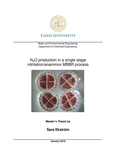
Picture on front page:<br />
1<br />
1. K1 carriers with <strong>anammox</strong> biofilm from the laboratory <strong>nitritation</strong>/<strong>anammox</strong><br />
<strong>MBBR</strong>.<br />
Postal address: Visit<strong>in</strong>g address: Telephone:<br />
P.O Box 124 Get<strong>in</strong>gevägen 60 +46 46-222 82 85<br />
SE-221 00 Lund. +46 46-222 00 00<br />
Sweden,<br />
Telefax:<br />
+46 46-222 45 26<br />
Web address:<br />
www.vateknik.lth.se
Summary<br />
Wastewaters conta<strong>in</strong> abundant nitrogen that causes eutrophication <strong>in</strong> the receiv<strong>in</strong>g<br />
recipient if not removed before the water is released <strong>in</strong>to nature. Common nitrogen<br />
removal is performed through nitrification and denitrification which are biologic<br />
<strong>process</strong>es. Microorganisms are utilised to convert <strong>in</strong>organic nitrogen compounds <strong>in</strong>to<br />
d<strong>in</strong>itrogen gas through different chemical reactions <strong>in</strong> there metabolism. Nitrous oxide,<br />
(<strong>N2O</strong>), can be an <strong>in</strong>termediate or end product <strong>in</strong> the metabolism of both nitrification and<br />
denitrification. <strong>N2O</strong> is a greenhouse gas, 320 times stronger than carbon dioxide (CO2).<br />
The gas is contribut<strong>in</strong>g to global warm<strong>in</strong>g and is also tak<strong>in</strong>g part <strong>in</strong> depletion of the<br />
protect<strong>in</strong>g ozone layer <strong>in</strong> the stratosphere. If large amounts of <strong>N2O</strong> are emitted from<br />
wastewater treatment facilities the problem with abundant nitrogen <strong>in</strong> aquatic<br />
environments is only transferred <strong>in</strong>to the atmosphere and <strong>N2O</strong> emissions should<br />
therefore be avoided.<br />
The energy demand for biologic nitrogen removal is high s<strong>in</strong>ce aeration is needed for the<br />
aerobe nitrification <strong>process</strong>. Denitrification requires an organic carbon source that often<br />
has to be added to the <strong>process</strong>, generally <strong>in</strong> the form of methanol. Burn<strong>in</strong>g of fossil fuels<br />
for energy coverage of the wastewater treatment plant and dur<strong>in</strong>g transportation of<br />
carbon source is lead<strong>in</strong>g to CO2 emissions with negative effects on the climate. If an<br />
additional organic carbon source is used <strong>in</strong> the denitrification <strong>process</strong> this will also<br />
contribute to <strong>in</strong>creased CO2 emissions from the wastewater treatment plant.<br />
Biological nitrogen removal through anaerobic ammonium oxidation (<strong>anammox</strong>) is a<br />
relatively new <strong>process</strong> solution <strong>in</strong> wastewater treatment. Anammox has the potential to<br />
replace common nitrogen removal of recycled <strong>in</strong>ternal wastewater streams with high<br />
strength of ammonium and low COD content. The bacteria responsible for the <strong>anammox</strong><br />
<strong>process</strong> are convert<strong>in</strong>g ammonium to d<strong>in</strong>itrogen gas with nitrite as electron acceptor<br />
mak<strong>in</strong>g a short cut <strong>in</strong> the nitrogen cycle. Only 50% of the <strong>in</strong>fluent nitrogen load <strong>in</strong> the<br />
form of ammonium has to be converted to nitrite by the nitrifiers and no additional<br />
carbon source is needed. This means that the <strong>process</strong> offers great sav<strong>in</strong>g possibilities,<br />
economical as well as environmental.<br />
Different system configurations are available for the <strong>anammox</strong> <strong>process</strong>, it can either be<br />
operated as a two <strong>stage</strong> <strong>process</strong> where <strong>nitritation</strong> and <strong>anammox</strong> are performed <strong>in</strong><br />
separate reactors, or <strong>in</strong> a s<strong>in</strong>gle <strong>stage</strong> <strong>process</strong> where both <strong>process</strong>es are tak<strong>in</strong>g part <strong>in</strong><br />
one reactor. A <strong>MBBR</strong> is suitable as a s<strong>in</strong>gle <strong>stage</strong> <strong>nitritation</strong>/<strong>anammox</strong> <strong>process</strong> s<strong>in</strong>ce a<br />
biofilm with an outer aerobe layer for the nitrifiers and one <strong>in</strong>ner anoxic layer for the<br />
<strong>anammox</strong> bacteria can develop. To allow the build up of a biofilm structure with<br />
different oxic layers the <strong>process</strong> has to be operated at low dissolved oxygen<br />
concentrations. Insufficient oxygenation <strong>in</strong> the nitrification <strong>process</strong> is known to enhance<br />
nitrous oxide emissions from ammonium oxidis<strong>in</strong>g bacteria. S<strong>in</strong>ce the s<strong>in</strong>gle <strong>stage</strong><br />
<strong>anammox</strong> <strong>process</strong> <strong>in</strong>volves <strong>nitritation</strong> at low dissolved oxygen concentrations the<br />
<strong>process</strong> might lead to significant <strong>N2O</strong> emissions.<br />
i
The ma<strong>in</strong> objective with this master thesis work was to study the <strong>production</strong> of nitrous<br />
oxide from a laboratory s<strong>in</strong>gle <strong>stage</strong> <strong>nitritation</strong>/ <strong>anammox</strong> <strong>MBBR</strong>. The <strong>N2O</strong><br />
measurements were performed onl<strong>in</strong>e <strong>in</strong> the water phase with a Clark–type<br />
microsensor developed by Unisense, Århus, Denmark. The reactor was operated at both<br />
<strong>in</strong>termittent and cont<strong>in</strong>uous aeration. The results from the experiments are summarised<br />
below:<br />
At <strong>in</strong>termittent aeration % reduction and removal rate <strong>in</strong> gN/m 2 d were <strong>in</strong> the range of<br />
47-59% and 0.9-1.1 gN/m 2 d respectively. As the reactor mode was shifted <strong>in</strong>to<br />
cont<strong>in</strong>uous aeration at a lower DO concentration both % reduction and removal rate <strong>in</strong><br />
gN/m 2 d was more stable and higher than dur<strong>in</strong>g <strong>in</strong>termittent aeration. % nitrogen<br />
reduction was between64-65% and the removal rate <strong>in</strong> the <strong>in</strong>terval of 1.3-1.6 gN/m 2 d.<br />
The <strong>MBBR</strong> system produced <strong>N2O</strong> regardless of operation mode. The n<strong>N2O</strong> <strong>production</strong><br />
was determ<strong>in</strong>ed through measurements of <strong>in</strong>itial accumulation of nitrous oxide <strong>in</strong> the<br />
water phase when aeration was turned off Intermittent aeration at high dissolved<br />
oxygen concentrations 3 mg/l was result<strong>in</strong>g <strong>in</strong> significant nitrous oxide <strong>production</strong><br />
rang<strong>in</strong>g from 6-11% of removed <strong>in</strong>organic nitrogen. Operation at cont<strong>in</strong>uous aeration<br />
yielded nitrous oxide emissions correspond<strong>in</strong>g to about 2-3% of removed <strong>in</strong>organic<br />
nitrogen. Higher <strong>process</strong> performance may be an explanation to smaller amounts of<br />
emitted <strong>N2O</strong>.<br />
Conclusions that can be made from the experiments are summarised below:<br />
• The s<strong>in</strong>gle <strong>stage</strong> <strong>nitritation</strong>/<strong>anammox</strong> system produced significant amounts of<br />
<strong>N2O</strong> with a m<strong>in</strong>imum <strong>production</strong> of 2% of removed <strong>in</strong>organic nitrogen.<br />
• Operat<strong>in</strong>g the <strong>MBBR</strong> at <strong>in</strong>termittent aeration with a DO of ~3 mg/l gave the<br />
highest <strong>N2O</strong> <strong>production</strong> with <strong>in</strong>itial and maximum <strong>production</strong>s of 6-11% and 10-<br />
30% respectively.<br />
• Smaller amounts of <strong>N2O</strong> were produced by the partial/<strong>nitritation</strong> <strong>anammox</strong><br />
system dur<strong>in</strong>g cont<strong>in</strong>uous operation at DO <strong>in</strong> the <strong>in</strong>terval 1-1.5 mg/l. The <strong>in</strong>itial<br />
<strong>N2O</strong> <strong>production</strong> was found to be 2-3% and the maximum <strong>N2O</strong> <strong>production</strong><br />
corresponded to 2-6%.<br />
• When the <strong>MBBR</strong> was exposed to a longer period of anoxic conditions both<br />
ammonium oxidation and <strong>N2O</strong> <strong>production</strong> ceased.<br />
• From results of mix<strong>in</strong>g with N2 gas dur<strong>in</strong>g the anoxic period it cannot be said<br />
with certa<strong>in</strong>ty that the <strong>N2O</strong> <strong>production</strong> is the same dur<strong>in</strong>g aeration and anoxic<br />
phase. The absolute number on overall <strong>N2O</strong> <strong>production</strong> for an operation mode<br />
(based on the measurements of <strong>N2O</strong> accumulat<strong>in</strong>g dur<strong>in</strong>g the anoxic phase) could<br />
be both overestimated or underestimated and should therefore be used as a<br />
comparative tool.<br />
ii
Acknowledgements<br />
I would like to express my gratitude to everyone who have <strong>in</strong>spired and supported me<br />
dur<strong>in</strong>g the work with my master thesis.<br />
My genu<strong>in</strong>e appreciation goes to:<br />
My supervisor Magnus Christenson at AnoxKaldnes for all guidance, support, shar<strong>in</strong>g off<br />
valuable knowledge and experiences, also for giv<strong>in</strong>g me the opportunity to get to know<br />
the fasc<strong>in</strong>at<strong>in</strong>g <strong>anammox</strong> <strong>process</strong>.<br />
My supervisor Professor Jes la Cour Jansen at Water and Environmental Enigneer<strong>in</strong>g<br />
Department of Chemical Eng<strong>in</strong>eer<strong>in</strong>g, Lund University for scientific guidance and<br />
encouragement, for all your valuable aspects on my work and always rem<strong>in</strong>d<strong>in</strong>g me of<br />
look<strong>in</strong>g <strong>in</strong>to th<strong>in</strong>gs from a wider perspective.<br />
To Lars H. Larsen at Unisense for all help and support with the microsensors.<br />
To everyone at AnoxKaldnes for all k<strong>in</strong>dness, support and for creat<strong>in</strong>g an <strong>in</strong>spir<strong>in</strong>g<br />
environment to work <strong>in</strong>. Special thanks to Maria Ekenberg for always answer<strong>in</strong>g my<br />
questions about the laboratory <strong>MBBR</strong> <strong>process</strong> and for all help <strong>in</strong> the laboratory. To<br />
Carol<strong>in</strong>a Shew Cammernäs for all patients and time while help<strong>in</strong>g me with the FIA<br />
analyses. To Stig Stork for all technical support.<br />
To David Gustavsson at VA SYD for exchang<strong>in</strong>g your ideas and knowledge about <strong>N2O</strong><br />
emissions <strong>in</strong> wastewater treatment <strong>process</strong>es.<br />
Last but not least I would like to thank my mother and my sister, Gustav and Helena for<br />
always encourag<strong>in</strong>g and support<strong>in</strong>g me.<br />
Thank you!<br />
iii
Glossary<br />
Aerobic – <strong>in</strong> the presence of oxygen <strong>in</strong> the form of O2<br />
Anaerobic – an oxygen free environment<br />
Anoxic – environment where oxygen is present as nitrite or nitrate<br />
Autotrophic – organism that can produce organic compounds from carbon dioxide with<br />
light or <strong>in</strong>organic chemical compound as energy source<br />
Carbon dioxide equivalent – is a measurement standard where the weight of a<br />
greenhouse gas released <strong>in</strong> to the atmosphere is converted <strong>in</strong>to the weight of carbon<br />
dioxide that would cause the same temperature rise <strong>in</strong> Earths ecosystem as the gas <strong>in</strong><br />
question<br />
Global warm<strong>in</strong>g potential – a measure of how much a given amount of a greenhouse<br />
gas would contribute to global warm<strong>in</strong>g <strong>in</strong> comparison with the same amount of carbon<br />
dioxide. The global warm<strong>in</strong>g potential of a greenhouse gas depends on (i) the absorption<br />
of <strong>in</strong>frared radiation of the gas, (ii) atmospheric life time, (iii) spectral location of<br />
absorb<strong>in</strong>g wavelengths, where the global warm<strong>in</strong>g potential of carbon dioxide is 1<br />
Heterotrophic – organism requir<strong>in</strong>g organic compounds as energy source<br />
Lithotrophic – organism us<strong>in</strong>g <strong>in</strong>organic nutrients to obta<strong>in</strong> energy<br />
Oxic – environment where oxygen is present<br />
Abbreviations<br />
Anammox – anaerobic ammonium oxidation<br />
AOB – ammonium oxidis<strong>in</strong>g bacteria<br />
ATP – adenos<strong>in</strong>e triphosphate<br />
Canon – completely autotrophic nitrogen removal over nitrite<br />
Deamox – denitrify<strong>in</strong>g ammonium oxidation<br />
DO – dissolved oxygen<br />
FIA – flow <strong>in</strong>jection analysis<br />
<strong>MBBR</strong> – mov<strong>in</strong>g biofilm bed reactor<br />
NH4 + – ammonium<br />
NO2 − – nitrite<br />
NO3 − – nitrate<br />
<strong>N2O</strong> – nitrous oxide<br />
ppm – part per million<br />
Sharon – S<strong>in</strong>gle reactor system for High rate Ammonium Removal Over Nitrite)<br />
v
Table of content<br />
Chapter 1 .................................................................................................................................... 1<br />
1. Introduction ............................................................................................................................ 1<br />
1.3 Objectives ............................................................................................................................................... 3<br />
1.4 Accomplishment and scope ............................................................................................................. 3<br />
Chapter 2 .................................................................................................................................... 5<br />
2. Background ............................................................................................................................. 5<br />
2.1 Biological nitrogen removal <strong>in</strong> wastewater treatment ......................................................... 5<br />
2.1.1 Nitrification ................................................................................................................................... 5<br />
2.1.2 Denitrification .............................................................................................................................. 6<br />
2.1.3 Anaerobic ammonium oxidation........................................................................................... 6<br />
2.2. Environmental factors ...................................................................................................................... 8<br />
2.2.1 Dissolved oxygen ......................................................................................................................... 8<br />
2.2.2 Temperature ................................................................................................................................. 9<br />
2.2.3 pH and alkal<strong>in</strong>ity ......................................................................................................................... 9<br />
2.2.4 Substrate...................................................................................................................................... 10<br />
2.2.5 Mix<strong>in</strong>g ........................................................................................................................................... 10<br />
2.3 Biofilm reactors ................................................................................................................................. 11<br />
2.3.1 Trickl<strong>in</strong>g filter ............................................................................................................................ 11<br />
2.3.2 Biofilters ...................................................................................................................................... 12<br />
2.3.3 Fluidised bed .............................................................................................................................. 12<br />
2.3.4 Mov<strong>in</strong>g bed reactor ................................................................................................................. 13<br />
2.3.5 Rotat<strong>in</strong>g disc .............................................................................................................................. 13<br />
2.4 Biofilm k<strong>in</strong>etics .................................................................................................................................. 13<br />
2.5 System configurations for nitrogen removal by <strong>anammox</strong> .............................................. 15<br />
2.5.1 Sharon/Anammox ................................................................................................................... 15<br />
2.5.2 Canon ............................................................................................................................................ 16<br />
2.5. 3 Deammonification .................................................................................................................. 17<br />
2.5.4 Deamox ........................................................................................................................................ 18<br />
2.5 <strong>N2O</strong> emissions from wastewater treatment ........................................................................... 18<br />
2.5.1 Nitrification as a source of <strong>N2O</strong> emissions ..................................................................... 19<br />
2.5.2 Denitrification as a source of <strong>N2O</strong> emissions ................................................................ 19<br />
2.5.3 Chemical <strong>production</strong> of <strong>N2O</strong> ................................................................................................ 20<br />
2.6 Microsensors ...................................................................................................................................... 22<br />
2.6.1 Nitrous oxide sensor ............................................................................................................... 22<br />
2.6.2 Nitrite biosensor....................................................................................................................... 23<br />
Chapter 3 .................................................................................................................................. 25<br />
3. Material and Methods .......................................................................................................... 25<br />
3.1 Partial <strong>nitritation</strong>/<strong>anammox</strong> laboratory <strong>MBBR</strong> . ................................................................. 25<br />
3.2 Reactor medium ................................................................................................................................ 26<br />
3.3 Analytical methods .......................................................................................................................... 27<br />
3.3 Cycle studies ....................................................................................................................................... 27<br />
3.3.1 Intermittent aeration .............................................................................................................. 27<br />
vii
3.3.2 Prolonged study, <strong>in</strong>termittent aeration........................................................................... 28<br />
3.3.3 Cont<strong>in</strong>uous aeration ................................................................................................................ 28<br />
3.4 Calibration of microsensors ......................................................................................................... 28<br />
3.5 Diffusivity tests of <strong>N2O</strong> ................................................................................................................... 30<br />
Chapter 4 .................................................................................................................................. 31<br />
4. Results .................................................................................................................................. 31<br />
4.1 Process performance ...................................................................................................................... 31<br />
4.3 <strong>N2O</strong> emissions from partial <strong>nitritation</strong>/<strong>anammox</strong> <strong>MBBR</strong> ................................................ 33<br />
4.3.2 Intermittent aeration. ............................................................................................................. 34<br />
4.3.2 Prolonged unaerated period. ............................................................................................... 35<br />
4.3.3 Cont<strong>in</strong>uous operation at DO ~1.5 mg/l ........................................................................... 36<br />
4.3.4 Cont<strong>in</strong>uous operation at DO ~1.0 mg/l ........................................................................... 37<br />
4.3.5 Effect of mix<strong>in</strong>g with N2 gas dur<strong>in</strong>g unaerated phase, cont<strong>in</strong>uous operation at<br />
DO ~1.0 mg/l and ~1.5 mg/l .......................................................................................................... 38<br />
4.4 NO2-N biosensor ............................................................................................................................... 40<br />
4.5 Diffusivity and stripp<strong>in</strong>g test of <strong>N2O</strong> ......................................................................................... 41<br />
Chapter 5 .................................................................................................................................. 44<br />
5. Discussion ............................................................................................................................. 44<br />
5.1 Process performance ...................................................................................................................... 44<br />
5.2 <strong>N2O</strong> <strong>production</strong> .................................................................................................................................. 44<br />
5.3 Measurements with NO2-N biosensor ...................................................................................... 47<br />
5.4 Diffusivity and stripp<strong>in</strong>g test of <strong>N2O</strong> ......................................................................................... 48<br />
6. Conclusions ........................................................................................................................... 51<br />
7. Future research .................................................................................................................... 53<br />
8. References ............................................................................................................................ 55<br />
Appendix A ............................................................................................................................... 63<br />
Calculation of concentrations <strong>in</strong> calibration solutions for <strong>N2O</strong> and NO2-N microsensors<br />
......................................................................................................................................................................... 63<br />
Appendix B ............................................................................................................................... 67<br />
Calculations of <strong>N2O</strong> emissions ............................................................................................................ 67<br />
Appendix C................................................................................................................................ 71<br />
Microsensor measurements ................................................................................................................ 71<br />
Appendix D ............................................................................................................................... 77<br />
Nitrogen grab samples ........................................................................................................................... 77<br />
Appendix E Scientific Article ..................................................................................................... 87<br />
viii
Chapter 1<br />
1. Introduction<br />
Nitrogen is one of the ma<strong>in</strong> build<strong>in</strong>g blocks <strong>in</strong> prote<strong>in</strong>s and is therefore a vital element<br />
for all liv<strong>in</strong>g organisms. The elemental form of nitrogen is made available to the<br />
biosphere through microbial fixation of d<strong>in</strong>itrogen gas which constitutes 79% of the<br />
atmosphere. Combustion of fossil fuels, the use of nitrogen <strong>in</strong> <strong>in</strong>dustry and fertilizers,<br />
waste and wastewater streams results <strong>in</strong> large amounts of anthropogenic nitrogen lost<br />
to nature. The human contribution to nitrogen cycl<strong>in</strong>g impacts the environment<br />
negatively through eutrophication of aquatic environments and emissions of<br />
nitrogenous compounds to the atmosphere. Release of b<strong>in</strong>ary nitrogenous gases<br />
contributes to the greenhouse effect and depletion of ozone layer with consequences on<br />
a global scale last<strong>in</strong>g for centuries.<br />
S<strong>in</strong>ce the start of the <strong>in</strong>dustrialisation human activity has <strong>in</strong>creased the emissions of<br />
greenhouse gases (carbon dioxide, chlorofluorocarbons, methane, ozone and nitrous<br />
oxide), to the atmosphere with about 30%, with global warm<strong>in</strong>g as a result (Liljenström<br />
& Kvarnbäck, 2007). In 2004 the global amount of anthropogenic emitted greenhouse<br />
gases corresponded to 49 billion tons carbon dioxide equivalents, (a measurement<br />
standard where the weight of a greenhouse gas released <strong>in</strong> to the atmosphere is<br />
converted <strong>in</strong>to the weight of carbon dioxide that would cause the same temperature rise<br />
<strong>in</strong> Earths ecosystem). Carbon dioxide stands for the greatest proportion of the emissions<br />
with 79% followed by methane and nitrous oxide contribut<strong>in</strong>g with 14% and 8%<br />
respectively, (Naturvårdsverket, 2009).<br />
Wastewater treatment plants produces greenhouse gases through; (i) burn<strong>in</strong>g of fossil<br />
fuels for coverage of the energy demand, (ii) transportation of chemicals for on-site<br />
usage and f<strong>in</strong>al disposal of solids, (iii) biologic treatment <strong>process</strong>es where nutrients,<br />
(organic matter, nitrogen and phosphorus) are removed through microbial <strong>process</strong>es.<br />
Biologic wastewater treatment <strong>process</strong>es are known to produce three of the major<br />
greenhouse gases carbon dioxide(CO2), methane (CH4) and nitrous oxide (<strong>N2O</strong>) (Bani<br />
Shahabadi et al., 2009). Nitrous oxide which is the strongest of these greenhouse gases is<br />
known to be produced dur<strong>in</strong>g nitrification and denitrification, <strong>process</strong>es used to remove<br />
nitrogen from the wastewater. The global warm<strong>in</strong>g potential of <strong>N2O</strong> is 320 times<br />
stronger than that of CO2. Release <strong>in</strong> to the atmosphere not only amplifies the warm<strong>in</strong>g<br />
of Earth’s surface temperature it also contributes to depletion of the ozone layer (Jacob,<br />
1999). Dur<strong>in</strong>g a thirty year period from 1990 to 2020 the <strong>N2O</strong> emissions associated with<br />
microbial nitrogen degradation of both treated and untreated wastewaters are<br />
estimated to <strong>in</strong>crease with 25% from 80 to 100 megaton carbon dioxide equivalents.<br />
Emissions from the post-consumer waste sector are approximately 1300 megaton<br />
carbon dioxide equivalents which corresponds to
stricter it might lead to elevated emissions of nitrous oxide from the biological removal<br />
<strong>process</strong>es. It is therefore of great importance to design and operate these <strong>process</strong>es to<br />
m<strong>in</strong>imise the emissions of nitrous oxide to the atmosphere.<br />
Wastewater treatment plants us<strong>in</strong>g biologic treatment <strong>process</strong>es for nutrient removal<br />
are produc<strong>in</strong>g excessive sludge giv<strong>in</strong>g rise to ammonium rich effluent from the<br />
anaerobic sludge digestion. This <strong>in</strong>ternal wastewater stream is recomb<strong>in</strong>ed with the<br />
<strong>in</strong>fluent of the treatment plant and corresponds to 15-20% of the total nitrogen load of<br />
the wastewater treatment plant (Fux et al., 2003). In the early 1990s a new biological<br />
treatment <strong>process</strong> for nitrogen removal through anaerobic ammonium oxidation<br />
(<strong>anammox</strong>) was discovered by research teams <strong>in</strong> Holland, Germany and Switzerland<br />
(Mulder et al., 1995, Hippen et al., 1997, Siegrist et al., 1998). The technology has turned<br />
out to be suitable for treatment of reject waters and other problematic wastewaters<br />
with a low COD/N ratio and high ammonium concentrations. The bacteria perform<strong>in</strong>g<br />
the microbial conversion of nitrite <strong>in</strong>to d<strong>in</strong>itrogen gas are strict anaerobe autotrophs<br />
and the <strong>process</strong> has the potential to replace conventional nitrification/denitrification of<br />
recirculated high strength ammonium streams with<strong>in</strong> the wastewater treatment plant<br />
(Strous et al., 1997). No additional carbon source is needed, the oxygen demand is<br />
reduced by 50% <strong>in</strong> the nitrify<strong>in</strong>g step and the aeration can thereby be strongly reduced<br />
(Jetten et al., 2001, Fux et al., 2002). This means that the <strong>process</strong> offers an opportunity to<br />
decrease the carbon footpr<strong>in</strong>t of the wastewater treatment plant <strong>in</strong> terms of sav<strong>in</strong>g<br />
possibilities of both additional carbon source and power consumption (Jetten et al.,<br />
2004). Further advantages with the <strong>anammox</strong> <strong>process</strong> is that the <strong>production</strong> of surplus<br />
sludge is m<strong>in</strong>imized and that high volumetric load<strong>in</strong>g rates can be obta<strong>in</strong>ed result<strong>in</strong>g <strong>in</strong><br />
reduced operational and <strong>in</strong>vestment costs (Abma et al., 2007). However there are<br />
doubts that the <strong>process</strong> could produce significant amounts of <strong>N2O</strong> gas with negative<br />
environmental impacts detract<strong>in</strong>g the <strong>process</strong> advantages.<br />
2
1.3 Objectives<br />
The aim with this master thesis was to estimate the <strong>N2O</strong> emissions from a partial<br />
<strong>nitritation</strong>/<strong>anammox</strong> laboratory mov<strong>in</strong>g bed biofilm reactor (<strong>MBBR</strong>) treat<strong>in</strong>g<br />
ammonium-rich synthetic wastewater. Measurements were carried out with a<br />
microsensor record<strong>in</strong>g the <strong>N2O</strong> concentration onl<strong>in</strong>e <strong>in</strong> the water phase, ma<strong>in</strong> objectives<br />
were:<br />
• To determ<strong>in</strong>e the <strong>N2O</strong> emission from the system under <strong>in</strong>itial operation<br />
conditions which were <strong>in</strong>termittent aeration at a dissolved oxygen, (DO),<br />
concentration of ~3 mg/l.<br />
• To evaluate <strong>N2O</strong> <strong>production</strong> when chang<strong>in</strong>g the operation mode <strong>in</strong>to cont<strong>in</strong>uous<br />
aeration to a lower DO concentration. Cont<strong>in</strong>uous operation at two different DO<br />
concentrations were tested ~1.5 mg/l and ~1.0 mg/l.<br />
• Determ<strong>in</strong>e how the <strong>N2O</strong> <strong>production</strong> was <strong>in</strong>fluenced dur<strong>in</strong>g a longer period of<br />
anoxic conditions.<br />
• Investigate whether the <strong>N2O</strong> accumulation observed <strong>in</strong> the water phase as<br />
aeration is turned off was due to term<strong>in</strong>ation of <strong>N2O</strong> stripp<strong>in</strong>g or if the <strong>N2O</strong><br />
<strong>production</strong> actually <strong>in</strong>creases dur<strong>in</strong>g the anoxic period.<br />
• To exam<strong>in</strong>e if a biosensor for onl<strong>in</strong>e measurements of NO2-N concentrations can<br />
replace traditional analyse methods for determ<strong>in</strong>ation of NO2-N dur<strong>in</strong>g this<br />
master thesis work.<br />
1.4 Accomplishment and scope<br />
The master thesis was based on both experimental work and a literature study.<br />
Laboratory studies were performed on an exist<strong>in</strong>g partial laboratory<br />
<strong>nitritation</strong>/<strong>anammox</strong> <strong>MBBR</strong> at AnoxKaldnes <strong>in</strong> Lund. The study took it’s start with a<br />
def<strong>in</strong>ition of the exist<strong>in</strong>g system and sett<strong>in</strong>g up the equipment for the microsensors used<br />
dur<strong>in</strong>g onl<strong>in</strong>e measurements. The laboratory work proceeded with measurement<br />
sessions where the <strong>N2O</strong> concentration was registered <strong>in</strong> the water phase at different<br />
operational conditions of the <strong>MBBR</strong>. S<strong>in</strong>ce no equipment for measurement of <strong>N2O</strong> <strong>in</strong> the<br />
off-gas were available experiments to estimate how much <strong>N2O</strong> that was stripped off<br />
from the water phase by diffusion and aeration were made.<br />
The collected data was analysed and the <strong>N2O</strong> <strong>production</strong> from the <strong>MBBR</strong> could be<br />
estimated with mass balance calculations of the system. The evaluation of the estimated<br />
<strong>N2O</strong> emission from the <strong>nitritation</strong>/<strong>anammox</strong> <strong>MBBR</strong> laboratory system was based on a<br />
literature study of <strong>N2O</strong> emissions <strong>in</strong> wastewater treatment. No calculations were made<br />
to estimate whether the <strong>anammox</strong> <strong>process</strong> is reduc<strong>in</strong>g or <strong>in</strong>creas<strong>in</strong>g the carbon footpr<strong>in</strong>t<br />
<strong>in</strong> comparison to common nitrogen removal <strong>process</strong>es.<br />
3
For simplicity a synthetic wastewater was used, this water may both be easier to<br />
degrade and not as complex as a normal wastewater which may impact the microbial<br />
performance.<br />
4
Chapter 2<br />
2. Background<br />
2.1 Biological nitrogen removal <strong>in</strong> wastewater treatment<br />
Nitrogen removal is one of the major tasks <strong>in</strong> wastewater treatment. Biologic nitrogen<br />
removal is the most efficient way to elim<strong>in</strong>ate nitrogen from the wastewater and a<br />
variety of system configurations like activated sludge plants with suspended growth,<br />
biofilters designed for attached growth and comb<strong>in</strong>ations of the two have been<br />
developed. These systems are built on the knowledge of microbial nitrogen cycl<strong>in</strong>g<br />
where nitrogen compounds like NH4+, NO2 − and NO3 − are removed by conversion <strong>in</strong>to<br />
elemental N2 gas released to the atmosphere, see Figure 1. The well known nitrification<br />
and denitrification <strong>process</strong>es are commonly used to achieve satisfactory nitrogen<br />
removal. Today anaerobic ammonium oxidation, a relatively new technology for<br />
nitrogen removal is also <strong>in</strong> use at several places.<br />
Figure 1. Major biological transformations of nitrogen <strong>in</strong> wastewater treatment. (Kampschreur et<br />
al., 2009).<br />
2.1.1 Nitrification<br />
Nitrification is oxidation of ammonium <strong>in</strong>to nitrate under aerobic conditions, the<br />
<strong>process</strong> occurs <strong>in</strong> two separated reaction steps, each <strong>in</strong>volv<strong>in</strong>g different species of<br />
bacteria. The nitrifiers are chemo-lithoautotrophs which means that they use carbon<br />
dioxide or carbonate as carbon source and <strong>in</strong>organic nitrogen is used for both energy<br />
supply and cellular growth (Gray, 2004). In the first <strong>nitritation</strong> step ammonium<br />
oxidis<strong>in</strong>g species like Nitrosomonas and Nitrosospira oxidises ammonium <strong>in</strong>to nitrite:<br />
5
NH 1.5O NO 2H 2H O (2.1.1)<br />
The <strong>in</strong>termediate of the nitrification <strong>process</strong> (NO2 − ) is then further oxidised <strong>in</strong>to nitrate<br />
by nitrite oxidisers:<br />
NO 0.5O NO <br />
<br />
(2.1.2)<br />
The nitratation step is performed by species like Nitrobacter and Nitrococcus (Prescott<br />
et al., 2005). The overall nitrification reaction can be described by:<br />
NH 2O NO 2H 2H O (2.1.3)<br />
Energy ga<strong>in</strong>ed by the bacteria dur<strong>in</strong>g nitrification is used <strong>in</strong> the electron transport cha<strong>in</strong><br />
to make adenos<strong>in</strong>e triphosphate, (ATP is the energy currency of the cell mak<strong>in</strong>g<br />
chemical transport possible), (Prescott et al., 2005). Nitrify<strong>in</strong>g bacteria are slow<br />
growers s<strong>in</strong>ce nitrification <strong>process</strong>es gives a low energy yield, (see Table 1) and the<br />
nitrifiers have to oxidise large amount of <strong>in</strong>organic material for their growth and<br />
re<strong>production</strong>, (Prescott et al., 2005).<br />
2.1.2 Denitrification<br />
Denitrification is nitrate respiration under anoxic conditions carried out by a large<br />
number of different heterotrophic bacteria. Nitrate is used to oxidate organic carbon<br />
<strong>in</strong>to elemental nitrogen and carbon dioxide:<br />
NO organic carbon N CO (2.1.4)<br />
Denitrify<strong>in</strong>g bacteria need an easily biodegradable carbon source and their demand for<br />
removal of one gram of nitrogen corresponds to 3-6 grams of chemical oxygen demand,<br />
(COD). If the COD/N ratio of the wastewater becomes too low an additional carbon<br />
source like methanol must be added <strong>in</strong> order to achieve nitrogen removal of nitrate<br />
through denitrification (Gillberg et al., 2003)<br />
Pseudomonas, Paraccocus, and Bacillus are examples of bacteria denitrifiy<strong>in</strong>g under<br />
anoxic conditions. Most denitrifiers are facultative anaerobes which means that they<br />
generally respire with oxygen as f<strong>in</strong>al electron acceptor, this s<strong>in</strong>ce the oxygen route<br />
yields more energy than nitrate respiration (Prescott et al., 2005).<br />
2.1.3 Anaerobic ammonium oxidation<br />
Anammox bacteria are obligate anaerobe autotrophs us<strong>in</strong>g <strong>in</strong>organic nitrogen and<br />
carbon for energy supply and growth, the <strong>process</strong> offers a short cut <strong>in</strong> the nitrogen cycle<br />
as illustrated <strong>in</strong> Figure 1(Jetten et al., 1999). Ammonium is converted <strong>in</strong>to d<strong>in</strong>itrogen gas<br />
with nitrite as electron acceptor (2.1.6), hydraz<strong>in</strong>e (N2H4) and hydroxylam<strong>in</strong>e (NH2OH)<br />
6
are <strong>in</strong>termediates <strong>in</strong> the chemical reaction. This reaction is the catabolic and energy<br />
supply<strong>in</strong>g part <strong>in</strong> <strong>anammox</strong> metabolism, it has to be carried out 15 times to fix one<br />
molecule of carbon dioxide with nitrite as electron donor <strong>in</strong> the cellular synthesis or<br />
anabolism (2.1.7) which produces nitrate (van Niftrik et al., 2004).<br />
<br />
NH NO N 2H O (2.1.6)<br />
CO 2NO <br />
H O CH O 2NO (2.1.7)<br />
Broda, (1977), predicted this microbial <strong>process</strong> through thermodynamic calculations for<br />
over thirty years ago. The <strong>anammox</strong> <strong>process</strong> was discovered <strong>in</strong> the early n<strong>in</strong>eties <strong>in</strong> a<br />
rotat<strong>in</strong>g-disk plant treat<strong>in</strong>g landfill leachate at Mechernich, Germany (Rosenw<strong>in</strong>kel &<br />
Cornelius, 2005). Mulder et al. also identified the <strong>anammox</strong> <strong>process</strong> <strong>in</strong> a denitrify<strong>in</strong>g<br />
fluidised bed reactor <strong>in</strong> Deltft, the Netherlands, at about the same time (Mulder et al.,<br />
1995). Total stoichiometry of the <strong>anammox</strong> <strong>process</strong> has been estimated by Strous et al.,<br />
(1998):<br />
1NH <br />
<br />
1.32NO 0.066HCO <br />
<br />
0.13H <br />
1.02 N 0.26NO <br />
<br />
0.066CH2O . N . 2.03 H O. (2.1.7)<br />
The bacterium perform<strong>in</strong>g the <strong>anammox</strong> reaction has been identified as a new member<br />
of the order Planctomycete (Strous et al., 1999). Until now totally five <strong>anammox</strong> genera<br />
have been identified, four from enriched wastewater sludge: Kuenenia, Brocadia,<br />
Anammoxoglobus and Jettenia, the fifth genera of <strong>anammox</strong> bacteria Scal<strong>in</strong>dua is often<br />
found <strong>in</strong> mar<strong>in</strong>e environments (Jetten et al., 2009).<br />
Planctomycetes are gram-negative bacteria with phenotypic properties such as absence<br />
of peptidoglycan <strong>in</strong> the cell wall, budd<strong>in</strong>g re<strong>production</strong> and <strong>in</strong>ternal cell<br />
compartmentalisation due to two membranes on the <strong>in</strong>side of the cell wall (Prescott et<br />
al., 2005). Anammox bacteria are characterized by their deep red colour and ability to<br />
form bio-films (Abma et al., 2006). Anammox cell structure is divided <strong>in</strong>to three<br />
compartments. The outer region closest to the cell wall called the paryphoplasm<br />
encloses the second compartment which is the riboplasm. The riboplasm conta<strong>in</strong>s the<br />
nucleoid and the <strong>anammox</strong>osome, the third compartment where <strong>anammox</strong> catabolism<br />
takes place, see Figure 2. All compartments are separated by bilayer membranes<br />
constituted of impermeable and high density ladderane lipids (van Niftrik et al., 2004).<br />
The higher membrane density is of importance to the <strong>anammox</strong> bacteria of two reasons,<br />
one that it creates an electro potential force driv<strong>in</strong>g the ATP synthesis, and two it keeps<br />
the toxic <strong>in</strong>termediates from the <strong>anammox</strong> <strong>process</strong> hydroxylam<strong>in</strong>e and hydraz<strong>in</strong>e <strong>in</strong>side<br />
the <strong>anammox</strong>osome (van Niftrik et al., 2004).<br />
7
Figure 2. Illustration of <strong>anammox</strong> bacteria. (Adapted from van Niftrik et al., 2004).<br />
Anammox bacteria are extremely slow growers, their doubl<strong>in</strong>g time has been found to<br />
11 days <strong>in</strong> activated sludge (Strous et al., 1999). However it might be possible to<br />
<strong>in</strong>crease this doubl<strong>in</strong>g rate with optimal operation conditions s<strong>in</strong>ce other researchers<br />
have found a much shorter doubl<strong>in</strong>g rate of 3.6-5.4 days for <strong>anammox</strong> bacteria <strong>in</strong> a upflow<br />
fixed-bed biofilm column reactor (Tsushima et al., 2007).<br />
The microbial <strong>process</strong>es and chemical reactions of nitrification, denitrification and<br />
<strong>anammox</strong> are summarized <strong>in</strong> Table 1.<br />
Table 1. Microbial <strong>process</strong>es and chemical reactions tak<strong>in</strong>g part <strong>in</strong> the nitrogen cycle showed <strong>in</strong><br />
Figure 1.<br />
Energy yield<br />
ΔG ̊’ eq.<br />
Process<br />
Chemical reaction<br />
+<br />
kJ/mol NH 4<br />
Nitritation: NH 1.5O NO 2H H O -271 (2.1.1)<br />
Nitratation: NO 0.5O <br />
<br />
NO -72.8 (2.1.2)<br />
Nitrification: NH 2O NO 2H H O - (2.1.3)<br />
Denitrification: NO org. carbon N 2CO <br />
-<br />
(2.1.4)<br />
Anammox: NH <br />
NO N 2H O -358.8 (2.1.6)<br />
2.2. Environmental factors<br />
Dissolved oxygen, temperature, pH, substrate concentrations and turbulence are abiotic<br />
conditions that are of great importance for the growth and survival of the microbiology<br />
<strong>in</strong> a wastewater treatment system.<br />
2.2.1 Dissolved oxygen<br />
Depend<strong>in</strong>g on the electron donor <strong>in</strong> the respiratory cha<strong>in</strong> of the microorganism can be<br />
limited or <strong>in</strong>hibited by either to low or to high DO concentrations. It is the oxygen<br />
concentration with<strong>in</strong> the biofilm experienced by the bacteria that is of importance for<br />
the wellness of the organism (Henze et al., 1997).<br />
Nitrify<strong>in</strong>g bacteria utilis<strong>in</strong>g oxygen as electron donor are sensitive for too low oxygen<br />
concentrations and are limited by DO concentrations
m<strong>in</strong>imum concentration of 2 mg/l should be ma<strong>in</strong>ta<strong>in</strong>ed (Gray, 2004). The nitrify<strong>in</strong>g rate<br />
<strong>in</strong>creases up to DO levels of 3-4 mg/l, (Metcalf & Eddy). All figures given here yields for<br />
DO concentrations <strong>in</strong> the water bulk phase of activated sludge <strong>process</strong>es, higher DO<br />
concentrations are needed to satisfy the microbial oxygen demand <strong>in</strong> biofilm <strong>process</strong>es.<br />
This s<strong>in</strong>ce the oxygen concentration <strong>in</strong> the biofilm depends on diffusion of oxygen from<br />
the water phase <strong>in</strong>to the biofilm which is further expla<strong>in</strong>ed <strong>in</strong> chapter 2.4.<br />
Both denitrification and <strong>anammox</strong> <strong>process</strong>es are <strong>in</strong>hibited by oxygen. Denitrification has<br />
been observed to be <strong>in</strong>hibited at DO concentrations above 0.2 mg/l (Metcalf & Eddy,<br />
2003) and <strong>anammox</strong> organisms are reversibly <strong>in</strong>hibited by DO concentrations as low as<br />
2 µmole/l or 0.032 mg/l, (Jetten et al., 1998).<br />
2.2.2 Temperature<br />
The temperature impacts the structure of the microbial community and is crucial for<br />
growth and reaction rates <strong>in</strong> the system. Microbial reactions are often dependent on<br />
enzyme-catalysed reactions that <strong>in</strong>crease <strong>in</strong> velocity at higher temperatures. When the<br />
time for a reaction to be catalysed is shortened the metabolism is more active and the<br />
microorganism is allowed to grow faster (Prescott et al., 2005). Temperature does also<br />
impact non viable factors like settl<strong>in</strong>g characteristics, gas solubility and transfer rates<br />
(Gray, 2004).<br />
Nitrification can be operated <strong>in</strong> a temperature <strong>in</strong>terval of 0-40 °C with a temperature<br />
optimum between 30-35 °C (Gray, 2004). Denitrify<strong>in</strong>g bacteria are less sensitive to<br />
temperature than nitrifiers and denitrification can take place <strong>in</strong> a temperature <strong>in</strong>terval<br />
from 2-75 °C with an optimum around 30 °C (Pierzynski et al., 2005)<br />
Anammox bacteria are active <strong>in</strong> temperature range from 6-43 °C with an optimum at 30<br />
̊C (Anammox onl<strong>in</strong>e).<br />
2.2.3 pH and alkal<strong>in</strong>ity<br />
pH, which is the measurement of a solutions acidity or alkal<strong>in</strong>ity, is another important<br />
environmental factor that impacts the growth rate of the microbial community. S<strong>in</strong>ce pH<br />
is def<strong>in</strong>ed as the <strong>in</strong>verse logarithm of H + ions <strong>in</strong> solution a change of one pH unit<br />
corresponds to a tenfold <strong>in</strong>crease <strong>in</strong> the activity of H + ions. Each bacteria species have a<br />
pH growth range and optimum.<br />
Nitrification consumes alkal<strong>in</strong>ity s<strong>in</strong>ce two moles of OH − are used per mole ammonium<br />
oxidised. Nitrification is favoured by mild alkal<strong>in</strong>e conditions with pH optimum <strong>in</strong> the<br />
range of pH 8.0-8.4 (Gray, 2004). The nitrification rate is significantly decl<strong>in</strong>ed by low<br />
pH values
Denitrification produces alkal<strong>in</strong>ity and pH is generally raised by the <strong>process</strong>. pH<br />
optimum is rang<strong>in</strong>g from 7-9 depend<strong>in</strong>g on local conditions (Henze et al., 1997).<br />
Cell synthesis <strong>in</strong> the <strong>anammox</strong> reaction is <strong>in</strong>creas<strong>in</strong>g pH and the <strong>process</strong> is active <strong>in</strong> a pH<br />
range from 6.5-9 with an optimum around 8 (Egli et al., 2001).<br />
2.2.4 Substrate<br />
Nitrify<strong>in</strong>g, denitrify<strong>in</strong>g and <strong>anammox</strong> bacteria are all dependent on different substrates<br />
for energy and cellular growth as discussed above. The ability to utilise their substrate<br />
varies between bacterial species. This implies that a species with high aff<strong>in</strong>ity for its<br />
substrate will be better at utilis<strong>in</strong>g the substrate at low concentration and therefore<br />
outcompete species with lower aff<strong>in</strong>ity for the substrate. The half saturation constant,<br />
which is the substrate concentration when the growth rate is half of maximum, is often<br />
used to compare how well adapted different microorganisms are to their substrates.<br />
The half saturation constant or Ks value for ammonium oxidisers <strong>in</strong> a nitrify<strong>in</strong>g biofilm<br />
airlift reactor was found to correspond to a NH4-N concentration of 11 mg/l. And the<br />
microorganisms were <strong>in</strong>hibited by NH4-N concentrations of 3300 ±1400 mg/l. (Carvallo<br />
et al., 2002)<br />
Denitrification rate and capacity is very dependent on available organic carbon source.<br />
External carbon sources like methanol, ethanol and acetic acid are readily biodegradable<br />
and give much higher denitrification rates than denitrification with organic compounds<br />
found <strong>in</strong> the waste water (Ødegaard, 1993).<br />
Anammox bacteria have high aff<strong>in</strong>ity for their substrates ammonia and nitrite, the Ks<br />
values are below chemical detection level (
2.3 Biofilm reactors<br />
Biofilm reactors can be used for nutrient removal <strong>in</strong> wastewater treatment and are<br />
commonly used <strong>in</strong> biological nitrogen removal. Bacteria with the ability to adhere to<br />
solid surfaces are colonis<strong>in</strong>g and grow<strong>in</strong>g <strong>in</strong> high concentrations <strong>in</strong> a biofilm attached to<br />
a fixed surface. The carrier material can be solid or free mov<strong>in</strong>g made out of stone, wood<br />
or plastic. Biofilm thickness varies with the hydrodynamics and growth conditions of the<br />
system, (Metcalf & Eddy, 2003). The fixed polymer film formed by the bacteria protects<br />
them from toxics and be<strong>in</strong>g washed out of the system (Henze et al., 1997).<br />
Figure 3. Illustration of different types of bioflim reactors. (Adapted from Ødegaard, 1993).<br />
Biofilters are designed to achieve high and efficient nutrient removal rates <strong>in</strong> compact<br />
and energy efficient systems. Operat<strong>in</strong>g conditions should be such that transfer rates of<br />
substrates from the water bulk phase to the microbial community assures efficient<br />
removal rates and development of a biofilm thickness satisfy<strong>in</strong>g the microbial demands<br />
<strong>in</strong> a certa<strong>in</strong> biologic <strong>process</strong>. This makes different available biofilm technologies suitable<br />
for varied microbial <strong>process</strong>es. Figure 3 illustrates some of the available biofilm<br />
technologies shortly described <strong>in</strong> the follow<strong>in</strong>g text.<br />
2.3.1 Trickl<strong>in</strong>g filter<br />
Trickl<strong>in</strong>g filters are biological reactors where the wastewater is spr<strong>in</strong>kled over a filter<br />
bed at the top. The water is then allowed to percolate through a fixed bed material made<br />
out of stone or plastic. Volumetric flow rates are controll<strong>in</strong>g the biofilm thickness and<br />
11
aeration takes place through self drag from bottom to top of the filter (Henze et al.,<br />
1997). S<strong>in</strong>ce the wastewater is spr<strong>in</strong>kled over and percolated through the filter media<br />
there is little hydraulic control of the biofilm thickness result<strong>in</strong>g <strong>in</strong> uneven growth<br />
throughout the filter. This causes local clogg<strong>in</strong>g that h<strong>in</strong>ders free flow of water and air<br />
through the filter result<strong>in</strong>g <strong>in</strong> decreased nutrient removal rate. Modern fill<strong>in</strong>g materials<br />
<strong>in</strong> plastic have a specific fill<strong>in</strong>g area of about 100-250 m 2 /m 3 while the carry<strong>in</strong>g material<br />
<strong>in</strong> older treatment plants often is crushed stone or pumice that only has a specific area of<br />
40-60 m 2 /m 3 , (Gillberg et al., 2003).<br />
2.3.2 Biofilters<br />
The carrier material <strong>in</strong> these filters can be either a granulated media or corrugated<br />
sheets. In the granulated reactor wastewater passes through a stationary filter bed made<br />
out of sand or plastic beads, the filter media is aerated from the bottom <strong>in</strong> the aerobic<br />
version. The specific area of the filter media is high and ranges from 1000-1200 m 2 /m 3 ,<br />
the effective area is however not this high s<strong>in</strong>ce only 50% of the reactor volume is filled<br />
with the carrier material (Ødegaard, 1993). This reactor clogs easily and has to be<br />
backwashed. Clogg<strong>in</strong>g and substrate decrease from top to bottom <strong>in</strong> the reactor rules<br />
out efficient nutrient removal throughout the whole reactor volume. The second type of<br />
media is a stationary carrier material constituted of plastic sheets that are welded<br />
together <strong>in</strong> cubes, the specific area of these filters ranges from 150-200 m 2 /m 3 . The<br />
system is aerated from the bottom with blower systems and has to be backwashed at<br />
<strong>in</strong>tervals to prevent clogg<strong>in</strong>g (Ødegaard, 1993).<br />
2.3.3 Fluidised bed<br />
In a fluidised bed the biofilm grows on sand gra<strong>in</strong>s with a size of 0.4-0.5 mm. To keep the<br />
sand gra<strong>in</strong>s <strong>in</strong> suspension at all times wastewater is pumped through the bottom of the<br />
reactor at a high constant flow rate. The turbulence created from high volumetric flow<br />
rates pass<strong>in</strong>g through the reactor implies great shear forces and very th<strong>in</strong> biofilms. With<br />
bed depths rang<strong>in</strong>g from 3 to 4 m a specific surface area of 1000 m 2 /m 3 can be achieved<br />
(Metcalf & Eddy, 2004). High turbulence <strong>in</strong> comb<strong>in</strong>ation with very high contact area<br />
between microorganisms and wastewater assures efficient substrate transmission and<br />
high conversion rates. The draw back with this <strong>process</strong> design <strong>in</strong> nitrification is that<br />
oxygen transfer rates to the water phase are too slow to ma<strong>in</strong>ta<strong>in</strong> sufficient oxygen<br />
concentrations for microbial activity (Gillberg et al., 2003) S<strong>in</strong>e the biofilm is very th<strong>in</strong> <strong>in</strong><br />
this reactor configuration it does not allow development of a biofilm with layers of<br />
different oxygen concentration. This reactor type can there for not comb<strong>in</strong>e microbial<br />
communities with different dissolved oxygen demands. Recirculation is necessary to<br />
ma<strong>in</strong>ta<strong>in</strong> the high fluid velocity.<br />
12
2.3.4 Mov<strong>in</strong>g bed reactor<br />
Another way to design a compact biofilm <strong>process</strong> is to use a suspended <strong>in</strong>ert carrier that<br />
moves freely with<strong>in</strong> the reactor. The first carrier materials were small polyethylene<br />
(density 0.95 g/cm 3 ) cyl<strong>in</strong>ders with a cross <strong>in</strong> side provid<strong>in</strong>g the microorganisms with a<br />
protected surface to grow on. The carriers are kept <strong>in</strong> motion by aeration or mechanical<br />
stirr<strong>in</strong>g, a sieve <strong>in</strong> the outlet keeps the mov<strong>in</strong>g carriers <strong>in</strong> the reactor. The reactor does<br />
not clog and there is no need for backwash<strong>in</strong>g or biomass recycl<strong>in</strong>g. (Ødegaard et al.,<br />
1994). Different shapes and sizes of the carrier material provides an effective specific<br />
area rang<strong>in</strong>g from 220 -1200 m 2 /m 3 (AnoxKaldnes, 2009). Biofilm thickness depends on<br />
carrier design and hydraulic conditions <strong>in</strong> the reactor. If a stagnant lam<strong>in</strong>ar layer is<br />
formed around the carrier material this will <strong>in</strong>crease the diffusional resistance that is<br />
limit<strong>in</strong>g <strong>in</strong> biofilm <strong>process</strong>es. The mov<strong>in</strong>g bed technology can also be comb<strong>in</strong>ed with the<br />
activated sludge <strong>process</strong> result<strong>in</strong>g <strong>in</strong> higher removal rates and more compact systems.<br />
2.3.5 Rotat<strong>in</strong>g disc<br />
Rotat<strong>in</strong>g filters are constituted of flat discs often made out of plastic, 2-3 meters <strong>in</strong><br />
diameter mounted <strong>in</strong> rows on a horizontal shaft. The filter medium that is semisubmerged<br />
is alternately rotated through the water phase at right angles to the flow.<br />
The filters are 10-20 mm thick, spaced about 20 mm apart and have an active surface<br />
area of about 150-200 m 2 /m 3 (Gray N, 2004). Rotation of the filter discs keeps the<br />
biofilm oxygenated and the motion creates an efficient contact between the water phase<br />
and biofilm. Revolution speed of the filter is controll<strong>in</strong>g the biofilm thickness (Henze et<br />
al., 1997).<br />
2.4 Biofilm k<strong>in</strong>etics<br />
The k<strong>in</strong>etics of substrate conversion <strong>in</strong> a biofilm reactor is dependent of the reactor<br />
configuration that decides the biofilm structure and of available nutrients <strong>in</strong> the<br />
wastewater. Substrates <strong>in</strong> the water bulk phase are converted to biomass, energy and<br />
end products through cellular metabolism <strong>in</strong> the bacteria. The mass balance for an<br />
<strong>in</strong>f<strong>in</strong>itely small section of the biofilm is described by:<br />
(2.4.1)<br />
(2.4.2)<br />
where: Q is the volumetric flow, (dimension L -3 ∙T -1 ), C is the concentration, (dimension<br />
M∙L -3 ), r describes the biological growth rate, (dimension M∙L -3 ∙ T -1 ) and V is the reactor<br />
volume, (dimension L -3 ), (Warfv<strong>in</strong>ge, 2008).<br />
The substrate conversion rate <strong>in</strong> a biofilm reactor is dependent on three ma<strong>in</strong><br />
mechanisms, the diffusion resistance of substrates from the well mixed water bulk phase<br />
13
to the liquid film, diffusion of substrates through the biofilm and substrate turnover <strong>in</strong><br />
the cellular mass (Ødegaard, 1993), see Figure 4. The diffusion dependent transport of<br />
substrate from the liquid bulk and the diffusion with<strong>in</strong> the biofilm is driven by a<br />
concentration gradient. The substrate concentration profile decreases with biofilm<br />
depth and has a downward curvature due to the substrate utilisation rate illustrated <strong>in</strong><br />
Figure 4, (Henze et al., 1997). Conversion rate on cellular level is dependent on<br />
enzymatic <strong>process</strong>es. Available amount of enzymes handl<strong>in</strong>g the specific substrate will<br />
decide how fast the conversion takes place. When substrate concentrations are low, the<br />
accessible substrate S is the rate limit<strong>in</strong>g factor and the rate equation is said to be of first<br />
order with respect to S, see (2.4.3). At high substrate concentrations the substrate<br />
turnover is limited by the amount of available enzymes. The reaction rate is now of zero<br />
order s<strong>in</strong>ce it is <strong>in</strong>dependent of the substrate concentration, see (2.4.4), (Warfv<strong>in</strong>ge,<br />
2008).<br />
First and zero order approximations are given by the follow<strong>in</strong>g equations:<br />
, <br />
<br />
· <br />
<br />
(2.4.3)<br />
, <br />
<br />
(2.4.4)<br />
where: rv,s describes the biological growth rate <strong>in</strong> a certa<strong>in</strong> volume of biofilm at a certa<strong>in</strong><br />
substrate concentration, (dimension M∙ L -3 ∙ T -1 ), µmax is the maximum specific growth<br />
rate, (dimension T -1 ), XB is the concentration of biomass, (dimension M∙L -3 ), Ymax gives<br />
the maximum yield constant, (dimension MXB∙Ms -1 ) and Ks is the saturation constant for<br />
the substrate, (dimension M∙L -3 ), (Henze et al., 1997).<br />
Figure 4. Schematic overview of substrate transport from liquid bulk phase to microorganisms<br />
grow<strong>in</strong>g on carrier material. The concentration gradient profile <strong>in</strong> the biofilm depends on<br />
transport <strong>in</strong>to the biofilm and substrate utilisation rate <strong>in</strong> the film. (Adapted from Metcalf & Eddy,<br />
2003, and Warfv<strong>in</strong>ge, 2008).<br />
14
To enable efficient nutrient removal the hydraulic conditions should prevent the buildup<br />
of a lam<strong>in</strong>ar layer and the contact surface between water phase and biofilm should be<br />
as large as possible (Metcalf & Eddy, I. 2003).<br />
2.5 System configurations for nitrogen removal by <strong>anammox</strong><br />
Nitrogen removal by <strong>anammox</strong> can be implemented either as a two <strong>stage</strong> or one <strong>stage</strong><br />
system. 50% of the <strong>in</strong>fluent ammonium is oxidised to nitrite by nitrify<strong>in</strong>g bacteria <strong>in</strong><br />
both cases. In a two <strong>stage</strong> system this conversion takes place <strong>in</strong> a <strong>nitritation</strong> reactor<br />
followed by an <strong>anammox</strong> reactor where the oxidation of ammonium <strong>in</strong>to d<strong>in</strong>itrogen gas<br />
with nitrite takes place. In s<strong>in</strong>gle <strong>stage</strong> technology both <strong>process</strong>es takes place <strong>in</strong> the<br />
same reactor (Abma et al., 2007). S<strong>in</strong>ce the <strong>anammox</strong> <strong>process</strong> was discovered by<br />
different research teams and <strong>in</strong> slightly diverse environments the system configurations<br />
evolved have been given different names but are <strong>in</strong> practice quite similar. Ma<strong>in</strong><br />
differences are reactor configuration and operational mode. Some of the available<br />
<strong>anammox</strong> <strong>process</strong>es are shortly described <strong>in</strong> this chapter.<br />
2.5.1 Sharon/Anammox<br />
A Sharon (s<strong>in</strong>gle reactor system for high rate ammonium removal over nitrite)<br />
reactor followed by an <strong>anammox</strong> reactor is a possible system configuration to achieve<br />
nitrogen removal with <strong>anammox</strong> bacteria. The Sharon <strong>process</strong> is used to nitrify 50% of<br />
the <strong>in</strong>fluent ammonium to nitrite. The effluent from the Sharon reactor is then used as<br />
feed for the <strong>anammox</strong> reactor where nitrite and ammonium is converted to elemental<br />
nitrogen, see Figure 5, (Stowa, 2009).<br />
Figure 5. Sharon/Anammox <strong>process</strong> scheme.<br />
To achieve partial nitrification to only 50% the Sharon reactor is operated <strong>in</strong> a manner<br />
that benefits the ammonium oxidizers, wash<strong>in</strong>g out the nitrite oxidizers from the system<br />
(van Dongen et al., 2001). This is obta<strong>in</strong>ed by operation above 25 ̊C, keep<strong>in</strong>g the sludge<br />
15
age equal to the hydraulic retention time, and by controll<strong>in</strong>g the pH to get the desired<br />
ammonium/nitrite ratio:<br />
NH HCO 0.75O 0.5NH 0.5NO CO 1.5H O (2.5.1)<br />
The effluent from the Sharon reactor is then feed<strong>in</strong>g the <strong>anammox</strong> <strong>process</strong> that converts<br />
nitrite and ammonium to elemental nitrogen accord<strong>in</strong>g to eq. (2.1.7).<br />
Some nitrate is formed <strong>in</strong> the <strong>anammox</strong> <strong>process</strong> as biomass is formed from <strong>in</strong>organic<br />
carbon with nitrite as electron donor (van Dongen et al., 2001).<br />
2.5.2 Canon<br />
The Canon <strong>process</strong> (completely autotrophic nitrogen removal over nitrite) is a s<strong>in</strong>gle<br />
<strong>stage</strong> <strong>process</strong> for nitrogen removal with ammonium oxidisers and <strong>anammox</strong> bacteria,<br />
(Third et al., 2001), see Figure 6 for system description.<br />
Figure 6. Canon <strong>process</strong> scheme<br />
The Canon reactor has to be oxygen limited to allow the co-existence of both ammonium<br />
oxidisers and <strong>anammox</strong> bacteria <strong>in</strong> the same environment. Ammonium oxidation <strong>in</strong>to<br />
nitrite is performed under oxygen limitation by aerobic ammonium oxidisers eq. (2.5.3).<br />
Anammox bacteria are oxidis<strong>in</strong>g ammonium with nitrite <strong>in</strong>to d<strong>in</strong>itrogen gas eq. (2.5.4).<br />
The result<strong>in</strong>g over all chemical reaction for the Canon <strong>process</strong> is described by eq. (2.5.5),<br />
(Third et al., 2005).<br />
Partial nitrification:NH 1.5O NO 2H H O (2.5.3)<br />
Anammox: NH 1.3NO N 0.26NO 2H O (2.5.4)<br />
Canon <strong>process</strong>: NH 0.85O 0.4N 0.13NO 1.3H O 1.4H (2.5.5)<br />
16
The Canon <strong>process</strong> is often implemented with granular sludge and it is important that<br />
large biomass flocs with decreas<strong>in</strong>g oxygen gradient with<strong>in</strong> the floc are allowed to form.<br />
This <strong>in</strong> order to achieve an environment suitable for both aerobic ammonium oxidisers<br />
and <strong>anammox</strong> bacteria <strong>in</strong> the same reactor set up (Third et al., 2005).<br />
2.5. 3 Deammonification<br />
The deammonification <strong>process</strong> is also a one <strong>stage</strong> <strong>process</strong> for nitrogen removal through<br />
partial nitrification and <strong>anammox</strong>. The <strong>process</strong> scheme resembles that of the Canon<br />
<strong>process</strong> illustrated <strong>in</strong> Figure 6. The greatest difference between deammonification and<br />
the Canon <strong>process</strong> is that deammonification is a biofilm <strong>process</strong> utilis<strong>in</strong>g a carrier<br />
material to support biofilm growth.<br />
Conversion of ammonium <strong>in</strong>to d<strong>in</strong>itrogen gas takes place at different biofilm depths.<br />
Nitrification of ammonium <strong>in</strong>to nitrite is carried out by nitrifiers <strong>in</strong> the outer aerobic<br />
layers of the biofilm. This <strong>process</strong> together with diffusion provides the <strong>anammox</strong><br />
bacteria <strong>in</strong> the deeper anaerobic layers with their substrates (Egli et al., 2003), see<br />
Figure 7. The diffusion depth of oxygen is dependent on the DO concentration <strong>in</strong> the<br />
water bulk phase and it <strong>in</strong>fluences to which extent the conventional <strong>nitritation</strong> <strong>process</strong><br />
takes part <strong>in</strong> the biofilm (Helmer et al., 2001).<br />
Figure 7. Conversion of ammonium to d<strong>in</strong>itrogen gas takes place through two separate reactions at<br />
different biofilm depths. (Adapted from Rosenw<strong>in</strong>kel and Cornelius, 2005)<br />
To ensure anoxic conditions for the <strong>anammox</strong> bacteria the system must be operated at<br />
low oxygen concentrations or with alternat<strong>in</strong>g aeration. Low oxygen concentrations <strong>in</strong> a<br />
biofilm system also <strong>in</strong>hibits aerobic nitrite oxidisers which is needed to make sure that<br />
only the first step of nitrification is performed. The growth rate of aerobic ammonium<br />
oxidisers (AOB) is higher than for nitrite oxidisers at low oxygenation, AOB are also<br />
faster at recover<strong>in</strong>g <strong>in</strong> activity after the anoxic phase.Temperatures over 20°C are also<br />
favour<strong>in</strong>g the growth rate of AOB over nitrite oxidisers (Rosenw<strong>in</strong>kel and Cornelius,<br />
2005). Biofilm systems are suitable for the <strong>anammox</strong> <strong>process</strong> s<strong>in</strong>ce the bacteria are slow<br />
growers that require high biomass retention (Abma et al., 2006).<br />
17
2.5.4 Deamox<br />
Deamox (denitrify<strong>in</strong>g ammonium oxidation) comb<strong>in</strong>es the <strong>anammox</strong> <strong>process</strong> with<br />
autotrophic denitrification utilis<strong>in</strong>g sulphide as an electron donor for <strong>production</strong> of<br />
nitrite from nitrate. The Deamox reactor can therefore be used <strong>in</strong> the treatment <strong>process</strong><br />
of wastewaters conta<strong>in</strong><strong>in</strong>g organic bound nitrogen and SO4 2− (Kalyuzhnyi et al., 2006).<br />
The organic nitrogen content <strong>in</strong> these wastewaters firstly has to be anaerobic<br />
m<strong>in</strong>eralised before nitrification can proceed. If the Deamox <strong>process</strong> is utilised not all<br />
effluent water from the anaerobic m<strong>in</strong>eralisation reactor has to be nitrified, it can<br />
<strong>in</strong>stead be partially fed to the Deamox reactor. Anammox activity is stimulated by the<br />
denitrify<strong>in</strong>g conditions <strong>in</strong> the Deamox reactor and s<strong>in</strong>ce nitrite concentrations are kept<br />
low the <strong>process</strong> is not thought to produce unwanted emissions of NOx-gases (Kalyuzhnyi<br />
et al., 2006). S<strong>in</strong>ce sulphide rich waters are not common <strong>in</strong> municipal wastewater<br />
treatment the Deamox <strong>process</strong> has been further developed utilis<strong>in</strong>g volatile fatty acids<br />
as a more widespread electron donor for the partial denitrification (Kalyuzhnyi et al.,<br />
2008).<br />
2.5 <strong>N2O</strong> emissions from wastewater treatment<br />
It has been known for decades that <strong>N2O</strong> is produced both as an <strong>in</strong>termediate and end<br />
product <strong>in</strong> the metabolism of microorganisms perform<strong>in</strong>g nitrification and<br />
denitrification <strong>process</strong>es (Hooper, 1968, Poth and Focht, 1986, Firestone et al., 1979).<br />
Until recently, <strong>anammox</strong> activity has not been believed to produce any <strong>N2O</strong>, however<br />
Kartal et al., (2007) have shown that <strong>anammox</strong> bacteria produces small amounts of <strong>N2O</strong><br />
as a result of detoxification of NO which is an <strong>in</strong>termediate <strong>in</strong> the <strong>anammox</strong> <strong>process</strong>.<br />
Variable temperature and load<strong>in</strong>g rates of <strong>in</strong>organic nitrogen compounds, low pH,<br />
alternat<strong>in</strong>g aerobic and anaerobic conditions together with growth rate and microbial<br />
composition are parameters that have great <strong>in</strong>fluence on <strong>N2O</strong> emissions from a<br />
wastewater treatment plant (Kampschreur et al., 2008 b). <strong>N2O</strong> <strong>production</strong> as a<br />
consequence of these environmental conditions dur<strong>in</strong>g nitrification and denitrification<br />
will be described <strong>in</strong> the chapter 2.5.1-2.5.2.The possibility of chemical <strong>N2O</strong> <strong>production</strong> <strong>in</strong><br />
wastewater treatment is shortly described <strong>in</strong> 2.4.3. Table 2 gives molecular weight of<br />
<strong>N2O</strong> and the water solubility both <strong>in</strong> mol/l and g/l.<br />
Table 2. Physical properties of N 2O<br />
Property:<br />
Unit:<br />
Molecular weight 44.0 g/mol<br />
Water solubility (0 sal<strong>in</strong>ity at 20 ̊C)<br />
27.05∙10 − 3 mol/l<br />
1.19 g/l<br />
18
2.5.1 Nitrification as a source of <strong>N2O</strong> emissions<br />
Ammonium oxidis<strong>in</strong>g bacteria (AOB) are the organisms believed to be responsible for<br />
<strong>N2O</strong> <strong>production</strong> dur<strong>in</strong>g nitrification. <strong>N2O</strong> can be produced both through aerobic<br />
oxidation of ammonium and through nitrifier denitrification of nitrite with ammonium<br />
as an electron donor (Schmidt and Bock, 1997, Kampschreur et al., 2006).<br />
In the presence of oxygen <strong>N2O</strong> is produced dur<strong>in</strong>g oxidation of ammonium with oxygen.<br />
2NH O 2HCO N O H O CO (2.5.1)<br />
(Trela et al., 2005)<br />
Hooper, (1968) detected hydroxylam<strong>in</strong>e-nitrite reductase, an enzyme <strong>in</strong> Nitrosomonas<br />
europaea that reduces nitrite <strong>in</strong> the presence of hydroxylam<strong>in</strong>e with NO and <strong>N2O</strong> as<br />
products. Nitrite is reduced anaerobically to <strong>N2O</strong> with hydroxylam<strong>in</strong>e:<br />
HN OH HNO N O 2H O (2.5.2)<br />
The denitrify<strong>in</strong>g activity of Nitrosomonas is only related to life support<strong>in</strong>g energy yield<br />
and is probably a survival mechanism <strong>in</strong> anaerobic habitats (de Bruijn et al., 1995). Low<br />
DO concentrations <strong>in</strong> the nitrification <strong>process</strong> has been shown to give higher <strong>N2O</strong><br />
emissions than a <strong>process</strong> operated under well aerated conditions (Magnaye et al., 2008).<br />
High nitrite and ammonium concentrations, high organic load<strong>in</strong>g, low temperature<br />
together with short sludge age are other factors known to give rise to <strong>in</strong>creased <strong>N2O</strong><br />
emissions <strong>in</strong> the nitrification <strong>process</strong> (Kampschreur et al., 2009).<br />
2.5.2 Denitrification as a source of <strong>N2O</strong> emissions<br />
Denitrify<strong>in</strong>g organisms are produc<strong>in</strong>g <strong>N2O</strong> as an <strong>in</strong>termediate when nitrate or nitrite is<br />
reduced to N2 (Kampschreur et al., 2007). Production of <strong>N2O</strong> takes place as the nitrate<br />
reductase system for electron transport is <strong>in</strong>duced to produce ATP under anoxic<br />
conditions (Gray, 2004), the <strong>process</strong> occurs <strong>in</strong> the follow<strong>in</strong>g sequence:<br />
NO <br />
<br />
<br />
<br />
<br />
<br />
<br />
<br />
(2.5.3)<br />
A low pH (
found that when the added quantities of carbon source only allowed between 66-88%<br />
denitrification, <strong>N2O</strong> emissions from the system were <strong>in</strong>creased from an average of 0.2%<br />
up to 1.3% of reduced nitrate. Long residence times for <strong>N2O</strong> <strong>in</strong> denitrify<strong>in</strong>g sludge have<br />
been shown to result <strong>in</strong> smaller amounts of emitted <strong>N2O</strong>. S<strong>in</strong>ce <strong>N2O</strong> is an <strong>in</strong>termediate <strong>in</strong><br />
the denitrification <strong>process</strong> dissolved <strong>N2O</strong> <strong>in</strong> the water phase can be turned over by the<br />
denitrifiers and a long residence time for <strong>N2O</strong> <strong>in</strong>creases the possibility that the gas is<br />
converted <strong>in</strong>to d<strong>in</strong>itrogen gas. The experiments show<strong>in</strong>g these results were performed<br />
<strong>in</strong> 100 ml bottles with different sludge volumes which also <strong>in</strong>dicates that <strong>N2O</strong> emission<br />
is greater from wastewater treatment bas<strong>in</strong>s with large surface to volume ratio<br />
(Gejlsbjerg et al., 1997).<br />
2.5.3 Chemical <strong>production</strong> of <strong>N2O</strong><br />
<strong>N2O</strong> can be produced by chemical denitrification <strong>in</strong> a wastewater treatment plant, the<br />
reduction follows the same pathway as dur<strong>in</strong>g biologic denitrification shown <strong>in</strong> eq.<br />
(2.5.3). The difference is that chemical reductants are reduc<strong>in</strong>g the nitrogen compounds<br />
<strong>in</strong>stead of microbial enzymes (Debruyn et al., 1994).<br />
Figures of <strong>N2O</strong> emissions from microbial nitrogen conversion found dur<strong>in</strong>g the literature<br />
study are summarised <strong>in</strong> Table 3.<br />
20
Table 3. N 2O emission from different wastewater treatment facilities given <strong>in</strong> % of <strong>in</strong>fluent N-concentrations.<br />
Reactor type<br />
Influent N-concentrations mg/l<br />
DO N 2O emission % of <strong>in</strong>fluent<br />
NH 4-N NO 2-N NO 3-N COD mg/l N-concentration<br />
Reference<br />
<strong>nitritation</strong> – <strong>anammox</strong> SBR 650 ±50
2.6 Microsensors<br />
Microsensors measure changes <strong>in</strong> the chemical composition of complex and<br />
heterogeneous environments <strong>in</strong> a micrometer scale with a very short response time.<br />
The sensors can therefore be used <strong>in</strong> a broad range of scientific research, for example <strong>in</strong><br />
cell and tissue analysis, microrespiration, mar<strong>in</strong>e ecology, biofilm analysis and<br />
wastewater treatment. Laboratory experiments <strong>in</strong> this master thesis are based on onl<strong>in</strong>e<br />
measurements with one microsensor for nitrous oxide and one for nitrite. Both sensors<br />
that are developed by Unisense, Århus, Denmark rely on electrochemical detection of<br />
<strong>N2O</strong>.<br />
2.6.1 Nitrous oxide sensor<br />
The <strong>N2O</strong> microsensor is a Clark-type microsensor constituted of a cathode shaft (tapered<br />
glass cas<strong>in</strong>g) equipped with silicone tip membrane. A <strong>N2O</strong> reduc<strong>in</strong>g cathode is<br />
positioned <strong>in</strong> an electrolyte beh<strong>in</strong>d the silicone membrane. The reference for the <strong>N2O</strong><br />
reduction is a silver anode and the sensor is equipped with an oxygen front guard (with<br />
an silicone membrane <strong>in</strong> the tip. The front guard prevents oxygen from <strong>in</strong>terfer<strong>in</strong>g with<br />
the nitrous oxide measurements. The guard is filled with an alkal<strong>in</strong>e ascobate solution,<br />
an effective reduc<strong>in</strong>g agent, to prevent oxygen <strong>in</strong>terference with nitrous oxide<br />
measurements (Andersen et al., 2001). The silicone membranes <strong>in</strong> the sensor tip only<br />
allows passage of gases and small uncharged molecules, shield<strong>in</strong>g the electrolyte from<br />
the outer environment (Unisense b, 2007).<br />
Figure 8. Photo of the N 2O microsensor.<br />
22
The microsensor is connected to a piccoameter that polarises the cathode surface where<br />
the nitrous oxide that diffuses through the silicone membrane is reduced to N2 gas. As<br />
nitrous oxide is reduced at the cathode surface two electrons from the silver anode is<br />
used for each reduced <strong>N2O</strong> molecule. The electron transport gives rise to a current<br />
proportional to the amount of reduced nitrous oxide. The current is registered and<br />
converted to an out signal by the piccoameter. The guard cathode is also polarised to<br />
deplete oxygen <strong>in</strong> the electrolyte which m<strong>in</strong>imizes zero current (Unisense b, 2007).<br />
The nitrous oxide sensor has a measur<strong>in</strong>g range of about 0-1 atmosphere p<strong>N2O</strong> with a<br />
response time less than 10 seconds. The stirr<strong>in</strong>g sensitivity is smaller than 2% and the<br />
out signal is temperature dependent with a temperature coefficient of about 2-3% per<br />
°C. Interference <strong>in</strong> the out signal might occur from electrical noise <strong>in</strong> the surround<strong>in</strong>g<br />
environment (Unisense b, 2007).<br />
2.6.2 Nitrite biosensor<br />
The nitrite biosensor is a nitrous oxide sensor equipped with a replaceable biochamber<br />
(Figure 9a), (Unisense e, 2009). A plastic tube conta<strong>in</strong><strong>in</strong>g a carbon source and a bacterial<br />
culture constitutes the biochamber that is mounted <strong>in</strong> the front of the sensor tip (Figure<br />
9b), (Unisense e, 2009). The biomass <strong>in</strong> the reaction chamber is positioned between the<br />
carbon source required for their growth and an ion-permeable membrane separat<strong>in</strong>g<br />
the microorganisms from the external environment (Unisense c, 2007).<br />
The denitrify<strong>in</strong>g bacterial culture used <strong>in</strong> the biochamber is deficient <strong>in</strong> NO3 − and <strong>N2O</strong><br />
reductase which means that it is only able to reduce NO2 − <strong>in</strong>to <strong>N2O</strong>. As NO2 − diffuses <strong>in</strong>to<br />
the biochamber it is reduced to <strong>N2O</strong> by the biomass (Nielsen et al., 2004). S<strong>in</strong>ce<br />
denitrify<strong>in</strong>g bacteria are facultative aerobic they can use both oxygen and nitrite as<br />
oxidation agent for their respiration (Larsen et al., 1997). Oxygen is used preferential to<br />
nitrite as it results <strong>in</strong> a higher energy yield. This will create a NO2 − reduc<strong>in</strong>g gradient <strong>in</strong><br />
the biochamber with the bacteria closest to the membrane respir<strong>in</strong>g with oxygen. The<br />
NO2 − reduc<strong>in</strong>g capacity of the biosensor will depend on the length of the aerobic zone<br />
result<strong>in</strong>g <strong>in</strong> higher maximum detectable concentrations of NO2 − <strong>in</strong> anaerobic<br />
environments (Larsen et al., 1997).<br />
Produced <strong>N2O</strong> diffuses through the silicone membrane and is reduced at the cathode <strong>in</strong><br />
the transducer part of the biosensor. A piccoameter measures the current aris<strong>in</strong>g from<br />
the electron transport just as <strong>in</strong> the case with the nitrous oxide sensor. The output signal<br />
is proportional to the amount of NO2 − that has been reduced after diffusion <strong>in</strong>to the<br />
biochamber (Unisense c, 2007).<br />
23
Figure 9 A) Nitrite biosensor with removable biochamber(Unisense e, 2009). B) Enlargement of<br />
biochamber (Unisense e, 2009).<br />
At 20 °C the biosensor has a measur<strong>in</strong>g range <strong>in</strong> the <strong>in</strong>terval 0-1000 µM NO2-N, (0-14<br />
mg/l), and gives about 1.25-4 nA <strong>in</strong> output signal per 100 µM NO2-N (1.4 mg/l) added.<br />
The sensor signal depends on both ionic composition and temperature of the sample. It<br />
might vary up to 30% due to sal<strong>in</strong>ity and it has a temperature coefficient of about 2-4%<br />
per °C. Sensitivity to stirr<strong>in</strong>g of the sample depends both on temperature and sal<strong>in</strong>ity.<br />
The 90% response time <strong>in</strong> a stirred sample is less than 90 seconds (Unisense c, 2007).<br />
Nitrous oxide diffus<strong>in</strong>g <strong>in</strong>to the biochamber from the external environment is detected<br />
by the <strong>N2O</strong> transducer and is therefore <strong>in</strong>terfer<strong>in</strong>g with the NO2 − signal. The theoretical<br />
sensitivity to <strong>N2O</strong> should be a signal 2.5 times higher than for equal concentrations of<br />
NO2 − . This s<strong>in</strong>ce it takes two NO2 − molecules to form one <strong>N2O</strong> molecule and the diffusion<br />
coefficient for NO2 − is 0.8 times that of <strong>N2O</strong> (Nielsen et al., 2004).<br />
24
Chapter 3<br />
3. Material and Methods<br />
3.1 Partial <strong>nitritation</strong>/<strong>anammox</strong> laboratory <strong>MBBR</strong> .<br />
A 7.5 litre laboratory <strong>MBBR</strong> fed with a synthetic medium was used to estimate the <strong>N2O</strong><br />
emissions from a s<strong>in</strong>gle <strong>stage</strong> <strong>nitritation</strong>/<strong>anammox</strong> system. The reactor was <strong>in</strong>itially<br />
started <strong>in</strong> October 2008 with a carrier material with already established biofilm derived<br />
from Himmerfjärdsverkets full scale DeAmmon ® reactor which is a s<strong>in</strong>gle <strong>stage</strong> reactor<br />
for ammonium reduction to d<strong>in</strong>itrogen gas. The used carrier was AnoxKaldnes K1<br />
biocarrier with a protected surface area of 500 m 2 /m 3 . The total volume of carriers <strong>in</strong><br />
the reactor was 3.5 litres which corresponds to about 3400 carriers, a total protected<br />
area of 1.7 m 2 and a fill<strong>in</strong>g degree of 46.7%. Figure 10 shows the laboratory set up of the<br />
<strong>MBBR</strong> system.<br />
Figure 10. The left part of the figure shows a photograph of the <strong>MBBR</strong> system, the schematic<br />
draw<strong>in</strong>g to the right shows the ma<strong>in</strong> features of the <strong>MBBR</strong> system.<br />
The temperature of the <strong>MBBR</strong> was kept at around 30 °C. A thermostat bath recirculat<strong>in</strong>g<br />
warm water through the jacketed double walls of the reactor was used to ma<strong>in</strong>ta<strong>in</strong> the<br />
temperature. pH of the reactor was controlled with a pH electrode connected to a<br />
regulator unit. The regulator controlled a peristaltic pump supply<strong>in</strong>g the reactor with<br />
2M H2SO4 when needed. The synthetic medium was fed to the reactor with a Watson<br />
Marlow peristaltic pump. Aeration and mix<strong>in</strong>g of the system was obta<strong>in</strong>ed with two<br />
aquarium pumps that supplied the reactor with air through a punched bottom plate, (2<br />
mm Ø). A top mounted stirrer was used to keep the system mixed dur<strong>in</strong>g anoxic periods,<br />
see Figure 10 for system description. A timer was used to control the duration of aerated<br />
and mechanical mixed periods.<br />
25
3.2 Reactor medium<br />
The reactor was fed with a synthetic wastewater with an <strong>in</strong>organic nitrogen<br />
concentration correspond<strong>in</strong>g to 314 mg/l. The synthetic wastewater conta<strong>in</strong>ed all vital<br />
nutrients the microorganisms needed, <strong>in</strong>clud<strong>in</strong>g trace elements, see Table 4 and Table 5<br />
for composition of reactor medium and trace element stock solution.<br />
Table 4. Composition of synthetic medium fed to the <strong>MBBR</strong>.<br />
Component<br />
NaHCO3 2.6<br />
NH4Cl 1.2<br />
Concentration g/l<br />
KH2PO4 5.67∙10 -3<br />
Peptone 3.0∙10 -3<br />
trace element solution 1 0.40 ml/l<br />
trace element solution 2 0.40 ml/l<br />
Table 5. Composition of trace element stock solution.<br />
Component<br />
Stock solution 1<br />
MgSO4∙7H2O 4.80<br />
MnCl2∙2H2O 1.60<br />
CoCl2∙6H2O 0.48<br />
NiCl2∙6H2O 0.24<br />
ZnCl2 0.26<br />
CuSO4∙5H2O 0.10<br />
FeCl2∙4H2O 1.44<br />
BH3O3 0.104<br />
Na2MoO4∙2H2O 0.440<br />
Na2SeO3∙5H2O 0.288<br />
Na3WO3∙2H2O 0.280<br />
Stock solution 2<br />
CaCl2∙2H2O 5.80<br />
Concentration g/l<br />
Initially the medium was mixed <strong>in</strong> a 600 litres conta<strong>in</strong>er situated <strong>in</strong> the workshop and<br />
pumped to the second floor where the laboratory is situated. Microbial growth <strong>in</strong> the<br />
tank and pump tub<strong>in</strong>g were caus<strong>in</strong>g large differences <strong>in</strong> composition of the <strong>in</strong>fluent<br />
medium to the reactor. Due to these problems the medium was mixed <strong>in</strong> a 100 litres<br />
tank kept <strong>in</strong> the laboratory <strong>in</strong> close connection to the reactor set up.<br />
26
3.3 Analytical methods<br />
Concentrations of NH4-N, NO2-N and NO3-N were determ<strong>in</strong>ed with Dr Lange’s<br />
spectrophotometry kit after filtration through Munktel 1.6 µm glass fibre filters. Dur<strong>in</strong>g<br />
cycle studies NO2-N and N-tot were analyzed directly with Dr Lange’s method. Samples<br />
were frozen and flow-<strong>in</strong>jection analysis was used to determ<strong>in</strong>e NH4-N and NOx, the sum<br />
of NO2-N and NO3-N. The NO3-N content was calculated by subtraction of NO2-N from the<br />
sum of the two NOx species. Dissolved oxygen and pH was sampled with a portable<br />
meter, HQ40d with mounted oxygen and pH probe. Parameters analysed and method<br />
used are summarised <strong>in</strong> Table 6.<br />
Table 6. Analysed parameters and methods.<br />
Analysed parameter Method<br />
NH4-N<br />
LCK 303/FIA<br />
NO2-N<br />
LCK 342/341/Bio sensor<br />
NO3-N LCK 339<br />
NOx<br />
FIA<br />
N-tot LCK 238<br />
DO<br />
HQ40d<br />
pH<br />
HQ40d<br />
3.3 Cycle studies<br />
To exam<strong>in</strong>e which operation conditions which seemed to produce the largest amounts<br />
of <strong>N2O</strong> gas, the reactor was operated at different DO concentrations dur<strong>in</strong>g <strong>in</strong>termittent<br />
and constant aeration. A study where the anoxic phase was prolonged to two hours was<br />
performed to observe how the <strong>N2O</strong> <strong>production</strong> was <strong>in</strong>fluenced. Mix<strong>in</strong>g with N2 gas at the<br />
same aeration flow as <strong>in</strong> the aerated period was tested to see how stripp<strong>in</strong>g <strong>in</strong>fluenced<br />
the amount of <strong>N2O</strong> <strong>in</strong> the water phase.<br />
Parameters monitored onl<strong>in</strong>e <strong>in</strong> the reactor, every m<strong>in</strong>ute were; DO, pH, <strong>N2O</strong> and NO2-N.<br />
To exam<strong>in</strong>e the concentration changes of NH4-N, NO2-N and NO3-N grab samples were<br />
taken <strong>in</strong> both <strong>in</strong>fluent and effluent water.<br />
3.3.1 Intermittent aeration<br />
The reactor was operated at a DO concentration of ~3 mg/l dur<strong>in</strong>g the aeration phase.<br />
One reactor cycle lasted for one hour with 40 m<strong>in</strong>utes of aeration and 20 m<strong>in</strong>utes of<br />
mechanical mix<strong>in</strong>g. The study started at the same moment as aeration went on after the<br />
anoxic period and lasted for 66 m<strong>in</strong>utes <strong>in</strong> order to overlap the <strong>in</strong>itial conditions.<br />
Grab samples <strong>in</strong> the effluent were taken with 6 m<strong>in</strong>ute <strong>in</strong>tervals to get two measure<br />
po<strong>in</strong>ts <strong>in</strong> the anoxic phase. Only three measurements of the <strong>in</strong>fluent medium was taken<br />
27
<strong>in</strong> one cycle ( 0, 36 and 66 m<strong>in</strong>utes) considered that the variation of the <strong>in</strong>fluent medium<br />
dur<strong>in</strong>g one hour should not be significant.<br />
3.3.2 Prolonged study, <strong>in</strong>termittent aeration<br />
A study of the effect of prolonged, <strong>in</strong>termittent aeration was made <strong>in</strong> order to observe<br />
how the <strong>N2O</strong> <strong>production</strong> was <strong>in</strong>fluenced by a longer anoxic period. Dur<strong>in</strong>g the first hour<br />
the reactor was operated <strong>in</strong> the same manner as above and the same sampl<strong>in</strong>g<br />
procedure was applied. The anoxic period of 20 m<strong>in</strong>utes dur<strong>in</strong>g a normal cycle was<br />
prolonged with 2 hours.<br />
Grab samples were taken <strong>in</strong> the effluent with 6 m<strong>in</strong>ute <strong>in</strong>tervals and every 36 m<strong>in</strong>utes <strong>in</strong><br />
the feed<strong>in</strong>g medium.<br />
3.3.3 Cont<strong>in</strong>uous aeration<br />
Measurements dur<strong>in</strong>g cont<strong>in</strong>uous aeration were performed at DO concentrations of<br />
~1.5 mg/l and ~1 mg/l. To determ<strong>in</strong>e the <strong>production</strong> of <strong>N2O</strong> gas dur<strong>in</strong>g these operation<br />
conditions the aeration was turned off and the unaerated period was determ<strong>in</strong>ed to 20<br />
m<strong>in</strong>utes to be comparable to the measurements done dur<strong>in</strong>g <strong>in</strong>termittent aeration.<br />
Measurements proceeded 20 m<strong>in</strong>utes after the aeration was switched on aga<strong>in</strong>.<br />
To exam<strong>in</strong>e if the accumulation of <strong>N2O</strong> gas <strong>in</strong> the water phase dur<strong>in</strong>g the anoxic period<br />
depended on <strong>in</strong>creased <strong>production</strong> or was an effect of stripp<strong>in</strong>g dur<strong>in</strong>g aeration, mix<strong>in</strong>g<br />
with pure N2 gas was used dur<strong>in</strong>g the anoxic period. The N2 gas flow was equal to the<br />
airflow dur<strong>in</strong>g the aerated period.<br />
Grab samples were taken <strong>in</strong> the effluent every 6 th m<strong>in</strong>ute and every 36 th m<strong>in</strong>ute <strong>in</strong> the<br />
<strong>in</strong>fluent medium.<br />
3.4 Calibration of microsensors<br />
The <strong>N2O</strong> <strong>production</strong> and NO2 − concentration profile were measured onl<strong>in</strong>e with Clarktype<br />
microelectrodes described <strong>in</strong> chapter 2.6. Before usage the microsensors were<br />
calibrated separately <strong>in</strong> a jacketed, temperature controlled beaker with 300 ml of pH<br />
regulated synthetic medium to assure the same sal<strong>in</strong>ity, temperature and pH of<br />
calibration solution and reactor, see Figure 11.<br />
The sensor to be calibrated was mounted <strong>in</strong> the calibration beaker, a stable sensor signal<br />
was awaited and the zero value was read and registered with Unisense’s software<br />
SensorTrace BASIC. A top mounted stirrer was used for fast mix<strong>in</strong>g and uniform<br />
concentration of the calibration solution.<br />
28
Figure 11. Calibration setup for microsensors.<br />
Both sensors were calibrated by stepwise addition and signal read<strong>in</strong>g at known<br />
concentrations of <strong>N2O</strong> and NO2-N respectively. The result<strong>in</strong>g calibration curves are<br />
illustrated <strong>in</strong> Figure 112. The l<strong>in</strong>ear regression shown <strong>in</strong> the figure is only based on one<br />
s<strong>in</strong>gle po<strong>in</strong>t registered by the computer software at each concentration. Both<br />
concentration profile and l<strong>in</strong>ear regression obta<strong>in</strong>ed dur<strong>in</strong>g calibration are drawn to<br />
illustrate the procedure.<br />
Figure 12. Examples of calibration po<strong>in</strong>ts and concentration profiles for N 2O and NO 2-N<br />
microsensors dur<strong>in</strong>g calibration procedure. The first calibration po<strong>in</strong>t represents the signal<br />
obta<strong>in</strong>ed <strong>in</strong> mV without any addition of N 2O or NO 2-N. As stepwise concentrations of N 2O and NO 2-N<br />
were added dur<strong>in</strong>g the calibration the sensor signal <strong>in</strong>creased. A stable signal was awaited before<br />
a voltage correspond<strong>in</strong>g to the added concentration was registered.<br />
Addition to known <strong>N2O</strong> concentrations was achieved by add<strong>in</strong>g a def<strong>in</strong>ed volume of a<br />
saturated <strong>N2O</strong> solution. The saturated <strong>N2O</strong> solution was prepared by bubbl<strong>in</strong>g <strong>N2O</strong> gas<br />
through distilled water with a flow rate of 1 l/m<strong>in</strong> for at least 30 m<strong>in</strong>utes. For calibration<br />
of the biosensor additions were made from a bulk solution with NaNO2 with a NO2-N<br />
concentration of 5 mg/l. See Appendix A for calculated volume additions of the saturated<br />
<strong>N2O</strong> and NO2-N solutions. After calibration both sensors were mounted directly <strong>in</strong>to the<br />
MMBR reactor, the <strong>N2O</strong> sensor was placed <strong>in</strong> a small metal-mesh basket for protection<br />
from the mov<strong>in</strong>g carriers.<br />
29
3.5 Diffusivity tests of <strong>N2O</strong><br />
The diffusivity of <strong>N2O</strong> was exam<strong>in</strong>ed experimentally s<strong>in</strong>ce no off-gas equipment was<br />
available dur<strong>in</strong>g <strong>N2O</strong> measurements and the calculations of produced <strong>N2O</strong> are based on<br />
the assumption that the diffusivity of <strong>N2O</strong> can be neglected.<br />
To get as close as possible to the real conditions <strong>in</strong> the <strong>MBBR</strong> <strong>process</strong> but without any<br />
<strong>N2O</strong> produc<strong>in</strong>g bacteria a 7.5 l reactor of the same type as used for the <strong>MBBR</strong> <strong>process</strong><br />
was utilised dur<strong>in</strong>g the diffusivity experiments. The <strong>in</strong>fluent synthetic wastewater was<br />
selected to get a medium similar <strong>in</strong> sal<strong>in</strong>ity to that <strong>in</strong> the real <strong>process</strong>. The reactor was<br />
heated to 30 ̊C with a thermostat bath and K1 heavy carriers (same type of carrier as K1<br />
used <strong>in</strong> the <strong>MBBR</strong>, but with slightly higher density) without biomass was used. K1 heavy<br />
was used to keep the carrier material without biofilm <strong>in</strong> the water phase and not float<strong>in</strong>g<br />
on top of the water surface.<br />
To exam<strong>in</strong>e how fast <strong>N2O</strong> diffuses from the water phase dur<strong>in</strong>g mechanical mix<strong>in</strong>g <strong>N2O</strong><br />
saturated water was added to a concentration of ~11 µM. The decrease of <strong>N2O</strong> <strong>in</strong> the<br />
water phase was registered with the <strong>N2O</strong> microsensor dur<strong>in</strong>g a period of eight hours.<br />
The stripp<strong>in</strong>g effect from aeration was also observed by register<strong>in</strong>g the decrease of <strong>N2O</strong><br />
<strong>in</strong> the water phase dur<strong>in</strong>g aeration at three different air flow rates. <strong>N2O</strong> was added to a<br />
concentration of 12 µM.<br />
30
Chapter 4<br />
4. Results<br />
4.1 Process performance<br />
Variations <strong>in</strong> nitrogen concentration of the <strong>in</strong>fluent medium, flow rate, temperature and<br />
pH are shown <strong>in</strong> Table 7 and Figure 13. Variations <strong>in</strong> nitrogen concentration shown <strong>in</strong><br />
Figure 13 are the sum of <strong>in</strong>fluent nitrogen compounds accounted for <strong>in</strong> Table 7. The<br />
figure also shows variations <strong>in</strong> oxygen concentrations dur<strong>in</strong>g aeration.<br />
Table 7. Characteristics of <strong>in</strong>fluent feed, flow rates, temperature and pH dur<strong>in</strong>g the operation<br />
period 09/07/09-15/12/09.<br />
Nitrogen mg/l<br />
NH 4-N NO 2-N NO 3-N Q l/h T °C pH<br />
264.5 ± 24.5 19.7 ±12.4 3.6 ±2.1 0.48 ±0.06 30.0 ±0.8 7.3-7.8<br />
Changes of nitrogen concentrations <strong>in</strong> the effluent water are shown together with %<br />
nitrogen reduction and the total nitrogen removal <strong>in</strong> Table 8 and Figure 13. The Effluent<br />
nitrogen illustrated <strong>in</strong> Figure 13 is the sum of effluent nitrogen compounds seen <strong>in</strong> Table<br />
8.<br />
Table 8. Average concentrations of <strong>in</strong>organic nitrogen <strong>in</strong> effluent water, reduction rates and<br />
removal rates dur<strong>in</strong>g the operation period 09/07/09-15/12/09.<br />
Nitrogen mg/l<br />
NH 4-N NO 2-N NO 3-N<br />
Reduction % Removal gN/m 2 d<br />
82.4 ±44.0 6.3 ±1.7 32.3 ±9.5 58 ±13 1.1 ±0.2<br />
On the 28 th of September the operation mode was changed to cont<strong>in</strong>uous aeration,<br />
aim<strong>in</strong>g at a DO level of ~1.5 mg/l. It took around one week to get a stable performance<br />
at the desired oxygen level. For measurements at even lower oxygenation the oxygen<br />
concentration was further decreased to ~1.0 mg/l.<br />
31
10<br />
8<br />
DO concentration, pH & temperature<br />
35<br />
28<br />
DO (mg/l), pH<br />
6<br />
4<br />
2<br />
21<br />
14<br />
7<br />
Temp °C<br />
DO (mg/l)<br />
pH<br />
Temperature (°C)<br />
0<br />
0<br />
06/07/09<br />
26/07/09<br />
15/08/09<br />
04/09/09<br />
24/09/09<br />
Date<br />
14/10/09<br />
03/11/09<br />
23/11/09<br />
13/12/09<br />
350<br />
Concentrations of <strong>in</strong>fluent and effluent total <strong>in</strong>organic nitrogen<br />
Total <strong>in</strong>organic nitrogen (mg/l)<br />
300<br />
250<br />
200<br />
150<br />
100<br />
50<br />
0<br />
Σ TIN <strong>in</strong> (mg/l)<br />
Σ TIN out (mg/l)<br />
06/07/09<br />
26/07/09<br />
15/08/09<br />
04/09/09<br />
24/09/09<br />
Date<br />
14/10/09<br />
03/11/09<br />
23/11/09<br />
13/12/09<br />
Removal rate (gN/m²d)<br />
1.8<br />
1.6<br />
1.4<br />
1.2<br />
1.0<br />
0.8<br />
0.6<br />
0.4<br />
0.2<br />
0.0<br />
Removal rate (gN/m²d) & % reduction of <strong>in</strong>comm<strong>in</strong>g nitrogen<br />
90<br />
80<br />
70<br />
60<br />
50<br />
40<br />
30<br />
20<br />
10<br />
0<br />
% reduction<br />
Removal rate<br />
(gN/m2d)<br />
% reduction<br />
06/07/09<br />
26/07/09<br />
15/08/09<br />
04/09/09<br />
24/09/09<br />
Date<br />
14/10/09<br />
03/11/09<br />
23/11/09<br />
13/12/09<br />
Figure 13. Reactor operation and <strong>process</strong> performance dur<strong>in</strong>g the period 09/07/09-15/12/09.<br />
Top graph illustrates concentration of DO dur<strong>in</strong>g aeration, pH and temperature. The second graph<br />
shows total concentration of <strong>in</strong>organic nitrogen <strong>in</strong> <strong>in</strong>fluent feed and effluent water. The third<br />
shows the removal rate gN/m 2 d and the reduced nitrogen <strong>in</strong> %.<br />
Figure 14 shows the <strong>process</strong> performance dur<strong>in</strong>g different operation modes. Green<br />
series are represent<strong>in</strong>g measurements done at <strong>in</strong>termittent aeration dur<strong>in</strong>g the period<br />
090918-090927. Blue series are represent<strong>in</strong>g measurements at cont<strong>in</strong>uous operation,<br />
DO ~1.5 mg/l dur<strong>in</strong>g the period 091006-091010. Orange series are represent<strong>in</strong>g<br />
measurement at cont<strong>in</strong>uous operation, DO ~1mg/l dur<strong>in</strong>g the period 091013-091016.<br />
32
10<br />
8<br />
DO concentration, pH & temperature<br />
35<br />
28<br />
DO (mg/l), pH<br />
6<br />
4<br />
21<br />
14<br />
Temp °C<br />
DO (mg/l)<br />
pH<br />
Temperature (°C)<br />
2<br />
7<br />
0<br />
0<br />
14/09/09<br />
19/09/09<br />
24/09/09<br />
29/09/09<br />
Date<br />
04/10/09<br />
09/10/09<br />
14/10/09<br />
19/10/09<br />
350<br />
Concentrations of <strong>in</strong>fluent and effluent total <strong>in</strong>organic nitrogen<br />
Total <strong>in</strong>organic nitrogen (mg/l)<br />
300<br />
250<br />
200<br />
150<br />
100<br />
50<br />
0<br />
Σ TIN <strong>in</strong> (mg/l)<br />
Σ TIN out (mg/l)<br />
14/09/09<br />
19/09/09<br />
24/09/09<br />
29/09/09<br />
Date<br />
04/10/09<br />
09/10/09<br />
14/10/09<br />
19/10/09<br />
Removal rate (gN/m²d)<br />
1.6<br />
1.4<br />
1.2<br />
1.0<br />
0.8<br />
0.6<br />
0.4<br />
0.2<br />
0.0<br />
Removal rate (gN/m²d) & % reduction of <strong>in</strong>comm<strong>in</strong>g nitrogen<br />
90<br />
80<br />
70<br />
60<br />
50<br />
40<br />
30<br />
20<br />
10<br />
0<br />
% reduction<br />
Removal rate<br />
(gN/m2d)<br />
% reduction<br />
14/09/09<br />
19/09/09<br />
24/09/09<br />
29/09/09<br />
Date<br />
04/10/09<br />
09/10/09<br />
14/10/09<br />
19/10/09<br />
Figure 14. Illustration of how the <strong>process</strong> performance changes with changed operation mode, The<br />
top graph illustrates DO dur<strong>in</strong>g the aerobe phase, pH and temperature. The second graph shows<br />
total concentration of <strong>in</strong>organic nitrogen <strong>in</strong> <strong>in</strong>fluent feed and effluent water. The third graph<br />
shows the removal rate gN/m 2 d and the reduced nitrogen <strong>in</strong> %.<br />
4.3 <strong>N2O</strong> emissions from partial <strong>nitritation</strong>/<strong>anammox</strong> <strong>MBBR</strong><br />
The microsensor measured the <strong>N2O</strong> <strong>in</strong> the water phase dur<strong>in</strong>g different operation modes<br />
and aeration rates of the <strong>MBBR</strong>. The actual <strong>N2O</strong> <strong>production</strong> was not measured s<strong>in</strong>ce <strong>N2O</strong><br />
left the water phase cont<strong>in</strong>uously through stripp<strong>in</strong>g and or by diffusion. However an<br />
estimation of the <strong>N2O</strong> <strong>production</strong> was obta<strong>in</strong>ed by measur<strong>in</strong>g the accumulation of the<br />
<strong>N2O</strong> directly after the airflow is turned off assum<strong>in</strong>g the <strong>N2O</strong> diffusion from water to air<br />
is negligible. If corrections for the <strong>N2O</strong> leav<strong>in</strong>g the reactor with the effluent water is<br />
33
made the <strong>in</strong>crease <strong>in</strong> <strong>N2O</strong> accumulation will then be equal to the <strong>N2O</strong> <strong>production</strong> rate,<br />
(see appendix B for calculation example). The <strong>N2O</strong> <strong>production</strong> is calculated as % of<br />
removed <strong>in</strong>organic nitrogen. Two <strong>N2O</strong> <strong>production</strong> rates are estimated and referred to as<br />
<strong>in</strong>itial and maximum <strong>production</strong> rates. The <strong>in</strong>itial <strong>production</strong> rate is calculated from the<br />
<strong>in</strong>crease of <strong>N2O</strong> that can be seen <strong>in</strong> the water phase immediately after switch<strong>in</strong>g of<br />
aeration. Maximum <strong>N2O</strong> <strong>production</strong> is estimated between the two measur<strong>in</strong>g po<strong>in</strong>ts<br />
where the <strong>in</strong>crease <strong>in</strong> <strong>N2O</strong> has its maximum dur<strong>in</strong>g the unaerated period. Mean <strong>N2O</strong><br />
concentration <strong>in</strong> the water phase when the <strong>MBBR</strong> is aerated, calculated <strong>in</strong>itial and<br />
maximum <strong>N2O</strong> <strong>production</strong> rates, mean O2 concentrations dur<strong>in</strong>g the aerated period,<br />
mean nitrogen concentrations, reduction and removal rates for all measurements are<br />
summarised <strong>in</strong> Table 9 -Table 14. One figure of typical <strong>N2O</strong> and O2 profiles for each<br />
operation mode is shown <strong>in</strong> Figure 15 -Figure 20, <strong>N2O</strong> and O2 profiles for all<br />
measurements made are found <strong>in</strong> appendix C.<br />
4.3.2 Intermittent aeration.<br />
Measurements of produced <strong>N2O</strong> at <strong>in</strong>termittent aeration, (DO ~3.0 mg/l) were<br />
performed at four different occasions. Typical profiles of how <strong>N2O</strong> and DO changed<br />
dur<strong>in</strong>g the cycle are shown <strong>in</strong> Figure 15. The <strong>N2O</strong> concentration measured <strong>in</strong> the water<br />
phase varied with the aeration of the <strong>MBBR</strong>. When aeration started <strong>in</strong> the beg<strong>in</strong>n<strong>in</strong>g of<br />
the cycle the airflow striped <strong>N2O</strong> out of the water phase and the concentration decreased<br />
to a constant m<strong>in</strong>imum level. As soon as the aeration was shut off the <strong>N2O</strong> started to<br />
accumulate <strong>in</strong> the water phase until aeration was switched on aga<strong>in</strong> and the procedure<br />
started over as shown <strong>in</strong> Figure 15.<br />
N₂O (µmol/l)<br />
12<br />
10<br />
8<br />
6<br />
4<br />
2<br />
0<br />
4.5<br />
3.75<br />
2.25<br />
1.5<br />
0.75<br />
0<br />
0 20 40 60 80<br />
Time (m<strong>in</strong>)<br />
3<br />
DO (mg/l)<br />
N₂O<br />
(µmol/l)<br />
DO<br />
(mg/l)<br />
Figure 15. Concentration profiles of N 2O and O 2 dur<strong>in</strong>g a cycle of <strong>in</strong>termittent aeration, DO ~3 mg/l<br />
<strong>in</strong> the aerated phase. The cycle study started <strong>in</strong> the beg<strong>in</strong>n<strong>in</strong>g of the aerated period. N 2O gas was<br />
stripped from the water phase at the same time as the oxygen concentration rose.<br />
Initial <strong>N2O</strong> <strong>production</strong> varied between 5.6-11% of <strong>in</strong>fluent nitrogen concentration that<br />
was converted <strong>in</strong>to d<strong>in</strong>itrogen gas (here after referred to as removed <strong>in</strong>organic N-<br />
34
concentration), while the maximum <strong>production</strong> ranged from 11-16% of removed<br />
<strong>in</strong>organic nitrogen, see Table 9.<br />
Table 9. Average N 2O concentration <strong>in</strong> the water phase dur<strong>in</strong>g aeration. Calculated <strong>in</strong>itial and<br />
maximum N 2O <strong>production</strong> rates, mean O * 2 concentrations dur<strong>in</strong>g the aerated period, mean<br />
nitrogen concentration, reduction and removal rates for studies of <strong>in</strong>termittent aeration at a DO<br />
concentration of ~3.0 mg/l.<br />
Date<br />
Average<br />
N 2O<br />
µmol/l<br />
Produced N 2O <strong>in</strong> % of<br />
removed <strong>in</strong>organic N-<br />
concentration O 2<br />
mean N-concentration<br />
mg/l<br />
<strong>in</strong>itial max mg/l NH 4-N NO 3-N NO 2-N<br />
N-red.<br />
%<br />
Removal<br />
gN/m 2 d<br />
090918 3.2 11.0 16.3 3.22 300 - - 54 1.1<br />
090921 2.0 5.6 11.0 3.49 293 - - 56 1.1<br />
090922 2.6 9.9 13.9 3.10 287 - - 56 1.1<br />
*Mean O2 concentration from the moment when the DO level reaches its maximum<br />
concentration until aeration is shut off and oxygen starts to decrease aga<strong>in</strong>.<br />
4.3.2 Prolonged unaerated period.<br />
Three studies of a prolonged unaerated period were made to exam<strong>in</strong>e for how long the<br />
accumulation of <strong>N2O</strong> proceeded. The measurement started <strong>in</strong> the beg<strong>in</strong>n<strong>in</strong>g of a normal<br />
cycle when the airflow was switched on. Aeration lasted for forty m<strong>in</strong>utes followed by<br />
an unaerated period of two hours and twenty m<strong>in</strong>utes, typical profiles of how <strong>N2O</strong> and<br />
O2 changes dur<strong>in</strong>g the cycle are illustrated <strong>in</strong> Figure 16.<br />
12<br />
10<br />
4.5<br />
3.75<br />
N₂O (µmol/l)<br />
8<br />
6<br />
4<br />
2<br />
3<br />
2.25<br />
1.5<br />
0.75<br />
DO (mg/l)<br />
N₂O<br />
(µmol/l)<br />
DO<br />
(mg/l)<br />
0<br />
0<br />
0 50 100 150 200<br />
Time (m<strong>in</strong>)<br />
Figure 16. Concentration profiles of N 2O and O 2 dur<strong>in</strong>g prolonged unaerated period, DO ~3 mg/l<br />
dur<strong>in</strong>g aerated phase. (Only manually registered O 2 concentrations every sixth m<strong>in</strong>ute are<br />
available dur<strong>in</strong>g the first fifty m<strong>in</strong>utes, due to problems with overwrit<strong>in</strong>g of data <strong>in</strong> the DO meter).<br />
<strong>N2O</strong> decreased <strong>in</strong> the water phase as aeration was switched on and the oxygen<br />
concentration started to <strong>in</strong>crease, the concentration profiles resembles the cycle profile<br />
shown <strong>in</strong> Figure 15 until the prolonged unaerated period started. At first <strong>N2O</strong><br />
accumulation was rather l<strong>in</strong>ear, when DO decreases under 1 mg/l the accumulation rate<br />
of <strong>N2O</strong> was reduced until a maximum concentration was reached at DO concentrations<br />
35
close to 0 mg/l. The <strong>N2O</strong> concentration is constant under a period of 20-50 m<strong>in</strong>utes and<br />
then slowly started to decrease as seen <strong>in</strong> Figure 16. Initial and maximum <strong>production</strong><br />
rates of <strong>N2O</strong> calculated dur<strong>in</strong>g the prolonged cycles as are shown <strong>in</strong> Table 10. Initial <strong>N2O</strong><br />
<strong>production</strong> rates varied between 6.2-11% while maximum <strong>production</strong> varied between<br />
10-30% of removed <strong>in</strong>organic nitrogen.<br />
Table 10. Prolonged measurement: Average N 2O concentration <strong>in</strong> the water phase dur<strong>in</strong>g aeration.<br />
Calculated <strong>in</strong>itial and maximum N 2O <strong>production</strong> rates, mean O 2* concentrations dur<strong>in</strong>g aerated<br />
period, mean nitrogen concentration, reduction and removal rates.<br />
Date<br />
Average<br />
N 2O<br />
µmol/l<br />
Produced N 2O <strong>in</strong> % of<br />
removed <strong>in</strong>organic N-<br />
concentration O 2<br />
mean N-concentration<br />
mg/l<br />
<strong>in</strong>itial max mg/l NH 4-N NO 3-N NO 2-N<br />
N-red.<br />
%<br />
Removal<br />
gN/m 2 d<br />
090925 0.9 6.2 30.3 3.0 234 - - 59 1.0<br />
090926 2.5 10.7 10.7 2.8 237 - - 47 0.9<br />
090927 2.2 9.5 9.5 3.1 228 - - 57 1.0<br />
*Mean O2 concentration from the moment when DO concentration reached its maximum<br />
level until aeration is shut off.<br />
4.3.3 Cont<strong>in</strong>uous operation at DO ~1.5 mg/l<br />
The <strong>MBBR</strong> was operated at cont<strong>in</strong>uous aeration which was switched off for twenty<br />
m<strong>in</strong>utes <strong>in</strong> order to estimate the <strong>N2O</strong> accumulation. Figure 17shows the concentration<br />
profiles of <strong>N2O</strong> and O2. As seen <strong>in</strong> the figure they resemble the profiles obta<strong>in</strong>ed dur<strong>in</strong>g<br />
cycle studies of <strong>in</strong>termittent aeration. The <strong>N2O</strong> accumulation <strong>in</strong>creased as O2 decreased<br />
but not as fast as before.<br />
12<br />
10<br />
4.5<br />
3.75<br />
N₂O (µmol/l)<br />
8<br />
6<br />
4<br />
2<br />
3<br />
2.25<br />
1.5<br />
0.75<br />
DO (mg/l)<br />
N₂O<br />
(µmol/l)<br />
DO<br />
(mg/l)<br />
0<br />
0<br />
0 20 40 60 80<br />
Time (m<strong>in</strong>)<br />
Figure 17. Concentration profiles of N 2O and O 2 obta<strong>in</strong>ed from measurement dur<strong>in</strong>g the period of<br />
cont<strong>in</strong>uous reactor operation at a DO concentration of ~1.5 mg/l.<br />
Twenty m<strong>in</strong>utes of the anoxic period was enough to reach the maximum <strong>N2O</strong><br />
concentration and the period where <strong>N2O</strong> <strong>production</strong> seems to be <strong>in</strong> equilibrium with the<br />
amount of <strong>N2O</strong> leav<strong>in</strong>g the system. Figure 17 also illustrates that the mean concentration<br />
36
of <strong>N2O</strong> dur<strong>in</strong>g aeration was slightly higher and that the maximum concentration reached<br />
was lower than dur<strong>in</strong>g <strong>in</strong>termittent aeration.<br />
Initial and maximum % <strong>N2O</strong> <strong>production</strong> was calculated to be <strong>in</strong> the range of 2-3.2% and<br />
5.6.-6.2% of removed <strong>in</strong>organic nitrogen respectively, the result is presented <strong>in</strong> Table<br />
11.<br />
Table 11. Average N 2O concentration <strong>in</strong> the water phase dur<strong>in</strong>g aeration. Calculated <strong>in</strong>itial and<br />
maximum N 2O <strong>production</strong> rates, mean O 2 concentrations dur<strong>in</strong>g aeration, mean nitrogen<br />
concentration, reduction and removal rates for studies at cont<strong>in</strong>uous operation mode DO ~1.5<br />
mg/l.<br />
Produced N 2O <strong>in</strong> % of<br />
Average<br />
N 2O<br />
removed <strong>in</strong>organic N-<br />
concentration O 2<br />
mean N-concentration<br />
mg/l<br />
N-red. Removal<br />
Date µmol/l <strong>in</strong>itial max mg/l NH 4-N NO 3-N NO 2-N % gN/m 2 d<br />
091006 4.3 2.8 5.6 1.3 249 25.2 0.3 66 1.3<br />
091007 2.9 2.1 5.6 1.8 246 28.9 0.0 64 1.3<br />
091010 3.3 3.2 6.2 1.8 220 36.3 0.0 72 1.3<br />
4.3.4 Cont<strong>in</strong>uous operation at DO ~1.0 mg/l<br />
Two measurements were performed at a constant aeration with a DO concentration of 1<br />
mg/l. Registered <strong>N2O</strong> accumulation was the lowest so far and the <strong>in</strong>itial <strong>N2O</strong> <strong>production</strong><br />
was below 2% of reduced <strong>in</strong>organic nitrogen. Maximum <strong>production</strong> varied between 2-<br />
4.3%. Table 12 presents the results from cont<strong>in</strong>uous operation at DO concentration of~1<br />
mg/l.<br />
12<br />
10<br />
4.5<br />
3.75<br />
N₂O (µmol/l)<br />
8<br />
6<br />
4<br />
2<br />
3<br />
2.25<br />
1.5<br />
0.75<br />
DO (mg/l)<br />
N₂O<br />
(µmol/l)<br />
DO<br />
(mg/l)<br />
0<br />
0<br />
0 20 40 60 80<br />
Time (m<strong>in</strong>)<br />
Figure 18. Concentration profiles of N 2O and O 2 obta<strong>in</strong>ed from measurement dur<strong>in</strong>g the period of<br />
cont<strong>in</strong>uous reactor operation at a DO concentration of ~1.0 mg/l.<br />
As seen <strong>in</strong> Figure 18 <strong>N2O</strong> was only accumulat<strong>in</strong>g for the first 5-6 m<strong>in</strong>utes of the<br />
unaerated period then there was a short time span when produced <strong>N2O</strong> and <strong>N2O</strong> flows<br />
that left the reactor were <strong>in</strong> equilibrium. The <strong>N2O</strong> concentration measured <strong>in</strong> the water<br />
phase decreased before aeration started aga<strong>in</strong>.<br />
37
Table 12. Average N 2O concentration <strong>in</strong> the water phase dur<strong>in</strong>g aeration. Calculated <strong>in</strong>itial and<br />
maximum N 2O <strong>production</strong> rates, mean O 2 concentrations dur<strong>in</strong>g the aerated period, mean<br />
nitrogen concentration, reduction and removal rates for studies at cont<strong>in</strong>uous operation mode DO<br />
~1.0 mg/l.<br />
Date<br />
Average<br />
N 2O<br />
µmol/l<br />
Produced N 2O <strong>in</strong> % of<br />
removed <strong>in</strong>organic N-<br />
concentration O 2<br />
mean N-concentration<br />
mg/l<br />
<strong>in</strong>itial max mg/l NH 4-N NO 3-N NO 2-N<br />
N-red.<br />
%<br />
Removal<br />
gN/m 2 d<br />
091013 2.5 1.7 4.3 1.0 285 0.0 0.0 85 1.6<br />
091014 2.3 2.0 2.0 1.0 284 0.0 0.3 73 1.3<br />
4.3.5 Effect of mix<strong>in</strong>g with N2 gas dur<strong>in</strong>g unaerated phase, cont<strong>in</strong>uous<br />
operation at DO ~1.0 mg/l and ~1.5 mg/l<br />
Pure N2 gas was used dur<strong>in</strong>g the anoxic period <strong>in</strong>stead of mechanical mix<strong>in</strong>g, <strong>in</strong> order to<br />
evaluate the stripp<strong>in</strong>g effect from the gas (the same gas flow rate was used as dur<strong>in</strong>g<br />
aeration with air). A small accumulation of <strong>N2O</strong> was observed right after the switch from<br />
aeration with air to N2 gas, see Figure 19 The <strong>in</strong>crease was followed by a sharp decrease<br />
<strong>in</strong> the <strong>N2O</strong> concentration profile. When aeration was switched on aga<strong>in</strong>, the <strong>N2O</strong><br />
concentration <strong>in</strong>creased faster than dur<strong>in</strong>g previous measurements.<br />
12<br />
10<br />
4.5<br />
3.75<br />
N₂O (µmol/l)<br />
8<br />
6<br />
4<br />
2<br />
3<br />
2.25<br />
1.5<br />
0.75<br />
DO (mg/l)<br />
N₂O<br />
(µmol/l)<br />
DO<br />
(mg/l)<br />
0<br />
0<br />
0 20 40 60 80<br />
Time (m<strong>in</strong>)<br />
Figure 19. Concentration profiles of N 2O and O 2 when N 2 gas was used for mix<strong>in</strong>g dur<strong>in</strong>g anoxic<br />
period, reactor was operated with cont<strong>in</strong>uous aeration at a DO level of ~1.0 mg/l.<br />
The accumulation of <strong>N2O</strong> that can be seen was converted to a correspond<strong>in</strong>g % <strong>N2O</strong><br />
<strong>production</strong> calculated to be
Table 13. Average N 2O concentration <strong>in</strong> the water phase dur<strong>in</strong>g aeration. Calculated <strong>in</strong>itial and<br />
maximum N 2O <strong>production</strong> rates, mean O 2 concentrations dur<strong>in</strong>g the aerated period, mean nitrogen<br />
concentration, reduction and removal rates dur<strong>in</strong>g measurements with N 2 gas <strong>in</strong> anoxic phase,<br />
operation at DO ~1.0 mg/l.<br />
Date<br />
Average<br />
N 2O<br />
µmol/l<br />
Produced N 2O <strong>in</strong> % of<br />
removed <strong>in</strong>organic N-<br />
concentration O 2<br />
mean N-concentration<br />
mg/l<br />
<strong>in</strong>itial max mg/l NH 4-N NO 3-N NO 2-N<br />
N-red.<br />
%<br />
Removal<br />
gN/m 2 d<br />
091015 1.9 0.4 - 1.0 279 0.4 0.0 79 1.2<br />
091016 1.1 0.8 - 1.3 278 0.3 0.0 77 1.2<br />
When the <strong>MBBR</strong> was operated at a DO concentration of 1.5 mg/l <strong>in</strong>stead of 1 mg/l, a<br />
slightly higher <strong>N2O</strong> accumulation was observed right after the shift from aeration with<br />
air to mix<strong>in</strong>g with N2 gas. Accumulation proceeded for about 5 m<strong>in</strong>utes and there after<br />
the <strong>N2O</strong> concentration started to decrease. The rate with which <strong>N2O</strong> left the water phase<br />
<strong>in</strong>creased as aeration with air was switched on, see Figure 20<br />
12<br />
10<br />
4.5<br />
3.75<br />
N₂O (µmol/l)<br />
8<br />
6<br />
4<br />
2<br />
3<br />
2.25<br />
1.5<br />
0.75<br />
DO (mg/l)<br />
N₂O<br />
(µmol/l)<br />
DO<br />
(mg/l)<br />
0<br />
0<br />
0 20 40 60 80<br />
Time (m<strong>in</strong>)<br />
Figure 20. Concentration profiles of N 2O and O2 when N 2 gas is used for mix<strong>in</strong>g dur<strong>in</strong>g anoxic<br />
period, reactor operated with cont<strong>in</strong>uous aeration at a DO level of ~1.5 mg/l.<br />
Table 14 presents the results from the twomeasurements done when N2 gas was used<br />
for mix<strong>in</strong>g dur<strong>in</strong>g the anoxic period.<br />
Table 14. Average N 2O concentration <strong>in</strong> the water phase dur<strong>in</strong>g aeration. Mean calculated <strong>in</strong>itial<br />
and maximum N 2O <strong>production</strong> rates, mean O 2 concentrations dur<strong>in</strong>g aerated period, mean<br />
nitrogen concentration, reduction and removal rates dur<strong>in</strong>g measurements with N 2 gas <strong>in</strong> anoxic<br />
phase, operation at DO ~1.5 mg/l.<br />
Produced N 2O <strong>in</strong> % of<br />
Average<br />
N 2O<br />
removed <strong>in</strong>organic N-<br />
concentration O 2<br />
mean N-concentration<br />
mg/l<br />
N-red. Removal<br />
Date µmol/l <strong>in</strong>itial max mg/l NH 4-N NO 3-N NO 2-N % gN/m 2 d<br />
091017 1.4 1.4 - 1.5 289 0.3 0.0 71 1.2<br />
091018 1.1 2.1 - 1.8 289 0.3 0.0 73 1.3<br />
39
4.4 NO2-N biosensor<br />
The biosensor was used to register changes <strong>in</strong> NO2-N onl<strong>in</strong>e dur<strong>in</strong>g measurements of<br />
<strong>N2O</strong> <strong>production</strong>. The purpose was both to exam<strong>in</strong>e NO2-N concentration changes <strong>in</strong> the<br />
<strong>anammox</strong> <strong>process</strong> and to see if it was possible to replace the traditional NO2-N analysis<br />
with Dr Lange kit (LCK 342/341). Two typical measurement occasions where the<br />
biosensor has been used are shown here <strong>in</strong> . All concentrations profiles achieved<br />
through measurements made with the biosensor can be found <strong>in</strong> appendix C, the sensor<br />
was not <strong>in</strong> use dur<strong>in</strong>g measurements of <strong>N2O</strong> <strong>production</strong> 14-15 of September. The reason<br />
for not us<strong>in</strong>g the sensor was that there were problems <strong>in</strong> achiev<strong>in</strong>g a stable sensor signal<br />
dur<strong>in</strong>g calibration and the biochamber had to be exchanged.<br />
Figure 21 shows the obta<strong>in</strong>ed NO2-N concentrations from onl<strong>in</strong>e measurements with the<br />
biosensor and from grab samples analysed with Dr Lange’s method, LCK 342, dur<strong>in</strong>g a<br />
prolonged unaerated measurement period.<br />
DO, NO₂-N (mg/l)<br />
10<br />
9<br />
8<br />
7<br />
6<br />
5<br />
4<br />
3<br />
2<br />
1<br />
0<br />
0.00 50.00 100.00 150.00 200.00<br />
Time (m<strong>in</strong>)<br />
NO₂-N<br />
biosensor<br />
(mg/l)<br />
NO₂-N LCK<br />
342<br />
(mg/l)<br />
Figure 21. NO 2-N concentration profiles obta<strong>in</strong>ed with biosensor and with Dr Lange’s method, LCK<br />
342, dur<strong>in</strong>g prolonged unaerated measurement.<br />
As can be seen <strong>in</strong> Figure 21 there was a difference <strong>in</strong> concentrations obta<strong>in</strong>ed from the<br />
two different measurement methods. The concentration of NO2-N registered by the<br />
biosensor is 2-3 mg/l higher than NO2-N concentrations obta<strong>in</strong>ed from grab samples<br />
analysed with LCK 342. Even if NO2-N concentrations registered with the biosensor<br />
were higher than concentrations obta<strong>in</strong>ed from analysis with LCK 342 both methods<br />
showed the same trends <strong>in</strong> NO2-N concentration profiles dur<strong>in</strong>g the measurement.<br />
Figure 22 shows the result from onl<strong>in</strong>e measurements with the biosensor compared to<br />
grab samples analysed with LCK 342 from a measurement occasion when the <strong>MBBR</strong> was<br />
operated at cont<strong>in</strong>uous aeration at a DO level of ~1.5 mg/l. The NO2-N concentrations<br />
obta<strong>in</strong>ed from both methods correlated much better dur<strong>in</strong>g this measurement. The<br />
deviation <strong>in</strong> NO2-N concentrations was below 1 mg/l dur<strong>in</strong>g this measurement and the<br />
concentration profile given from the two methods correlates well.<br />
40
12<br />
NO₂-N (mg/l)<br />
10<br />
8<br />
6<br />
4<br />
2<br />
NO₂-N<br />
biosensor<br />
(mg/l)<br />
NO₂-N LCK 342<br />
(mg/l)<br />
0<br />
0 20 40 60 80<br />
Time (m<strong>in</strong>)<br />
Figure 22. NO 2-N concentration profiles obta<strong>in</strong>ed with biosensor and with Dr Lange’s method, LCK<br />
342, from measur<strong>in</strong>g session when the reactor was operated at cont<strong>in</strong>uous aeration.<br />
Changes <strong>in</strong> measured NO2-N concentration with LCK 342 varied between 4-6 mg/l,<br />
while the NO2-N concentrations registered with the biosensor stayed <strong>in</strong> a slightly<br />
narrower range of 4-5 mg/l. Figure 22 also shows that the biosensor seems to have a lag<br />
phase, a phenomenon which can be seen <strong>in</strong> Figure 21 as well.<br />
4.5 Diffusivity and stripp<strong>in</strong>g test of <strong>N2O</strong><br />
The diffusivity test of <strong>N2O</strong> performed <strong>in</strong> a reactor with carriers without biofilm dur<strong>in</strong>g<br />
mechanical mix<strong>in</strong>g showed that <strong>N2O</strong> dissolved <strong>in</strong> the water phase left the system slowly.<br />
Figure 23 shows how the <strong>in</strong>itial <strong>N2O</strong> concentration decreased from ~11- 4 µmol <strong>N2O</strong>/l<br />
dur<strong>in</strong>g a period of about 8 hours, (500 m<strong>in</strong>utes). L<strong>in</strong>ear regression of the diffusion rate<br />
showed that ~0.0132 µmol <strong>N2O</strong> left the reactor per m<strong>in</strong>ute. This molar concentration<br />
corresponds to < 1% of <strong>N2O</strong> present <strong>in</strong> the water phase at all times dur<strong>in</strong>g the<br />
measurement. In order to validate the assumption that <strong>N2O</strong> diffusion can be neglected<br />
dur<strong>in</strong>g calculations of produced <strong>N2O</strong> the diffusivity rate/m<strong>in</strong> has to be compared to the<br />
<strong>production</strong> rate/m<strong>in</strong>. The result of this comparison gives that diffusion corresponds to<br />
about 10% of produced <strong>N2O</strong> dur<strong>in</strong>g one m<strong>in</strong>ute.<br />
41
N₂O µmol/l<br />
12<br />
10<br />
8<br />
6<br />
4<br />
2<br />
0<br />
0 100 200 300 400 500<br />
N₂O (µmol/l)<br />
y = -0.0132x + 10.59<br />
Time (m<strong>in</strong>)<br />
Figure 23. N 2O decrease <strong>in</strong> the water phase due to diffusion dur<strong>in</strong>g mechanical mix<strong>in</strong>g.<br />
When the system was aerated dissolved <strong>N2O</strong> was stripped out of the water phase at a<br />
much higher speed compared to the diffusion rate, see Figure 24-Figure 26. However the<br />
stripp<strong>in</strong>g rate did not change much with the different aeration rates. When the reactor<br />
was aerated with an airflow correspond<strong>in</strong>g to 1.2 l/m<strong>in</strong>, dissolved <strong>N2O</strong> left the water<br />
phase at a rate of ~0.55 µM/m<strong>in</strong>, if l<strong>in</strong>early approximated, see Figure 24. The l<strong>in</strong>ear that<br />
is drawn <strong>in</strong> Figure 24 shows that a l<strong>in</strong>earization is not a good approximations of how<br />
<strong>N2O</strong> was stripped out of the water phase. As the stripp<strong>in</strong>g rate decreased with<br />
decreas<strong>in</strong>g <strong>N2O</strong> concentration a potential curve fitt<strong>in</strong>g might be a better option which is<br />
also shown <strong>in</strong> Figure 24.<br />
14<br />
Aeration 1.6 (l/m<strong>in</strong>) with carriers<br />
N₂O (µmo/l)<br />
12<br />
10<br />
8<br />
6<br />
4<br />
2<br />
0<br />
0 5 10 15 20 25<br />
Time (m<strong>in</strong>)<br />
<strong>N2O</strong> (µmol/l)<br />
y = -0.6482x + 10.193<br />
y = 12.95e -0.143x<br />
Figure 24. Stripp<strong>in</strong>g of N 2O from the water phase dur<strong>in</strong>g aeration with an airflow of 1.2 l/m<strong>in</strong>.<br />
As the aeration rate was <strong>in</strong>creased to 1.6 l/m<strong>in</strong> the l<strong>in</strong>ear stripp<strong>in</strong>g rate <strong>in</strong>creased to<br />
~0.65 µM/m<strong>in</strong>, see Figure 25.<br />
42
Aeration 1.6 (l/m<strong>in</strong>) with carriers<br />
N₂O (µmo/l)<br />
14<br />
12<br />
10<br />
8<br />
6<br />
4<br />
2<br />
0<br />
0 5 10 15 20 25<br />
Time (m<strong>in</strong>)<br />
<strong>N2O</strong> (µmol/l)<br />
y = -0.6482x + 10.193<br />
y = 12.95e -0.143x<br />
Figure 25. Stripp<strong>in</strong>g of N 2O from the water phase dur<strong>in</strong>g aeration with an aeration rate of 1.6<br />
l/m<strong>in</strong>.<br />
When the aeration rate was further <strong>in</strong>creased to 2.0 l/m<strong>in</strong> the l<strong>in</strong>ear stripp<strong>in</strong>g rate<br />
<strong>in</strong>creased to ~0.67 µM/m<strong>in</strong>, see Figure 26.<br />
14<br />
Aeration 2.0 (l/m<strong>in</strong>) with carriers<br />
N₂O (µmo/l)<br />
12<br />
10<br />
8<br />
6<br />
4<br />
2<br />
0<br />
0 5 10 15 20 25<br />
Time (m<strong>in</strong>)<br />
<strong>N2O</strong> (µmol/l)<br />
y = -0.6722x + 10.714<br />
y = 13.571e -0.141x<br />
Figure 26.Stripp<strong>in</strong>g of N 2O from the water phase dur<strong>in</strong>g aeration with an aeration rate of 2.0 l/m<strong>in</strong>.<br />
With a start<strong>in</strong>g concentration of ~12 µmol/l, it took between 15 and 20 m<strong>in</strong>utes to strip<br />
<strong>N2O</strong> out of the water phase to a concentration ~1µmol/l.<br />
43
Chapter 5<br />
5. Discussion<br />
5.1 Process performance<br />
Theoretical maximum nitrogen removal by the <strong>anammox</strong> <strong>process</strong> is 88%, (Strous et al.,<br />
1998), highest achieved performance <strong>in</strong> the <strong>MBBR</strong> dur<strong>in</strong>g the period of this master<br />
thesis work was about 80% with fluctuations down to a reduction correspond<strong>in</strong>g to only<br />
20%, the mean nitrogen conversion was 58%. Non stable <strong>process</strong> performance is<br />
probably due to operation disturbances like; stop <strong>in</strong> the <strong>in</strong>fluent flow, power failure,<br />
fluctuations <strong>in</strong> <strong>in</strong>fluent nitrogen compounds, (caused by microbial conversion of<br />
nitrogen compounds <strong>in</strong> the synthetic wastewater).<br />
As the reactor operation mode was shifted <strong>in</strong>to cont<strong>in</strong>uous aeration at a lower DO<br />
concentration both % reduction and removal rate <strong>in</strong> gN/m 2 d was more stable and<br />
higher than the average dur<strong>in</strong>g <strong>in</strong>termittent aeration shown <strong>in</strong> Figure 13 and Figure 14.<br />
This is consistent with results obta<strong>in</strong>ed by Szatkowska et al., (2003) who showed that<br />
higher DO concentrations impact a <strong>MBBR</strong> <strong>anammox</strong> <strong>process</strong> negatively with decreased<br />
nitrogen conversion rates as a result. S<strong>in</strong>ce the oxygen penetration depth with<strong>in</strong> the<br />
biofilm <strong>in</strong>creases with <strong>in</strong>creas<strong>in</strong>g DO (Henze et al., 1997) the anaerobic layer where<br />
<strong>anammox</strong> activity is tak<strong>in</strong>g part will be th<strong>in</strong>ner which is caus<strong>in</strong>g a lower <strong>in</strong>organic<br />
nitrogen conversion rate.<br />
One drawback with the <strong>anammox</strong> <strong>process</strong> is that NO3-N is produced dur<strong>in</strong>g cell<br />
synthesis of <strong>anammox</strong> bacteria. However this problem is not significant s<strong>in</strong>ce the<br />
effluent from the <strong>anammox</strong> <strong>process</strong> can be re-circulated with the <strong>in</strong>fluent water to the<br />
wastewater treatment plant.<br />
5.2 <strong>N2O</strong> <strong>production</strong><br />
Compared to <strong>N2O</strong> emissions from nitrogen removal <strong>process</strong>es found <strong>in</strong> literature (Table<br />
3) the emissions from the s<strong>in</strong>gle <strong>stage</strong> <strong>nitritation</strong>/<strong>anammox</strong> system exam<strong>in</strong>ed <strong>in</strong> this<br />
work can be regarded as relatively high.<br />
Dur<strong>in</strong>g this study <strong>N2O</strong> <strong>production</strong> have been higher at <strong>in</strong>termittent aeration where the<br />
dissolved oxygen concentration averaged around 3 mg/l <strong>in</strong> the aerated period. Lowest<br />
<strong>N2O</strong> <strong>production</strong> recorded was dur<strong>in</strong>g cont<strong>in</strong>uous aeration at DO concentrations<br />
correspond<strong>in</strong>g to 1.0-1.5 mg/l. The emissions dur<strong>in</strong>g cont<strong>in</strong>uous aeration are <strong>in</strong> the<br />
same range as emissions from a nitrify<strong>in</strong>g SBR reactor (2.8%) and a Sharon reactor<br />
(1.7%) reported by Kampschreur et al., (2008 b and a). R 2 value obta<strong>in</strong>ed when<br />
compar<strong>in</strong>g % <strong>N2O</strong> <strong>production</strong> of removed <strong>in</strong>organic nitrogen with DO concentrations<br />
shows that there is a correlation between the higher <strong>N2O</strong> emissions and DO <strong>in</strong> the, see<br />
Figure 27.<br />
44
% produced N₂O<br />
12<br />
10<br />
8<br />
6<br />
4<br />
2<br />
Produced N₂O <strong>in</strong><br />
relation to DO<br />
concetration<br />
R² = 0.6859<br />
0<br />
0 1 2 3 4<br />
DO (mg/l)<br />
Figure 27. Correlation between the % N 2O <strong>production</strong> and DO concentration.<br />
It has been observed that chang<strong>in</strong>g environmental conditions can give rise to higher <strong>N2O</strong><br />
emissions (Kampschreur et al., 2008, b) and the shift<strong>in</strong>g oxygen conditions dur<strong>in</strong>g<br />
<strong>in</strong>termittent aeration can be an explanation to higher <strong>N2O</strong> emissions dur<strong>in</strong>g this<br />
operation mode.<br />
If the concentration profiles registered with the biosensor dur<strong>in</strong>g <strong>in</strong>termittent aeration<br />
are considered it is shown that nitrite concentrations are actually <strong>in</strong>creas<strong>in</strong>g dur<strong>in</strong>g the<br />
anoxic phase which is the opposite situation to what could be expected. S<strong>in</strong>ce <strong>nitritation</strong><br />
is <strong>in</strong>hibited by low oxygen concentrations the conversion of ammonium <strong>in</strong>to nitrite<br />
should decrease and <strong>anammox</strong> activity should consume nitrite lead<strong>in</strong>g to a total<br />
decrease <strong>in</strong> nitrite concentrations. High <strong>in</strong>fluent nitrite concentrations and the possible<br />
presence of nitrite oxidisers are two likely explanations to <strong>in</strong>creas<strong>in</strong>g nitrite<br />
concentrations dur<strong>in</strong>g the anoxic period. S<strong>in</strong>ce <strong>in</strong>creas<strong>in</strong>g NO2-N concentrations have<br />
been observed to give higher <strong>N2O</strong> emissions (Tallec et al., 2006,a) ris<strong>in</strong>g nitrite<br />
concentrations dur<strong>in</strong>g the anoxic period observed <strong>in</strong> this study can also be a reason for<br />
higher emissions dur<strong>in</strong>g <strong>in</strong>termittent operation of the <strong>MBBR</strong>.<br />
Process performance seems to <strong>in</strong>fluence the extent of <strong>N2O</strong> emitted from the <strong>MBBR</strong> s<strong>in</strong>ce<br />
less <strong>N2O</strong> was produced when higher nutrient removal was achieved dur<strong>in</strong>g periods of<br />
cont<strong>in</strong>uous aeration. Figure 28 which shows the correlation between % <strong>N2O</strong> <strong>production</strong><br />
and % N-reduction <strong>in</strong>dicates that <strong>process</strong> performance might <strong>in</strong>fluence the <strong>N2O</strong><br />
emissions from the system (R 2 =0.70).<br />
45
% produced N₂O<br />
12<br />
10<br />
8<br />
6<br />
4<br />
2<br />
Produced N₂O <strong>in</strong><br />
relation to % N-<br />
reduction<br />
R² = 0.7029<br />
0<br />
0 20 40 60 80 100<br />
% N-reduction<br />
Figure 28. Correlation between % N 2O <strong>production</strong> and % N-removal.<br />
NO2-N concentrations dur<strong>in</strong>g cont<strong>in</strong>uous aeration decreased as the aeration was<br />
switched off, at the same time <strong>N2O</strong> <strong>production</strong> was not as high as dur<strong>in</strong>g <strong>in</strong>termittent<br />
aeration. This result can be partly expla<strong>in</strong>ed with better control of <strong>in</strong>fluent nitrogen<br />
fractions dur<strong>in</strong>g these measurements. A different microbial composition <strong>in</strong> the <strong>MBBR</strong><br />
dur<strong>in</strong>g cont<strong>in</strong>uous aeration or that conditions are not favour<strong>in</strong>g <strong>N2O</strong> <strong>production</strong> to the<br />
same extent as dur<strong>in</strong>g <strong>in</strong>termittent aeration are other possible explanations to lower N2<br />
O emissions dur<strong>in</strong>g cont<strong>in</strong>uous operation of the reactor. In this study it is not possible to<br />
determ<strong>in</strong>e whether better <strong>process</strong> performance was the reason or if lower <strong>N2O</strong><br />
<strong>production</strong> might be a result of other reasons such as different composition of the<br />
microbial community dur<strong>in</strong>g cont<strong>in</strong>uous aeration.<br />
Increased NH4-N concentrations and decreas<strong>in</strong>g NO2-N concentrations recorded dur<strong>in</strong>g<br />
prolonged unaerated studies showed that the nitrify<strong>in</strong>g activity decreased as the <strong>MBBR</strong><br />
was left without oxygen supply for a longer period. <strong>N2O</strong> <strong>production</strong> with<strong>in</strong> the system<br />
ceased at the same time <strong>in</strong>dicat<strong>in</strong>g that nitrifier denitrification of ammonium with nitrite<br />
performed by AOB was the reason to <strong>N2O</strong> emissions. Why <strong>N2O</strong> <strong>production</strong> was not<br />
tak<strong>in</strong>g part as long as there was NO2-N available for nitrifier denitrification <strong>in</strong> the water<br />
phase is unknown. One explanation might be that the NO2-N concentration <strong>in</strong> the biofilm<br />
was below concentrations that the bacteria can utilise.<br />
Stripp<strong>in</strong>g tests of <strong>N2O</strong> and mix<strong>in</strong>g with pure N2 gas dur<strong>in</strong>g the anoxic phase <strong>in</strong>dicates<br />
that the <strong>N2O</strong> accumulation registered by the microsensor is due to the microbial activity<br />
produc<strong>in</strong>g <strong>N2O</strong> and to term<strong>in</strong>ation <strong>in</strong> stripp<strong>in</strong>g <strong>N2O</strong> out of the water. It is not possible to<br />
say if the <strong>production</strong> rate is the same dur<strong>in</strong>g aeration and the anoxic phase.<br />
Uncerta<strong>in</strong>ties and sources of errors can be many dur<strong>in</strong>g laboratory work some are<br />
shortly discussed here. Dur<strong>in</strong>g these experiments a synthetic wastewater was used, this<br />
might <strong>in</strong>fluence the <strong>N2O</strong> <strong>production</strong> from the system, a real waste water is more complex<br />
and might give other emission results, both higher and lower. The fact that diffusion<br />
corresponded to 10% of produced <strong>N2O</strong> <strong>in</strong> the <strong>MBBR</strong> <strong>in</strong>dicates that emissions from the<br />
46
laboratory system might be underestimated. If calibrations have been performed with<br />
an unsaturated <strong>N2O</strong> solution this will give rise to overestimated <strong>N2O</strong> <strong>production</strong>s from<br />
the partial <strong>nitritation</strong>/<strong>anammox</strong> <strong>MBBR</strong>. As po<strong>in</strong>ted out by Kampschreur et al., (2009)<br />
chang<strong>in</strong>g environmental conditions might lead to higher <strong>N2O</strong> emissions and short term<br />
laboratory scale measurements might therefore give over estimated <strong>N2O</strong> emissions.<br />
S<strong>in</strong>ce the <strong>anammox</strong> <strong>process</strong> needs less resources and produces less CO2 than common<br />
nitrogen removal, <strong>anammox</strong> has been po<strong>in</strong>ted out as a more environmental friendly<br />
alternative (Fux and Siegrist, 2004). Kuenen and Robertson, (1994) are call<strong>in</strong>g attention<br />
to that wastewaters <strong>in</strong> the Netherlands generally have a nitrogen content between 40-60<br />
mg/l, each person produces about 150 l/d which gives a nitrogen <strong>production</strong> of 2.2 kg<br />
nitrogen per person and year and that even a small <strong>N2O</strong> <strong>production</strong> correspond<strong>in</strong>g to<br />
0.1% of the nitrogen concentration will result <strong>in</strong> significant <strong>N2O</strong> emissions. Consider<strong>in</strong>g<br />
that the <strong>MBBR</strong> <strong>process</strong> has been found to produce <strong>N2O</strong> correspond<strong>in</strong>g to a m<strong>in</strong>imum of<br />
2% of removed <strong>in</strong>organic nitrogen it has to be further exam<strong>in</strong>ed whether this s<strong>in</strong>gle<br />
<strong>stage</strong> <strong>anammox</strong> <strong>process</strong> is more environmental friendly than common nitrogen removal<br />
<strong>process</strong>es. Even if rather high <strong>N2O</strong> <strong>production</strong> was obta<strong>in</strong>ed <strong>in</strong> this study, experiences <strong>in</strong><br />
pilot scale trials with similar operation modes has given <strong>N2O</strong> <strong>production</strong> as low as 0.2 %<br />
of removed <strong>in</strong>organic nitrogen (Christensson, 2010). Additional research is needed to<br />
determ<strong>in</strong>e if the <strong>N2O</strong> <strong>production</strong> from a full scale <strong>process</strong> would be as high as the<br />
<strong>production</strong> found from the laboratory <strong>MBBR</strong> system. It also has to be determ<strong>in</strong>ed which<br />
bacteria that are responsible for produc<strong>in</strong>g <strong>N2O</strong>, whether the relatively high <strong>N2O</strong><br />
emissions found from the laboratory <strong>MBBR</strong> are due to biofilm structure with oxygen<br />
pore conditions. Amounts of <strong>N2O</strong> emissions have to be further evaluated <strong>in</strong> correlation<br />
to <strong>process</strong> operation and performance. A s<strong>in</strong>gle <strong>stage</strong> biofilm system might not be the<br />
best solution for the partial <strong>nitritation</strong> <strong>anammox</strong> <strong>process</strong> if this <strong>process</strong> design always<br />
gives rise to high <strong>N2O</strong> emissions.<br />
5.3 Measurements with NO2-N biosensor<br />
The biosensor gave results that correlated very well with concentrations obta<strong>in</strong>ed with<br />
LCK 342 at some occasions and the fluctuations <strong>in</strong> NO2-N concentration measured with<br />
the biosensor always showed the same trends as achieved with LCK 342. However the<br />
NO2-N biosensor did not give reliable results at all times <strong>in</strong> use and could never replace<br />
LCK 342 for determ<strong>in</strong>ation of NO2-N concentrations dur<strong>in</strong>g this master thesis work.<br />
Some measurements performed with the biosensor recorded much higher NO2-N<br />
concentrations than obta<strong>in</strong>ed with the Dr. Lange kit. This was probably due to electric<br />
disturbances that caused electric migration which is the transport of a charged body <strong>in</strong><br />
an electric field. Kjær et al., (1999), have shown that this phenomenon can be used to<br />
force negatively charged NO3 − ions over the semi permeable membrane of the<br />
biochamber <strong>in</strong>creas<strong>in</strong>g the ion sensitivity by a factor of more than 10.000. The electric<br />
disturbances can have been caused by other laboratory equipment or s<strong>in</strong>ce the ground<br />
channel on the backside of the piccoameter was used. This ground port has another<br />
47
electrical potential than the sensor port which can create an electric potential and<br />
<strong>in</strong>creased nitrate flux over the biochamber membrane. (There are two different<br />
possibilities to ground the environment <strong>in</strong> the close range of the microsensors. The first<br />
option is to use the ground channel connected to sensor port on the piccoameter, the<br />
electric potential of the sensor and ground channel is the same. The other option is use<br />
the ground port on the backside of the piccoameter, this port has another electric<br />
potential than the sensor port).<br />
S<strong>in</strong>ce the biosensor relies on denitrify<strong>in</strong>g bacteria convert<strong>in</strong>g NO2-N to <strong>N2O</strong>, the sensor<br />
was hard to work with. The bacteria <strong>in</strong> the biochamber are chang<strong>in</strong>g and adapt<strong>in</strong>g their<br />
metabolism as their physical environment with available substrates changes (Larsen et<br />
al., 1997). This means that their metabolism might be <strong>in</strong>fluenced by mov<strong>in</strong>g from the<br />
environment <strong>in</strong> which they are kept <strong>in</strong> between measurements, via the calibration setup<br />
<strong>in</strong>to the <strong>MBBR</strong> where measurements are performed. At some occasions the biosensor<br />
had to be recalibrated one to three times before giv<strong>in</strong>g a stable signal, which is very time<br />
consum<strong>in</strong>g. The sensor also has to be well nursed <strong>in</strong> between measurements <strong>in</strong> order to<br />
keep the microorganisms viable.<br />
To obta<strong>in</strong> the same sal<strong>in</strong>ity dur<strong>in</strong>g calibration and measurement the biosensor was<br />
calibrated <strong>in</strong> the synthetic wastewater feed<strong>in</strong>g the <strong>MBBR</strong>. The microbial nitrogen<br />
conversion <strong>in</strong> the <strong>MBBR</strong> is chang<strong>in</strong>g the ionic composition of the <strong>in</strong>fluent wastewater<br />
with a difference <strong>in</strong> ionic strength of <strong>in</strong>fluent medium and effluent as result. S<strong>in</strong>ce the<br />
biosensor is sensitive to ionic strength as well as sal<strong>in</strong>ity (Nielsen et al., 2004) better<br />
results might have been obta<strong>in</strong>ed by calibration of the biosensor <strong>in</strong> the effluent water.<br />
(S<strong>in</strong>ce the effluent water conta<strong>in</strong>s NO2-N this calibration method gives a background<br />
signal of NO2-N which has to be corrected for).<br />
The biosensor might be a good option if changes of NO2-N are go<strong>in</strong>g to be studied dur<strong>in</strong>g<br />
cyclic changes of a microbial <strong>process</strong>. However the sensitivity of the sensor and the fact<br />
that it has to be well looked after <strong>in</strong> between measurements has to be taken <strong>in</strong>to account<br />
when consider<strong>in</strong>g the biosensor as an option to conventional methods of determ<strong>in</strong><strong>in</strong>g<br />
the NO2-N concentrations. The biosensor and required equipment is also a significant<br />
<strong>in</strong>vestment cost.<br />
5.4 Diffusivity and stripp<strong>in</strong>g test of <strong>N2O</strong><br />
Test<strong>in</strong>g the diffusivity of <strong>N2O</strong> through mechanical mix<strong>in</strong>g with K1–heavy carriers<br />
without biofilm showed that
6. Conclusions<br />
The follow<strong>in</strong>g conclusions concern<strong>in</strong>g, <strong>process</strong> performance of the laboratory <strong>MBBR</strong>,<br />
produced <strong>N2O</strong> and evaluation of the NO2-N biosensor can be made:<br />
• The s<strong>in</strong>gle <strong>stage</strong> <strong>nitritation</strong>/<strong>anammox</strong> system produced significant amounts of<br />
<strong>N2O</strong> with a m<strong>in</strong>imum <strong>production</strong> of 2% of removed <strong>in</strong>organic nitrogen.<br />
• Operat<strong>in</strong>g the <strong>MBBR</strong> at <strong>in</strong>termittent aeration with a DO of ~3 mg/l gave the<br />
highest <strong>N2O</strong> <strong>production</strong> with <strong>in</strong>itial and maximum <strong>production</strong>s of 6-11% and 10-<br />
30% respectively.<br />
• Smaller amounts of <strong>N2O</strong> were produced by the partial/<strong>nitritation</strong> <strong>anammox</strong><br />
system dur<strong>in</strong>g cont<strong>in</strong>uous operation at DO <strong>in</strong> the <strong>in</strong>terval 1-1.5 mg/l. The <strong>in</strong>itial<br />
<strong>N2O</strong> <strong>production</strong> was found to be 2-3% and the maximum <strong>N2O</strong> <strong>production</strong><br />
corresponded to 2-6%.<br />
• When the <strong>MBBR</strong> was exposed to a longer period of anoxic conditions both<br />
ammonium oxidation and <strong>N2O</strong> <strong>production</strong> ceased.<br />
• From results of mix<strong>in</strong>g with N2 gas dur<strong>in</strong>g the anoxic period it cannot be said<br />
with certa<strong>in</strong>ty that the <strong>N2O</strong> <strong>production</strong> is the same dur<strong>in</strong>g aeration and anoxic<br />
phase. The absolute number on overall <strong>N2O</strong> <strong>production</strong> for an operation mode<br />
(based on the measurements of <strong>N2O</strong> accumulat<strong>in</strong>g dur<strong>in</strong>g the anoxic phase) could<br />
be both overestimated or underestimated and should therefore be used as a<br />
comparative tool.<br />
• It was not possible to replace conventional methods for determ<strong>in</strong>ation of NO2-N<br />
concentrations with the NO2-N biosensor s<strong>in</strong>ce stable operation of the sensor<br />
could not be obta<strong>in</strong>ed at all times.<br />
51
7. Future research<br />
Better understand<strong>in</strong>g off which mechanisms and organisms that are responsible for <strong>N2O</strong><br />
<strong>production</strong> <strong>in</strong> the nitrify<strong>in</strong>g/<strong>anammox</strong> <strong>MBBR</strong> system is needed. There is also a need for<br />
better accuracy <strong>in</strong> the measurements of emitted <strong>N2O</strong> from the <strong>process</strong>.<br />
• Measurement should be done where <strong>N2O</strong> is measured both <strong>in</strong> the water phase<br />
and <strong>in</strong> the off-gas simultaneously, this would both help to better understand<br />
when the <strong>N2O</strong> is produced <strong>in</strong> the system and it would give a much better accuracy<br />
of how much <strong>N2O</strong> that is produced and emitted by the <strong>MBBR</strong> system.<br />
• S<strong>in</strong>ce the biofilm creates a microenvironment with anoxic conditions which are<br />
believed to enhance the <strong>N2O</strong> <strong>production</strong> by AOB the importance of biofilm<br />
structure and thickness should be <strong>in</strong>vestigated.<br />
• Disturbances are believed to cause higher <strong>N2O</strong> <strong>production</strong> from the<br />
microorganisms. It should be exam<strong>in</strong>ed whether <strong>in</strong>termittent aeration could be<br />
considered a disturbance to the bacteria perform<strong>in</strong>g the nitrogen removal<br />
caus<strong>in</strong>g higher <strong>N2O</strong> emissions from the <strong>process</strong>.<br />
• To be able to operate the <strong>MBBR</strong> <strong>in</strong> a manner that gives as small amounts of<br />
emitted <strong>N2O</strong> as possible it is of great importance to understand which<br />
microorganisms with<strong>in</strong> the system that are responsible for the <strong>N2O</strong> emissions.<br />
Measurements of the <strong>N2O</strong> <strong>production</strong> dur<strong>in</strong>g batch tests with <strong>in</strong>hibitors should be<br />
performed to ga<strong>in</strong> this k<strong>in</strong>d of knowledge.<br />
• S<strong>in</strong>ce substrate concentrations (NH4 + , NO2 − and NO3 − ) are known to <strong>in</strong>fluence the<br />
amount of produced <strong>N2O</strong>, it would be <strong>in</strong>terest<strong>in</strong>g to evaluate their impact on<br />
emitted <strong>N2O</strong> <strong>in</strong> both batch tests and with operation at different <strong>in</strong>fluent <strong>in</strong>organic<br />
nitrogen concentrations. Perform<strong>in</strong>g the tests <strong>in</strong> this manner could give answers<br />
to whether it is the <strong>in</strong>creased nitrogen concentrations /disturbance that causes<br />
the <strong>in</strong>crease <strong>in</strong> <strong>N2O</strong> <strong>production</strong> or the actual higher substrate concentration.<br />
• As volume to surface ratios are of importance to emitted <strong>N2O</strong> from a wastewater<br />
treatment <strong>process</strong> and s<strong>in</strong>ce there are further differences between full scale and<br />
laboratory systems the emitted <strong>N2O</strong> from full scale systems should be<br />
determ<strong>in</strong>ed.<br />
• Measurement from a <strong>process</strong> operated with real wastewater is needed for<br />
determ<strong>in</strong>ation of <strong>N2O</strong> emissions dur<strong>in</strong>g real conditions.<br />
• Exam<strong>in</strong>e the <strong>in</strong>fluence of aeration rate on <strong>N2O</strong> emission by cont<strong>in</strong>uous aeration<br />
with pure oxygen, (a much lower aeration rate can ma<strong>in</strong>ta<strong>in</strong> a sufficient oxygen<br />
concentration <strong>in</strong> the reactor if pure oxygen is used.)<br />
53
8. References<br />
Abma W.R., Schultz C.E., Woutres J.W., Mulder J.W., van Loosdrecht M.C.M., van der Star<br />
W., Strous M., Tokutomi T. (2006) Full Scale Granular Sludge ANAMMOX® <strong>process</strong>. 4th<br />
CIWEM Annual Conference, New Castle, 12-14 September 2006.<br />
Abma W.R., Schultz C.E., Mulder J.W., van Loosdrecht M.C.M., van der Star W., Strous M.,<br />
Tokutomi T., (2007). The advance of Anammox. Water 21, February 2007.<br />
Andersen K., Thomas K., Revsbech N.P., (2001). An oxygen <strong>in</strong>sensitive microsensor for<br />
nitrous oxide. Sensors and Actuators B-Chemical, 81 (2001), 42-48.<br />
Bani Shahabadi M., Yerushalmi Y., Haghighat F., (2009). Impact of <strong>process</strong> design on<br />
greenhouse gas (GHG) generation by waste water treatment plants. Water research, 43,<br />
2679-2687.<br />
Bock E., Scmidt I., Stüven R., Zart D., (1994). Nitrogen loss caused by denitrify<strong>in</strong>g<br />
Nitrosomonas cells us<strong>in</strong>g ammonium or hydrogen gas as electron donors and nitrite as<br />
electron acceptor. Archives of Microbiology (1995), 163, 16-20.<br />
Bogner, J., Abdelrafie Ahmed M., Diaz C., Faaij A., Gao Q.,. Hashimoto S., Mareckova K.,<br />
Pipatti R., Zhang T., (2007). Waste Management, In Climate Change 2007: Mitigation.<br />
Contribution of Work<strong>in</strong>g Group III to the Fourth Assessment Report of the<br />
Intergovernmental Panel on Climate Change [B. Metz, O.R. Davidson, P.R. Bosch, R. Dave,<br />
L.A. Meyer (eds)], Cambridge University Press, Cambridge, UnitedK<strong>in</strong>gdom and New<br />
York, NY, USA.<br />
Broda E., (1977). Two k<strong>in</strong>ds of lithotrophs miss<strong>in</strong>g <strong>in</strong> nature. Zeitschrift für allgeme<strong>in</strong>e<br />
mikrobiologi, 17, (6), 491-493.<br />
de Bruijn P., vad der Graaf A., Jetten M., Robertson L., Kuenen G., (1995). Growth of<br />
Nitrosomonas europaea on hydroxylam<strong>in</strong>e. FEMS Microbiology Letters 125, 179-184.<br />
Carvallo L., Carrera J., Chamy R., (2002). Nitrify<strong>in</strong>g activity monitor<strong>in</strong>g and k<strong>in</strong>etic<br />
parameters determ<strong>in</strong>ation <strong>in</strong> a biofilm airlift reactor by respirometry. Biotechnology<br />
Letters, 24, 2063-2066.<br />
Chirstensson, Magnus, personal communications, 2010.<br />
Debruyn W., Lissens G., van Rensbergen J., Wevers M., (1994). Nitrous oxide emissions<br />
from waste water. Environmental Monitor<strong>in</strong>g and Assessment, 31, 159-165.<br />
55
Egli K., Fanger U., Alvarez P. J., Siegrist H., van der Meer J. R., Zehnder A. J., (2001).<br />
Enrichment and characterization of an <strong>anammox</strong> bacterium from a rotat<strong>in</strong>g biological<br />
contactor treat<strong>in</strong>g ammonium-rich leachate. Archives of microbiology 175, (3), 198-207.<br />
Egli K., Bosshard F., Werlen C., Lais P., Siegrist H., Zhender A.J.B., vad der Meer J.R.,<br />
(2003). Microbial composition and structure of a rotat<strong>in</strong>g biological contactor biofilm<br />
treat<strong>in</strong>g ammonium-rich wastewater without organic carbon. Microbial Ecology, 45, 419-<br />
432.<br />
Firestone M., Smith M., Firestone R., Tiedje J., (1979). The <strong>in</strong>fluence of nitrate, nitrite and<br />
oxygen on the composition of the gaseous products of denitrification <strong>in</strong> soil. Soil Science<br />
Society of America Journal, 43, 1140-1144.<br />
Fux C., Boehler M., Huber P., Brunner I., Siegrist H., (2002). Biological treatment of<br />
ammonium-rich wastewater by partial <strong>nitritation</strong> and subsequent anaerobic ammonium<br />
oxidation (<strong>anammox</strong>) <strong>in</strong> a pilot plant. Journal of Biotechnology, 99, 295-306.<br />
Fux C., Egli K., van der Meer J.R., Siegrist H., (2003). The <strong>anammox</strong> <strong>process</strong> for nitrogen<br />
removal from waste water. EAWAG news 56 (November 2003), 20-21.<br />
Fux C., Siegrist H., (2004). Nitrogen removal from sludge digester liquids by<br />
nitrification/denitrification or partial <strong>nitritation</strong>/<strong>anammox</strong>: environmental and<br />
economical considerations. Water Science and Technology, 50, (10), 19-26.<br />
Gejlsbjerg B., Frette L., Westermann P., (1997). Dynamics of <strong>N2O</strong> <strong>production</strong> from<br />
activated sludge. Water research, 32, (7), 2113-2121.<br />
Gillberg L., Hansen B., Karlsson I., Nordstöm Enkel A., Pålsson A., (2003). About water<br />
treatment. ISBN 91-631-4344-5, Hels<strong>in</strong>gborg, Kemira Kemwater.<br />
Gray N., (2004). Biology of wastewater treatment (2nd Edition). Imperial College Press,<br />
London. Series editor. Bell J. Centre of environmental technology, imperial college.<br />
Gut L. (2006) Assessment of a partial nitriation/ Anammox system for nitrogen removal.<br />
Licentiate thesis, Department of Land and Water Resources Eng<strong>in</strong>eer<strong>in</strong>g, Royale<br />
Institute Of Technology, Stockholm, Sweden<br />
Helmer C., Tromm C., Hippen A., Rosenw<strong>in</strong>kel K-H., Seyfried C.F., Kunst S., (2001). S<strong>in</strong>gle<br />
<strong>stage</strong> biological nitrogen removal by <strong>nitritation</strong> and anaerobic ammonium oxidation <strong>in</strong><br />
biofilm systems. Water Science and Technology, 43, (1), 311-320.<br />
Henze, M., HarremoësP., la Cour Jansen J., Arv<strong>in</strong> E., (1997), Wastewater Treatment 2nd<br />
edition. ISBN 3-540-62702-2. Berl<strong>in</strong> Heidelberg, Spr<strong>in</strong>ger-Verlag.<br />
56
Hippen A., Rosenw<strong>in</strong>kel K-H., Baumgarten G., Seyfried C.F., (1997). Aerobic<br />
deammonification: A new experience <strong>in</strong> the treatment of wastewaters. Water Science and<br />
Technology, 35, (10), 111-120.<br />
Hooper A., (1968). A nitrite reduc<strong>in</strong>g enzyme from Nitrsomonas europaea prelim<strong>in</strong>ary<br />
charachterization with hydroxylam<strong>in</strong>e as electron donor. Biochimica et Biophysica Acta,<br />
162, 49-65.<br />
Itokawa H., Hanaki K., Matsuo T., (2001). Nitrous oxide <strong>production</strong> <strong>in</strong> high load<strong>in</strong>g<br />
biological nitrogen removal <strong>process</strong> under low COD/N ratio condition. Water Research, 35,<br />
(3), 657-664.<br />
Jacob D., (1999). Introduction to atmospheric chemistry. ISBN 0-691-00185-5, Pr<strong>in</strong>ceton:<br />
Pr<strong>in</strong>ceton University Press.<br />
Jetten M.S.M, Strous M, van de Pas-Schoonen K.T., Schalk J., van Dongen U.G.J.M., van de<br />
Graaf A.A., Logemann S., Muyzer G., van Loosdrecht M.C.M., Kuenen J.G., (1999). The<br />
anaerobic oxidation of ammonium. FEMS Microbiology Reviews, 22, (5), 421-437<br />
Jetten M., Wagner M., Fuerst J., van Loosdrecht M., Kuenen J., Strous M., (2001).<br />
Microbiology and application of the anaerobic ammonium oxidation ('<strong>anammox</strong>') <strong>process</strong>.<br />
Current Op<strong>in</strong>ion <strong>in</strong> Biotechnology 12, (3), 283-288.<br />
Jetten M.S.M., Cirpus I., Kartal B., van Niftrik L., van de Pas-Schoonen K.T., Sliekers O.,<br />
Haajier S., van der Star W., Schmid M., van de Vossenberg J., Schmidt I., Harhangi H., van<br />
Loosdrecht M., Kuenen J., Op den Camp H., Strous M., (2004). 1994-2004: 10 years of<br />
research on the anaerobic oxidation of ammonium. Biochemical Society Transactions 33,<br />
(1), 119-123.<br />
Jetten M.S.M., van Niftrik L., Strous M., Kartal B., Keltjens J.T., Op den Kamp H.J.M.,<br />
(2009). Biochemistry and molecular biology of <strong>anammox</strong> bacteria. Critical Reviews <strong>in</strong><br />
Biochemistry and Molecular Biology, 44, (2), 65-84.<br />
Joss A., Salzberger D., Eugster J., König R., Rottermann K., Burger S., Mohn J., Siegrist H.,<br />
(2009). Full-Scale Nitrogen Removal from Digester Liquid with Partial Nitritation and<br />
Anammox <strong>in</strong> one SBR. Environmental Science & Technology, 43,(14), 5301-5306.<br />
Jung J.Y., Kang S.H., Chung Y.C., Ahn D.H., (2007). Factors affect<strong>in</strong>g the activity of<br />
<strong>anammox</strong> bacteria dur<strong>in</strong>g start up <strong>in</strong> the cont<strong>in</strong>uous culture reactor. Water Science and<br />
Technology, 55, (1), 459-468.<br />
57
Kalyuzhnyi S., Gladchenko M., Mulder A., Versprille B., (2006). New anaerobic <strong>process</strong> for<br />
nitrogen removal. Water Science and Technology, 54, (8), 163-170.<br />
Kalyuzhnyi S., Gladchenko M., Kang H., Mulder A., Versprille B., (2008). Development and<br />
optimisation of VFA driven DEMAOX <strong>process</strong> for treatment of strong nitrogenous<br />
anaerobic effluents. Water Science and Technology, 57, (3), 323-328<br />
Kampschreur M.J., Tan N.C.G, Picioreanu C., Jetten M.S.M., Schmidt I., van Loosdrecht<br />
M.C.M ., (2006). Role of nitrogen oxides <strong>in</strong> the metabolism of ammonia-oxidis<strong>in</strong>g bacteria.<br />
Biochemical Society Transactions 34, (1), 179-181.<br />
Kampschreur M.J., van der Star W.R.L., Wielders H.A., Mulder J.W., Jetten M.S.M., van<br />
Loosdrecht M.C.M., (2008, (a)). Dynamics of nitric oxide and nitrous oxide emission dur<strong>in</strong>g<br />
full-scale reject water treatment. Water Research 42, (3), 812-826.<br />
Kampschreur M.J., Tan N.C.G, Kleerebezem R., Picioreanu C., Jetten M.S.M., and van<br />
Loosdrecht M.C.M ., (2008, (b)). Effect of dynamic <strong>process</strong>es on nitrogen oxides emission<br />
from an nitrify<strong>in</strong>g culture. Environmental Science Technology, 42, 429-435.<br />
Kampschreur M.J., Temm<strong>in</strong>k H., Kleerebezem R., Jetten M.S.M., van Loosdrecht M.C.M.,<br />
(2009). Nitrous oxide emission dur<strong>in</strong>g waste water treatment. Water Research 43, (17),<br />
4093-4103.<br />
Kartal B., Kuypers M.M.M., Lavik G., Schalk J., Op den Camp H.J.M., Jetten M.S.M., Strous<br />
M., (2007). Anammox bacteria disguised as denitrifiers: nitrate reduction to d<strong>in</strong>itrogen gas<br />
via nitrite and ammonium. Environmental Microbiology, 9, (3), 635-642.<br />
Kuenen G., Robertson L., (1994). Comb<strong>in</strong>ed nitrification-denitrification <strong>process</strong>es. FEMS<br />
Microbiology Reviews, 15, 109-117.<br />
Kjær T., Huer Larsen L., Revsbech N-P., (1999). Sensitivity of ion-selective biosensors by<br />
electrophoretically mediated analyte transport. Analytica Chimica Acta, 391, 57-63.<br />
Larsen L.H., Kjaer T & Revsbech N.P., (1997). A microscale NO3− biosensor for<br />
environmental applications. Analytical Chemistry, 69, (17), 3527-3531.<br />
Liljenström S., Kvarnbäck M., (red), (2007). Miljömålen i ett <strong>in</strong>ternationellt perspektiv, de<br />
facto 2007. Naturvårdsverket, Bromma.<br />
Magnaye F.A., Gaspillo Pag-asa D., Auresenia J.L., Kampschreur M.J., Kleerebezem R., van<br />
Loosdrecht M., (2008). Nitrous and nitric oxides and the effect of oxygen level and nitrite<br />
concentration on its emission from nitriation and nitrification-denitrification reactors.<br />
Water Research 42, (3), 812-826.<br />
58
Metcalf & Eddy I. (2003). Wastewater eng<strong>in</strong>eer<strong>in</strong>g: treatment and reuse. New York, NY,<br />
McGraw-Hill.<br />
Mulder A.V.A, Robertson L.A., Kuenen J.G.,(1995). Anaerobic ammonium oxidation<br />
discovered <strong>in</strong> a denitrify<strong>in</strong>g fluidized-bed reactor. FEMS Microbiology Ecology 16(3), p.<br />
177-184.<br />
Nielsen M., Larsen L.H., Jetten M.S.M., Revsbech N.P., (2004). Bacterium-Based NO2−<br />
Biosensor for environmental Applications. Applied and Environmental Micorbiology, 70<br />
(11), p. 6551-6558.<br />
Pierzynski A.M., Sims J.T., Vance G.F., (2005). Soils and environmental quality. 3. ed. Boca<br />
Raton: Taylor & Francis Group, LCC.<br />
Poth M., Focht D., (1985). 15N K<strong>in</strong>teci analysis of <strong>N2O</strong> <strong>production</strong> by Nitrosomonas<br />
europaea: an exam<strong>in</strong>ation of nitrifier denitrification. Applied and Environmental<br />
Microbiology, 49, (5), 1134-1141.<br />
Prescott L.M, Harley J. P., Kle<strong>in</strong> D.A., (2005). Microbiology. 6. ed. New York: McGraw Hill.<br />
Rosenw<strong>in</strong>kel K., Cornelius A., (2005). Deammonification <strong>in</strong> the mov<strong>in</strong>g-bed <strong>process</strong> for the<br />
treatment of wastewater with high ammonia content. Chemical Eng<strong>in</strong>eer<strong>in</strong>g Technology,<br />
28, (1), 49-52.<br />
Siegrist H., Reithaar S., Koch G., Lais P., (1998). Nitrogen loss <strong>in</strong> a nitrify<strong>in</strong>g rotat<strong>in</strong>g<br />
contactor treat<strong>in</strong>g ammonium rich wastewater without organic carbon. Water Science<br />
and Technology, 38, (8-9), 241-248.<br />
Schmidt I., Bock E., (1997). Anaerobic ammonia oxidation with nitrogen dioxide by<br />
nitrosomonas eutropha. Archives of Microbiology 167, 106-111.<br />
Strous M., van Gerven E., Zheng P., Kuenen J.G., Jetten M.S.M., (1997). Ammonium removal<br />
from concentrated waste streams with the anaerobic ammonium oxidation (<strong>anammox</strong>)<br />
<strong>process</strong> <strong>in</strong> different reactor configurations. Water Research, 31,(8), 1955-1962.<br />
Strous M., Heijnen J., Kuenen J., Jetten M., (1998). The sequenc<strong>in</strong>g batch reactor as a<br />
powerful tool for the study of slowly grow<strong>in</strong>g anaerobic ammonium-oxidiz<strong>in</strong>g<br />
microorganisms. Applied Microbiology Biotechnology, 50, 589-596.<br />
Strous M, F. J., Kramer E.H.M., Logemann S., Muyzer G., van de Pas-Schoonen K.T., Webb<br />
R., Kuenen J.G., Jetten M.S.M., (1999). "Miss<strong>in</strong>g lithotroph identified as new planctomycete"<br />
Nature, 400, (6743), 446-449.<br />
59
Szatkowska B., Plaza E., Trela J., Bakowska A., (2003). Influence of dissolved oxygen<br />
concentration on deammonification <strong>process</strong> performance. Integration and optimisation of<br />
urban sanitation systems, Jo<strong>in</strong>t Polish-Swedish Reports, NO 11. Royal Institute of<br />
Technology, Stockholm.<br />
Tallec G., Garnier J., Billen G., Gousailles M., (2006 (a)). Nitrous oxide emission from<br />
secondary activated sludge <strong>in</strong> nitrify<strong>in</strong>g conditions of urban waste water treatment plants:<br />
Effect of oxygenation level. Water Research, 40, 2972-2980.<br />
Tallec G., Garnier J., Gousailles M.,(2006 (b)). Nitrogen removal <strong>in</strong> a waste water<br />
treatment plant through biofilters: nitrous oxide emission dur<strong>in</strong>g nitrification and<br />
denitrification. Bio<strong>process</strong> Biosystem Eng<strong>in</strong>eer<strong>in</strong>g, 29, 323-333.<br />
Tallec G., Garnier J., Billen G., Gousailles M., (2008). Nitrous oxide emissions from<br />
denitrify<strong>in</strong>g activated sludge of urban waste water treatment plants under anoxia and low<br />
oxygenation. Bioresource Technology, 99, 2200-2209.<br />
Third K.A., Sliekers A.O, Kuenen J.G., Jetten M.S.M., (2001). The CANON System<br />
(Completely Autotrophic Nitrogen-removal Over Nitrite) under Ammonium Limitation:<br />
Interaction and Competition between Three Groups of Bacteria. Systematic and Applied<br />
Microbiology, 24, 588-596.<br />
Third K.A., Paxman J., Schmid M., Strous M., Jetten M.S.M., Cord-Ruwisch R., (2005).<br />
Treatment of nitrogen-rich wastewater us<strong>in</strong>g partial nitrification and Anammox <strong>in</strong> the<br />
CANON <strong>process</strong>. Water Science and Technology, 52, (4), 47-54.<br />
Trela J., Plaza E., Gut L., Szatkowska B., Hultman B., Bosander J., (2005).<br />
Deammonifikation, en ny <strong>process</strong> för behandl<strong>in</strong>g av avloppsströmmar med hög kvävehalt<br />
– fortsatta pilot-plant experiment. Rapport NR 2005-14, Svensk Vatten Utveckl<strong>in</strong>g.<br />
Tsushima I., Ogasawara Y., K<strong>in</strong>daichi T., Satoh H., Okabe S., (2007). Development of highrate<br />
anaerobic ammonium-oxidiz<strong>in</strong>g (<strong>anammox</strong>) biofilm reactors. Water Research 41,<br />
1623-1634.<br />
Unisense, b (2007). Nitrous oxide sensor manual, version 20070912. Unisense A/S.<br />
Unisense, c (2007). NOx- biosensor manual, version 20071001. Unisense A/S.<br />
van Dongen U., Jetten M.S.M., van Loosdrecht M.C.M., (2001). The SHARON® -Anammox®<br />
<strong>process</strong> for treatment of ammonium rich wastewater. Water Science and Technology,<br />
44,(1), 153-160.<br />
60
van Niftrik L.A., Fuerst J.A., S<strong>in</strong>n<strong>in</strong>ghe Damsté J.S., Kuenen J.G., Jetten M.S.M., Strous M.,<br />
(2004). The <strong>anammox</strong>osome an <strong>in</strong>tracytoplasmic compartement <strong>in</strong> <strong>anammox</strong> bacteria.<br />
FEMS Microbiology Letters, 233 (1), p. 7-13.<br />
Warfv<strong>in</strong>ge P., (2008). Mass balances and reactor design- Study book for environmental<br />
eng<strong>in</strong>eer<strong>in</strong>g. Department of Chemical Eng<strong>in</strong>eer<strong>in</strong>g, Box 124, Lund.<br />
Ødegaard H., (ed.), (1993). Nitrify<strong>in</strong>g and denitrify<strong>in</strong>g biofilms for wastewater treatment.<br />
Nordic Collaborative Project on Environmental Biotechnology. Nordic Council of<br />
M<strong>in</strong>isters.<br />
Ødegaard H., Rusten B., Westrum T., (1994). A new mov<strong>in</strong>g biofilm reactor – applications<br />
and results. Water Science and Technology, 29( 10-11), 157-165.<br />
Internet källor:<br />
AnoxKaldnes /Produkter och tjänster/Bio<strong>process</strong>er/<strong>MBBR</strong> TM (onl<strong>in</strong>e). Available<br />
at:
Appendix A<br />
Calculation of concentrations <strong>in</strong> calibration solutions for <strong>N2O</strong> and NO2-<br />
N microsensors<br />
Dur<strong>in</strong>g calibration of the microsensors solutions with known concentration of <strong>N2O</strong> and<br />
NO2-N are used from the start. The volume <strong>in</strong> the calibration chamber is known and the<br />
f<strong>in</strong>al concentration for each calibration step is also known. The <strong>in</strong>itial volume that has to<br />
be added to get the correct concentration <strong>in</strong> the calibration solution is obta<strong>in</strong>ed with:<br />
<br />
<br />
(A.1)<br />
where:<br />
Mi = the <strong>in</strong>itial molar concentration mol/l, Vi = the <strong>in</strong>itial volume (l), Mf = the f<strong>in</strong>al molar<br />
concentration mol/l and Vf = the f<strong>in</strong>al volume (l).<br />
The <strong>in</strong>itial volume is then added <strong>in</strong> each calibration step until the f<strong>in</strong>al concentration is<br />
reached.<br />
Equilibrium nitrous oxide concentrations at different temperatures and sal<strong>in</strong>ities are<br />
obta<strong>in</strong>ed from the nitrous oxide sensor users manual. The saturated water solution is<br />
prepared from distilled water at 20 °C correspond<strong>in</strong>g to an equilibrium <strong>N2O</strong><br />
concentration of 27.05mmol/l or ~1.2 g/l. 2 µM (88 µg/l )<strong>N2O</strong> was added <strong>in</strong> each step to<br />
perform a five po<strong>in</strong>t calibration up to 10 µM, (440 µg/l ). See Table A1 for calculated<br />
<strong>in</strong>itial volume, (Vi), of saturated <strong>N2O</strong> solution added to the calibration chamber, Mi, Mf,<br />
and Vf are also given <strong>in</strong> the table.<br />
A stock solution with a NO2-N concentration of 5 g/l NO2-N was used for calibration of<br />
the biosensor. 2 mg/l NO2-N was added <strong>in</strong> each step to perform a five po<strong>in</strong>t calibration<br />
up to 10 mg/l NO2-N. See Table A1 for calculated <strong>in</strong>itial volume of NO2-N stock solution<br />
added to the calibration chamber, Mi, Mf, and Vf are also given <strong>in</strong> the table.<br />
Table A1. Parameters used to calculate the volume of concentrated N 2O and NO 2-N solutions that<br />
has to be added dur<strong>in</strong>g the calibration procedure of the sensors, calculated values for V i is also<br />
shown.<br />
<strong>N2O</strong> calibration solution NO2-N calibration solution<br />
Mi 27.05∙10 -3 mol/l Mi 5∙10 -3 g/l<br />
Mf 2∙10 -6 mol/l Mf 2∙10 -3 g/l<br />
Vf 0.300 L Vf 0.300 l<br />
Vi 22∙10 -6 L Vi 120∙10 -6 l<br />
22 µl 120 µl<br />
63
Appendix B<br />
Calculations of <strong>N2O</strong> emissions<br />
The purpose is to calculate the produced amount of nitrous oxide as percentage of<br />
removed <strong>in</strong>organic nitrogen.<br />
It is assumed that the <strong>MBBR</strong> is behav<strong>in</strong>g like an ideal completely stirred tank reactor,<br />
(CSTR), and that the general mass balance equation for a given component can be<br />
implied:<br />
<br />
eq.(3.1)<br />
The <strong>in</strong> and output terms are molar fluxes over the reactor boundary, acquired as the<br />
product of the volumetric flow rates, Q (m/s) and the concentrations, c (mole/l).<br />
Production with<strong>in</strong> the system is described by the k<strong>in</strong>etic rate equation, r (mole/m 3 s)<br />
times the reactor volume, V (m 3 ), (negative sign <strong>in</strong>dicat<strong>in</strong>g consumption <strong>in</strong>stead of<br />
<strong>production</strong>). Accumulation is quantified by the molar change of a substance per unit<br />
time, described by a time dependent differential <strong>in</strong>clud<strong>in</strong>g the concentration, c (mol/l)<br />
and the reactor volume, V (m 3 ). The mass balance equation for a component j can be<br />
rewritten as:<br />
( )<br />
mol/s<br />
eq.(3.2)<br />
<br />
For a react<strong>in</strong>g system like the <strong>MBBR</strong> where some substances are consumed and others<br />
are produced various k<strong>in</strong>ds of substances will be pass<strong>in</strong>g the system borders <strong>in</strong> the<br />
<strong>in</strong>fluent, effluent and through the gas phase, see Figure B1.<br />
Figure B1. Mass transfer over the <strong>MBBR</strong> system boundaries.<br />
67
With the considerations; (i) that there is no <strong>N2O</strong> gas <strong>in</strong> the <strong>in</strong>fluent medium, (ii) the<br />
reactor volume is constant and (iii) Q<strong>in</strong> and Qout are equal the mass balance for the<br />
system can be described by:<br />
eq.(3.3)<br />
: ( )<br />
<br />
eq.(3.4)<br />
: 0 ( )<br />
<br />
To get the consumption and <strong>production</strong> rates equation 3 and 4 are rewritten:<br />
<br />
eq.(3.5)<br />
: <br />
( )<br />
<br />
eq.(3.6)<br />
: <br />
( )<br />
<br />
rN <strong>in</strong> the first equation is describ<strong>in</strong>g the consumption rate of the <strong>in</strong>fluent nitrogen, if<br />
there were no <strong>N2O</strong> or any other gaseous <strong>production</strong> <strong>in</strong> the system this term would<br />
entirely correspond to the <strong>production</strong> of N2 gas leav<strong>in</strong>g the system. Here it is assumed<br />
that all removed <strong>in</strong>organic nitrogen is leav<strong>in</strong>g the system <strong>in</strong> gaseous form as N2 or <strong>N2O</strong>.<br />
The accumulation term that would correspond to assimilation <strong>in</strong> equation 3 is neglected.<br />
Calculation example (091007)<br />
Used parameters to calculate the consumption (rN) and <strong>production</strong> (r<strong>N2O</strong> ) rates are<br />
shown <strong>in</strong> Table B1.<br />
Table B1. Calculation parameters used to caluclate r N and r <strong>N2O</strong>.<br />
Parameter value unit<br />
Q 0.540 l /h<br />
V 7.5 l<br />
c<strong>in</strong>N 273.904∙10 -3 g/ l<br />
coutN 97.593∙10 -3 g/l<br />
c <strong>N2O</strong> t1 2.82414∙10 -6 mol/l<br />
c <strong>N2O</strong> t2 2.97601∙10 -6 mol/l<br />
<br />
<br />
0.1519∙10 -6 mol/lm<strong>in</strong><br />
0.540 · (273.904 · 10 97.593 · 10 )<br />
0.2116 · 10 <br />
7.5 · 60<br />
0.540 · (2.97601 · 10 )<br />
0.1519 · 10 0.1555 · 10 <br />
7.5 · 60<br />
g/lm<strong>in</strong><br />
mol/lm<strong>in</strong><br />
68
The rN value is calculated with the mean <strong>in</strong> and effluent concentrations dur<strong>in</strong>g one cycle/<br />
measurement session. For the approximation of the total <strong>N2O</strong> <strong>production</strong> <strong>in</strong> the <strong>MBBR</strong> it<br />
is assumed that the <strong>production</strong> corresponds to the <strong>in</strong>itial value of r<strong>N2O</strong> seen when<br />
aeration is turned off (Figure B2) and that this assumption is valid at all times.<br />
12<br />
N₂O (µmol/l),DO (mg/l)<br />
10<br />
8<br />
6<br />
4<br />
2<br />
N₂O<br />
(µmol/l)<br />
DO<br />
(mg/l)<br />
N₂O (µmol/l), DO (mg/l)<br />
0<br />
4.5<br />
4<br />
3.5<br />
3<br />
2.5<br />
2<br />
1.5<br />
1<br />
0.5<br />
0<br />
0 20 40 60 80<br />
Time (m<strong>in</strong>)<br />
Initial N₂O <strong>production</strong><br />
2.82414<br />
2.97601<br />
20 22 24 26 28 30<br />
N₂O<br />
(µmol/l)<br />
DO<br />
(mg/l)<br />
y = 0.1519x - 0.8207<br />
Time (m<strong>in</strong>)<br />
Figure B2. The accumulation term <strong>in</strong> the <strong>production</strong> rate equation is obta<strong>in</strong>ed as the <strong>in</strong>itial k-value<br />
of the N 2O curve when N 2O starts to accumulate <strong>in</strong> the reactor. The lower part of the figure shows<br />
an enlargement of the area.<br />
The percentage of removed <strong>in</strong>organic nitrogen emitted as <strong>N2O</strong> is f<strong>in</strong>ally obta<strong>in</strong>ed by:<br />
· 2 <br />
<br />
· 100<br />
where r<strong>N2O</strong> given <strong>in</strong> mole <strong>N2O</strong>/l m<strong>in</strong> is converted to g N/l m<strong>in</strong> by multiply<strong>in</strong>g with 2MN,<br />
the molar weight of N <strong>in</strong> g/mole. MN is multiplied by 2 s<strong>in</strong>ce the molar ratio for produced<br />
<strong>N2O</strong>-N to removed <strong>in</strong>organic N is 2:1.<br />
69
Table B2. Calculation parameters used to calculate the percentage N 2O-N produced by removed<br />
<strong>in</strong>organic N.<br />
Parameter value<br />
unit<br />
r<strong>N2O</strong> 0.1555∙10 -6 mole/l m<strong>in</strong><br />
MN 14.01 g/mol<br />
0.2116 · 10 mg/l<br />
rN<br />
0.1555 · 10 · 2 · 14.01<br />
0.2116 · 10 · 100 2.1%<br />
Assumptions made for this calculation are; (i) that the microorganisms <strong>in</strong> the system are<br />
unaffected of the changed operation conditions dur<strong>in</strong>g the time span of one m<strong>in</strong>ute<br />
when the <strong>production</strong> rate is approximated, (ii)that the mass transfer of <strong>N2O</strong> through the<br />
phase boundary between liquid and air is negligible dur<strong>in</strong>g the time <strong>in</strong>terval of one<br />
m<strong>in</strong>ute, (iii) that there is no net change <strong>in</strong> <strong>production</strong> due to operat<strong>in</strong>g conditions dur<strong>in</strong>g<br />
one cycle.<br />
70
Appendix C<br />
Microsensor measurements<br />
12<br />
090918 Intermittent aeration, DO 3.0 (mg/l)<br />
4.5<br />
12<br />
090921 Intermittent aeration, DO 3.0 (mg/l)<br />
4.5<br />
10<br />
3.75<br />
10<br />
3.75<br />
N₂O (µmol/l)<br />
8<br />
6<br />
4<br />
3<br />
2.25<br />
1.5<br />
DO (mg/l)<br />
N₂O sensor<br />
(µmol/l)<br />
DO (mg/l)<br />
NO₂-N (mg/l)<br />
8<br />
6<br />
4<br />
3<br />
2.25<br />
1.5<br />
DO (mg/l)<br />
NO₂-N<br />
biosensor<br />
(mg/l)<br />
DO (mg/l)<br />
2<br />
0.75<br />
2<br />
0.75<br />
0<br />
0<br />
0 20 40 60 80<br />
Time (m<strong>in</strong>)<br />
0<br />
0<br />
0 20 40 60 80<br />
Time (m<strong>in</strong>)<br />
Figure C1.<br />
Figure C4.<br />
30<br />
090918 Intermittent aeration, DO 3.0 (mg/l)<br />
4.5<br />
12<br />
090922 Intermittent aeration, DO 3.0 (mg/l)<br />
4.5<br />
25<br />
3.75<br />
10<br />
3.75<br />
NO₂-N (mg/l)<br />
20<br />
15<br />
10<br />
5<br />
3<br />
2.25<br />
1.5<br />
0.75<br />
DO (mg/l)<br />
NO₂-N<br />
biosensor<br />
(mg/l)<br />
DO (mg/l)<br />
N₂O (µmol/l)<br />
8<br />
6<br />
4<br />
2<br />
3<br />
2.25<br />
1.5<br />
0.75<br />
DO (mg/l)<br />
N₂O<br />
(µmol/l)<br />
DO<br />
(mg/l)<br />
0<br />
0<br />
0 20 40 60 80<br />
Time (m<strong>in</strong>)<br />
0<br />
0<br />
0 20 40 60 80<br />
Time (m<strong>in</strong>)<br />
Figure C2.<br />
Figure C5.<br />
12<br />
10<br />
090921 Intermittent aeration, DO 3.0 (mg/l)<br />
4.5<br />
3.75<br />
40<br />
090922 Intermittent aeration, DO 3.0 (mg/l)<br />
4<br />
N₂O (µmol/l)<br />
8<br />
6<br />
4<br />
2<br />
3<br />
2.25<br />
1.5<br />
0.75<br />
DO (mg/l)<br />
N₂O sensor<br />
(µmol/l)<br />
DO (mg/l)<br />
NO₂-N (mg/l)<br />
30<br />
20<br />
10<br />
3<br />
2<br />
1<br />
DO (mg/l)<br />
NO₂-N<br />
biosensor<br />
(mg/l)<br />
DO (mg/l)<br />
0<br />
0<br />
0 20 40 60 80<br />
Time (m<strong>in</strong>)<br />
0<br />
0<br />
0 20 40 60 80<br />
Time (m<strong>in</strong>)<br />
Figure C3.<br />
Figure C6.<br />
71
12<br />
090925 Intermittent aeration, DO 3.0 (mg/l)<br />
4.5<br />
12<br />
090925 Prolonged unaerated period, DO 3.0 (mg/l)<br />
4.5<br />
10<br />
3.75<br />
10<br />
3.75<br />
N₂O (µmol/l)<br />
8<br />
6<br />
4<br />
3<br />
2.25<br />
1.5<br />
DO (mg/l)<br />
N₂O sensor<br />
(µmol/l)<br />
DO (mg/l)<br />
NO₂-N (mg/l)<br />
8<br />
6<br />
4<br />
3<br />
2.25<br />
1.5<br />
DO (mg/l)<br />
NO₂-N<br />
biosensor<br />
(mg/l)<br />
DO (mg/l)<br />
2<br />
0.75<br />
2<br />
0.75<br />
0<br />
0<br />
0 20 40 60 80<br />
Time (m<strong>in</strong>)<br />
0<br />
0<br />
0 50 100 150 200<br />
Time (m<strong>in</strong>)<br />
Figure C7.<br />
Figure C10.<br />
12<br />
090925 Intermittent aeration, DO 3.0 (mg/l)<br />
4.5<br />
12<br />
090926 Prolonged unaerated period, DO 3.0 (mg/l)<br />
4.5<br />
10<br />
3.75<br />
10<br />
3.75<br />
NO₂-N (mg/l)<br />
8<br />
6<br />
4<br />
2<br />
3<br />
2.25<br />
1.5<br />
0.75<br />
DO (mg/l)<br />
NO₂-N<br />
biosensor<br />
(mg/l)<br />
DO (mg/l)<br />
N₂O (µmol/l)<br />
8<br />
6<br />
4<br />
2<br />
3<br />
2.25<br />
1.5<br />
0.75<br />
DO (mg/l)<br />
N₂O<br />
(µmol/l)<br />
DO<br />
(mg/l)<br />
0<br />
0<br />
0 20 40 60 80<br />
Time (m<strong>in</strong>)<br />
0<br />
0<br />
0 50 100 150 200<br />
Time (m<strong>in</strong>)<br />
Figure C8.<br />
Figure C11.<br />
12<br />
090925 Prolonged unaerated period, DO 3.0 (mg/l)<br />
4.5<br />
12<br />
090926 Prolonged unaerated period, DO 3.0 (mg/l)<br />
10<br />
3.75<br />
10<br />
3.75<br />
N₂O (µmol/l)<br />
8<br />
6<br />
4<br />
2<br />
3<br />
2.25<br />
1.5<br />
0.75<br />
DO (mg/l)<br />
N₂O sensor<br />
(µmol/l)<br />
DO (mg/l)<br />
NO₂-N (mg/l)<br />
8<br />
6<br />
4<br />
2<br />
3<br />
2.25<br />
1.5<br />
0.75<br />
DO (mg/l)<br />
NO₂-N (mg/l)<br />
DO (mg/l)<br />
0<br />
0<br />
0 50 100 150 200<br />
Time (m<strong>in</strong>)<br />
0<br />
0<br />
0 50 100 150 200<br />
Time (m<strong>in</strong>)<br />
Figure C9.<br />
Figure C12.<br />
72
12<br />
090927 Prolonged unaerated period, DO 3.0 (mg/l)<br />
4.5<br />
12<br />
091006 Cont<strong>in</strong>ously operation, DO 1.5 (mg/l)<br />
10<br />
3.75<br />
10<br />
3.75<br />
N₂O (µmol/l)<br />
8<br />
6<br />
4<br />
2<br />
3<br />
2.25<br />
1.5<br />
0.75<br />
DO (mg/l)<br />
N₂O<br />
(µmol/l)<br />
DO (mg/l)<br />
NO₂-N (mg/l)<br />
8<br />
6<br />
4<br />
2<br />
3<br />
2.25<br />
1.5<br />
0.75<br />
DO (mg/l)<br />
NO₂-N (mg/l)<br />
DO (mg/l)<br />
0<br />
0<br />
0 50 100 150 200<br />
Time (m<strong>in</strong>)<br />
0<br />
0<br />
0 20 40 60 80<br />
Time (m<strong>in</strong>)<br />
Figure C13.<br />
Figure C16.<br />
12<br />
090927 Prolonged unaerated period, DO 3.0 (mg/l)<br />
4.5<br />
12<br />
091007 Cont<strong>in</strong>ously operation, DO 1.5 (mg/l)<br />
4.5<br />
10<br />
3.75<br />
10<br />
3.75<br />
NO₂-N (mg/l)<br />
8<br />
6<br />
4<br />
3<br />
2.25<br />
1.5<br />
DO (mg/l)<br />
NO₂-N<br />
biosensor<br />
(mg/l)<br />
DO (mg/l)<br />
N₂O (µmol/l)<br />
8<br />
6<br />
4<br />
3<br />
2.25<br />
1.5<br />
DO (mg/l)<br />
N₂O<br />
(µmol/l)<br />
DO (mg/l)<br />
2<br />
0.75<br />
2<br />
0.75<br />
0<br />
0<br />
0 50 100 150 200<br />
Time (m<strong>in</strong>)<br />
0<br />
0<br />
0 20 40 60 80<br />
Time (m<strong>in</strong>)<br />
Figure C14.<br />
Figure C17.<br />
12<br />
091006 Cont<strong>in</strong>ously operation, DO 1.5 (mg/l)<br />
4.5<br />
12<br />
091007 Cont<strong>in</strong>ously operation, DO 1.5 (mg/l)<br />
10<br />
3.75<br />
10<br />
3.75<br />
N₂O (µmol/l)<br />
8<br />
6<br />
4<br />
3<br />
2.25<br />
1.5<br />
DO (mg/l)<br />
N₂O<br />
(µmol/l)<br />
DO (mg/l)<br />
NO₂-N (mg/l)<br />
8<br />
6<br />
4<br />
3<br />
2.25<br />
1.5<br />
DO (mg/l)<br />
NO₂-N<br />
biosensor<br />
(mg/l)<br />
DO (mg/l)<br />
2<br />
0.75<br />
2<br />
0.75<br />
0<br />
0<br />
0 20 40 60 80<br />
Time (m<strong>in</strong>)<br />
0<br />
0<br />
0 20 40 60 80<br />
Time (m<strong>in</strong>)<br />
Figure C15.<br />
Figure C18.<br />
73
12<br />
091010 Cont<strong>in</strong>ously operation, DO 1.5 (mg/l)<br />
4.5<br />
12<br />
091014 Cont<strong>in</strong>ously operation, DO 1.0 (mg/l)<br />
4.5<br />
10<br />
3.75<br />
10<br />
3.75<br />
N₂O (µmol/l)<br />
8<br />
6<br />
4<br />
2<br />
3<br />
2.25<br />
1.5<br />
0.75<br />
DO (mg/l)<br />
N₂O<br />
(µmol/l)<br />
DO (mg/l)<br />
N₂O (µmol/l)<br />
8<br />
6<br />
4<br />
2<br />
3<br />
2.25<br />
1.5<br />
0.75<br />
DO (mg/l)<br />
N₂O<br />
(µmol/l)<br />
DO<br />
(mg/l)<br />
0<br />
0<br />
0 20 40 60 80<br />
Time (m<strong>in</strong>)<br />
0<br />
0<br />
0 20 40 60 80<br />
Time (m<strong>in</strong>)<br />
Figure C19.<br />
Figure C22.<br />
12<br />
091010 Cont<strong>in</strong>ously operation, DO 1.5 (mg/l)<br />
12<br />
091015 Cont<strong>in</strong>uously operation, DO 1.0 (mg/l), aeration with<br />
N2 gas.<br />
4.5<br />
10<br />
3.75<br />
10<br />
3.75<br />
NO₂-N (mg/l)<br />
8<br />
6<br />
4<br />
2<br />
3<br />
2.25<br />
1.5<br />
0.75<br />
DO (mg/l)<br />
NO₂-N (mg/l)<br />
DO (mg/l)<br />
N₂O (µmol/l)<br />
8<br />
6<br />
4<br />
2<br />
3<br />
2.25<br />
1.5<br />
0.75<br />
DO (mg/l)<br />
N₂O<br />
(µmol/l)<br />
DO<br />
(mg/l)<br />
0<br />
0<br />
0 20 40 60 80<br />
Time (m<strong>in</strong>)<br />
0<br />
0 20 40 60 80<br />
Time (m<strong>in</strong>)<br />
0<br />
Figure C20.<br />
Figure C23.<br />
12<br />
091013 Cont<strong>in</strong>ously operation, DO 1.0 (mg/l)<br />
4.5<br />
12<br />
091016 Cont<strong>in</strong>uously operation, DO 1.0 (mg/l), aeration with<br />
N2 gas.<br />
4.5<br />
10<br />
3.75<br />
10<br />
3.75<br />
N₂O (µmol/l)<br />
8<br />
6<br />
4<br />
3<br />
2.25<br />
1.5<br />
DO (mg/l)<br />
N₂O<br />
(µmol/l)<br />
DO (mg/l)<br />
N₂O (µmol/l)<br />
8<br />
6<br />
4<br />
3<br />
2.25<br />
1.5<br />
DO (mg/l)<br />
N₂O<br />
(µmol/l)<br />
DO (mg/l)<br />
2<br />
0.75<br />
2<br />
0.75<br />
0<br />
0<br />
0 20 40 60 80<br />
Time (m<strong>in</strong>)<br />
0<br />
0 20 40 60 80<br />
Time (m<strong>in</strong>)<br />
0<br />
Figure C 21<br />
Figure C24.<br />
74
12<br />
091016 Cont<strong>in</strong>uously operation, DO 1.0 (mg/l), aeration with<br />
N2 gas.<br />
4.5<br />
12<br />
091018 Cont<strong>in</strong>uously operation, DO 1.5 (mg/l), aeration with<br />
N2 gas.<br />
10<br />
3.75<br />
10<br />
3.75<br />
NO₂-N (mg/l)<br />
8<br />
6<br />
4<br />
2<br />
3<br />
2.25<br />
1.5<br />
0.75<br />
DO (mg/l)<br />
NO₂-N<br />
biosensor<br />
(mg/l)<br />
DO (mg/l)<br />
N₂O (µmol/l)<br />
8<br />
6<br />
4<br />
2<br />
3<br />
2.25<br />
1.5<br />
0.75<br />
DO (mg/l)<br />
N₂O<br />
(µmol/l)<br />
DO<br />
(mg/l)<br />
0<br />
0 20 40 60 80<br />
Time (m<strong>in</strong>)<br />
0<br />
0<br />
0 20 40 60 80<br />
Time (m<strong>in</strong>)<br />
0<br />
Figure C25.<br />
Figure C 28<br />
12<br />
091017 Cont<strong>in</strong>uously operation, DO 1.5 (mg/l), aeration with<br />
N2 gas.<br />
4.5<br />
12<br />
091018 Cont<strong>in</strong>uously operation, DO 1.5 (mg/l), aeration with<br />
N2 gas.<br />
10<br />
3.75<br />
10<br />
3.75<br />
N₂O (µmol/l)<br />
8<br />
6<br />
4<br />
3<br />
2.25<br />
1.5<br />
DO (mg/l)<br />
N₂O<br />
(µmol/l)<br />
DO (mg/l)<br />
N₂O (µmol/l)<br />
8<br />
6<br />
4<br />
3<br />
2.25<br />
1.5<br />
DO (mg/l)<br />
NO₂-N<br />
biosensor<br />
(mg/l)<br />
DO (mg/l)<br />
2<br />
0.75<br />
2<br />
0.75<br />
0<br />
0 20 40 60 80<br />
Time (m<strong>in</strong>)<br />
0<br />
0<br />
0 20 40 60 80<br />
Time (m<strong>in</strong>)<br />
0<br />
Figure C26.<br />
Figure C29.<br />
12<br />
091017 Cont<strong>in</strong>uously operation, DO 1.5 (mg/l), aeration with<br />
N2 gas.<br />
N₂O (µmol/l)<br />
10<br />
8<br />
6<br />
4<br />
2<br />
3.75<br />
3<br />
2.25<br />
1.5<br />
0.75<br />
DO (mg/l)<br />
NO₂-N<br />
biosensor<br />
(mg/l)<br />
DO (mg/l)<br />
0<br />
0 20 40 60 80<br />
Time (m<strong>in</strong>)<br />
0<br />
Figure C27.<br />
75
Appendix D<br />
Nitrogen grab samples<br />
090913 NH₄-N<br />
090913 DO, NO₂-N biosensor, NO₂-N LCK 342<br />
NH₄-N (mg/l)<br />
300<br />
250<br />
200<br />
150<br />
100<br />
50<br />
NH₄-N <strong>in</strong><br />
(mg/l)<br />
NH₄-N out<br />
(mg/l)<br />
DO, NO₂-N (mg/l)<br />
12<br />
10<br />
8<br />
6<br />
4<br />
2<br />
NO₂-N out<br />
(mg/l)<br />
NO₂-N<br />
biosensor<br />
(mg/l)<br />
DO (mg/l)<br />
0<br />
0<br />
0 20 40 60<br />
0 20 40 60<br />
Time (m<strong>in</strong>)<br />
Time (m<strong>in</strong>)<br />
Figure D1.<br />
Figure D4.<br />
090913 NO₃-N<br />
090918 NH₄-N<br />
40<br />
350<br />
NO₃-N (mg/l)<br />
35<br />
30<br />
25<br />
20<br />
15<br />
10<br />
5<br />
0<br />
NO₃-N <strong>in</strong><br />
(mg/l)<br />
NO₃-N out<br />
(mg/l)<br />
NH₄-N (mg/l)<br />
300<br />
250<br />
200<br />
150<br />
100<br />
50<br />
0<br />
NH₄-N <strong>in</strong><br />
(mg/l)<br />
NH₄-N out<br />
(mg/l)<br />
0 20 40 60<br />
0 20 40 60<br />
Time (m<strong>in</strong>)<br />
Time (m<strong>in</strong>)<br />
Figure D2.<br />
Figure D5.<br />
090913 NO₂-N<br />
090918 NOx-N<br />
NO₂-N (mg/l)<br />
30<br />
25<br />
20<br />
15<br />
10<br />
5<br />
0<br />
NO₂-N <strong>in</strong><br />
(mg/l)<br />
NO₂-N out<br />
(mg/l)<br />
NOx-N (mg/l)<br />
50<br />
45<br />
40<br />
35<br />
30<br />
25<br />
20<br />
15<br />
10<br />
5<br />
0<br />
NOx-N <strong>in</strong><br />
NOx-N ut<br />
0 20 40 60<br />
0 20 40 60<br />
Time (m<strong>in</strong>)<br />
Time (m<strong>in</strong>)<br />
Figure D3.<br />
Figure D6.<br />
77
350<br />
090921 NH₄-N<br />
350<br />
090922 NH₄-N<br />
300<br />
300<br />
NH₄-N (mg/l)<br />
250<br />
200<br />
150<br />
100<br />
50<br />
NH₄-N <strong>in</strong><br />
(mg/l)<br />
NH₄-N out<br />
(mg/l)<br />
NH₄-N (mg/l)<br />
250<br />
200<br />
150<br />
100<br />
50<br />
NH₄-N <strong>in</strong><br />
(mg/l)<br />
NH₄-N out<br />
(mg/l)<br />
0<br />
0 20 40 60<br />
0<br />
0.000 20.000 40.000 60.000<br />
Time (m<strong>in</strong>)<br />
Time (m<strong>in</strong>)<br />
Figure D7.<br />
Figure D10.<br />
70<br />
090921 NOx-N<br />
70<br />
090922 NOx-N<br />
60<br />
60<br />
NOx-N (mg/l)<br />
50<br />
40<br />
30<br />
20<br />
10<br />
NOx-N <strong>in</strong><br />
(mg/l)<br />
NOx-N out<br />
(mg/l)<br />
NOx-N (mg/l)<br />
50<br />
40<br />
30<br />
20<br />
10<br />
NOx-N <strong>in</strong><br />
(mg/l)<br />
NOx-N <strong>in</strong><br />
(mg/l)<br />
0<br />
0 20 40 60<br />
0<br />
0 20 40 60<br />
Time (m<strong>in</strong>)<br />
Time (m<strong>in</strong>)<br />
Figure D8.<br />
Figure D11.<br />
DO, NO₂-N (mg/l)<br />
9.0<br />
8.0<br />
7.0<br />
6.0<br />
5.0<br />
4.0<br />
3.0<br />
2.0<br />
1.0<br />
0.0<br />
090921 DO, NO₂-N biosensor, NO₂-N LCK 342<br />
0 20 40 60<br />
Time (m<strong>in</strong>)<br />
Figure D9.<br />
NO₂-N<br />
biosensor<br />
(mg/l)<br />
DO (mg/l)<br />
DO, NO₂-N (mg/l)<br />
45.0<br />
40.0<br />
35.0<br />
30.0<br />
25.0<br />
20.0<br />
15.0<br />
10.0<br />
5.0<br />
0.0<br />
Figure 29<br />
090922 DO, NO₂-N biosensor, NO₂-N LCK 342<br />
0 20 40 60<br />
Time (m<strong>in</strong>)<br />
Figure D12.<br />
NO₂-N<br />
biosensor<br />
(mg/l)<br />
DO (mg/l)<br />
78
090925 NH₄-N<br />
090925 Prolonged unaerated period NH₄-N<br />
300<br />
250<br />
250<br />
200<br />
NH₄-N (mg/l)<br />
200<br />
150<br />
100<br />
50<br />
NH₄-N <strong>in</strong><br />
(mg/l)<br />
NH₄-N out<br />
(mg/l)<br />
NH₄-N (mg/l)<br />
150<br />
100<br />
50<br />
NH₄-N <strong>in</strong><br />
(mg/l)<br />
NH₄-N out<br />
(mg/l)<br />
0<br />
0<br />
0 20 40 60<br />
0 50 100 150 200<br />
Time (m<strong>in</strong>)<br />
Time (m<strong>in</strong>)<br />
Figure D13.<br />
Figure D16.<br />
090925 NOx-N<br />
090925 Prolonged unaerated period NOx-N<br />
70<br />
70<br />
60<br />
60<br />
NOx-N (mg/l)<br />
50<br />
40<br />
30<br />
20<br />
10<br />
NOx-N <strong>in</strong><br />
(mg/l)<br />
NOx-N out<br />
(mg/l)<br />
NOx-N (mg/l)<br />
50<br />
40<br />
30<br />
20<br />
10<br />
NOx-N <strong>in</strong><br />
(mg/l)<br />
NOx-N out<br />
(mg/l)<br />
0<br />
0<br />
0 20 40 60<br />
0 50 100 150 200<br />
Time (m<strong>in</strong>)<br />
Time (m<strong>in</strong>)<br />
Figure D14.<br />
Figure D17.<br />
DO, NO₂-N (mg/l)<br />
10<br />
9<br />
8<br />
7<br />
6<br />
5<br />
4<br />
3<br />
2<br />
1<br />
0<br />
090925 DO, NO₂-N biosensor (mg/l)<br />
NO₂-N<br />
biosensor<br />
(mg/l)<br />
DO (mg/l)<br />
DO, NO₂-N (mg/l)<br />
8<br />
7<br />
6<br />
5<br />
4<br />
3<br />
2<br />
1<br />
0<br />
090925 Prolonged unaerated period DO, NO₂-N<br />
biosensor (mg/l)<br />
NO₂-N<br />
biosensor<br />
(mg/l)<br />
DO (mg/l)<br />
0 20 40 60<br />
0 50 100 150 200<br />
Time (m<strong>in</strong>)<br />
Time (m<strong>in</strong>)<br />
Figure D15.<br />
Figure D18.<br />
79
300<br />
090926 Prolonged unaerated period NH₄-N<br />
60<br />
090927 Prolonged unaerated period NOx-N<br />
250<br />
50<br />
NH₄-N (mg/l)<br />
200<br />
150<br />
100<br />
50<br />
NH₄-N <strong>in</strong><br />
(mg/l)<br />
NH₄-N out<br />
(mg/l)<br />
NOx-N (mg/l)<br />
40<br />
30<br />
20<br />
10<br />
NOx-N <strong>in</strong><br />
(mg/l)<br />
NOx-N out<br />
(mg/l)<br />
0<br />
0 50 100 150 200<br />
0<br />
0.00 50.00 100.00 150.00 200.00<br />
Time (m<strong>in</strong>)<br />
Time (m<strong>in</strong>)<br />
Figure D19.<br />
Figure D22.<br />
NOx-N (mg/l)<br />
50<br />
45<br />
40<br />
35<br />
30<br />
25<br />
20<br />
15<br />
10<br />
5<br />
0<br />
090926 Prolonged unaerated period NOx-N<br />
0 50 100 150 200<br />
Time (m<strong>in</strong>)<br />
Figure D20.<br />
NOx-N <strong>in</strong><br />
(mg/l)<br />
NOx-N out<br />
(mg/l)<br />
NOx-N (mg/l)<br />
60<br />
50<br />
40<br />
30<br />
20<br />
10<br />
0<br />
090927 Prolonged unaerated period NOx-N<br />
0.00 50.00 100.00 150.00 200.00<br />
Time (m<strong>in</strong>)<br />
Figure D23.<br />
NOx-N <strong>in</strong><br />
(mg/l)<br />
NOx-N out<br />
(mg/l)<br />
DO, NO₂-N (mg/l)<br />
9<br />
8<br />
7<br />
6<br />
5<br />
4<br />
3<br />
2<br />
1<br />
0<br />
090926 Prolonged unaerated period DO, NO₂-N<br />
biosensor (mg/l)<br />
0 50 100 150 200<br />
Time (m<strong>in</strong>)<br />
Figure D21.<br />
NO₂-N<br />
biosensor<br />
(mg/l)<br />
DO (mg/l)<br />
DO, NO₂-N (mg/l)<br />
090927 Prolonged unaerated period DO, NO₂-N<br />
biosensor (mg/l), NO₂-N LCK 342<br />
10<br />
8<br />
6<br />
4<br />
2<br />
0<br />
0.00 50.00 100.00 150.00 200.00<br />
Time (m<strong>in</strong>)<br />
Figure D24.<br />
NO₂-N<br />
biosensor<br />
(mg/l)<br />
80
NH₄-N (mg/l)<br />
300<br />
250<br />
200<br />
150<br />
100<br />
50<br />
0<br />
091006 NH₄-N<br />
0 20 40 60<br />
NH₄-N <strong>in</strong><br />
(mg/l)<br />
NH₄-N out<br />
(mg/l)<br />
NOx-N (mg/l)<br />
45<br />
40<br />
35<br />
30<br />
25<br />
20<br />
15<br />
10<br />
5<br />
0<br />
091007 NOx-N<br />
0 20 40 60<br />
NOx-N <strong>in</strong><br />
(mg/l)<br />
NOx-N out<br />
(mg/l)<br />
Time (m<strong>in</strong>)<br />
Time (m<strong>in</strong>)<br />
Figure D25.<br />
Figure D28.<br />
DO, NO₂-N (mg/l)<br />
6<br />
5<br />
4<br />
3<br />
2<br />
1<br />
0<br />
091006 DO, NO₂-N biosensor (mg/l)<br />
0 20 40 60<br />
NO₂-N<br />
biosensor<br />
(mg/l)<br />
DO (mg/l)<br />
DO, NO₂-N (mg/l)<br />
7<br />
6<br />
5<br />
4<br />
3<br />
2<br />
1<br />
0<br />
091007 DO, NO₂-N biosensor (mg/l)<br />
0 20 40 60<br />
NO₂<br />
biosensor<br />
(mg/l)<br />
DO (mg/l)<br />
NO₂-N LCK<br />
342 out<br />
(mg/l)<br />
Time (m<strong>in</strong>)<br />
Time (m<strong>in</strong>)<br />
Figure D26.<br />
Figure D29.<br />
300<br />
091007 NH₄-N<br />
300<br />
091010 NH₄-N<br />
250<br />
250<br />
NH₄-N (mg/l)<br />
200<br />
150<br />
100<br />
50<br />
NH₄-N <strong>in</strong><br />
(mg/l)<br />
NH₄-N out<br />
(mg/l)<br />
NH₄-N (mg/l)<br />
200<br />
150<br />
100<br />
50<br />
NH₄-N <strong>in</strong><br />
(mg/l)<br />
NH₄-N out<br />
(mg/l)<br />
0<br />
0 20 40 60<br />
0<br />
0 20 40 60<br />
Time (m<strong>in</strong>)<br />
Time (m<strong>in</strong>)<br />
Figure D27.<br />
Figure D30.<br />
81
091010 NOx-N<br />
091013 NOx-N<br />
NOx-N (mg/l)<br />
50<br />
45<br />
40<br />
35<br />
30<br />
25<br />
20<br />
15<br />
10<br />
5<br />
0<br />
NOx-N <strong>in</strong><br />
(mg/l)<br />
NOx-N out<br />
(mg/l)<br />
NOx-N (mg/l)<br />
40<br />
35<br />
30<br />
25<br />
20<br />
15<br />
10<br />
5<br />
0<br />
NOx-N <strong>in</strong><br />
(mg/l)<br />
NOx-N out<br />
(mg/l)<br />
0 20 40 60<br />
0 20 40 60<br />
Time (m<strong>in</strong>)<br />
Time (m<strong>in</strong>)<br />
Figure D31.<br />
Figure D34.<br />
091010 DO, NO₂-N biosensor (mg/l)<br />
091013 NO₂-N<br />
DO, NO₂-N (mg/l)<br />
7<br />
6<br />
5<br />
4<br />
3<br />
2<br />
1<br />
0<br />
NO₂-N<br />
biosensor<br />
(mg/l)<br />
DO (mg/l)<br />
NO₂-N LCK<br />
342 out<br />
(mg/l)<br />
NOx-N (mg/l)<br />
5<br />
4<br />
4<br />
3<br />
3<br />
2<br />
2<br />
1<br />
1<br />
0<br />
NO₂-N <strong>in</strong><br />
(mg/l)<br />
NO₂-N out<br />
(mg/l)<br />
0 20 40 60<br />
0 20 40 60<br />
Time (m<strong>in</strong>)<br />
Time (m<strong>in</strong>)<br />
Figure D32.<br />
Figure D35.<br />
091013 NH₄-N<br />
091013 NO₃-N<br />
300<br />
35<br />
250<br />
30<br />
NH₄-N (mg/l)<br />
200<br />
150<br />
100<br />
50<br />
NH₄-N <strong>in</strong><br />
(mg/l)<br />
NH₄-N out<br />
(mg/l)<br />
NOx-N (mg/l)<br />
25<br />
20<br />
15<br />
10<br />
5<br />
NO₃-N <strong>in</strong><br />
(mg/l)<br />
NO₃-N out<br />
(mg/l)<br />
0<br />
0<br />
0 20 40 60<br />
0 20 40 60<br />
Time (m<strong>in</strong>)<br />
Time (m<strong>in</strong>)<br />
Figure D33.<br />
Figure D36.<br />
82
300<br />
091014 NH₄-N<br />
30<br />
091014 NO₃-N<br />
250<br />
25<br />
NH₄-N (mg/l)<br />
200<br />
150<br />
100<br />
50<br />
NH₄-N <strong>in</strong><br />
(mg/l)<br />
NH₄-N out<br />
(mg/l)<br />
NOx-N (mg/l)<br />
20<br />
15<br />
10<br />
5<br />
NO₃-N <strong>in</strong><br />
(mg/l)<br />
NO₃-N out<br />
(mg/l)<br />
0<br />
0 20 40 60<br />
0<br />
0 20 40 60<br />
Time (m<strong>in</strong>)<br />
Time (m<strong>in</strong>)<br />
Figure D37.<br />
Figure D40.<br />
NOx-N (mg/l)<br />
35<br />
30<br />
25<br />
20<br />
15<br />
10<br />
5<br />
0<br />
091014 NOx-N<br />
0 20 40 60<br />
NOx-N <strong>in</strong><br />
(mg/l)<br />
NOx-N out<br />
(mg/l)<br />
NH₄-N (mg/l)<br />
350<br />
300<br />
250<br />
200<br />
150<br />
100<br />
50<br />
0<br />
091015 NH₄-N<br />
0 20 40 60<br />
NH₄-N <strong>in</strong><br />
(mg/l)<br />
NH₄-N out<br />
(mg/l)<br />
Time (m<strong>in</strong>)<br />
Time (m<strong>in</strong>)<br />
Figure D38.<br />
Figure D41.<br />
NOx-N (mg/l)<br />
5<br />
4<br />
4<br />
3<br />
3<br />
2<br />
2<br />
1<br />
1<br />
0<br />
091014 NO₂-N<br />
0 20 40 60<br />
NO₂-N <strong>in</strong><br />
(mg/l)<br />
NO₂-N out<br />
(mg/l)<br />
NOx-N (mg/l)<br />
70<br />
60<br />
50<br />
40<br />
30<br />
20<br />
10<br />
0<br />
091015 NOx-N<br />
0 20 40 60<br />
NOx-N <strong>in</strong><br />
(mg/l)<br />
NOx-N out<br />
(mg/l)<br />
Time (m<strong>in</strong>)<br />
Time (m<strong>in</strong>)<br />
Figure D39.<br />
Figure D42.<br />
83
35<br />
091015 NO₃-N<br />
70<br />
091016 NOx-N<br />
30<br />
60<br />
NOx-N (mg/l)<br />
25<br />
20<br />
15<br />
10<br />
5<br />
NO₃-N <strong>in</strong><br />
(mg/l)<br />
NO₃-N out<br />
(mg/l)<br />
NOx-N (mg/l)<br />
50<br />
40<br />
30<br />
20<br />
10<br />
NOx-N <strong>in</strong><br />
(mg/l)<br />
NOx-N out<br />
(mg/l)<br />
0<br />
0 20 40 60<br />
0<br />
0 20 40 60<br />
Time (m<strong>in</strong>)<br />
Time (m<strong>in</strong>)<br />
Figure D43.<br />
Figure D46.<br />
NOx-N (mg/l)<br />
12<br />
10<br />
8<br />
6<br />
4<br />
2<br />
0<br />
091015 NO₂-N<br />
0 20 40 60<br />
NO₂-N <strong>in</strong><br />
(mg/l)<br />
NO₂-N out<br />
(mg/l)<br />
DO, NO₂-N (mg/l)<br />
12<br />
10<br />
8<br />
6<br />
4<br />
2<br />
0<br />
091016 DO, NO₂-N biosensor (mg/l),<br />
0 20 40 60<br />
NO₂-N<br />
biosensor<br />
(mg/l)<br />
DO (mg/l)<br />
NO₂-N out<br />
LCK 342<br />
(mg/l)<br />
Time (m<strong>in</strong>)<br />
Time (m<strong>in</strong>)<br />
Figure D44.<br />
Figure D47.<br />
350<br />
091016 NH₄-N<br />
35<br />
091016 NO₃-N<br />
300<br />
30<br />
NH₄-N (mg/l)<br />
250<br />
200<br />
150<br />
100<br />
50<br />
NH₄-N <strong>in</strong><br />
(mg/l)<br />
NH₄-N out<br />
(mg/l)<br />
NOx-N (mg/l)<br />
25<br />
20<br />
15<br />
10<br />
5<br />
NO₃-N <strong>in</strong><br />
(mg/l)<br />
NO₃-N out<br />
(mg/l)<br />
0<br />
0 20 40 60<br />
0<br />
0 20 40 60<br />
Time (m<strong>in</strong>)<br />
Time (m<strong>in</strong>)<br />
Figure D45.<br />
Figure D48.<br />
84
NOx-N (mg/l)<br />
12<br />
10<br />
8<br />
6<br />
4<br />
2<br />
0<br />
091016 NO₂-N<br />
0 20 40 60<br />
NO₂-N <strong>in</strong><br />
(mg/l)<br />
NO₂-N out<br />
(mg/l)<br />
DO, NO₂-N (mg/l)<br />
12<br />
10<br />
8<br />
6<br />
4<br />
2<br />
0<br />
091017 DO, NO₂-N biosensor (mg/l),<br />
0 20 40 60<br />
NO₂-N<br />
biosensor<br />
(mg/l)<br />
DO (mg/l)<br />
NO₂-N out<br />
(mg/l)<br />
Time (m<strong>in</strong>)<br />
Time (m<strong>in</strong>)<br />
Figure D49.<br />
Figure D52.<br />
350<br />
091017 NH₄-N<br />
35<br />
091017 NO₃-N<br />
300<br />
30<br />
NH₄-N (mg/l)<br />
250<br />
200<br />
150<br />
100<br />
50<br />
NH₄-N <strong>in</strong><br />
(mg/l)<br />
NH₄-N out<br />
(mg/l)<br />
NOx-N (mg/l)<br />
25<br />
20<br />
15<br />
10<br />
5<br />
NO₃-N <strong>in</strong><br />
(mg/l)<br />
NO₃-N out<br />
(mg/l)<br />
0<br />
0 20 40 60<br />
0<br />
0 20 40 60<br />
Time (m<strong>in</strong>)<br />
Time (m<strong>in</strong>)<br />
Figure D50.<br />
Figure D53.<br />
70<br />
091017 NOx-N<br />
12<br />
091017 NO₂-N<br />
NOx-N (mg/l)<br />
60<br />
50<br />
40<br />
30<br />
20<br />
10<br />
NOx-N <strong>in</strong><br />
(mg/l)<br />
NOx-N out<br />
(mg/l)<br />
NOx-N (mg/l)<br />
10<br />
8<br />
6<br />
4<br />
2<br />
NO₂-N <strong>in</strong><br />
(mg/l)<br />
NO₂-N out<br />
(mg/l)<br />
0<br />
0 20 40 60<br />
0<br />
0 20 40 60<br />
Time (m<strong>in</strong>)<br />
Time (m<strong>in</strong>)<br />
Figure D51.<br />
Figure D 54<br />
85
350<br />
091018 NH₄-N<br />
35<br />
091018NO₃-N<br />
300<br />
30<br />
NH₄-N (mg/l)<br />
250<br />
200<br />
150<br />
100<br />
50<br />
NH₄-N <strong>in</strong><br />
(mg/l)<br />
NH₄-N out<br />
(mg/l)<br />
NOx-N (mg/l)<br />
25<br />
20<br />
15<br />
10<br />
5<br />
NO₃-N <strong>in</strong><br />
(mg/l)<br />
NO₃-N out<br />
(mg/l)<br />
0<br />
0 20 40 60<br />
0<br />
0 20 40 60<br />
Time (m<strong>in</strong>)<br />
Time (m<strong>in</strong>)<br />
Figure D55.<br />
Figure D58.<br />
70<br />
091018 NOx-N<br />
12<br />
091018 NO₂-N<br />
NOx-N (mg/l)<br />
60<br />
50<br />
40<br />
30<br />
20<br />
10<br />
NOx-N <strong>in</strong><br />
(mg/l)<br />
NOx-N out<br />
(mg/l)<br />
NOx-N (mg/l)<br />
10<br />
8<br />
6<br />
4<br />
2<br />
NO₂-N <strong>in</strong><br />
(mg/l)<br />
NO₂-N out<br />
(mg/l)<br />
0<br />
0 20 40 60<br />
0<br />
0 20 40 60<br />
Time (m<strong>in</strong>)<br />
Time (m<strong>in</strong>)<br />
Figure D56.<br />
Figure D59.<br />
091018 DO, NO₂-N biosensor (mg/l),<br />
DO, NO₂-N (mg/l)<br />
12<br />
10<br />
8<br />
6<br />
4<br />
2<br />
0<br />
0 20 40 60<br />
NO₂-N<br />
biosensor<br />
(mg/l)<br />
DO (mg/l)<br />
NO₂-N out<br />
(mg/l)<br />
Time (m<strong>in</strong>)<br />
Figure D57.<br />
86
Appendix E Scientific Article<br />
<strong>N2O</strong> <strong>production</strong> <strong>in</strong> a s<strong>in</strong>gle <strong>stage</strong> <strong>nitritation</strong>/<strong>anammox</strong> <strong>MBBR</strong> <strong>process</strong>.<br />
Sara Ekström<br />
Water and Environmental Eng<strong>in</strong>eer<strong>in</strong>g Department of Chemical Eng<strong>in</strong>eer<strong>in</strong>g, Lund<br />
University, Sweden.<br />
Abstract. The nitrous oxide (N 2O) <strong>production</strong> from a laboratory <strong>nitritation</strong>/<strong>anammox</strong> <strong>MBBR</strong> reactor was<br />
determ<strong>in</strong>ed from N 2O measurements <strong>in</strong> the water phase with a Clark-type microsensor. The reactor was<br />
operated at <strong>in</strong>termittent and cont<strong>in</strong>uous aeration to evaluate which operation mode that gives the highest<br />
N 2O <strong>production</strong>. Different aeration rates were used dur<strong>in</strong>g cont<strong>in</strong>uous operation to exam<strong>in</strong>e the <strong>in</strong>fluence<br />
of dissolve oxygen (DO) on N 2O emissions. Measurements of N 2O <strong>production</strong> dur<strong>in</strong>g prolonged unaerated<br />
periods were performed to exam<strong>in</strong>e possible mechanisms of the N 2O <strong>production</strong>. The <strong>MBBR</strong> produces 6-<br />
11% of removed <strong>in</strong>organic nitrogen as N 2O dur<strong>in</strong>g <strong>in</strong>termittent operation, whereas only 2-3% was<br />
produced dur<strong>in</strong>g cont<strong>in</strong>uous operation at low oxygen concentrations. Higher <strong>in</strong>organic nitrogen removal<br />
was achieved dur<strong>in</strong>g cont<strong>in</strong>uous operation and better <strong>process</strong> performance is thought to be one<br />
explanation of lower N 2O emissions dur<strong>in</strong>g cont<strong>in</strong>uous operations of the laboratory <strong>MBBR</strong>.<br />
Introduction<br />
Nitrous oxide, a greenhouse gas with a global warm<strong>in</strong>g potential 320 times stronger<br />
than that of CO2, is known to be produced dur<strong>in</strong>g nitrification and denitrification<br />
<strong>process</strong>es used to remove nitrogen from wastewaters (Jacob, 1999). Variable<br />
temperature and load<strong>in</strong>g rates of <strong>in</strong>organic nitrogen compounds, low pH, alternat<strong>in</strong>g<br />
aerobic and anaerobic conditions together with growth rate and microbial composition<br />
are parameters that have great <strong>in</strong>fluence on <strong>N2O</strong> emissions from a wastewater treatment<br />
plant (Kampschreur et al., 2008).<br />
Wastewater treatment plants us<strong>in</strong>g biologic treatment <strong>process</strong>es for nutrient removal<br />
are produc<strong>in</strong>g excessive sludge giv<strong>in</strong>g rise to ammonium rich effluent from the<br />
anaerobic sludge digestion. This <strong>in</strong>ternal wastewater stream is recomb<strong>in</strong>ed with the<br />
<strong>in</strong>fluent of the treatment plant and corresponds to 15-20% of the total nitrogen load of<br />
the wastewater treatment plant (Fux et al., 2003). In the early 1990s a new biological<br />
treatment <strong>process</strong> for nitrogen removal through anaerobic ammonium oxidation<br />
(<strong>anammox</strong>) with nitrite as electron acceptor was discovered by research teams <strong>in</strong><br />
Holland, Germany and Switzerland (Mulder et al., 1995, Hippen et al., 1997, Siegrist et<br />
al., 1998). Total stoichiometry of the <strong>anammox</strong> <strong>process</strong> has been estimated by Strous et<br />
al., (1998):<br />
1NH <br />
<br />
1.32NO 0.066HCO <br />
<br />
0.13H <br />
1.02 N 0.26NO <br />
<br />
0.066CH2O . N . 2.03 H O.<br />
Anammox has turned out to be suitable for treatment of reject waters and other<br />
problematic wastewaters with a low COD/N ratio and high ammonium concentrations.<br />
87
The bacteria perform<strong>in</strong>g the microbial conversion of nitrite <strong>in</strong>to d<strong>in</strong>itrogen gas are strict<br />
anaerobe autotrophs and the <strong>process</strong> has the potential to replace conventional<br />
nitrification/denitrification of recirculated high strength ammonium streams with<strong>in</strong> the<br />
wastewater treatment plant (Strous et al., 1997). No additional carbon source is needed,<br />
the oxygen demand is reduced by 50-60% <strong>in</strong> the nitrify<strong>in</strong>g step and the aeration can<br />
thereby be strongly reduced (Jetten et al., 2001, Fux et al., 2002). This means that the<br />
<strong>process</strong> offers an opportunity to decrease the carbon footpr<strong>in</strong>t of the wastewater<br />
treatment plant <strong>in</strong> terms of sav<strong>in</strong>g possibilities of both additional carbon source and<br />
power consumption (Jetten et al., 2004). Further advantages with the <strong>anammox</strong> <strong>process</strong><br />
is that the <strong>production</strong> of surplus sludge is m<strong>in</strong>imized and that high volumetric load<strong>in</strong>g<br />
rates can be obta<strong>in</strong>ed result<strong>in</strong>g <strong>in</strong> reduced operational and <strong>in</strong>vestment costs (Abma et<br />
al., 2007). Indications that the <strong>process</strong> may produce significant amounts of <strong>N2O</strong> gas with<br />
negative environmental impacts detract<strong>in</strong>g the <strong>process</strong> advantages. The aim of this<br />
study was to determ<strong>in</strong>e the amount of <strong>N2O</strong> produced <strong>in</strong> a <strong>nitritation</strong>/ <strong>anammox</strong> <strong>MBBR</strong><br />
<strong>process</strong> dur<strong>in</strong>g different operation modes.<br />
Materials and methods<br />
<strong>MBBR</strong> system<br />
A 7.5 litre laboratory <strong>MBBR</strong> (see Figure 1) fed with a synthetic medium was used to<br />
determ<strong>in</strong>e the <strong>N2O</strong> emissions from a s<strong>in</strong>gle <strong>stage</strong> <strong>nitritation</strong>/<strong>anammox</strong> system. The<br />
reactor was orig<strong>in</strong>ally started up <strong>in</strong> October 2008 with a carrier material with already<br />
established biofilm taken from Himmerfjärdsverkets full scale DeAmmon ® reactor. The<br />
used carrier was AnoxKaldnes carrier media type K1 with a protected surface area of<br />
500 m 2 /m 3 . The total volume of carriers <strong>in</strong> the reactor was 3.5 litres which corresponds<br />
to a total protected area of 1.7 m 2 and a fill<strong>in</strong>g degree of 46.7%.<br />
Figure 1. The left part of the figure shows a photograph of the <strong>MBBR</strong> system, the schematic<br />
draw<strong>in</strong>g to the right shows the ma<strong>in</strong> features of the <strong>MBBR</strong> system.<br />
88
Cycle studies<br />
To exam<strong>in</strong>e what operation conditions that seem to produce the largest amounts of <strong>N2O</strong><br />
gas, the reactor was operated at different DO concentrations dur<strong>in</strong>g <strong>in</strong>termittent and<br />
constant aeration. A study where the anoxic phase was prolonged to two hours was<br />
made to observe how the <strong>N2O</strong> <strong>production</strong> was <strong>in</strong>fluenced. Parameters monitored every<br />
m<strong>in</strong>ute on-l<strong>in</strong>e <strong>in</strong> the reactor were; DO, pH, <strong>N2O</strong> and NO2-N. To exam<strong>in</strong>e the<br />
concentration changes of NH4-N, NO2-N and NO3-N grab samples were taken <strong>in</strong> both<br />
<strong>in</strong>fluent and effluent water.<br />
Analytical methods<br />
<strong>N2O</strong> concentrations were measured <strong>in</strong> the water phase with a Clark-type microelectrode<br />
sensor developed by Unisense, Århus, Denmark.<br />
Concentrations of NH4-N, NO2-N and NO3-N were determ<strong>in</strong>ed with Dr Lange<br />
spectrophotometry kit after filtration through Munktel 1.6 µm glass fibre filters. Dur<strong>in</strong>g<br />
cycle studies NO2-N and N-tot were analyzed directly with Dr Lange’s method. Samples<br />
were frozen and flow-<strong>in</strong>jection analysis was used to determ<strong>in</strong>e NH4-N and NOx, the sum<br />
of NO2-N and NO3-N. The NO3-N content was calculated by subtraction of NO2-N from the<br />
sum of the two NOx species.<br />
Dissolved oxygen and pH was measured with a portable meter HQ40d with mounted<br />
oxygen and pH probe. Parameters analysed and method used are summarised <strong>in</strong> Table<br />
15.<br />
Table 15 Analysed parameters and methods.<br />
Analysed parameter Method<br />
<strong>N2O</strong><br />
Unisense <strong>N2O</strong> microsensor<br />
NH4-N<br />
LCK 303/FIA<br />
NO2-N<br />
LCK 342/341/biosensor<br />
NO3-N LCK 339<br />
NOx<br />
FIA<br />
N-tot LCK 238<br />
DO<br />
HQ40d<br />
pH<br />
HQ40d<br />
Results and discussion<br />
Intermittent aeration<br />
The reactor was operated at a DO concentration of ~3 mg/l dur<strong>in</strong>g the aeration phase.<br />
One reactor cycle lasted for one hour with 40 m<strong>in</strong>utes of aeration and 20 m<strong>in</strong>utes of<br />
mechanical mix<strong>in</strong>g. Grab samples <strong>in</strong> the effluent were taken every 6 th m<strong>in</strong>ute. Only three<br />
measurements of the <strong>in</strong>fluent medium was taken <strong>in</strong> one cycle ( 0, 36 and 66 m<strong>in</strong>utes)<br />
s<strong>in</strong>ce it was considered that the variation of the <strong>in</strong>fluent medium dur<strong>in</strong>g one hour should<br />
not be significant.<br />
89
Typical profiles of how <strong>N2O</strong> and DO changes dur<strong>in</strong>g the cycle are shown <strong>in</strong> Figure . The<br />
<strong>N2O</strong> concentration measured <strong>in</strong> the water phase varies with the aeration of the <strong>MBBR</strong>.<br />
When aeration starts at the beg<strong>in</strong>n<strong>in</strong>g of the cycle the airflow strips <strong>N2O</strong> out of the water<br />
phase and the concentration decreases to a constant m<strong>in</strong>imum level. As soon as the<br />
aeration is shut of the <strong>N2O</strong> starts to accumulate <strong>in</strong> the water phase until aeration is<br />
switched on aga<strong>in</strong> and the procedure starts over as shown <strong>in</strong> Figure 2.<br />
N₂O (µmol/l)<br />
12<br />
10<br />
8<br />
6<br />
4<br />
2<br />
0<br />
4.5<br />
3.75<br />
2.25<br />
1.5<br />
0.75<br />
0<br />
0 20 40 60 80<br />
Time (m<strong>in</strong>)<br />
3<br />
DO (mg/l)<br />
N₂O<br />
(µmol/l)<br />
DO<br />
(mg/l)<br />
Figure 2. Concentration profiles of N 2O and O 2, reactor is operated with <strong>in</strong>termittent aeration at a<br />
DO concentration of~3mg/l <strong>in</strong> the aerated phase. The cycle study starts at the beg<strong>in</strong>n<strong>in</strong>g of the<br />
aerated period. N 2O gas is stripped from the water phase at the same time as the oxygen<br />
concentration rises.<br />
Initial <strong>N2O</strong> <strong>production</strong> varies between 6-11% of <strong>in</strong>fluent nitrogen concentration that is<br />
converted <strong>in</strong>to d<strong>in</strong>itrogen gas (here after referred to as removed <strong>in</strong>organic N-<br />
concentration), while the maximum <strong>production</strong> ranges from 11-30% of removed<br />
<strong>in</strong>organic nitrogen.<br />
Prolonged study, <strong>in</strong>termittent aeration<br />
A study of the effect of prolonged, <strong>in</strong>termittent aeration was made <strong>in</strong> order to observe<br />
how the <strong>N2O</strong> <strong>production</strong> was <strong>in</strong>fluenced by a longer anoxic period, results are shown <strong>in</strong><br />
Figure 3. The reactor was operated <strong>in</strong> the same manners as above and the same<br />
sampl<strong>in</strong>g procedure was applied. After the anoxic period of 20 m<strong>in</strong>utes when the<br />
aeration usually went on dur<strong>in</strong>g a normal cycle the mechanical mix<strong>in</strong>g proceeded for<br />
another two hours.<br />
90
12<br />
10<br />
4.5<br />
3.75<br />
N₂O (µmol/l)<br />
8<br />
6<br />
4<br />
2<br />
3<br />
2.25<br />
1.5<br />
0.75<br />
DO (mg/l)<br />
N₂O<br />
(µmol/l)<br />
DO<br />
(mg/l)<br />
0<br />
0<br />
0 50 100 150 200<br />
Time (m<strong>in</strong>)<br />
Figure 3. Concentration profiles of N 2O and O 2 dur<strong>in</strong>g prolonged unaerated period.<br />
At first the <strong>N2O</strong> accumulation is rather l<strong>in</strong>ear, when DO decreases under 1 mg/l the<br />
accumulation rate of <strong>N2O</strong> is reduced until a maximum concentration is reached at DO<br />
concentrations close to 0 mg/l. The <strong>N2O</strong> concentration is constant under a period of 20-<br />
50 m<strong>in</strong>utes and then slowly starts to decrease as seen <strong>in</strong> Figure 3.<br />
Cont<strong>in</strong>uous aeration<br />
Measurements with cont<strong>in</strong>uous aeration were performed at DO concentrations of ~1.5<br />
mg/l and ~1 mg/l. To be able to determ<strong>in</strong>e the <strong>production</strong> of <strong>N2O</strong> gas dur<strong>in</strong>g these<br />
operation conditions the aeration was turned off. The unaerated period was chosen to<br />
20 m<strong>in</strong>utes to be comparable with the measurements done dur<strong>in</strong>g <strong>in</strong>termittent aeration.<br />
Measurement proceeded 20 m<strong>in</strong>utes after the aeration was switched on aga<strong>in</strong>. Two<br />
measurements were performed at a constant aeration with a DO concentration of ~1.5<br />
mg/l and ~1 mg/l respectively a typical profile of O2 and <strong>N2O</strong> concentrations are shown<br />
<strong>in</strong> Figure 4.<br />
91
12<br />
10<br />
091014 Cont<strong>in</strong>ously operation, DO 1.0 (mg/l)<br />
4.5<br />
3.75<br />
N₂O (µmol/l)<br />
8<br />
6<br />
4<br />
2<br />
3<br />
2.25<br />
1.5<br />
0.75<br />
DO (mg/l)<br />
N₂O<br />
(µmol/l)<br />
DO<br />
(mg/l)<br />
0<br />
0<br />
0 20 40 60 80<br />
Time (m<strong>in</strong>)<br />
Figure 4. Concentration profiles of N 2O and O 2 dur<strong>in</strong>g measurement at cont<strong>in</strong>uous aeration with<br />
DO ~1.0 mg/l.<br />
As seen <strong>in</strong> Figure 4 <strong>N2O</strong> is only accumulat<strong>in</strong>g for the first 5-6 m<strong>in</strong>utes of the unaerated<br />
period then there is a short time span when <strong>production</strong> and <strong>N2O</strong> flows leav<strong>in</strong>g the<br />
reactor are <strong>in</strong> equilibrium. The <strong>N2O</strong> concentration measured <strong>in</strong> the water phase is<br />
decreas<strong>in</strong>g before aerations starts aga<strong>in</strong> which have not been noticed <strong>in</strong> any of the<br />
former cases. Initial <strong>N2O</strong> <strong>production</strong> is below 2% of reduced <strong>in</strong>organic nitrogen and<br />
maximum <strong>production</strong> is also very low.<br />
Conclusions<br />
Conclusions that can be made from the experiments are summarised below:<br />
• The s<strong>in</strong>gle <strong>stage</strong> <strong>nitritation</strong>/<strong>anammox</strong> system produced significant amounts of<br />
<strong>N2O</strong> with a m<strong>in</strong>imum <strong>production</strong> of 2% of removed <strong>in</strong>organic nitrogen.<br />
• Operat<strong>in</strong>g the <strong>MBBR</strong> at <strong>in</strong>termittent aeration with a DO of ~3 mg/l gave the<br />
highest <strong>N2O</strong> <strong>production</strong> with <strong>in</strong>itial and maximum <strong>production</strong>s of 6-11% and 10-<br />
30% respectively.<br />
• Smaller amounts of <strong>N2O</strong> were produced by the partial/<strong>nitritation</strong> <strong>anammox</strong><br />
system dur<strong>in</strong>g cont<strong>in</strong>uous operation at DO <strong>in</strong> the <strong>in</strong>terval 1-1.5 mg/l. The <strong>in</strong>itial<br />
<strong>N2O</strong> <strong>production</strong> was found to be 2-3% and the maximum <strong>N2O</strong> <strong>production</strong><br />
corresponded to 2-6%.<br />
• When the <strong>MBBR</strong> was exposed to a longer period of anoxic conditions both<br />
ammonium oxidation and <strong>N2O</strong> <strong>production</strong> ceased.<br />
• The absolute number on overall <strong>N2O</strong> <strong>production</strong> for an operation mode (based on<br />
the measurements of <strong>N2O</strong> accumulat<strong>in</strong>g dur<strong>in</strong>g the anoxic phase) could be both<br />
overestimated or underestimated and should therefore be used as a comparative<br />
tool.<br />
92
Acknowledgements<br />
The experiments were carried out at AnoxKaldnes <strong>in</strong> Lund dur<strong>in</strong>g the work with my<br />
master thesis and I would like to thank my supervisor my supervisor Magnus<br />
Christenson for all guidance, support, shar<strong>in</strong>g off valuable knowledge and experiences,<br />
also for giv<strong>in</strong>g me the opportunity to get to know the fasc<strong>in</strong>at<strong>in</strong>g <strong>anammox</strong> <strong>process</strong>.<br />
I would also like to thank my supervisor Professor Jes la Cour Jansen at Water and<br />
Environmental Eng<strong>in</strong>eer<strong>in</strong>g Department of Chemical Eng<strong>in</strong>eer<strong>in</strong>g, Lund University for<br />
scientific guidance and encouragement, for all your valuable aspects on my work and<br />
always rem<strong>in</strong>d<strong>in</strong>g me of look<strong>in</strong>g <strong>in</strong>to th<strong>in</strong>gs from a wider perspective.<br />
References<br />
Abma W.R., Schultz C.E., Mulder J.W., van Loosdrecht M.C.M., van der Star W., Strous M.,<br />
Tokutomi T., (2007). The advance of Anammox. Water 21, February 2007.<br />
Fux C., Boehler M., Huber P., Brunner I., and Siegrist H., (2002). Biological treatment of<br />
ammonium-rich wastewater by partial <strong>nitritation</strong> and subsequent anaerobic ammonium<br />
oxidation (<strong>anammox</strong>) <strong>in</strong> a pilot plant. Journal of Biotechnology, 99, 295-306.<br />
Fux C., Egli K., van der Meer J.R., Siegrist H., (2003). The <strong>anammox</strong> <strong>process</strong> for nitrogen<br />
removal from waste water. EAWAG news 56 (November 2003), 20-21.<br />
Hippen A., Rosenw<strong>in</strong>kel K-H., Baumgarten G., and Seyfried C.F., (1997). Aerobic<br />
deammonification: A new experience <strong>in</strong> the treatment of wastewaters. Water Science and<br />
Technology, 35, (10), 111-120.<br />
Jacob D., (1999). Introduction to atmospheric chemistry. ISBN 0-691-00185-5,Pr<strong>in</strong>ceton:<br />
Pr<strong>in</strong>ceton University Press.<br />
Jetten M., Wagner M., Fuerst J., van Loosdrecht M., Kuenen J., Strous M., (2001).<br />
Microbiology and application of the anaerobic ammonium oxidation ('<strong>anammox</strong>') <strong>process</strong>.<br />
Current Op<strong>in</strong>ion <strong>in</strong> Biotechnology 12, (3), 283-288.<br />
Jetten M.S.M., Cirpus I., Kartal B., van Niftrik L., van de Pas-Schoonen K.T., Sliekers O.,<br />
Haajier S., van der Star W., Schmid M., van de Vossenberg J., Schmidt I., Harhangi H., van<br />
Loosdrecht M., Kuenen J., Op den Camp H. and Strous M., (2004). 1994-2004: 10 years of<br />
research on the anaerobic oxidation of ammonium. Biochemical Society Transactions 33,<br />
(1), 119-123.<br />
Kampschreur M.J., Tan N.C.G, Kleerebezem R., Picioreanu C., Jetten M.S.M., and van<br />
Loosdrecht M.C.M ., (2008, (b)). Effect of dynamic <strong>process</strong>es on nitrogen oxides emission<br />
from an nitrify<strong>in</strong>g culture. Environmental Science Technology, 42, 429-435.<br />
93
Mulder A.V.A, Robertson L.A., Kuenen J.G.,(1995). Anaerobic ammonium oxidation<br />
discovered <strong>in</strong> a denitrify<strong>in</strong>g fluidized-bed reactor. FEMS Microbiology Ecology 16, (3),<br />
177-184.<br />
Siegrist H., Reithaar S., Koch G., and Lais P., (1998). Nitrogen loss <strong>in</strong> a nitrify<strong>in</strong>g rotat<strong>in</strong>g<br />
contactor treat<strong>in</strong>g ammonium rich wastewater without organic carbon. Water Science<br />
and Technology, 38, (8-9), 241-248.<br />
Strous M., van Gerven E., Zheng P., Kuenen J.G., and Jetten M.S.M., (1997). Ammonium<br />
removal from concentrated waste streams with the anaerobic ammonium oxidation<br />
(<strong>anammox</strong>) <strong>process</strong> <strong>in</strong> different reactor configurations. Water Research, 31, (8), 1955-<br />
1962.<br />
Strous M., Heijnen J., Kuenen J., Jetten M., (1998). The sequenc<strong>in</strong>g batch reactor as a<br />
powerful tool for the study of slowly grow<strong>in</strong>g anaerobic ammonium-oxidiz<strong>in</strong>g<br />
microorganisms. Applied Microbiology Biotechnology, 50, 589-596.<br />
94